CDR_Ret
-
Posts
660 -
Joined
-
Last visited
Content Type
Profiles
Forums
Gallery
Events
Everything posted by CDR_Ret
-
Ah, Sea Stories. The things we could tell...
-
Based on the novel "The Good Shepherd" by C.S. Forester.
-

Notched Waterways?
CDR_Ret replied to CDR_Ret's topic in Building, Framing, Planking and plating a ships hull and deck
Thank you for the detailed response, Jaager. Now that I know what to look for, I went back to the DTM photos and discovered that there indeed appears to be a seam between the inboard waterway and the pieces filling in between the stanchions. That certainly makes a lot of sense. I appreciate your input. Terry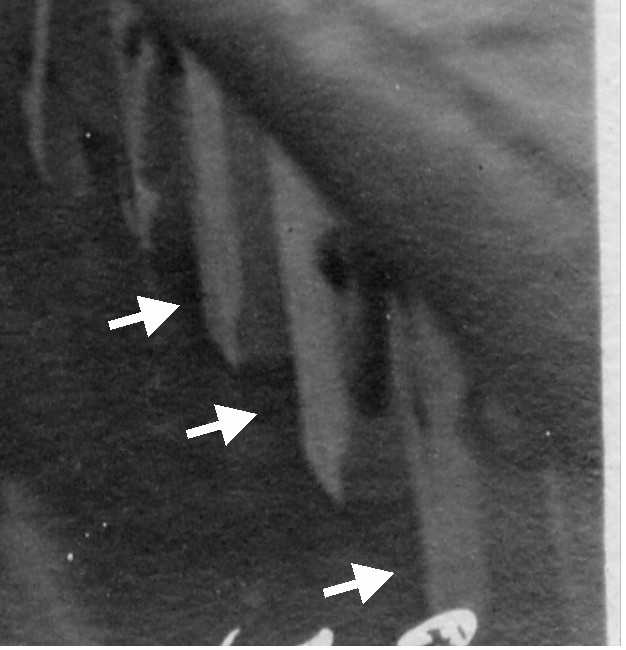
-
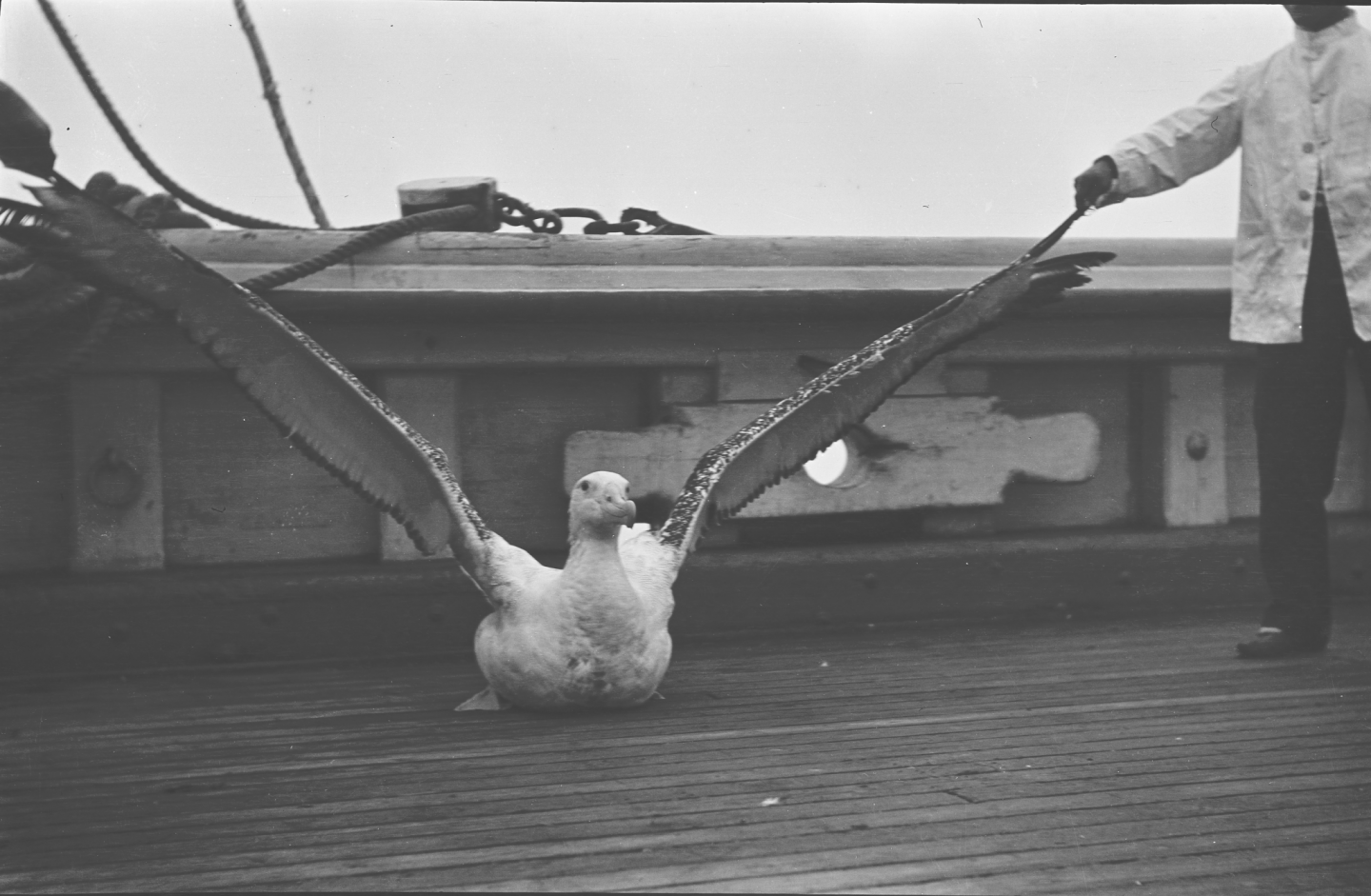
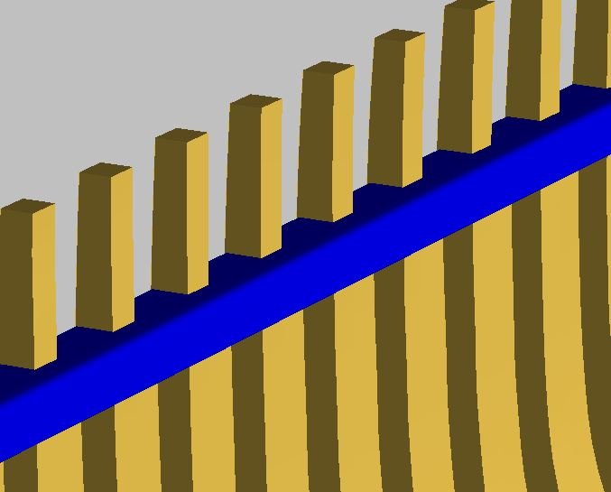
Here is another structural question pertaining to late 19th-century merchant ships. In the 1891 brigantine Galilee, there were massive waterway timbers (11 in. by 15 in.) visible in the photos provided by the Department of Terrestrial Magnetism (ignore the albatross). It is apparent that the waterways, or something else, filled in the open space between the stanchions formed by the upper frames. My question is this: Were the waterways notched for each stanchion, or were there filling pieces (or whatever they are called) added to close off the spaces between stanchions? Since the ship's bulwarks are open, there were no covering boards to prevent the entry of seawater between the frames. The following image from my digital model illustrates the question. Thanks in advance for your assistance.
-
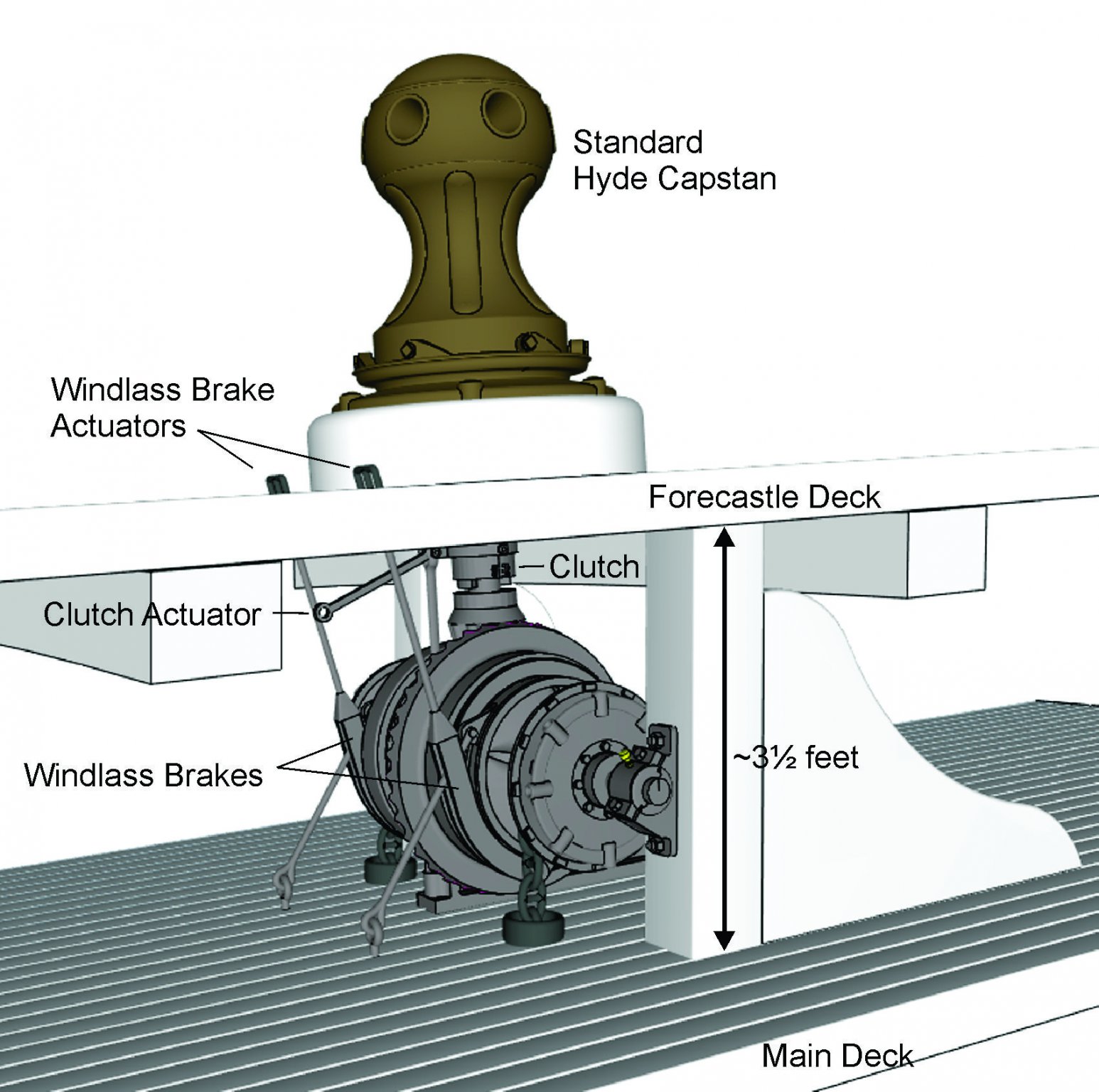
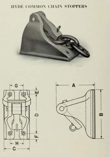
And here is my reconstruction of the capstan and windlass installation in Galilee. Basically, the screw actuators that tensioned the band brakes on the windlass drum were replaced by pry bar-actuated rods that tensioned the band brakes. I'm still not satisfied with the results because the loops which the pry bar fingers engage are much closer to the base of the capstan in my model than shown in the cyanotype photo. So, either the linkage is at a different angle than in the model or there may be a different lever configuration relating to the band brakes themselves. I suspect that windlass installations could be customized as needed to fit the ship. There is one final detail that needs to be created for the forecastle equipment, and that is locating and installing the chain stoppers. Hyde's catalog shows them looking like this:

- 21 replies
-
- 1
-

-
- capstan
- hand windlass
- (and 3 more)
-
Hello Lane. Thank you for your efforts and interest. I'm in the process as we speak of changing out the local hand-crank brake actuator to the topside lever device in my digital model. Looking forward to seeing what you have. Thanks again. Terry
- 21 replies
-
- 1
-
-
- capstan
- hand windlass
- (and 3 more)
-
Need CAD type program
CDR_Ret replied to Sambini's topic in CAD and 3D Modelling/Drafting Plans with Software
For the DELFTship fans out there, I've posted my latest project in my main plans research thread showing some of the things you can do with the program. Terry -
Wefalck, Thanks for the information. In the case of Galilee, she was actually conducting geomagnetic research using very sensitive declination, dip, and, intensity instruments, as well as several standard ship's compasses in general use at the time. The ship swings were essential for cancelling the local influences to determine the absolute elements of the earth's magnetic field. As an aside, the Carnegie Institution eventually built a completely non-magnetic research vessel (the Carnegie) and continued Galilee's work into the late 20s. Sadly, the ship was destroyed by a fire caused by, you guessed it, gasoline fumes igniting explosively. The ship's captain, a former coworker and a good friend of my grandfather, was killed in the explosion. An update to this post: I've posted my reconstruction work for Galilee's launch in my research thread here. Terry
-
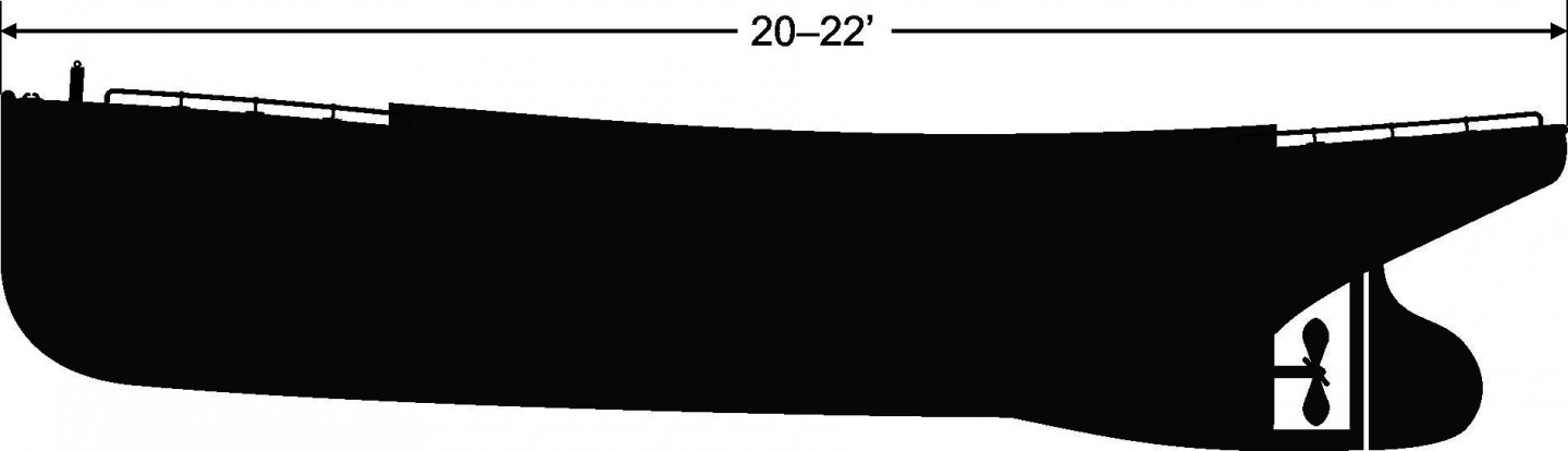
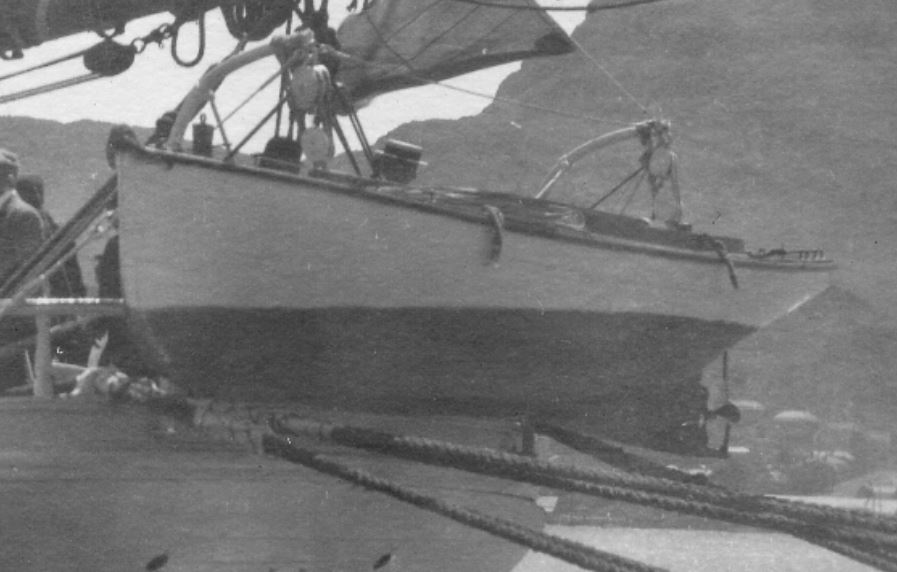
Evidently this particular "boat" topic has never been brought up in this forum. Late in the 1800s when builders were toying around with more compact and energetic sources of energy for propulsion, they developed the naphtha engine, which used volatile fuels produced by the distillation of petroleum to either heat water to steam or, eventually, to produce propulsion by internal combustion. It was the precursor to gasoline engines. Between the 1890s and around 1905, small- to medium-sized vessels called naphtha launches were very popular with the boating public, and thousands were built by companies such as the Gas Engine and Power Company for recreational and commercial use. Now to my question: The brigantine Galilee, in which my grandfather sailed, was conducting magnetic surveys of the Pacific Ocean between 1905 and 1908. Because the vessel was not entirely nonmagnetic due to the hundreds of iron fasteners in her hull and some steel and iron rigging components that couldn't be removed, she produced a small by measurable magnetic characteristic that had to be accounted for in the sensitive measurements and calculations of the earth's magnetic field. This was accomplished by measuring the earth's field elements on various courses at sea, and turning the ship in harbors at the ports she visited. The former was done using wind, sails, and rudder. But the latter was very difficult without outside assistance, and very time consuming. To deal with this problem, on her second and third cruises, she was equipped with her very own—naphtha (or more probably, gasoline) launch—carried in beefed up davits off her stern. Sadly, I don't have very many photos of the launch to finalize my reconstruction of the plans for the ship. Courtesy Department of Terrestrial Magnetism, Carnegie Institution, Washington, DC This is an approximation of what I can see: According to various sources, the boat is described as a plumb-bow fantail launch. My best approximation of its length is about 20–22 feet long. Its depth is about 4 to 5 feet. I have no idea of the beam, since there are no views of this detail. I don't even know if there is a transom or if the stern is elliptical or canoe-shaped, like many of the available plans of this type of vessel show. If anyone knows of sources that show either this particular type of launch or one similar to it, I'd appreciate direction to them. I've already checked out most of the diagrams available on the web, but if there is one that looks close to this boat, and in particular shows the plan and body views, those would be of great help. Terry
-
Need CAD type program
CDR_Ret replied to Sambini's topic in CAD and 3D Modelling/Drafting Plans with Software
With regards to DELFTship, I am using the program to determine the true deck line along the bulwark of Galilee's hull plan reconstruction. I thought it might be useful for those trying to learn the program if I did a mini-tutorial as I worked on the problem. The first post of the tutorial starts here. I'm including lots of discussion on program features that are really glossed over or ignored in the program manual. Please let me know what you think of the presentation and suggest anything that could be improved upon. Thanks! Terry -
Need CAD type program
CDR_Ret replied to Sambini's topic in CAD and 3D Modelling/Drafting Plans with Software
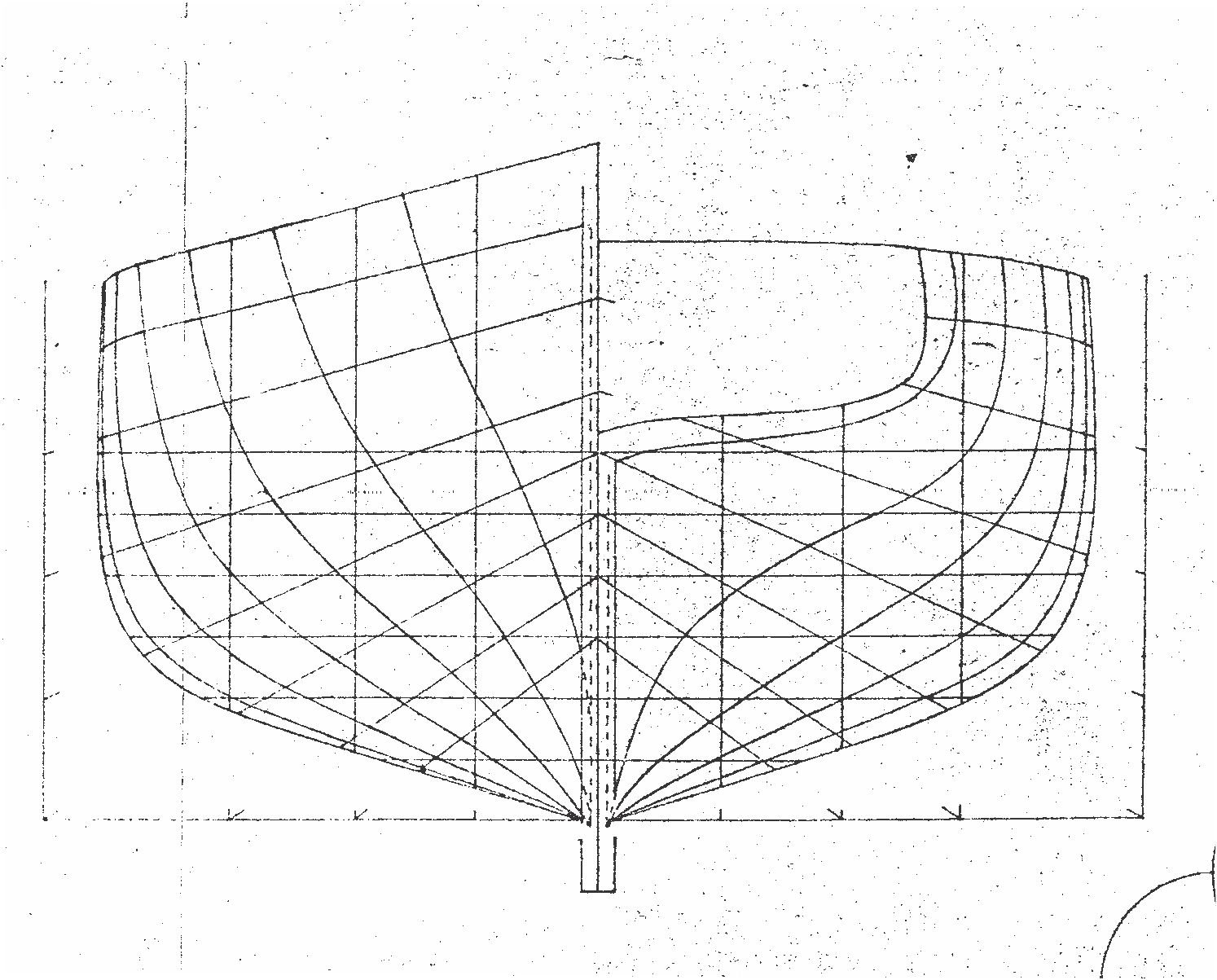
I have been devoting a lot of time to DELFTship in the past few weeks while "social distancing." This is the hull of the 1891 brigantine Galilee, in which my grandfather sailed between 1906–08. The hull lines are based on the G.C. Berger plans available from the Smithsonian HAAMS program. They need a lot of work to make them usable, which is why I used DELFTship. The interior views of that old ship are really amazing! Terry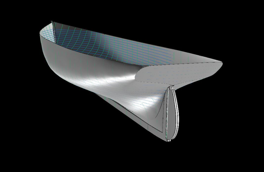
-
Galilee's Rabbet
CDR_Ret replied to CDR_Ret's topic in Building, Framing, Planking and plating a ships hull and deck
Well, I've spent some of my time during the past two weeks self-isolating from coronavirus exposure to sort through the rabbet question. After taking a look at the DELFTship model as I left it last Fall, I realized that there was very poor fidelity between the model and the original Berger lines plan. So I basically decided to work over the model lines again to attempt as much as possible to approach the original lines. After several iterations, I realized that the lines in the halfbreadth, elevation, and body plans simply were not compatible, so I did the best I could to at least approach the hull shape that produced fared station, waterline, and buttock curves. Considering that I basically had to build the aft end and transom from scratch using reference photos and the real ship had a 5-inch hog, the results were pretty gratifying. As a result of this work, I am posting several other new items pertaining to the Galilee plans elsewhere in the forums. All that to say that I needed a fairly stable set of station lines so I could determine the angle of the garboard strake to identify the rabbet lines. The results are shown below. As we discussed, the back rabbet line curves upward along the middle run of the keel and becomes nearly flat at the ends before reaching the stem and sternpost. The thickness of the strake is full thickness at 6 inches while it thins down to 3 inches, which is the hull planking thickness, at the ends of the hull. Terry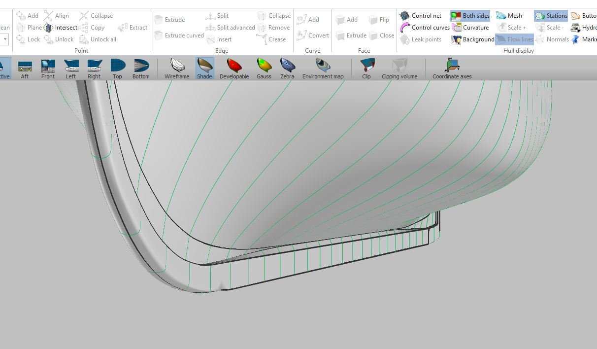
-
Homemade Shop Dust Masks
CDR_Ret replied to CDR_Ret's topic in Modeling tools and Workshop Equipment
Nice looking masks, Bob. My wife says she has enough elastic for the apocalypse, which she has been collecting for decades. -
Well, with the coronavirus panic-buying depleting all the dust masks at our local home improvement stores, I was at a standstill with some of my workshop projects. However, my wife has been following some fabric arts forums where they are discussing making masks for hospitals to supplement those needed for non-critical care situations, so they can use the N-95-esq masks for critical care/COVID-19 cases. So, she found the pattern, we selected a fabric, got the elastic bands, and I made a nose-bridge support out of a piece of copper wire. The result looks like it will work fine!

-
Intellectual property
CDR_Ret replied to woodrat's topic in CAD and 3D Modelling/Drafting Plans with Software
This document from copyright.gov may provide guidance. I'm not a lawyer, but creating a detailed lines plan for sale from general lines plans in a published reference may not be considered a derivative work exempt from getting permission. Terry -
Galilee's Rabbet
CDR_Ret replied to CDR_Ret's topic in Building, Framing, Planking and plating a ships hull and deck
Thanks, Wayne. Excellent summary of the problem. I haven't done much of this kind of research, so everything you said makes sense. Appreciate the input. Terry -
Galilee's Rabbet
CDR_Ret replied to CDR_Ret's topic in Building, Framing, Planking and plating a ships hull and deck
Thanks, Bob. I'm in complete agreement with your assessment of the DTM draftsmen. During the field assessment, the engineers may have been able to obtain some verbal description of the hull's construction to add to what could have been visually verified from inside the hull. But trying to put all that together into dimensional drawings may have included some guesses. As I noted in several posts in my Galilee thread, Berger's plans, or at least the subject, seem to predate the HAMMS project, which occurred in 1936–37. That idea may be in error. Berger's plans show her as a brigantine, but by the early-30s she was a an aging three-masted fishing schooner and had many alterations to support the fishing industry. According to her history documented in R.A. Stradford's Brigantine, Schooner, Houseboat: Journeys of the Galilee, the vessel was purchased by an ex-pat British captain named John Quinn, who with his wife used it as a houseboat, beached in the Sausalito mudflats from 1934 until the late 1950s. The Berger plans include a note thanking J. Quinn as the last owner of the Galilee (as well as Ray Bowes) for assistance in the production of the plans. However, the plans show the ship as a brigantine, so he must have used the ship-as-houseboat mainly to confirm her overall dimensions and arrangement. His plans, which are now part of the HAMMS archive (and are copies of copies of copies ...) look very similar to C.G. Davis's Rudder magazine drawings from 1899, including the erroneous transom shape. With the ship moored and/or in the mud, I'm not sure how Berger could have validated much of the keel configuration. So, I think I will do the best I can to map out the rabbet assuming a more-or-less rectangular garboard strake that tapers from 6" to 3" thick in the vicinity of the bow and stern. Terry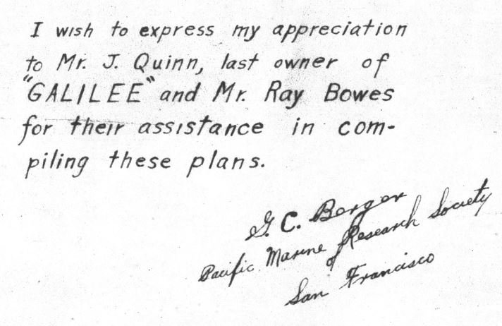
-
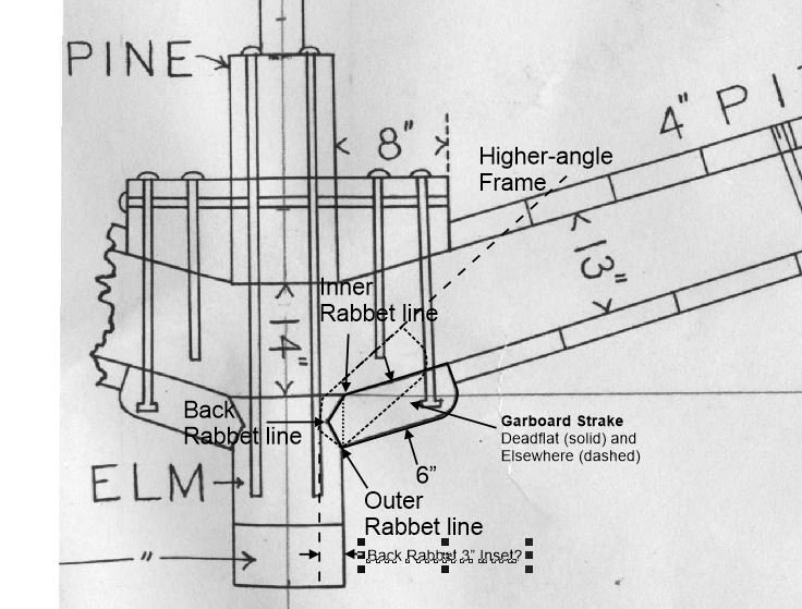
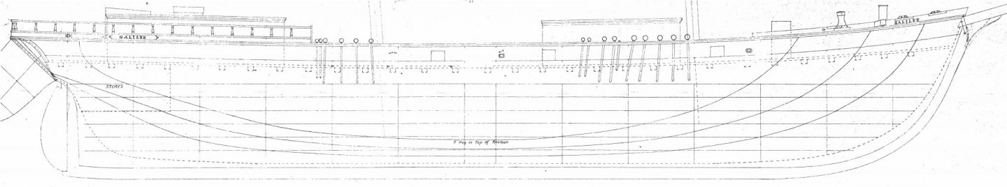
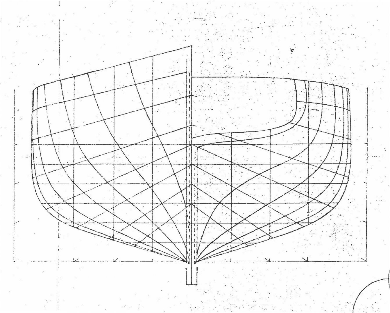
Hi all. After a hiatus of nearly six months, I have been able to get back to working out some of the details of Matthew Turner’s brigantine Galilee. While attempting to clean up the rabbet along the keel, stem, and sternpost in DELFTship, I ran into some issues that call into question the original G.C. Berger plans I obtained from the Smithsonian. This isn't the first time this has happened. Check out my research and design log on this ship. So the following is a series of technical questions about rabbet lines and garboard strakes. Let’s start with a description of the rabbet at the dead flat. The following diagram was created by the scientist-engineers at the Department of Terrestrial Magnetism, Carnegie Institution, Washington, D.C. (DTM) sometime around 1904–5, when they were planning the conversion of Galilee from a merchant ship in the Tahiti trade to a magnetic research vessel. They needed to know where all the ferrous hardware was located in the hull to figure out the magnetic constants for the ship. For that reason, they took fairly good measurements of the hull, though their drafting skills could have used some work … Note that the inner rabbet line lies at the point where the frame intersects the face of the keel. This is a key factor in the following discussion. The back rabbet and rabbet as shown in the first diagram do not conform to the shape shown in many references. In most diagrams, the back rabbet line lies on the face of the frame, which intersects the rabbet at a right angle. Instead, in this diagram, the top surface of the garboard is beveled at the inner rabbet line, giving the inner edge of the garboard a point. The top surface of the garboard strake ends at the inner rabbet line, the “point” is at the back rabbet line, and the bottom corner is at the outer rabbet line. I’m not sure how the non-naval DTM engineers knew to draw the rabbet profile like this unless they obtained that detail from Matthew Turner himself. According to the DTM drawing, the garboard is about 6” thick. However, the vertical dimension of the rabbet as seen in the side profile view from the outer to inner rabbet lines should vary as the angle of the frame increases or decreases along the keel. The flatter the frame, the closer the distance between the inner and outer rabbet lines should approach the thickness of the garboard. The steeper the frame (e.g., toward the bow or stern), the wider the outer to inner rabbet line distance should be. This diagram illustrates the geometry: © Department of Terrestrial Magnetism, Carnegie Institution, Washington DC Curiously, the Berger plans don’t indicate a significant divergence of the outer (solid) and inner (dashed) rabbet lines except at the extreme ends of the keel: © Smithsonian Institution Now, let’s consider the thickness of the garboard in the first diagram. As mentioned earlier, the garboard strake is 6 inches thick. The lower hull planking is 3 inches thick. This makes the garboard twice the thickness of the adjacent planking. According to Rules for the Construction and Classification of Wood Ships (ABS, 1921), garboards must have the full scantlings for at least three fifths of the length amidship. Granted these rules were promulgated thirty years after Galilee was built, they seem to agree more-or-less with other contemporary references I have found. So, if the garboard strake stays the same thickness along most of its length, the inner rabbet line is going to curve upward as the frame angle increases. Only if the garboard thins gradually as it approaches the stem and stern areas, will the inner rabbet line stay more or less parallel to the outer rabbet line. Another factor is that several views of the Berger drawings show dashed lines inset at about 3 inches from the sides of the keel as shown below. These seem to indicate the depth of the back rabbet line. If the garboard strake’s thickness remains the same for most of the length of the ship as noted above, then the back rabbet line’s depth from the sides of the keel would also vary as the frame angle changes. (Another possibility is that the dashed lines show only the back rabbet line inset at the stem and stern, though they are visible in the plan view of the keel as well.) © Smithsonian Institution So, either Berger erred in drawing the inner rabbet line as a straight line for as long as he did along the keel, or the garboard changed in thickness as its angle to the keel changed to maintain that straight line. I'm in a quandary as to what the right answer is. Does anyone have thoughts or critiques of this analysis? A good resource for this question is this video of cutting a rabbet along the keel of a modern 150-foot wooden ship using traditional techniques. Also, check out the other links in the left margin of the video page! Thanks for the assist. Terry
-
Exploring FreeCAD for ship modeling
CDR_Ret replied to TonyM's topic in CAD and 3D Modelling/Drafting Plans with Software
This page may be more to the point. Looks like someone thought having a ship module (workbench?) would be a good idea, then abandoned the project. -
Exploring FreeCAD for ship modeling
CDR_Ret replied to TonyM's topic in CAD and 3D Modelling/Drafting Plans with Software
I haven't checked this out yet, but there is an effort to incorporate a naval architecture feature into the FreeCAD software. The website owners are pretty up front with the fact that their work is buggy. Terry -
Hi Chief. Don't suppose you have any photos of this situation? Changing the load line of a ship isn't a trivial thing. Either the ship had reserve cargo capacity built in or someone is playing with the stability tables. It would seem that seaworthiness certifications and insurance companies would have something to say about such an act. From my limited familiarity with marine physics, I would think that the main adverse effects to raising the load line would be reducing reserve buoyancy and some effect on the righting moment (the actual effect on stability might either reduce it or increase it, depending on a number of factors). As for the weld issues, I'm having a hard time visualizing the problem. Are there gaps (broken welds) at regular intervals along the keel, that would indicate some relationship to deep frame locations? Does this condition basically flood the keel structure with seawater? Overall, welding plates between the buckles seems to be a band-aid approach to the problem. There is obviously some serious structural issues at work. Terry
-
Just bought a used copy of Underhill's book today on Amazon for $32. I skimmed the openlibrary.org copy and it has amazingly detailed diagrams of the rigging and masting details not available in the photos I obtained from DTM/CIW of the Galilee. Since this book emphasizes 19th and 20th century sailing merchants, it will likely be a good source for rigging the model. Sadly, the one diagram that I needed to reference wasn't scanned in the digital copy from the Boston Library. Terry
- 6 replies
-
- 1
-
-
- merchant
- brigantine
- (and 8 more)
-
Reserved a digital copy at openlibrary.org. That looks like a good place to obtain access to out-of-print books. Operating under a grant from California, so the site seems legit.
- 6 replies
-
- 1
-
-
- merchant
- brigantine
- (and 8 more)
-
Thanks, Henry. I'll look into that reference. Terry
- 6 replies
-
- 1
-
-
- merchant
- brigantine
- (and 8 more)
-
Hi all. Anyone know of an authoritative reference showing late 19th-century merchant pinrail diagrams? It is my understanding that belaying pin arrangements were fairly standardized by ship-type throughout most of the world, or at least within a nation's fleet, so that crew could be hired in nearly any port and would be able to serve with little additional training. I am looking specifically for the pinrail layout typical of a late-19th century, West-Coast, brigantine merchant of medium size. Any assistance will be appreciated. Terry Egolf Colorado Springs, CO, USA
- 6 replies
-
- 1
-
-
- merchant
- brigantine
- (and 8 more)