CDR_Ret
-
Posts
660 -
Joined
-
Last visited
Content Type
Profiles
Forums
Gallery
Events
Everything posted by CDR_Ret
-
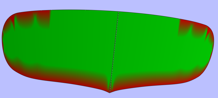
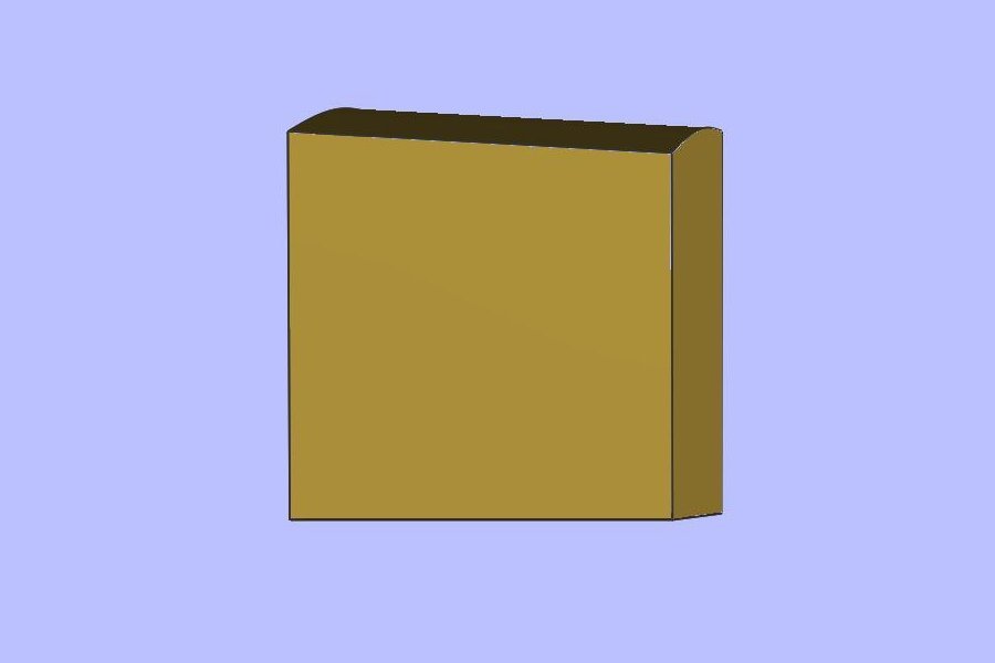
 Mustafa, Thinking that you might not be able to run DELFTship, I created the nine stations you would need to hand draft the plywood planks in my 2D program. This is what I came up with: A couple of issues are evident. The main problem is that the body plan is not consistent with the profile and plan views. So you will be able to use that view only for general reference. I think you can get all the important details from the other views. Also, the image is slightly tilted (less than half a degree), but that can be enough to throw off some dimensions. I corrected the tilt in this image. Even with a lower-resolution background image, you should be able to adjust the the chines to create fair edges for your plywood planks. If you view the surfaces using the Developable tool——you should be able to adjust the crease edges to create a completely fair surface. What you are looking for is a solid green color indicating the surface curves in only one direction or is perfectly flat. This means you can cut the plank out of a flat piece of plywood stock. Usually the program will show red shading near the edges, especially if the edges themselves curve in more than one direction. This is how my brigantine's cylindrical transom looks because of this effect: As far as sizing the background images and other considerations for starting a DELFTship project, see my tutorial available at this page here in this forum. Again, contact me if you need some assistance getting started. Cheers! Terry
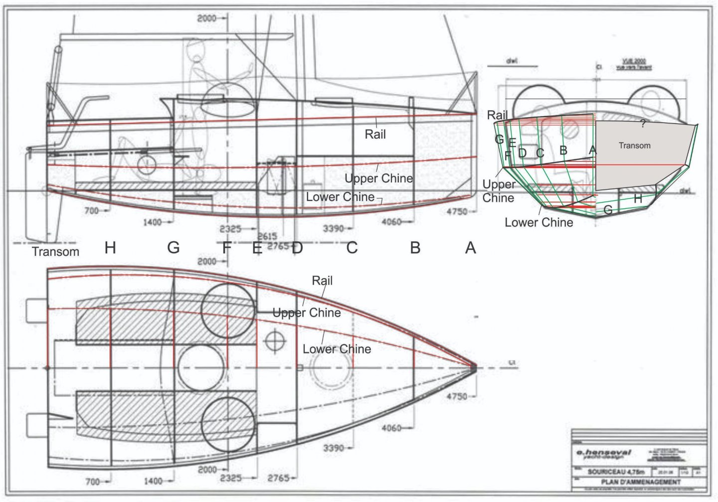

-
Mustafa, I think DELFTship is a Windows-only platform, sadly. But like Roger said, you can create stations along the length of the hull in both profile and top views. Then pick off heights and breadths of the "chine" lines at each station and plot them in the body plan view. When you connect the dots with with straight lines at each station, you have your third view. The harder part will be generating the true shapes of the plywood planks. I think this can be done by drawing diagonals in the body plan view for each plank, then picking off the distances from the associated diagonal of the top and bottom edges (chines) at each station. This sounds more complicated than it actually is. [Edit: If there is a twist to the plank, I'm not sure this will actually work.] Terry
-
Hello Mustafa, I think it may be doable. The interrupted lines in the plan and profile views represent edges of developable sheets of plywood. The body plan view can provide the true widths of the sheets at the dead flat point. So your software should be able to create the necessary pieces in 3D. Does your software "unwrap" surfaces to create the plywood templates? If not, I recommend DELFTship Free. This program also allows you to create truly developable parts using visual cues such as solid colors. Let me know if I can be of further help. Terry
-
I need longer fingernails...
-
I've noticed that browsing presence is often absent, too, in the mobile version of the site (Android phone using Chrome). Terry
-
Feature Suggestion
CDR_Ret replied to CDR_Ret's topic in Using the MSW forum - **NO MODELING CONTENT IN THIS SUB-FORUM**
B.E.'s solution works and that's a plus. However, the fact that the image folder's name is an active link was totally unknown to me and, obviously, to other members. I still think it would be more useful and intuitive if the scroll arrows were active as soon as you enlarge a gallery image. Why not move this feature up one layer so the casual viewer can scroll through all the images that are in the Gallery ribbon? Alternatively, include some kind of label or tool tip that alerts (new) users that you can scroll a particular album. Or do both. Reserve the large, really high-resolution images for the folder view. Terry -
Heh. Now if I could actually get to building the model, that would be an accomplishment! Looking forward to seeing how this comes together, Mike. Terry
-
It would be a convenience to have right- and left-scroll buttons added to the individual photos in the Gallery at the top of the MSW forum page. This way, one doesn't have to exit the photo currently being viewed to look at the next one in the series. Terry
-
Hi, anaxamander49. I have attempted creating ship plans in Sketchup, Blender, Fusion 360, and DELFTship Free. All of these are open source, have free licenses for hobbyists, or are offered as a free version of the professional software. Sketchup creates surfaces in polygons and there is no utility for creating useful hull plans that provides the information a ship model builder needs (e.g., stations, waterlines, and buttock lines). Also, if you attempt to scale down a full-sized digital model to model size, you risk losing precision in fine details due to the way Sketchup works (points, lines, and polygons simply disappear!). Blender and Fusion 360 have (very) steep learning curves and, again, they don't really lend themselves to creating 2D building plans useful to ship modelers without a lot of fiddling around. While Blender is an amazing program, its developers are continually revising the features and interface, so a casual user never gets up to speed in the program. DELFTship Free, in my opinion, is your best bet for creating useful working ship model plans. The program's 2D plan output shows the hull and expected details in standard profile, body, and plan/halfbreadth views. These views can also be customized to show specific objects and omit others, if desired. The program can export 2D DXF images in polyline format that can be imported into 2D vector graphics software for editing and formatting. In addition, the model surface is a true subsurface object that can be precisely shaped with a customizable control net to match existing 2D plans, if required. Like you, I used the program to reconcile incompatibilities among the three views of an existing set of hull drawings that I have come to believe was an unknown mixture of conjecture and actual measurements. The result was a fair hull that seems to reflect contemporary photos of the ship. If you haven't already, I recommend reading through the many topics within this CAD and 3D Modelling/Drafting Plans with Software forum pertaining to the various 3D software others have attempted to use when creating ship plans, and then draw your own conclusions. If you are having difficulties getting started with DELFTship (the manual isn't very good on work flow or process, just feature capabilities), please contact me or the other members who have used the program. Having a guide can help you past many of the frustrating aspects of this program. Best regards. Terry
-
Ladder steps
CDR_Ret replied to allanyed's topic in Discussion for a Ship's Deck Furniture, Guns, boats and other Fittings
My two cents, which basically corroborates what has been stated previously ... The following information is abstracted from pages 316 and 317 of The American-built Packets and Freighters of the 1850s: An Illustrated Study of Their Characteristics and Construction by William L. Crothers. In the mid-19th century, the spacing of ladder rungs and stair treads was dictated by the natural step of the average 5-foot, 8-inch man (according to Crothers—a value he never provided!). Vertical ladders for accessing deckhouse roofs had equally-spaced rungs. The distance between the upper rung and the roof surface was the same as between the lower rungs, to avoid creating a surprise and misstep when accessing the roof. The lowest rung was at a variable distance above the deck, but could be a larger step than the space between the other rungs. Stringers were at least 4 inches deep to provide toe room at each rung. If the upper end of a ladder ended at a coaming, the upper rung (or tread) was at the same height as the deck outside the coaming, again to avoid tripping or other surprises due to height differences. Inclined ladders (stairs) had treads that were closer together than vertical ladders. However, all treads were equally spaced—from each other, from the lower deck, and from the upper threshold. This is so the user experienced the same drop and rise whether descending or ascending. The number of treads was determined by the height between decks and the inclination of the stair. As the stair angle from the horizontal decreased (became less steep), the vertical distance between treads decreased, and the width of the treads increased. Again, the reference for these dimensions is the length of an average person’s step or pace, but no absolute value was given. Stairs and ladders were made for the specific location where they served and were not interchangeable. Often the lower ends of the stringers of inclined ladders/stairs were cut plumb with the deck (“dubbed off”) below the lowest tread to eliminate a tripping hazard. While the era Crothers discusses is several centuries after the OP’s interest, I imagine these principles were more or less followed from the earliest times simply due to their practicality. Terry -
Thanks David. I think everything has been said that can be said. I appreciate everyone's contribution from multiple points of view and I learned a lot, personally. Terry
-
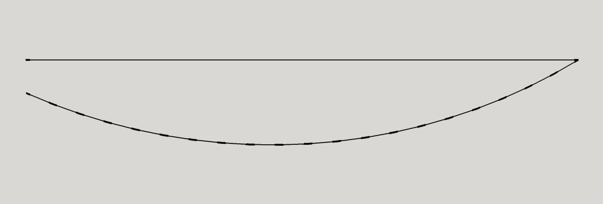
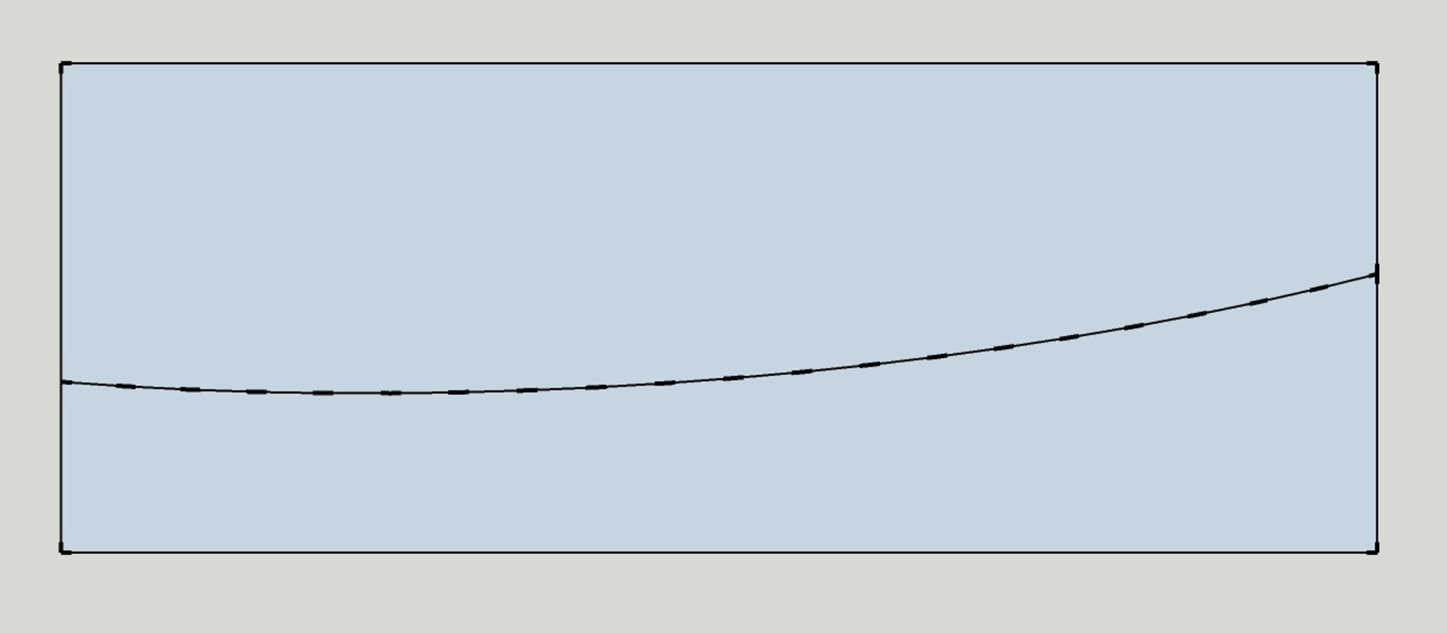
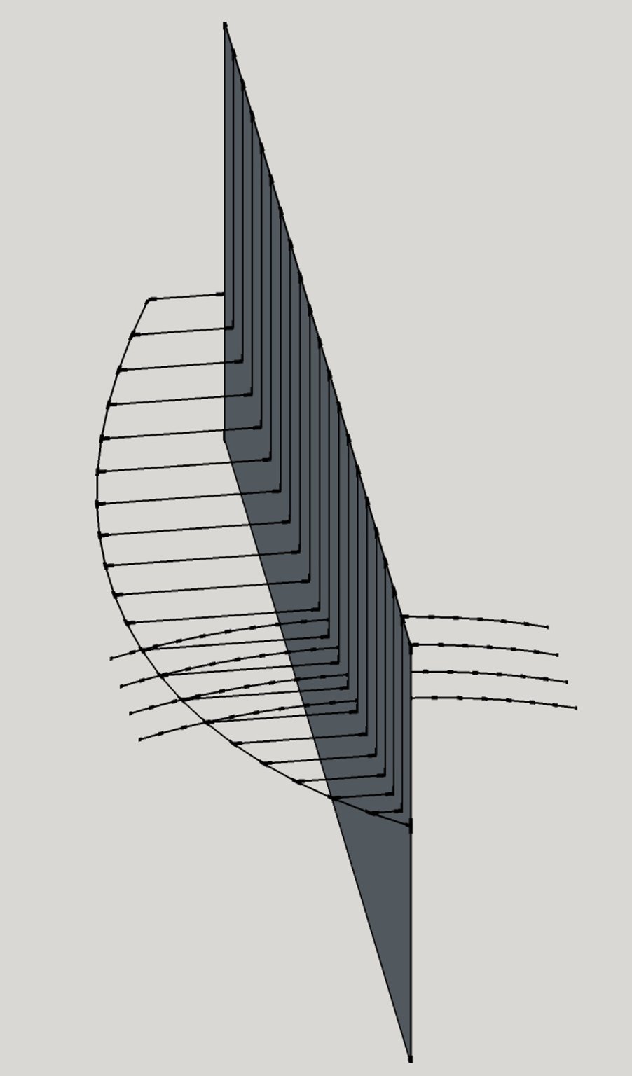
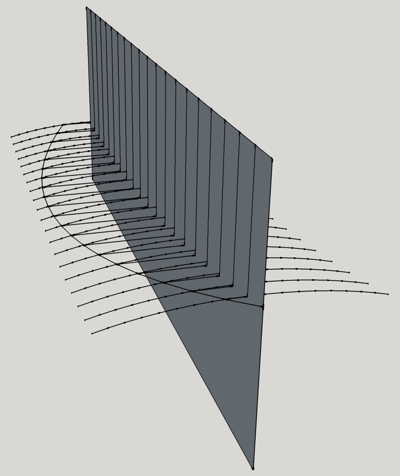
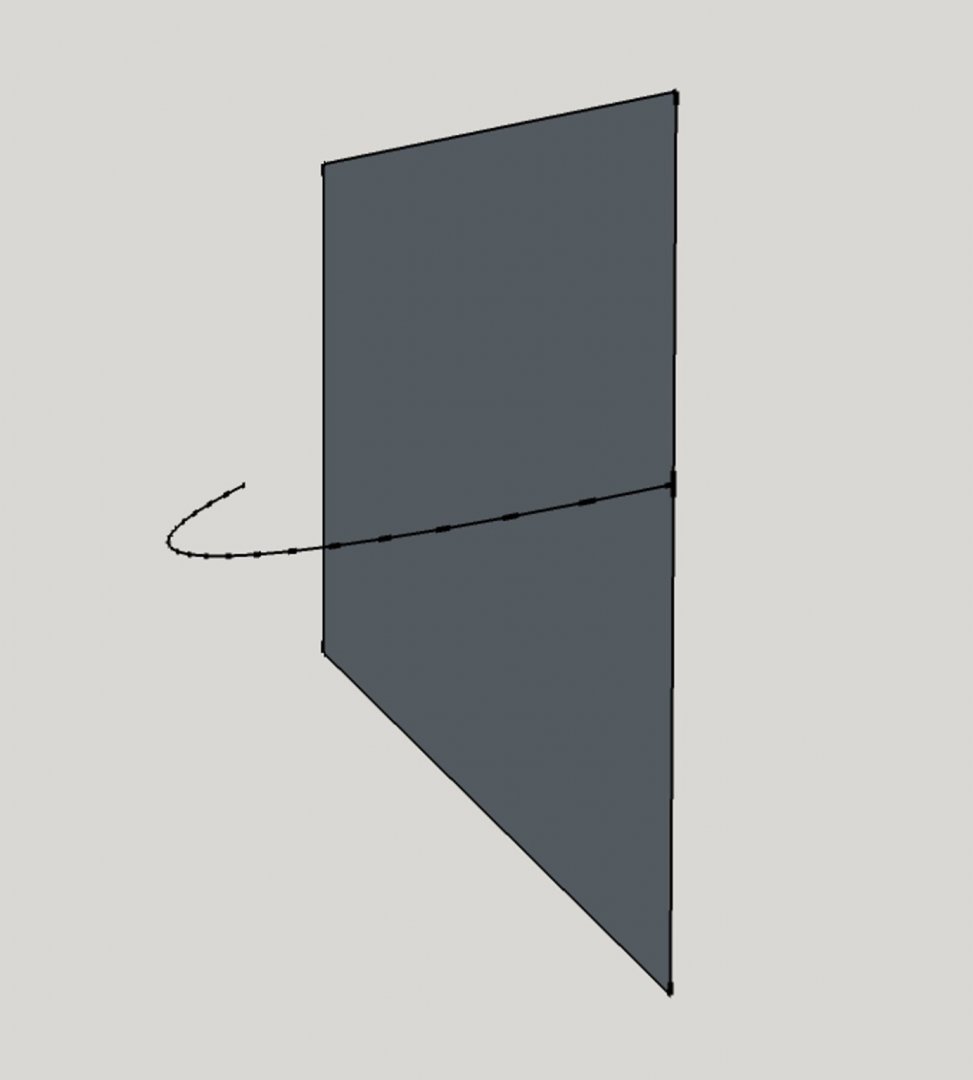
"Once again into the breach" (Henry V-Shakespeare) Because of the persistent view that a constant-camber deck couldn't produce a fair deck, but one with unfair areas in its surface, and because my last attempt to demonstrate that this was not the case was apparently derived from a non-standard approach to ship design and construction, I decided to experiment and see what the outboard-sheer-line-in approach would produce. I had no preconceived notions on this approach, but it seemed that if the outboard sheer line was fair, then it makes geometrical sense that using constant cambers in attached deck beams would also be fair, since corresponding points on the adjacent beams would fall into a curve parallel to the outboard sheer. Many mentions have been made how constant-cambered decks weren't the case in 16th, 17th, and early-to-mid 18th century ships, and I can understand how that is likely due to the relatively low length-to-beam ratios and quite pronounced sheer lines in those eras. But ships became stretched out in the latter 1700s and through the 19th century, so there was less imperative to hand-tool the deck camber, I would think. So, here goes. Using Sketchup again, I created a generic, non-circular curve in three-space and attached it to a vertical plane that corresponds to the centerline of a fictitious hull. The curve represents the outboard deck sheer of the vessel. Outboard sheer line in perspective. Plan view of the outboard sheer line. Profile view of the outboard sheer line with the centerline plane behind (looking to port). As before, I created a deck camber edge from a segment of a large circle, then placed its center point on the centerline plane. I also added horizontal and vertical guidelines to ensure each camber template was correctly placed longitudinally and on center. These identify deck beam "stations." Cambered deck beam template and positioning guides. Next, I dragged the camber template down until its edge intersected the outboard deck edge. This was repeated using duplicate copies of camber templates at each beam station line. Duplicating camber templates and positioning them at the outboard deck sheer line. Completed deck skeleton. As in the previous example in Post #32 of this topic, I "connected the dots" to create the faces forming the cambered surface. (I deleted the curves on the far side of the plane so I didn't have to create 2 million facets, only 1 million...) Cambered surface created from the camber templates. You may see where this is leading. Again, to create the deck surface as confined by the outboard sheer line, I created a "cookie cutter" from the outboard sheer line to intersect with the cambered surface. Sketchup allows you to create cutouts of 3D objects using other objects that intersect the one of interest. The cookie cutter's surface is parallel to the z-or vertical-axis of the model. Outboard sheer line turned into a cookie cutter. After creating the intersection with the cambered surface, I deleted everything but the surface of interest. Intersection that represents the outboard sheer line in the cambered surface. Deleting the surface outside the outboard sheer line, duplicating the half-surface, mirroring it, and rejoining the two half-surfaces yields a fair, cambered deck. All cambers are the same. Completed cambered deck surface. Finally, taking a look at the orthogonal profile view of the deck, we can see that, while the centerline sheer is smooth, there is a distinct flattening there in the middle, which probably would not be considered "fair" overall. The longitudinal lines in the deck that could represent deck plank edges are no longer parallel to the centerline sheer. This doesn't indicate a problem in form or function, however. Profile view of a constant-camber deck created by referencing the outboard deck sheer line. So, while this method of constructing a deck might introduce some unfairness in a deck, it doesn't seem to be a significant problem. Recall that the camber round up was exaggerated in this example. With a camber of only 6 or 8 inches, viewing the flattening evident in the above diagram over a length of several hundred feet would be indiscernible, I think. Snide comments about resorting to digital programs to support one's point aside, I don't see any other way to easily and economically illustrate the concepts we are discussing without otherwise resorting to actual plans of actual ships that were built in a particular way. Then what does that prove, except that it worked in that instance? I can't speak about cambers in the forward areas of a ship departing from a fair sheer because I haven't researched those. If anything, those exceptions probably prove the rule. If someone could present an example of such a case, I would appreciate it so I can visualize that situation. I can't conceive of shipwrights having to create numerous deck beams, all with different cambers in order to provide a fair deck in "ye olde days," but perhaps that was the case. It certainly doesn't make geometrical sense to me. Terry


-
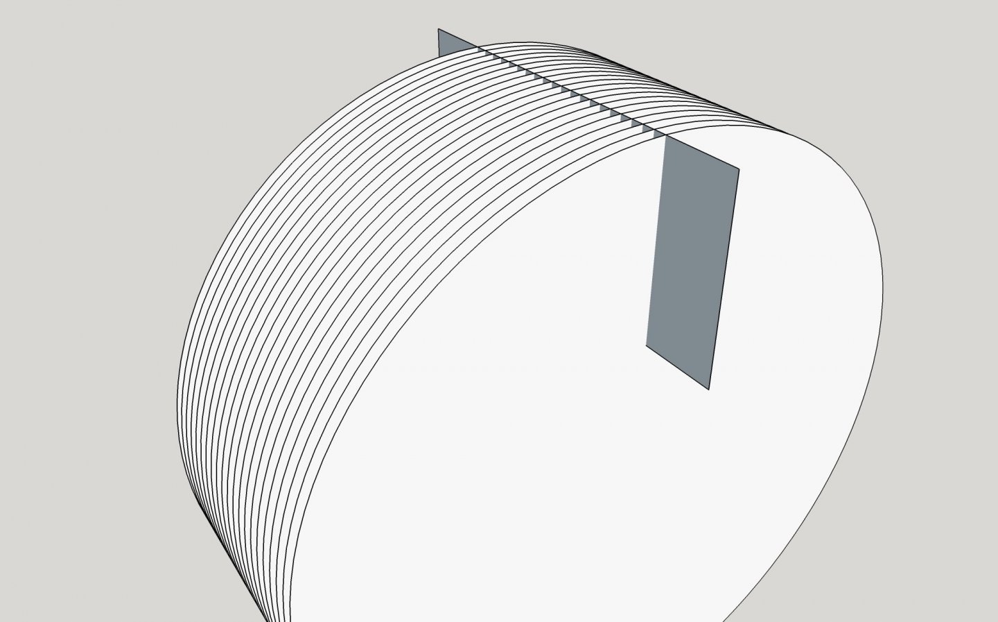
Charles, My reference to a "cookie cutter" is literally what I meant. Think of a quasi-cylindrical tube with a cross-section in the shape of the plan view of a hull, which is the white, boat shape in the image. The cutter intersected the camber surface along the z- or vertical-axis, so the result is a true, three-dimensional shape in all dimensions. Crothers claimed that mid-1800s ship decks were constant camber. My post was intended to simply refute the claim that a constant cambered surface could not produce a fair deck surface. As with many areas of creative human endeavor, making absolute claims about how something can be done simply doesn't hold true because someone always comes up with an effective alternative. Terry
-
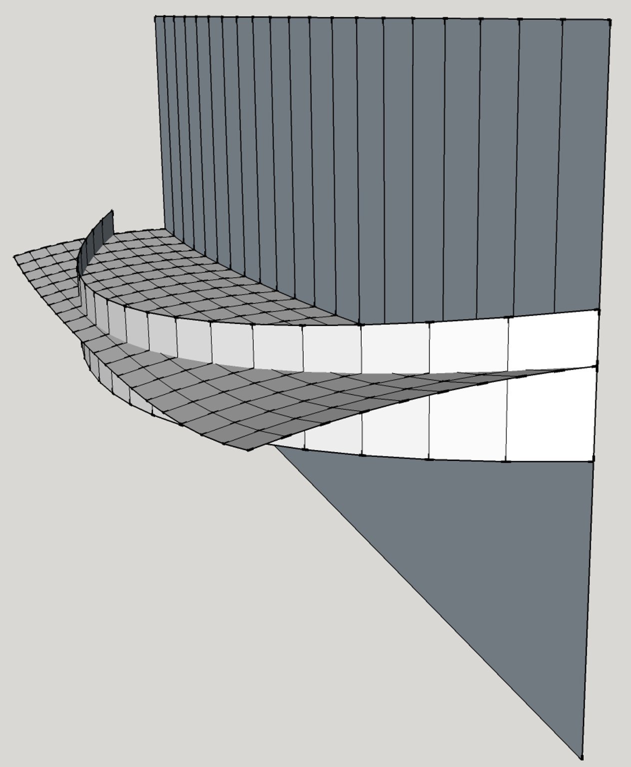
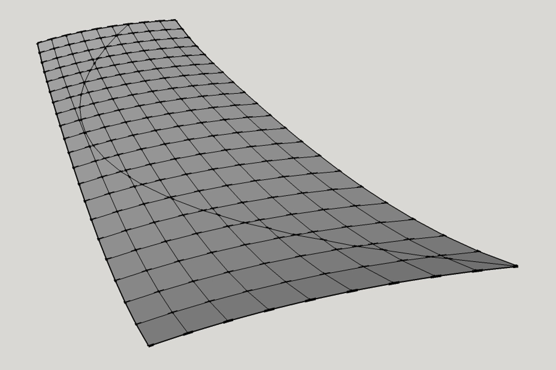
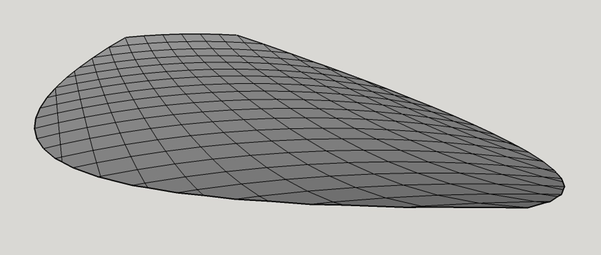
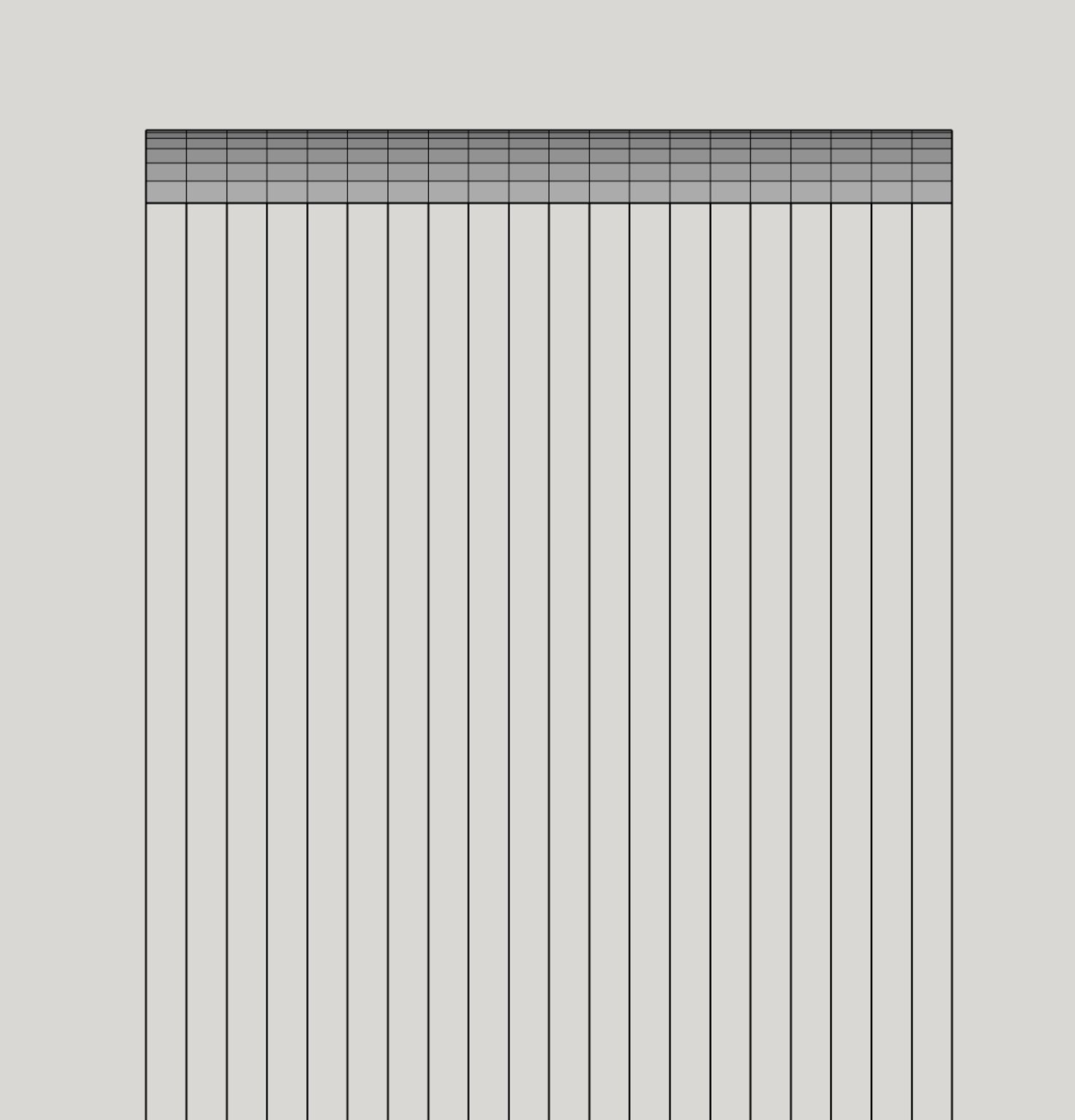
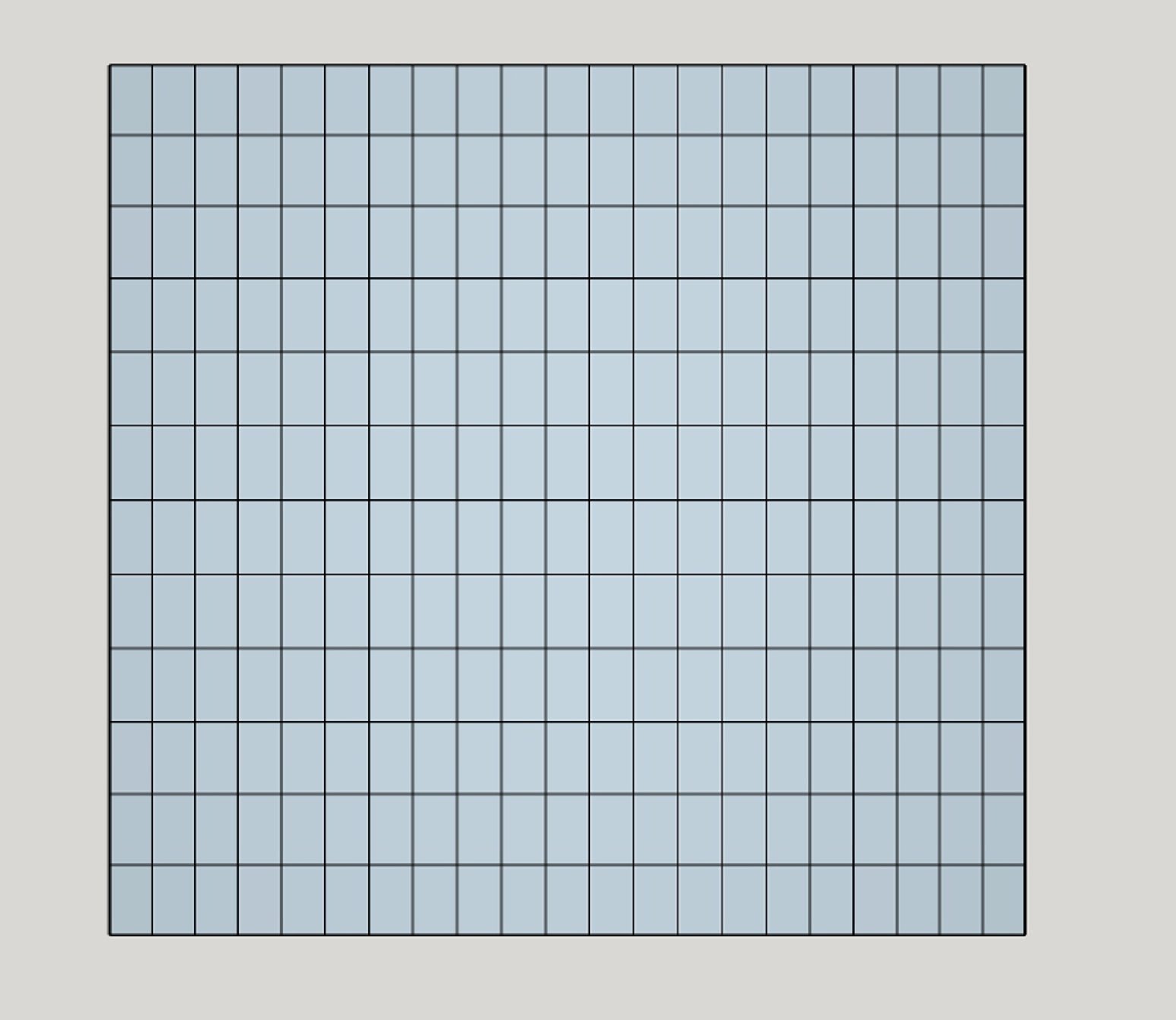
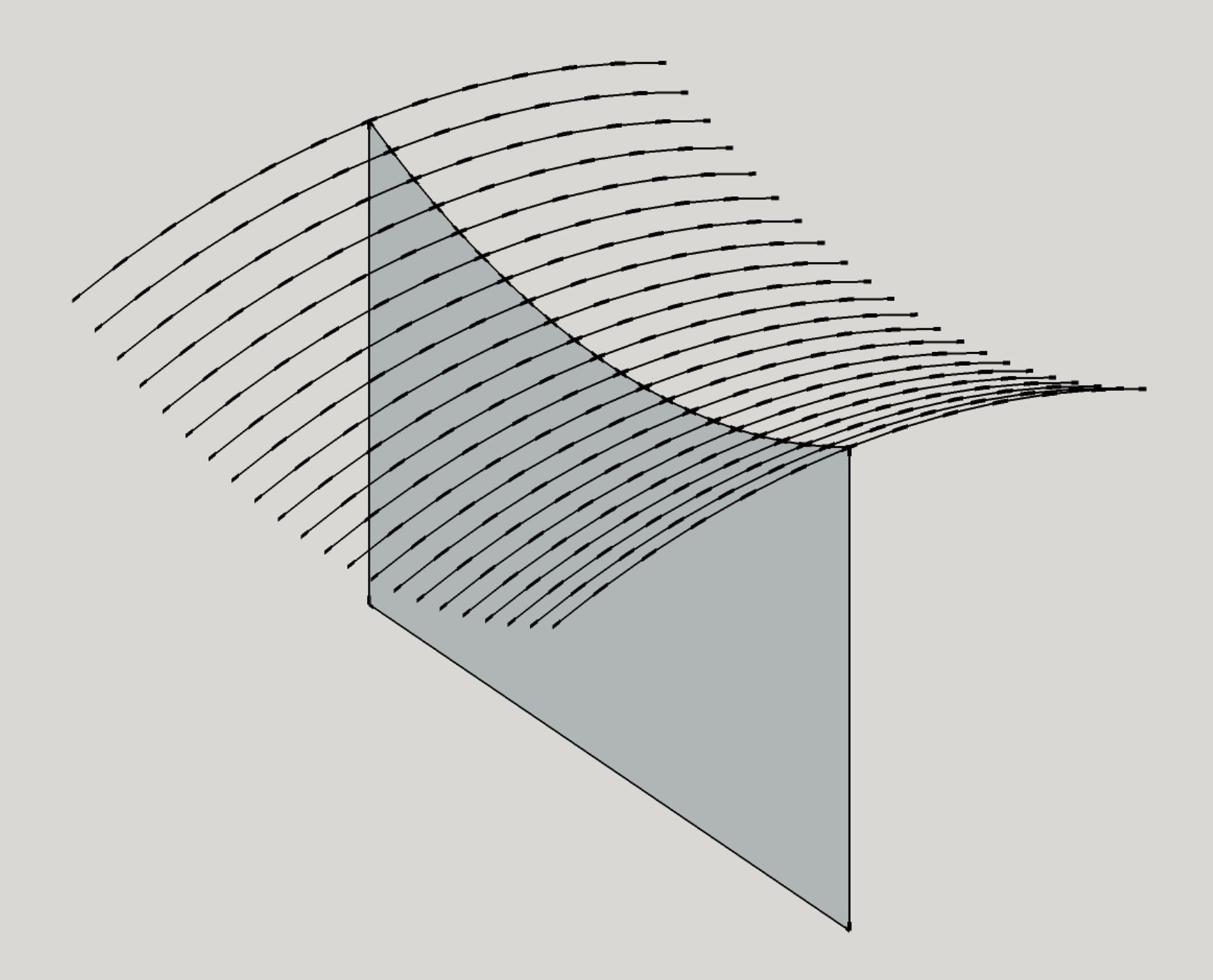
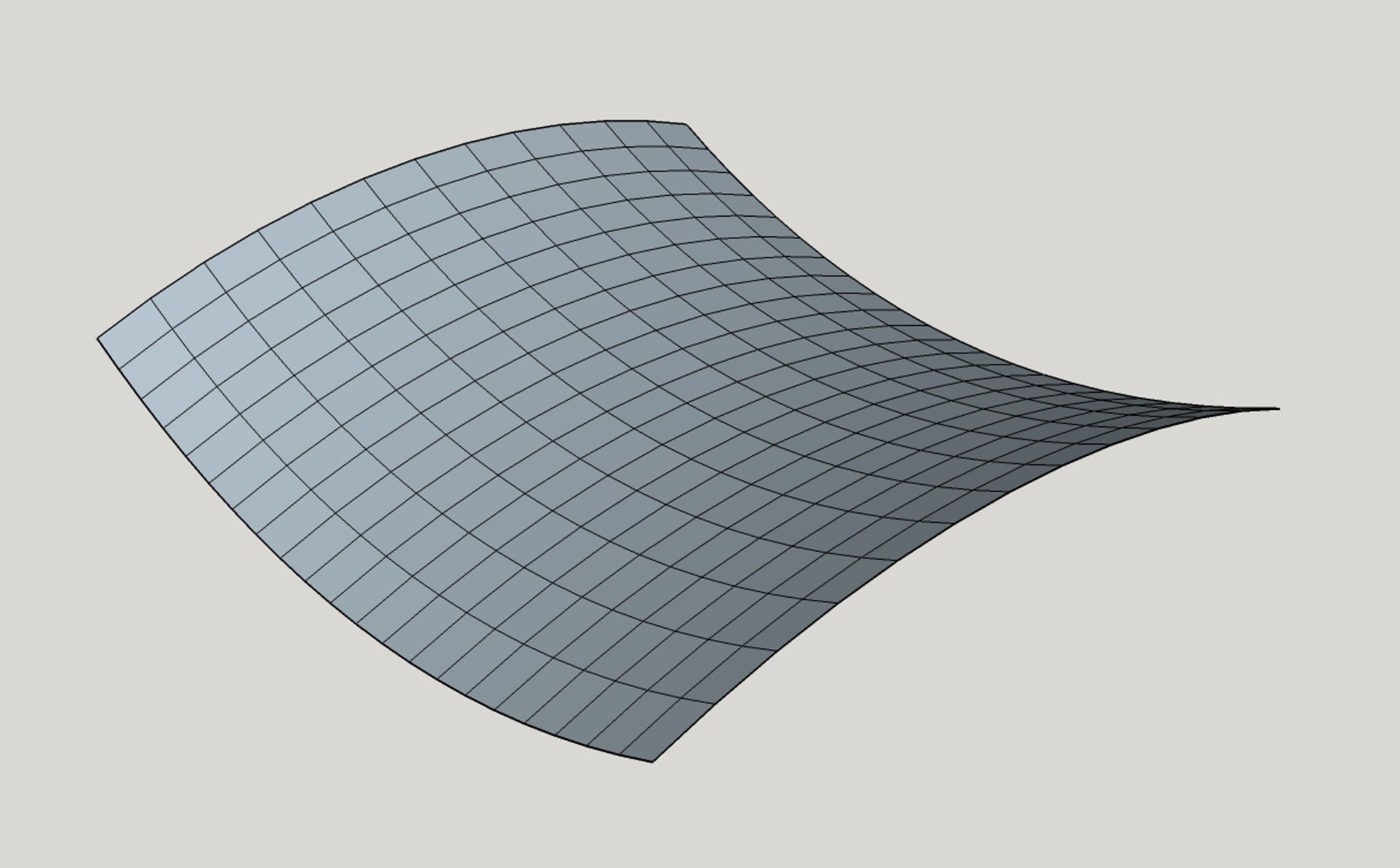
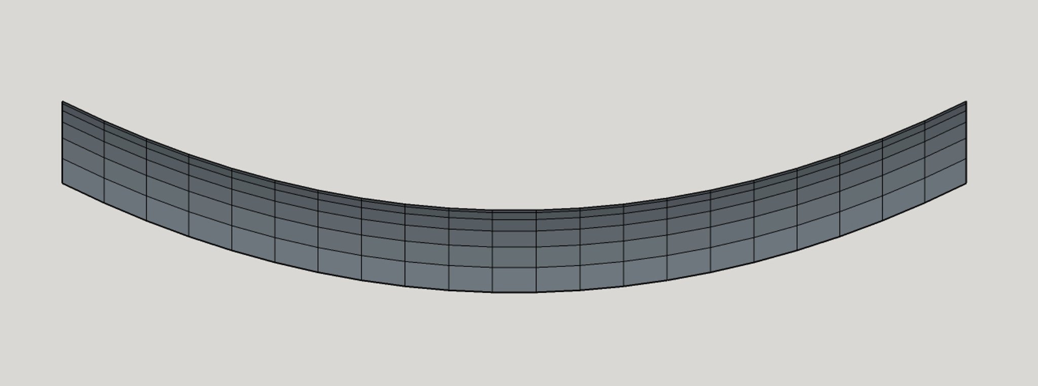
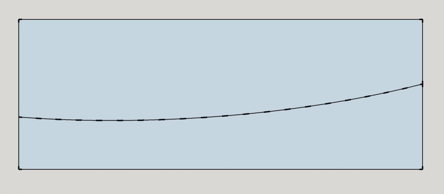
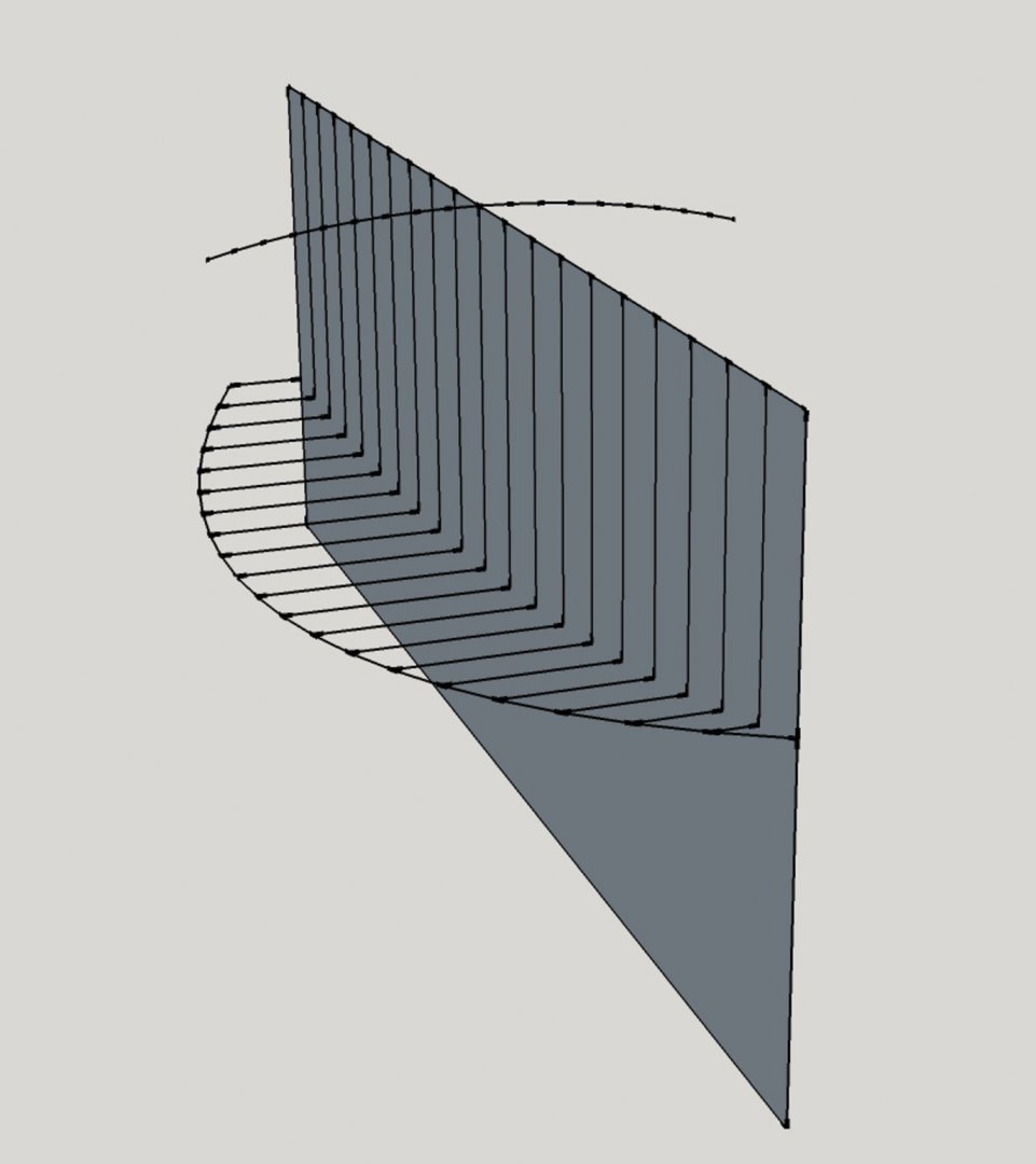
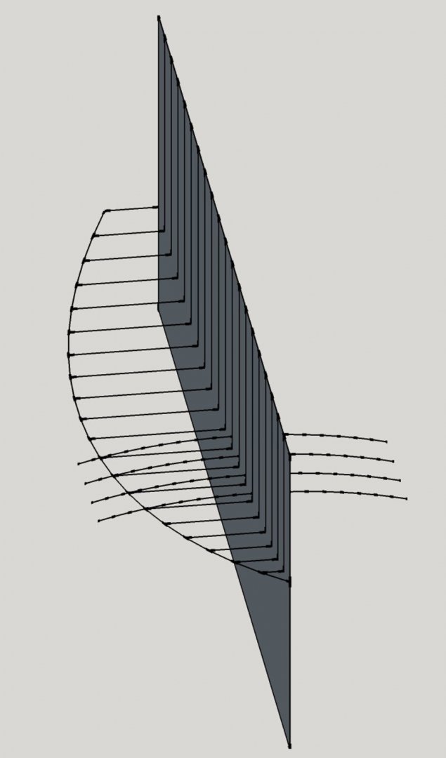
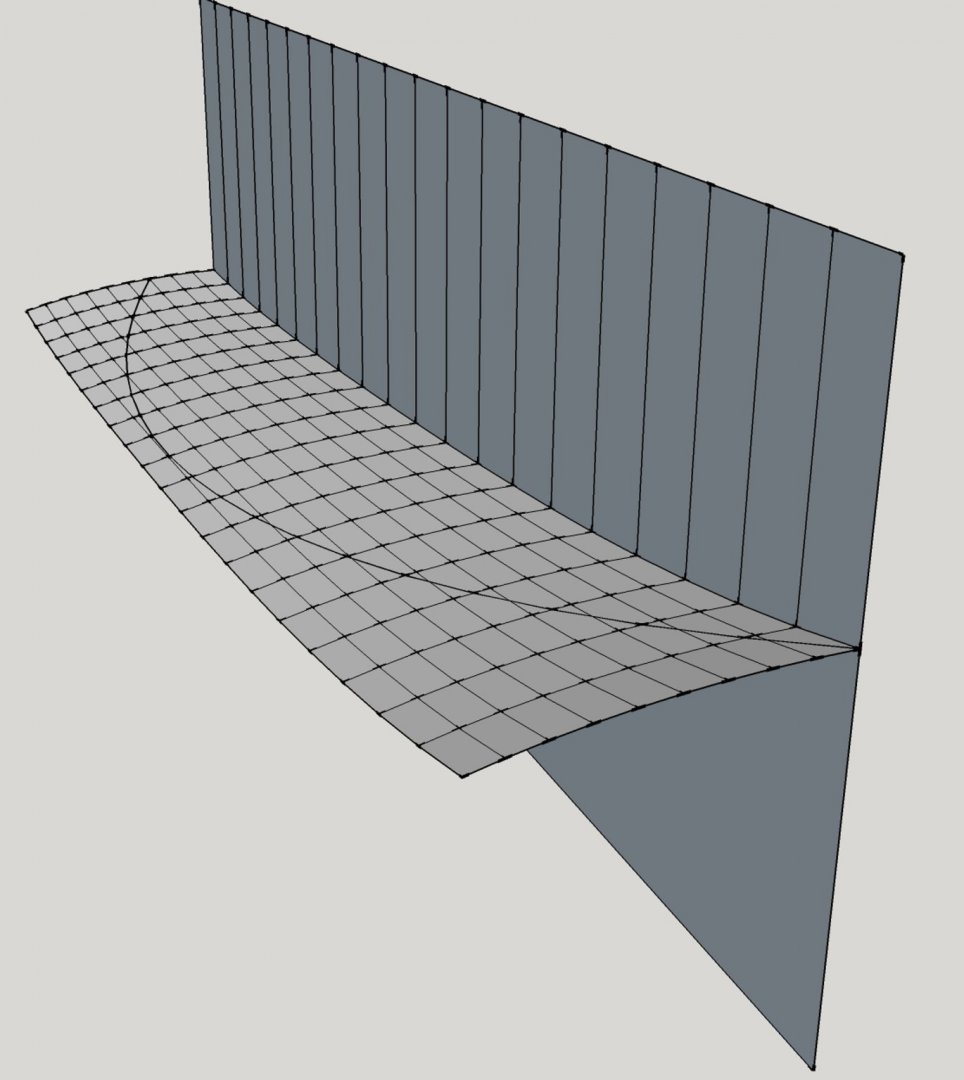
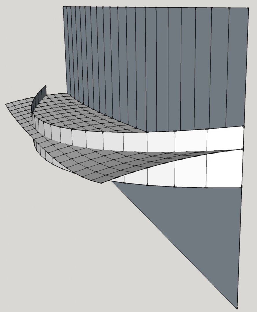
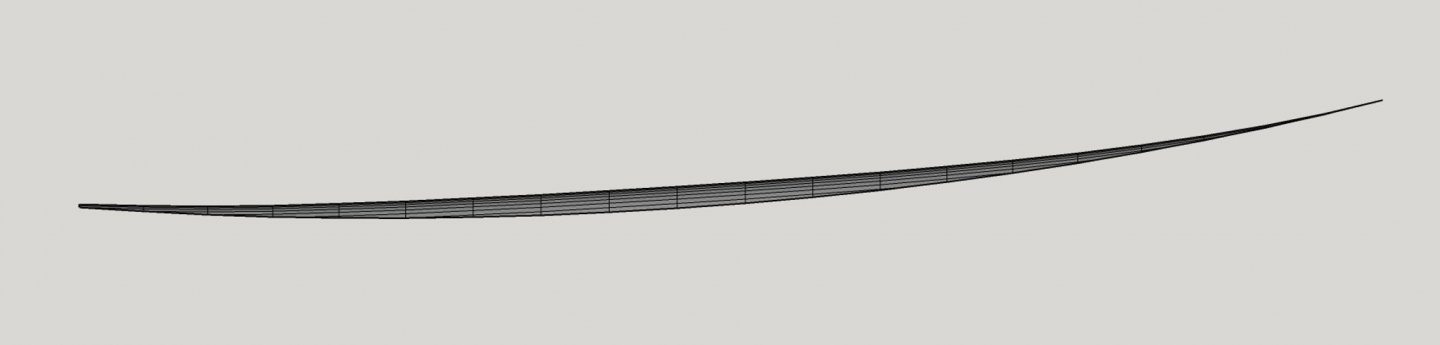
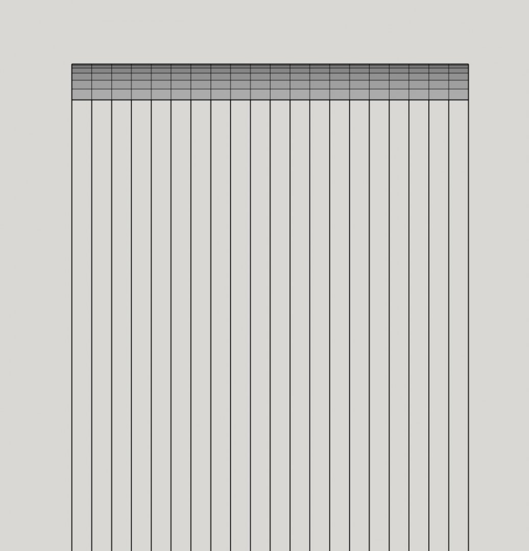
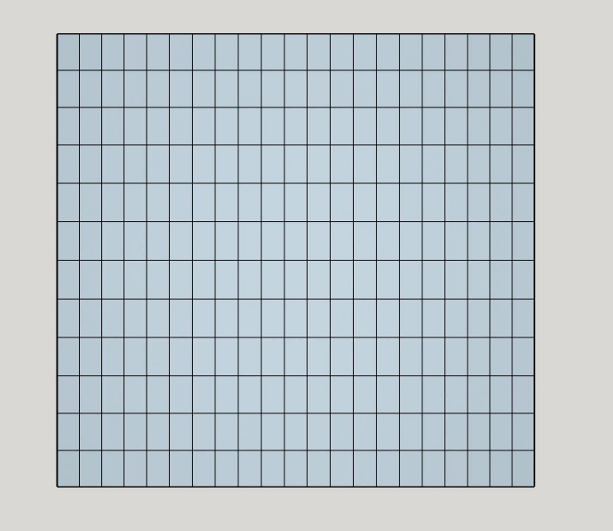
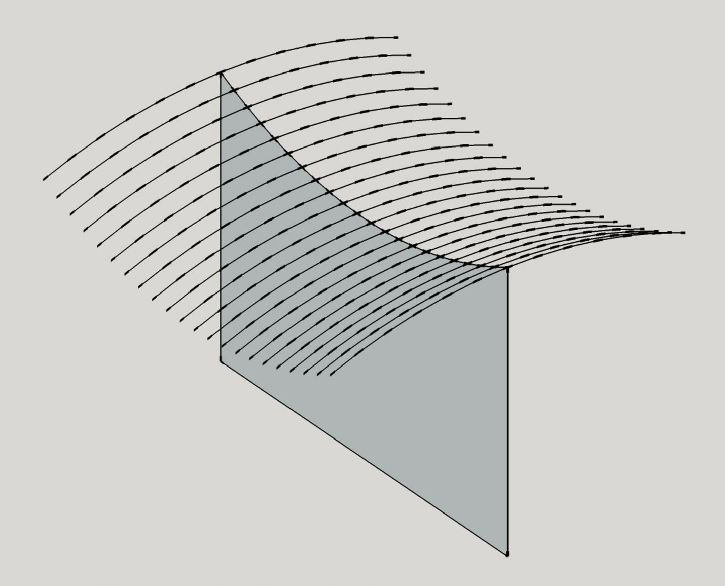
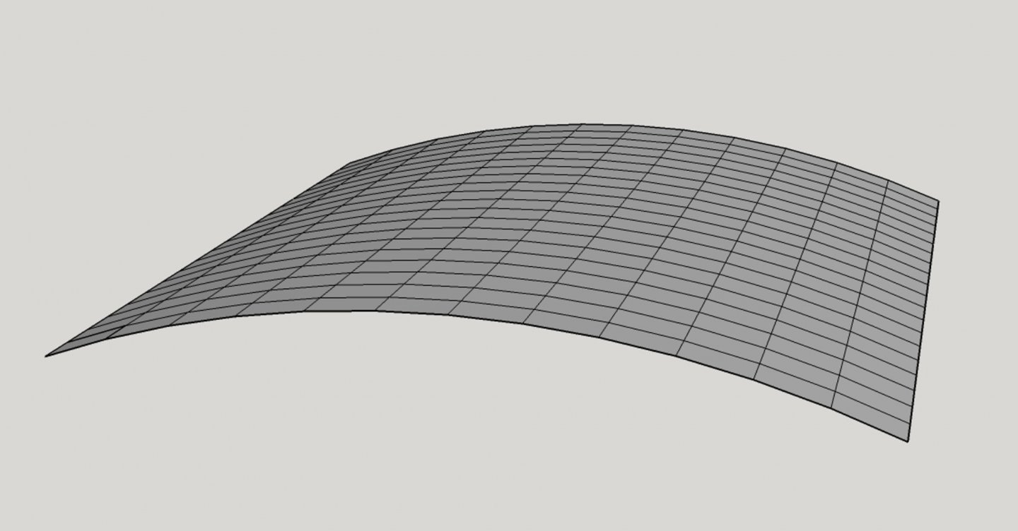
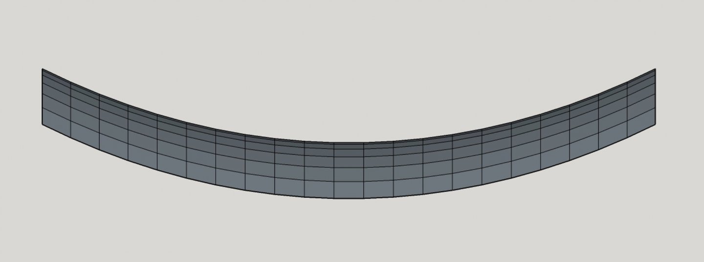
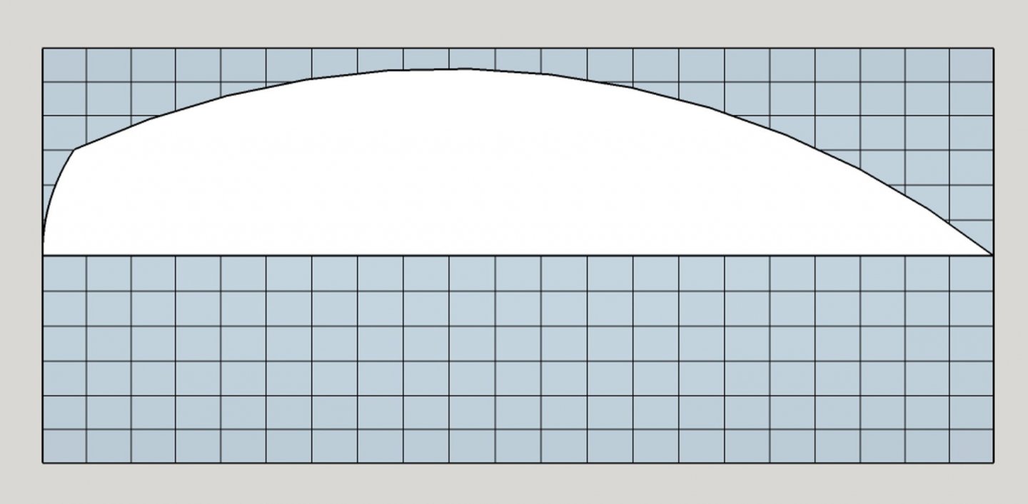
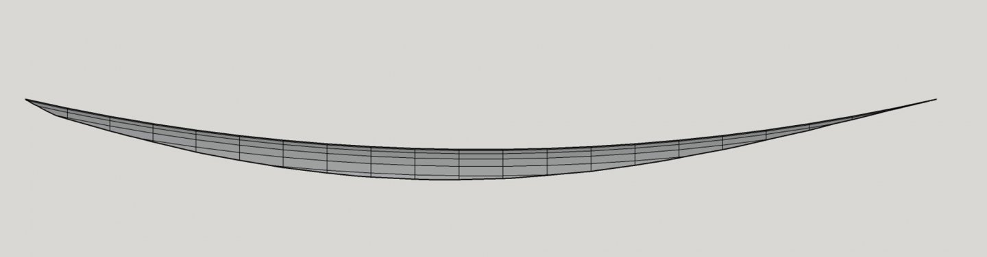
Not to beat a dead horse, I thought it would help to illustrate Phil's explanation to show that constant-camber deck construction actually works. Crothers et al claim that an upper edge of a cambered deck beam is a segment of a huge circle—too large to lay out on a lofting floor. So that is why the graphical approximations for a circle segment shown in earlier posts were developed. The following image shows a line of circles of equal diameter arranged along a vertical, rectangular plane. The edges of the circles adjacent to the rectangle represent the edge cambers of a series of deck beams arranged along a straight sheer centerline. This will be the basis for "constant camber." Now, please bear with me. All the following images were derived from a Sketchup model. If you connect the edges of the circles in such a way to create a surface on both sides of the reference centerline rectangle, this represents a cambered surface with no sheer. In Sketchup, you have to create a bunch of small rectangular faces to produce the surface, which I didn't illustrate at this point. However, taking a side view of the constructed cambered surface, it would look like this: The vertical edges within the surface are the included edges of the circles, or camber curves. The horizontal edges form the faces of the cambered surface. Note that these latter edges are all parallel with the straight centerline sheer—a geometrical certainty in a cylindrical surface. Let's remove the portions of the circles not included in the cambered surface to reduce clutter. This is a plan view showing the surface. (The deck/hull centerline is left-to-right in this view.) Again, the longitudinal lines that connect the individual deck beams (the horizontal lines) are parallel to the centerline of the vessel. Here is a perspective of the cylindrical cambered surface looking aft along the centerline. Obviously, the curvature of the camber is exaggerated for this discussion: Now, getting to an actual vessel deck, lets assume the centerline in the profile view is a generic curved sheer line. Then we reconstruct the same surface from that starting point. Again, the vertical rectangle with the curved edge represents the profile view of the centerline plane of the hull deck. Here, the cambered beam edges are arranged along the centerline sheer. Now, we create the cambered surface by connecting the nodes visible in the image with line segments (this is a process in Sketchup). This results in the "saddle" shape that Phil mentioned in his post. If we look at the profile view of this surface, we see that the longitudinal lines in the surface are all parallel to the centerline (sheer) curve. These lines could represent deck plank edges. They neither converge or diverge from the sheer profile in a constant-camber situation. So, how does this look in a real-world application where the deck beams are constrained by a hull? Let's take a hull-shaped "cookie cutter" and create a deck from this saddle shape that fits into a hull. I stretched out the cambered surface in the longitudinal direction to provide a more realistic proportion of length-to-beam. After cutting out the hull shape on one side, eliminating the parts of the surface outside the cookie cutter, and duplicating, reflecting and joining the two halves of the surface, this is what we have in perspective: Ignoring the facets, which are artifacts of the digital program, this surface represents a sweet and fair moulded deck. All deck beams have the same camber. Again, a profile view of this surface shows that all longitudinal lines on the surface are parallel to the centerline sheer. Note that the lower edge in this image is the outboard deck sheer line from which the rail line can be projected. However, to be perfectly honest, David (Druxey) reminded me that ship designers started with a sweet and fair rail sheer line, then established the positions of the outboard ends of the deck beams below that, and then from this information, developed the centerline sheer line as dictated by the widths of the deck beams and their camber. This is correct, but working the process in reverse of what was presented here still yields a fair curve without having to create separate cambers for each beam. I hope this illustrated explanation will help visualize what several of the contributors to this topic have been saying. Constant-camber geometry likely applied to vessels at least from the mid-1800s on, if not earlier, so modelers experienced with earlier vessels may be justified in having a different view of this issue. Cheers, Terry


-
Phil, Your perspective diagram is just what is needed to explain the concept of "constant camber" as it applies to deck form. I was considering using the term "saddle" in an earlier post in order to explain the essential shape of a ship deck where all beams had identical cambers along a curved sheer, but I was concerned that would just add to the confusion. Well done! Since some of the issue seems to center on the historical use of the term "camber," it's always helpful to go to the etymology of a word to understand where it came from. The etymologyonline.com source provides the following entry for camber: camber (n.) "convexity on an upper surface," 1610s, nautical term, from Old French cambre, chambre "bent," from Latin camurum (nominative camur) "crooked, arched;" related to camera. As a verb, "become slightly arched," from 1620s. Related: Cambered; cambering. I consider this website to be fairly authoritative. They provide a link to their list of principle sources, which is quite extensive. It is possible and even likely during the past 400 years that writers and draftspersons could have misappropriated the word, not fully understanding its origin, and applied it to situations not intended by its initial usage. We even see the same thing happening in more modern times. A cambered road surface is crowned to facilitate water runoff (✔️). But the word also now applies to banked race tracks (❓) as well as the design feature of vehicle steering mechanisms that facilitates restoring turned wheels to the straight-ahead orientation (⁉️). Tom, I must respectfully disagree with your conclusions. If you create a deck beam template with a particular round up or camber at the deadflat, then use that pattern for every beam forward and aft of deadflat arranged along the moulded centerline deck sheer, you will obtain a fair, curved surface. (See Post #15 in this topic, which illustrates this approach I used.) This is a mathematical necessity, as Phil noted. The length of the beams is determined by where they intersect the ceiling timbers (at least that's the way it worked for 19th century ships) but this in no way affects the moulded deck surface. It is true that the beams appear flatter near the ends of the hull, but their surfaces are still parallel to adjacent beams with the same camber, so the surface they form will be a fair one. I will defer to those who have studied ship construction in earlier periods where builders may have reduced the camber toward the ends of the ship, since the camber was less effective to shed water on shorter beams. But this wasn't a geometrical necessity, and eventually was superseded by the more standard practice of constant camber as stated in the references I have cited above. Terry
-
Hey Dean. My customer is this guy named CDR_Ret. He's neither rich nor values form over substance. He is really particular about substance. Not having ever built an actual model ship from scratch, I'm probably overthinking many of these details that would never see the light of day in a finished model. Since my nuclear engineering background was founded in following rules and specifications, I find it natural to review the basis for every detail that I don't have personal knowledge of. And since it is more than likely that I will never actually build a model of the ship I am researching, I hope to at least create the most accurate set of plans possible based on all available resources, so someone else can have that privilege. Sorry to have hijacked your thread. Did you find the answers you were looking for? Best wishes. Terry
-
David, Yes, that likely is the actual way the deck sheer line is created. The method I described reflects the process I had to resort to because Galilee's original plan's rail sheer wasn't fair to begin with. I suspect that a draftsman before the advent of 3D software may have had to resort to an iterative method to arrive at both a fair rail sheer and a fair deck sheer. Thanks for injecting a bit of reality into my comments. 😬 Terry
-
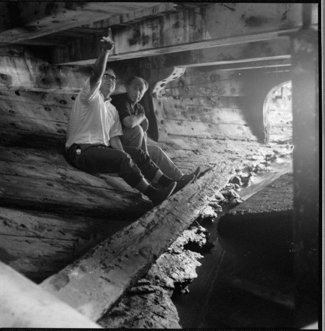
Reviewing the responses here, I am having some difficulty reconciling these views with what I have read in resources contemporary with the age of sail. Granted, I am not an expert on this topic, so please bear with me. First, dealing with camber. My understanding is that "camber" refers to the round up of the beam athwartships, not longitudinally. Camber is visible in the body plan, not the profile view. The curve of the moulded deck in profile is the centerline deck sheer. This definition of camber is confirmed in both Crothers' books and in various dictionaries. The term "camber" itself is not used in the Record of American and Foreign Shipping 1890, but the context of the word "crowned" referring to the shape of the deck beams is unambiguous. My understanding is that the American Shipmasters' Association (ASA, and its successor, the American Board of Shipping, ABS) were essentially American construction standards setters for underwriters similar to Lloyds of London. I'm not sure what Mr. Davis's point was in the Woodenboat article, but if the deck beams with a "constant camber" (meaning to me that all beams use the same camber template created at the deadflat body plan) are installed in the ship to create a fair sheer curve along the ship's centerline, then all deck planks laid parallel to the centerline will also have the same deck sheer. It seems to me that the sheer of the outboard rail is contingent on the intersection of the deck beams with the moulded hull surface, assuming a constant rail height above the deck is to be established. A sweet and fair rail sheer in profile depends on the deck camber, the moulded beam of the ship, and the shape of the hull. If each beam had its own round up based on its length, then the deck planks would not provide a uniformly fair surface. Perhaps I have misunderstood what was intended in the above comments. In attempting to reconstruct my grandfather's ship's main deck using the principles Crothers stated and the ASA's construction standards, the following image shows how the moulded deck's surface lies true and fair. All beams have the same camber. The gaps resulted from variations in beam spacing. The deeper beams are in way of hatches and masts per the ASA Record...-1890. Brigantine Galilee's reconstructed main deck beams, constant camber (2-1/2 inch roundup). Model in DELFTship. Dean's concerns about introducing the "spring" in deck beams in a model are correct—up to a point. There is no reason to include this feature in a model because the stresses relating to an actual ship aren't present. In any case, the forces involved springing a beam compared to the other stresses in the hull were minimal. A 40-foot beam would be sprung only 4 inches (0.83%), and that would be included in the total design camber for that beam. Beams near the ends of the ship would have little or no spring. Recall that the purpose of the beam spring and stanchions is to reduce the weight of beams on the sides of the ship by transferring that weight to the keel. Regarding the shape of the beam bottom surface, it is pretty clear from both Crothers and the ASA Record... that the bottom of the beams (at least merchant ship beams) in the latter 1800s were not curved. From the Record of American and Foreign Shipping-1890, it states "The beams may be reduced in moulding one-fourth at their ends; the underside straight, and upper side crowned." (p. 38, emphasis added). The bottom surface of the beams being flat seems to be evident in a photo taken of the Galilee's hold in the 1960s, 70 years after she was built. I'm not sure that any "spring" in the beams would be evident from this vantage point. Also, considering that the keel is basically gone at this time in the vessel's history, eaten by ship worms, the spring, if present, would have been released. Derelict Galilee's hold, showing main deck beams, hold ceiling, beam clamp, and knees (c. 1965). A question I have is this: Though the beam bottom surfaces were straight (not crowned), were they horizontal? Or were the bottoms angled fore and aft to follow the deck sheer? This would be significant only at the ends of the ship. Reconstructed forward main deck beam in Galilee with a horizontal bottom surface (perspective looking starboard toward centerline). Only the port half of the beam is visible in this image. Same deck beam but with the bottom surface following the local moulded deck sheer line. Based on the quotation from Crothers in my previous post, I would say the intent would be that the lower surfaces of deck beams were horizontal. This would also reduce the work in fabricating beams and simplify installing the beam stanchions to bear against a perpendicular surface. Thoughts? Terry

-
Please permit me to put my oar in, since this topic has recently been of some concern for my research project. I have finally found some contemporary and near-contemporary wooden ship construction rules for my late-19th century brigantine merchant. William Crothers, in his book American-Built Freighters and Packets of the 1850s, makes the following statements: "The true form of the camber curve is the arc of a circle of great radius, which is difficult to draw due to the space required." (p. 55) "Three methods of developing a proper curve for deck camber—one mathematical, one geometrical, and one natural—are illustrated [in Figure 3.6]. In all cases, the maximum moulded breadth of the deck is the database." (pp 55, 57) [Frankly, the first two methods he shows appear to be two different geometrical methods. The third is springing a long uniform wooden batten between marks at the ends of the reference beam on the lofting floor and marking the curve at the required roundup.] Brackets are my additions. "This [the deck camber] was arbitrary and was commonly 6 to 8 inches in forty feet." (p. 57) "The established camber curve, or round up, is constant throughout the length of the vessel." (p. 57) The following passage was completely new to me when I first read it. It refers to "springing" the deck beams. "An attempt to spring a [straight] beam, which might be moulded eight to ten inches, to the maximum height of camber curve, would exceed the elastic limit of the substance of the beam. The maximum allowable spring in a beam is about one-eighth of an inch per foot of length, but this figure is reduced to one-tenth of an inch in actual practice. The solution was to cut a portion of the camber into the beam itself on the upper side and, if necessary, on the under side. In any case, the required moulded depth of the beam had to be retained. (p. 57) [Farther on, he explains that the beam is placed in the ship and fastened to the clamps, then jacked up in the middle to attain the required camber. A permanent stanchion under the beam is then installed, which transfers some of the weight of the beam to the keel below, relieving the load in the ship's sides.] I discovered in the Record of American and Foreign Shipping-1890 that deck beam scantlings were determined by vessel tonnage. Beams adjacent to hatches or mast partners were 10 percent larger than standard beams. The underside was to be straight, and cambered only on the upper surface. All beams in the vessel (for a given deck) were to be maintained throughout the vessel. An exception was made that beams toward the ends of the vessel could be reduced by one-eighth throughout the length of the beam. A later standard identified the "ends" of the ship to be one-fifth the length from the stem and stern post. One question I haven't quite answered yet is whether the bottom surface of a beam is parallel to the moulded sheer of the deck as the top surface would be, or is it parallel to the waterline? Crothers suggests that the latter is the case. He writes, "At the beam ends, in way of the clamp, the lower surface of the beam was snaped to rest flat, or horizontal, on the clamp. If necessary, the clamp itself was trimmed to accommodate the end of the beam." (p. 207) This makes sense only if the lower surface of the beam was parallel to the waterline. Any thoughts on this information. None of the foregoing applies to wooden warships, sadly. Terry
-
Mike, as others have said, laser cutting in conventional use applies only to cutting essentially 2D objects from 2D patterns. The 3D model is constructed from these parts. If 3D laser ablation is actually a thing, it is a very specialized process. Computerized 3D manufacturing involves either additive (i.e., 3D printing) or subtractive (i.e., multi-axis milling) processes. Shapeways offers photoactive additive manufacturing methods involving lasers, but I suspect that isn't what you are looking for. Terry
-
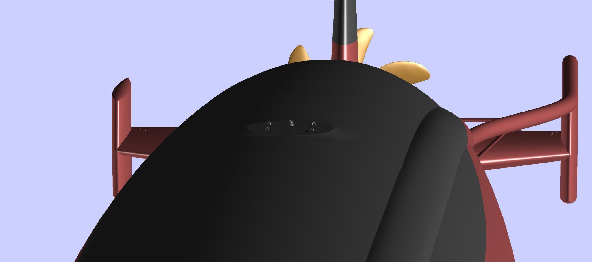
Working on the escape trunks, now that the grandfather journals have been delivered to all the cousins and siblings... The Sturgeons had two escape trunks. These acted like airlocks in spacecraft to allow emergency egress in case the boat was bottomed for some reason. The only difference is that there is high-pressure sea water outside instead of a vacuum. Basically all US submarines following WW II had the capability to mate with the McCann rescue chamber. This required a flat surface surrounding the upper escape hatch fairing, which was equipped with a haul-down bale, external hatch operating gear, and, later, anchor points for the Deep Submergence Rescue Vehicle (DSRV) snubbers. The flat landing surface on the albacore/cylindrical hulls had to be faired into the hull shape. So, I tried to illustrate all of these features in this model. The haul-down bale was actually attached to the emergency buoy cable, which was manually released from inside the ship. The buoy carried a cable to the surface of the ocean, to which the rescue device was attached by divers. The DSRVs used the cable to visually guide the vehicle to the stricken sub. The DSRV would mate to the hull above the hatch, then attach snubbers to the four rings to steady the vessel before blowing the skirt dry and entering the sub. In truth, this is a lot of surmising, since none of my boats ever went through a DSRV drill or deployment exercise. Location of the fore and aft escape trunks. The forward trunk was in the bow compartment and the aft trunk was in the engineroom. This is the forward escape trunk landing area. I had difficulty modeling these because I don't recall them being so prominent. But there were other things surrounding them like safety tracks, so perhaps they were. The aft escape trunk. Since the upper parts of the escape trunks and hatches were located within free-flooding areas and/or ballast tanks, there were a lot of other pieces of gear associated with them that couldn't be installed in way of the pressure hull. These included line lockers, the emergency buoy, retractable cleats, towing fairleads, hydraulic capstans, and so on. Given time, I may actually get to those. Terry


-
Exploring FreeCAD for ship modeling
CDR_Ret replied to TonyM's topic in CAD and 3D Modelling/Drafting Plans with Software
Tony, that looks simply ... agonizing. I can appreciate how much labor went into those lines. Terry -
Ships vs Boats
CDR_Ret replied to Mike from Aus's topic in Using the MSW forum - **NO MODELING CONTENT IN THIS SUB-FORUM**
Keith, are you a lawyer by any chance? -
Ships vs Boats
CDR_Ret replied to Mike from Aus's topic in Using the MSW forum - **NO MODELING CONTENT IN THIS SUB-FORUM**
Just don't call a ship a boat, unless it's a submarine! I don't know how many articles I read over the past several weeks about the "boat" stuck in the Suez Canal! 🤨 -
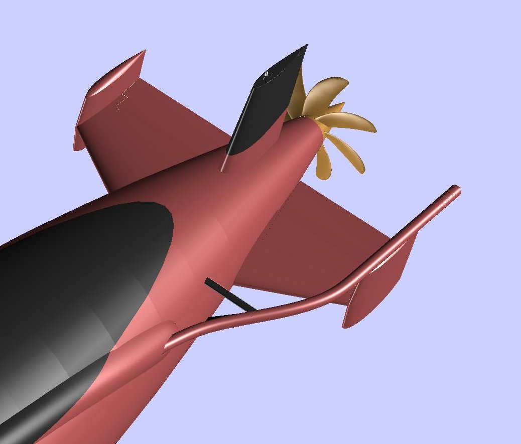
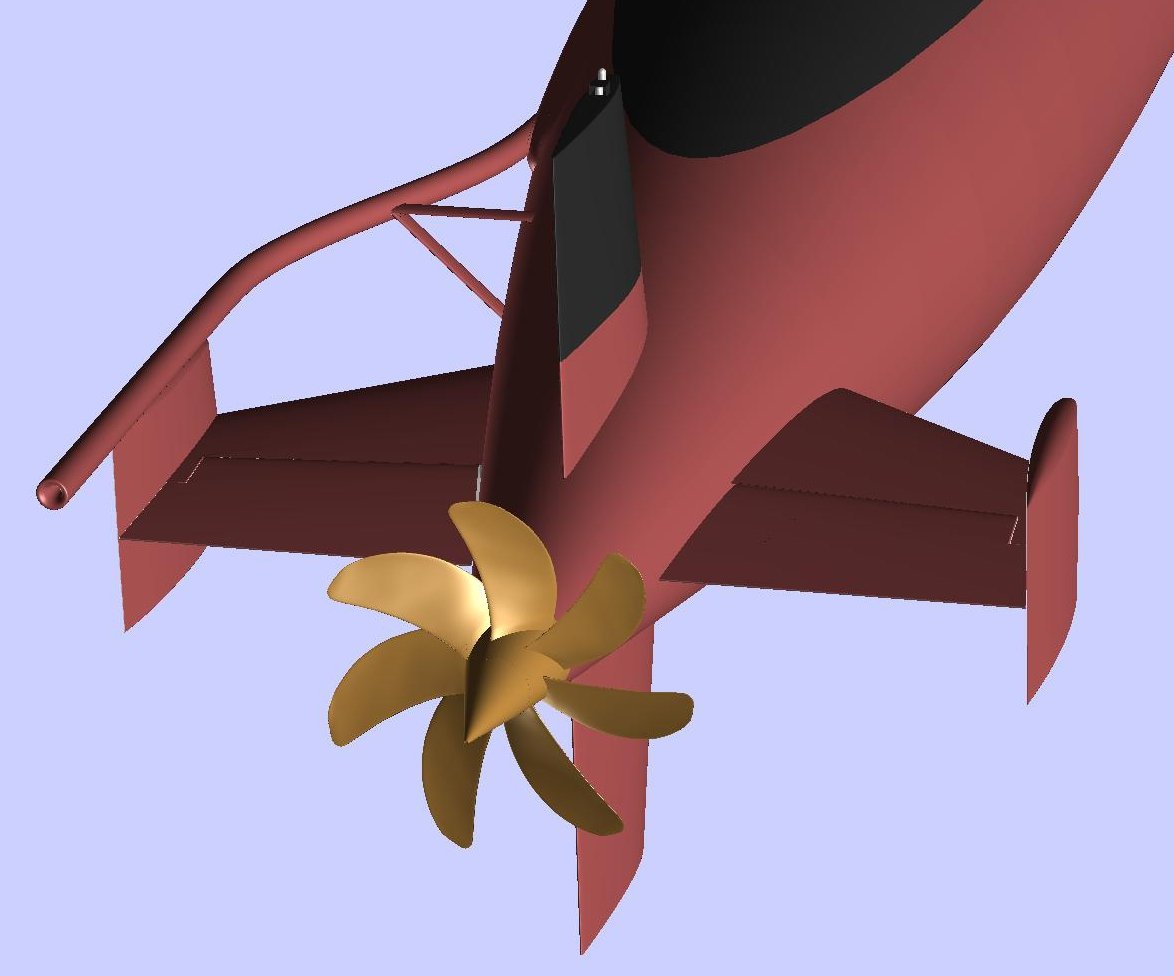
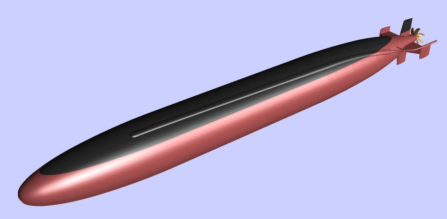
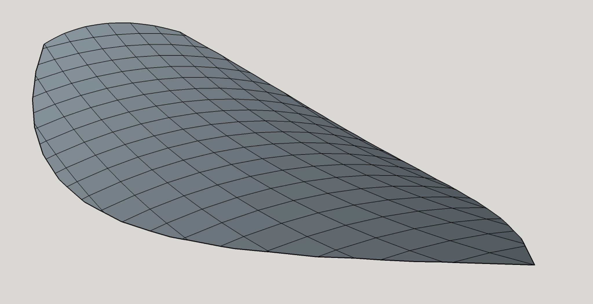
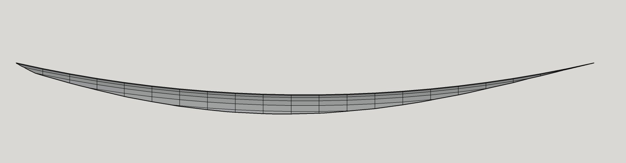
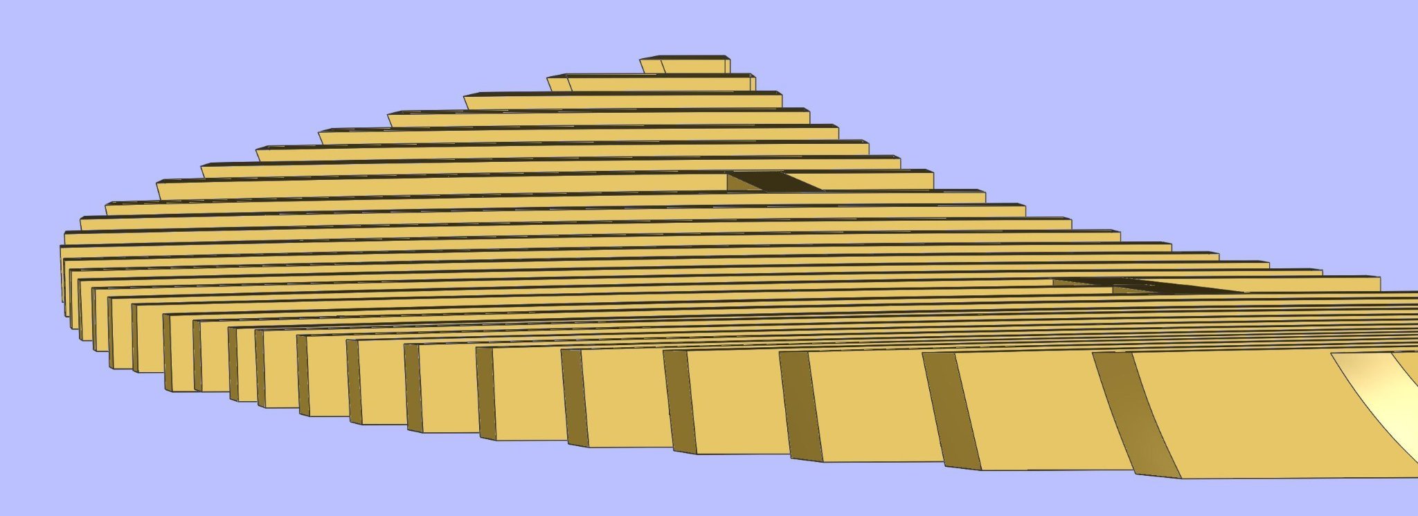
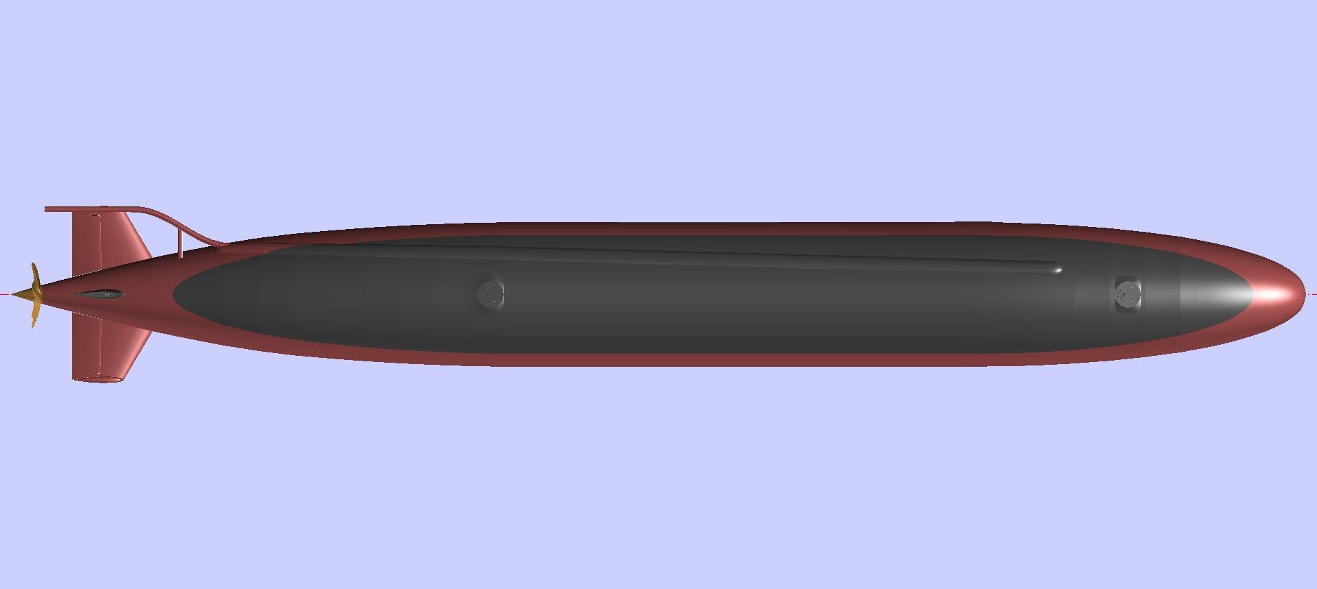
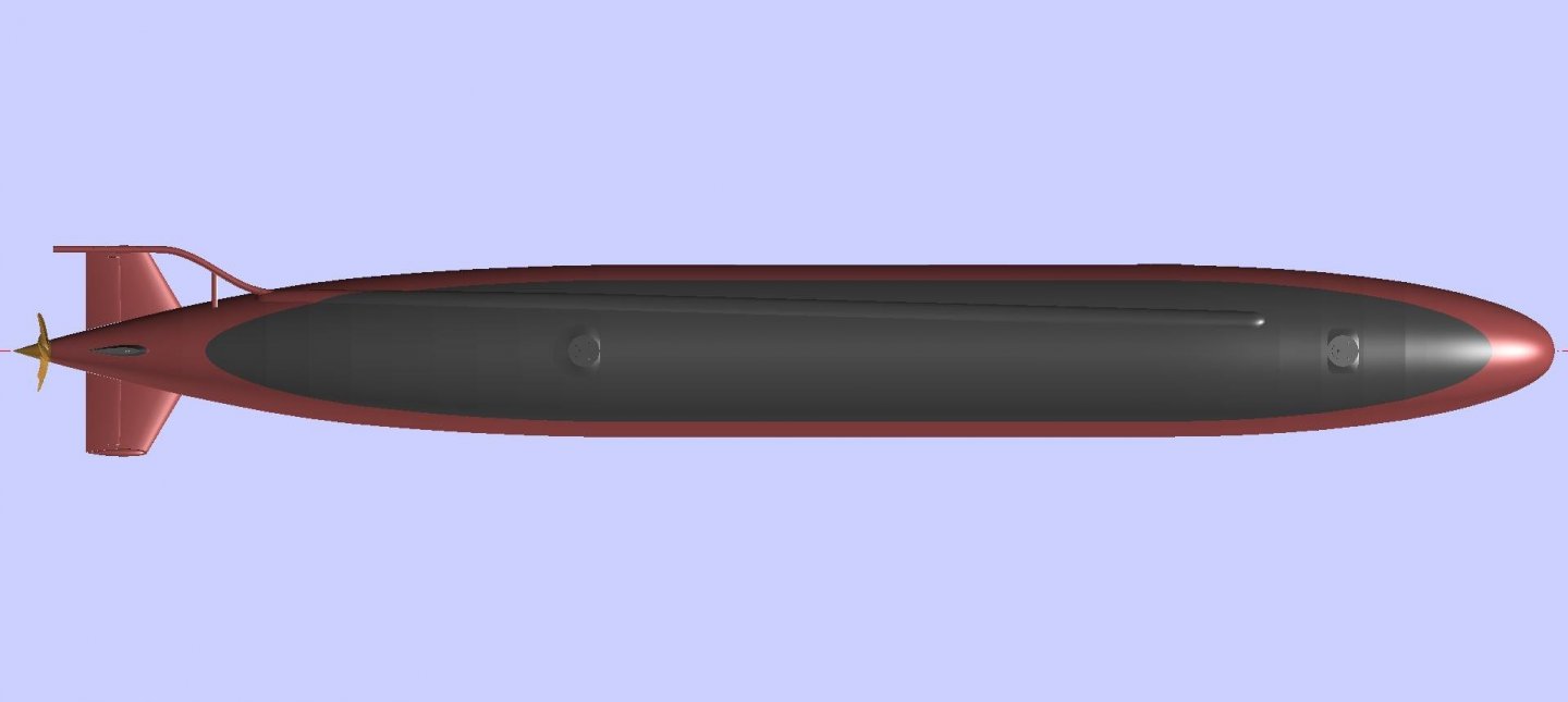
Continuing to work from aft to forward, today is the towed sonar array tube and faring. The Sturgeons were already being constructed when the US submarine force received their towed arrays. These sonars were towed a long distance behind the ships to remove the receivers from the vicinity of the largest sound source in the area—the towing submarine itself. So the early towed array systems were add-ons for the Permit-, Sturgeon-, and the Los Angeles-classes. (The towed array systems for the Sea Wolfs and Virginias are totally internal.) The handling gear for the array cable was installed in a forward ballast tank and the sonar array itself was stowed in a long tube that led to the stern planes. The "flushing tube" laid against the hull and was covered by a low fairing topside. The aft end of the tube had to extend far enough aft so that when the ship executed a sharp turn, the array wouldn't be cut off by the prop. (The Soviets solved this problem by putting their array and handling gear in a pod on top of the vertical stabilizer of the rudder.) The sonar tube was called the "flushing tube" because the array was deployed and retracted by pumping water through it to "flush" the array out and lubricate its retraction. The most difficult part of modeling this component was the topside flushing tube fairing, which twists in three dimensions as it lies along the hull. Sturgeon Class Towed Array Flushing Tube and Support Aft view of the Towed Array Flushing Tube Towed Array Fairing Modeled in DELFTship Terry