CDR_Ret
-
Posts
660 -
Joined
-
Last visited
Content Type
Profiles
Forums
Gallery
Events
Everything posted by CDR_Ret
-
And as you have discovered, we are more than willing to misread a post if it garners a laugh! 😁
-
This news item is being covered on several websites. The UK Daily Mail seems to have one of the more complete write-ups, though it doesn't provide much detail. Several videos on various sites include interviews with the divers. This piece claims that the wreck's contents upend the idea that after the Islamic conquest of the Middle East, basically all trade with Western Europe shut down. Not sure why that was the case. Traders always seem to ignore geopolitical differences. We see that even today. Terry
- 1 reply
-
- 2
-

-
Well, for the most part, that aspect of the job was actually one of the more meaningful roles I had to fill in off-crew, and I was glad to assist the families experiencing problems when their husbands/fathers weren't around. And it wasn't like I was alone. I had the assistance of the on-crew's ombudsman, and the CO, XO, and COB's wives, who were indispensible for handling on-crew family problems. I was more like the traffic cop, directing issues to the best-qualified to help. It was getting phone calls in the office from 16-year-old girls crying because they had spent all their husband's money that irked. And that happened more than once! My wife had more issues dealing with our own crew's wives... Sorry, didn't intend to hijack the welcome aboard.
-
Well, I'll answer your question by describing what I liked about SSNs, first. When not on deployments, attack boats conducted what we called weekly ops. Routinely, underway on Monday, back in port on Friday, more or less. If you were lucky, you didn't have the duty over the weekend. Great for family life. SSNs were often tasked with interesting things like weapons evaluations, supporting fleet exercises, providing ASW services to the skimmers and VP assets, under-ice training, preparing for type-commander inspections, etc., etc. Occasionally, a boat would be scrambled to investigate a SOSUS contact or whatever. A very interesting and busy life. US boomers had a set schedule. 60 days in home port/90 days deployed--over and over again. "49 days and a wake-up." The time at home port was spent training, getting required schools, a little leave if possible. As XO, I also had to deal with the family issues of the deployed crew. You wouldn't believe how many teenaged sailors married even younger girls who had no clue how to budget. Spent all their husband's advanced pay after only a few weeks! When deployed, everyone got sick during the month-long refit due to long work hours, then we went to sea. We literally drilled holes through the ocean trying to avoid detection, which was our primary peacetime mission. Of course the crew kept busy with qualifications and drills, but after 14 years in tactical and intelligence work with SSNs, it was pretty boring. The two-crew concept also tended to lead to leaving problems to the other crew, which resulted in some acrimony between crews. Boomer crews also tended to be made up of mostly long-term boomer sailors, who often had a starkly different views of navy life and even worldviews compared to SSN sailors. Just some thoughts.
-

Redoing Oseberg
CDR_Ret replied to KrisWood's topic in CAD and 3D Modelling/Drafting Plans with Software
And make sure you provide clear attribution in your text, and even a link to the original source. Terry -
Hey Glenn, Over my career, I served in a 637-class long-hull, a 637 short-hull, built a 688, and served as XO in several boomers during a decommissioning of one. Didn't like the boomers...
-
Swivel guns
CDR_Ret replied to tlevine's topic in Discussion for a Ship's Deck Furniture, Guns, boats and other Fittings
In the FWIW category, research suggests that the average male height in the 1600s and 1700s was about 66 inches. So assuming chest height is about 2/3 of that, or 44 inches, that would give a target value for the swivel gun mount height. 🤔 Terry -
Hey Glenn. Welcome aboard! Retired (US) submariner here. Looking forward to viewing your construction of your father's ship. Scratch would be definitely doable. Terry
-
I also received a "The connection to modelshipworld.com is not secure You are seeing this warning because this site does not support HTTPS." message in my Chrome browser when I just logged onto the site (1524 MST 7/26/2022). So there are still some issues to take care of.
-
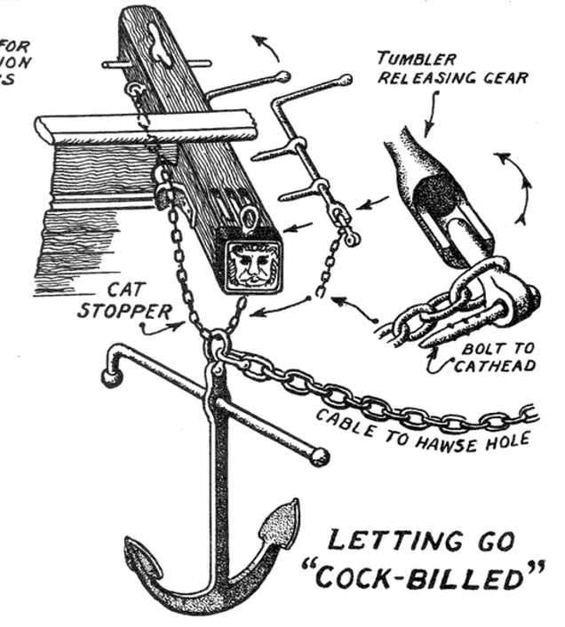
@BANYAN, yes sir, any information will be appreciated. I'll PM you with my email address, if that would be more convenient. None of the DTM (Carnegie Institution Department of Terrestrial Magnetism) photos from their charter period are clear enough to discern the details of such devices. I am having trouble even figuring out from the photos what were the cat stoppers, cat falls (if used), and the other components involved in catting and letting go an anchor in this period. There appears to be only a single sheave in the cathead and no cat blocks. Just a bight of chain through the anchor shank ring. I found this image at a Pinterest account online—no attribution—showing a detail of the mechanism @Jim Lad provided earlier: This arrangement was supposedly representative of ground tackle gear around 1850. None of my photos reveal any cleats or eyebolts near either end of the cathead like this diagram shows. Terry
- 5 replies
-
- 1
-
-
- anchor cleat
- brigantine
- (and 3 more)
-
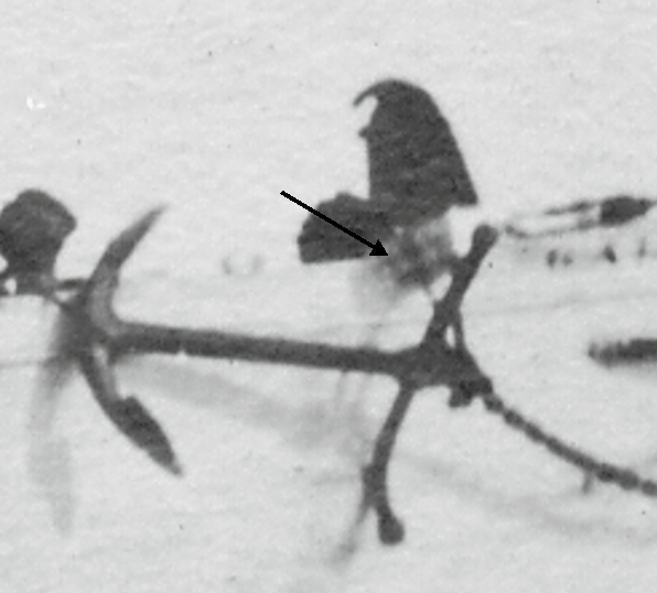
As it turns out, one photo of the ship I have in my collection provides a suggestion that Galilee indeed had some sort of anchor release mechanism similar to that provided by @Jim Lad. This photo is the only one that shows the aft side of the cathead with sufficient resolution to make it out. The arrow points to the probable anchor release gear installed in the brigantine Galilee. (Photo courtesy of Carnegie Science Library, c. 1906–7) Another interesting detail to include in the plans. Thanks Jim! Terry
- 5 replies
-
- 1
-
-
- anchor cleat
- brigantine
- (and 3 more)
-
Hey @Jim Lad. Thanks for this information. This will be something else to look for in the ship photos, since I'm sure releasing a 600-pound anchor was not a trivial task! I was mainly trying to nail down how the anchor was secured for sea, since I am finishing up modeling the various deck gear and fittings in the forecastle of my ship plan reconstruction. But the release mechanism is certainly something to ascertain as well. The USNA textbook had some diagrams of similar gear to consider, though I'm not sure how applicable the type would be to a merchant ship. Terry
- 5 replies
-
- 2
-
-
- anchor cleat
- brigantine
- (and 3 more)
-
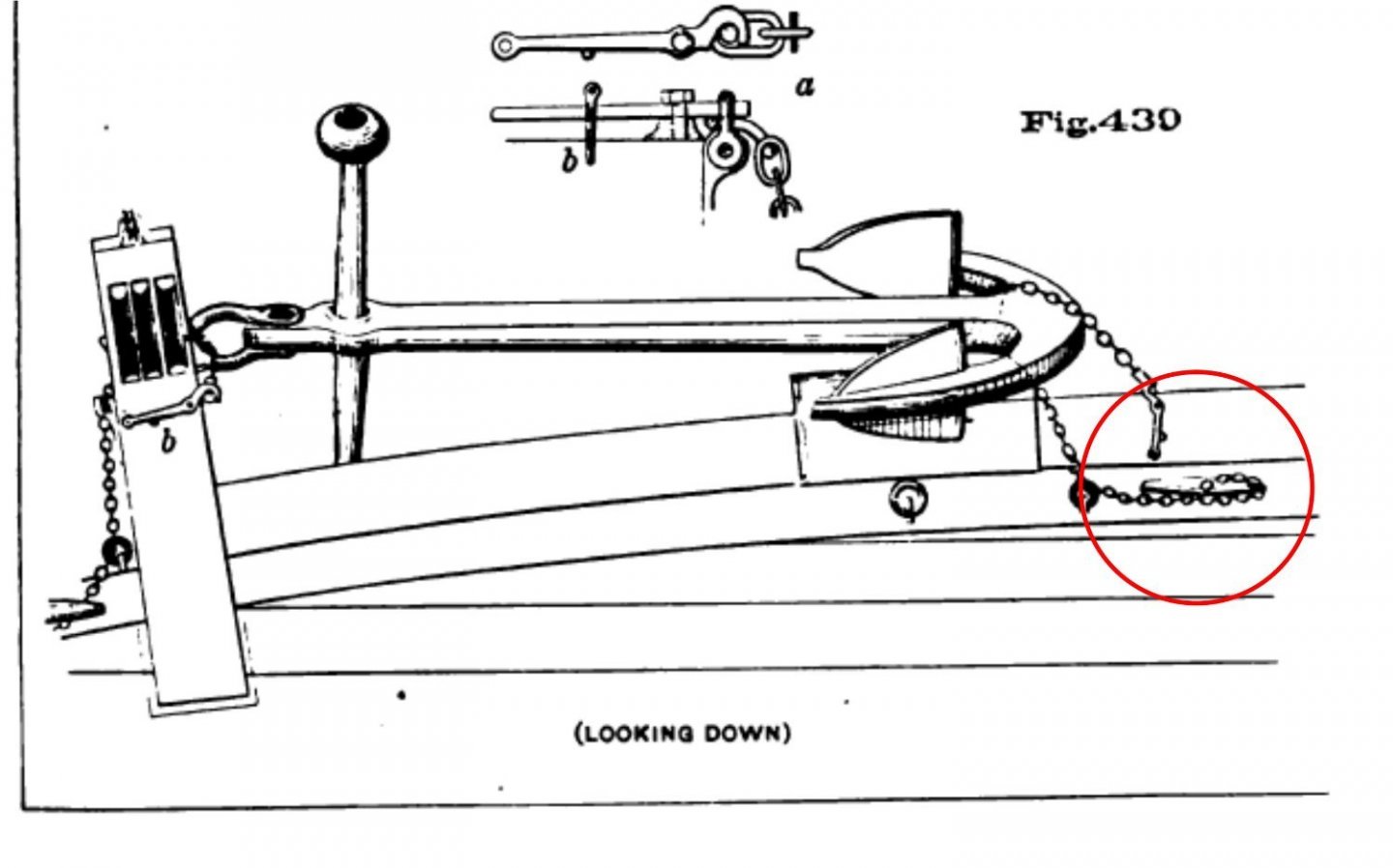
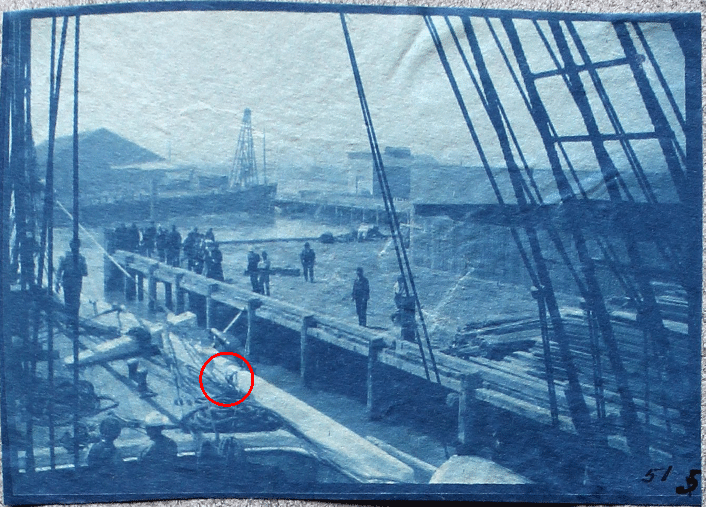
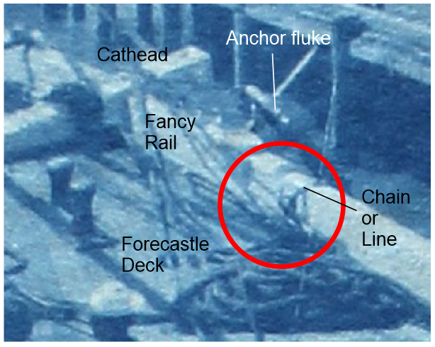
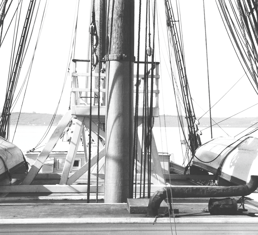
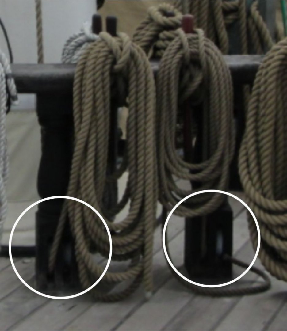
This topic pertains to the proper securing of bower anchors in latter 19th-century merchant ships. I have several poor-quality photos of the foredeck of a brigantine merchant ship (the Galilee) taken sometime during 1905–1908, showing how her anchors were secured when underway. This is probably the best of the lot. Photo showing the brigantine Galilee being fitted out as a geomagnetic research vessel in 1905, probably somewhere in the vicinity of San Francisco Bay, California. The circled area is where the chains/lines securing the lower end of the anchor were tied off. (This and following photos Courtesy of the Carnegie Science Library.) Closeup of the area circled in the above photo. I am in the process of adding the remaining deck furniture and fittings to my digital model of Galilee. My questions pertain to the size, shape, and orientation of the cleats evidently used to secure the lower end of the anchors. What would be the size of the cleat? I've seen the rule of 1 inch of cleat length per 1/16 inch of line diameter. However, in many diagrams showing stowed anchors, it is small chain that was used for this purpose. So, what is the rule if chain is used? Galilee's anchors would have been a minimum of 600 lb. each, about half of which would have been borne by the anchor cleat. Would this have been a factor in selecting the cleat size? Determining the likely shape of the cleat is important for a historically-accurate model. I have found a source of so-called "antique" cleats here. The shapes are quite varied as one can see. Would the type most likely be just a basic cleat such as this one? I have read about—and also experienced—the proper orientation of lines taken to mooring cleats. Typically, the line secured to a cleat should run horizontally perpendicular (or tangentially) to the cleat. Cleats are weakest when the tension pulls upward. So would a cleat securing an anchor likely be bolted to side of a rail or to the deck adjacent to the rail? The latter configuration would result in a more upward tension. However, Figure 430 in Plate 94 of the USNA's Text-book of Seamanship (Luce, 1884) suggests this could have been the case. Diagram of the method for securing a bower anchor in a mid-19th-century warship from the cited USNA reference. The circled cleat appears to be fastened to the deck or a waterway. (The image is found in Plate 94 located between pages 246 and 247.) Any comment or directions to other sources to resolve these questions would be very much appreciated. Terry
- 5 replies
-
- 2
-
-
- anchor cleat
- brigantine
- (and 3 more)
-
Thanks @wefalck and @popeye2sea. I had already begun leaning toward blocks shackled to eyebolts on the deck under and inside of the fife rails. One belaying plan even showed the eyebolts. in that location. Most of the iron/steel rigging elements aloft were all but eliminated by the second survey cruise (1907) to reduce the vessel's magnetic constants to the smallest magnitude possible. However, some items simply couldn't be removed because they were irreplaceable. Terry
-
Thanks for these inputs, everyone. And thank you Alan for the files you sent today. I wasn't planning on getting into rigging at this point in the plans reconstruction process, but figuring out the fife rails sort of dragged me in. Even with this information, I'm afraid, as the good doctor said, it will be a coin toss as to what was actually the case. The DTM photos show a lot of lines belayed to the bulwark pin rails; fewer lines leading to the foremast fife rail. So I will try to do my best and find a logical place for every line of running rigging when the time comes. To make things even more difficult, this ship was originally rigged with wire standing rigging, and chains for a lot of the sheet and halyard pendants. All that was removed for the magnetic expeditions to reduce the magnetic constants of the ship. The crew even cobbled together some additional foremast back stays because the channels weren't positioned properly for rope stays. Terry
-
Actually, I think you were correct in the first place. Halyards lift spars and sails, while sheets are attached to the sails and booms to control the angle of the sails. I haven't rigged a ship model since I was a teenager when I built Revell's USF Constitution back in the 1960s. And I was briefly certified to sail boats loaned out by the Navy Rec Facilities over 30 years ago. And submarines don't have running or standing rigging! I have forgotten more sailing terminology than I remember these days. I've been so involved over the past six or seven years trying to simply sort out the structure of the Galilee that I haven't been too concerned about the ship's rig.. Terry
-
Alan, I really do appreciate your input. In fact, if those sources show an association between a particular line of running rigging and the fiferail sheaves, that could be useful information. My concern, which was also echoed by John, is that rigging evolved so quickly during the latter 1800s, that trying to make a comparison between ship rigs separated by even two or three decades would likely be a problem. What I need to know is, if fiferail sheaves were used, what parts of the rigging were involved, how did the lines run, and were these common on particular kinds/and or sizes of ships? Terry
-
@AON and @Jim Lad, thank you for your responses. Alan, the references you cited are both several decades prior to the Galilee's construction and for ship types that probably don't apply to the smaller hyper-efficient/economic vessels late in the age of sailing merchants. (And I do not have any of the books in my library in any case.) Galilee herself was replaced by steam merchants on the San Francisco to Tahiti run before she was converted to a fishing vessel, so we are talking about the very last gasp of the age of sailing merchants. John, you bring up very good points regarding potential line handling options. Sadly, I have no photos and no plans showing how the halyards for the lower spars were rigged. If there are any diagrams available of latter 19th-century rigging practices, those would be particularly valuable. The ship had only 10 crew, 8 of which were ABS, so she would have been rigged for maximum efficiency. However, you have forced me to look more closely to the lines in the photo in my last post, and there is, indeed, a block attached to a port (right-side of photo) line that obviously is connected to another block/sheave below it. So perhaps we are making some headway here! Terry
-
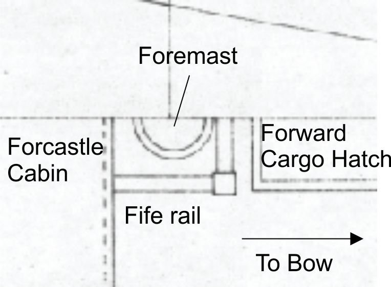
This is a research question on the structure and arrangement of fife rails constructed in smaller American merchant ships of the late 19th century. This question specifically pertains to the 1891 American West Coast brigantine packet ship Galilee, which is the subject of my topic found here in the Model Ship World forum. I specifically wish to understand the basic structure of a "partial" fife rail. Galilee’s original forecastle was constructed just aft of the foremast and so close to it that the sides of the mast’s fife rail evidently were attached to the forward bulkhead and were spanned by a transverse rail forward of the mast. Two corner posts evidently supported the forward section of the rail. No details as to the number of belaying pins or other features of this structure were provided. The following image was taken from the plans of Galilee produced by G.C. Berger of the former Pacific Marine Research Society* in San Francisco sometime during the mid-1930s or later. The foremast fife rail in the brigantine Galilee from the plans of the ship produced by G.C. Berger some time after the mid-1930s. I obtained this plan through the National Park Service in San Francisco One feature often seen in online photos and illustrations of fife rails is the presence of sheaves in the corner pedestals. Were these sheaves associated with specific types of running rigging that would be applicable to the square-rigged foremast in a brigantine? Would they have even been required for a relatively small packet ship? Cropped photo of the mainmast fiferail sheaves in USS Constellation, Baltimore Harbor, April, 2012. (Photo by Joel Abroad via flickr. Some rights reserved.) The following is the best photo I have of Galilee showing the various halyards, etc., that were evidently secured at the unseen fife rail. Since I am not really conversant about the kinds of running rigging such a ship would have, I can’t tell what each of these lines would go to. Would any of these have required sheaves in fiferail pedestals? Lower foremast of the brigantine Galilee showing the few lines of running rigging leading to the fife rail at its base. Most of the upper running rigging lines ran down to the main pin rails through thimbles(?) attached to the shrouds. (Courtesy of the Carnegie Science Library, c. 1906) Any assistance finding illustrative examples of such a fife rail would be appreciated. I have already done due diligence in trying to find examples on the Web and within the MSW site using keyword and image searches, but there is very little information on this topic and virtually nothing showing the kind of fife rail I am looking for. Thanks. Terry *The "Pacific Marine Research Society" was formerly called the "Pacific Model Society," whose founding was "to encourage the preservation of Pacific Coast maritime lore." ( From the Senate committee record Maritime museum; Stones River National Battlefield; Western Historic Trails Center; and Pinelands National Reserve Visitors Center: hearing before the Subcommittee on Public Lands, National Parks, and Forests of the Committee on Energy and Natural Resources, United States Senate, One Hundredth Congress...Vol 4; GPO, 1988.) This is the only reference I could find to the organization itself on the Internet. Some records from the Society remain.—RTE
-
Hello Doug and welcome to MSW! After my commissioning into naval aviation in 1973, I was assigned to an A-7E squadron as a non-flying intelligence officer. Made several det deployments to Fallon for pre-deployment workups. Never made it into town, but according to my aviators, the main attractions were bars and houses of ill repute. Go figure. I imagine all that has changed, and for the better, I'm sure! In 1975, I got my heart right and switched to nuclear submarines....
-
That is part of the reason I sold my 40-year-old 10-inch Delta contractor table saw and got me a SawStop cabinet saw two years ago. I'm getting older and was concerned my strength and situational awareness was probably not what it used to be. Shortly after, I was ripping some planks for my son's deck and my thumb contacted the blade. (Never had happened in the four decades of regular use with the other saw.) Long story short, received a tiny <1/8 inch nick on my thumb, but had to replace both the safety cartridge and the blade. Totally worth the cost. Terry
-
Welcome to MSW by a former career US nuclear submariner, Rico! If you are into using computer graphics to validate a set of plans before building, I suggest you try the free DELFTship software. A number of modelers have tried the program. Terry
-
One of the proposed alternatives to the Panama Canal
CDR_Ret replied to bruce d's topic in Nautical/Naval History
And to minimize grades, the project would have had to excavate even more earth and rock than they did to use the locks and canal -
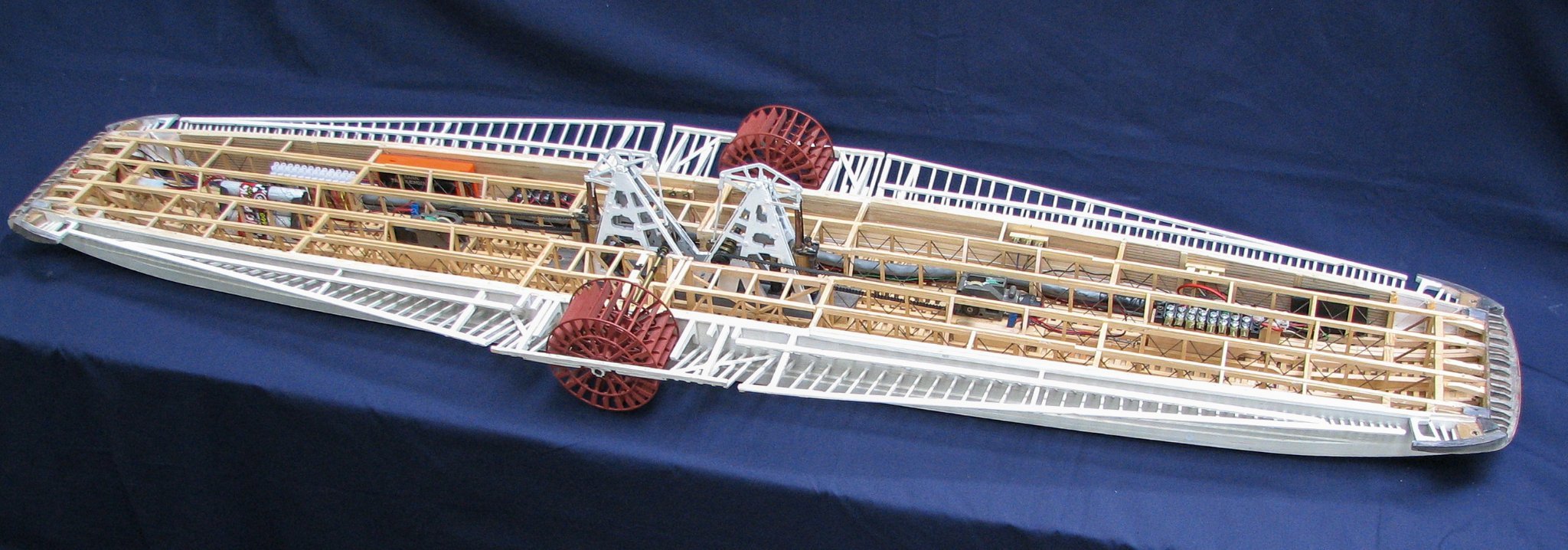
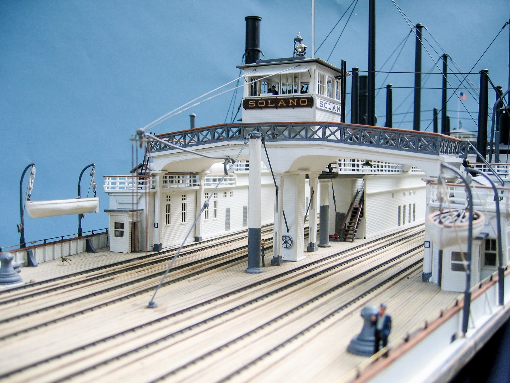
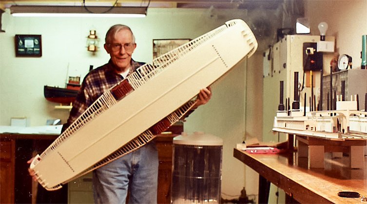
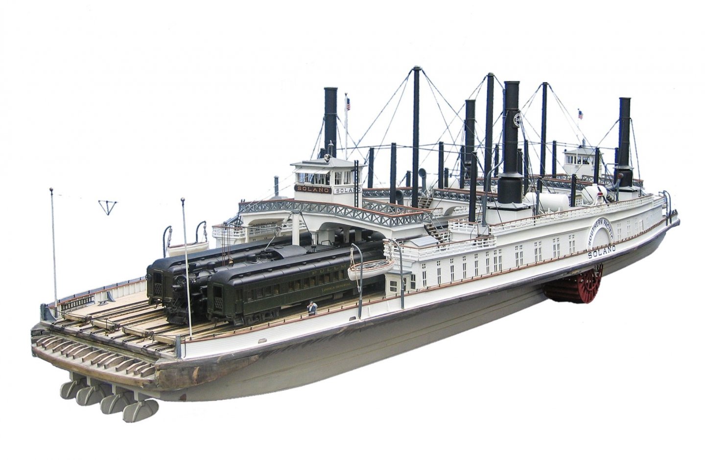
Welcome to MSW, Blair, from a fellow Coloradoan (Colorado Springs). I think I found the perfect intersection of model railroading and shipbuilding! Back in 2016, my thread on the brigantine Galilee attracted a comment from Thomas Rubarth, who resides in Omaha, Nebraska—also a model railroading fan. In collaboration with a ship modeler friend of his, Jim Turner, they built a huge model of the train ferry Solano, which operated between Benicia and Port Costa in California from 1879 to 1930. The model was built to HO scale and included HO rolling stock. Here are several photos Thomas shared with me during our correspondence: This is the model builder, Jim Turner holding the hull. Note the asymmetrical positioning of the paddle wheels. MSW is a wonderful organization of knowledgeable, friendly, and helpful individuals. I am sure you will find success in your endeavors here. Enjoy! Terry


- 20 replies
-
- 10
-

-
-
Roger, the CO of my first submarine described the nuclear propulsion plant as "just a sophisticated way of boiling water." 🙄