HOLIDAY DONATION DRIVE - SUPPORT MSW - DO YOUR PART TO KEEP THIS GREAT FORUM GOING! (Only 20 donations so far - C'mon guys!)
×


Gaetan Bordeleau
-
Posts
1,307 -
Joined
-
Last visited
Content Type
Profiles
Forums
Gallery
Events
Everything posted by Gaetan Bordeleau
-
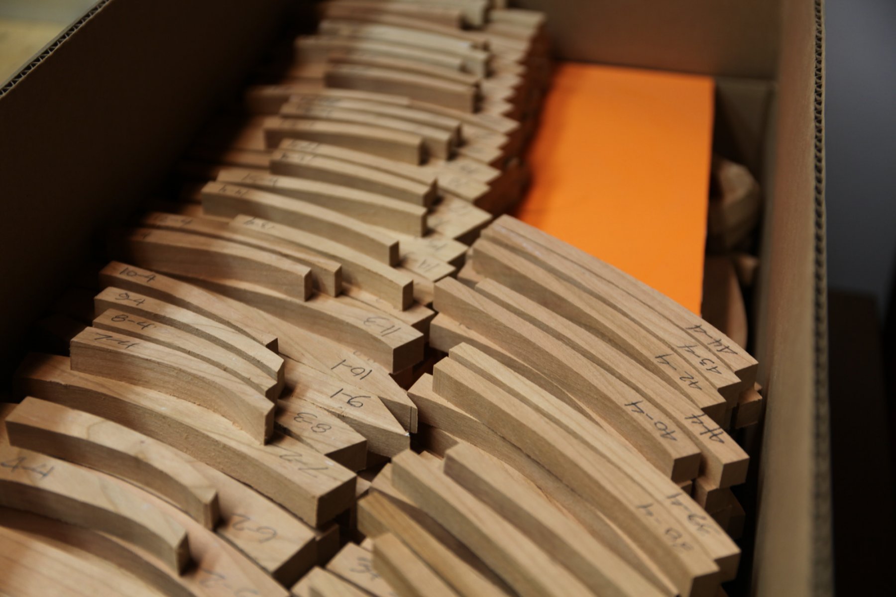
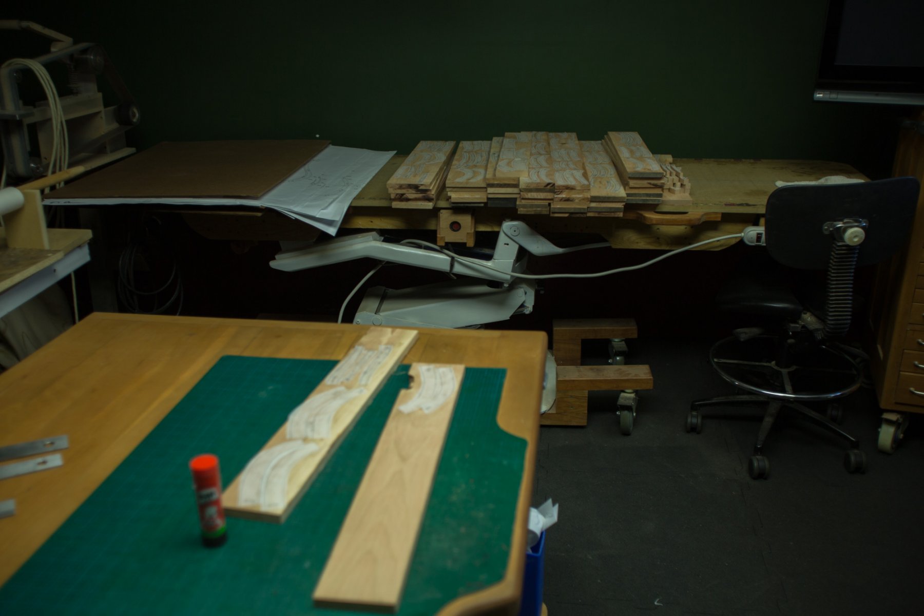
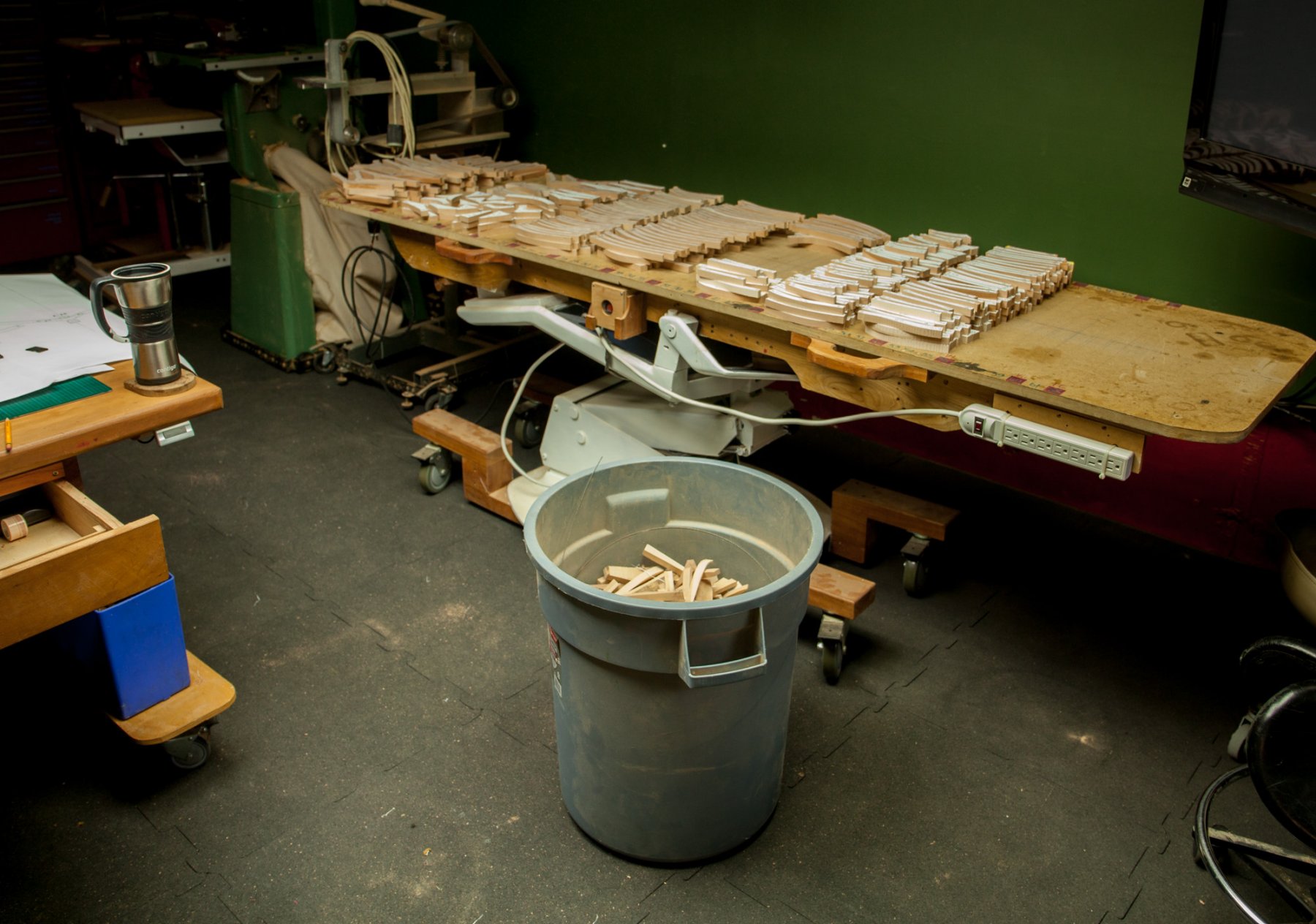
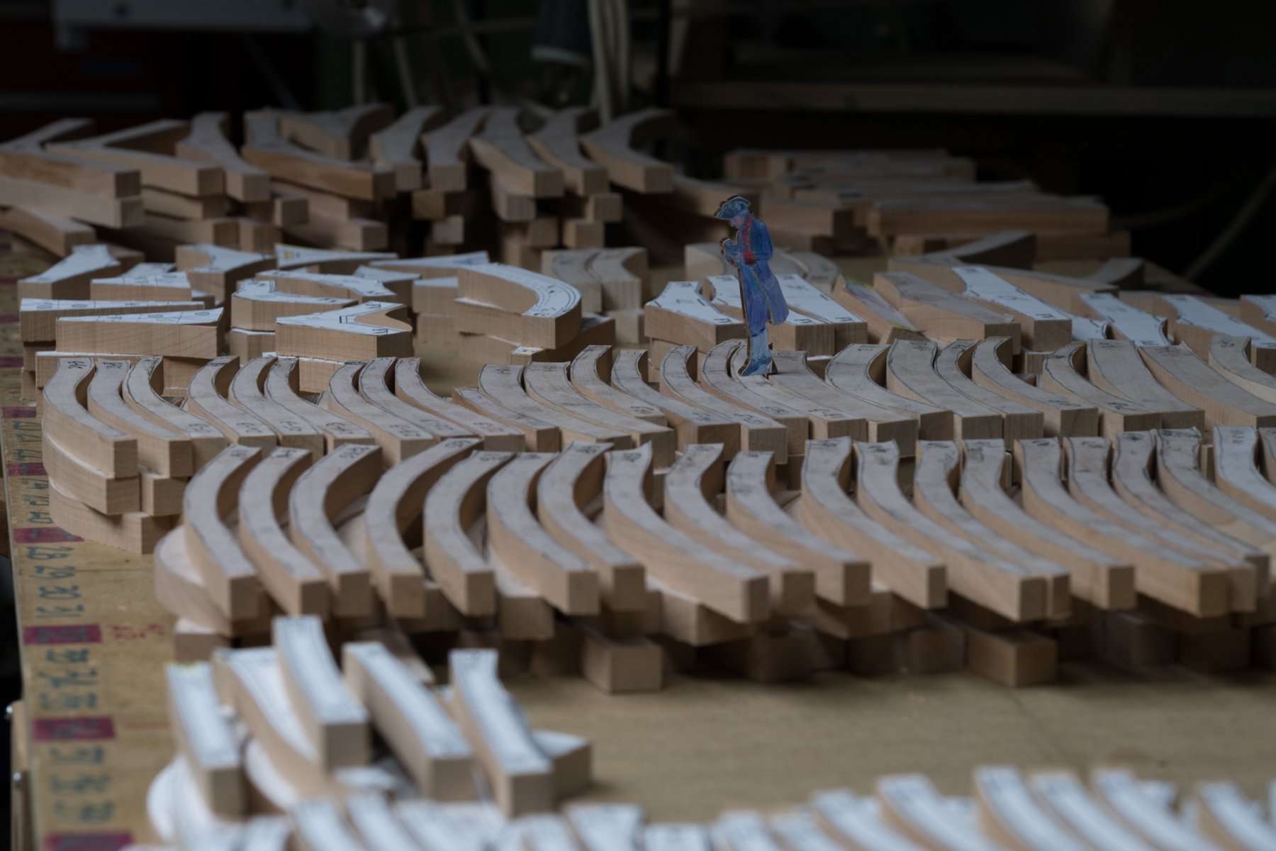
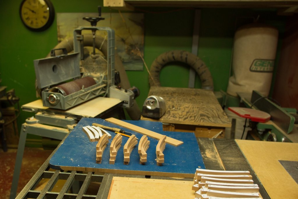
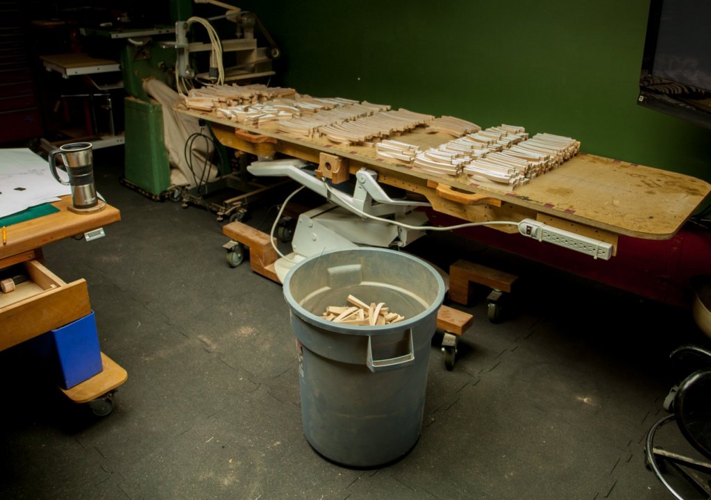
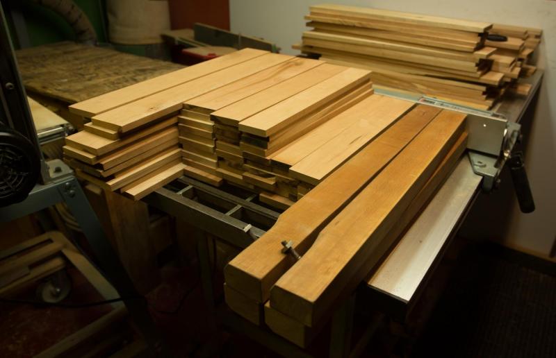
 Roughly, 62 frames are made of 1000 parts, each part has 4 sides to sand. The setup is as follow : inside curve, ends, outside curves. Then the tracing paper is remove with a scraper. A faster method is to pass the parts in the sanding drum, This machine is quite precise, much more than a planer because the adjustment can be made in 0,001 inch increment. Frames part are divided in 3 groups : left, center and right components. Left and right are put aside to keep the center parts which are going to be use to prepare the keel.
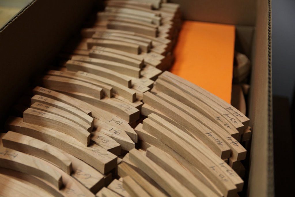


-
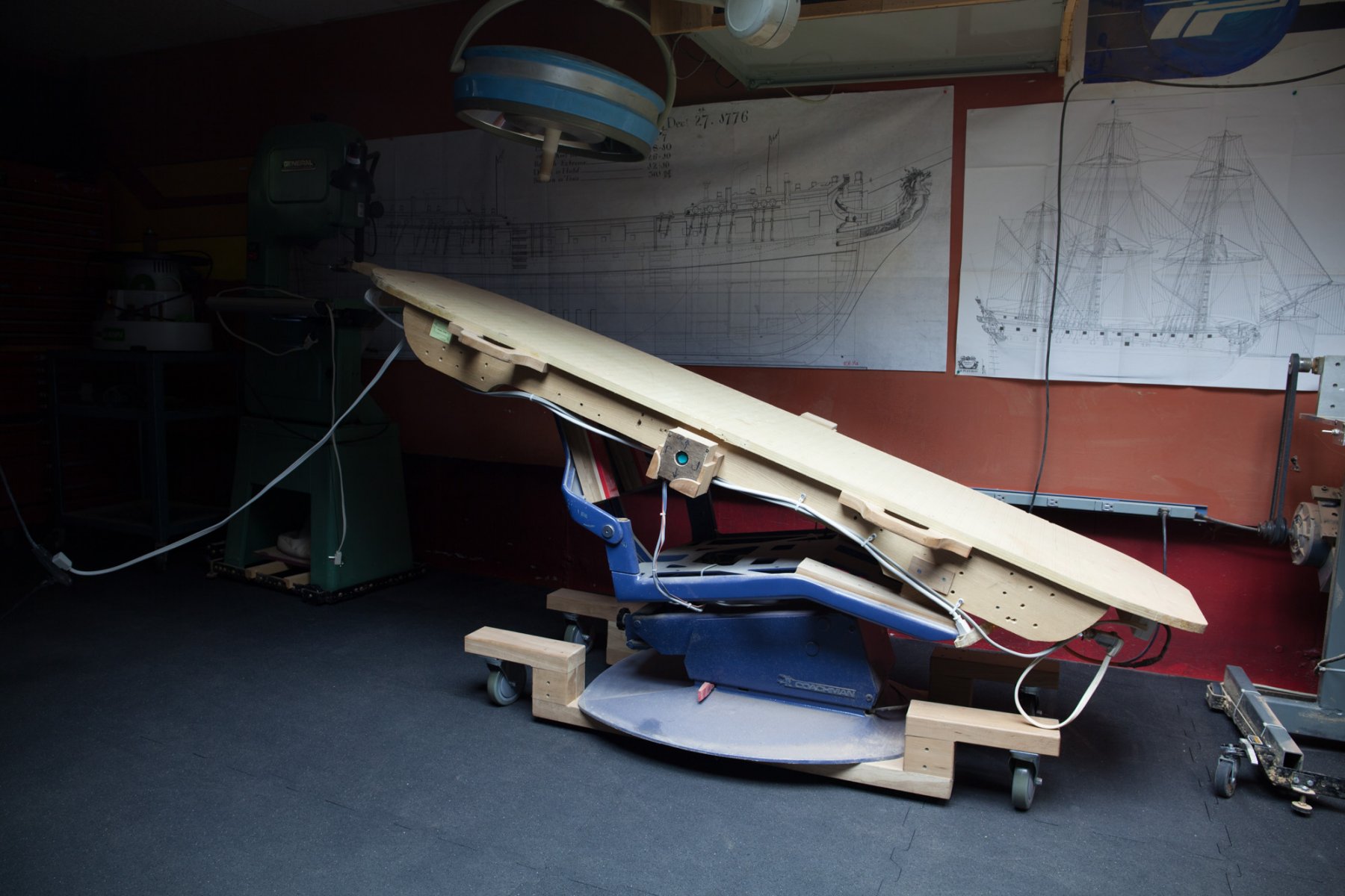
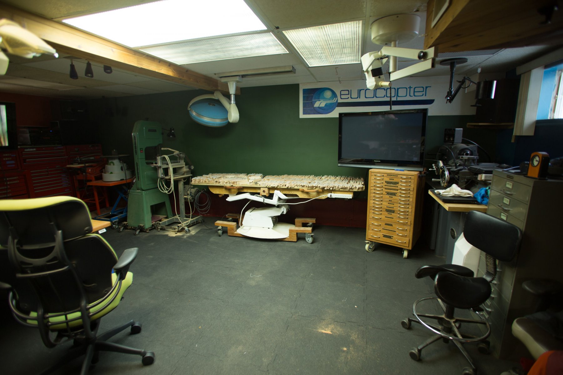
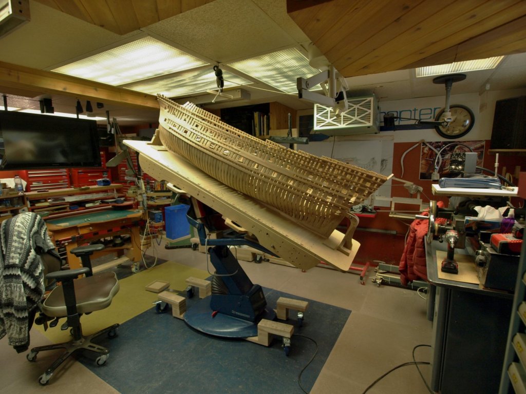
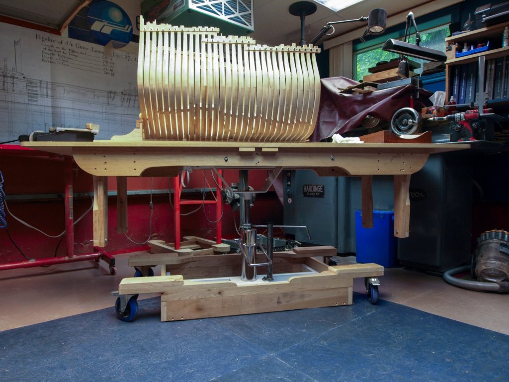
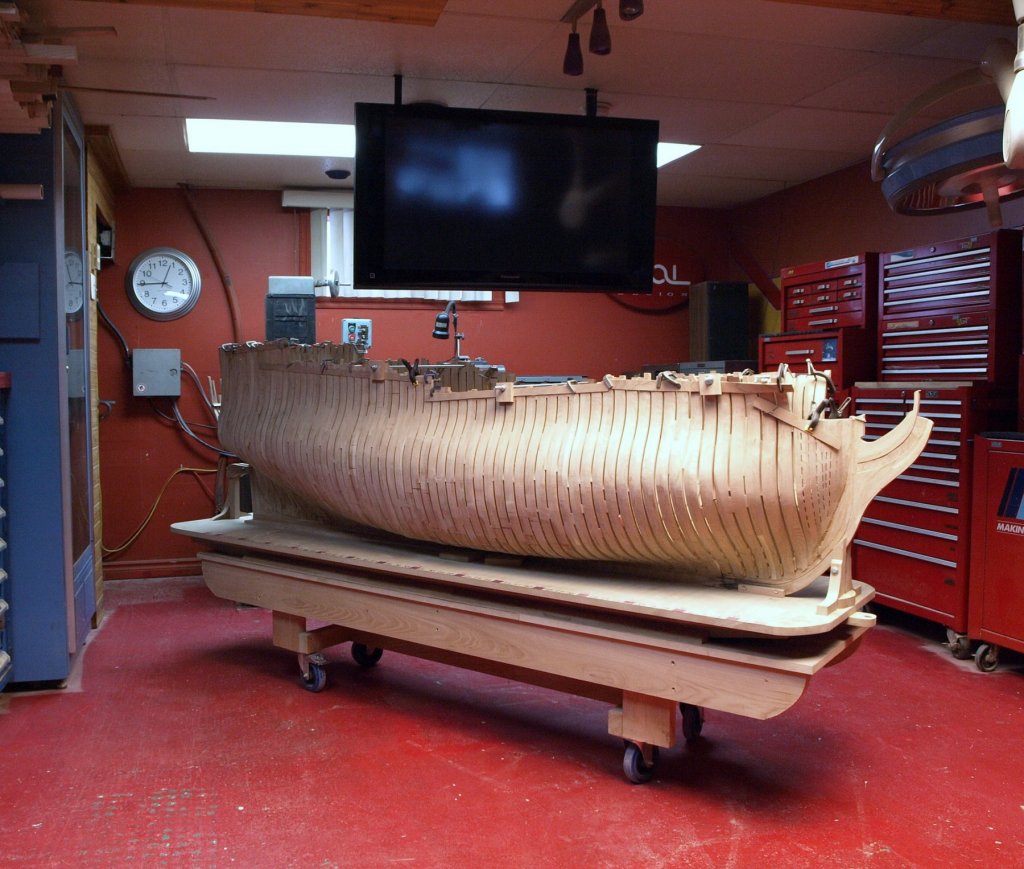
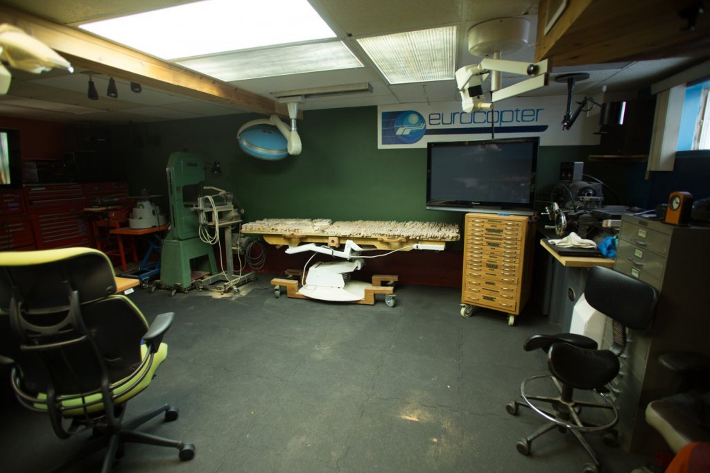
Druxey, you are right about rigging. In fact, the higher we have to work on an object the more useful come this table. Maurys, the chair came from the dentist but he did not gave the chair. Aviaamotor, you mist 1, there are 2. By adding angle to the support bench, we can keep the object very close to the ground. Denis, the size will be 8 feet long, exactly as in the last picture, which is also a 74 at 1/24. Even an adult could be put inside the model.
-
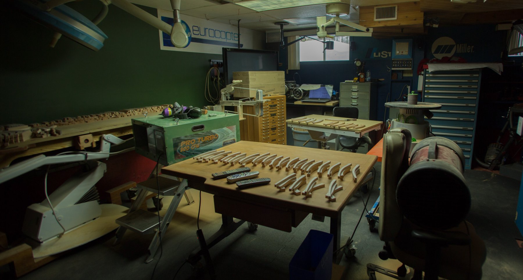
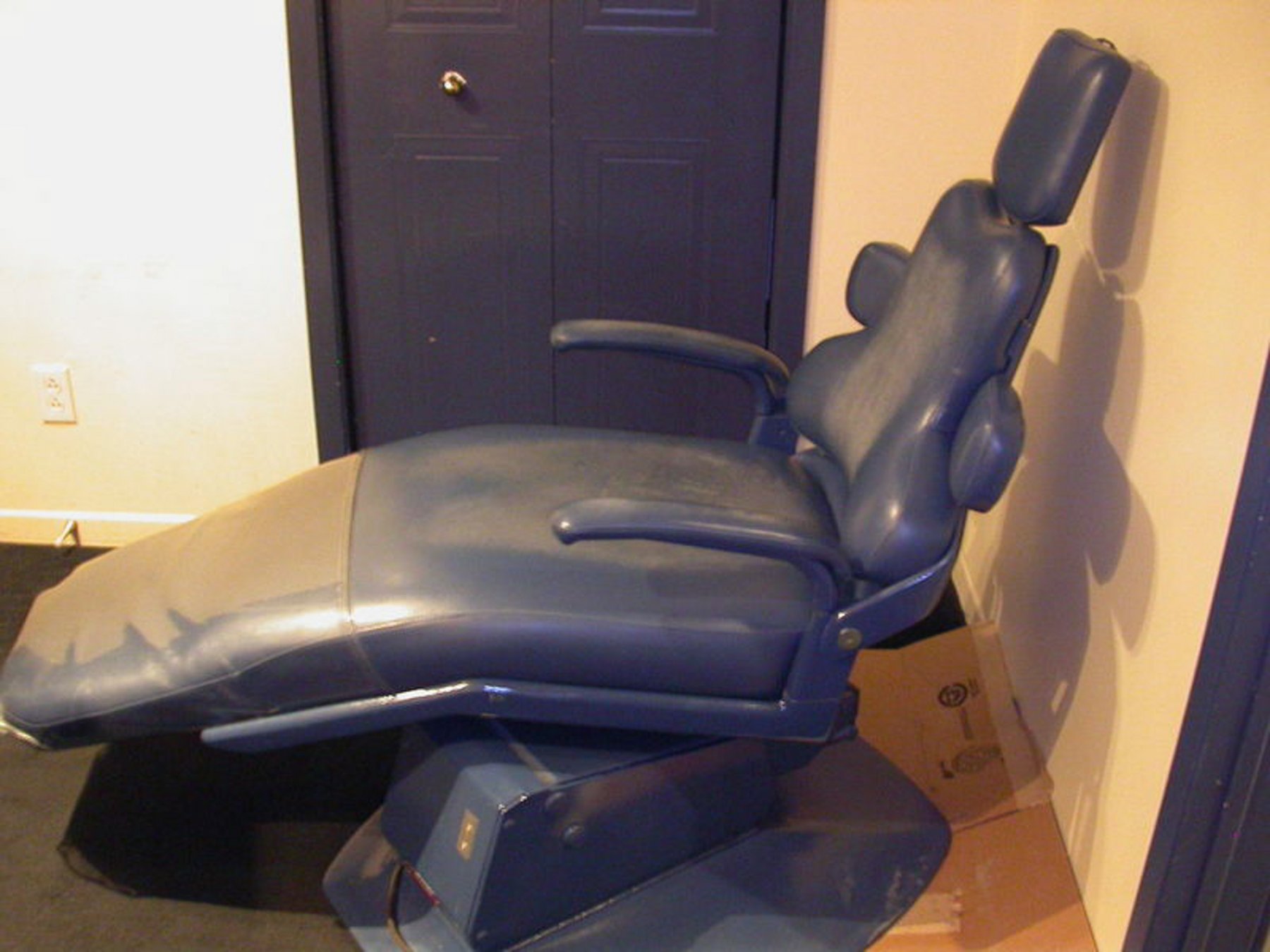
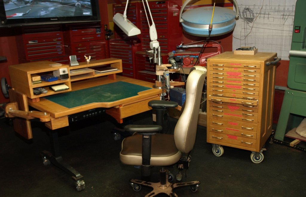
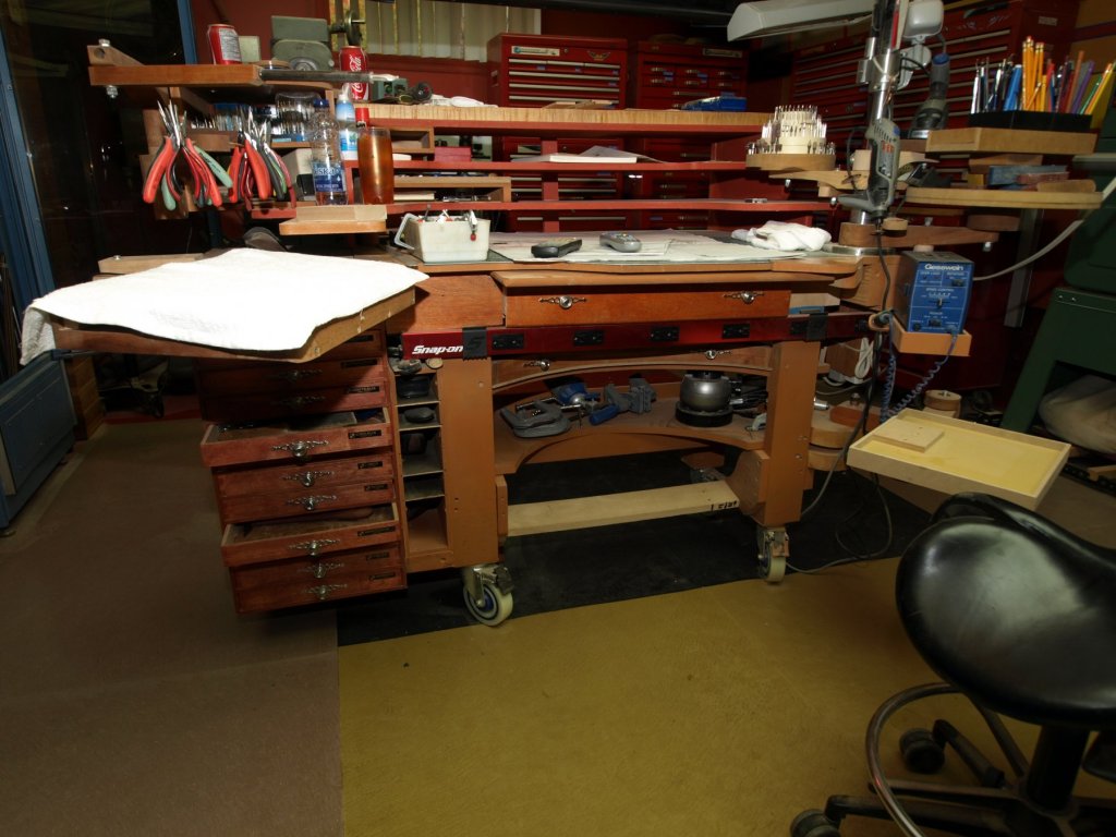
Thank you very much Pat, effectively, some process are very long to elaborate. I will explain an example in answering vossiewulf question. The first model at 1/24 was made on a low table which was even lowered later. The main disadvantage of a table is a fixed height. I wanted to find a better solution. Next step was a beauty chair with an oil cylinder. That was an improvement with a limited height adjustment but the horizontal stability was not great. Legs were added to help. But still I was not satisfied. There had to be a better way. Jewelers work on height adjustable table. This photo allowed me to enter in a new world to help to work ‘’in the better position’’. Working on the model at the wrong height is much more tired. I had to find a better height adjustable table. I thought to a electric dentist chair. If the back is expanded horizontally, you have a good base to install a table. There are 2 adjustments on the table height and angle 0 to 45 degrees. On internet, in Quebec we have Kijiji who sell all kinds of used things. There I found a used dentist chair for about $500. I am very satisfy with this new table. The only modification I did I changed the color blue to white, I prefer the look. Then this chair brought me to the next step by making me to understand that working at the good height makes a lot of difference and it is a lot easier to work and you can work for a longer period of time. When I began the first model at 1/24, I did a small table to be use a work bench charged with tools. It became very heavy so tools were separated from the table. All the small tools for model ship modeling were regrouped in a same place, a chest with lower drawers to lose as less space as possible. Then, only one thing was missing, a height adjustable workbench. I found a mechanism on Internet for an height adjustable table it can lift 300 pounds, around 150 kilos. I made a top for it. All these big tools often needs to be moved at the good place to work. If I have to go 100 times to the sanding belt, I do not want to have to walk 10 feet every time, I want to have the tool close to me. The easy way to do it is to install wheels and then you can work more efficiently. Our friend Mike, found at IKEA, a very affordable height adjustable tables : 2 or 3 positions, adjustable with a hand crank or electric. Knowing what I know today, this is not the last tool I would buy, it would be the first one.


-
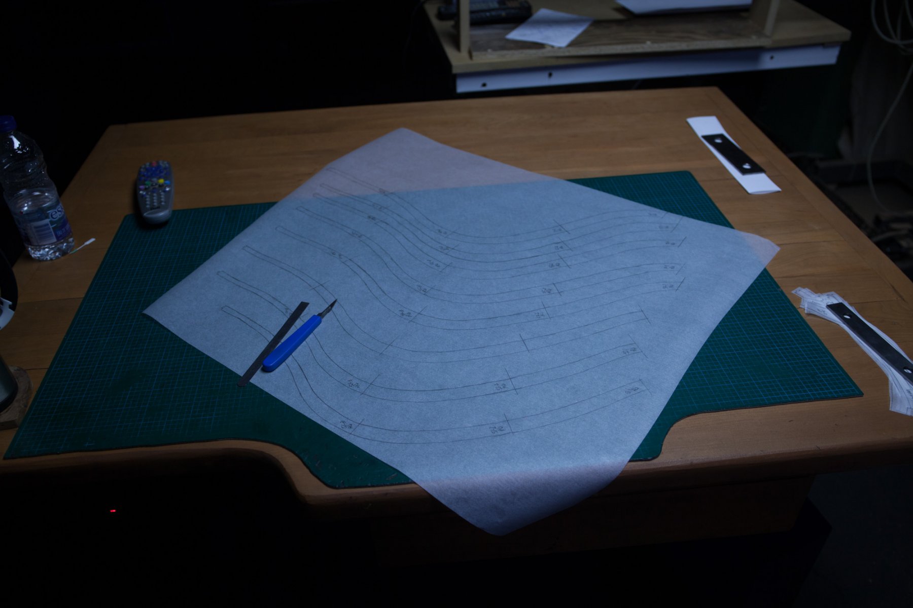
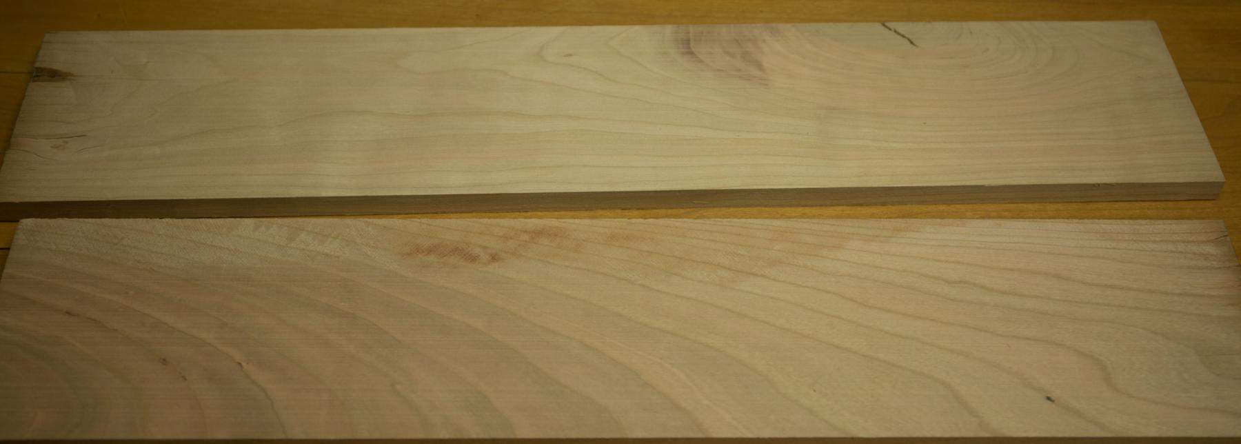
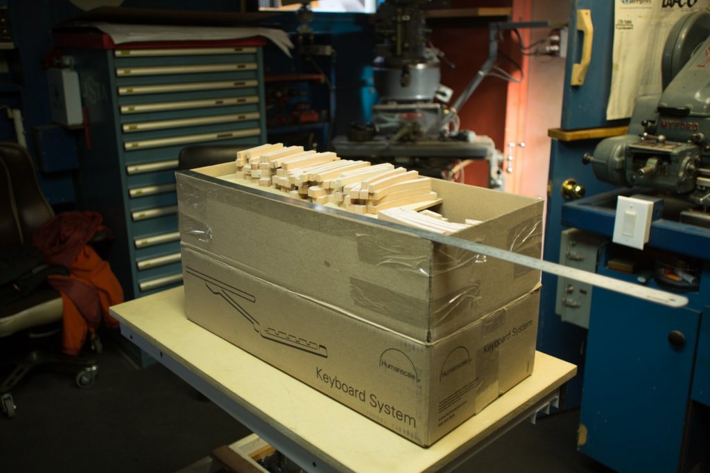
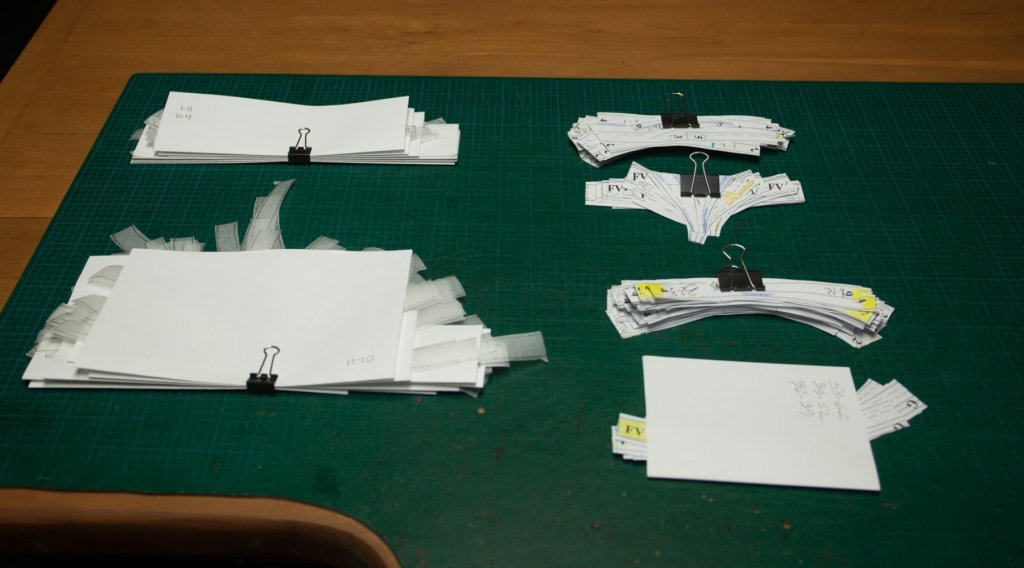
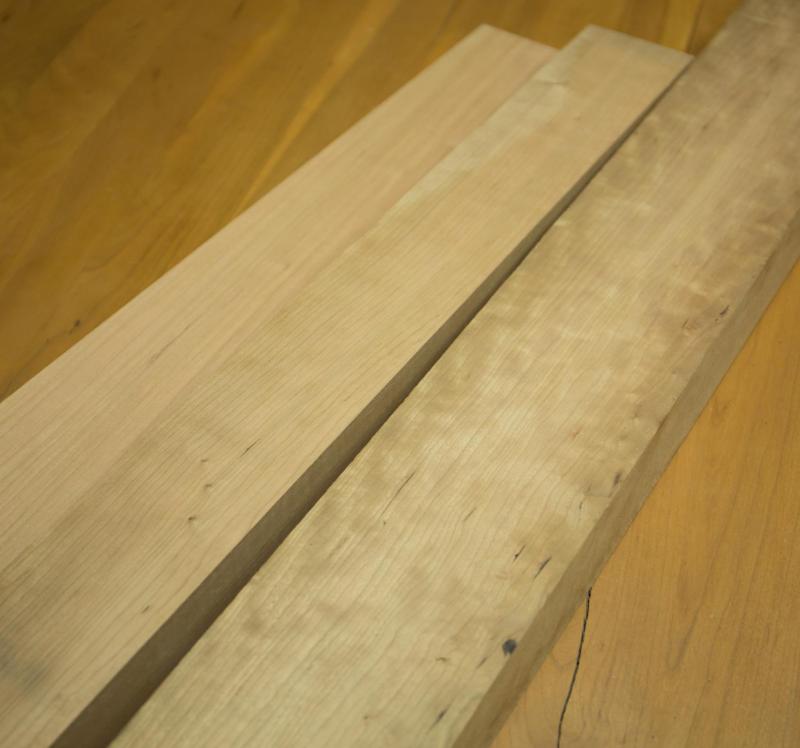
The box for the frames kit is ready to be shipped. I needed 5 copies of the frames. Frames are drawn ½, Frames 28 to 31 and 37 are not drawn, they are identical to other frames. I need both sides, each frame is doubled front and rear, plus 1 copy for later assembly. I drawn 3 copies and I had 2 photocopies. Next step to sand flush the parts and after prepare the keel and begin the assembly. The picture with 2 planks is the additional wood quantity I had to add, I failed in my guessing for the preparation of the wood quantity. In fact I guessed it by eye, because it is too much difficult to calculate, and to try to guess it is much faster.


-
What are the scales used to build models? Let's try some speculation. For the french I saw 2 scales: 1/24 used to teach the construction of the ship or to teach rigging. Also Augustin PIC built one 74 at 1/24. Many models are built at 1/48. English ship models I know are built at 1/48 scale. We know that 1/48 was use, I would say, for 2 reasons: Build a model to present to the king for his acceptance for the construction of the real one at 1/1 scale. 1/48 scale represents the largest scale which ca be easily handle by one person. There are surely other models built at different scales in Museums. A standard scale would have a derivation from the english foot and would be a multiple of 12. It is also preferable to use one of these multiples because it will be easier to work with especially in ratio used like for reproduction: 150%, 200%, 300%, and other variations. I would not want to use strange combination because this makes it more difficult to calculate bringing even fractions. Also, if I use a weird scale, it will be impossible to use the proportional divider: my common use being to work on 1/48 plans for ease to use ( a 4 feet long sheet) and double the lenghts at 1/24 with the proportional divider. Let's try to guess what happened when they came with kit. (I do not know when, is this something new like 1970? I have no idea). Purely for money reasons, they created smaller scales. Is there a standard size to build? My answer is no and this is a kind of false affirmation. In fact, the standard scale is the size that everyone is using for his own reason. So there is no good or bad answer.

-
Redshirt, It is probably a nice interrogation to ask ourselves what it is the limit in the scale we can reach. I did explore few scales and I am probably at the limit I can reach. I remember vaguely to have seen about 30 years ago, in Montreal, a model made to learn the rigging to the officers. The model was about 20 feet long. At what scale I do not remember.
-
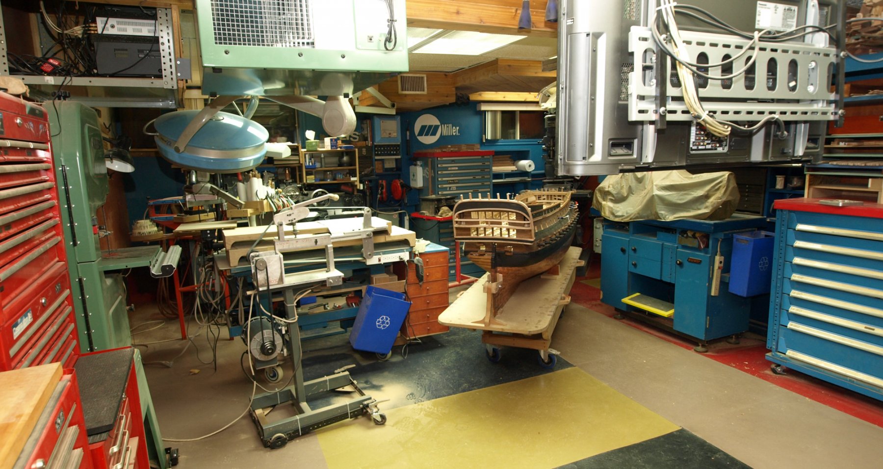
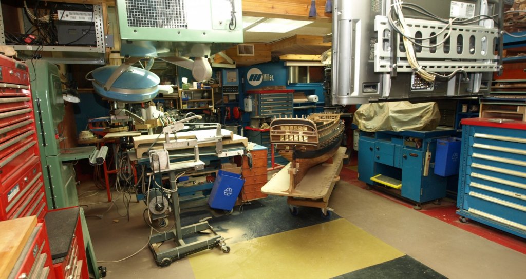
Hi Pierre, I was keeping a log but it was more for construction details, now it is just the build log on MSW. On MSW 1.0 we saw another 74 at 1/24 and weight was 130 pounds. It was difficult to move it upstair. The guys were strong men. Bigger door, bigger home, bigger workshop, bigger ship; it took years to be installed as now. There are a lot of wires and some heavy machinery. The most difficult to bring in was the Hardinge lathe, quite heavy. With that lathe, over 1 ton, I understood what turning without vibrations means. I am satisfied with the installation and it' s versatility. Having the medium tools on wheels is a big plus. Having the tool at the right place at the right time can save a lot of time and a lot of walking. There could be another possibility a 74 at 1/12 but made in 3,4, ,5, or 6 parts slices, may be I should ask Karl to come to help me.
-
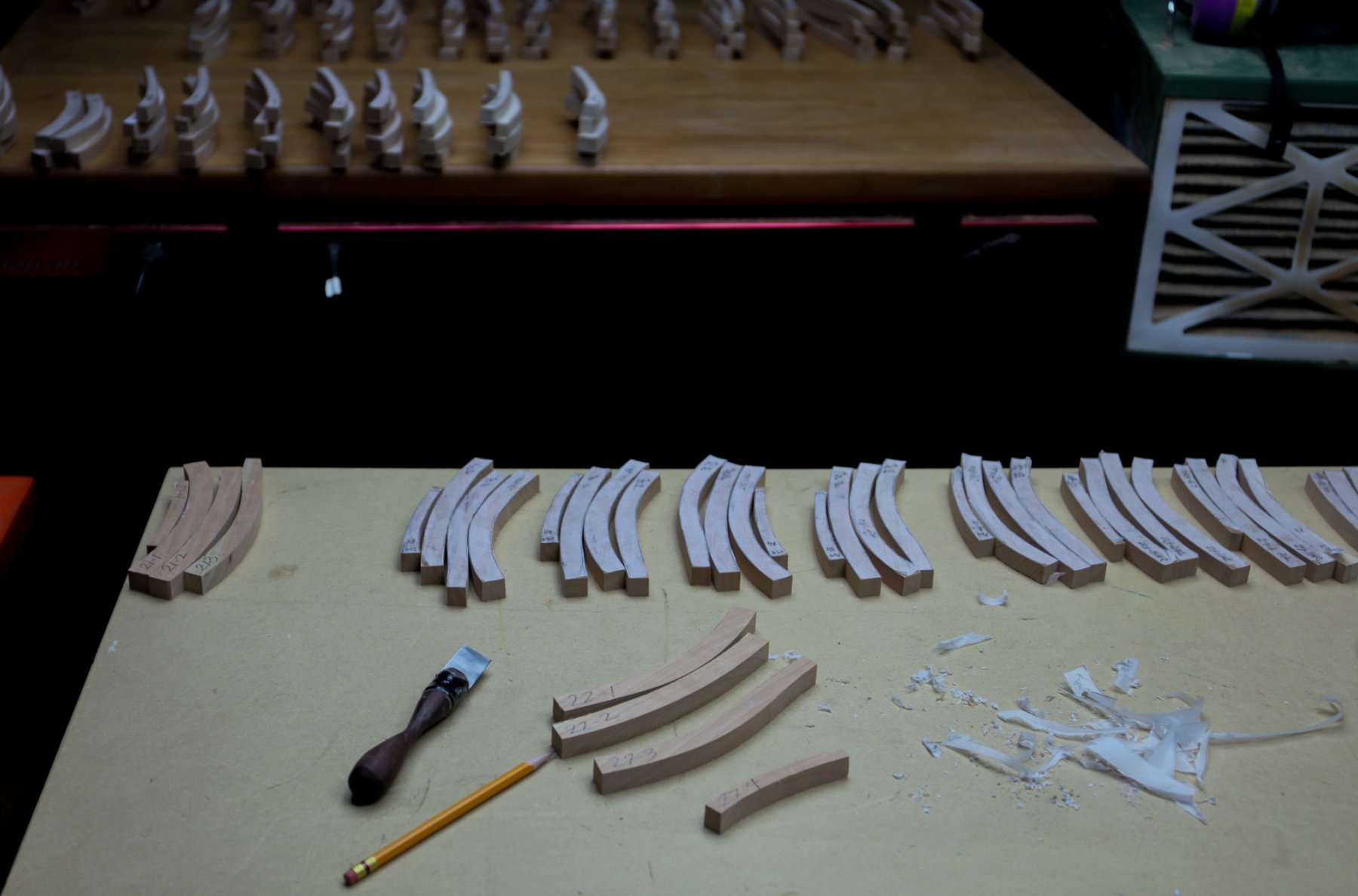
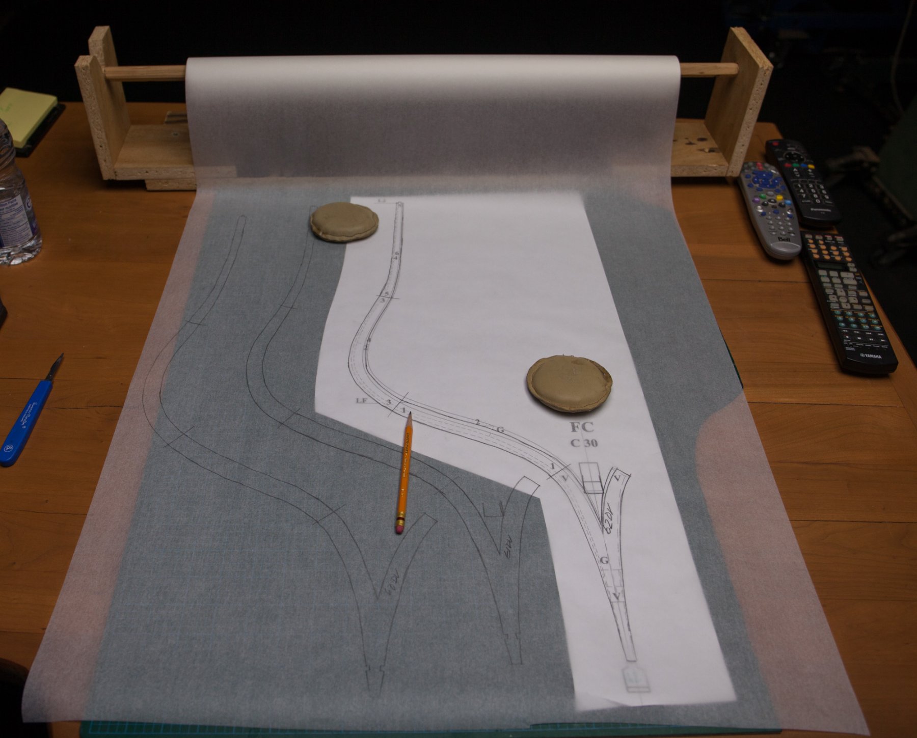
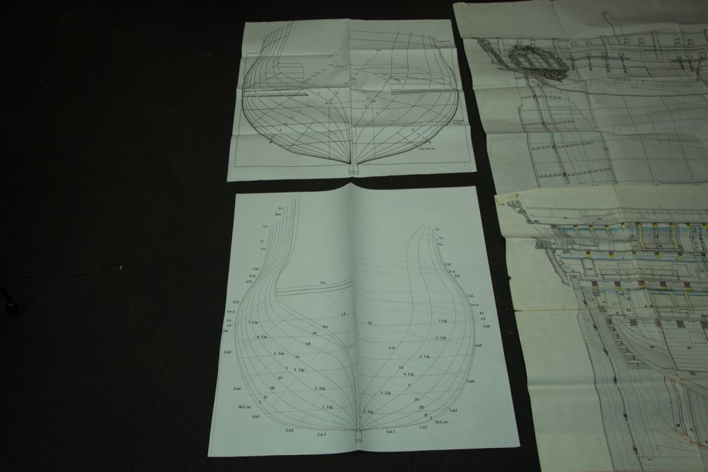
Preparation of the frames for the KIT. I have to draw the other half of the plans. Drawing is made by hand, it is easier to draw a circle than a straight line and all the frames are only curves About 2/3 of the blanks are cut, a lot of wood is use and a lot of wood is thrown in the garbage, up to now 1 ½ trash can.

-
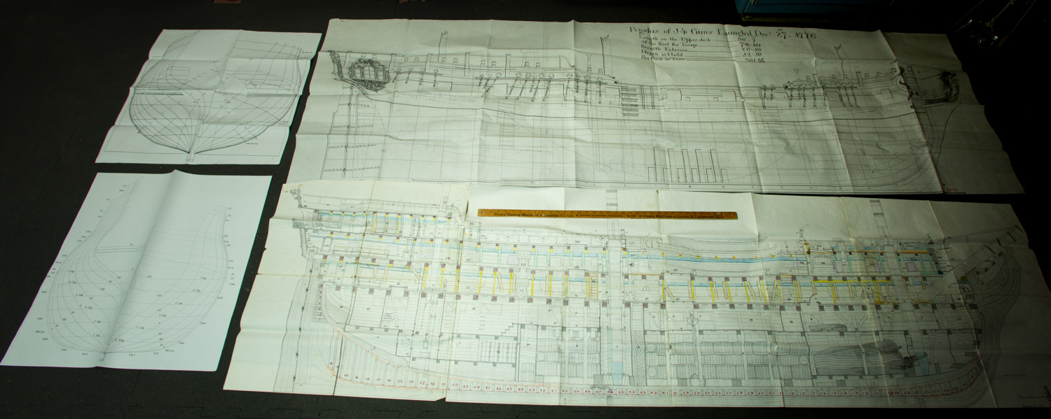
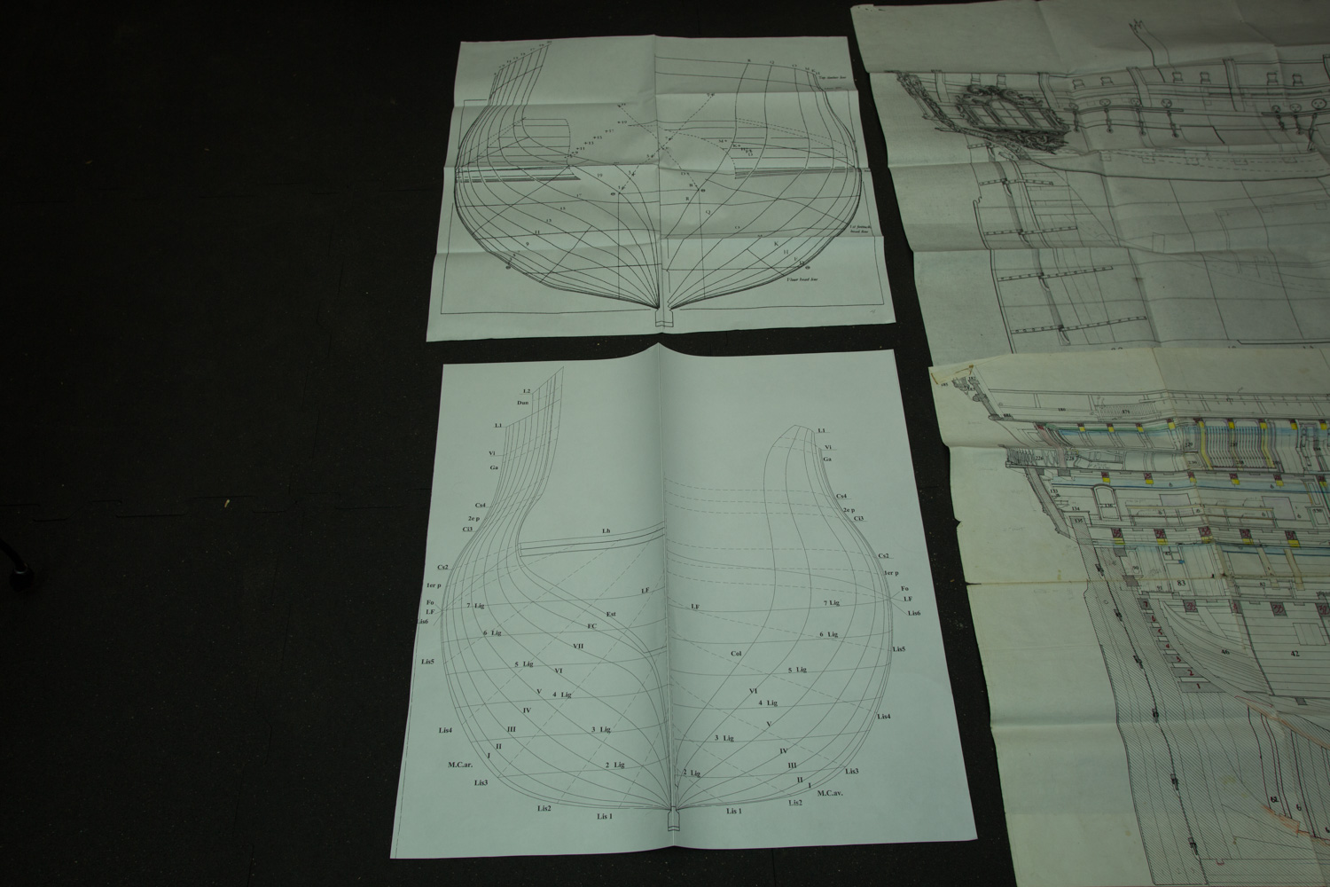
Hi Peter, What a nice offer and a nice project you have. I have no abilities with Autocad. Even If I bought plans from Lemineur I draw some frames parts. I saw pictures from 1949 of this ship. I am now using Lemineur drawings enlarged at 300%. There are many reasons if I still want to build a forth 74 according to Boudriot drawings. I like his artistic vision. 1775-1780 is a period, where the shape of the 74 was very nice. To use your plans the measures should be identical to Boudriot' 74. I do not know enough about this ship. I also saw other models photos by Lemineur. For me, to be able to build a model, it is in part a love story between me and the model. If there is no attraction, there is no interest to build it. I will go with Minerve, a nice figurehead and stern decorations came to be simplified in comparison of the other extremity like Le Soleil royal. I could suggest some additions to the plans you are drawing. When you draw, you think like an architect and you do not want to repeat identical parts. For this reason, and to save few paper sheets, Lemineur has draw only 1 frame side. From the perspective of a model ship builder, it is not very helpfull. What I would like from a set of plans, is a complete set of frames. How many copies do you think I have to do if I want to be able to build a complete frame : left and right side, double thickness, each thickness having his own parts. I did 2 copies and I draw half side of the 62 frames. I am actually cutting the drawings in parts.
-
I will try to clarify what I mean: Bigger is easier in the way that it is easier to handle a part with your hand instead of only 2 fingers. Easier in the way that you have more control of your movement. The more control you will have, the greater the possibilities to produce a more accurate part. You can create smaller parts with great accuracy but you will need a greater concentration. At smaller scale you have to omit parts because many parts would be too small to handle properly. To understand more easily how a part is made it is easier to do it at a bigger scale and also you will understand better because you will see the components more easily. Probably I will understand better the intricacy of the construction if I do it at a bigger scale which will allow to see more parts.
-
Christian, the best advice I could give you go 1/32 (or 1/36). As we all know: bigger is better and we should not forget to add bigger is easier. Probably also 1 one of the brakes which can stop you is to say: I do not have room to store it. I did not have room to store one 1/24, and now I store two 1/24.
-
The limit is probably the width of the printer. There is also another limit, the size of the door. A 74 guns pass through the door but if we add masting, height become s a problem. The only way to overcome this problem being to have removable masts Does distortion for model-making purposes may become a factor in extremely large sizes. I faced that problem with my last build. Framing could have been a bit bigger, plus adding with other considerations such as humidity, the size of the ship move. In this way, I could not fit all the parts made exactly as ''plans'' are drawn, often parts must be adjusted. In this instance the construction of the model are the real lengths even if the guide are the plans. The bigger the scale the bigger the a compensation must be applied the length. The easiest to observe is the width which at 1/24 can easily change from 1/2 inch. In fact I guess that it is possible to plot drawings more precise than the real thing in wood. Metal would not be better, the length of a wire cable transporting electricity has a sag variation of many feet on a long distance PRECISION is important for many assembly, by example if we drill a hole smaller than the bar, problems will follow. In wood assembly, greater tolerances are acceptable. Different scales, different uses, different tolerances. I had the plan of HMS pegasus enlarged at 1/12 but the difference of the width of the frames was not that big. Frame size Pegasus 1/12 approximately the same size as a 74 guns at 1/24. Like this

-
Hi Sailor, this is a very good question, of course I will not, but I had plans enlarged from 1/72 to 1/24. giving sheets of 3 feet by 9 feet at around $15/ sheet Probably the maximum I could go would be restricted by paper size for frames, in this case 3 feet, printer larger than 3 feet probably exists? Size of the apartment is also a limitation. I like to move around the model and the model must move 360 degrees around, so physical limitation would be around 10 feet. At 10 feet May be I could do a frigate... may be next time
-
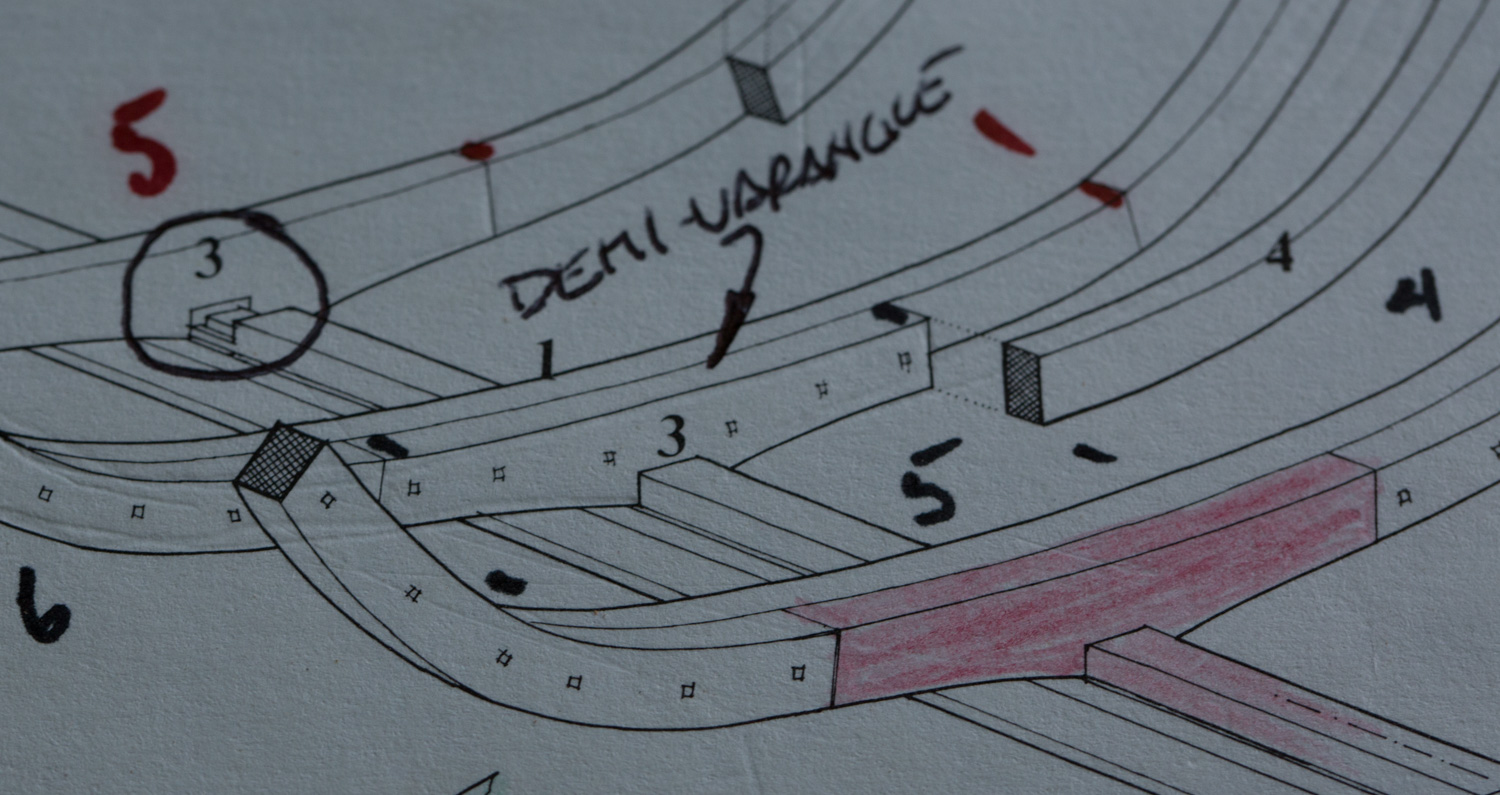
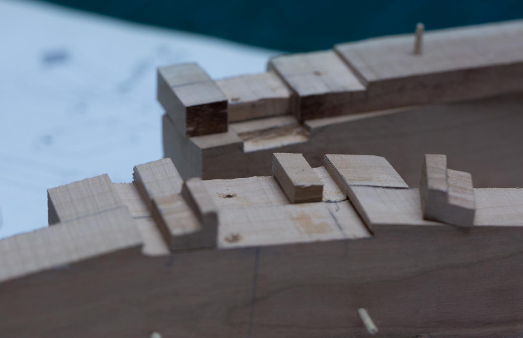
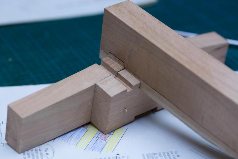
Very well drawn, I tried the assembly and everything interlocks together.
-
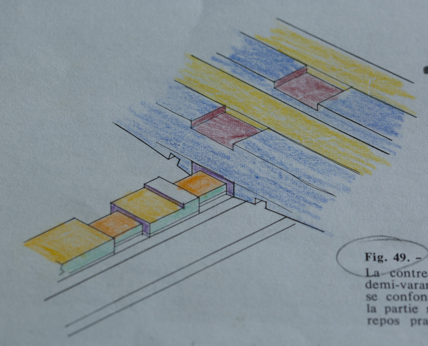
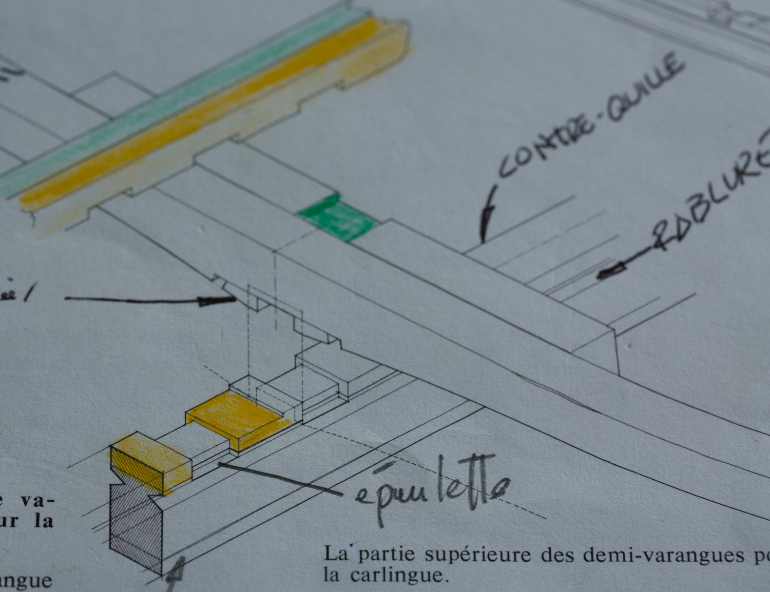
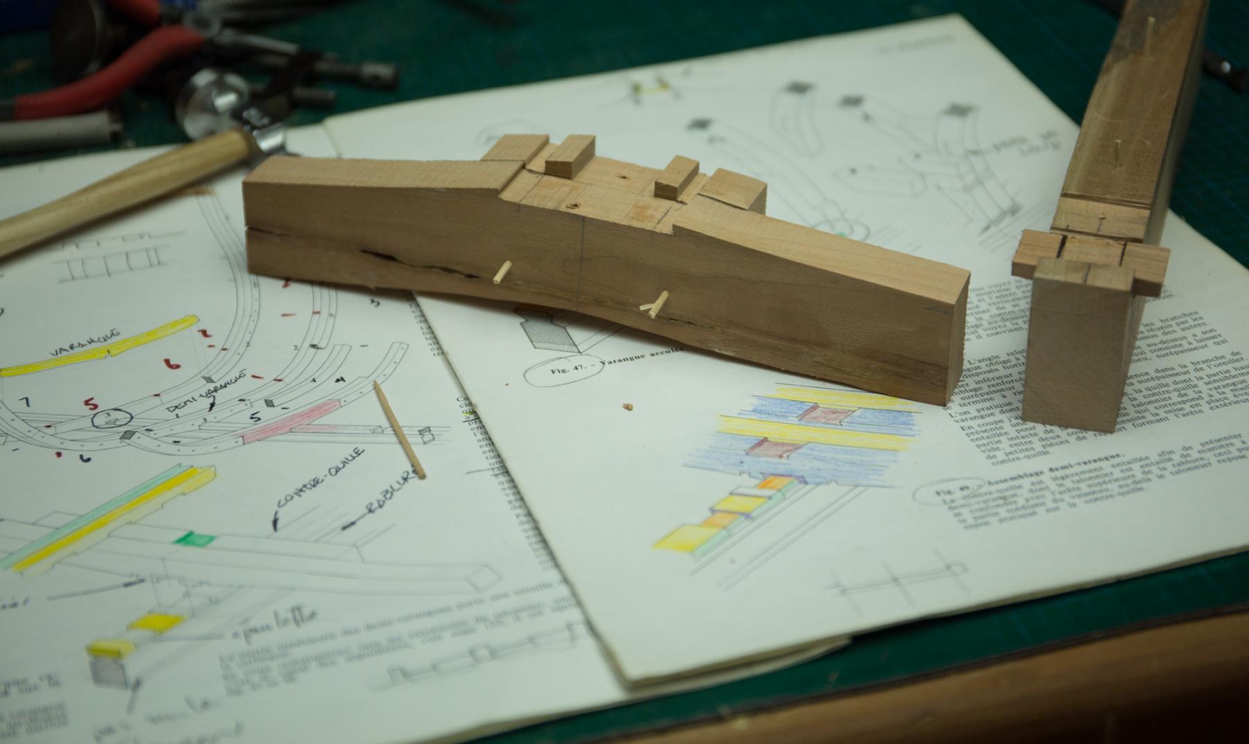
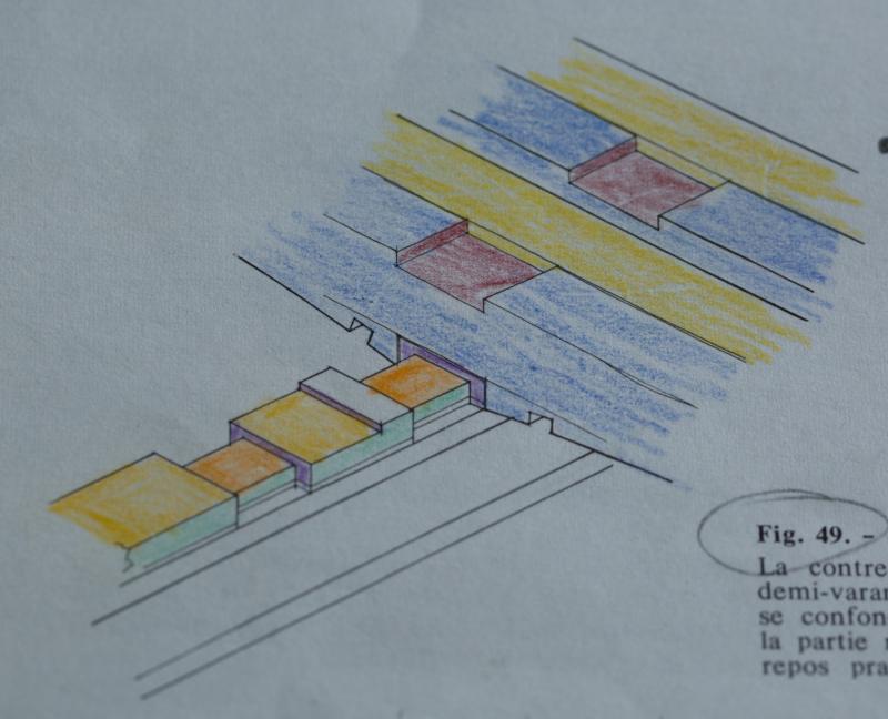
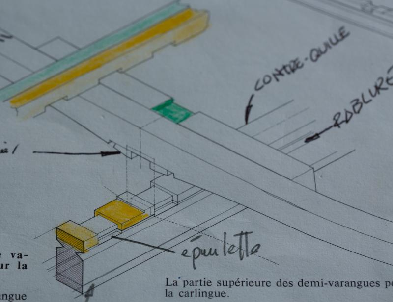
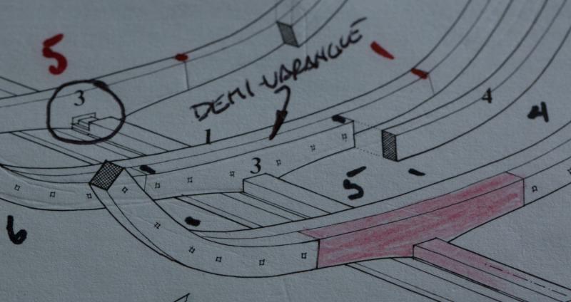
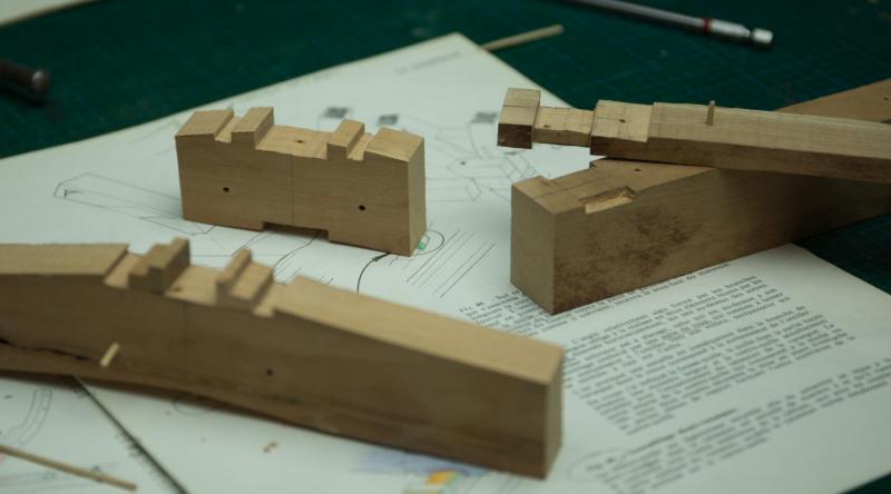
Tadheus, I am not saying my representation is good or wrong. I tried only to reproduce Boudriot’s drawing. 1 reason it is difficult to understand is because the drawings use a piece called talonnier which is in the same family as talon, heel in english. There is text explaining the talonnier but drawings show it partially. If you can provide better drawings to explain, please do so.
-
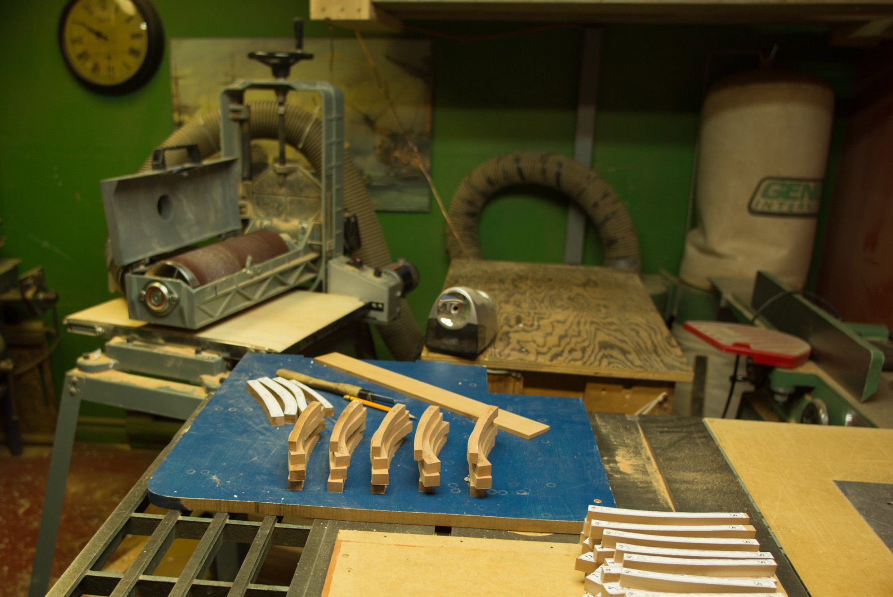
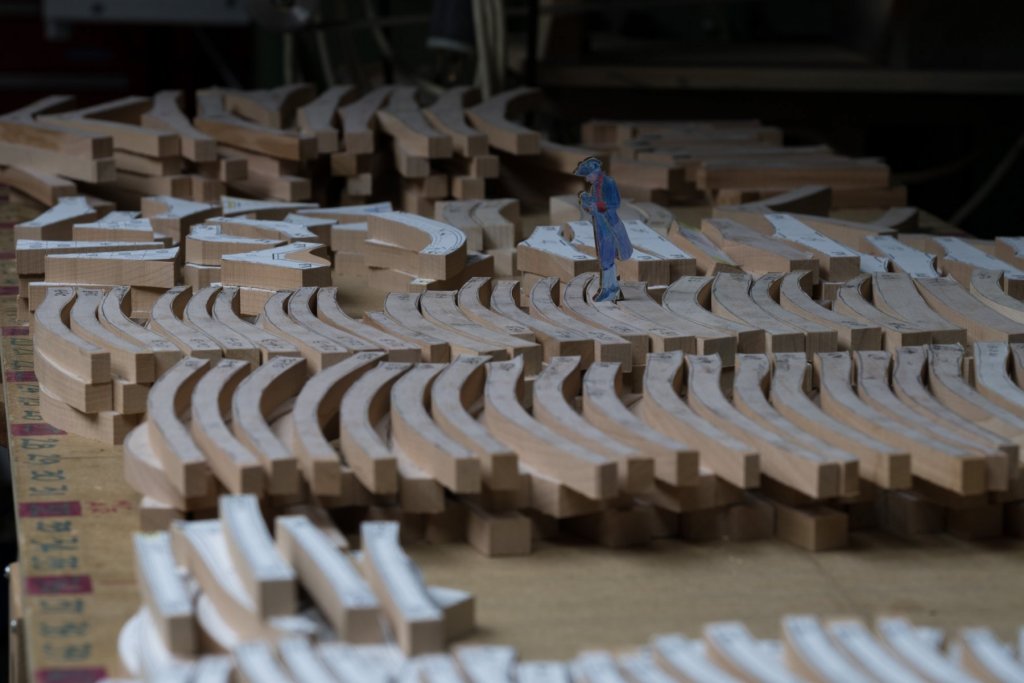
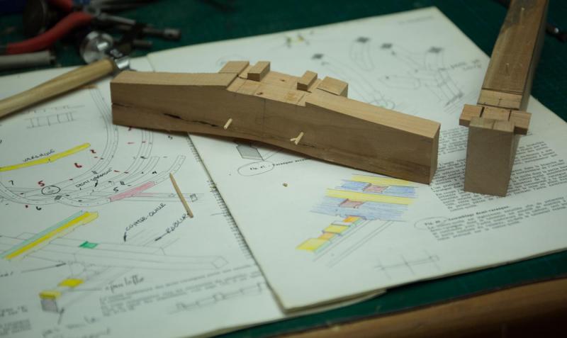
The smaller the scale, the less details is likely to be seen on a model ship. Here is an example: How the frames sit on the keel. Boudriot give an extensive description but How the heels fit under the frame is not so clear. It is difficult to see exactly how it is done. So I tried to manufacture 1 set of frames. You can see the result of this try.

-
Redshirt, the Fleuron, 7 feet is already stored, it was very easy. The first one, 8 feet was more difficult, it took me 2 years to find a place. In fact, when there is no place, you have to clear and build a place.
-
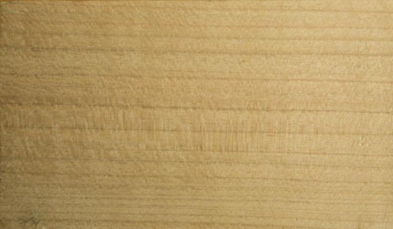
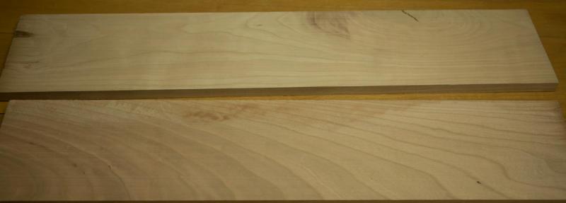
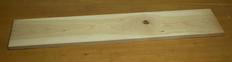
THE KEY TO USE CHERRY WOOD ‘’My mystery partner’’ will be starting a model of a 74 guns as soon he finishes his actual model. He wants to know if cherry wood could be a good wood choice for his next build? He asked to see a picture of the darkest wood avaialable. Why not show everybody the answer and at the same time, try to demistify if this wood could be use in a model ship construction perspective. For 3 different batches of cherry wood that I saw, the wood grain pattern was different each time. I have been working few years up to now and if I take time to regroup the observations I made during this period, I can observe 4 main wood grain pattern for this specific wood: 1- Sap wood is white and heartwood is somekind of different brown. Time darkens and embellish condiderably the color. 2- By comparison, which is often the best way to learn a subject, pear wood has no grain pattern. This gives the wood an adavantage for the model maker enthousiast. All the planks are identical for the wood grain. He does not need to select any plank, all the planks have the same identical grain pattern. From the point of view, workability pear wood and cherry wood are similar even if pear wood has a slightly higher density. Finally, for the sandability, both are identical. Cherry wood has a grain pattern. This pattern is different on the top and on the side of the plank. The pattern is partially governed by the annual year growth . Ideally if the rings were smaller, cherry wood could be the ideal wood to use for us, modeler. When you look at a plank from side or top the pattern can be completely different, This pattern comes back often and it is pretty nice to see but on 1 side only. 3- The worst grain pattern we can find is when when the growth lines come perpendiculary to the lenght of the plank. This kind is the less desirable to use. The worst mistake I could do is to use this pattern for the planking. Ideally by decreasing the scale of a model, we should also decrease the wood pattern of the grain. For the best results, we should find a wood grain which looks exactly like oak but at a much smaller scale. Does this perfect wood exist? I do not know. One of the nicest wood I have seen for the planking is apple wood, yet another fruit wood, our best friend. 4- Each wood as his own advantages. Oak has a grain pattern which goes in the same way as the plank goes. Occasionally, a cherry wood plank will have the grain perpendicular to the lenght of the plank. This is exactly this kind of situation which must be avoid. If someone succeeds to avoid this trap, it should be possible to get a good result simply by categorising the wood, not as a selling perspective classification as on the market, but as a perspective of use in model ship realisation. For the frame, the less attractive wood grain of the batch can be use and the best looking grain is kept for the planking.
-
The 74 guns was first published in 1973. This means there are only 6 years remaining to do an update for this 50th birthday of edition. Karl, The primary reason why I choose a model ship to build is always the same. I must find beauty in the model.
-
Hi Mauricio, Always nice to hear fro you Your vote won Congratulations
- 728 replies
-
- 1
-

-
- le fleuron
- 64 gun
- (and 1 more)
-
The main reason for his work, was to draw 11plates showing the frames. He also shows other possibilities for different 74. To work with set of plans containing errors is part of the game. Are these mistakes so disturbing that someone should not use these plans? If so, nobody would sell plans and nobody would buy plans.
-
For the "Fifth volume" it contains some strange details in the frames. And some examples are...
-
The width of the keel diminish at both extremity and it is well explained in the book. What I like about Boudiot is that he always explain at least at 1 place every detail. I agree that 3D CAD "build" -errors are easier to spot. You must admit that Boudriot was extremely talented to draw even in 3D. These publications are all you need for perfection is misrepresenting the truth, there is still a lot of drafting work to be done. I do not understand what you mean. Are the plans in the books sufficient to build a good representation? I have at least 20 different sets of pictures showing 74 guns built by as many peoples. Is there that much that drafting work to do if I want to build a 74? The only ones I did are the frames.
-
Ken, I do not know anybody who can write this kind of technical books and make 0 errors. It is part of the game. Please give us some examples? How many 74 did you build? Do you think that you cannot build the 74 guns because there are errors?
-
Hi Chris, I will answer you privatly Hi GemmaJF, 1/24= big and even bigger when you see it for the first time.