Ilhan Gokcay
-
Posts
636 -
Joined
-
Last visited
Content Type
Profiles
Forums
Gallery
Events
Everything posted by Ilhan Gokcay
-
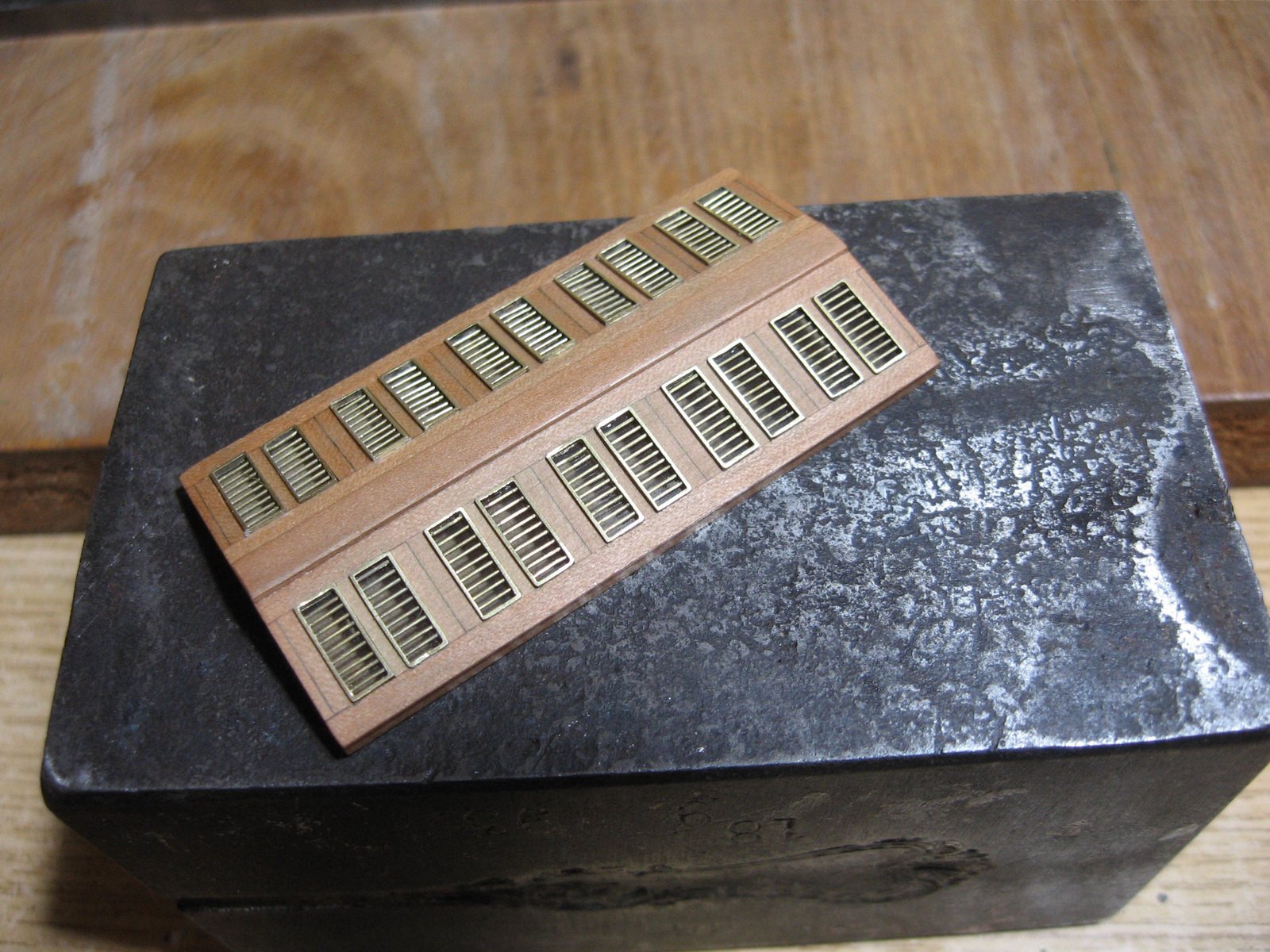
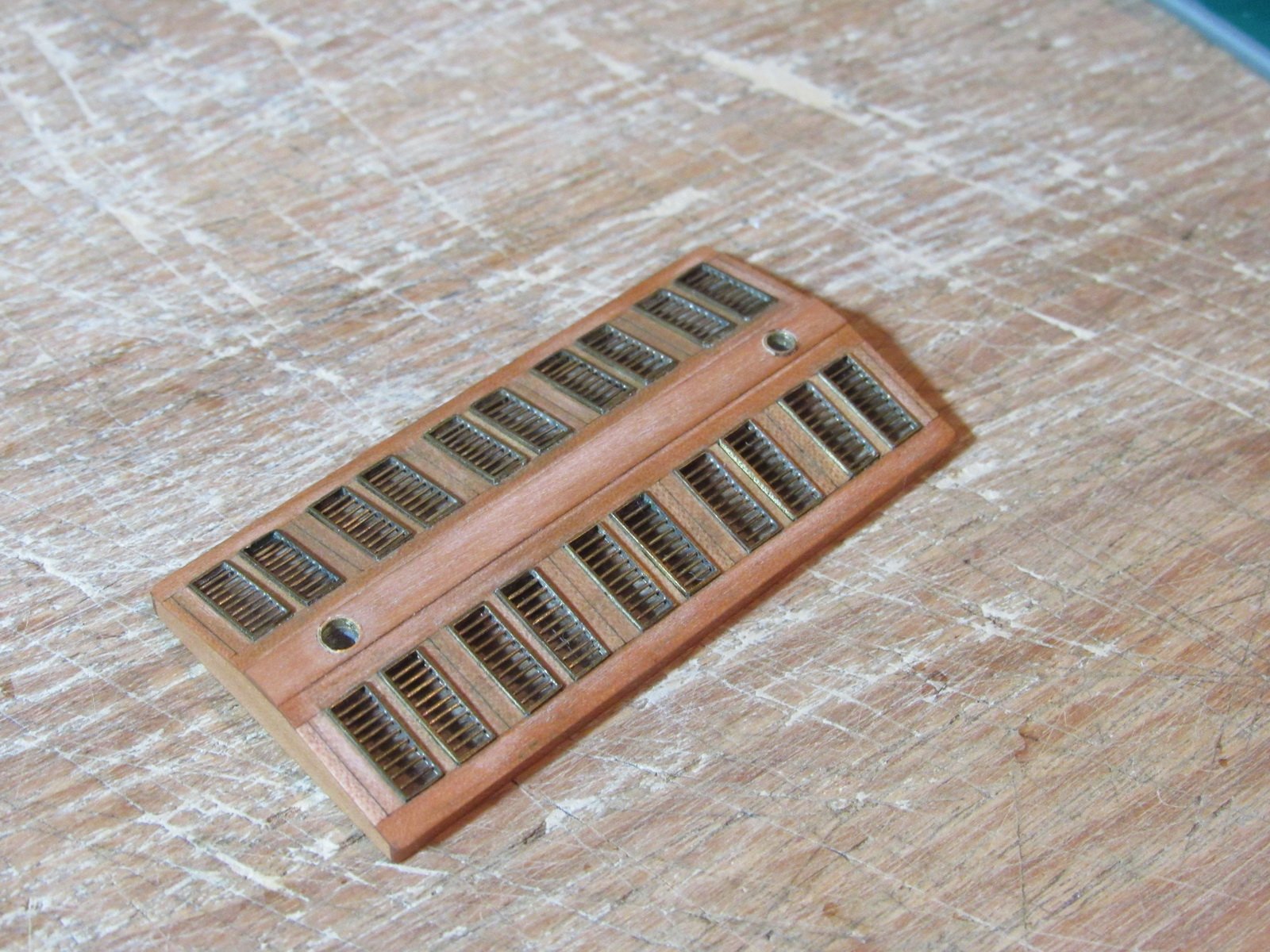
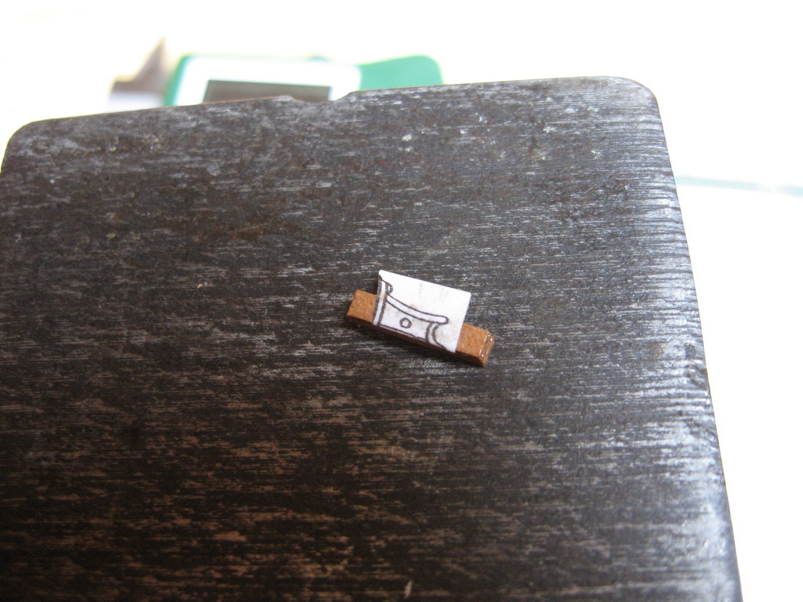
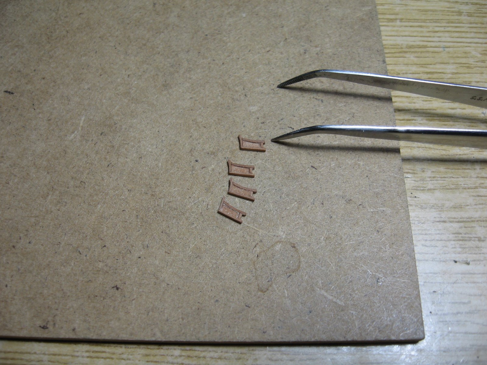
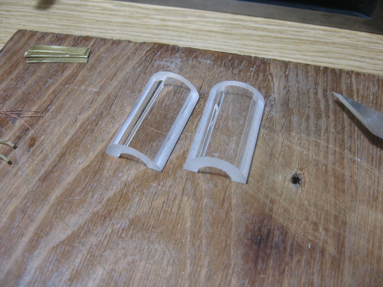
 Thanks Eberhard, 1/75 is a very difficult scale for this ship. If it was 1/100, PE would be ok, but not at 1/75. It would look like a bit simple. On the other side if it was 1/50 it would be much easier to make these parts. I did not realized this in the beginning. So I'am struggling as best as I can.
 -
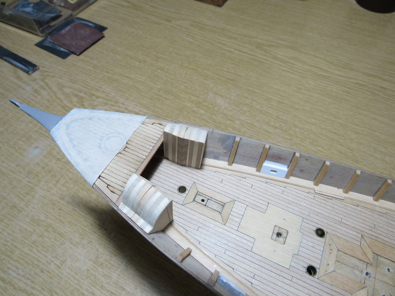
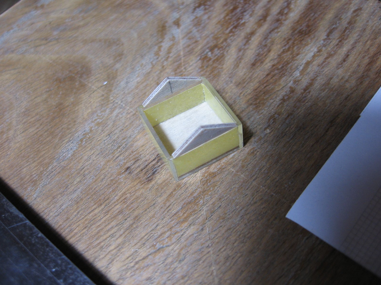
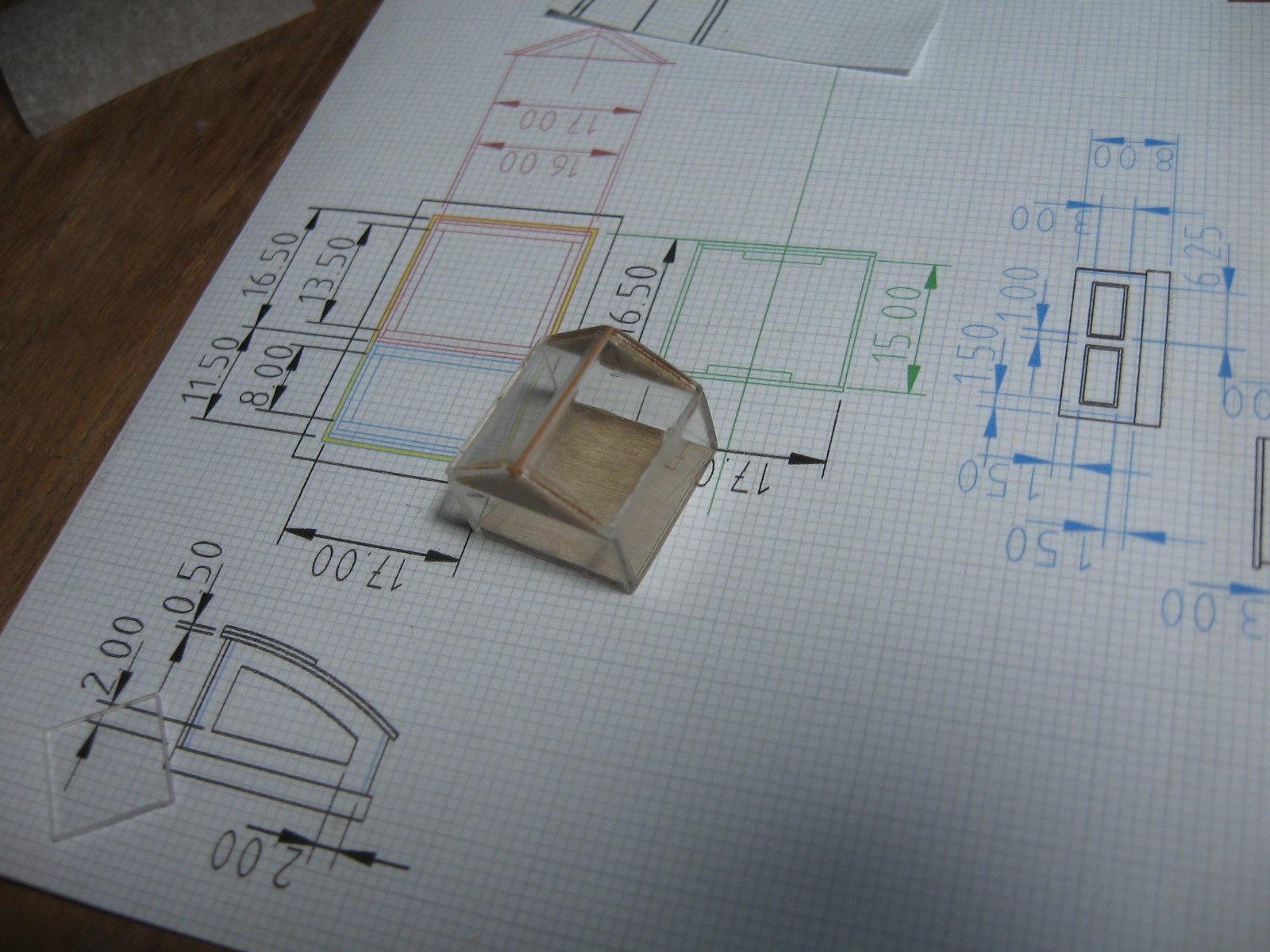
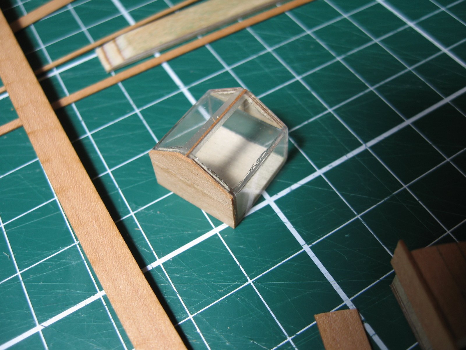
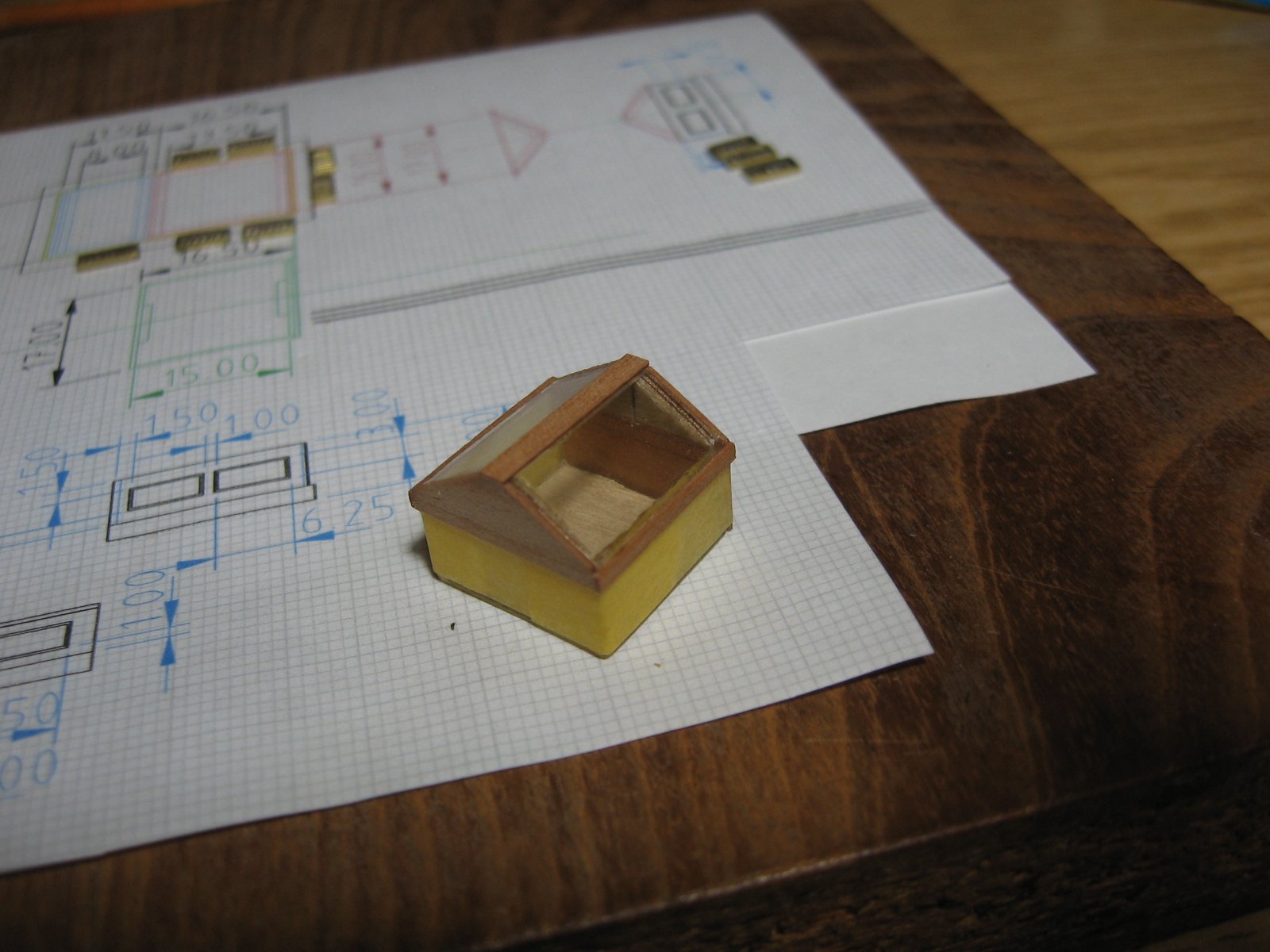
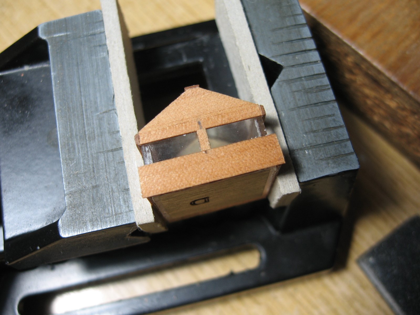
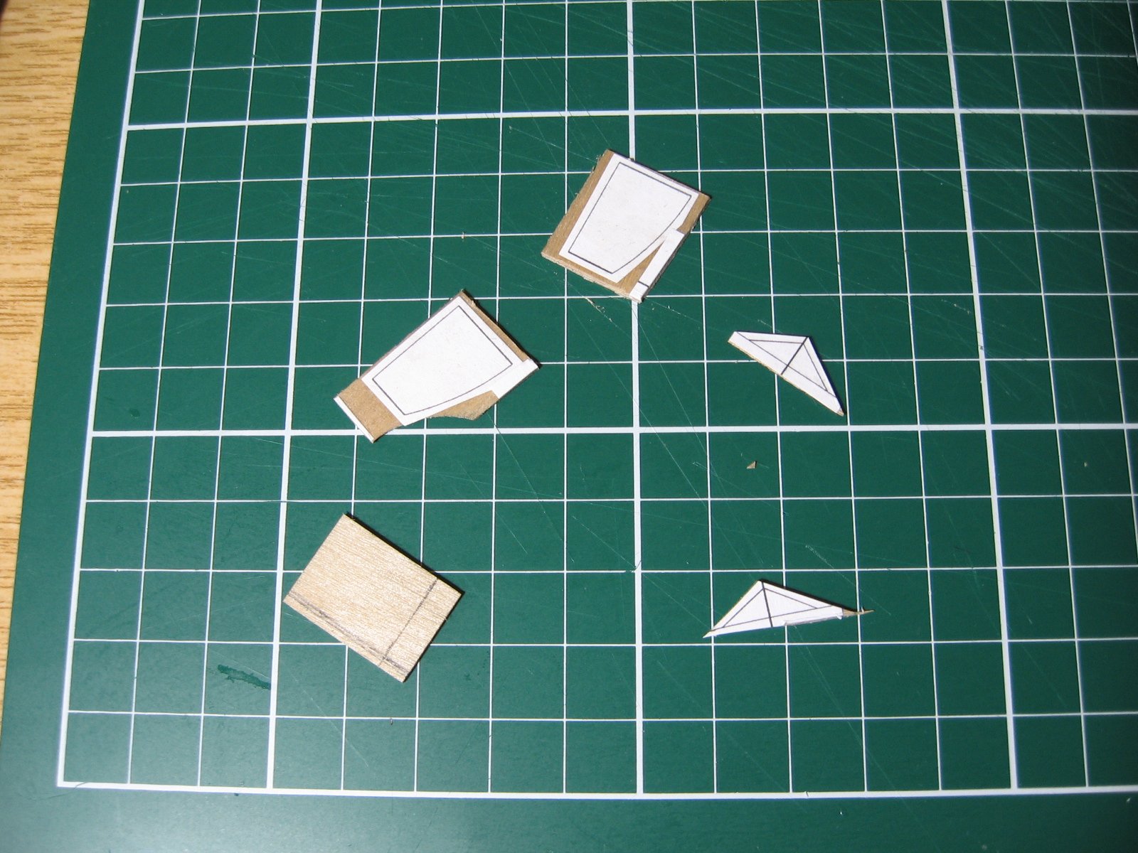
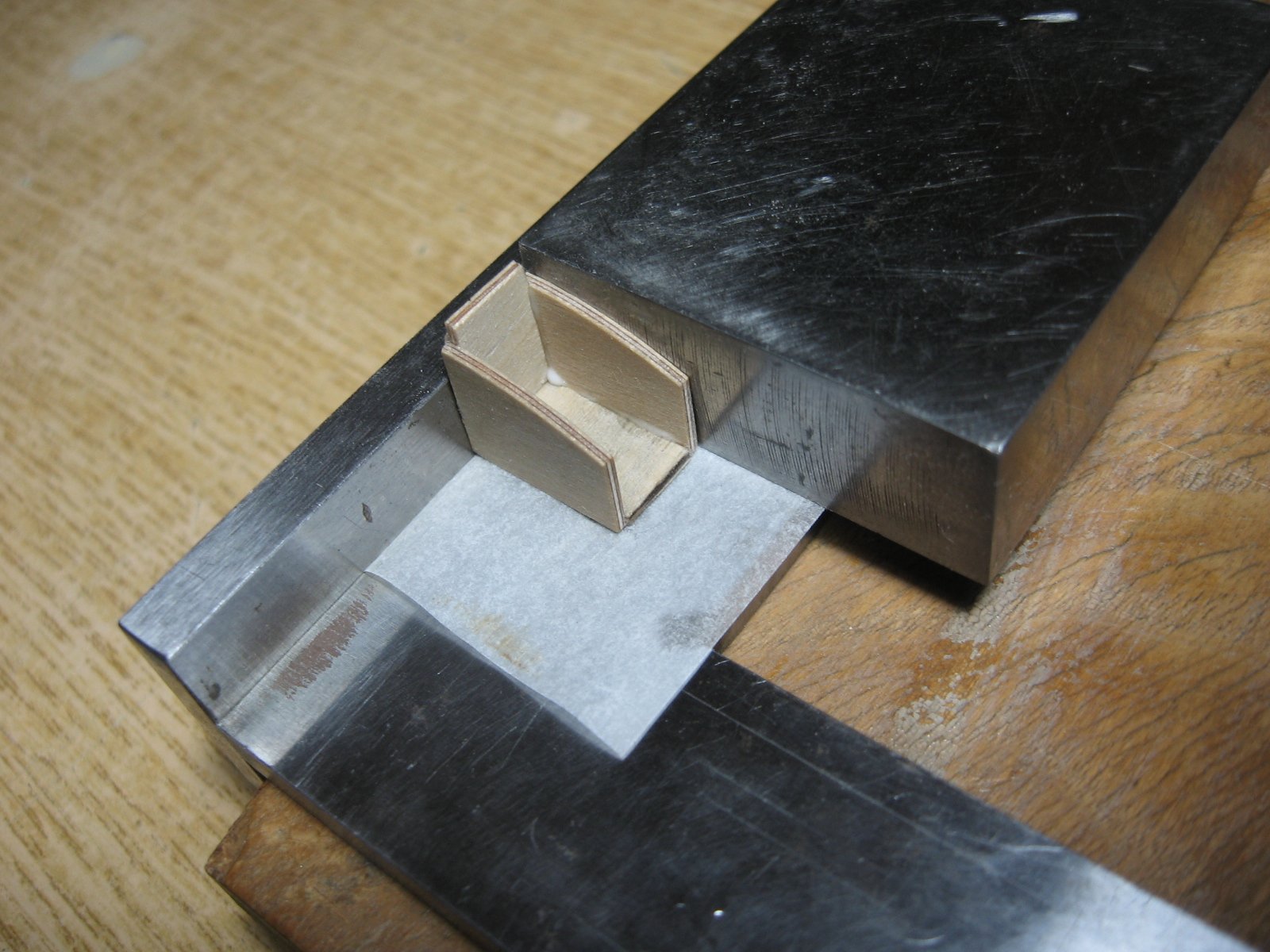
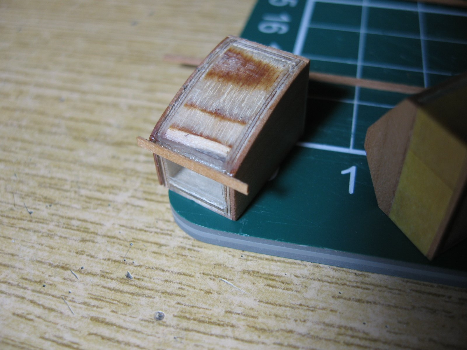
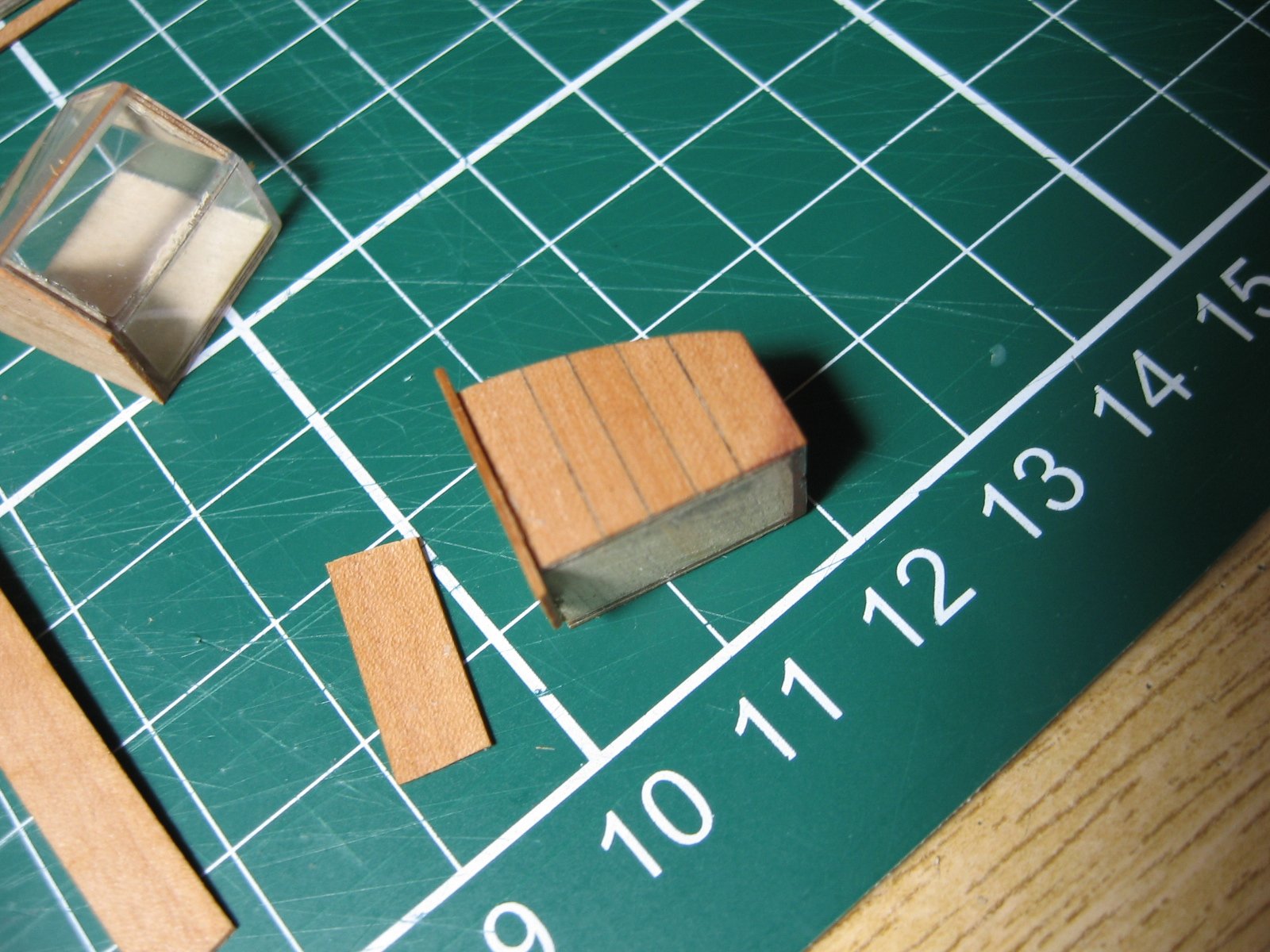
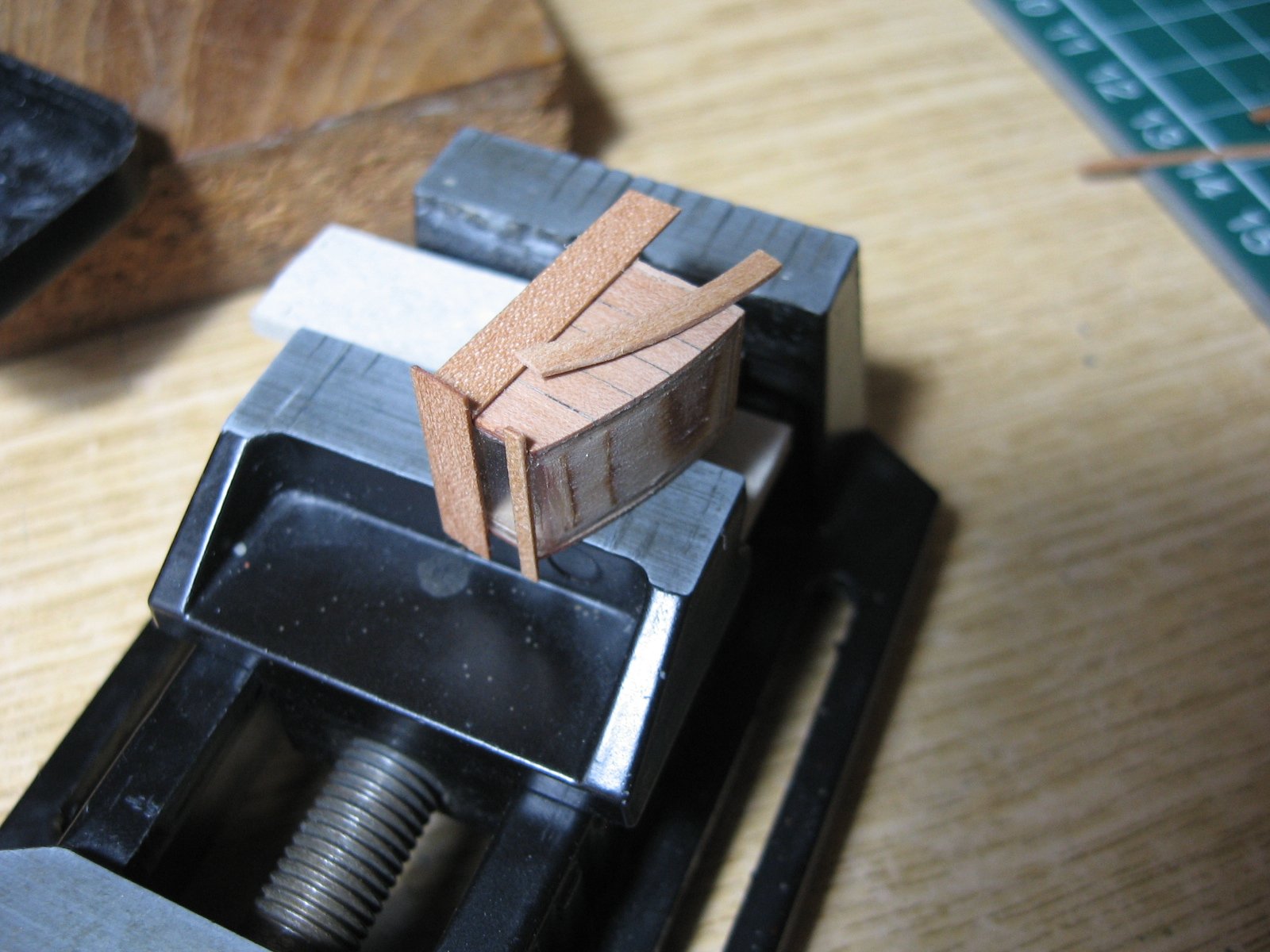
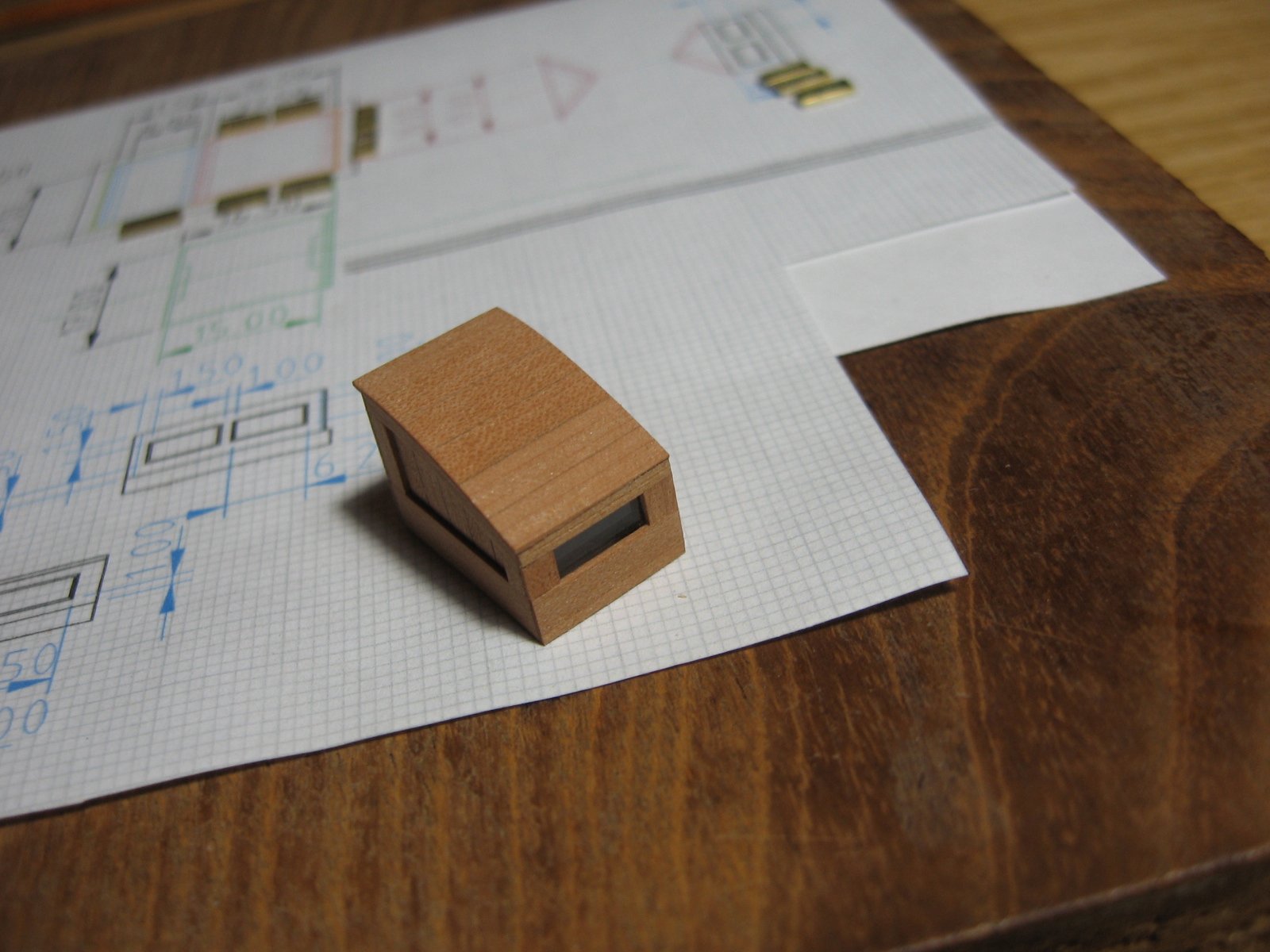
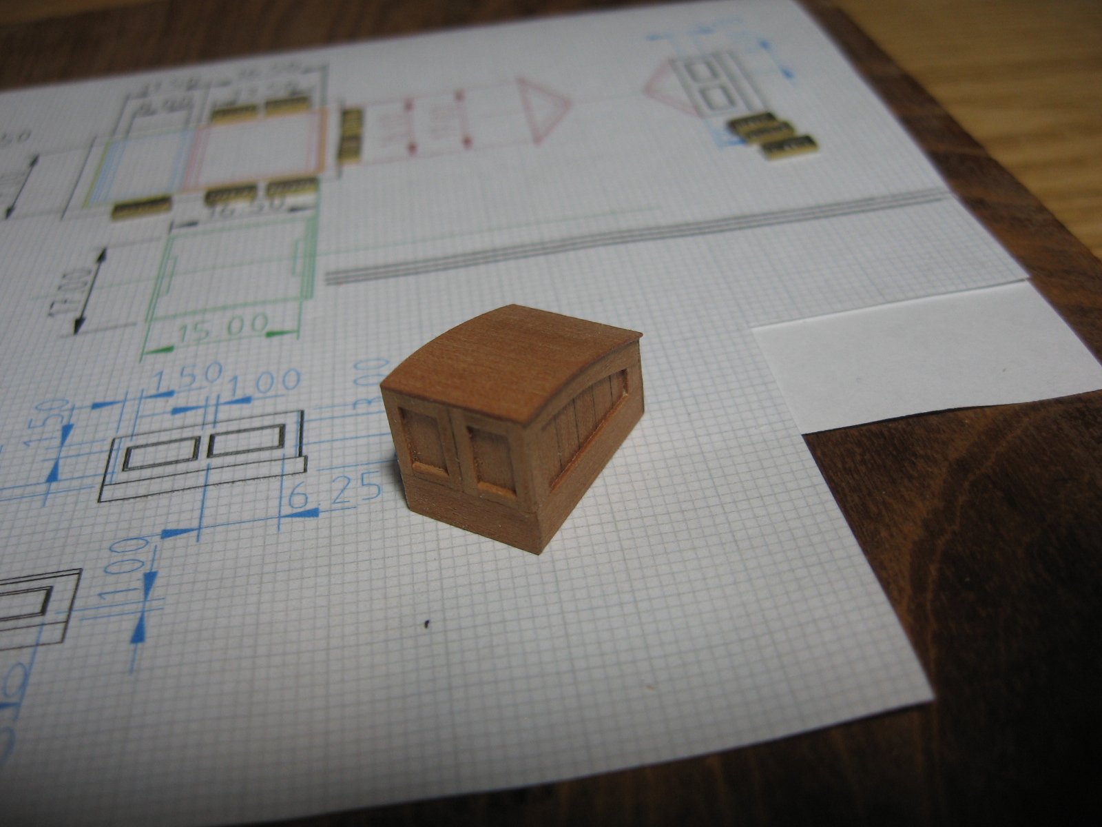
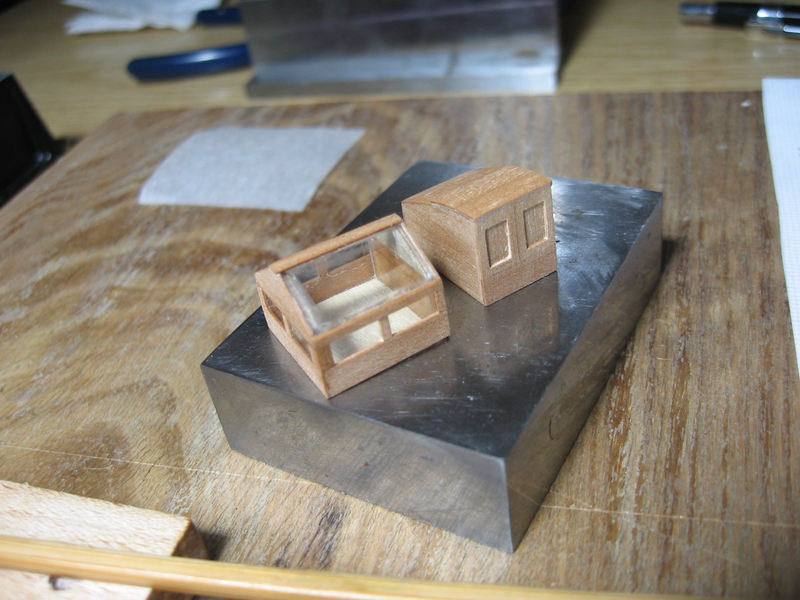
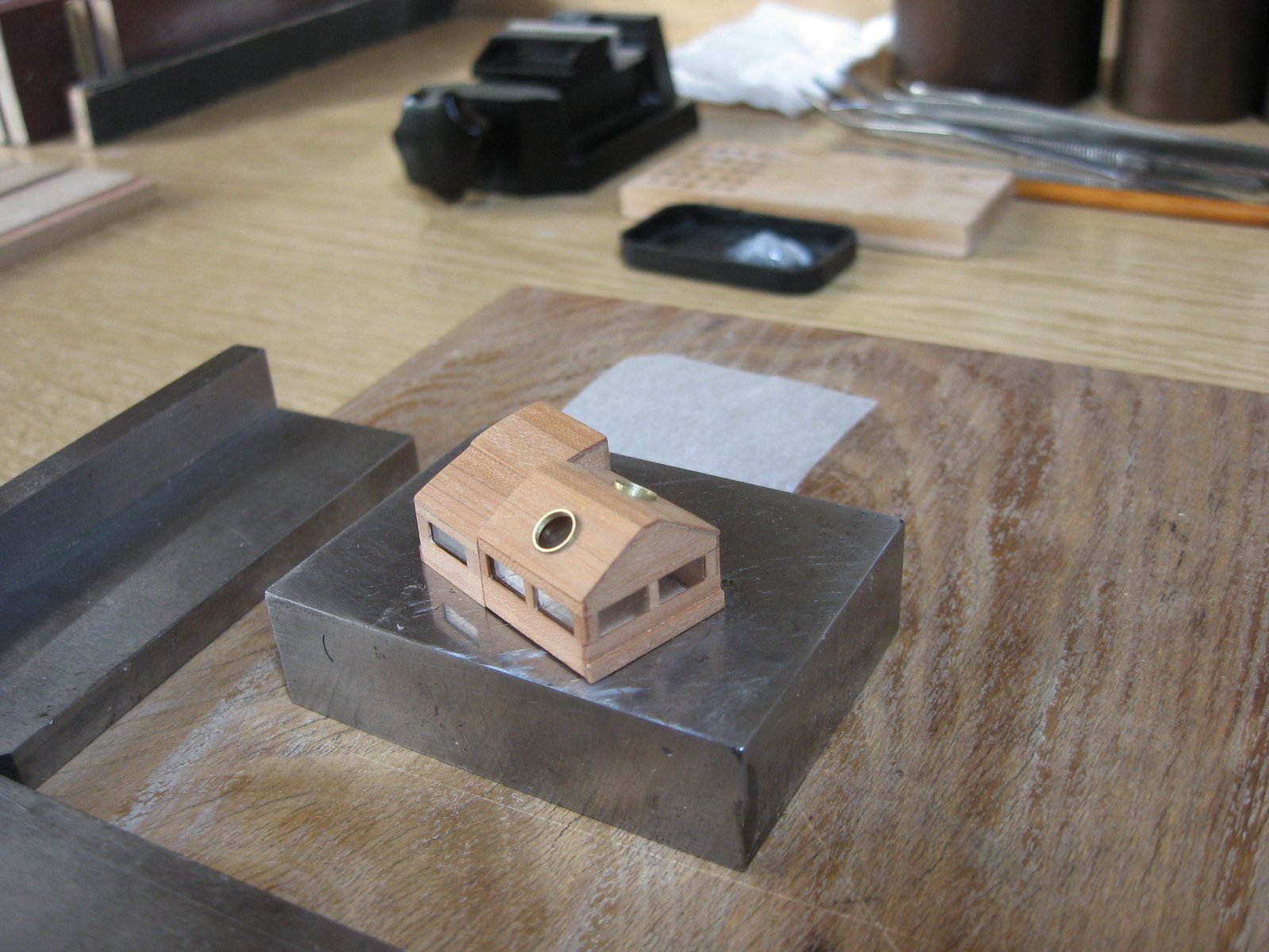
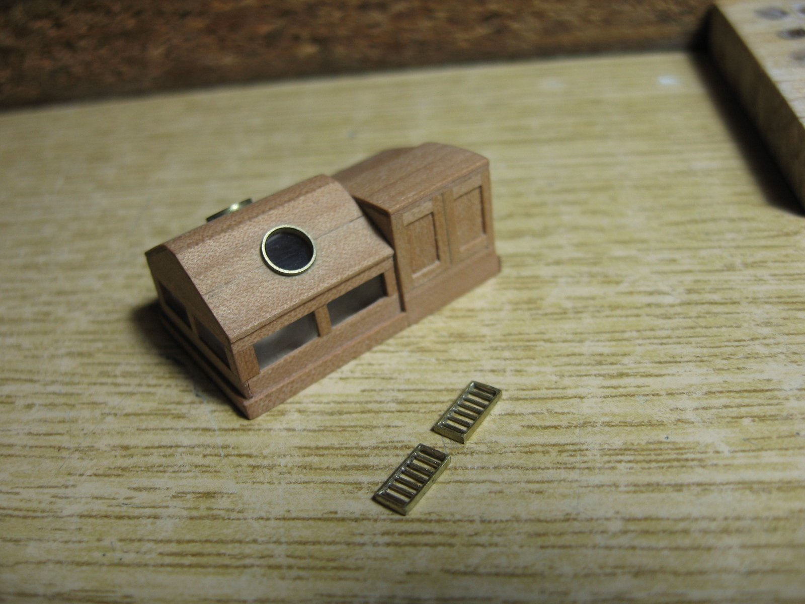
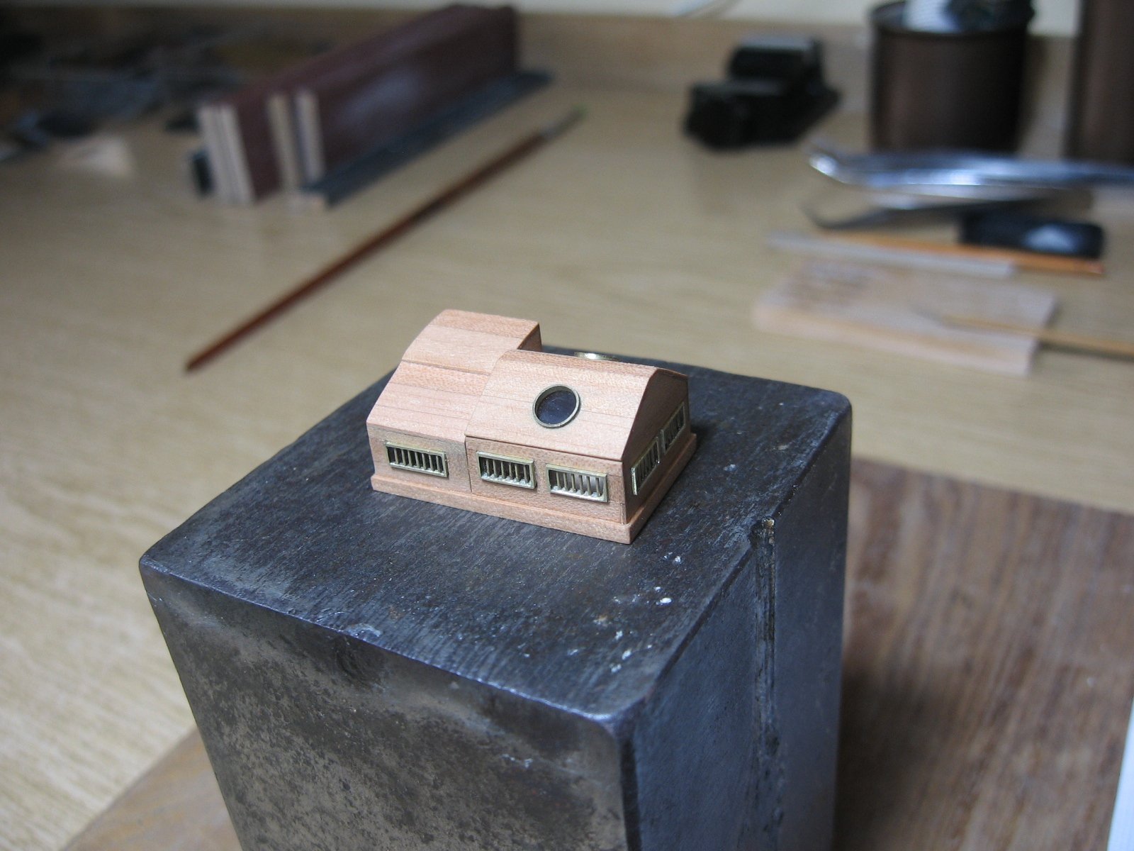
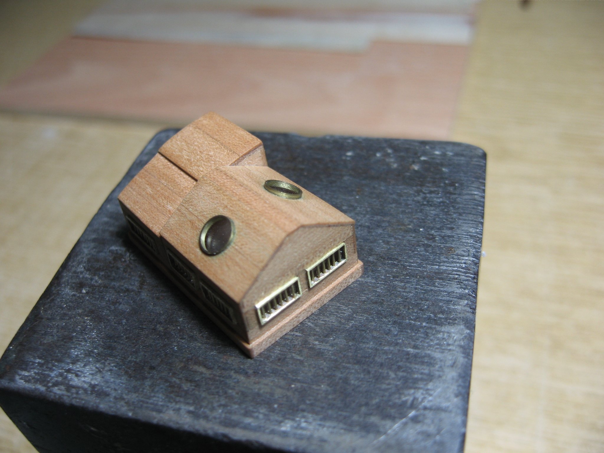
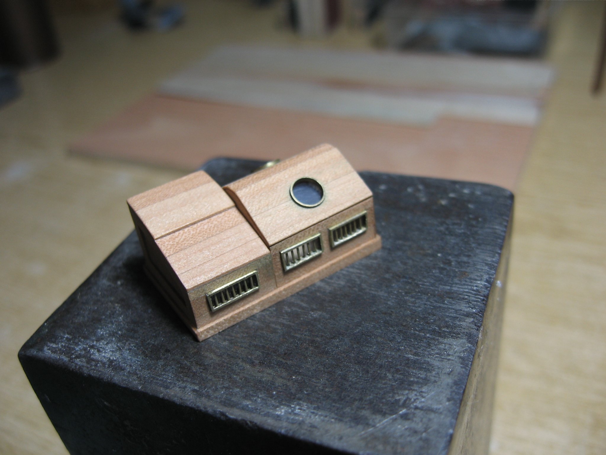
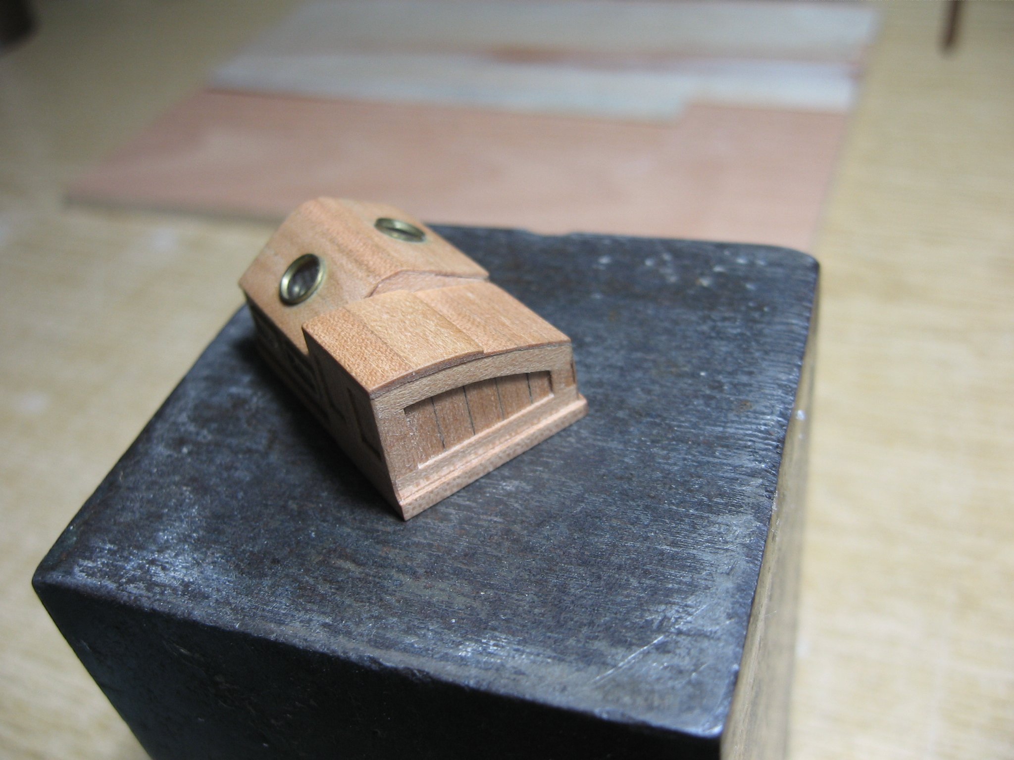
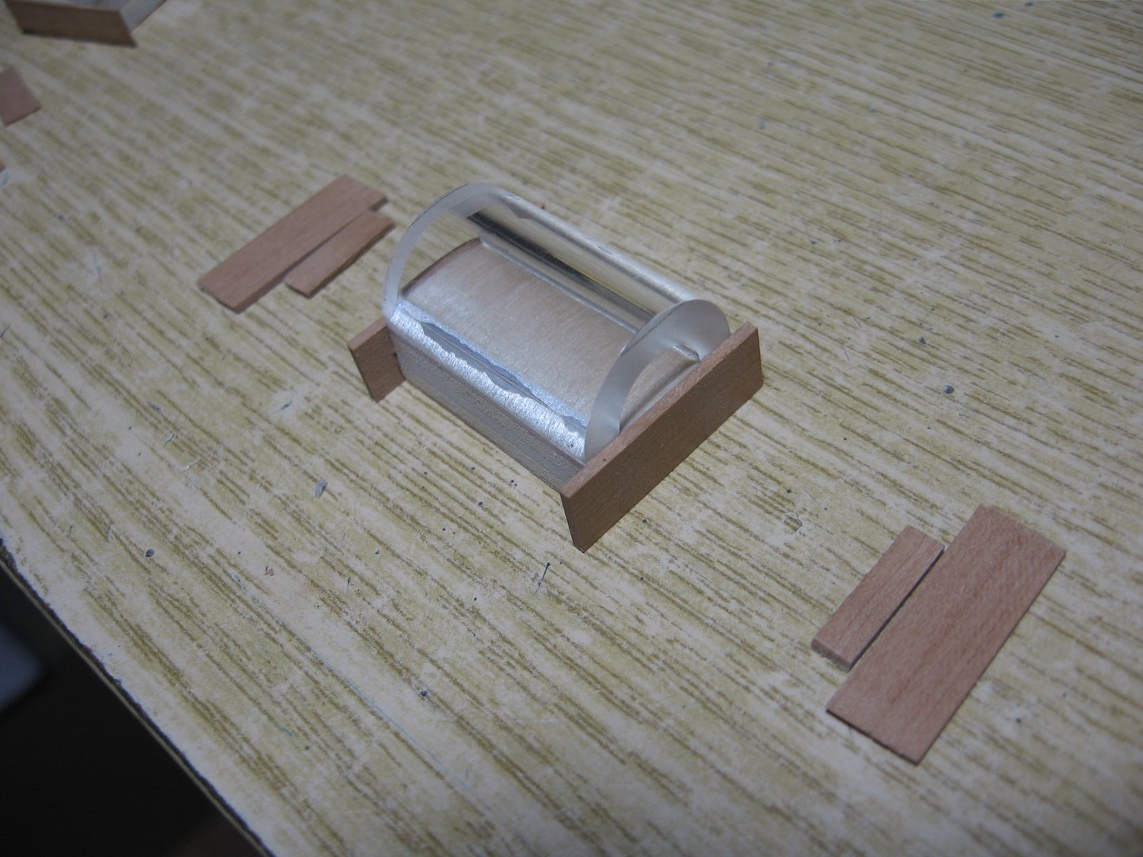
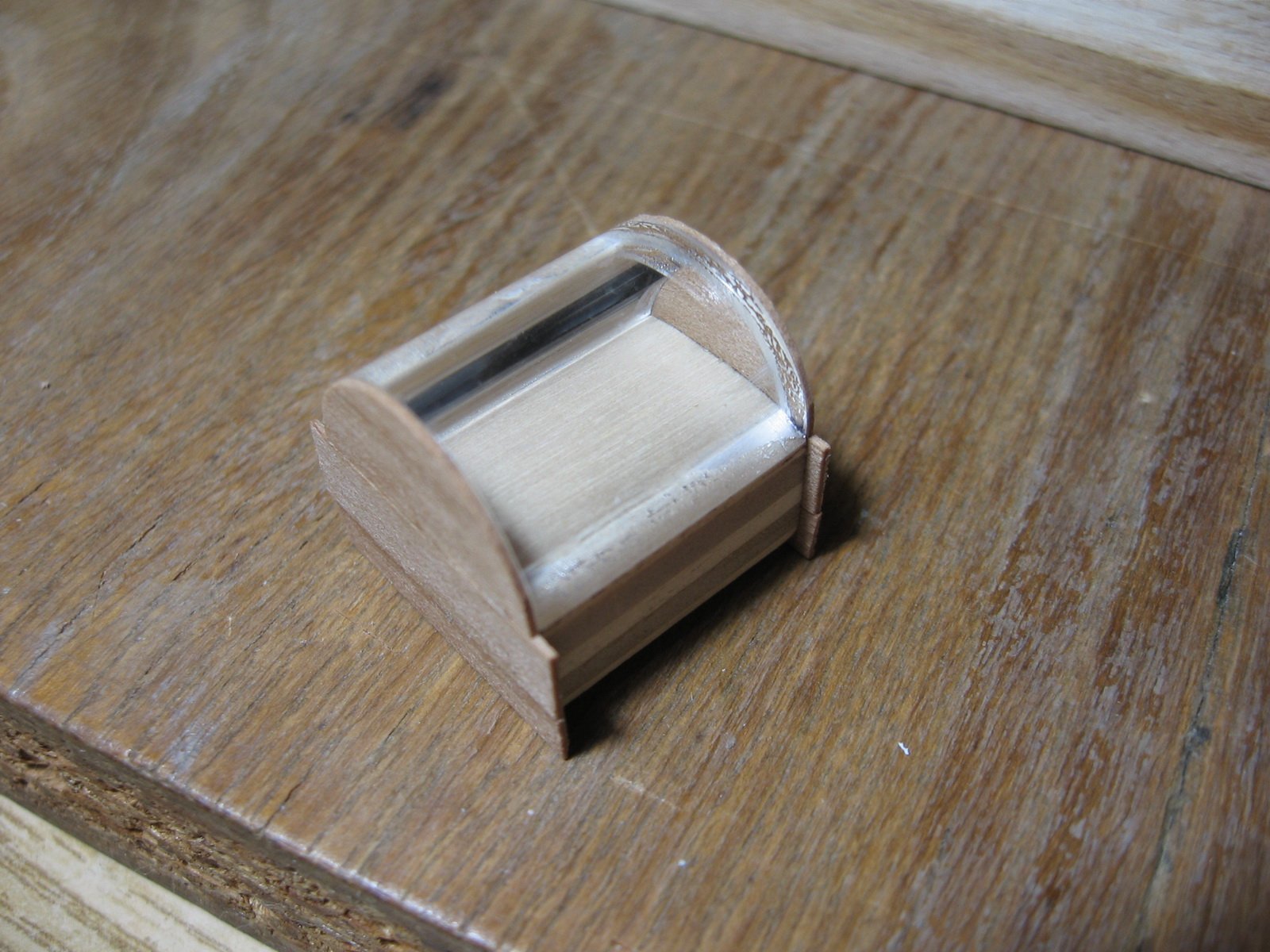
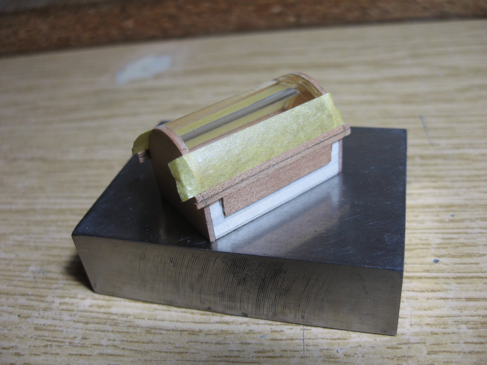
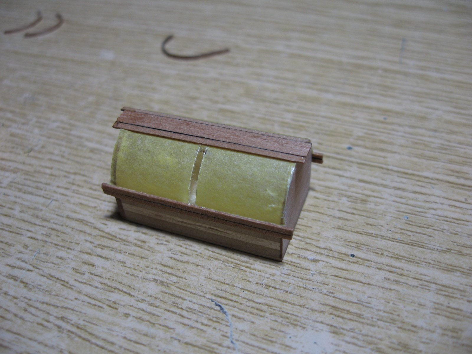
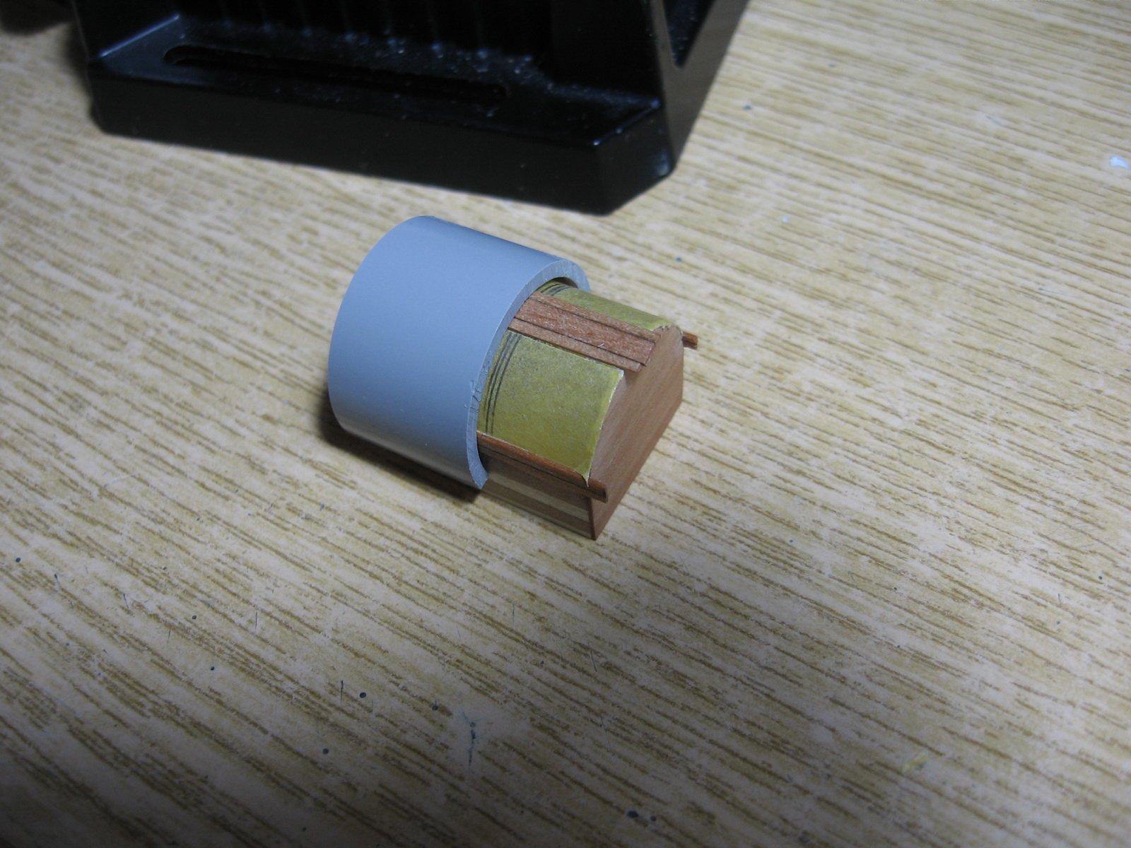
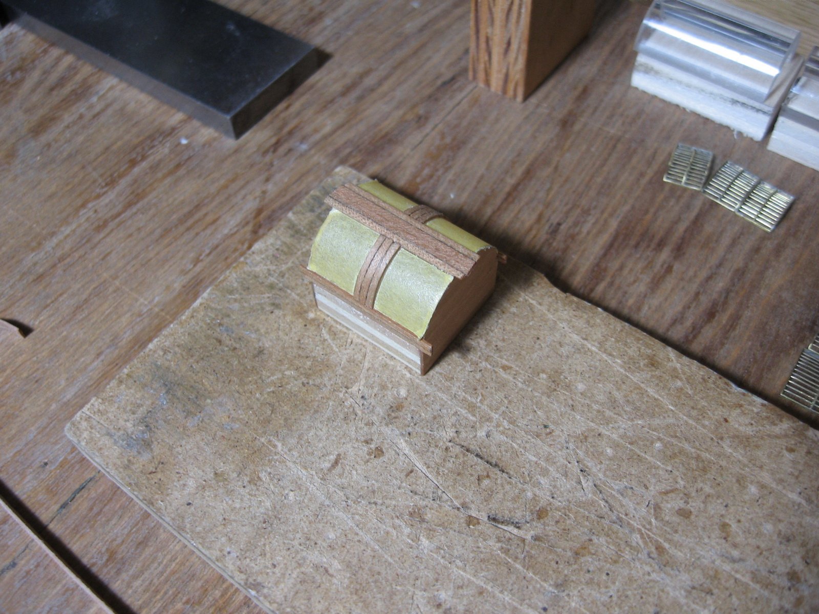
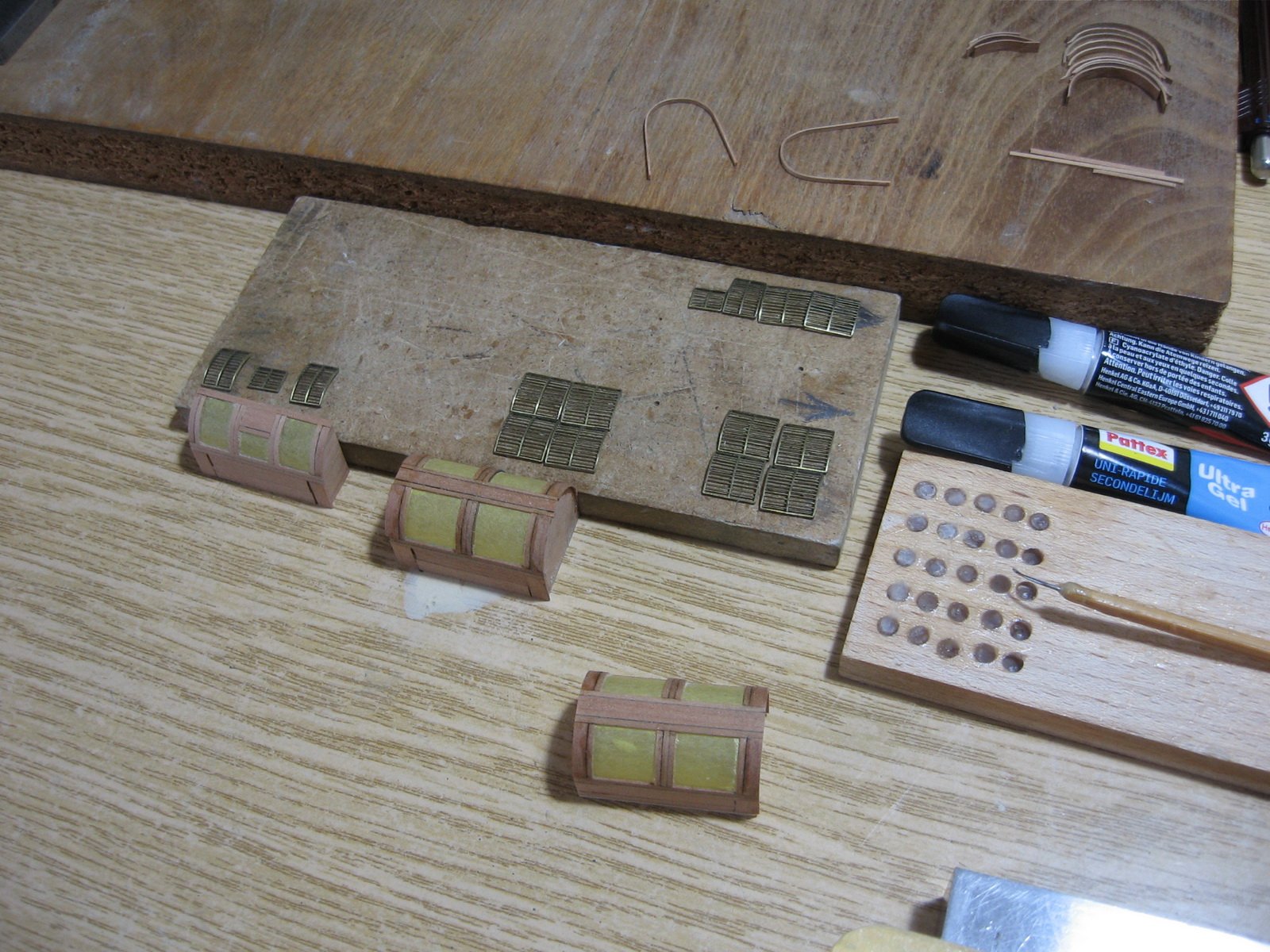
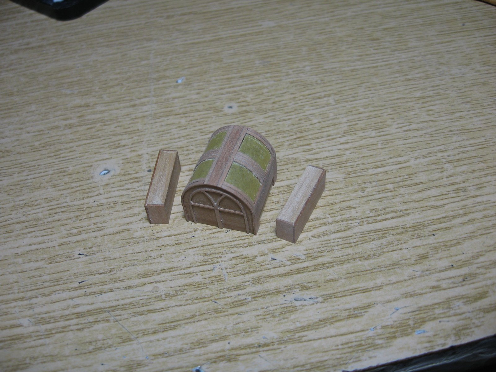
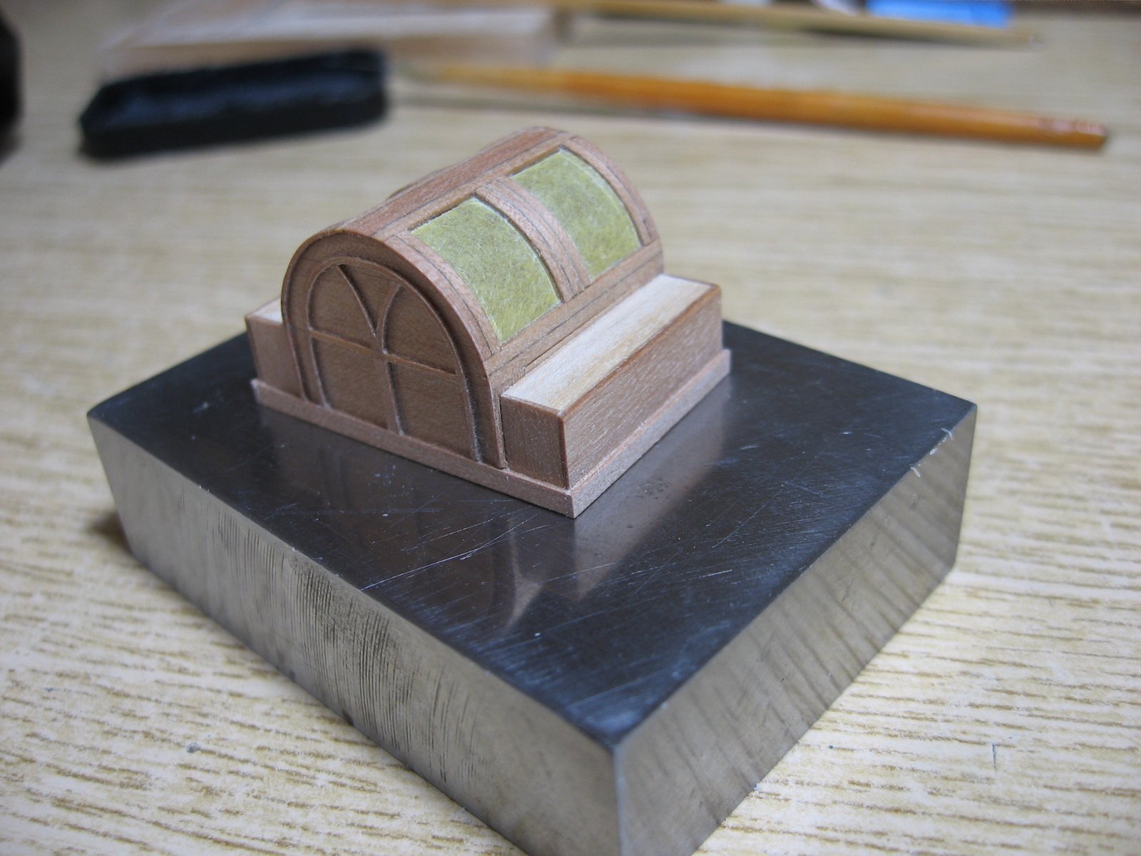
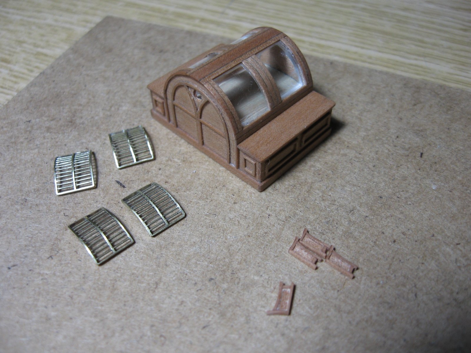
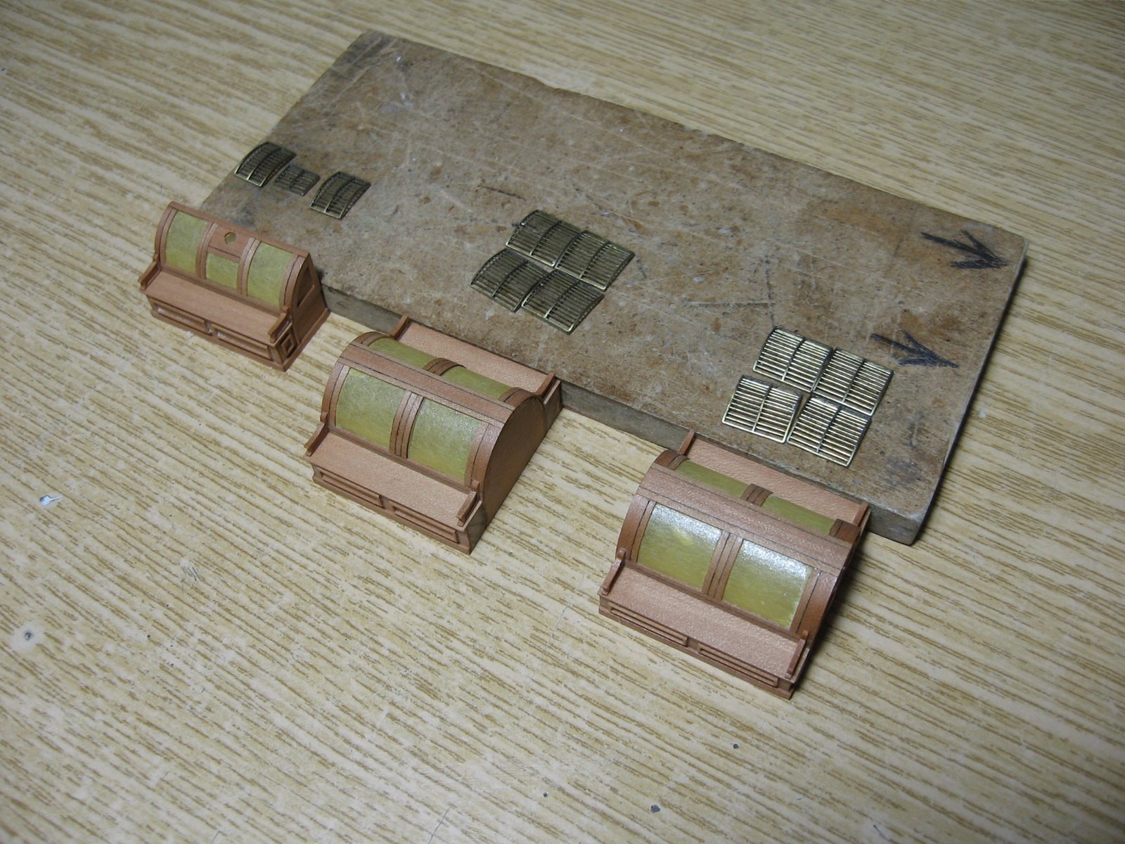
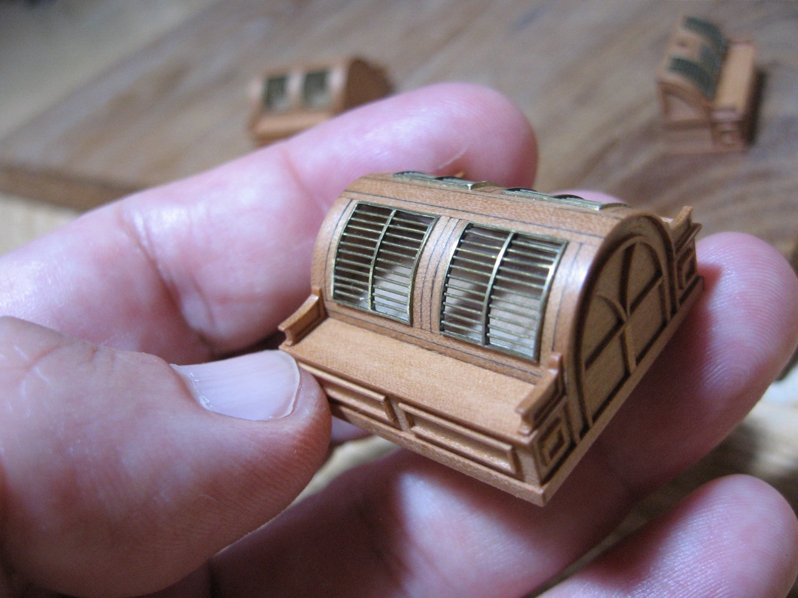
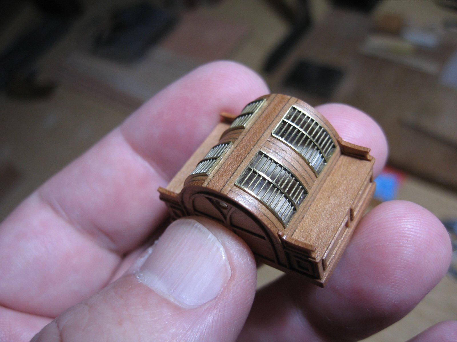
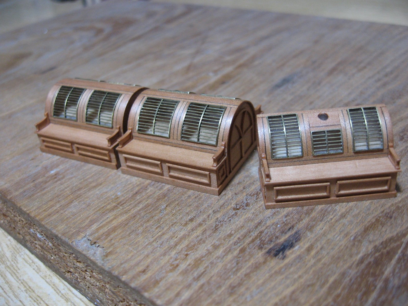
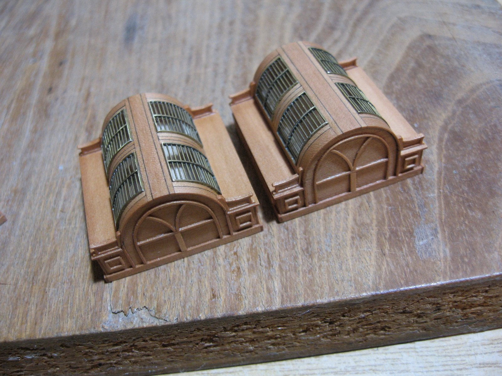
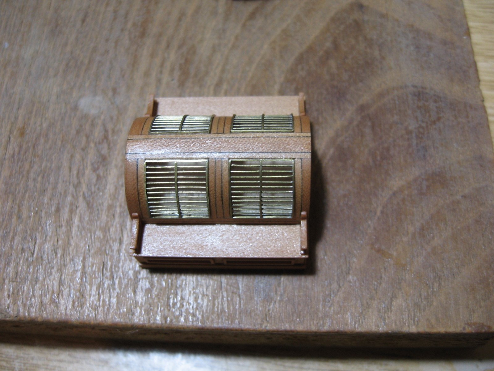
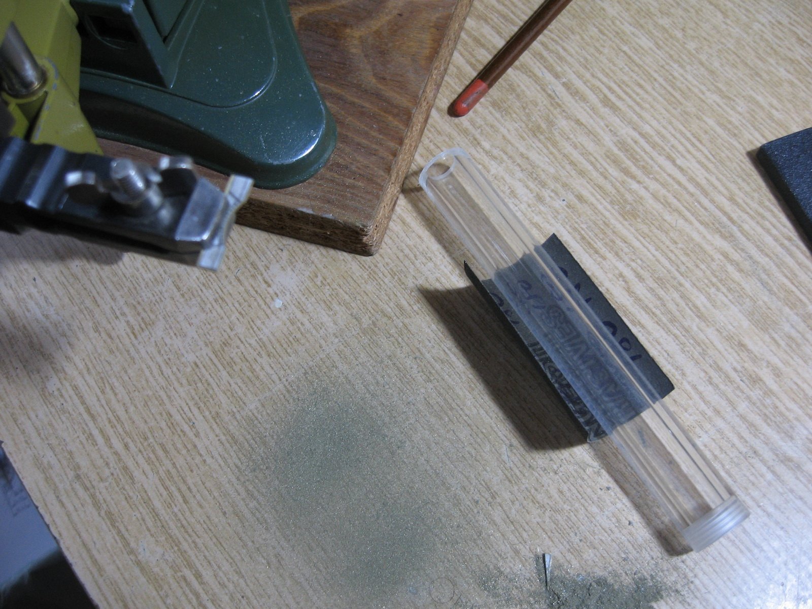
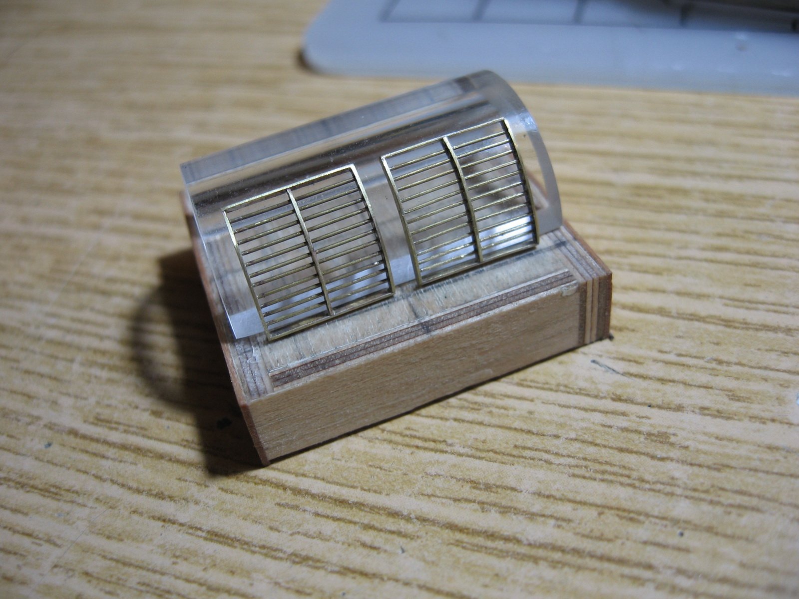
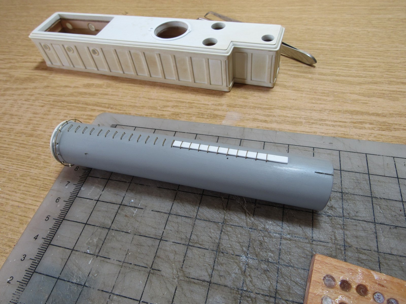
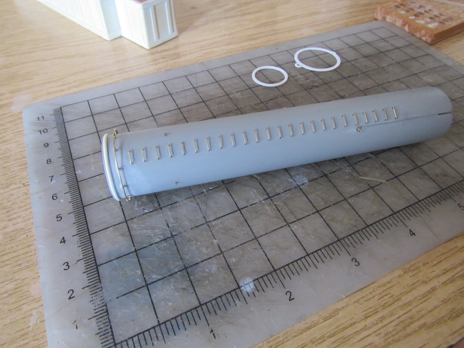
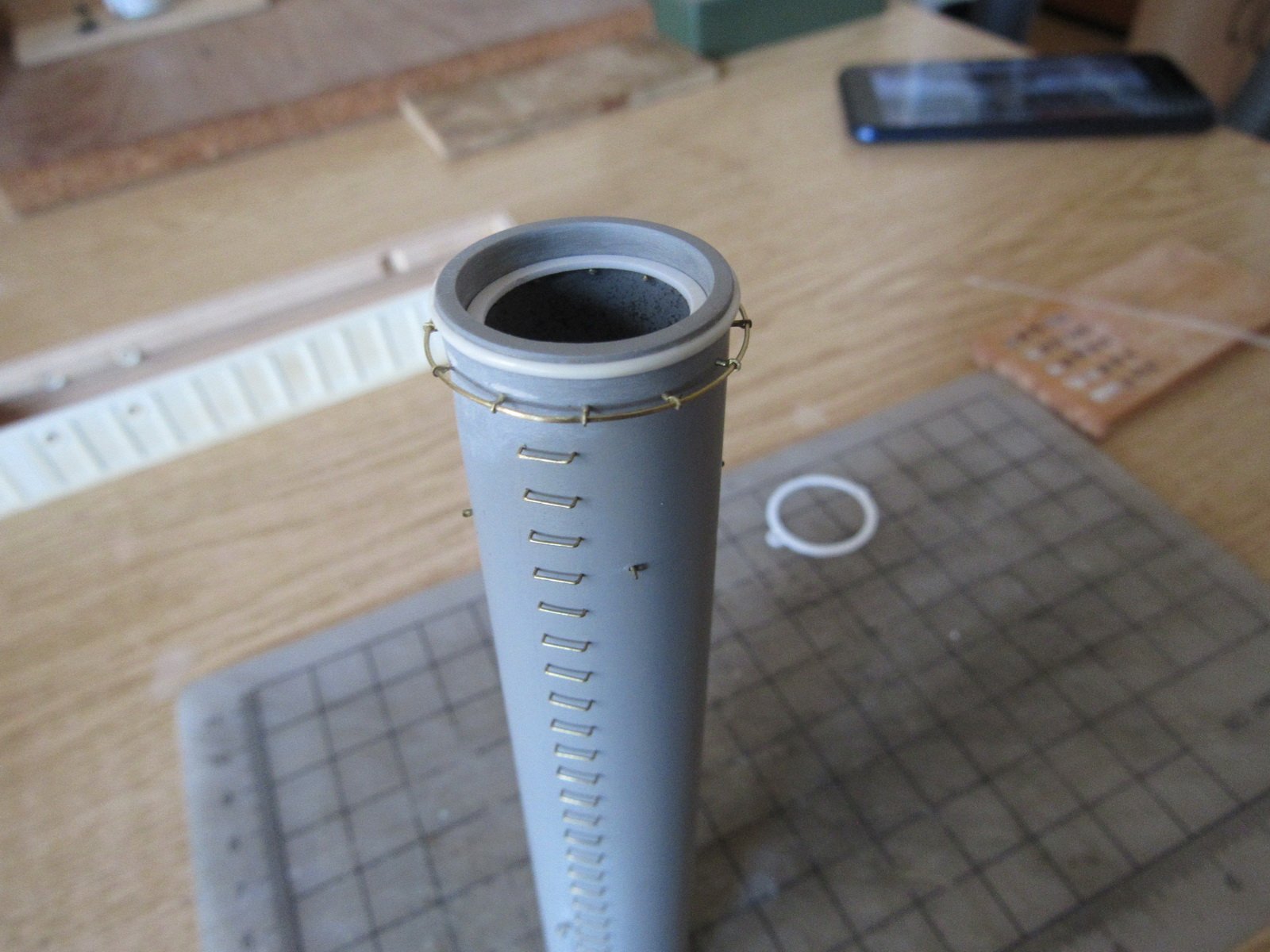
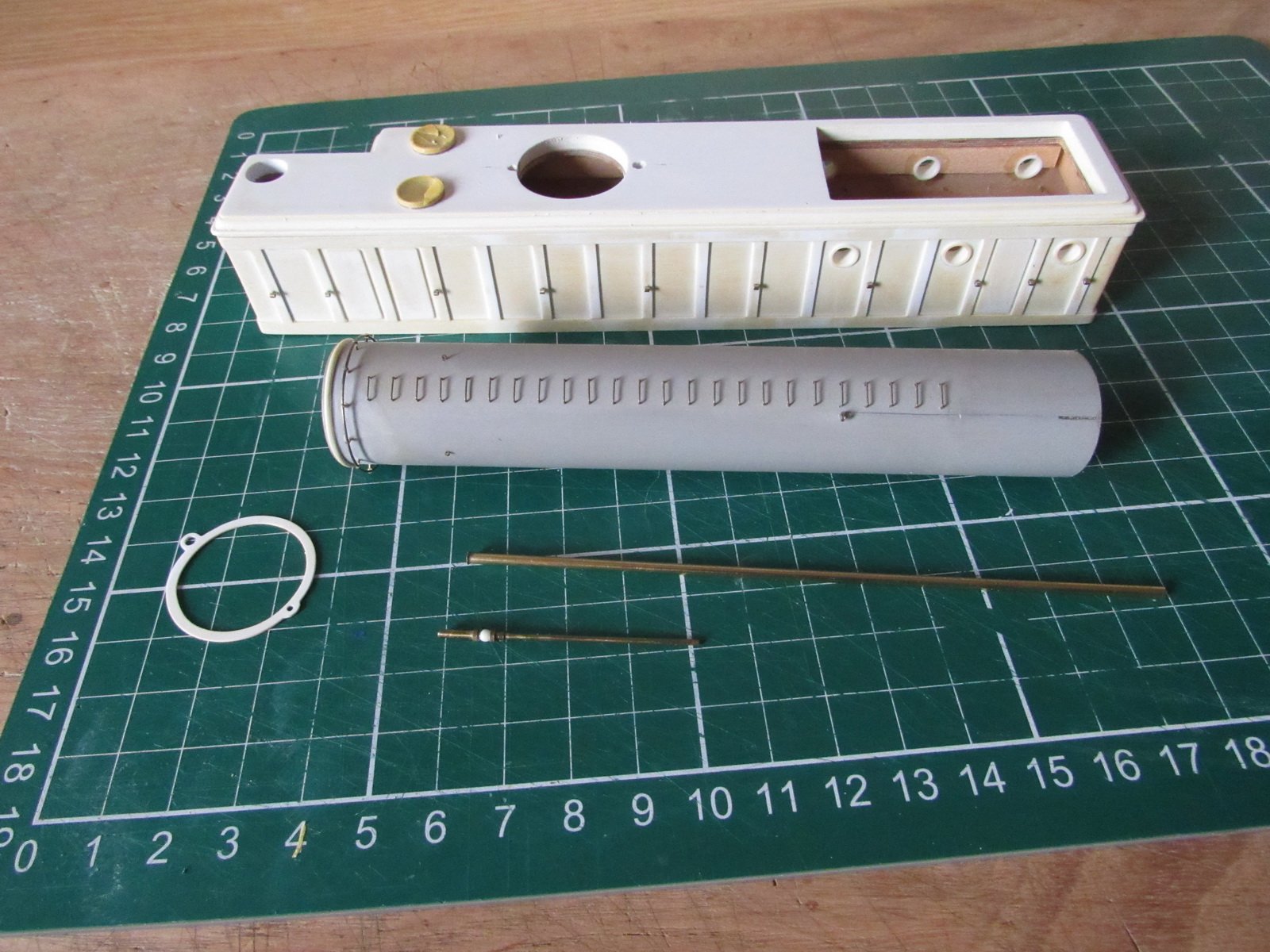
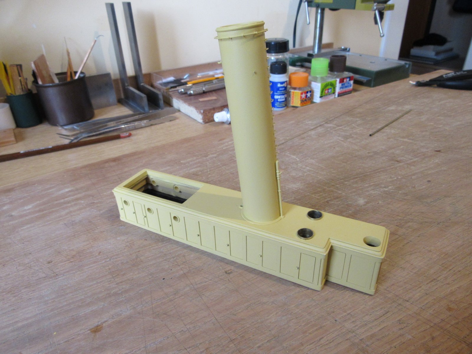
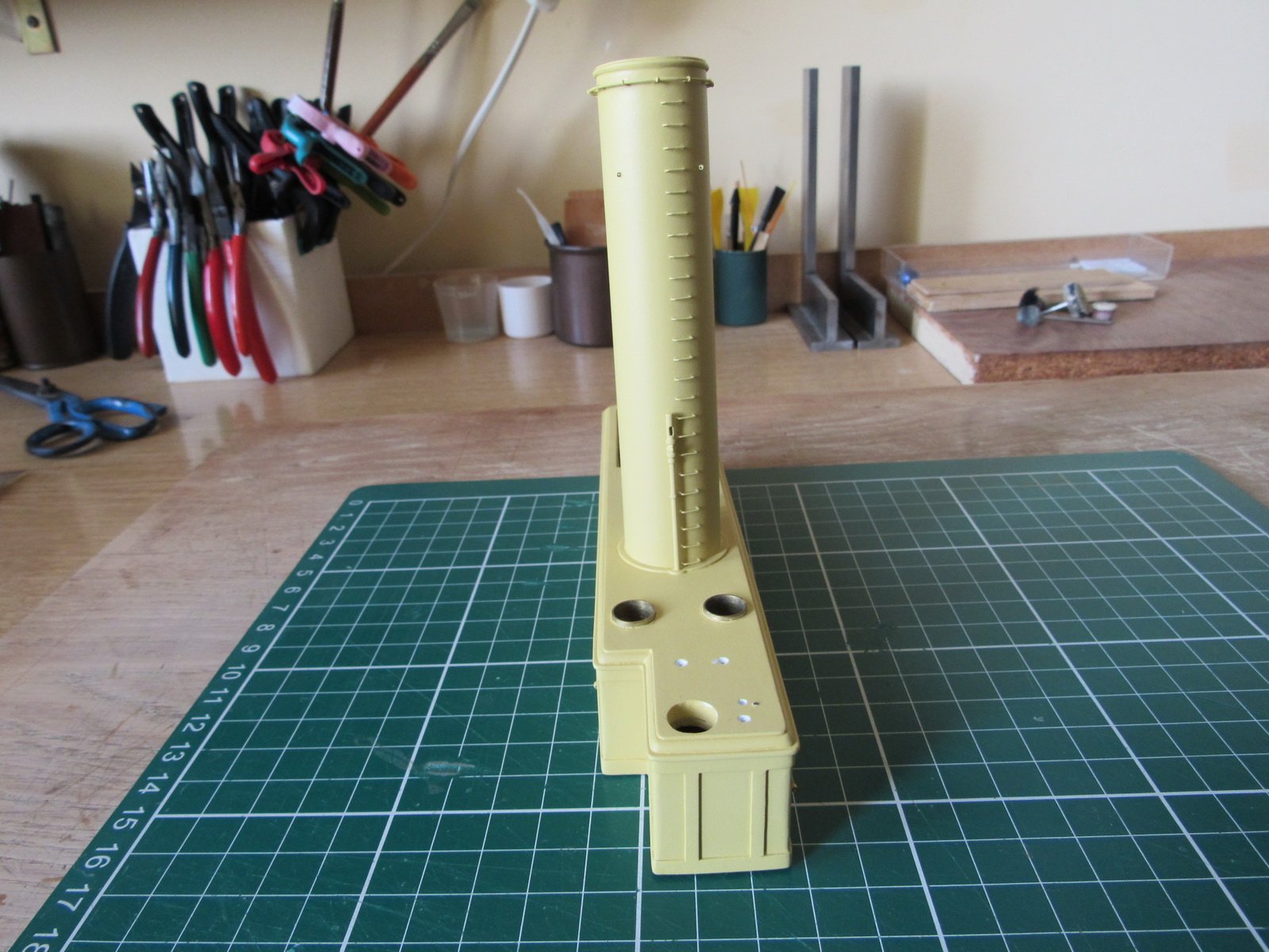
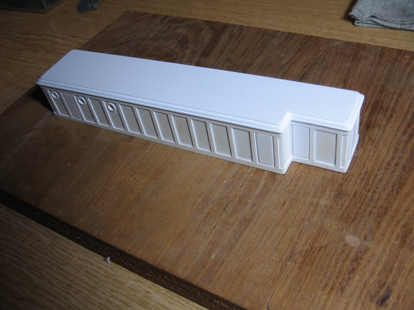
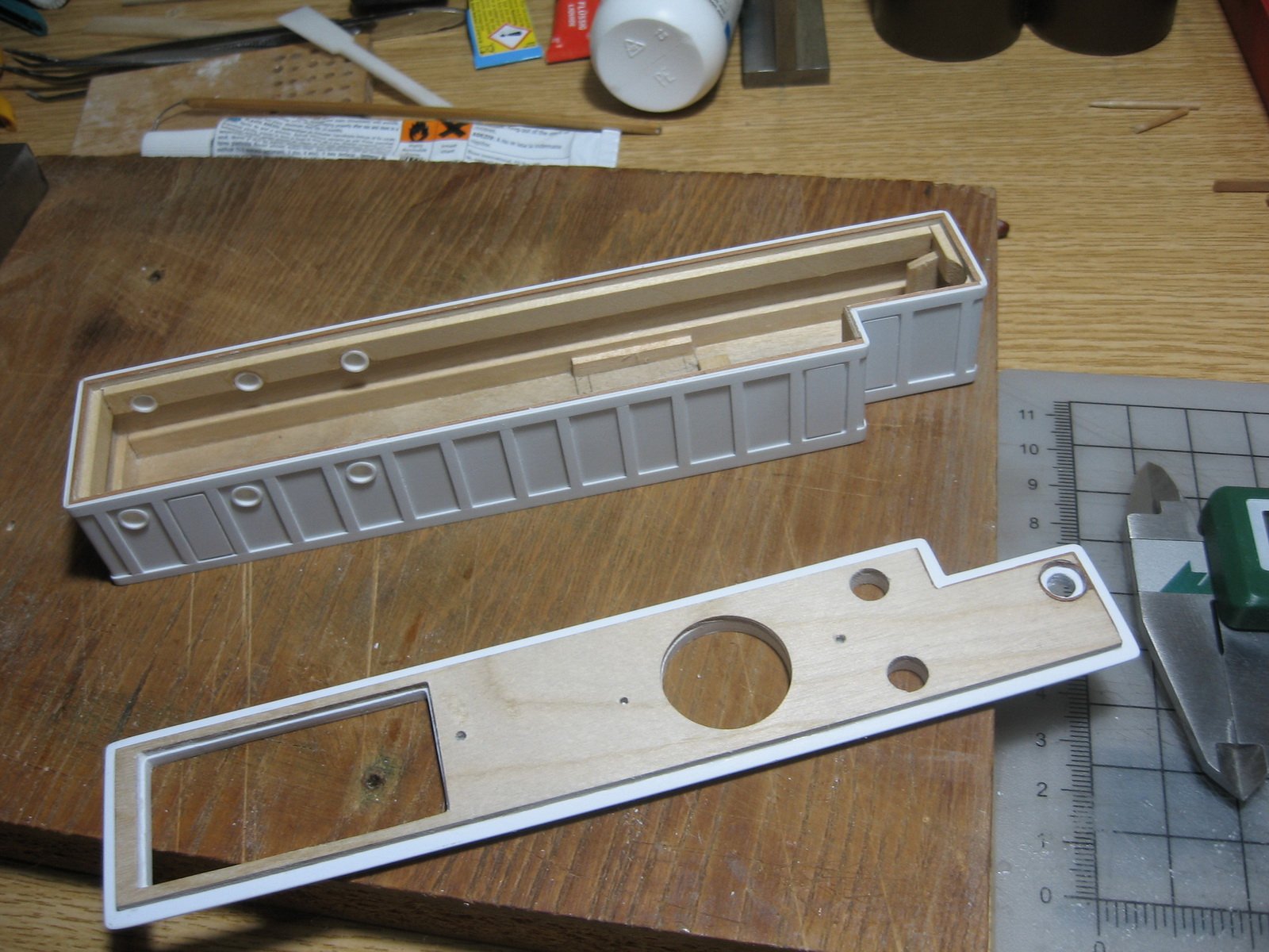
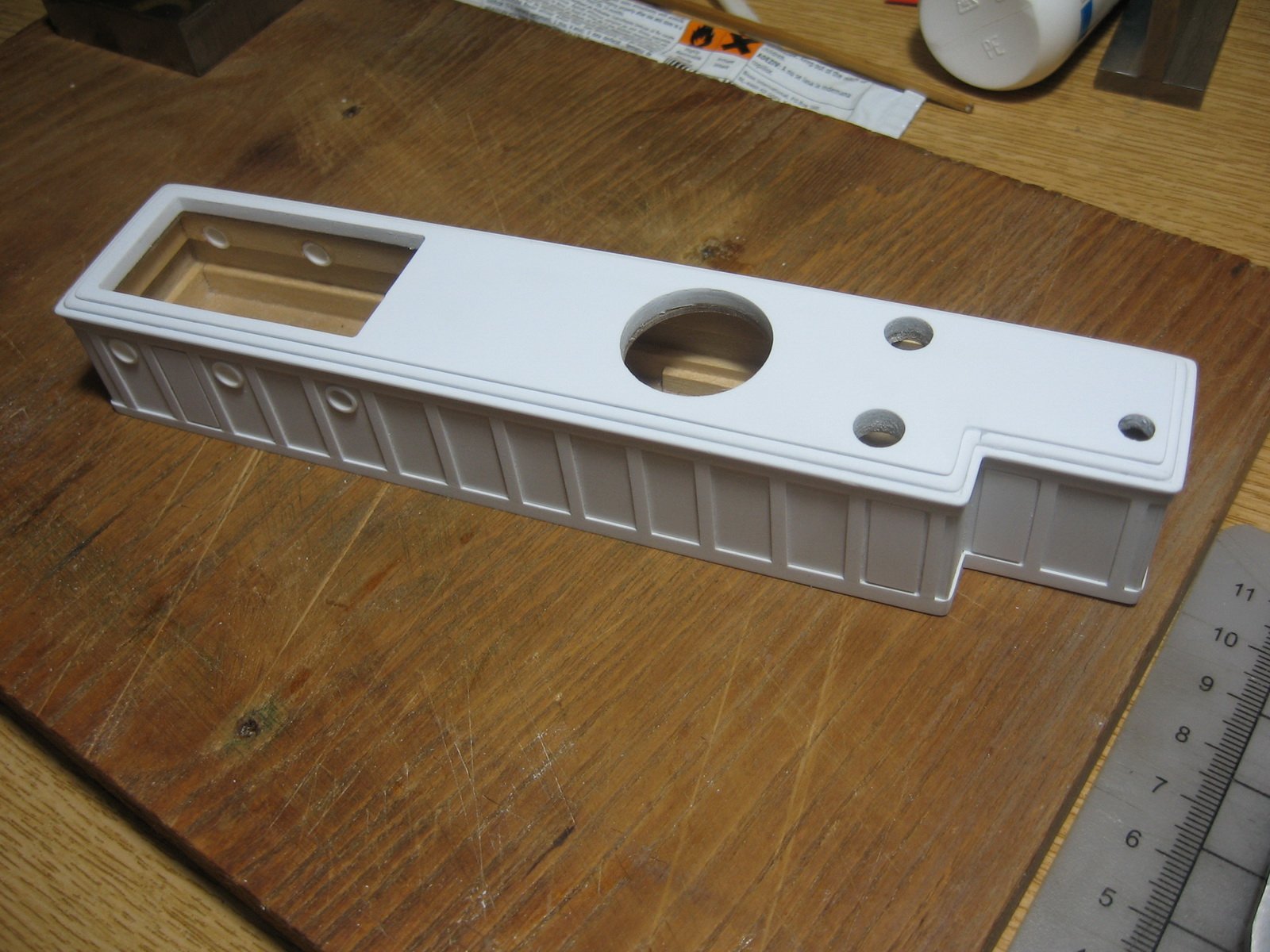
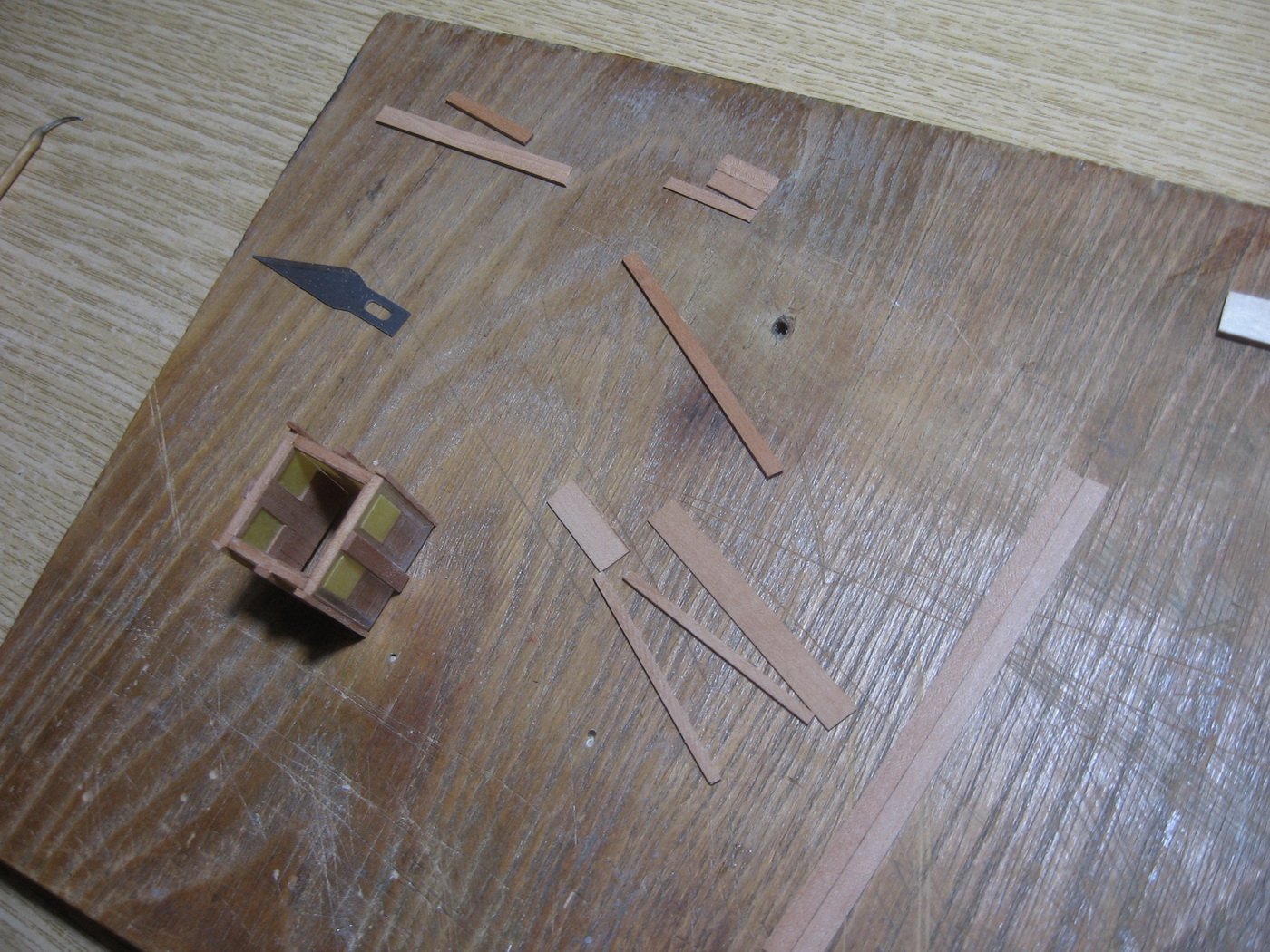
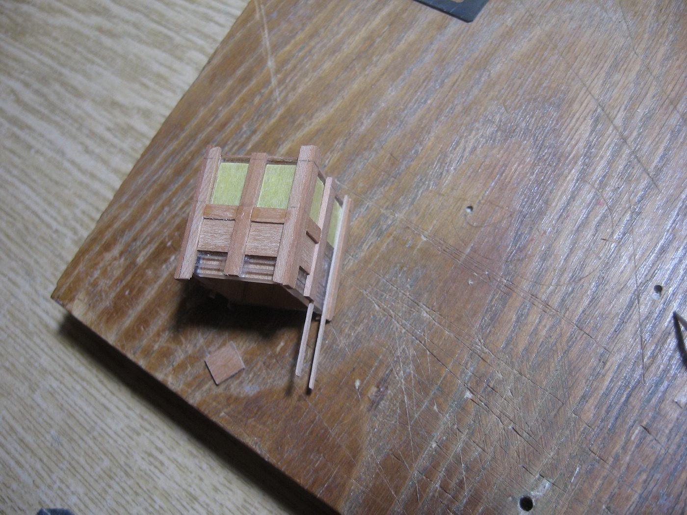
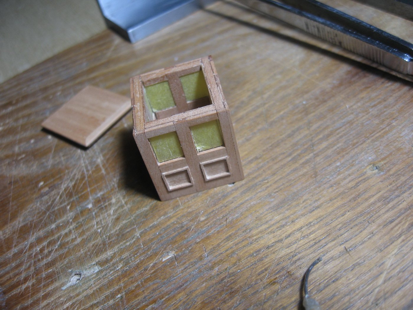
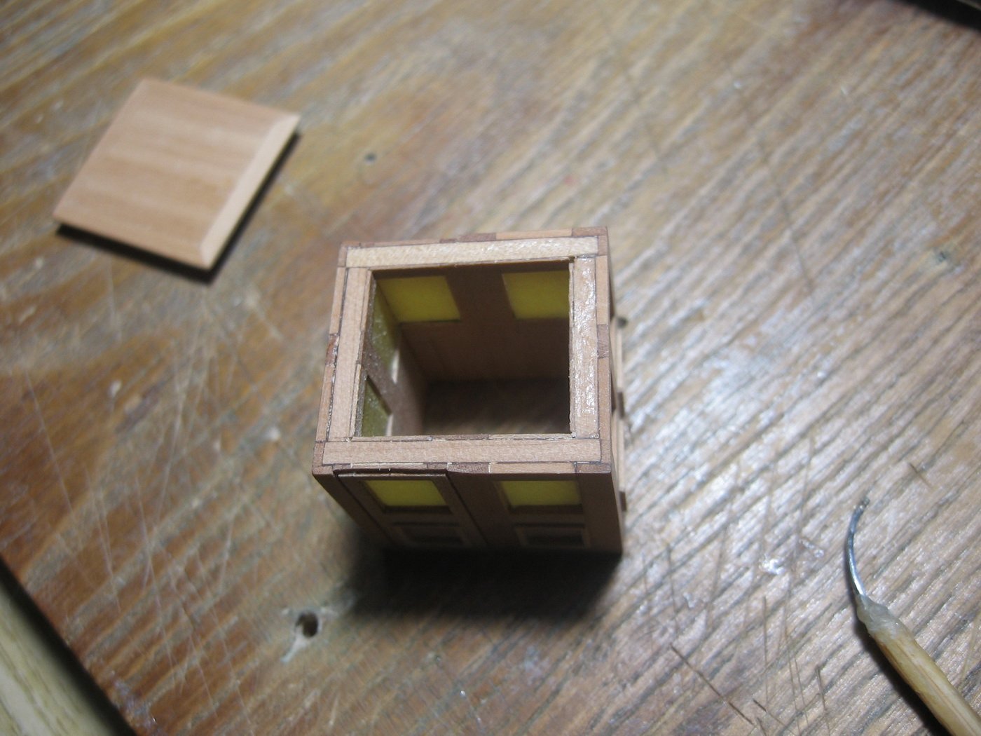
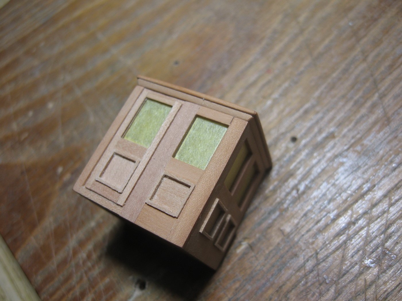
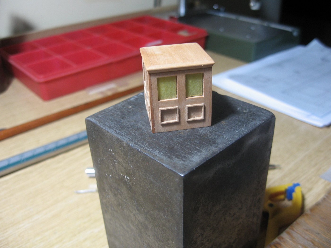
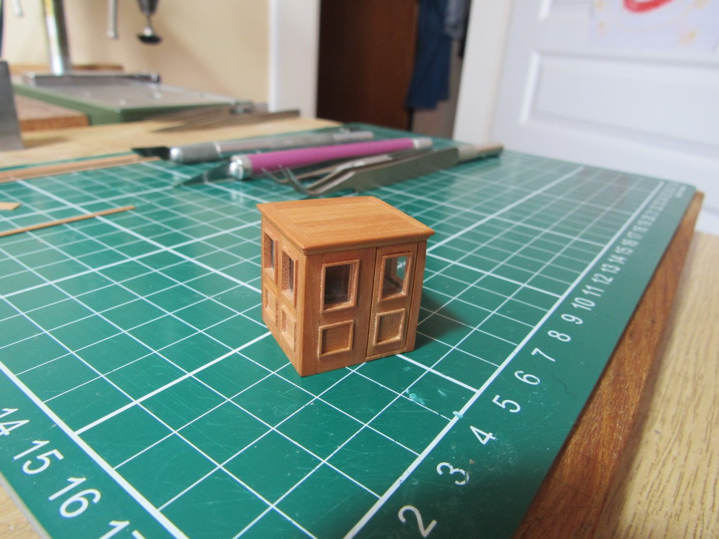
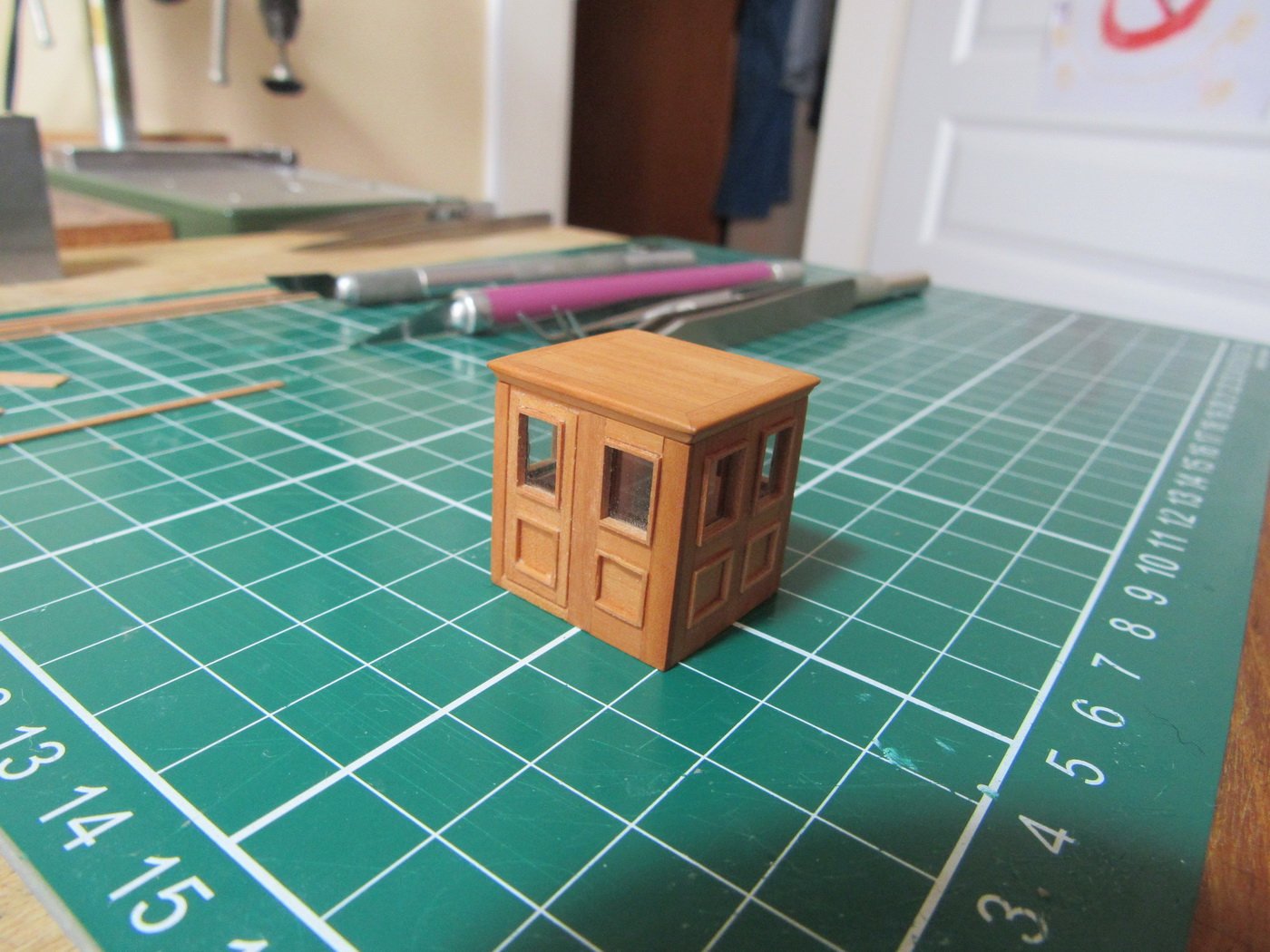
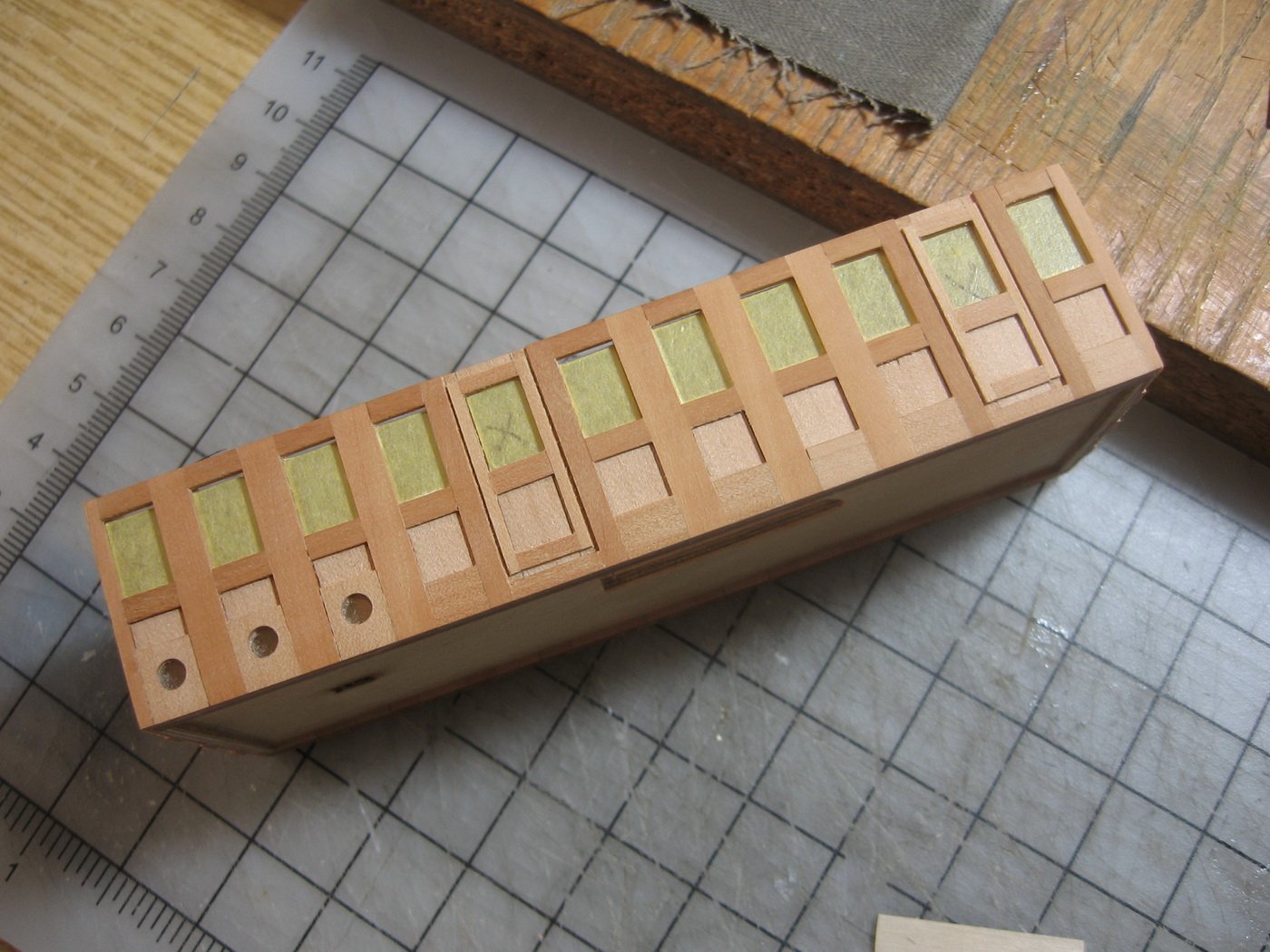
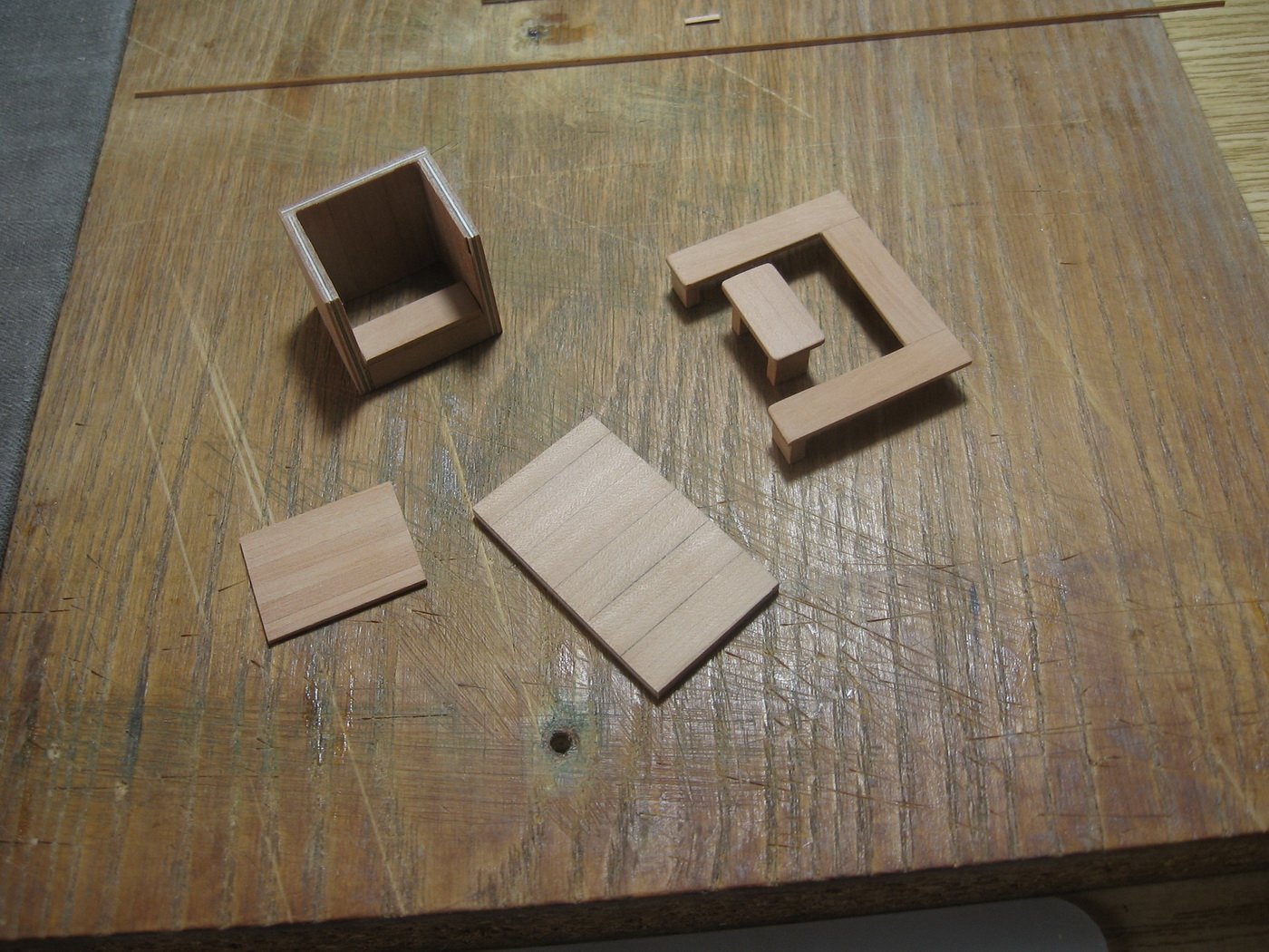
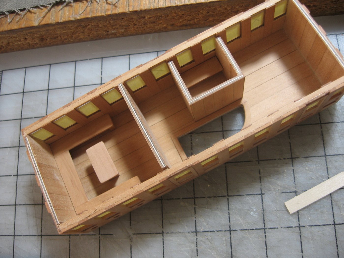
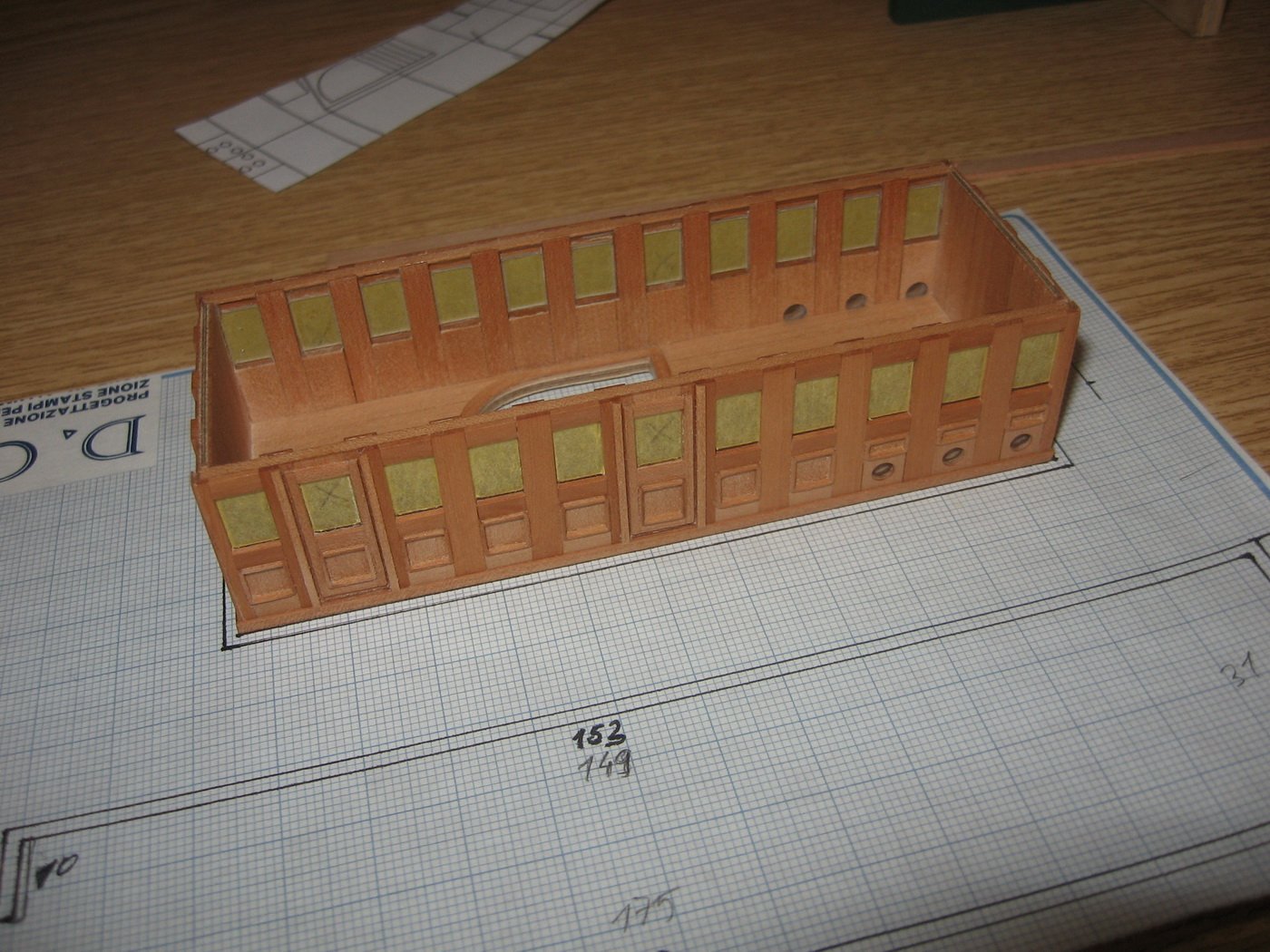
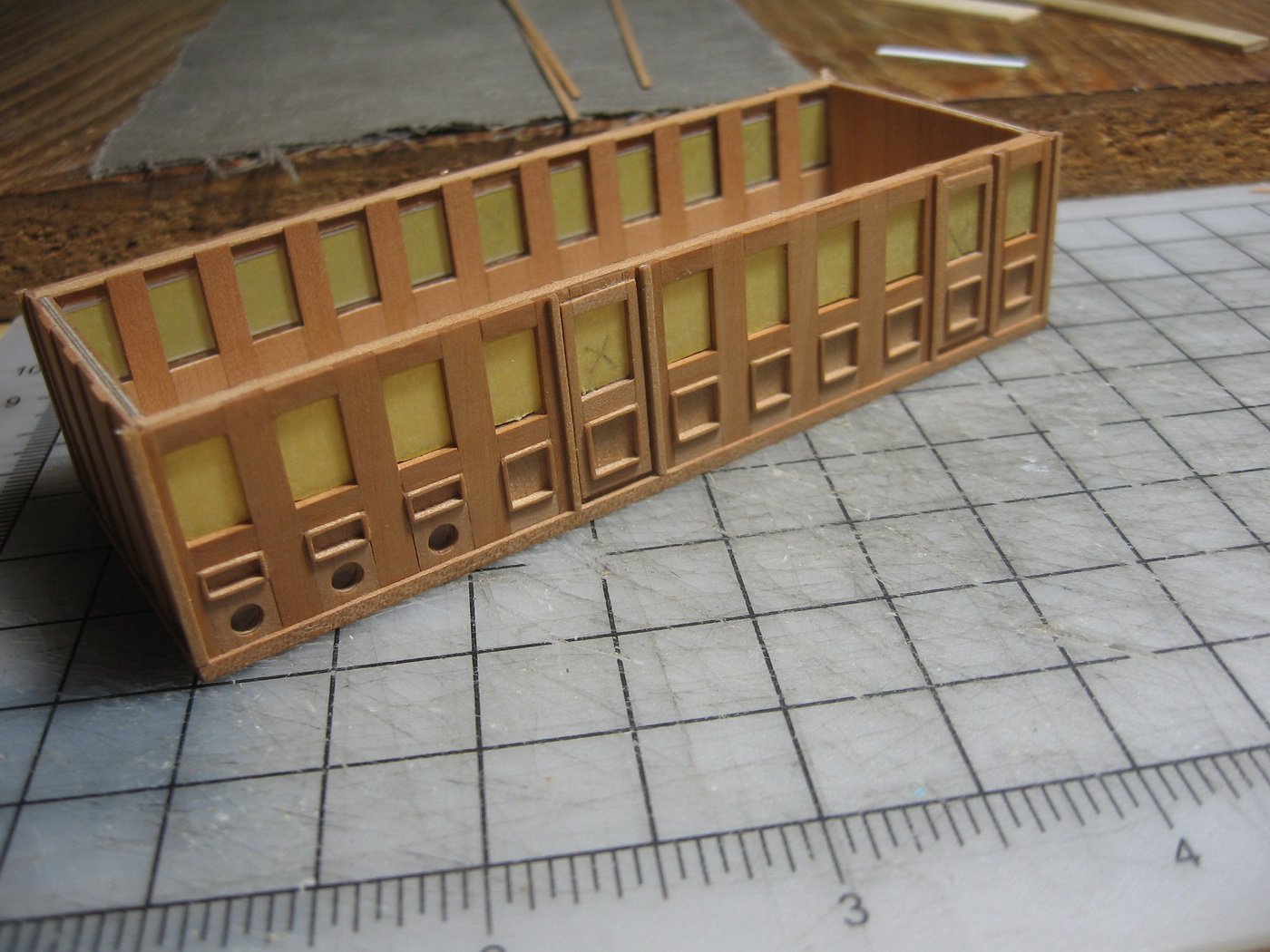
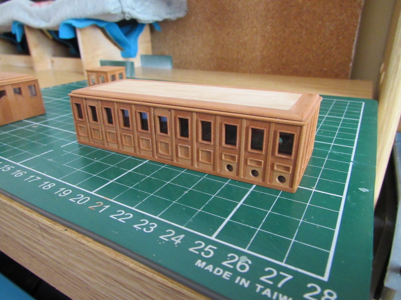
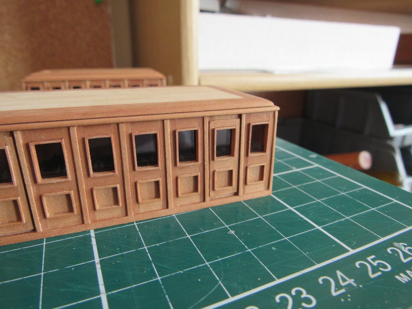
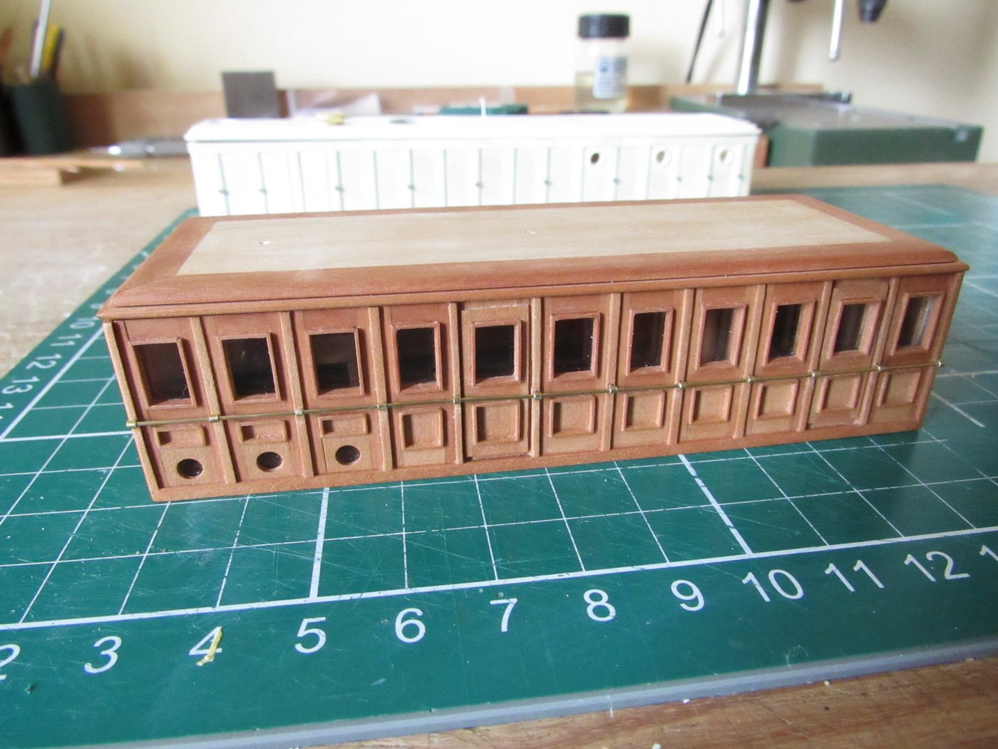
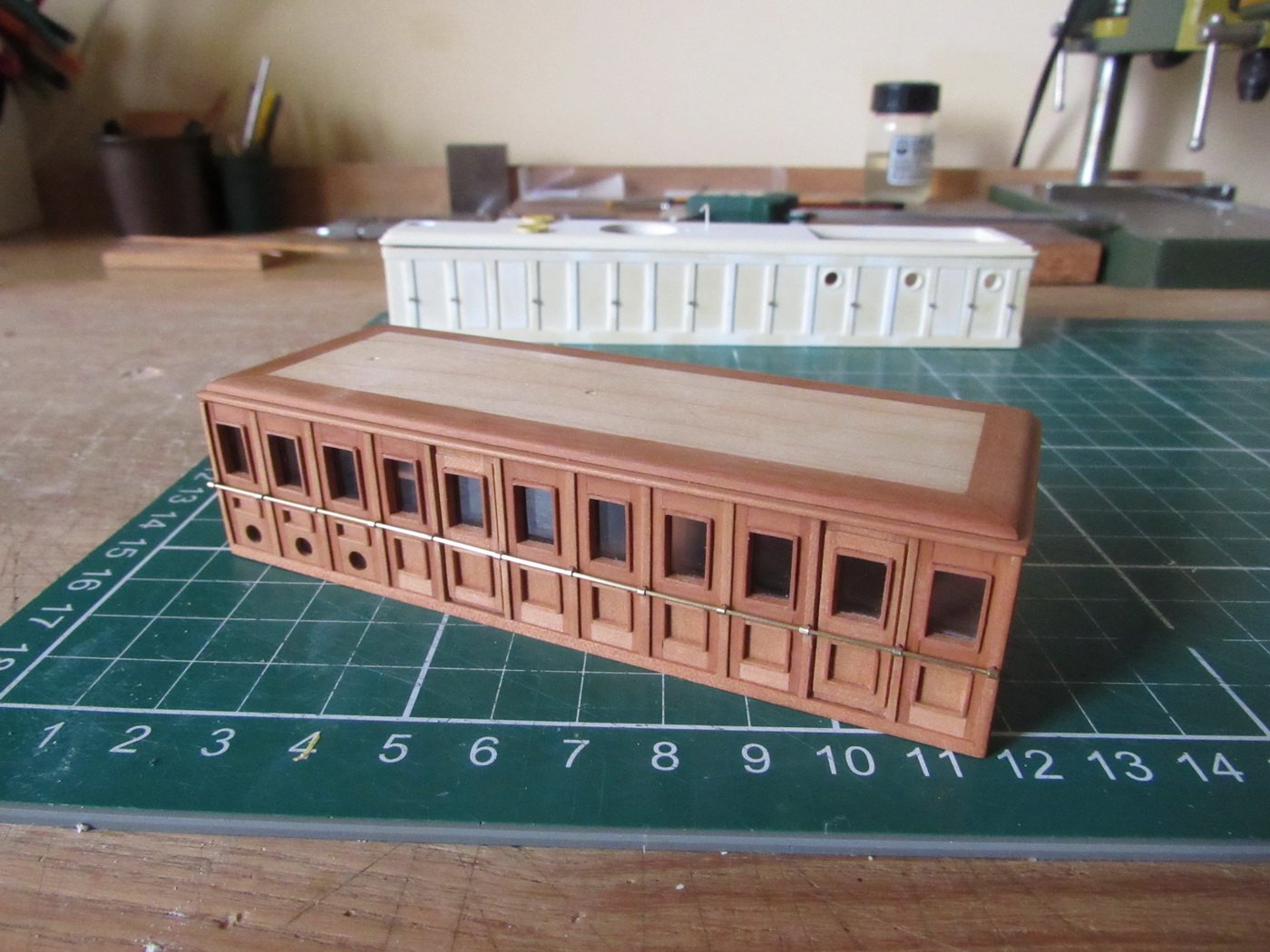
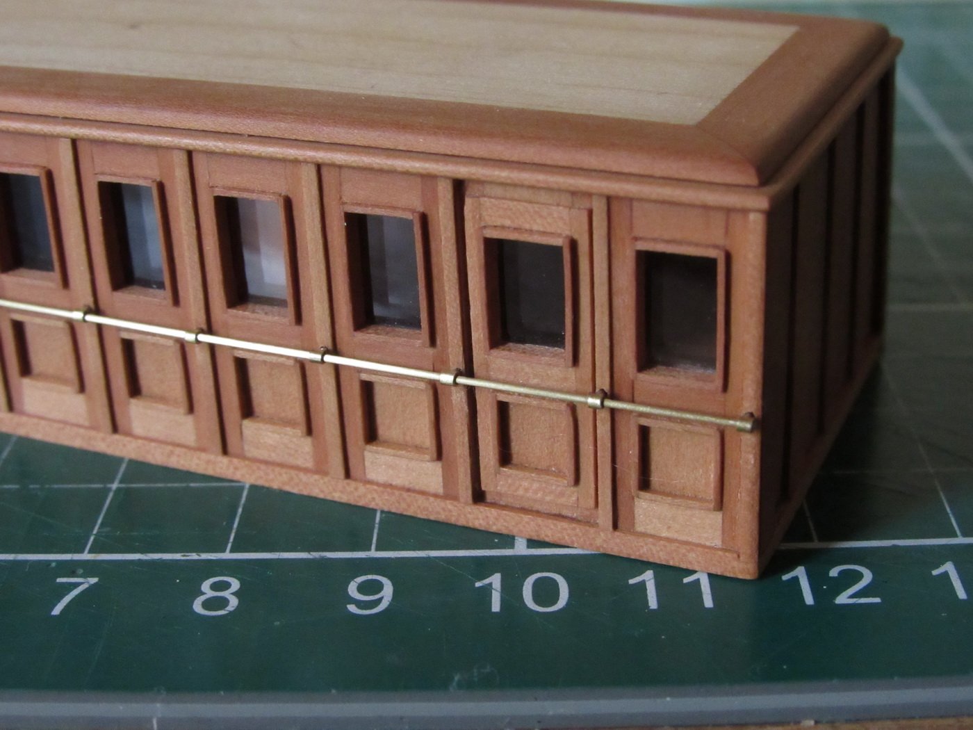
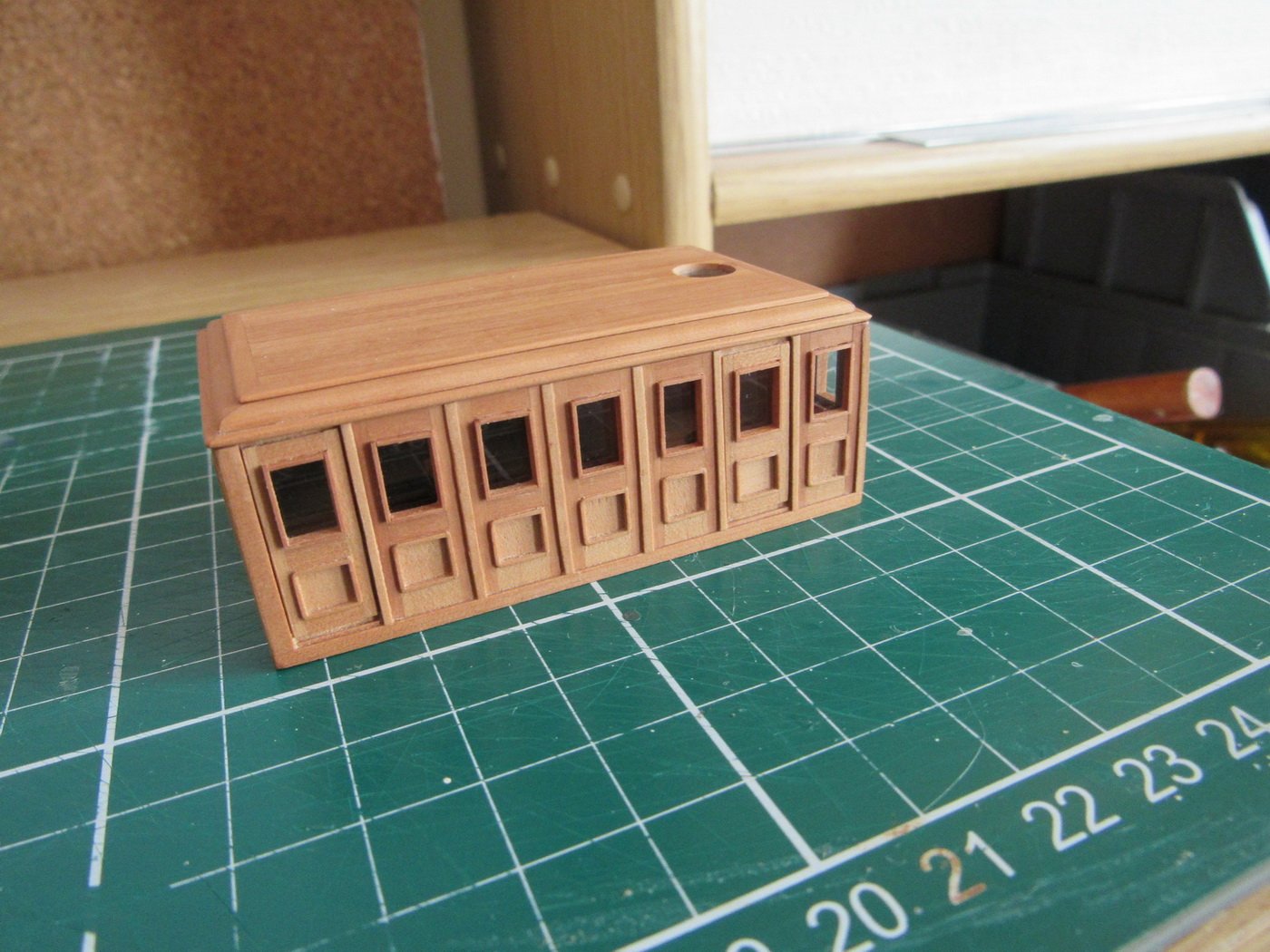
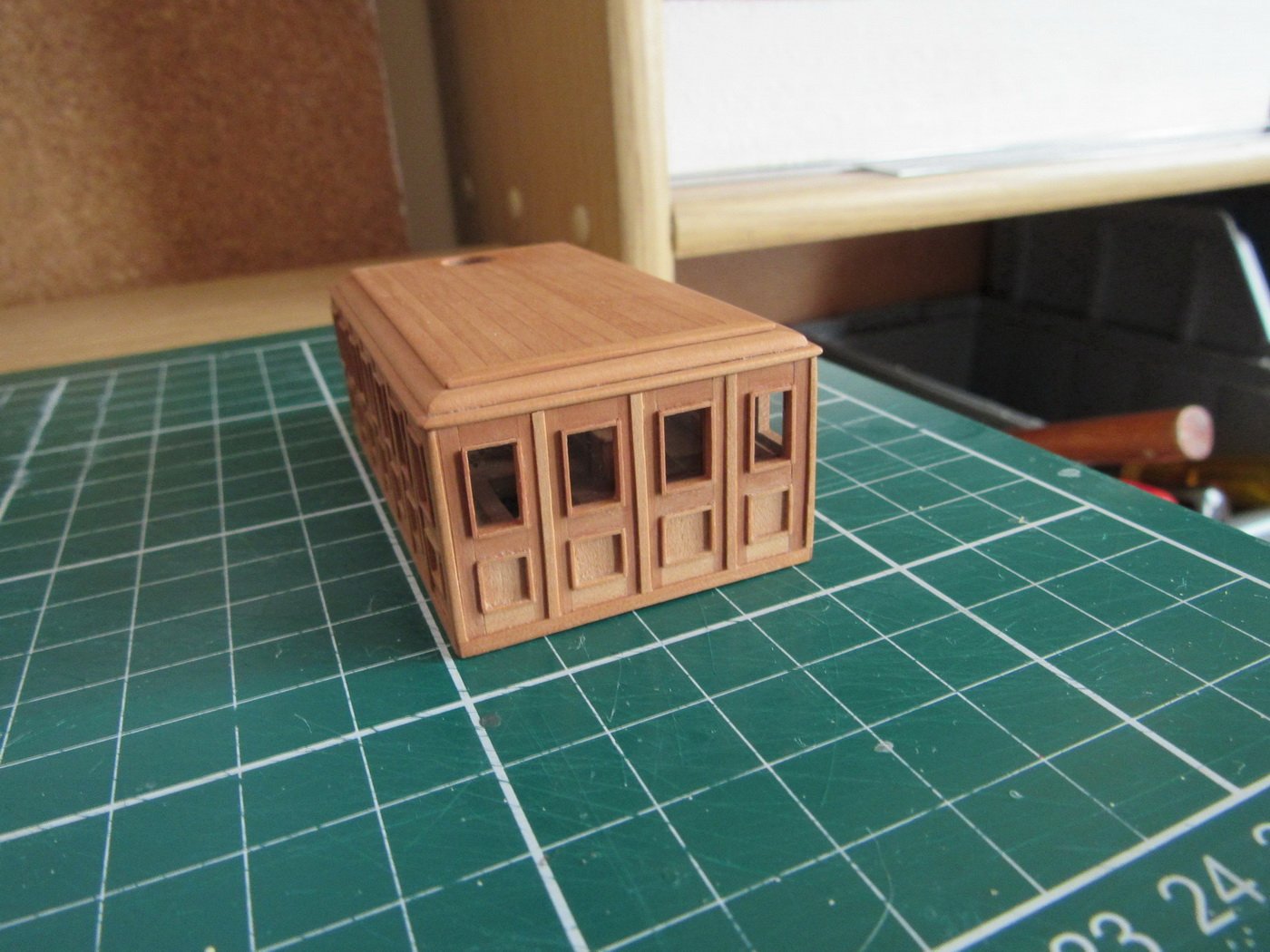
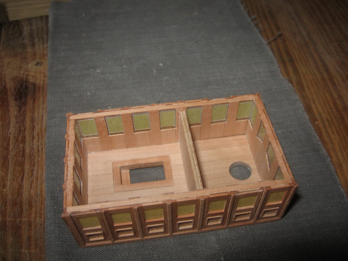
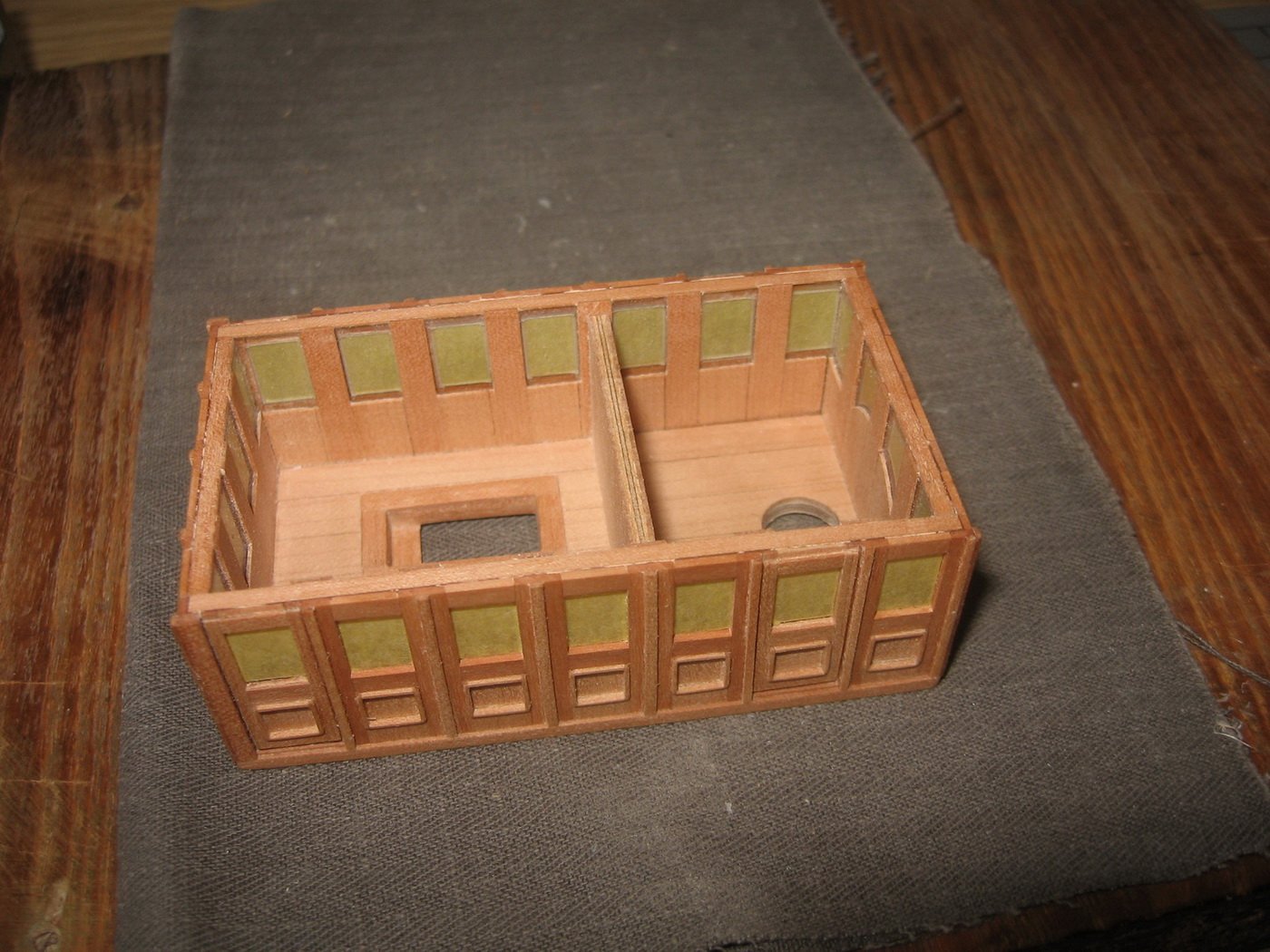
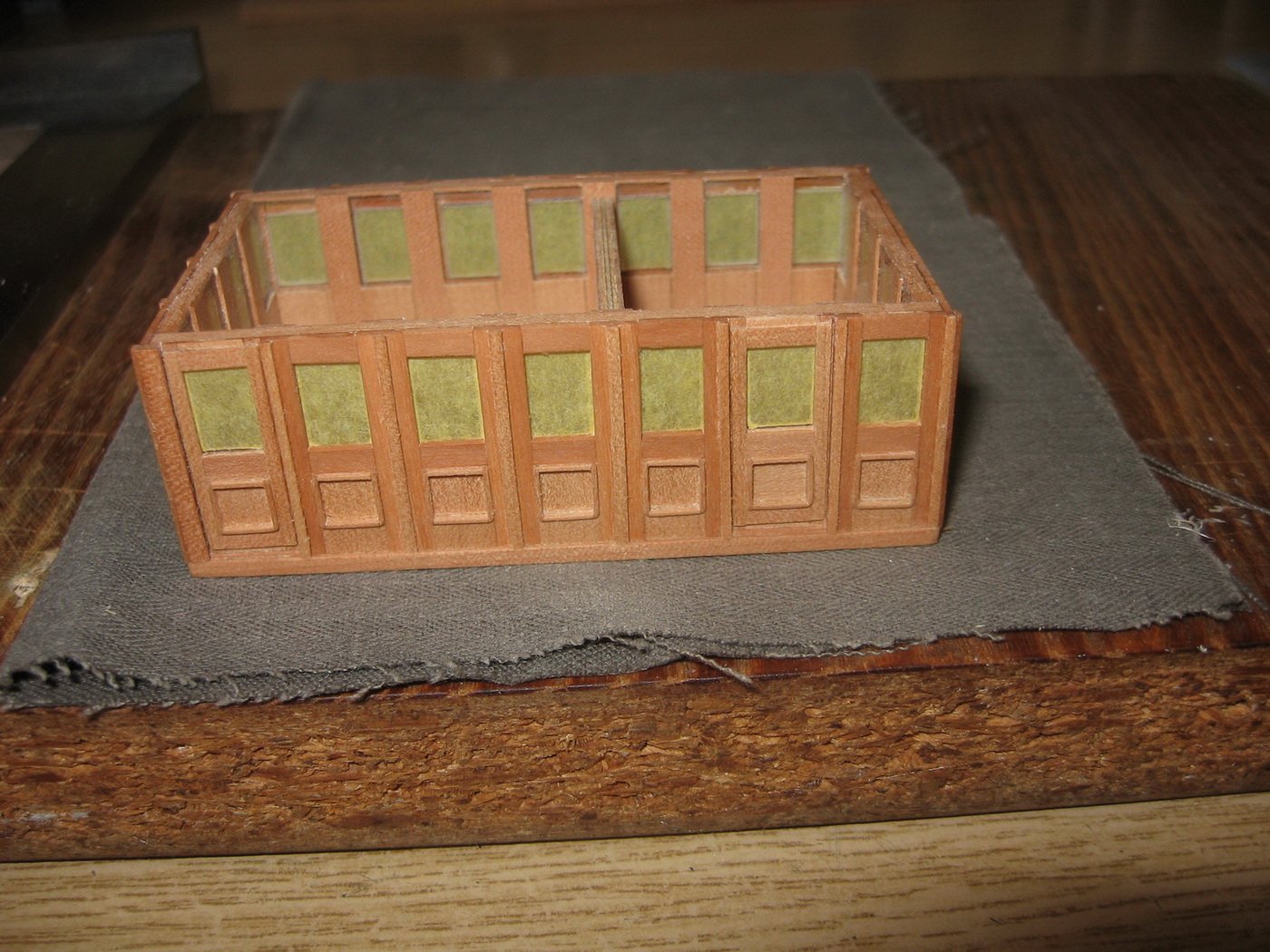
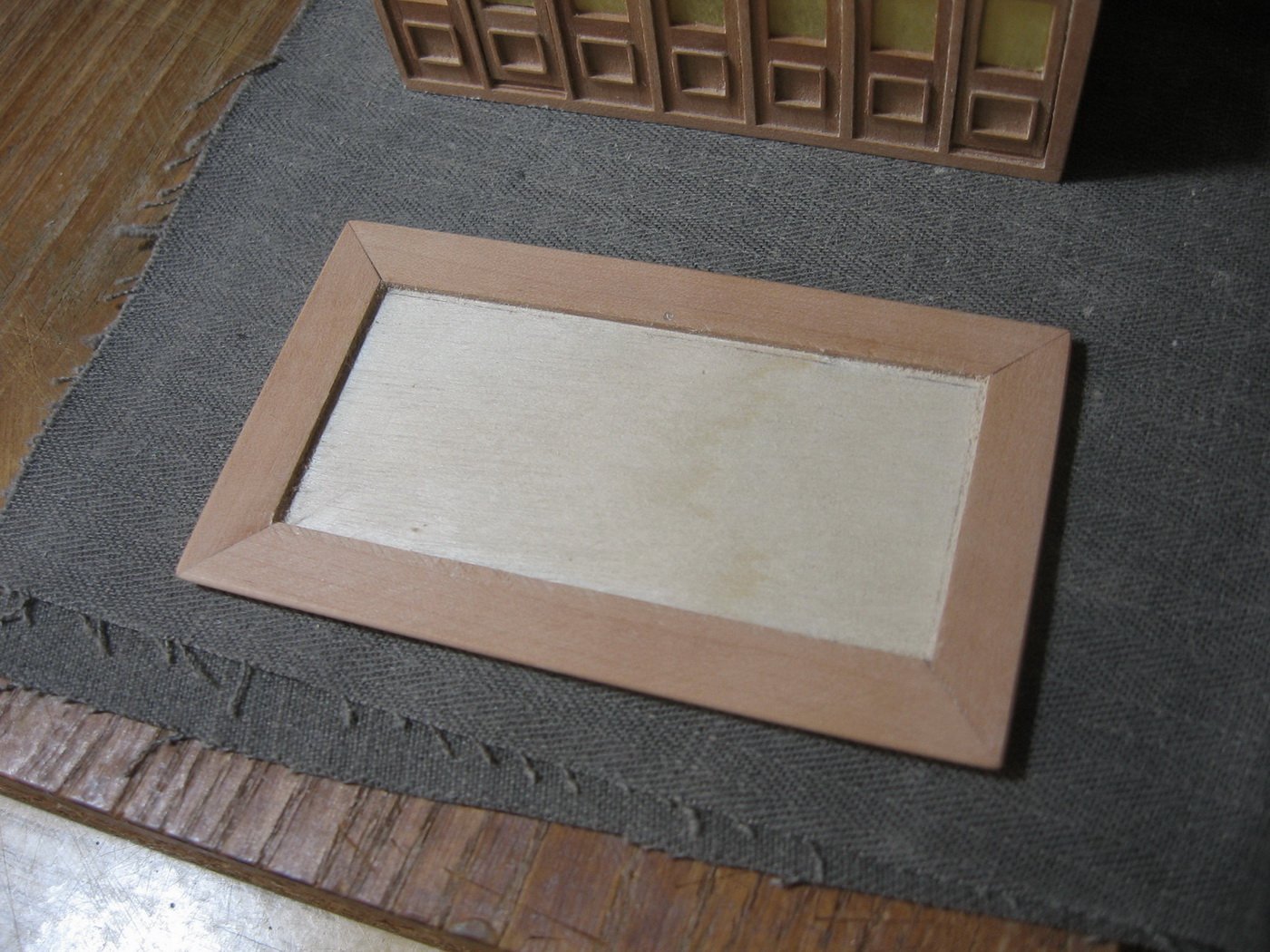
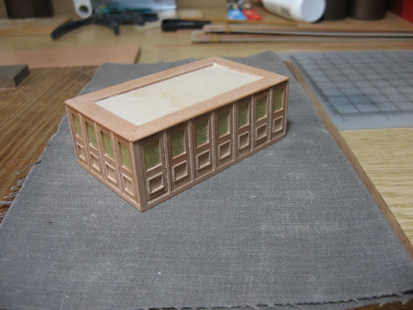
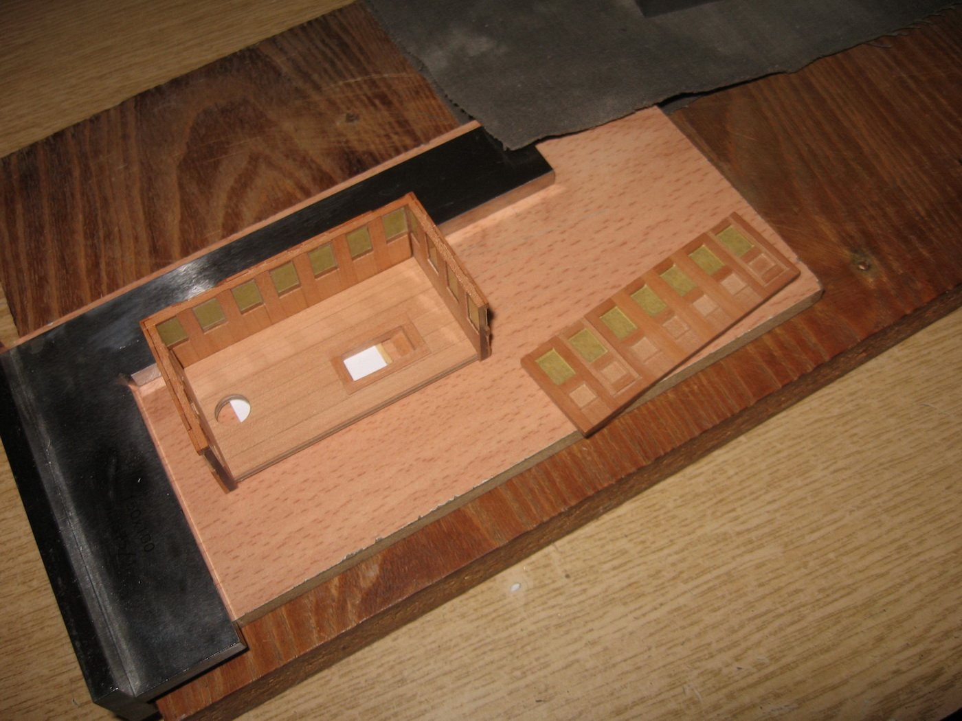
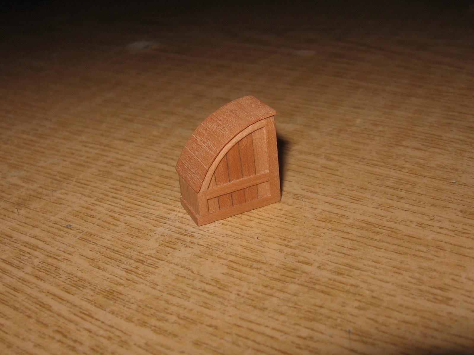
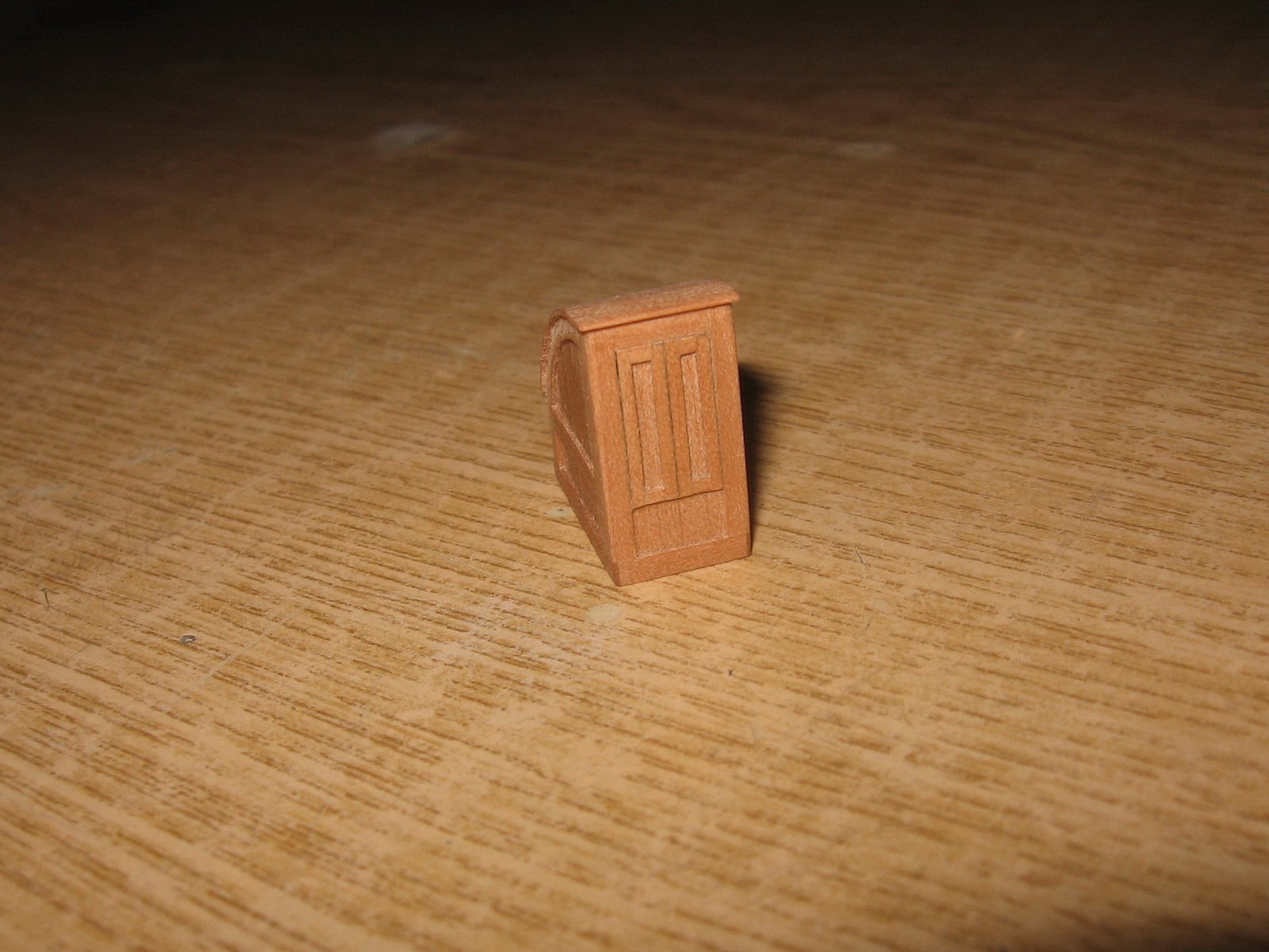
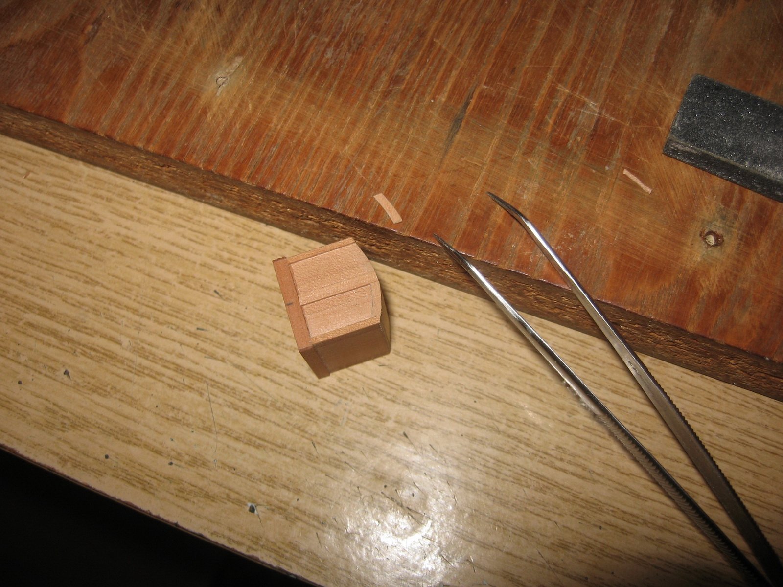
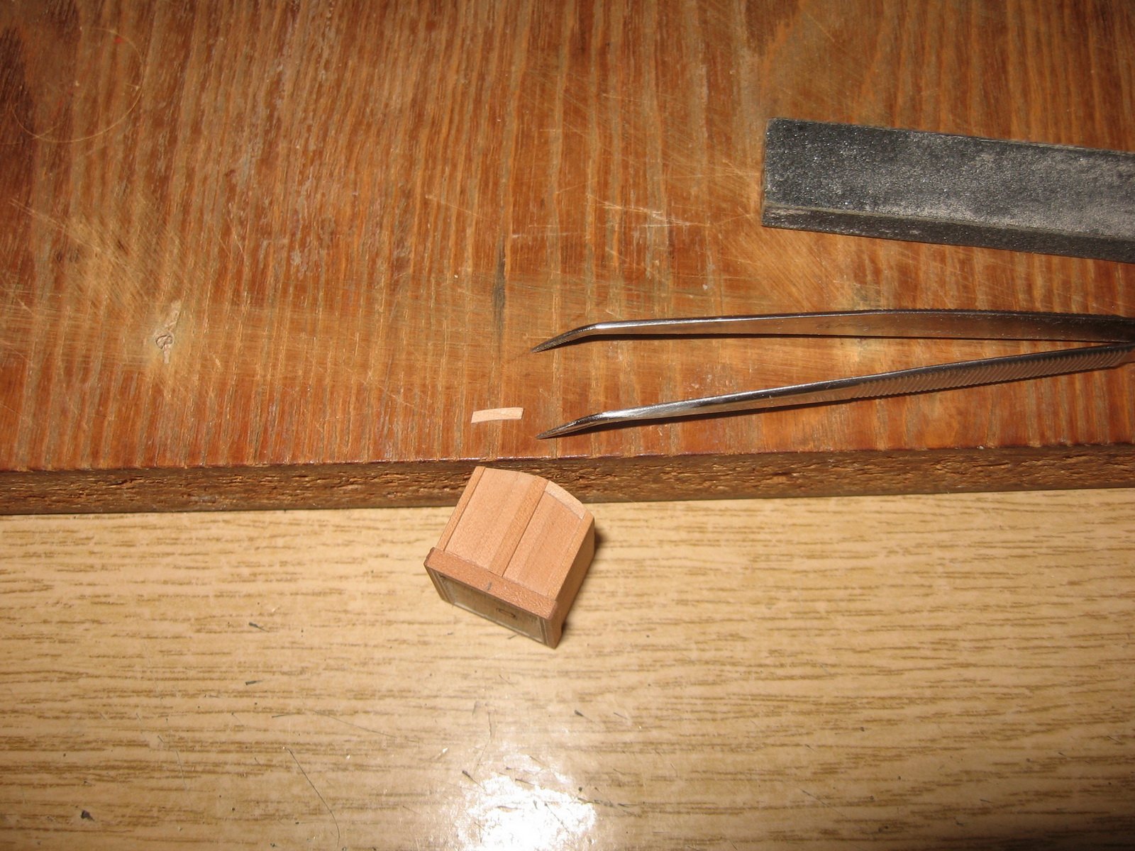
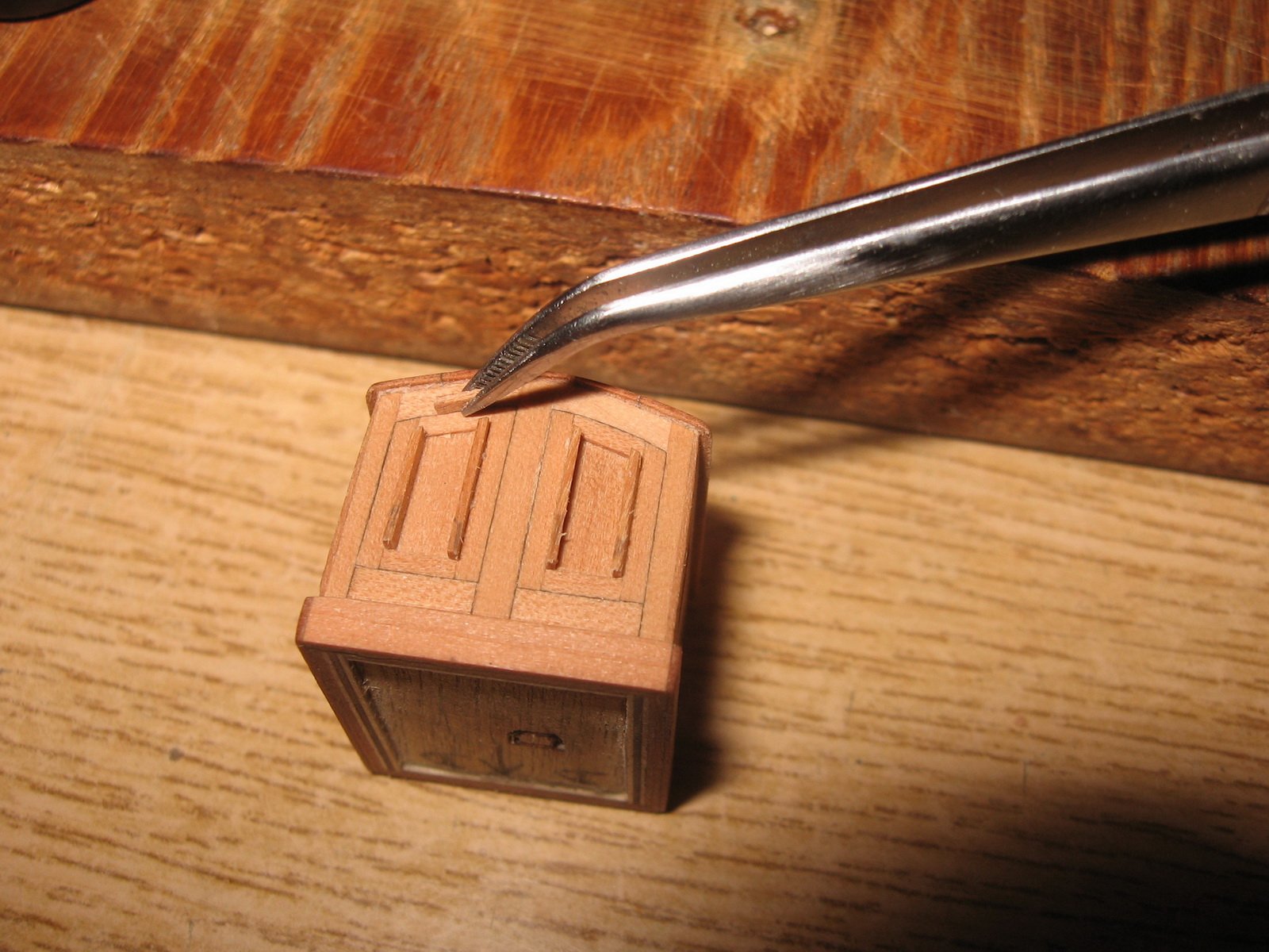
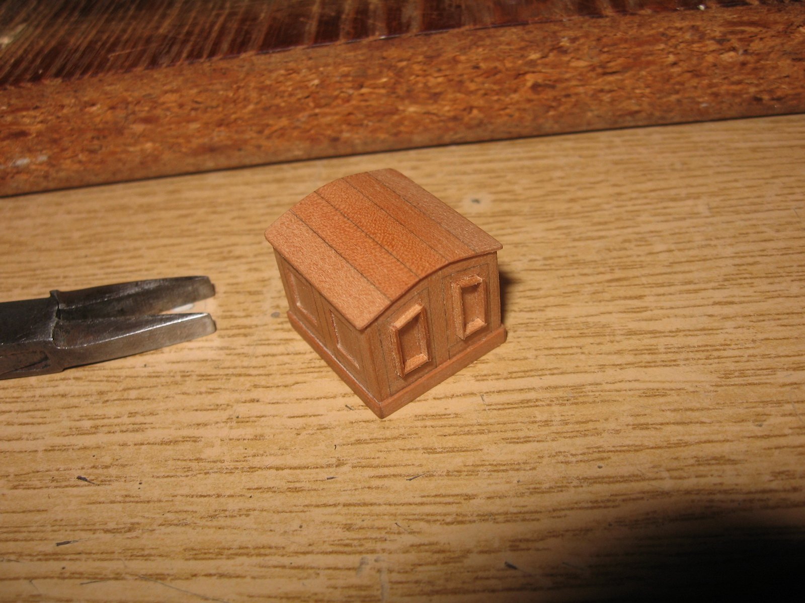
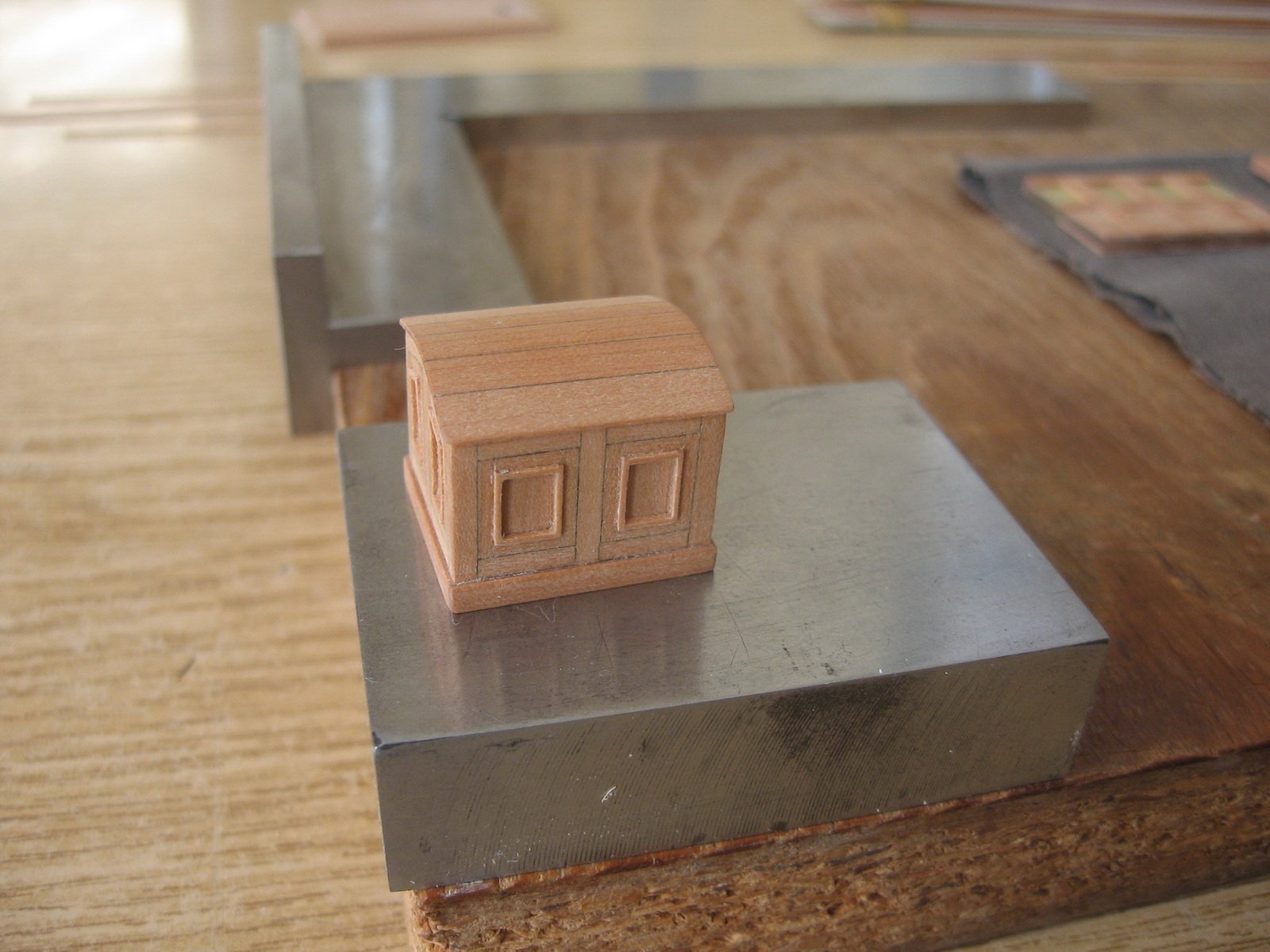
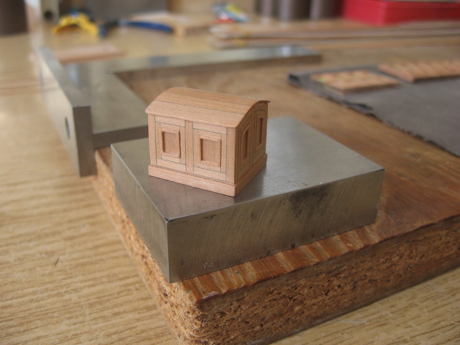
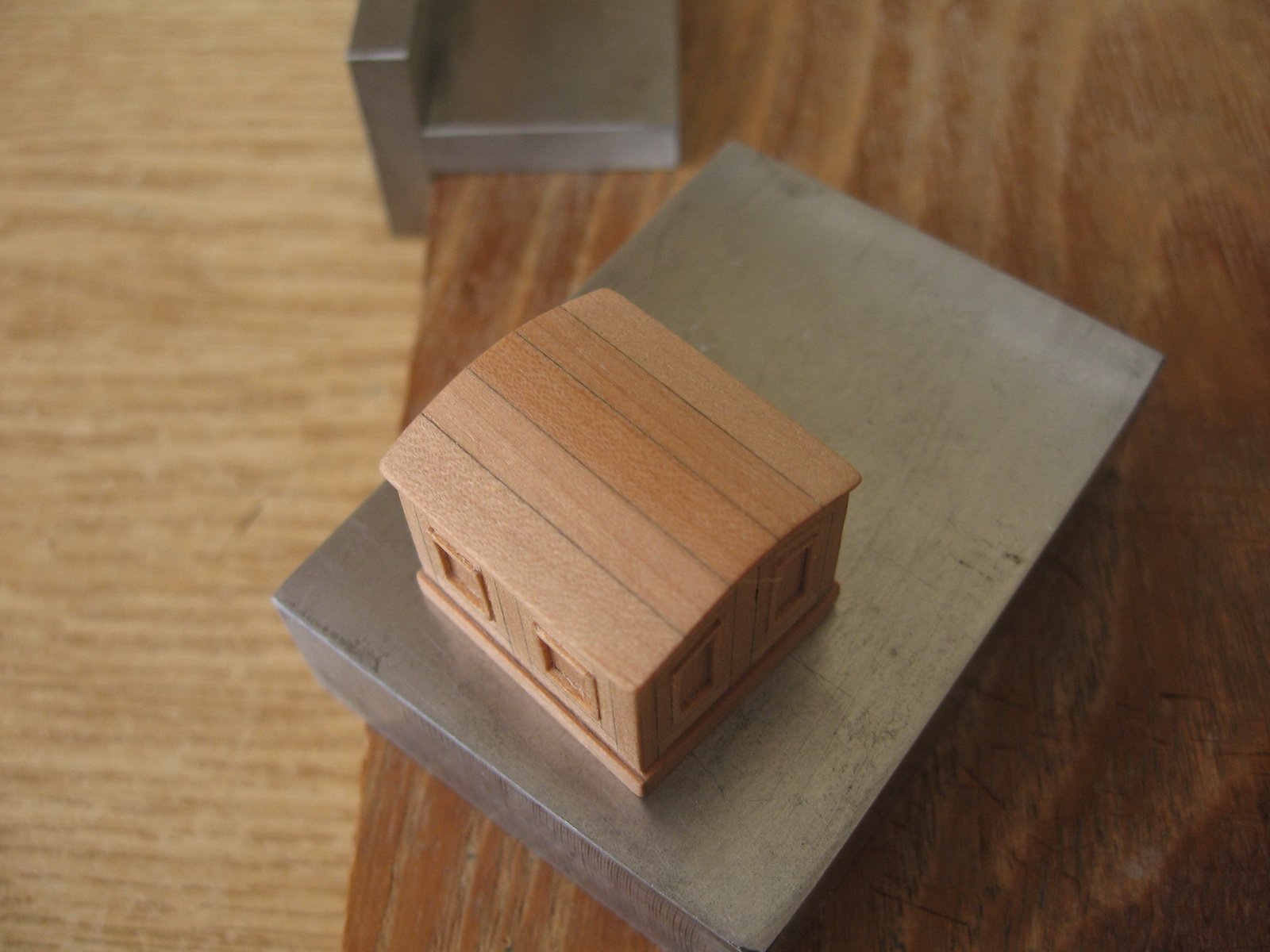
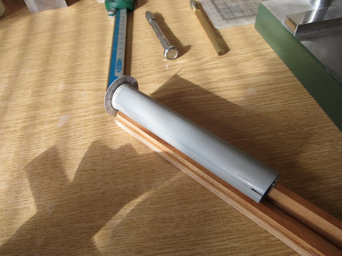
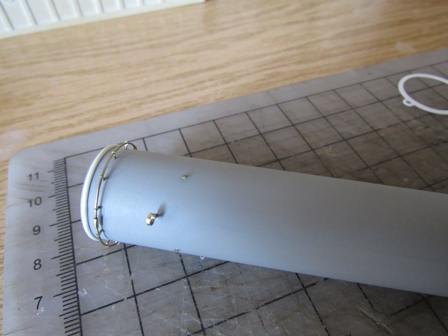
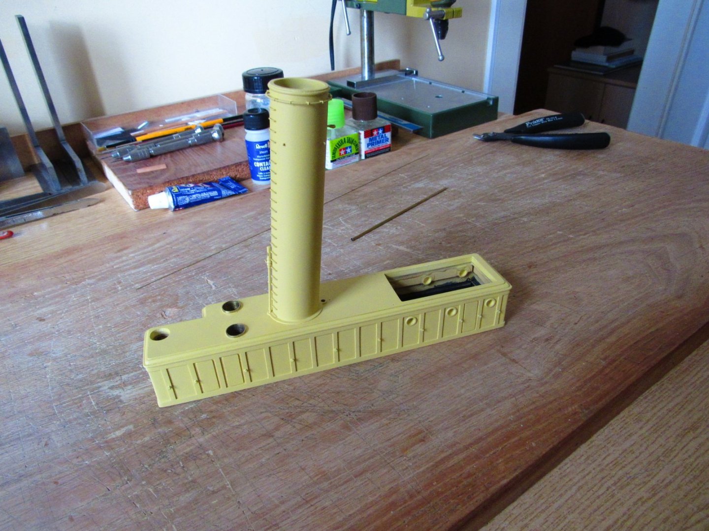
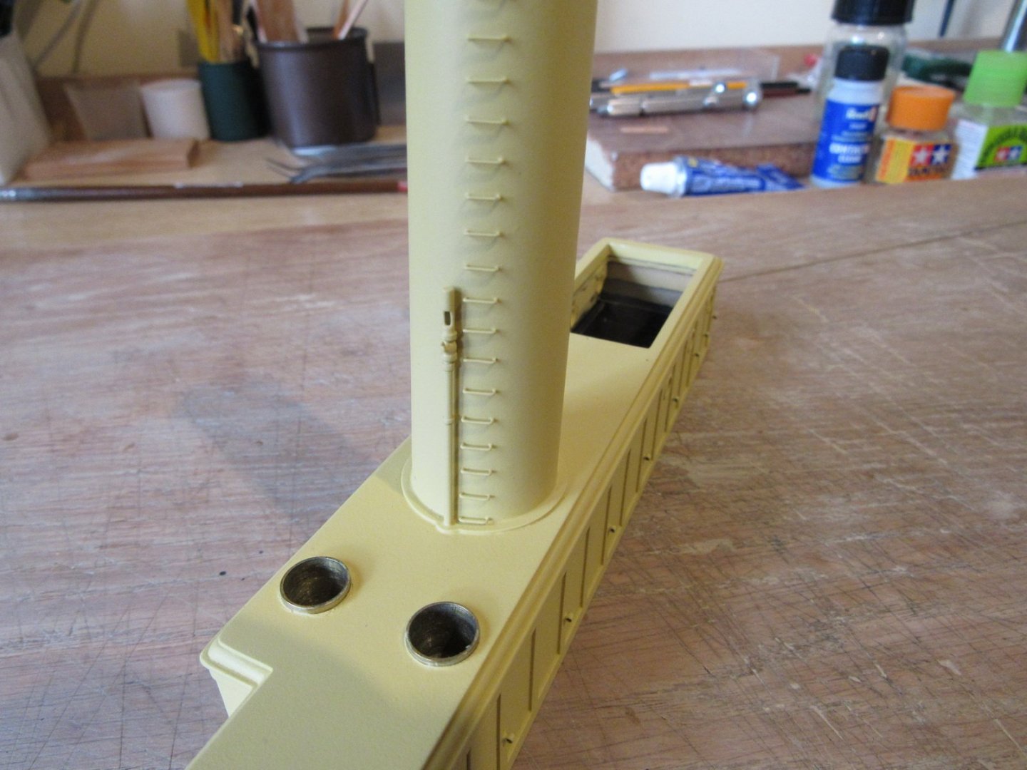
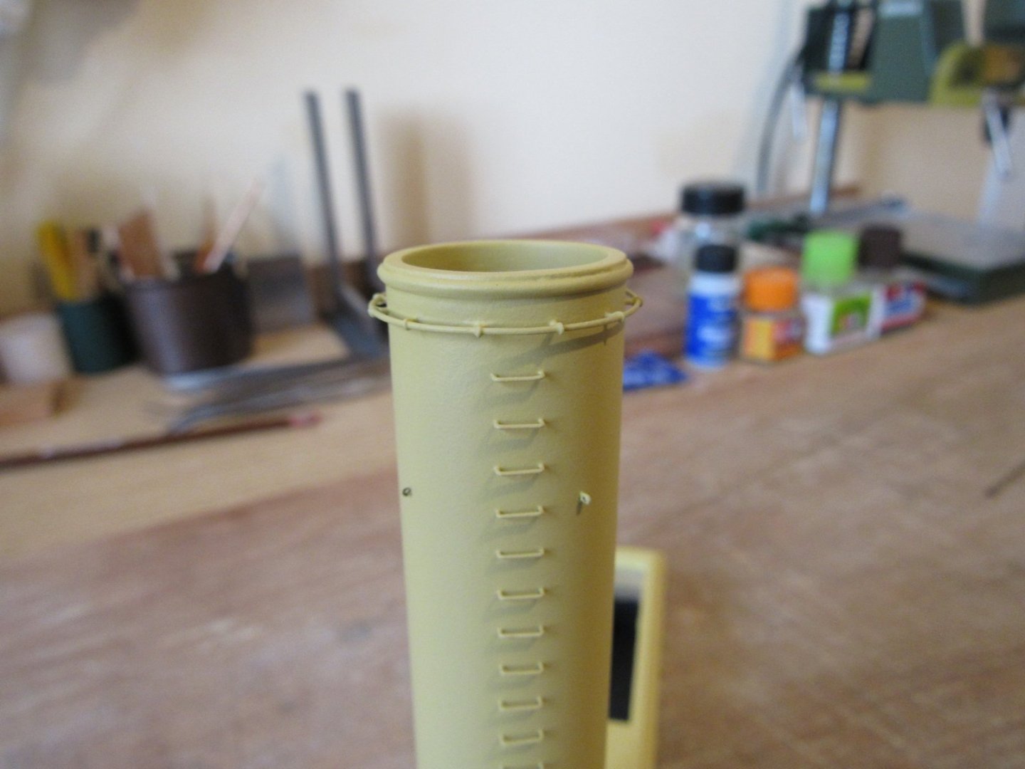
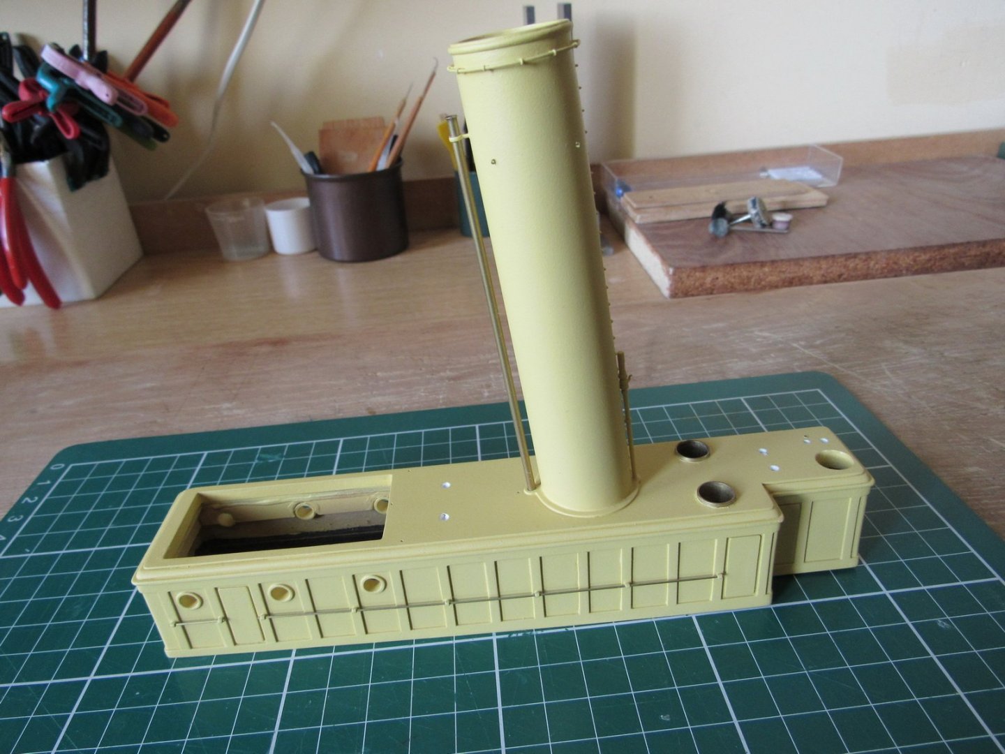
Engine room house and funnel. Trying to build the funnel I was very lucky to find a plastic tube with exact diameter.


- 272 replies
-
- 12
-

-

-
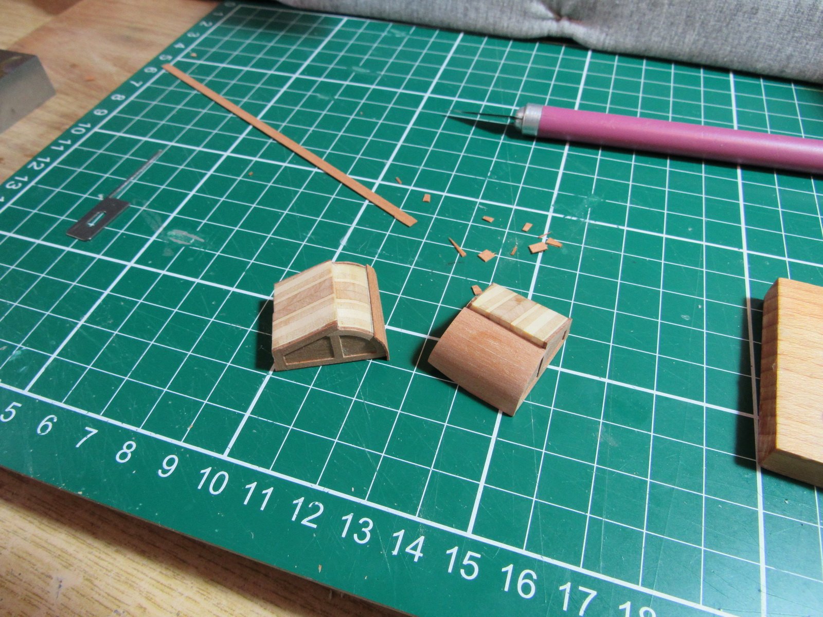
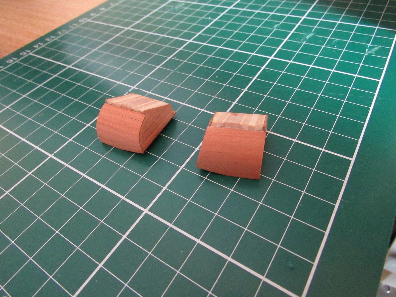
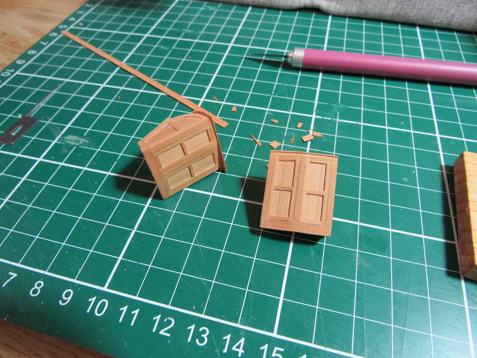
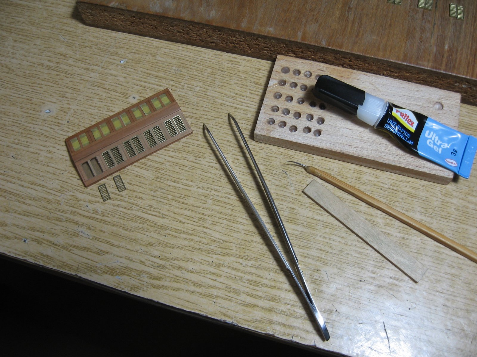
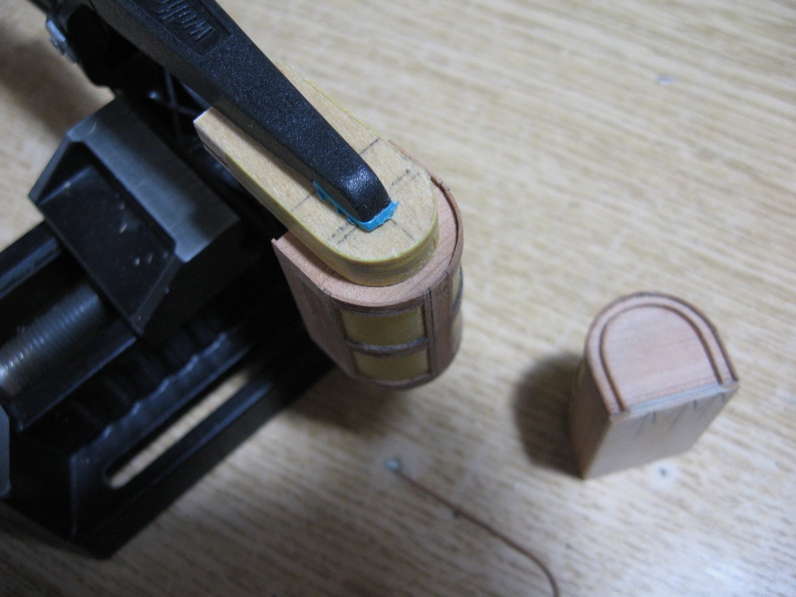
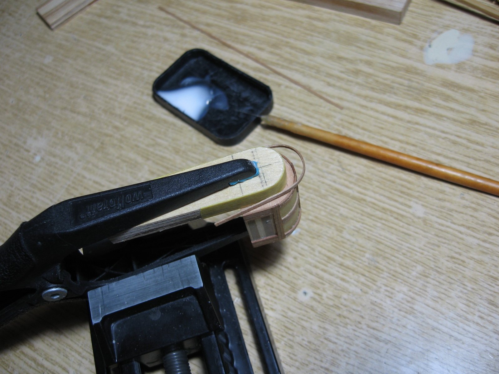
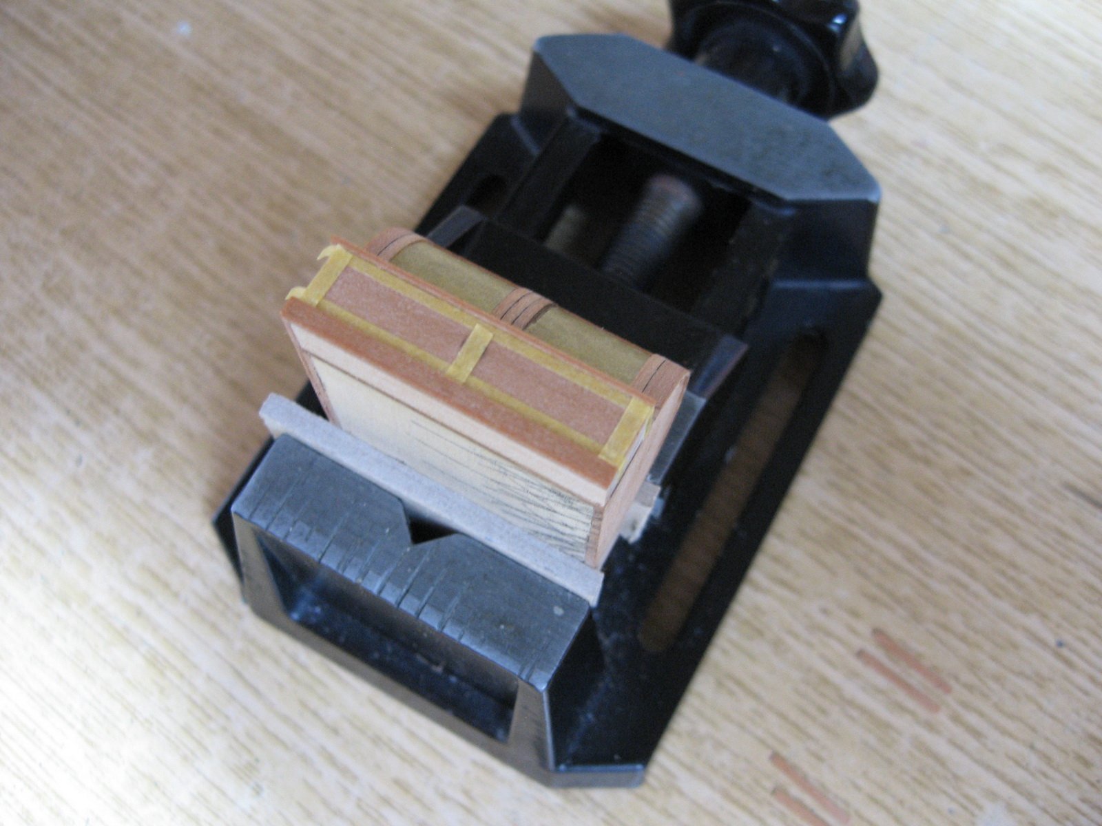
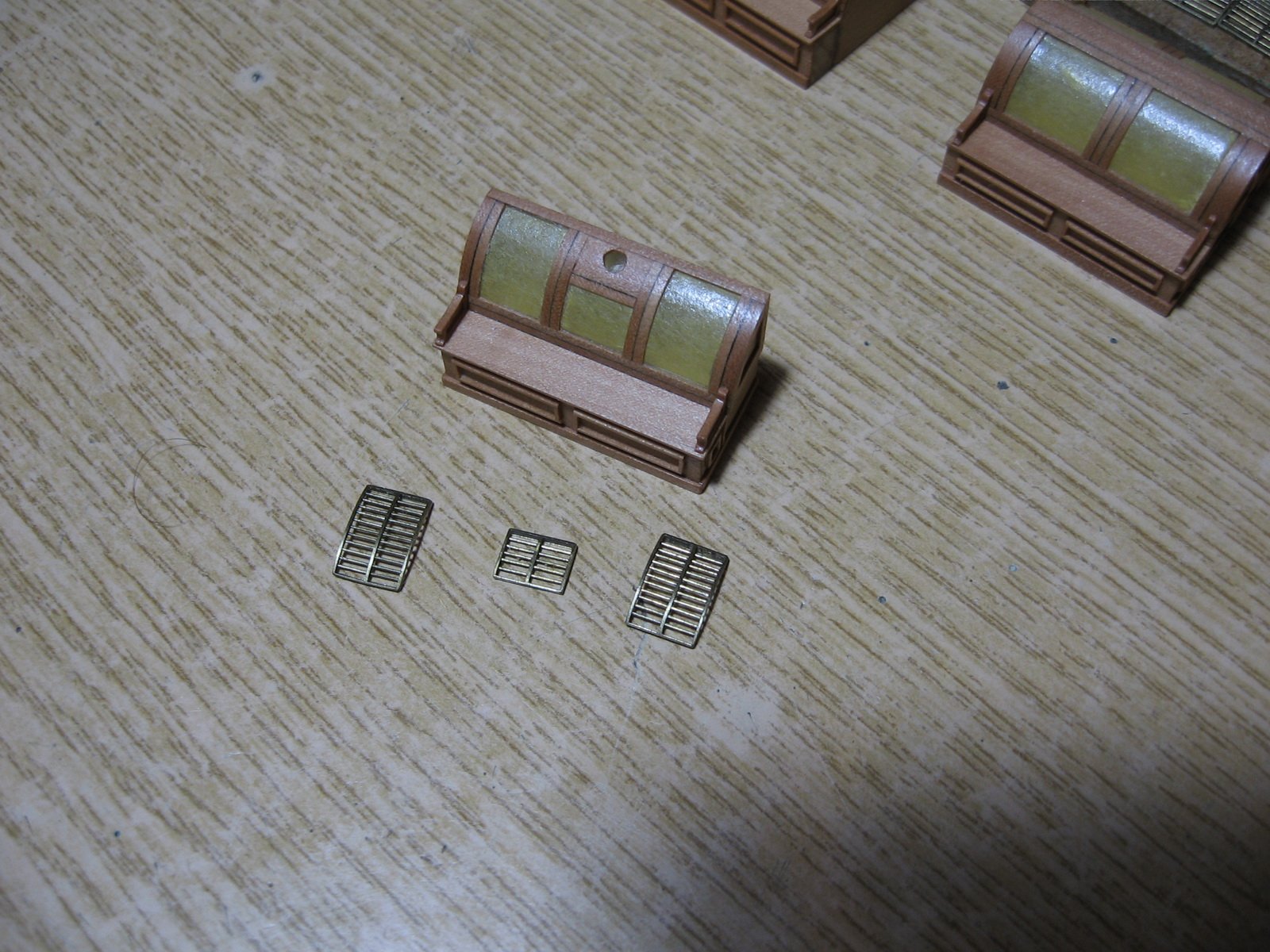
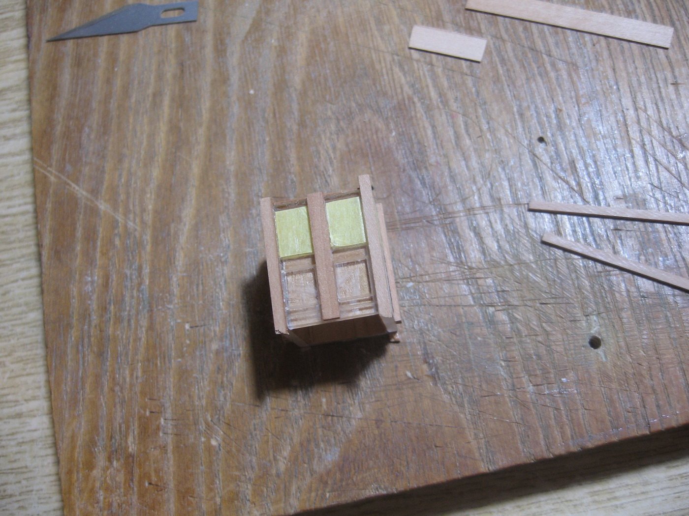
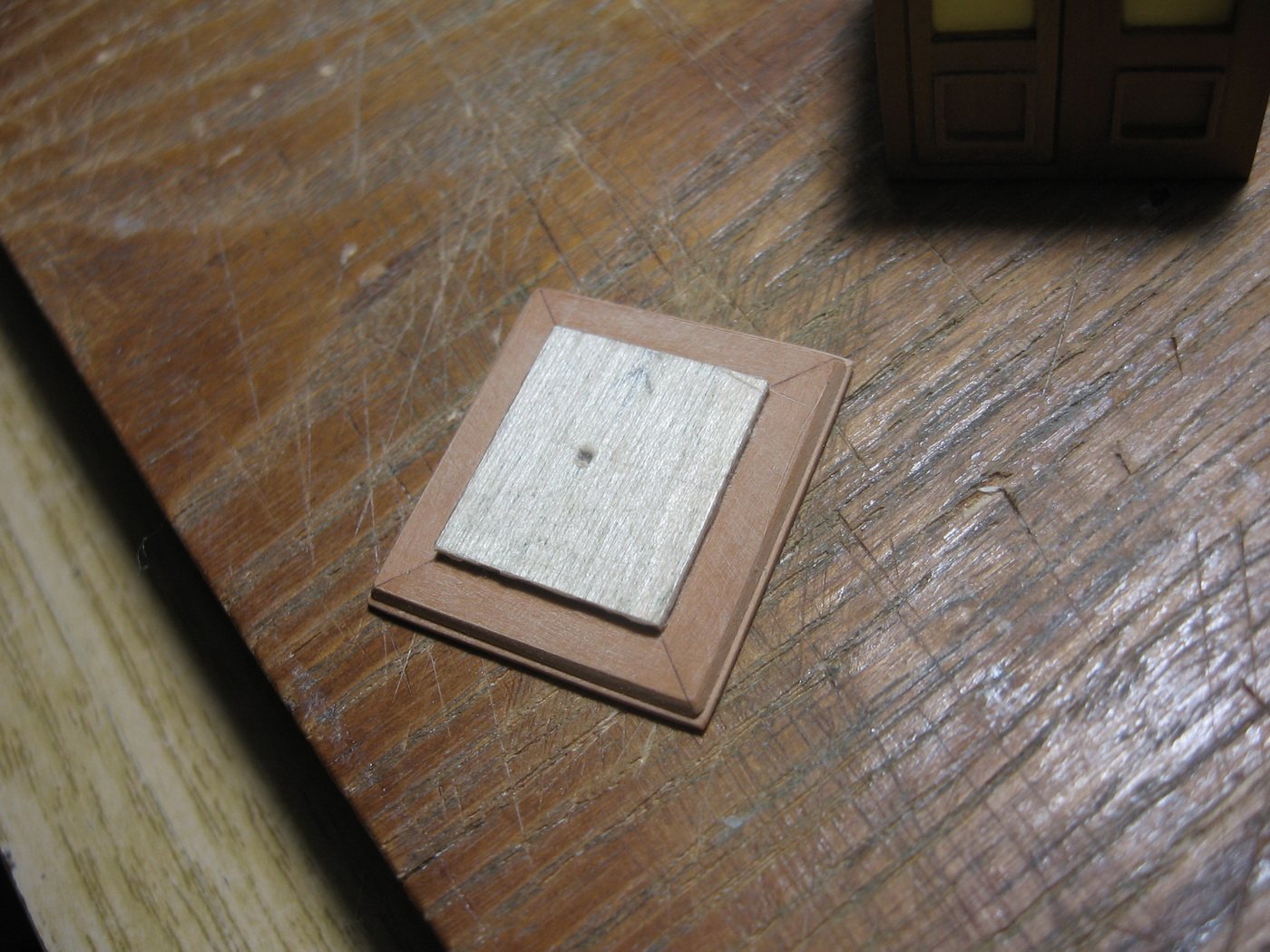
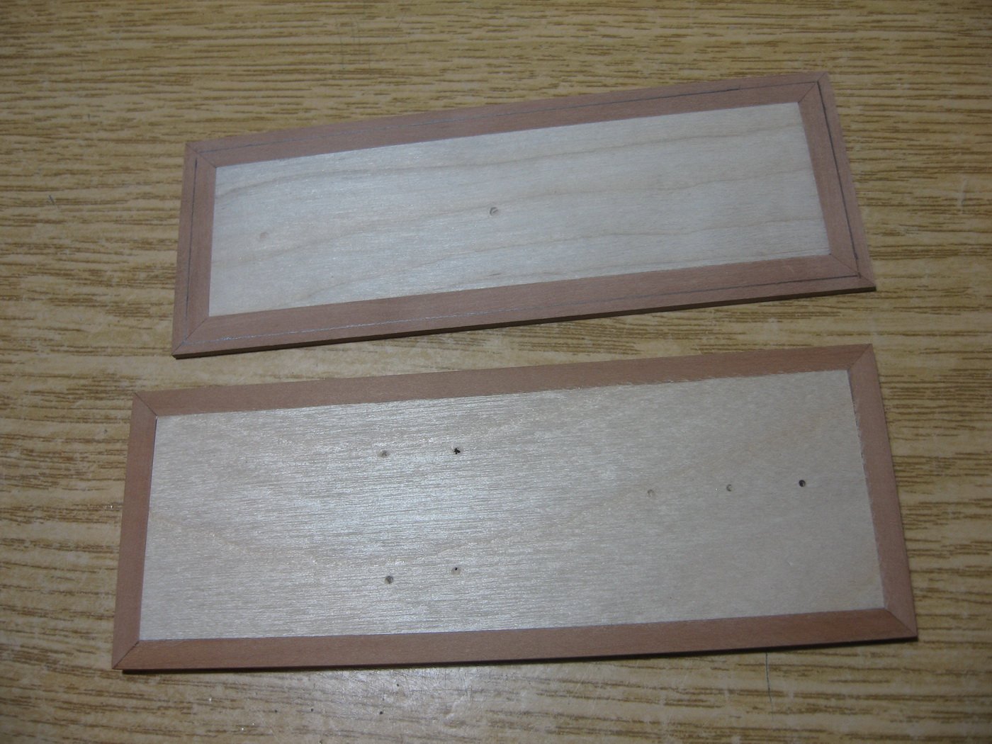
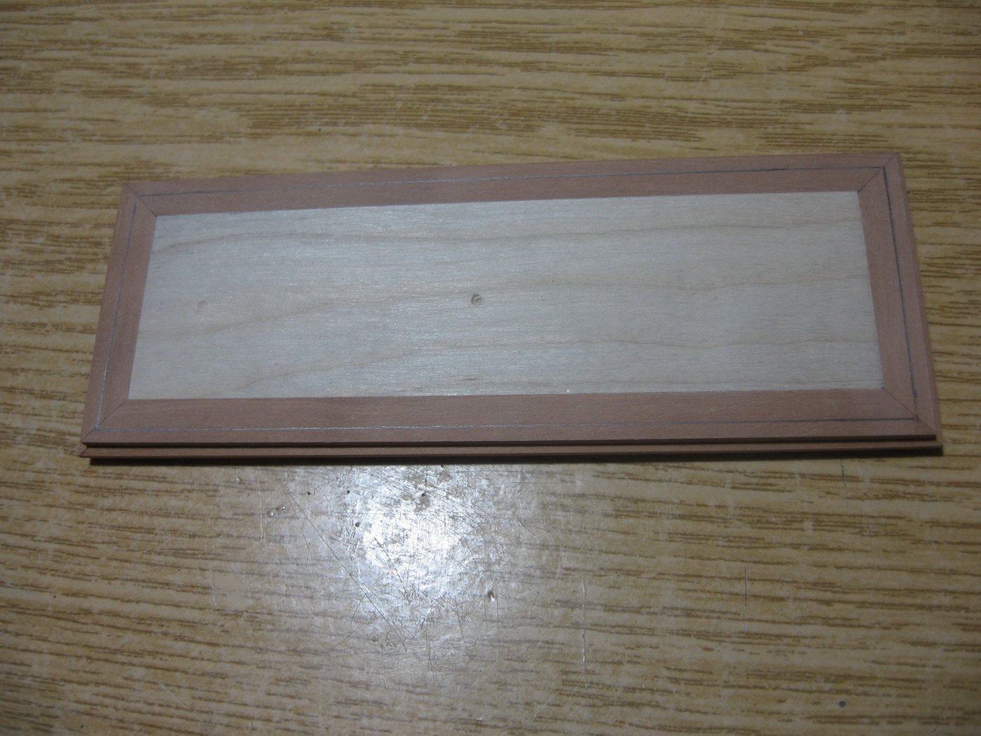
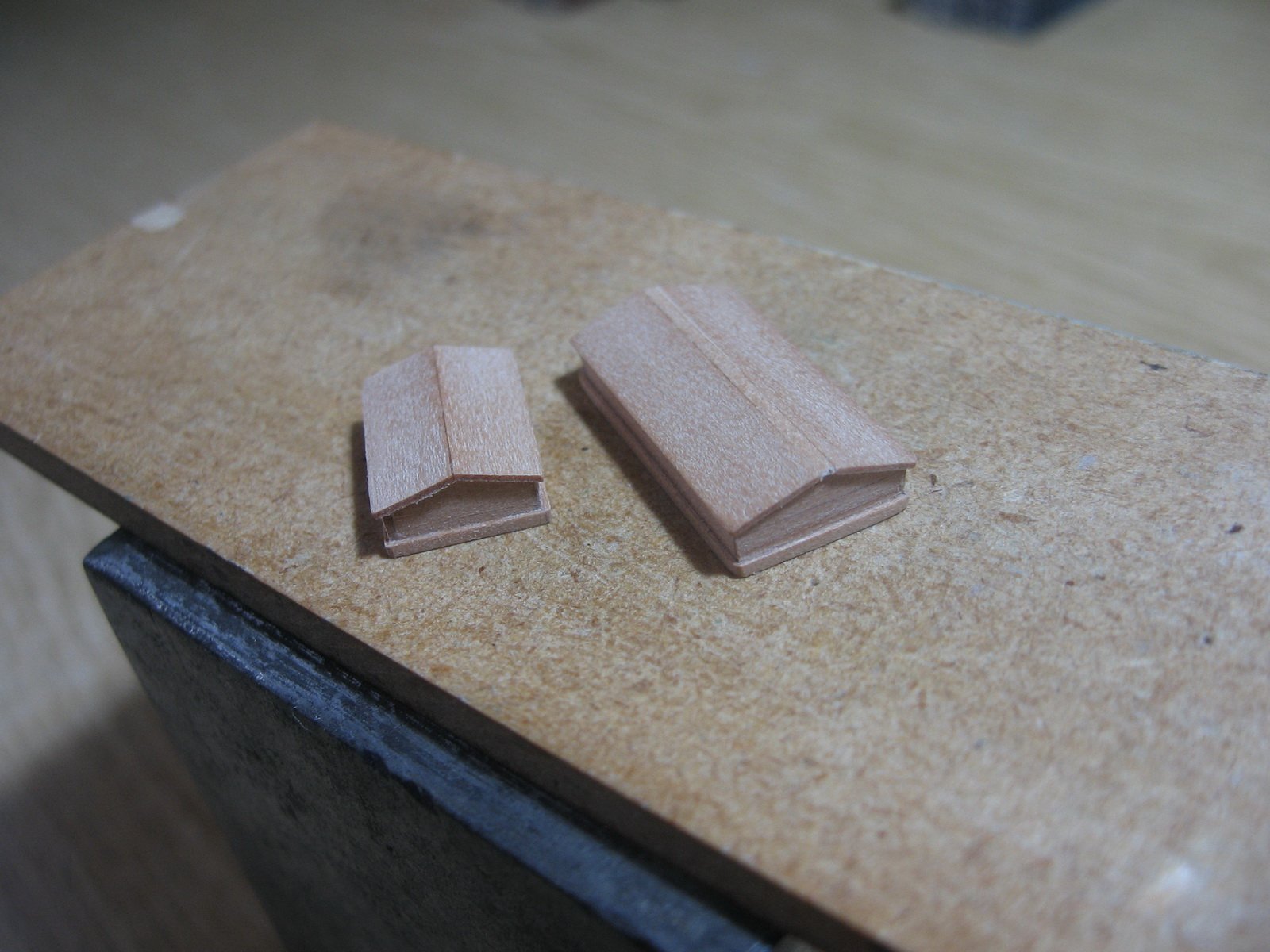
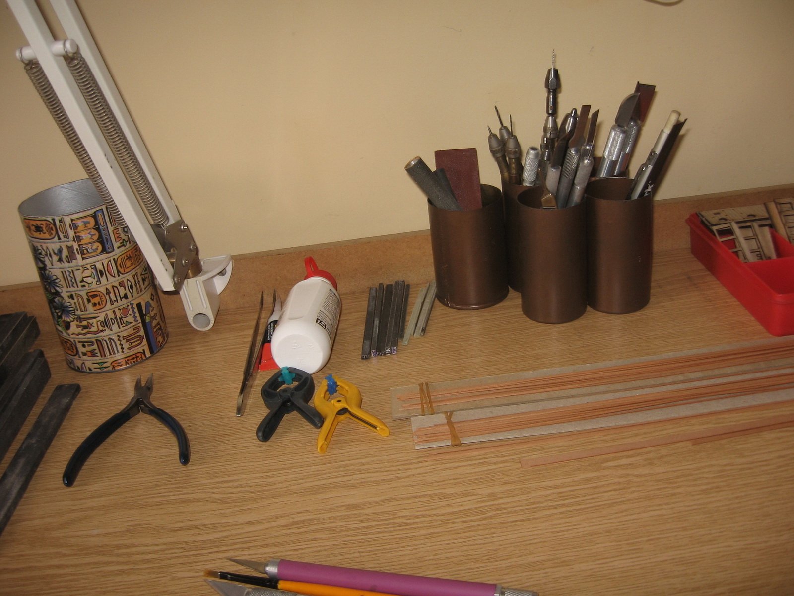
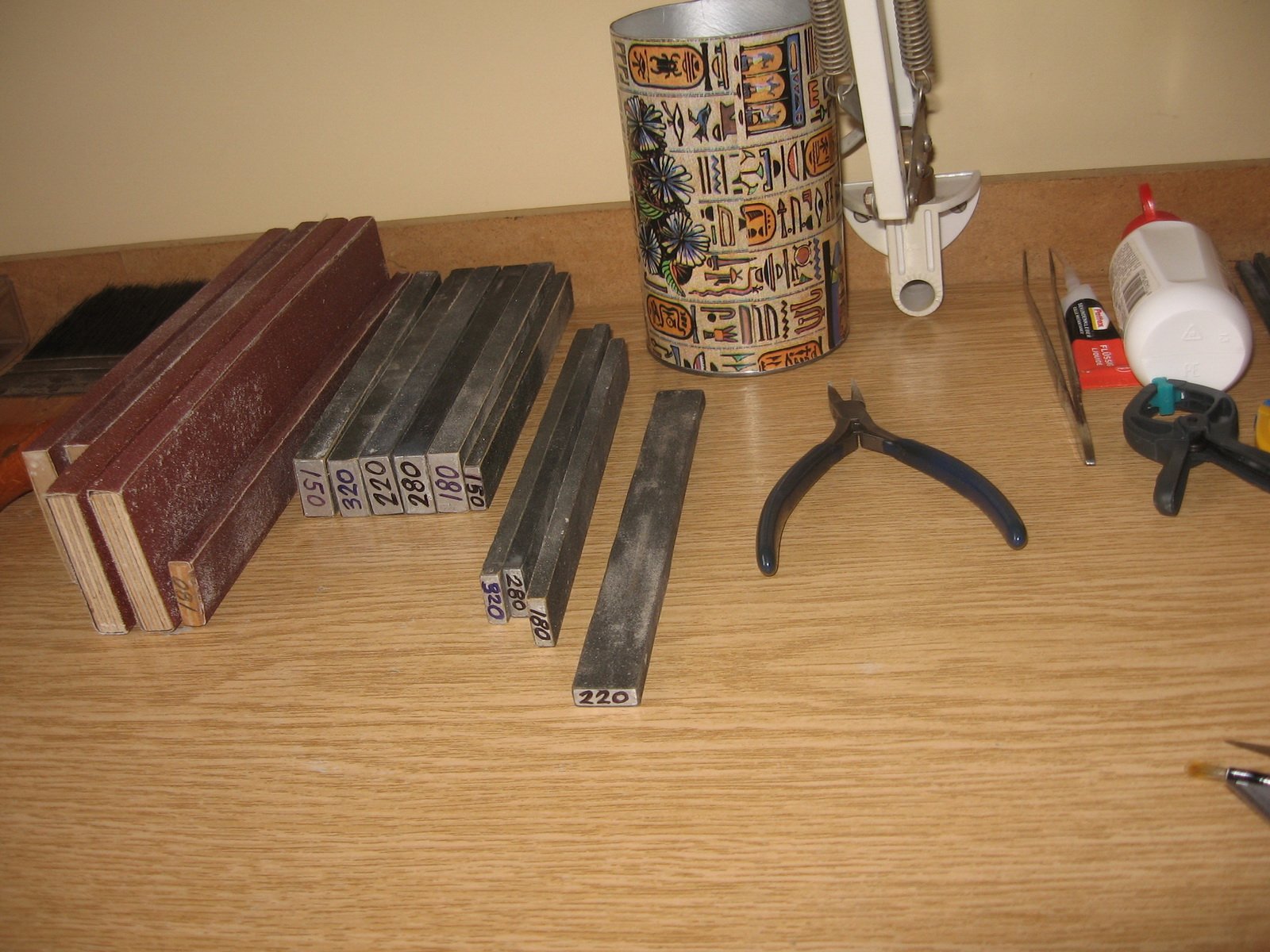
Thanks Keith, I used rapid epoxy glue for the roof parts (not for the plastic to plastic) and CA Gel for the side panels.
-
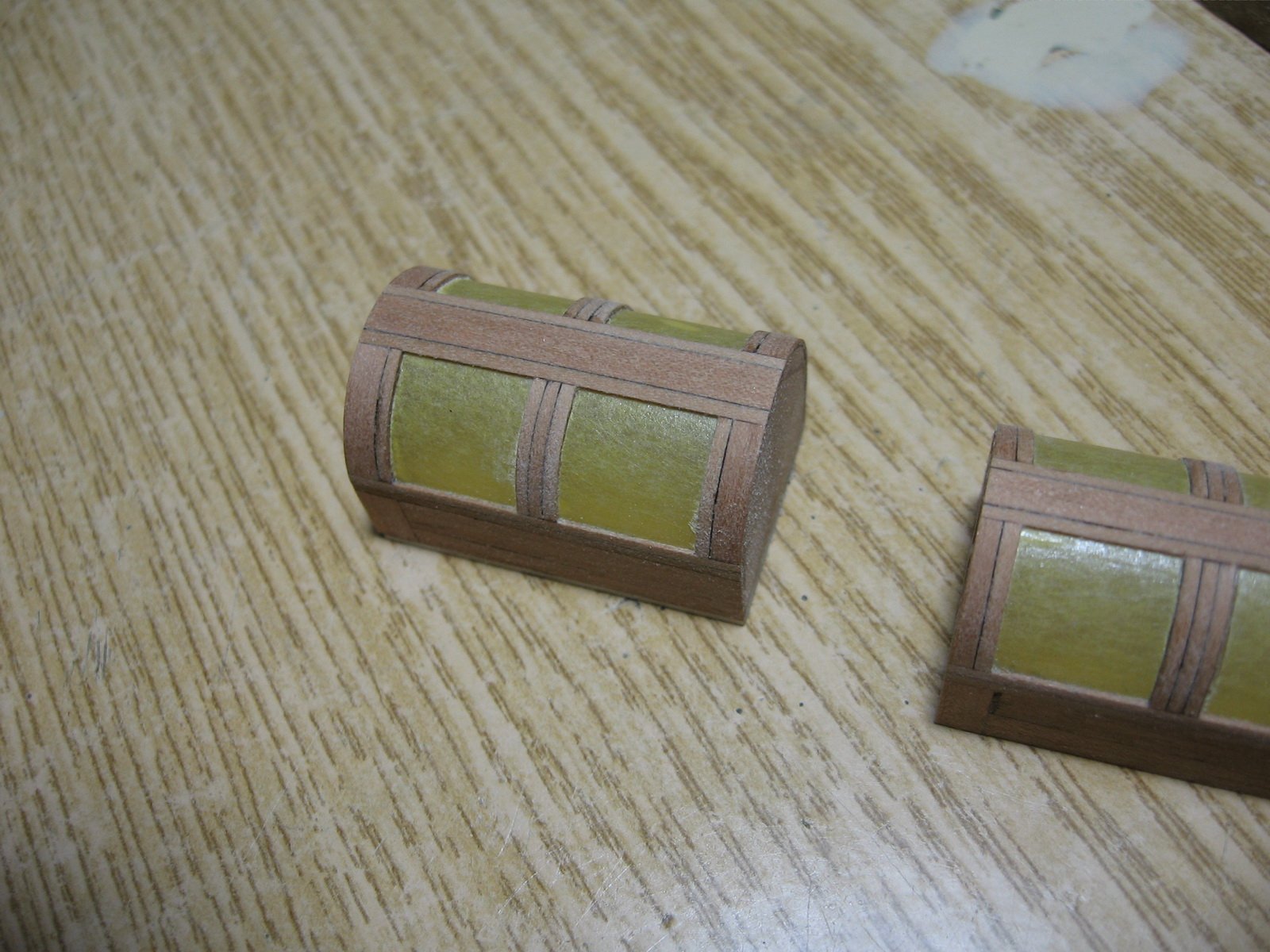
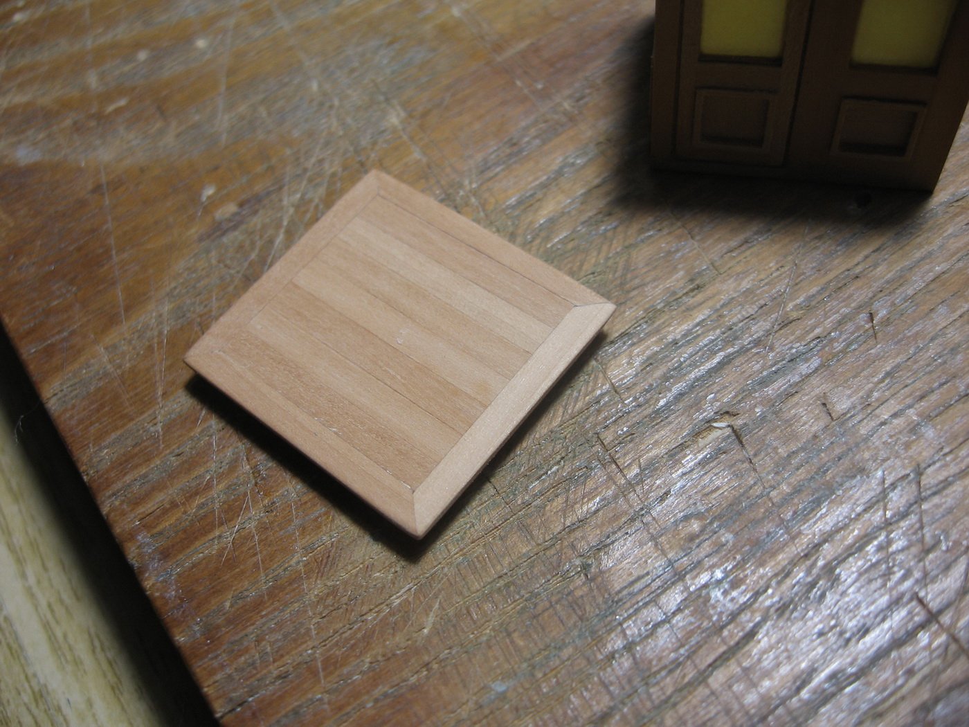
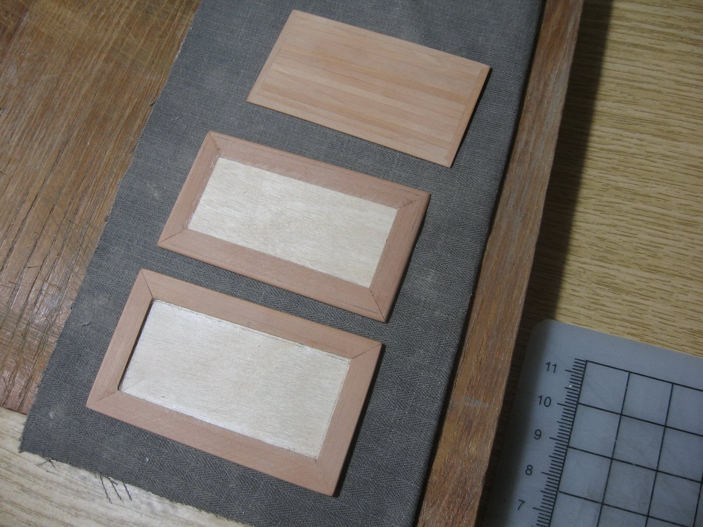
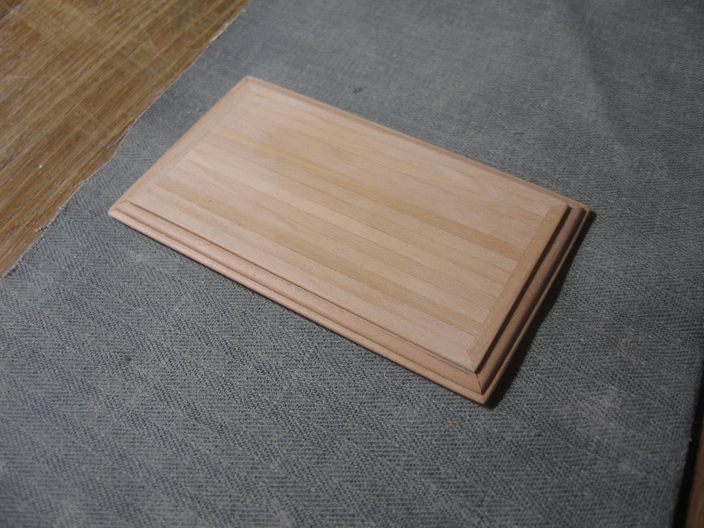
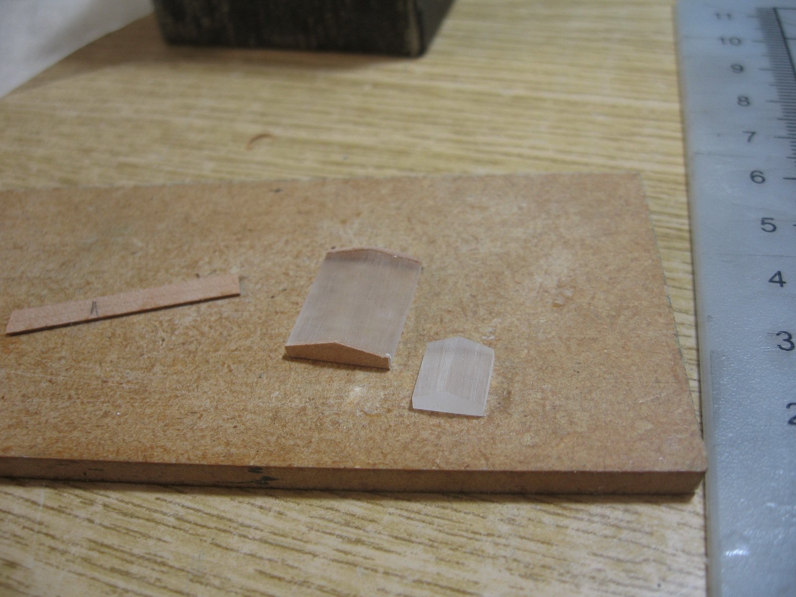
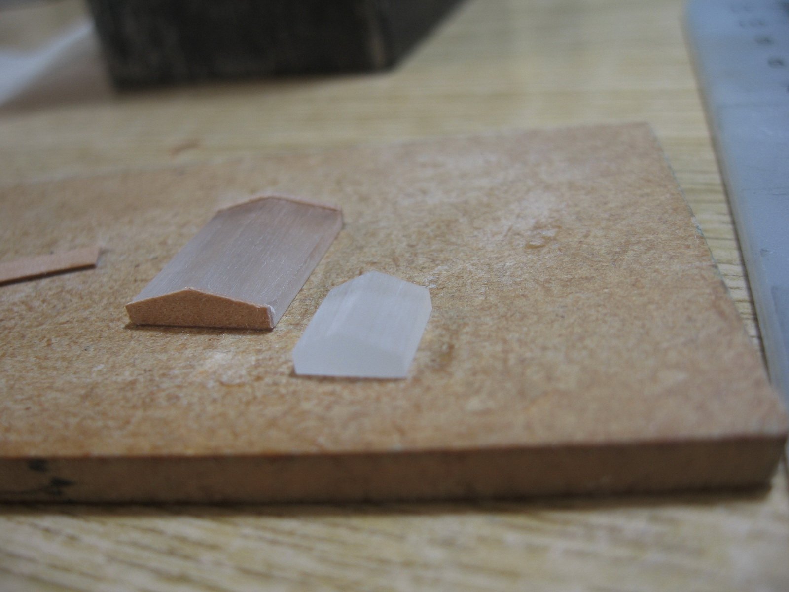
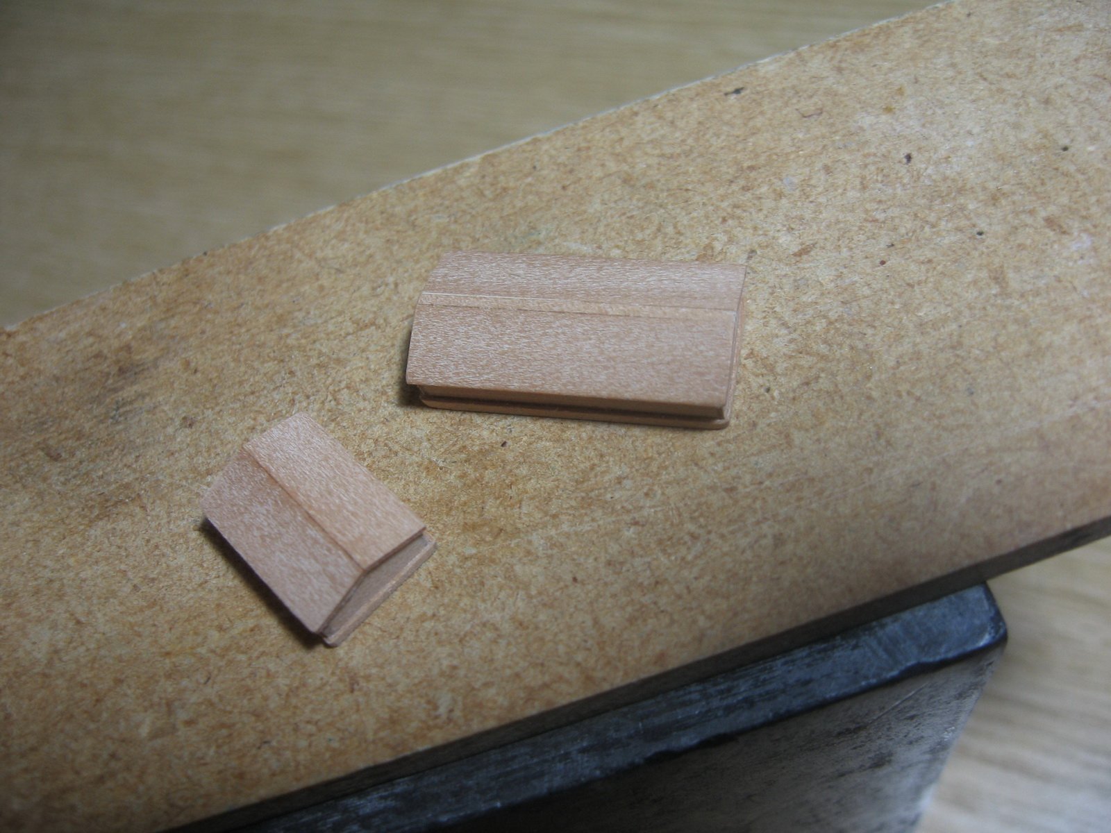
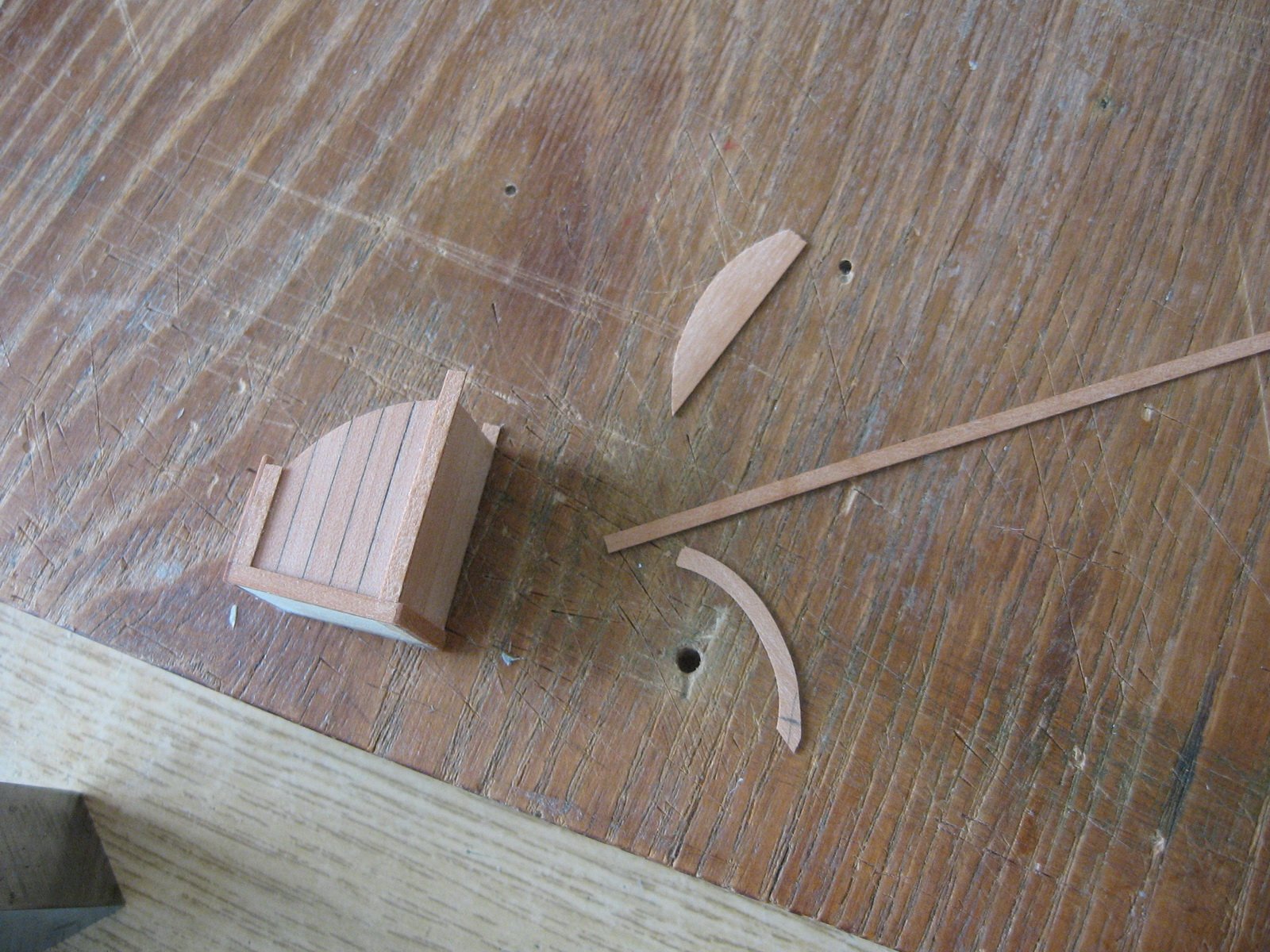
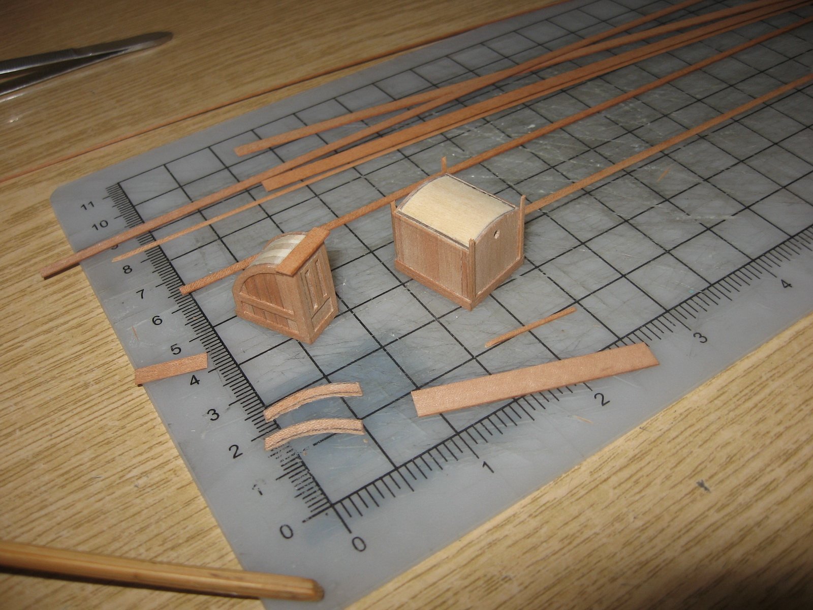
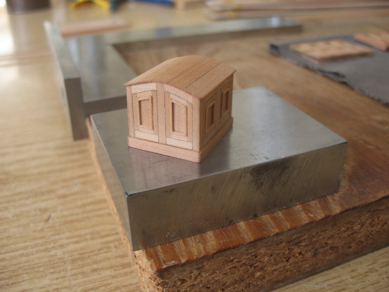
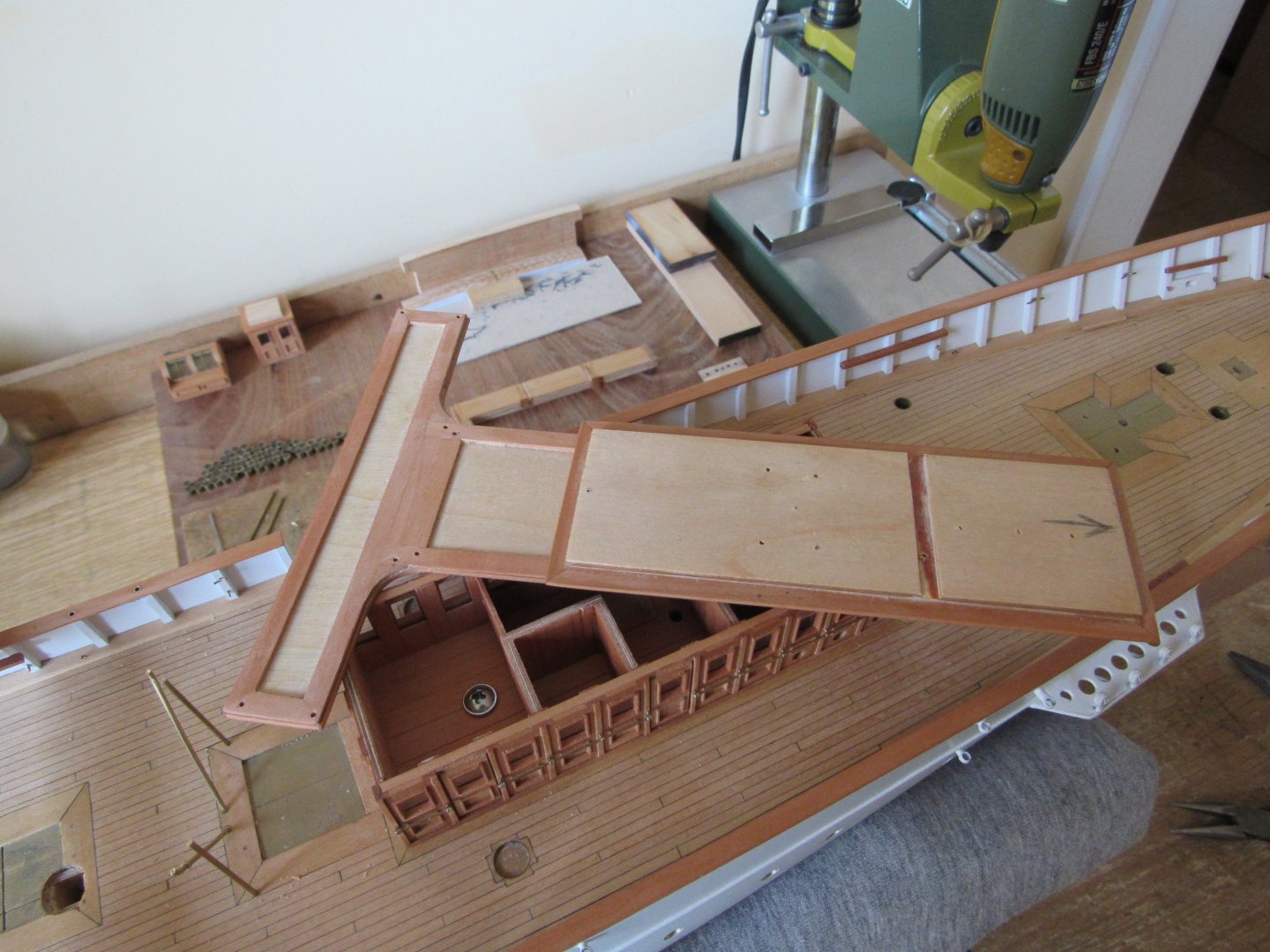
Thank you Eberhard. Roof is from tree seperate sheets glued on top of another. I only shaped the edges by sanding before joining.

-
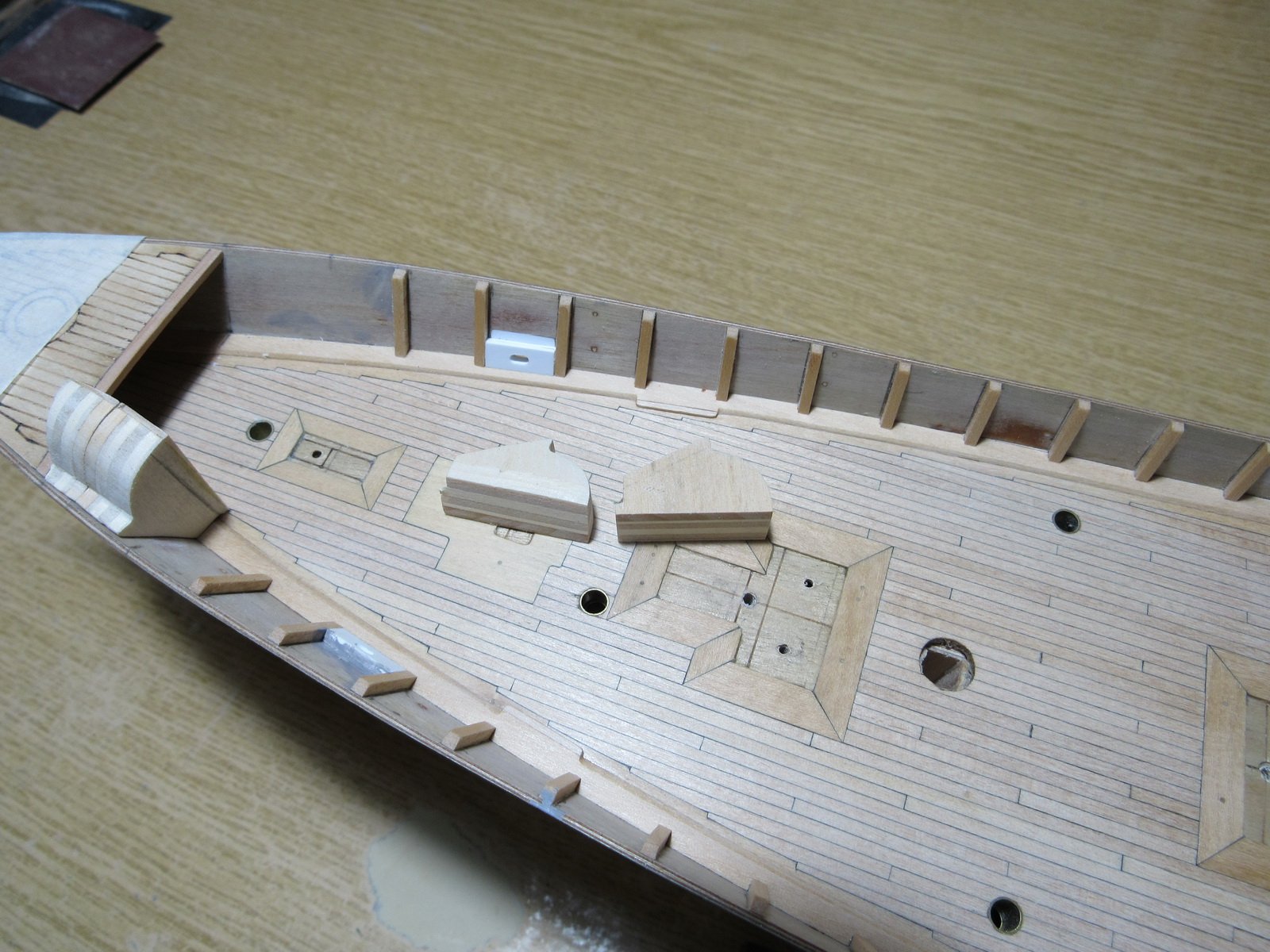
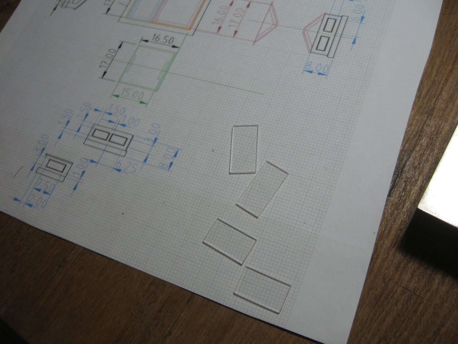
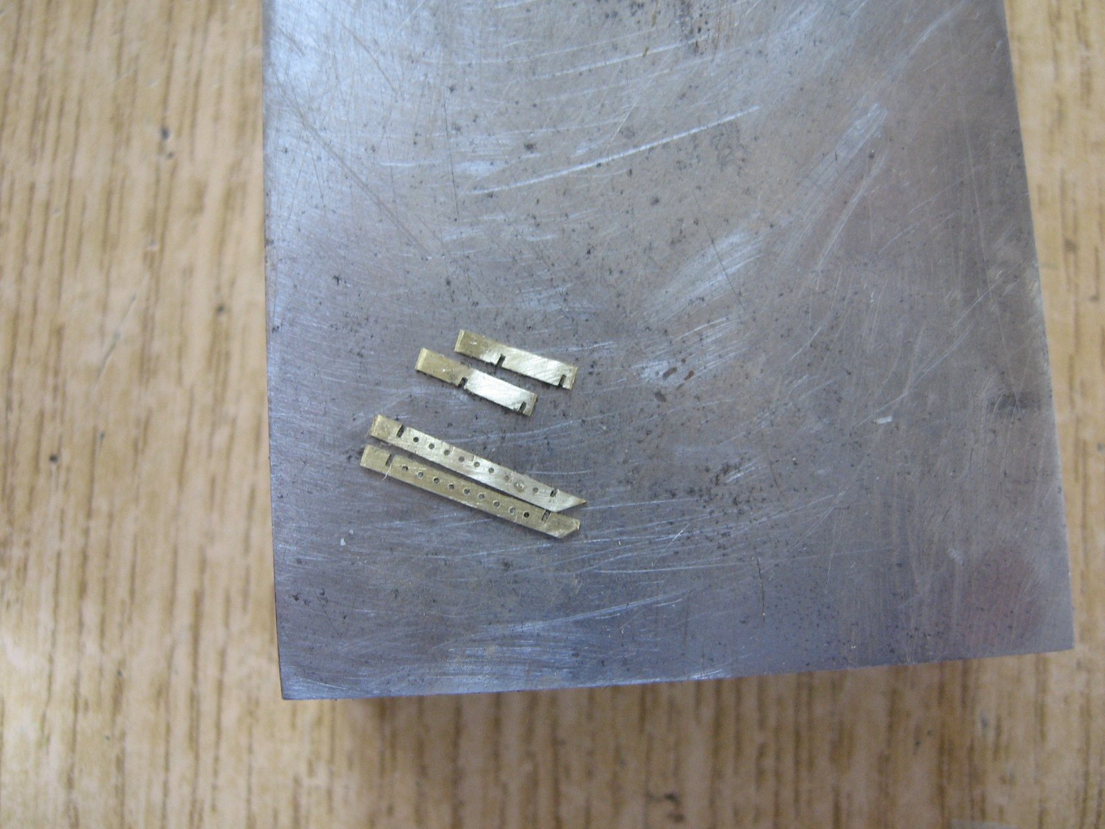
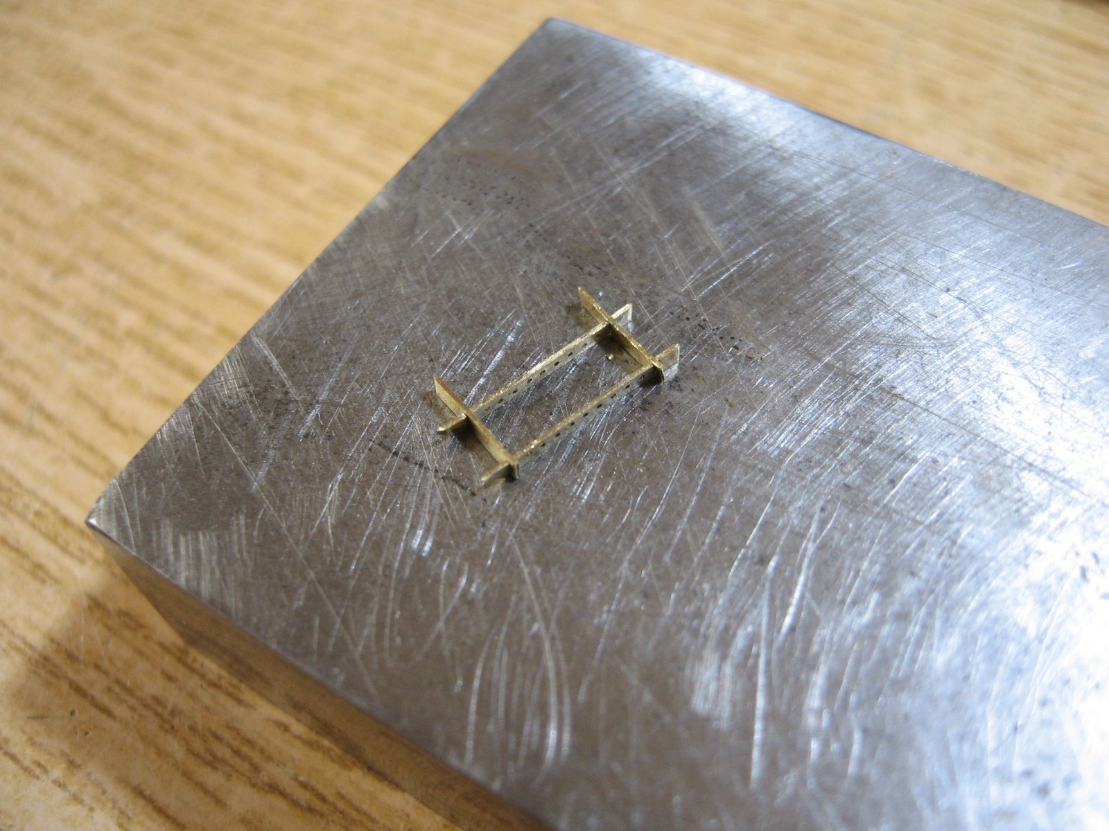
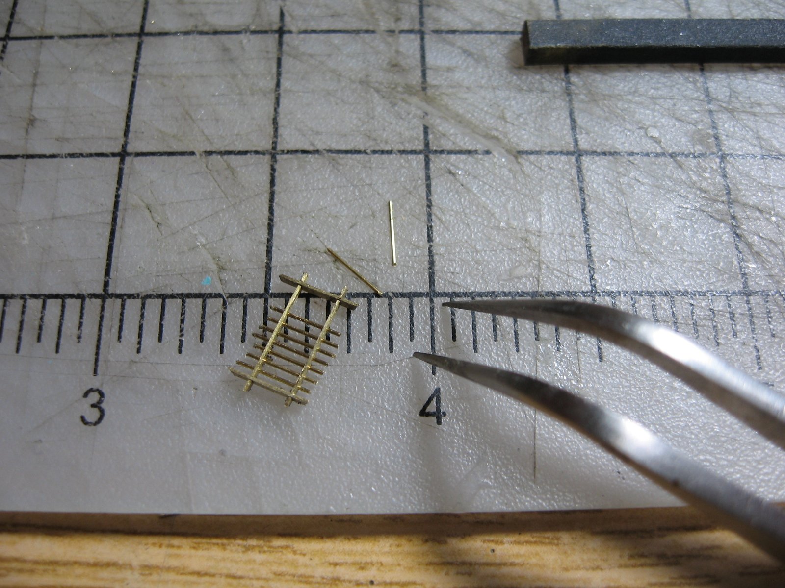
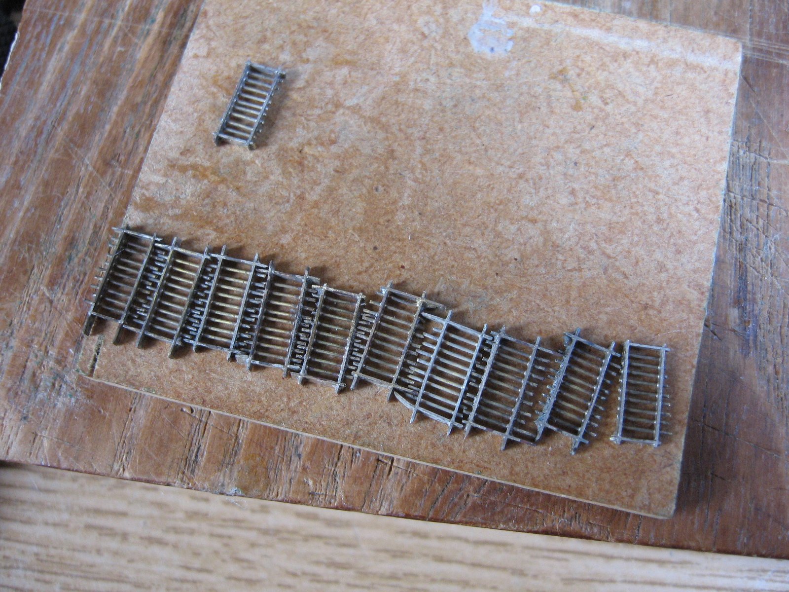
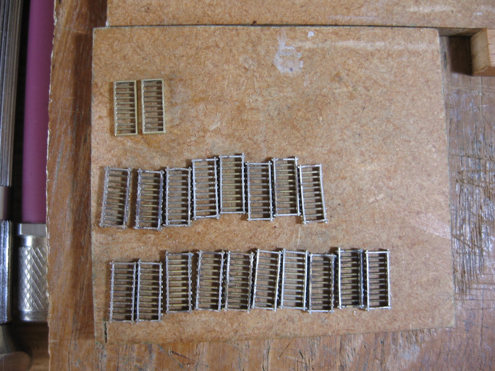
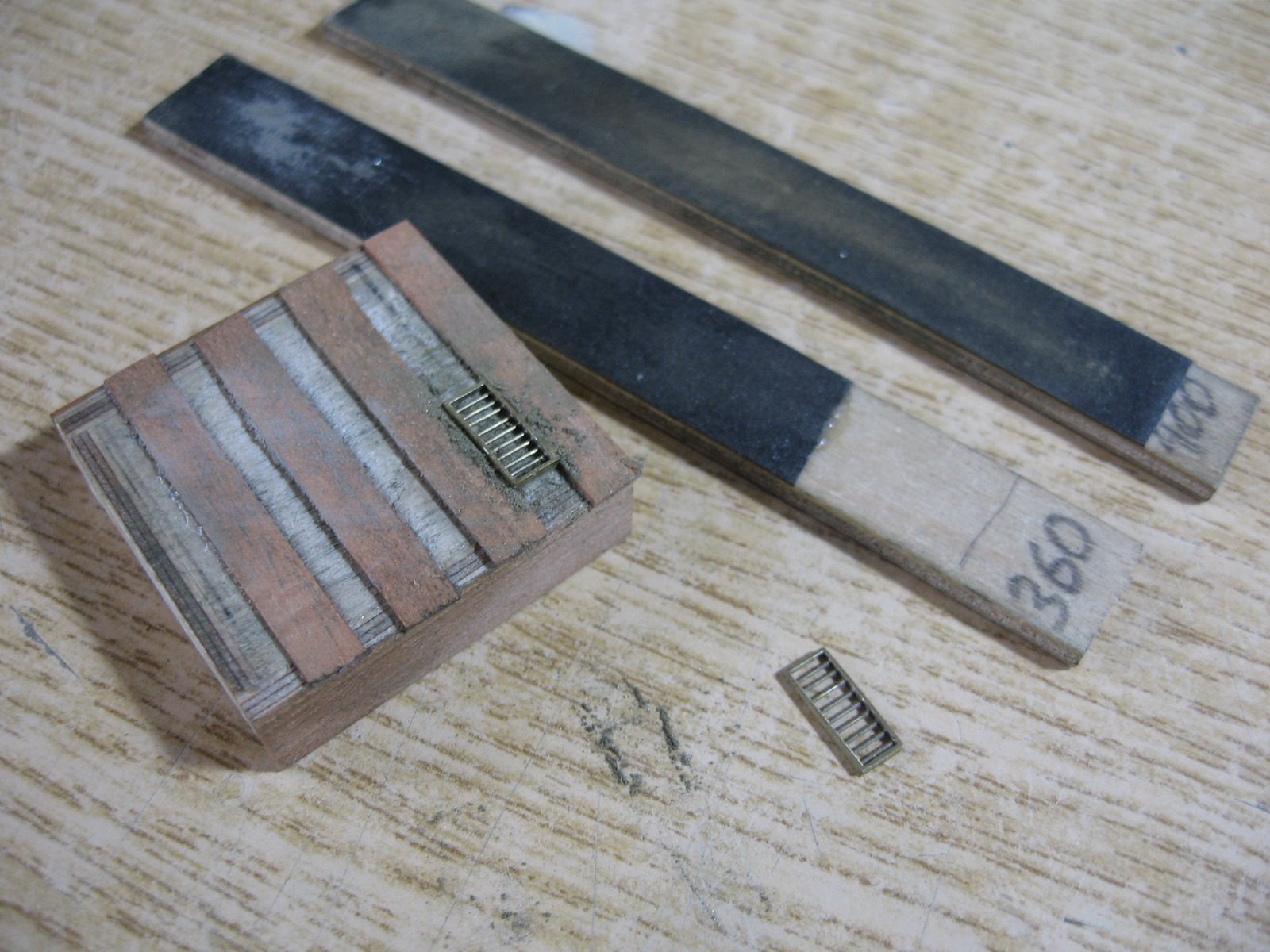
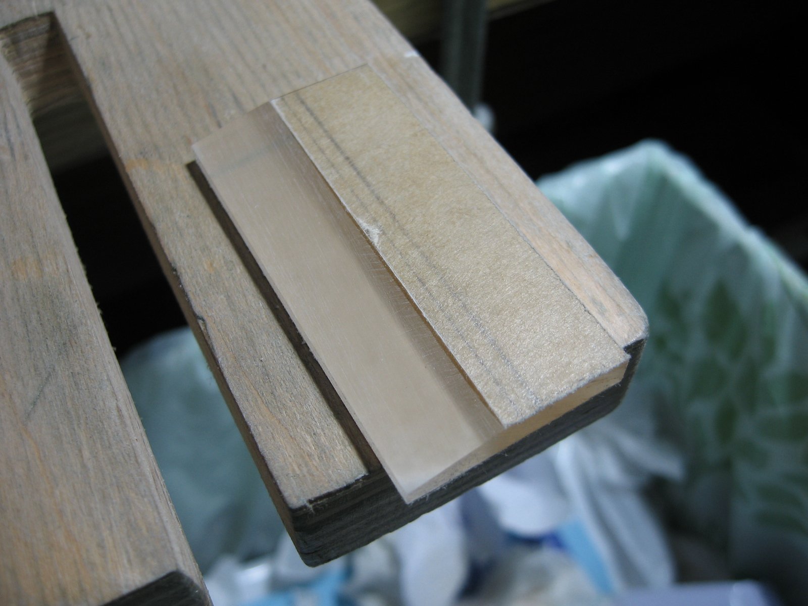
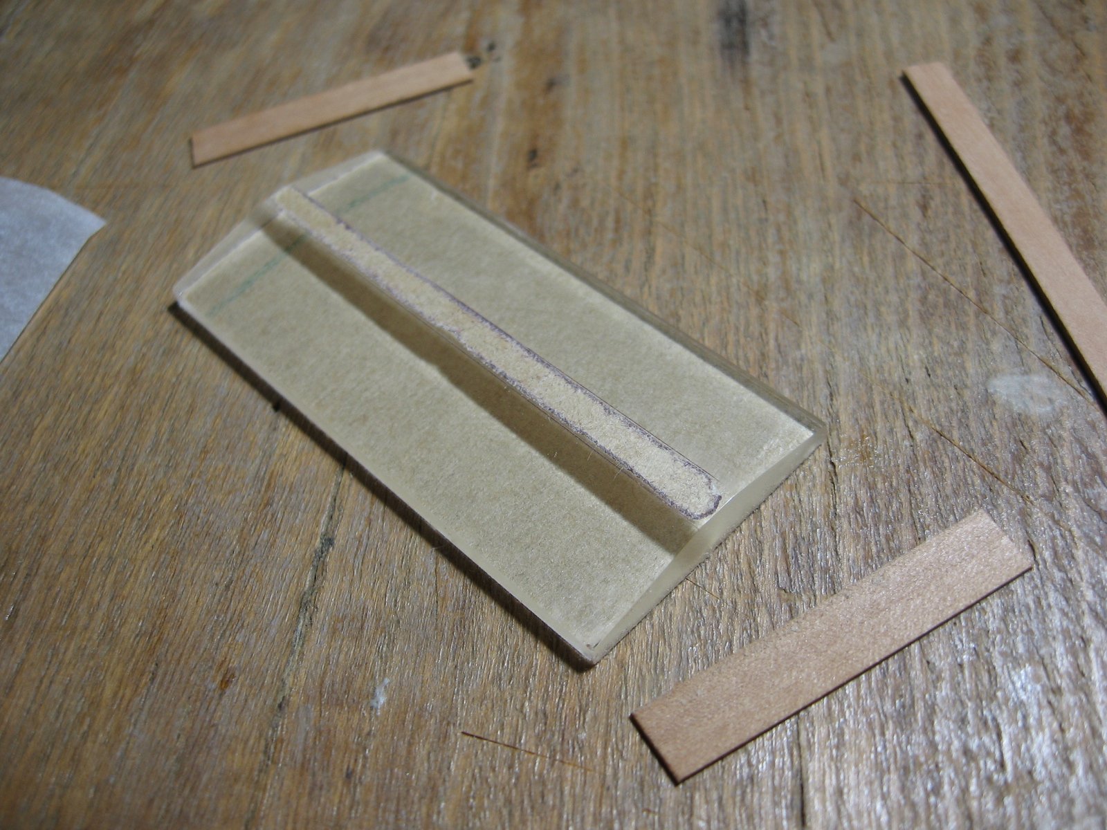
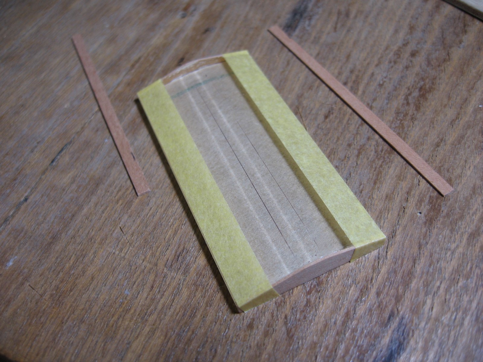
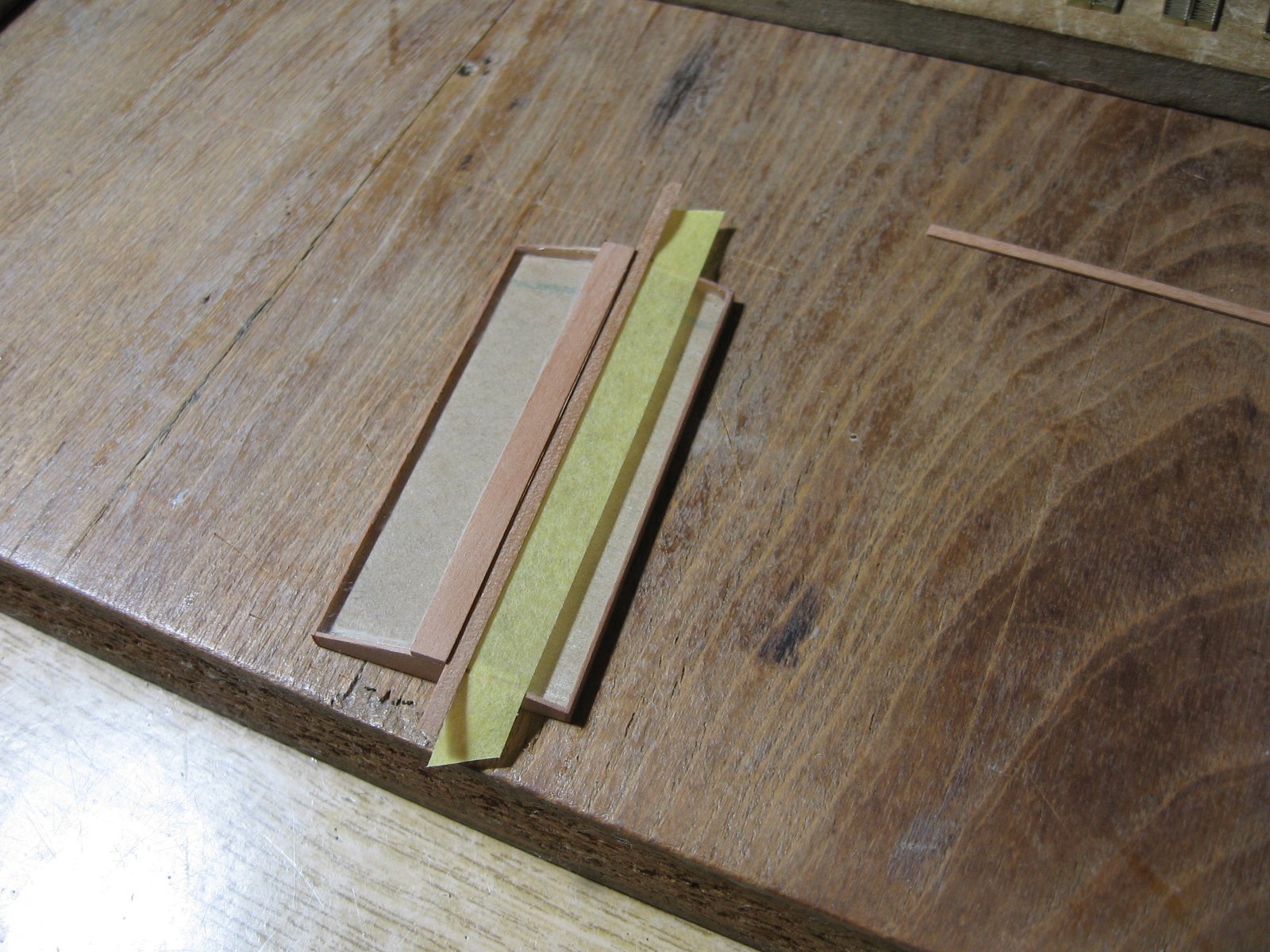
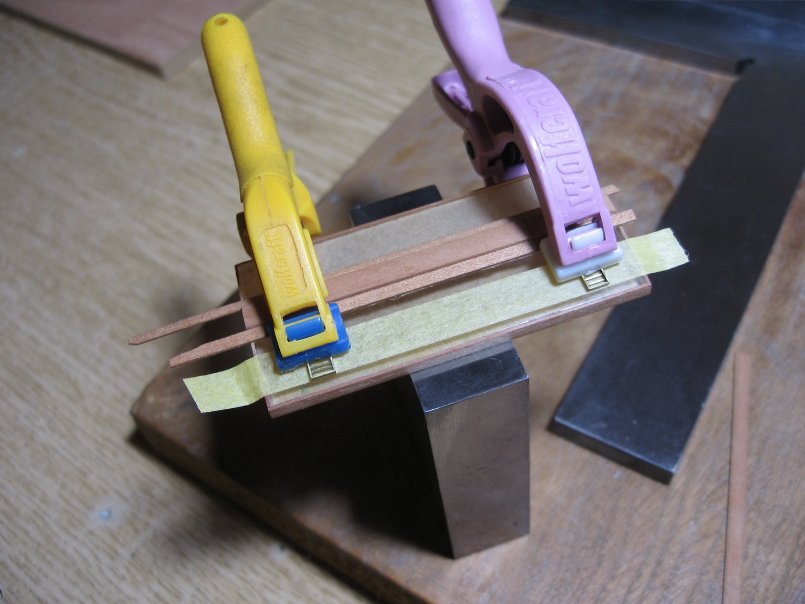
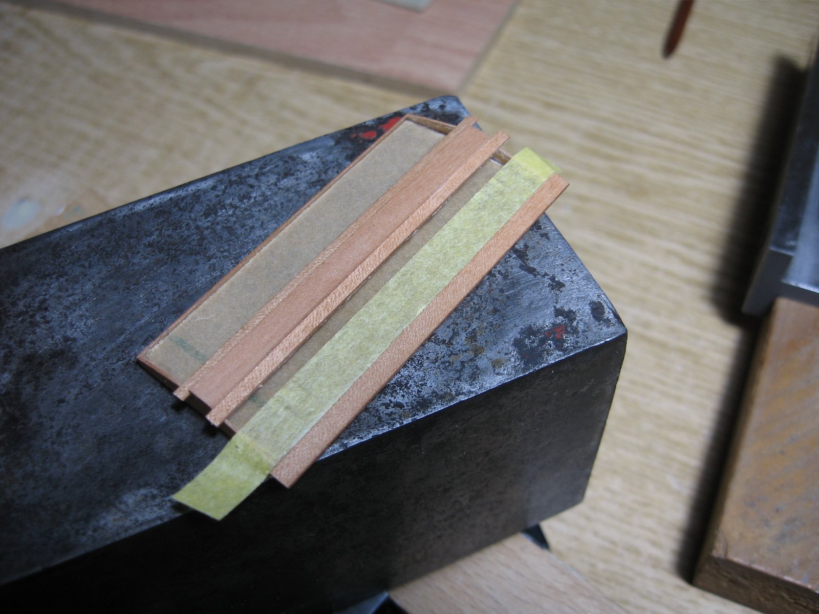
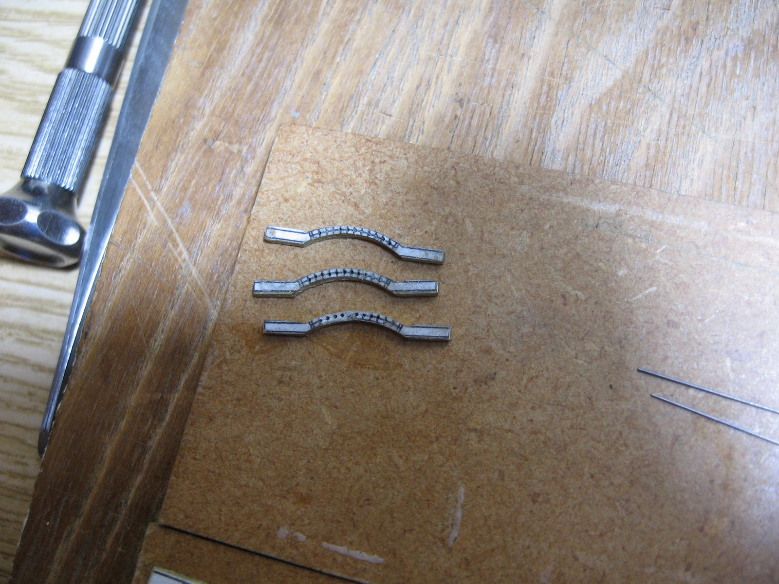
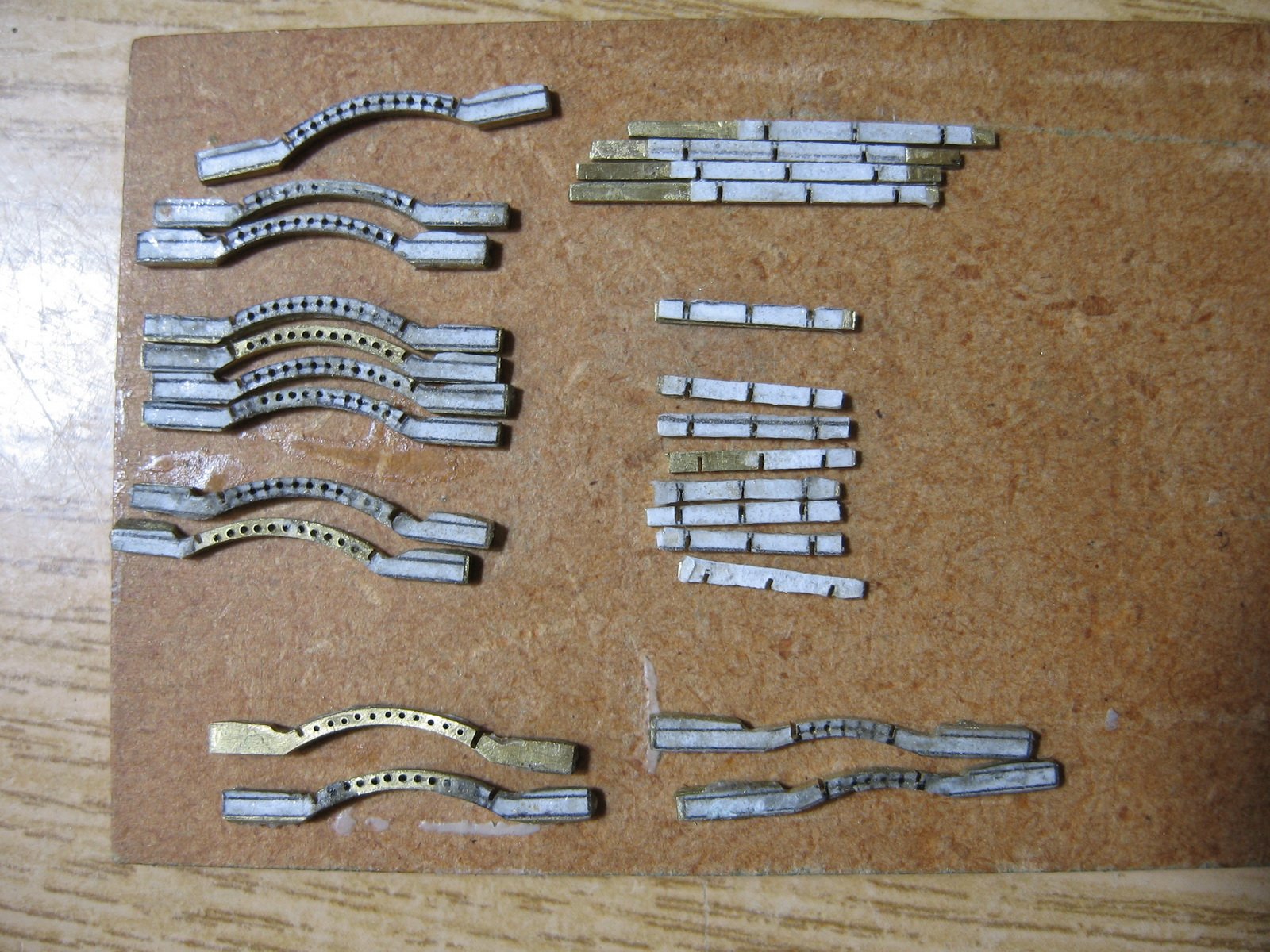
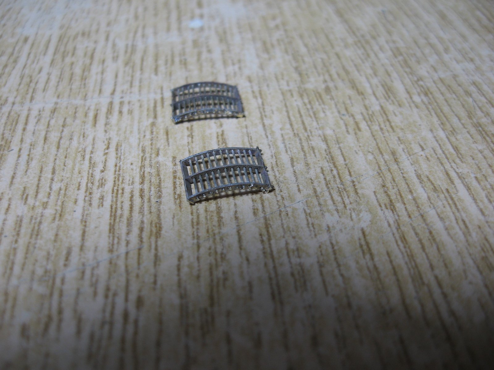
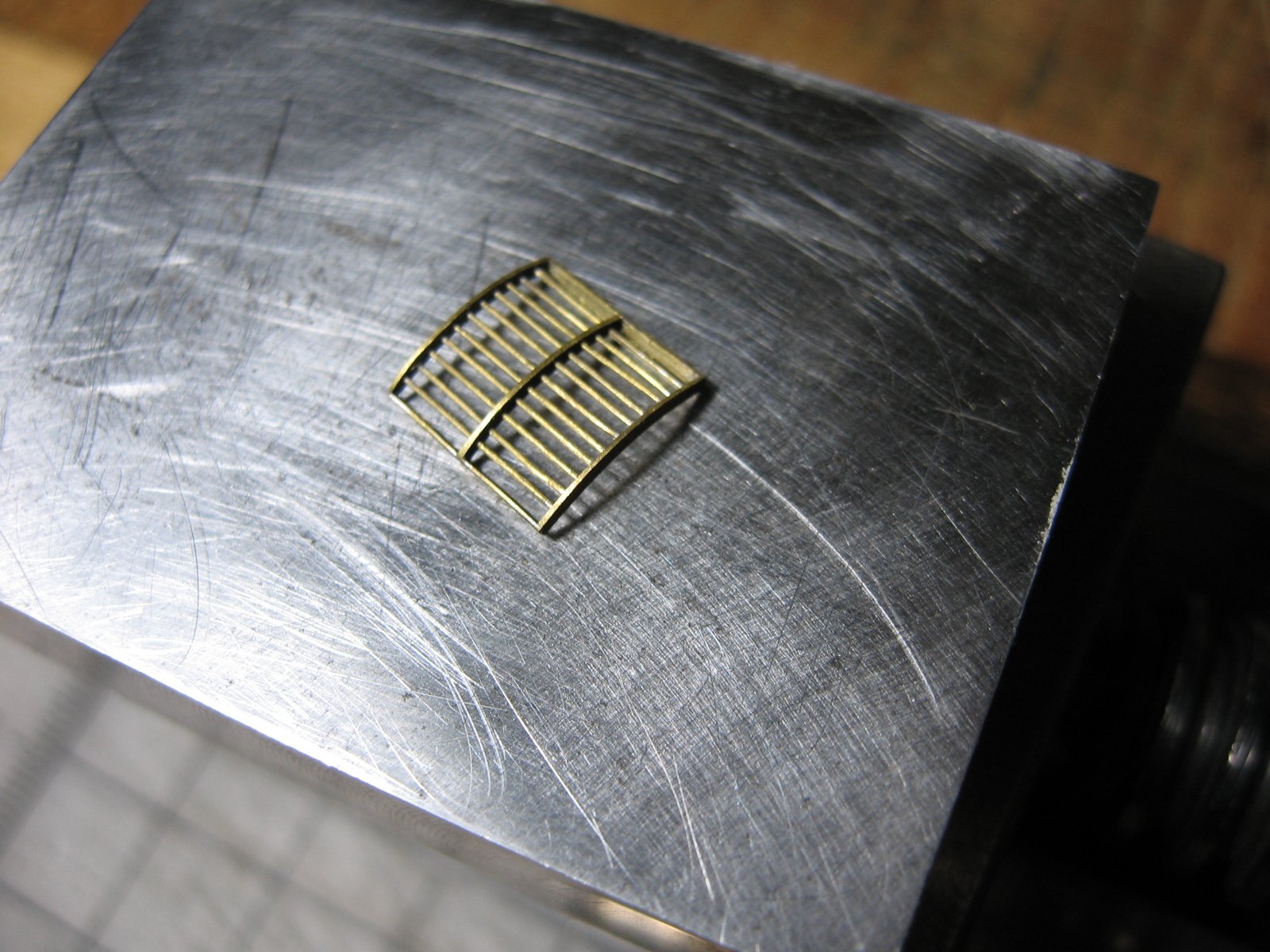
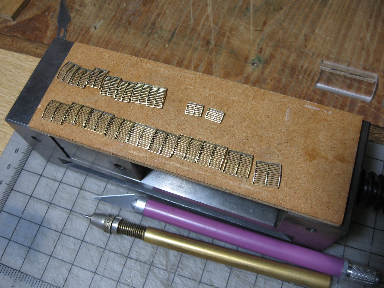
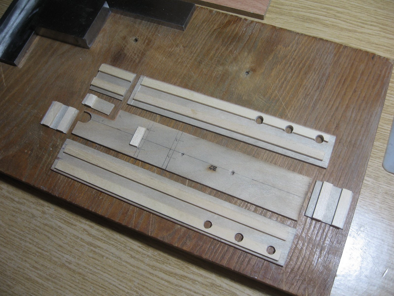
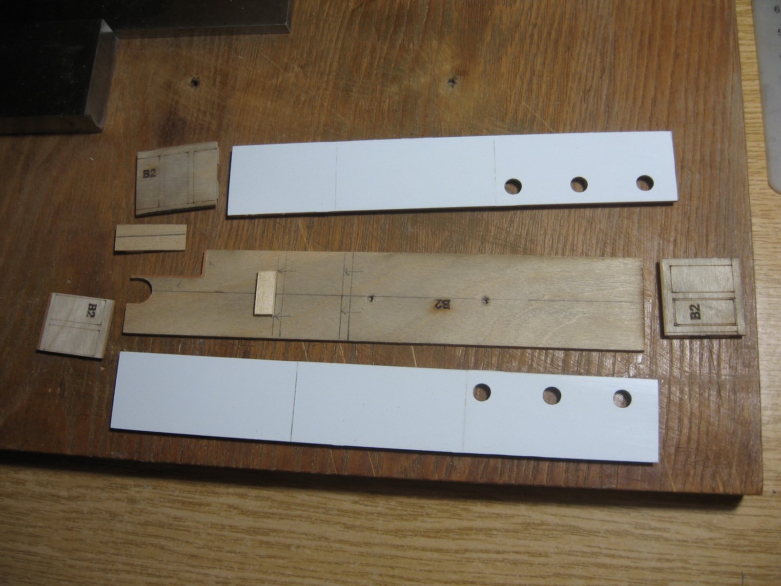
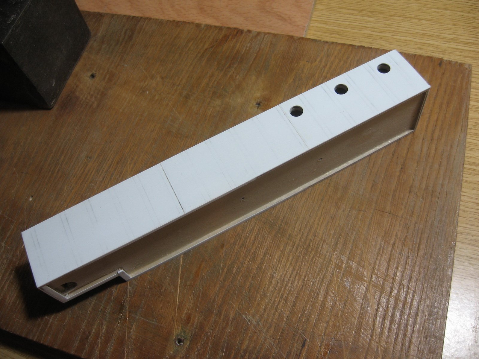
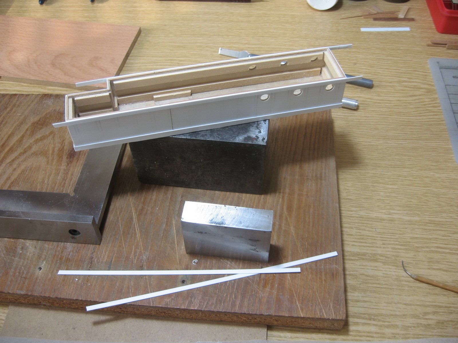
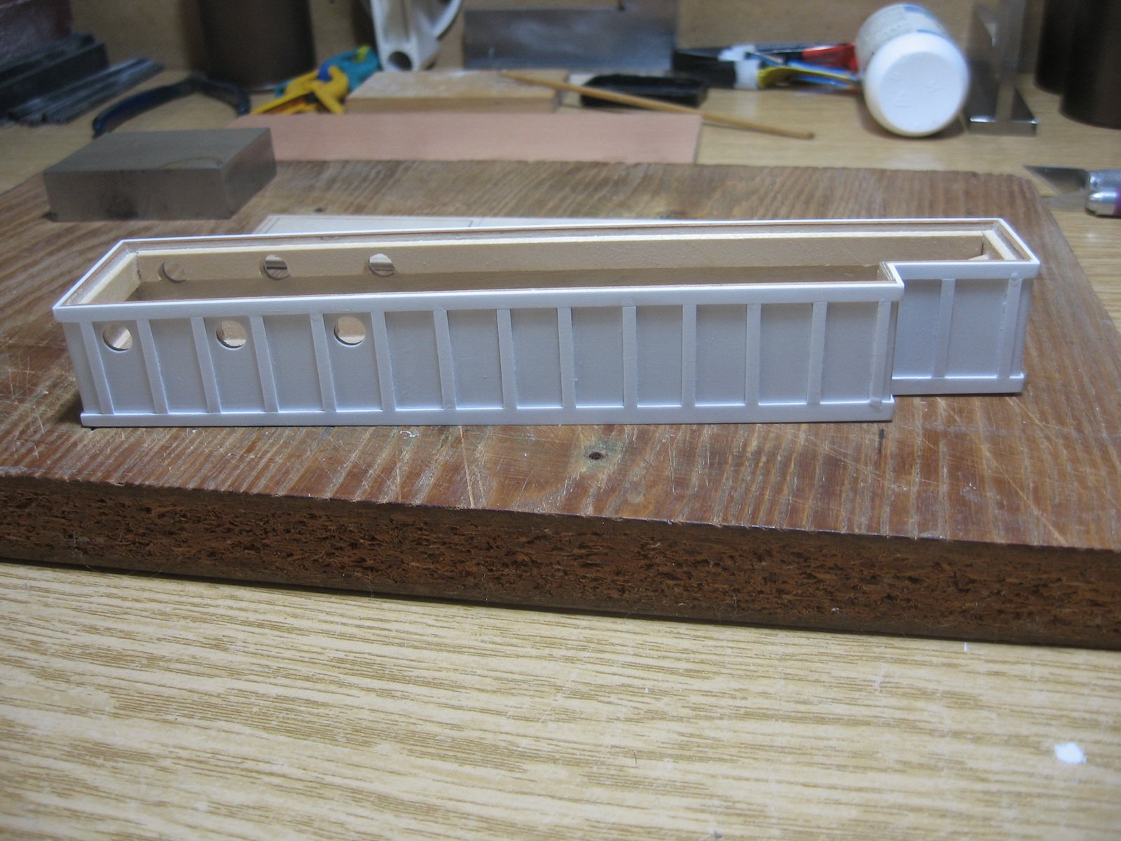
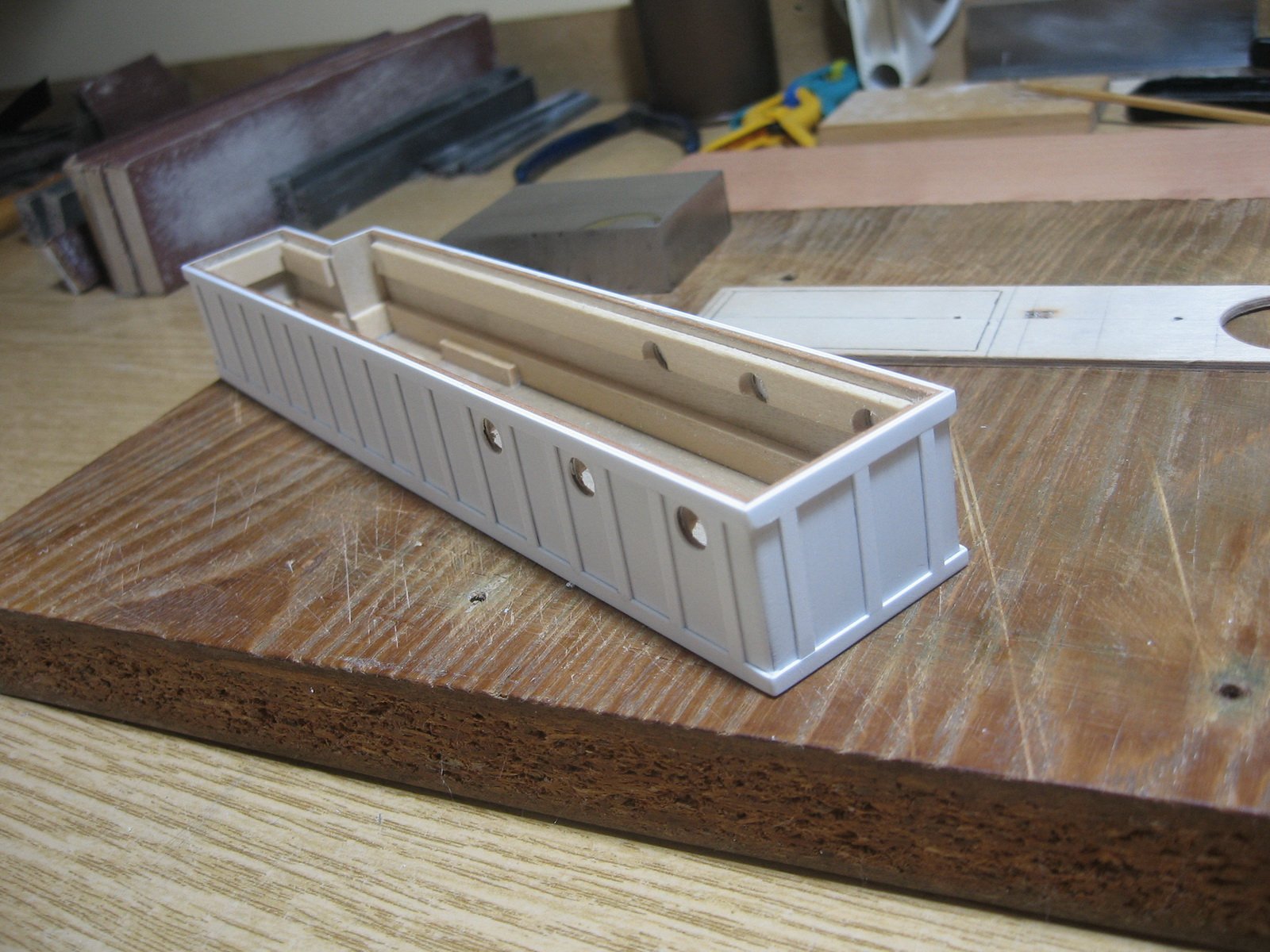
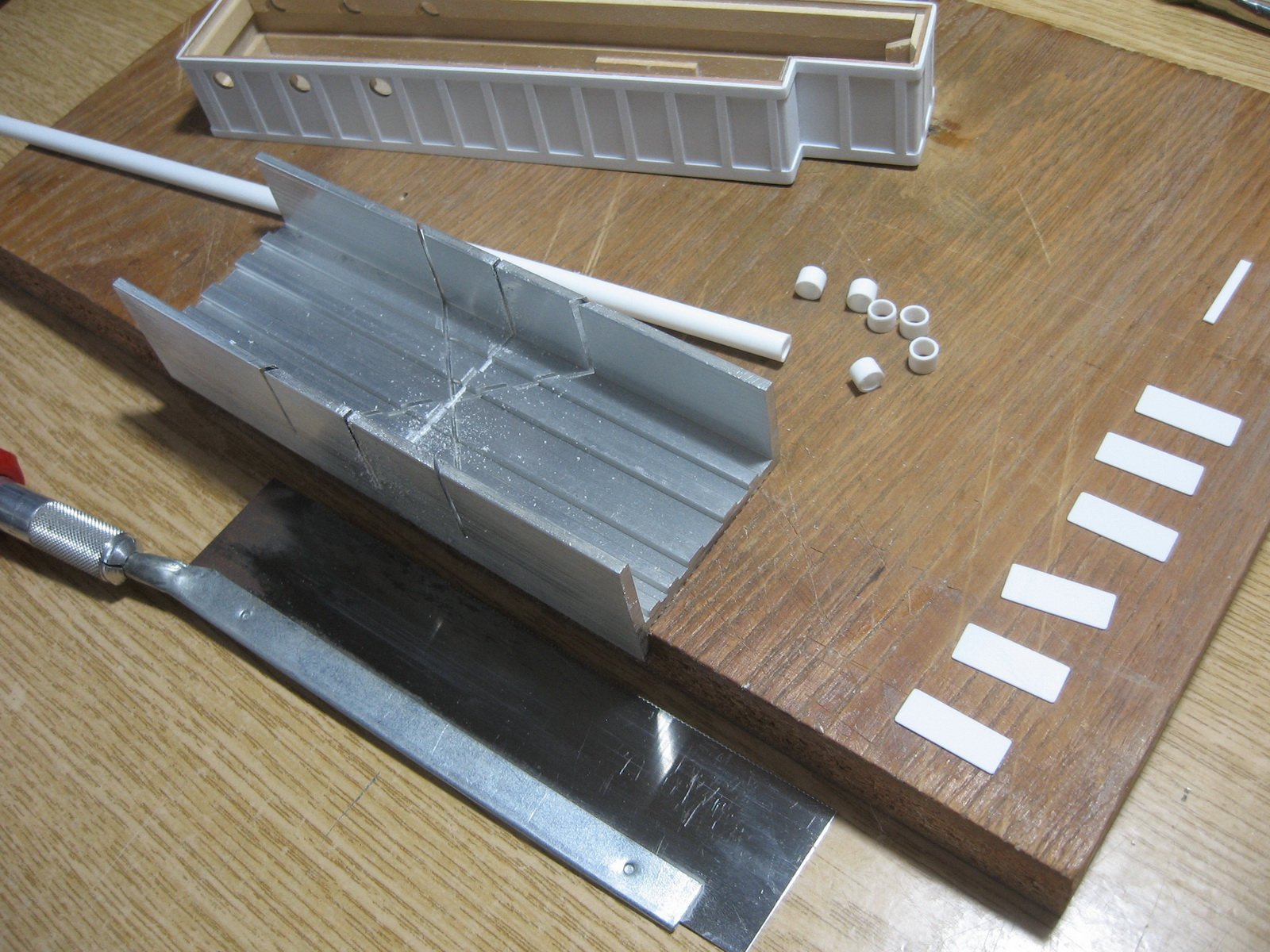
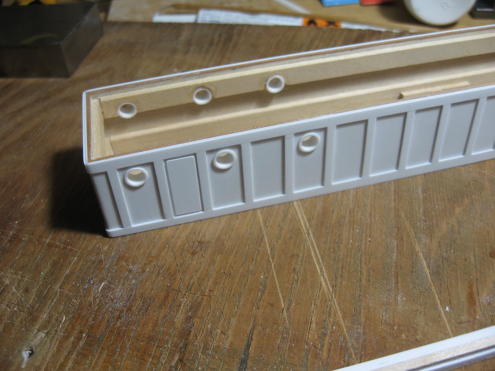
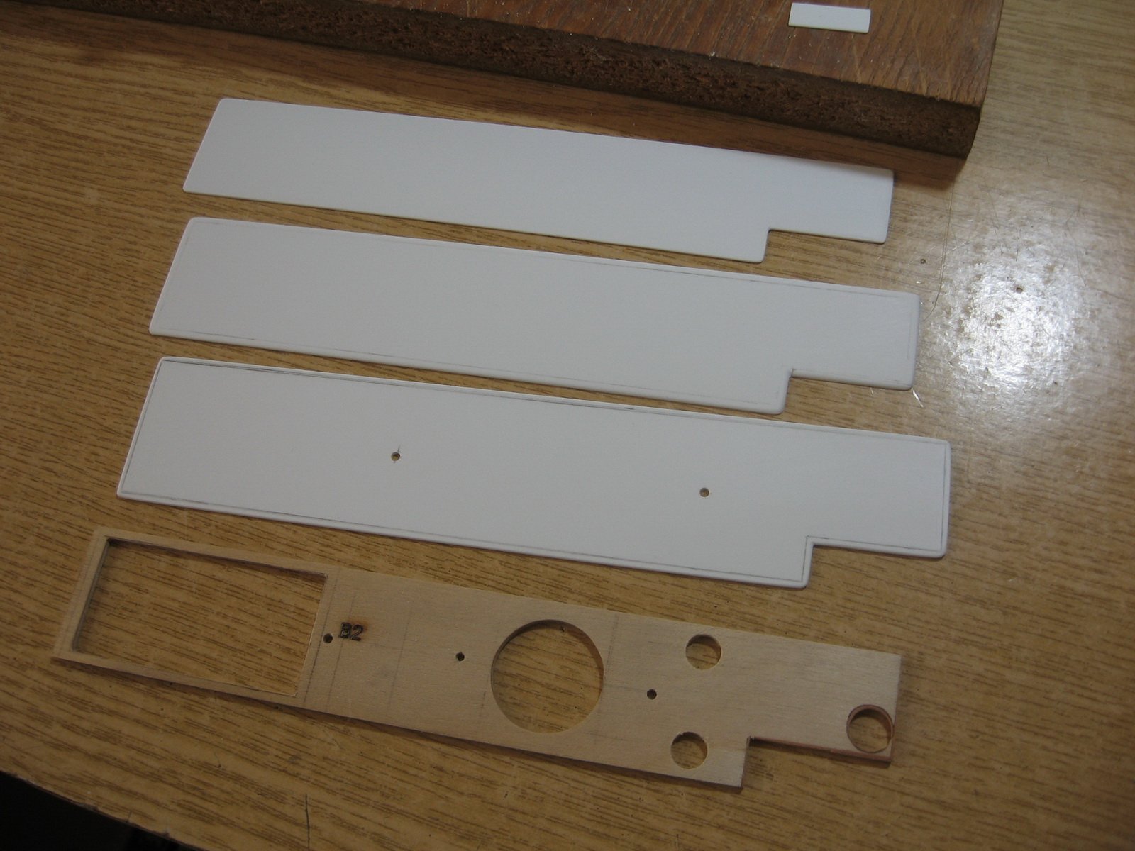
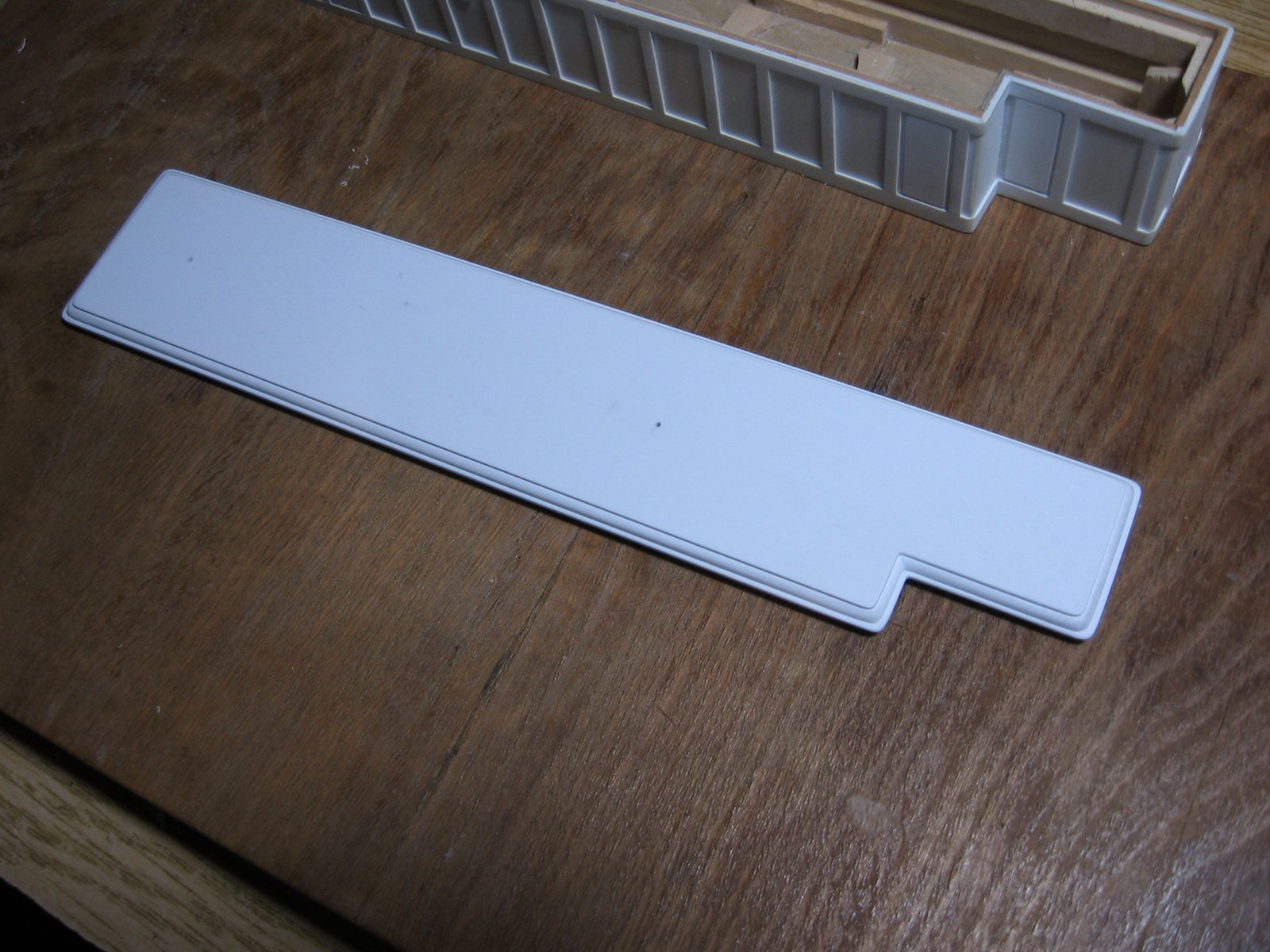
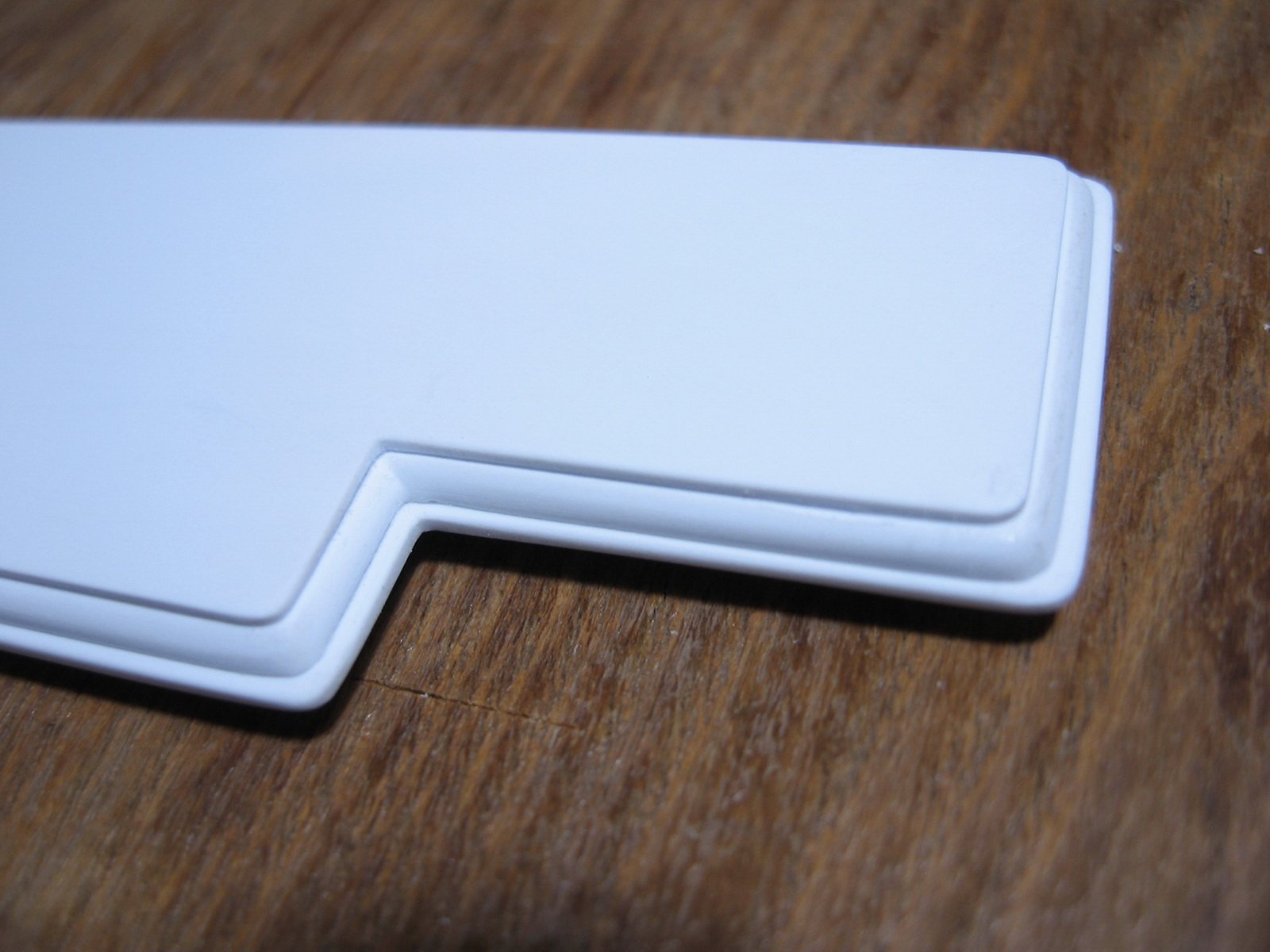
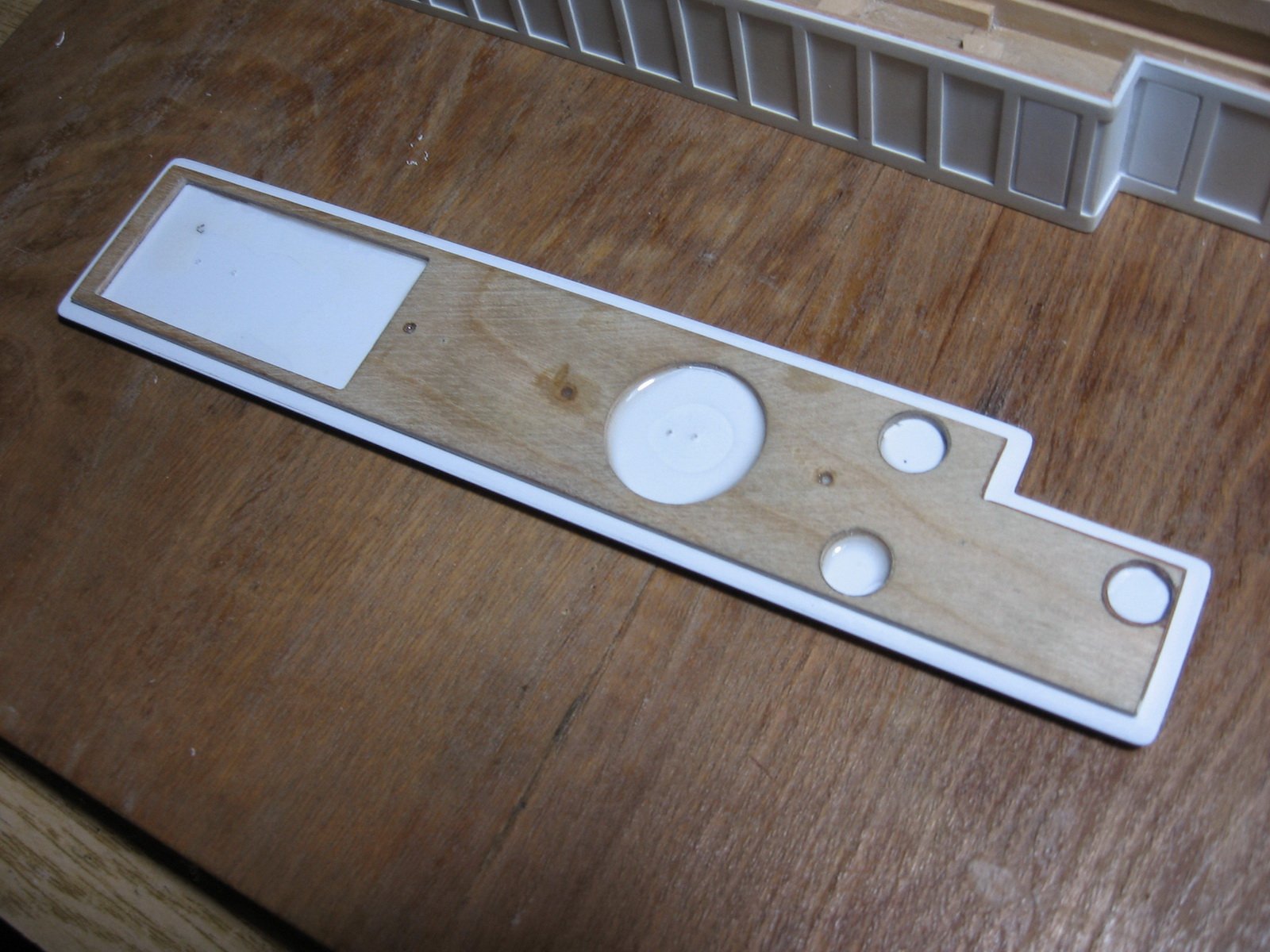
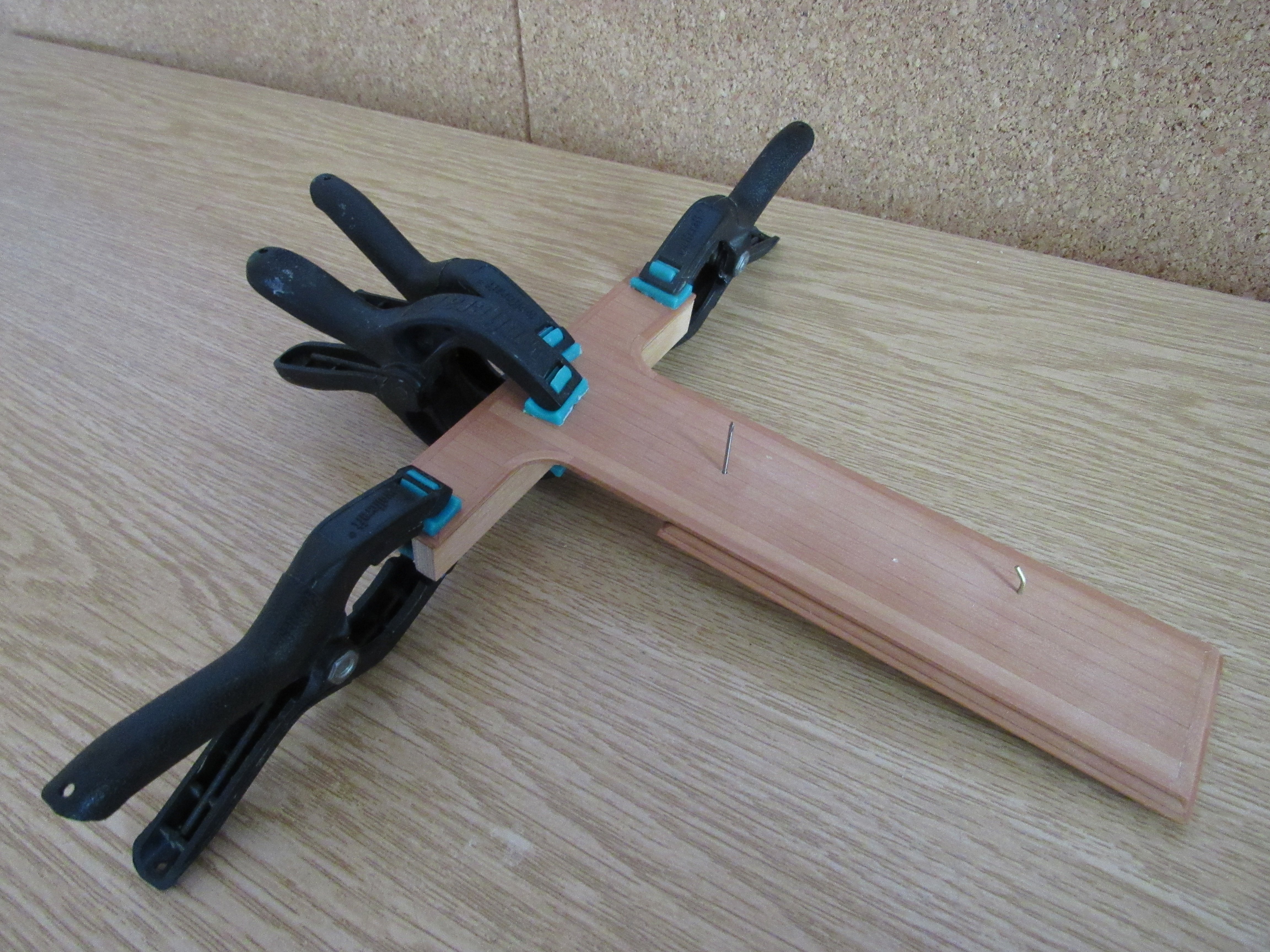
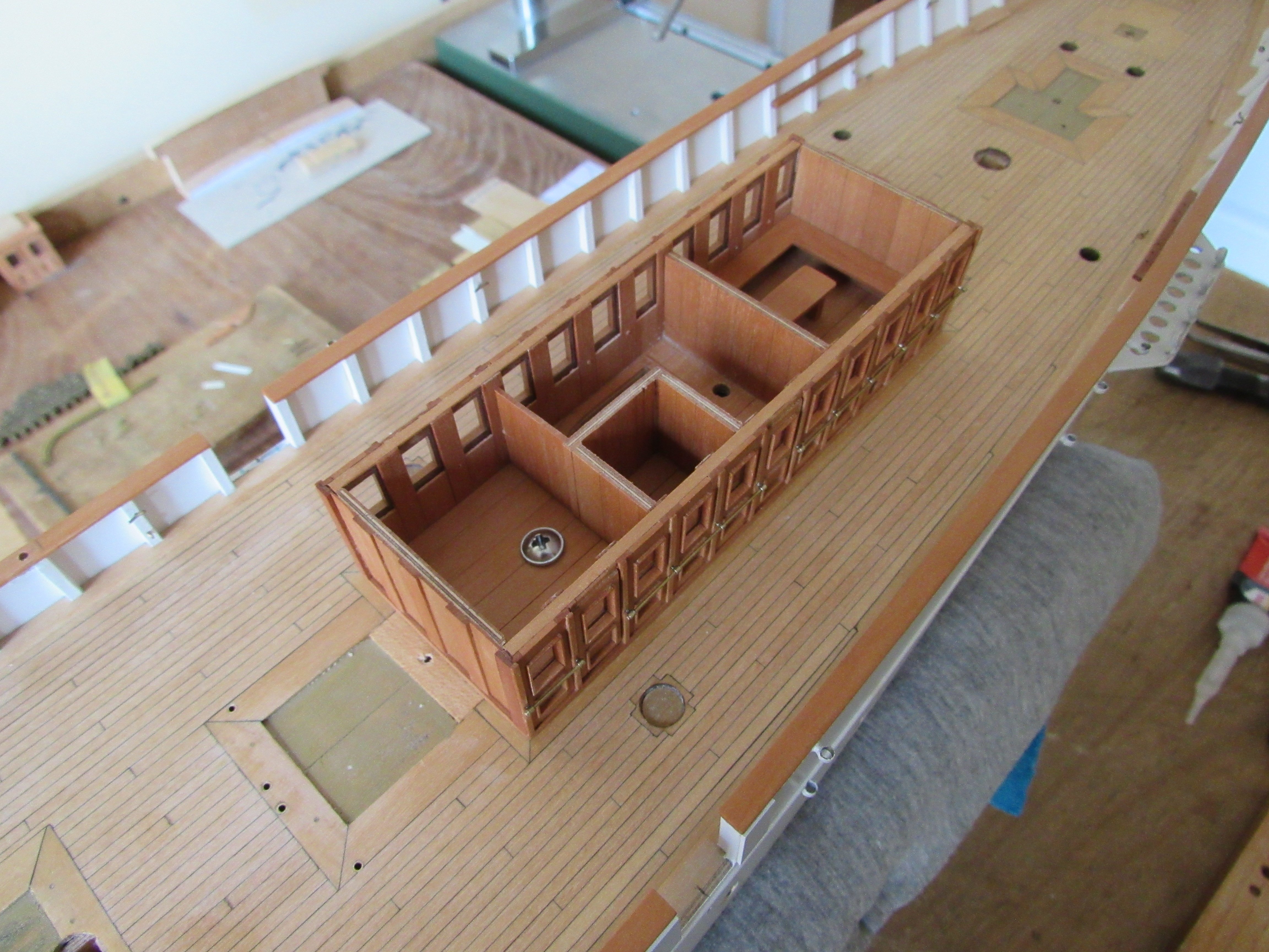
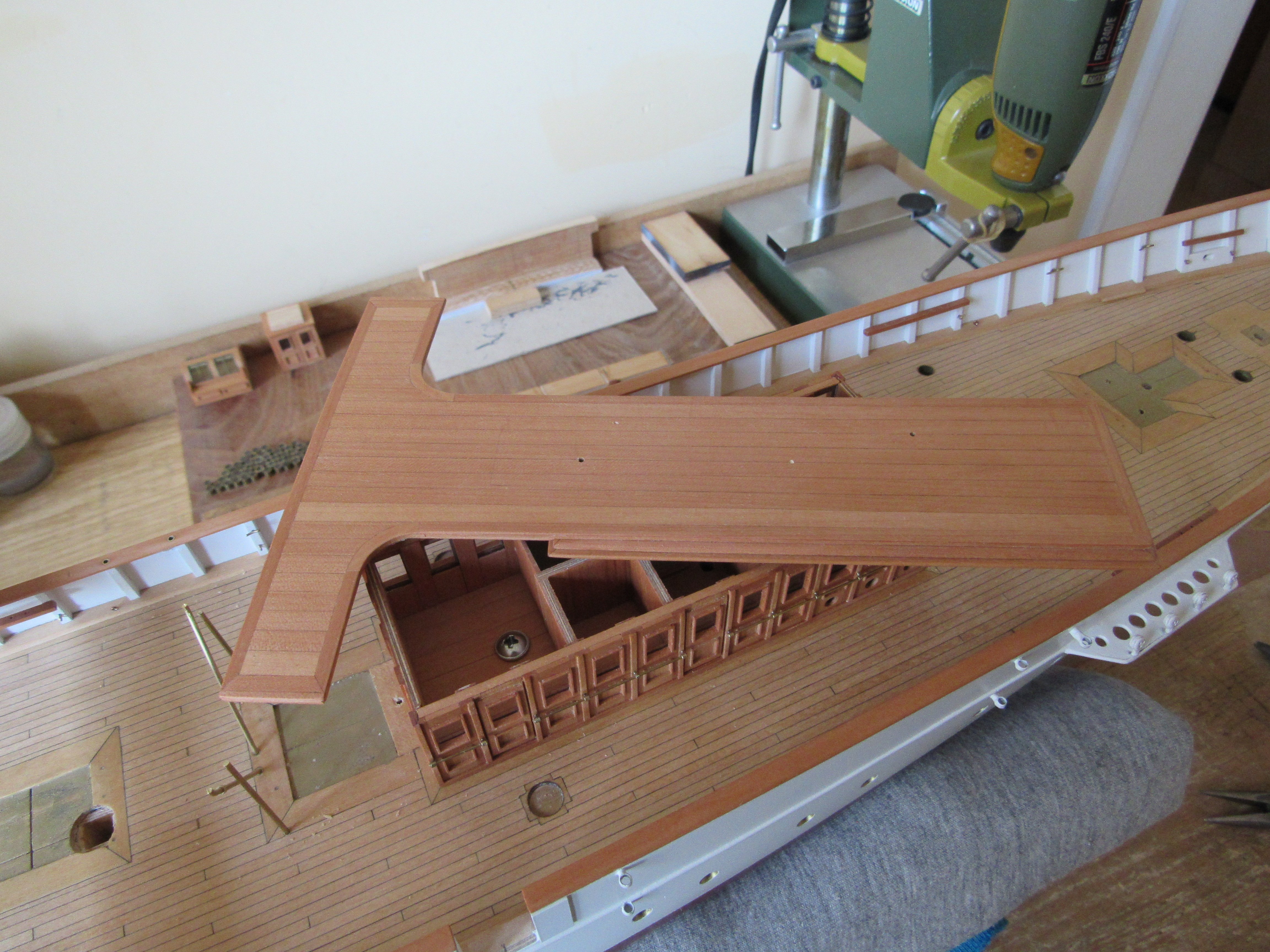
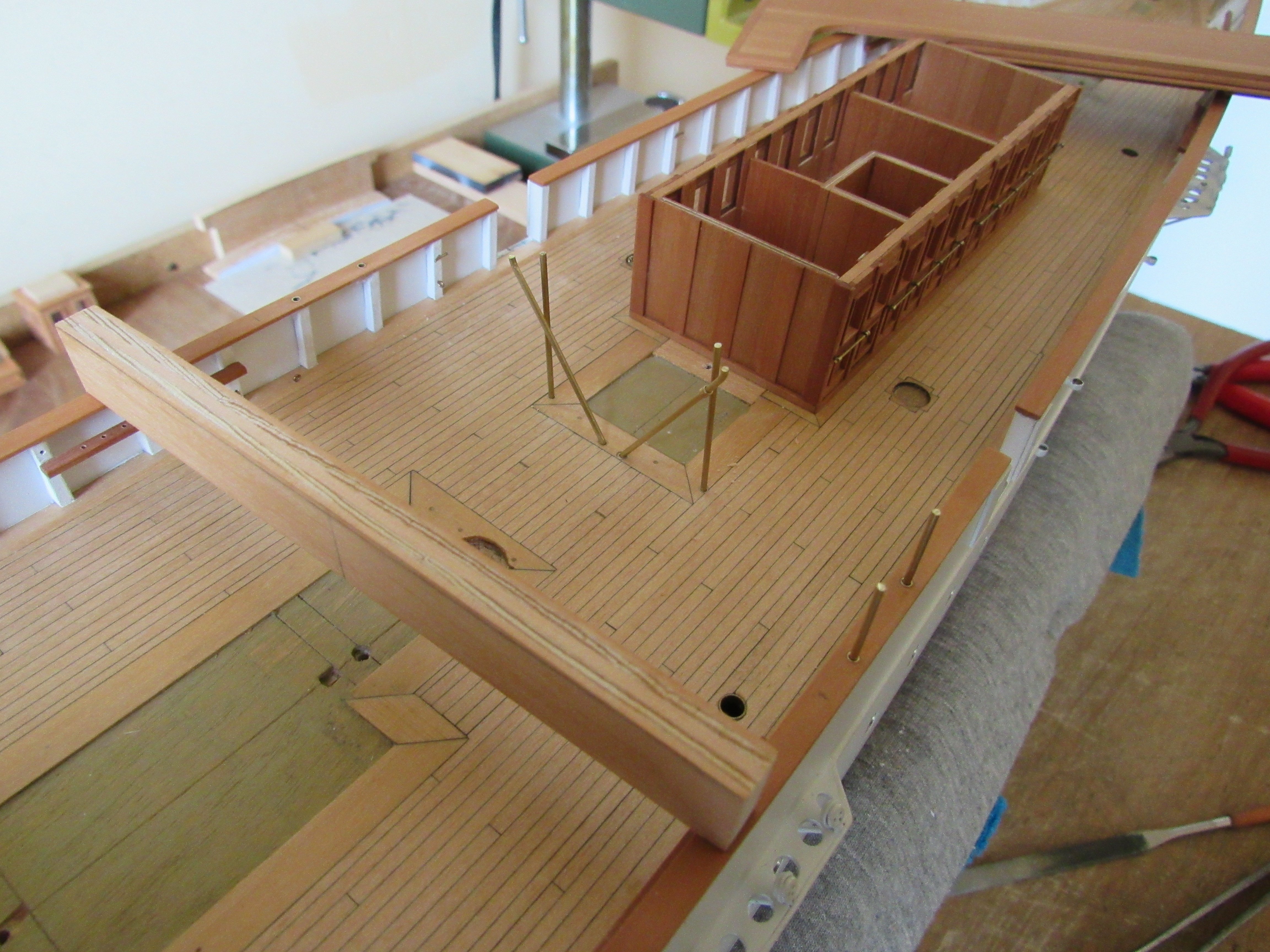
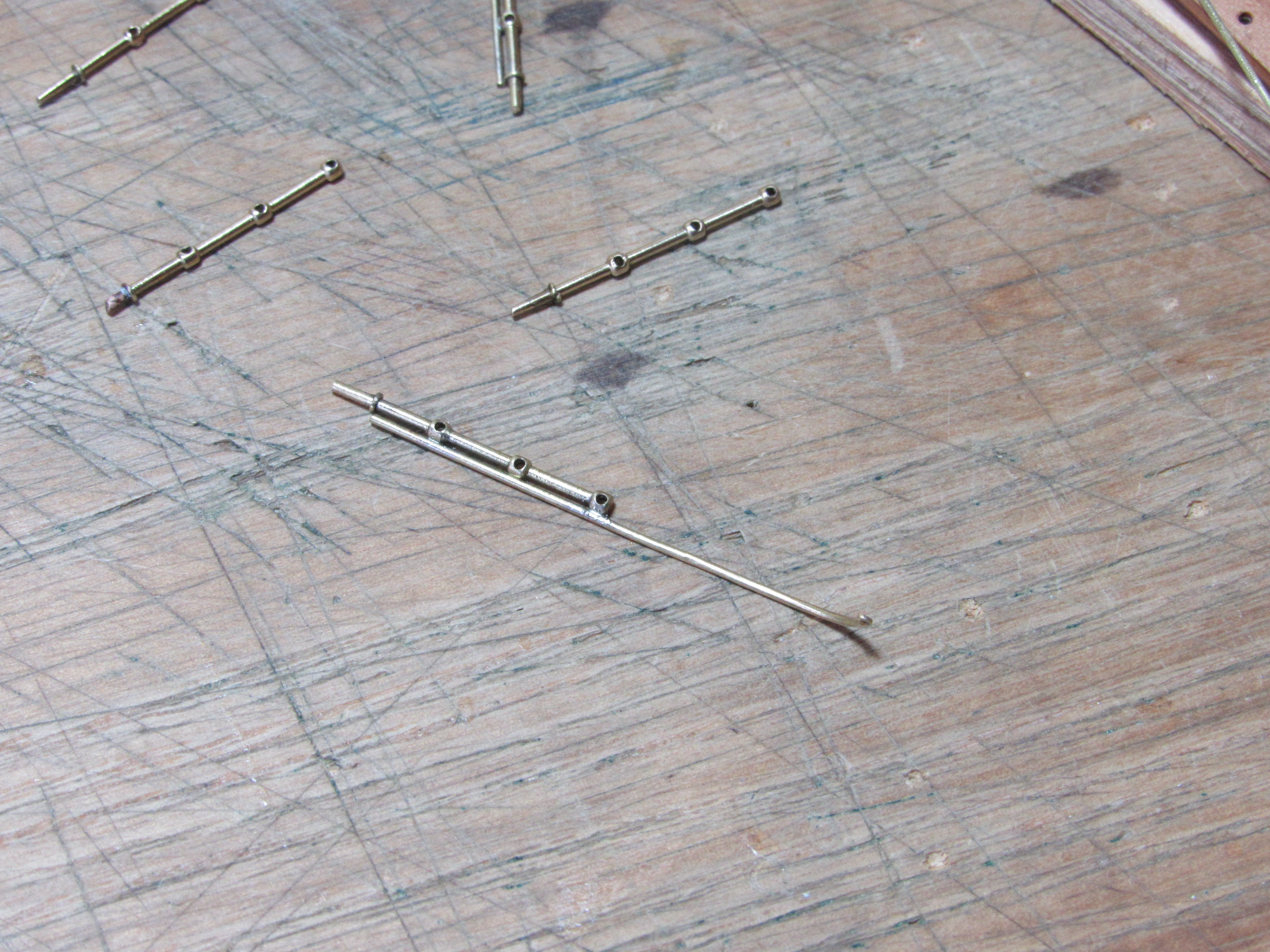
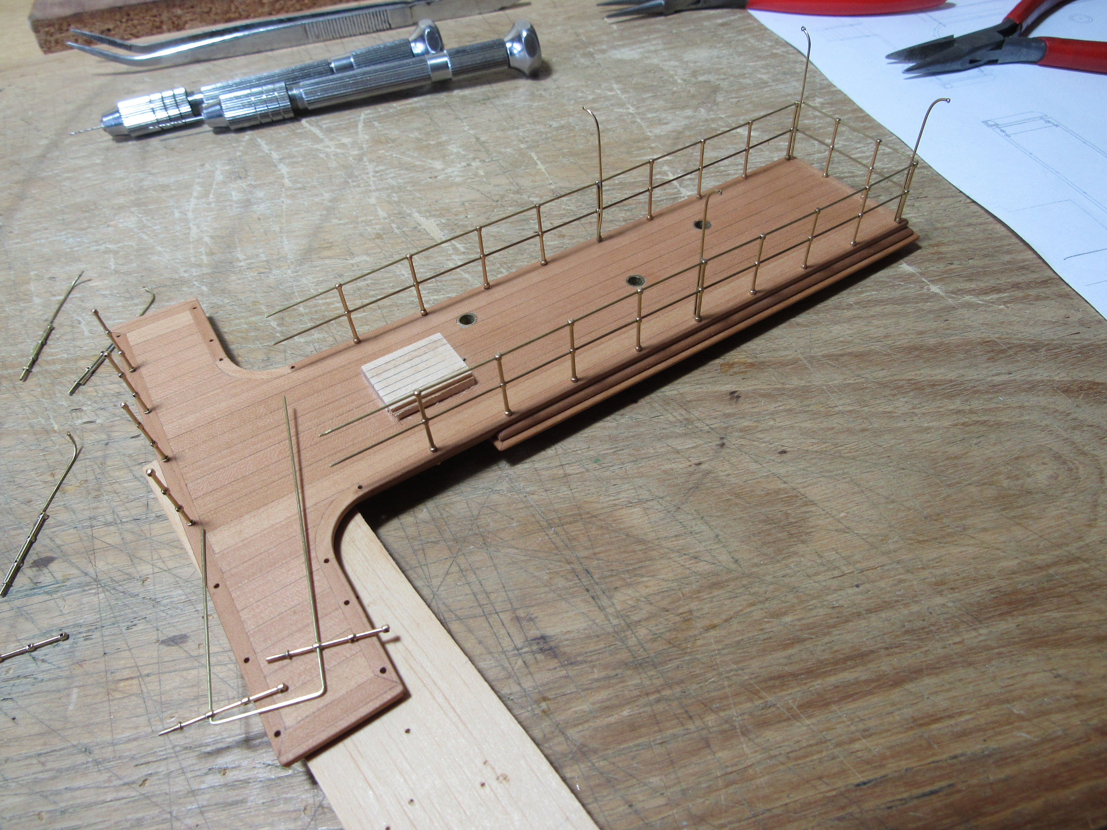
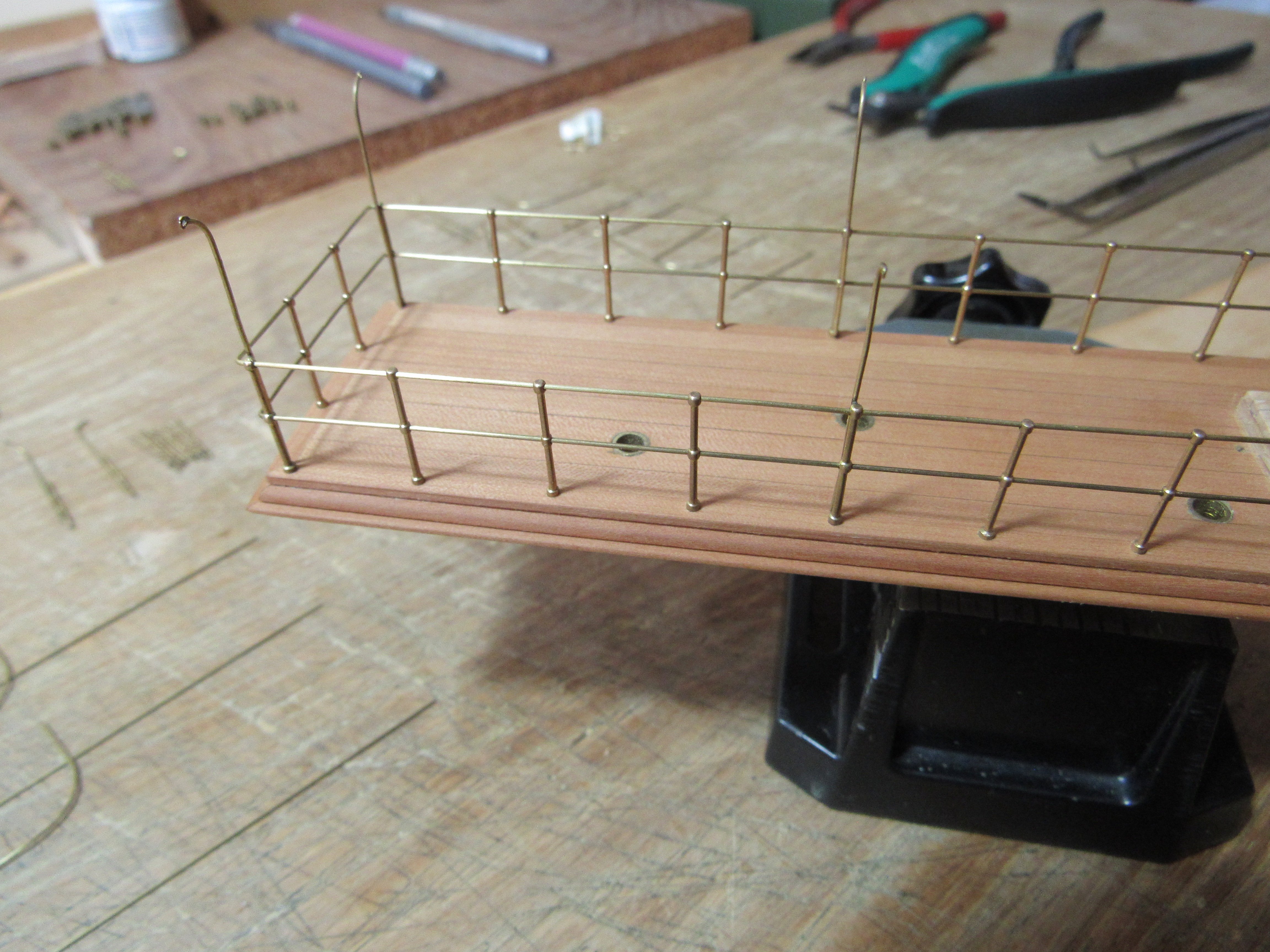
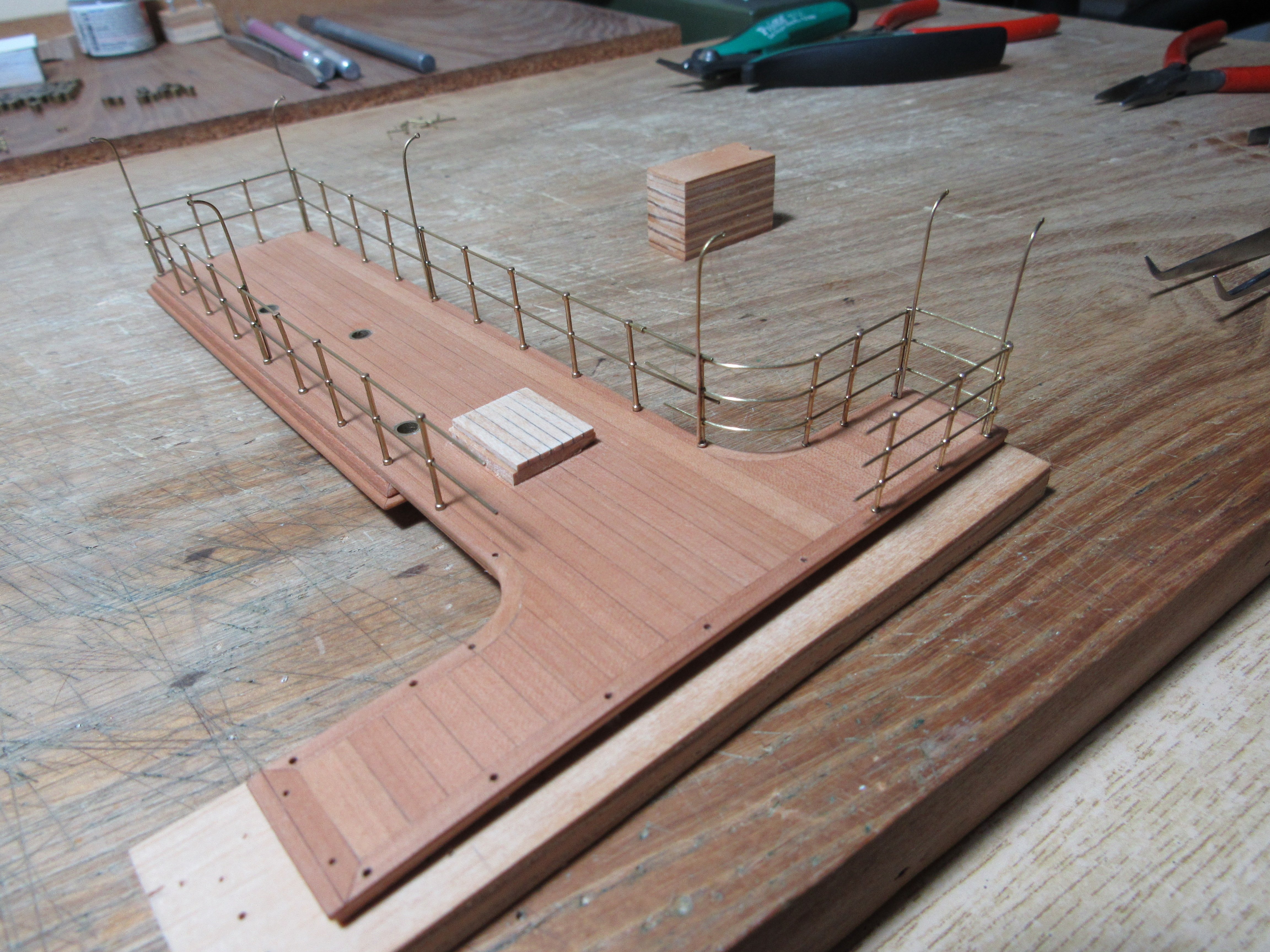
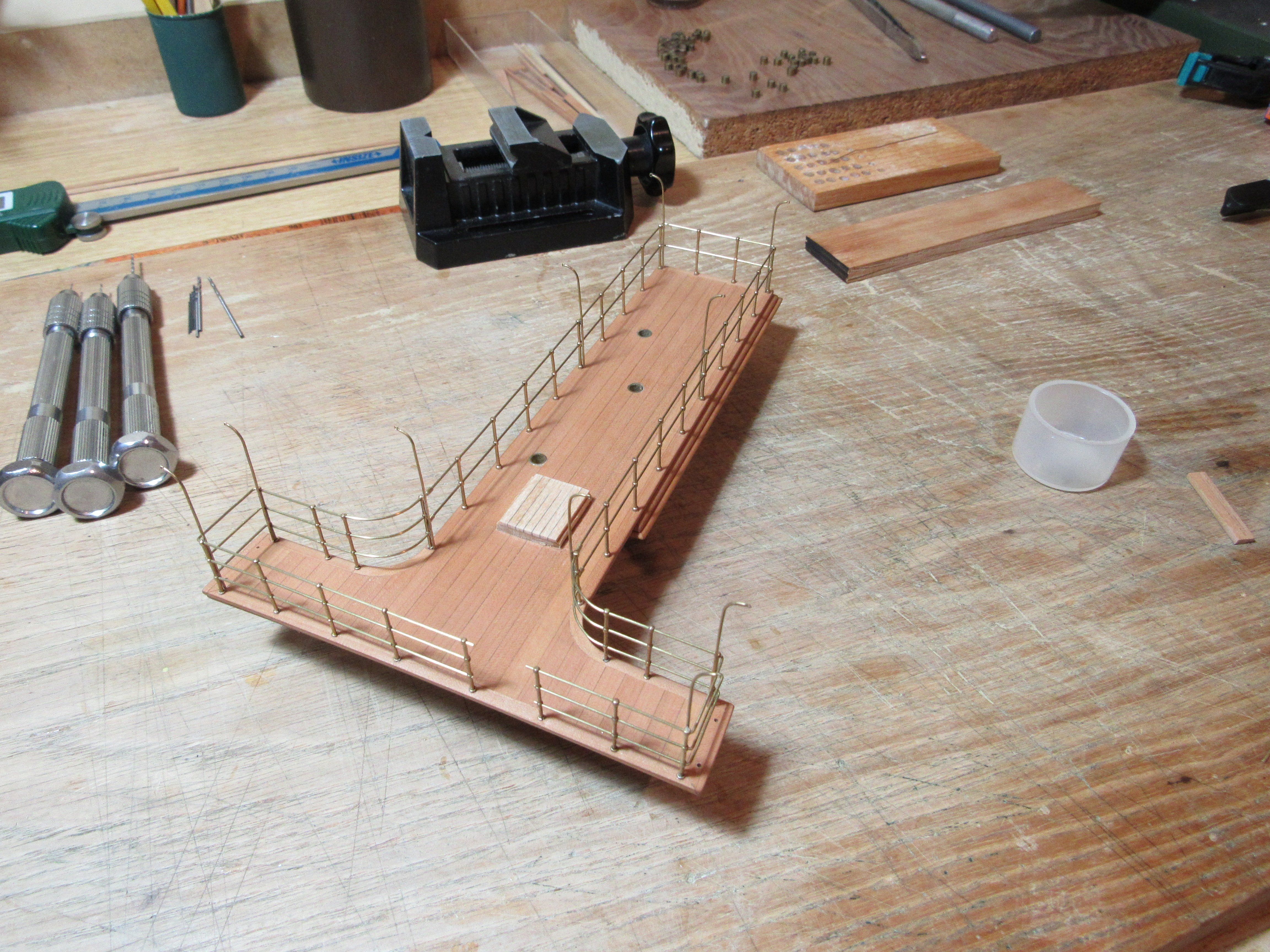
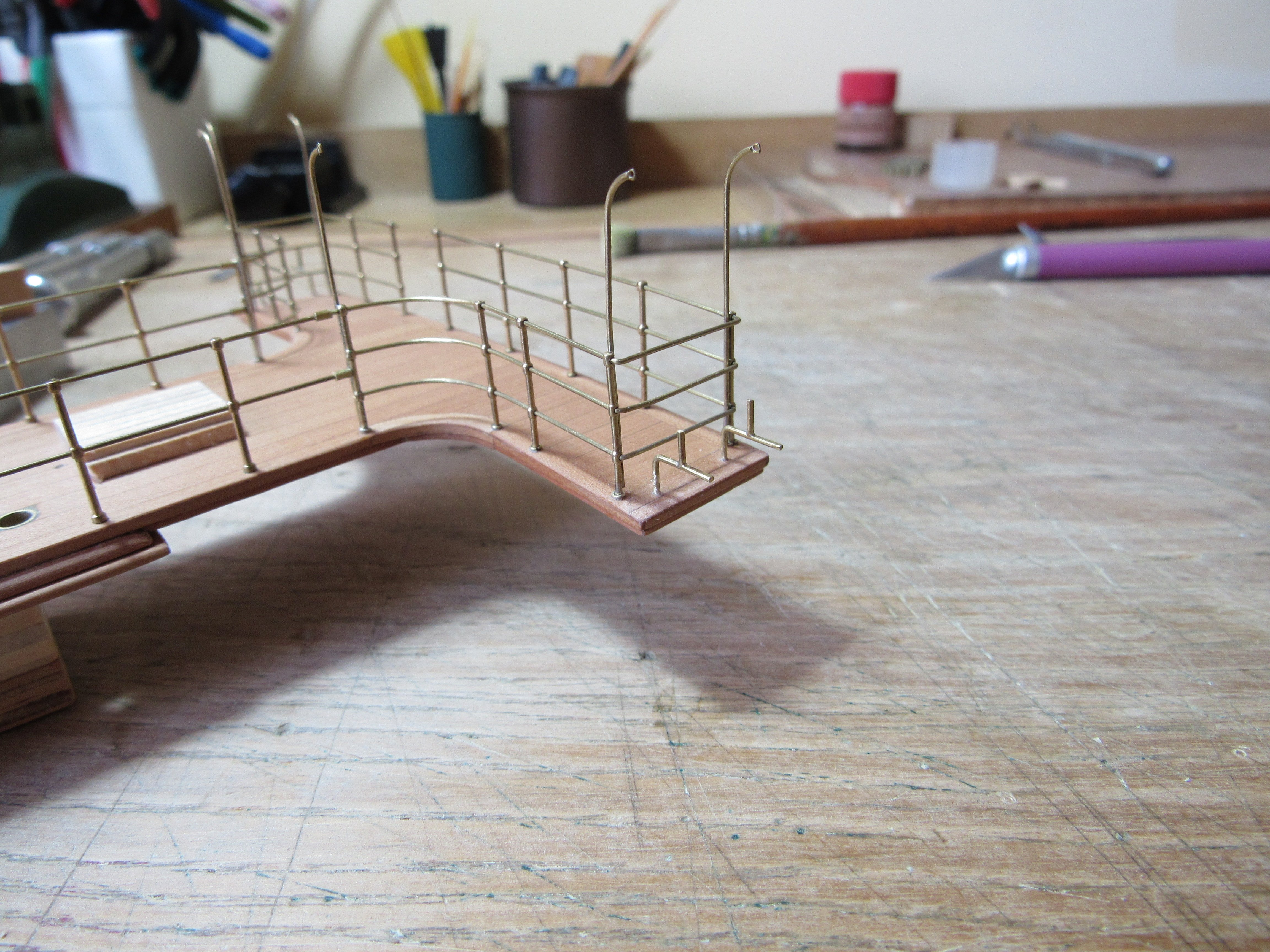
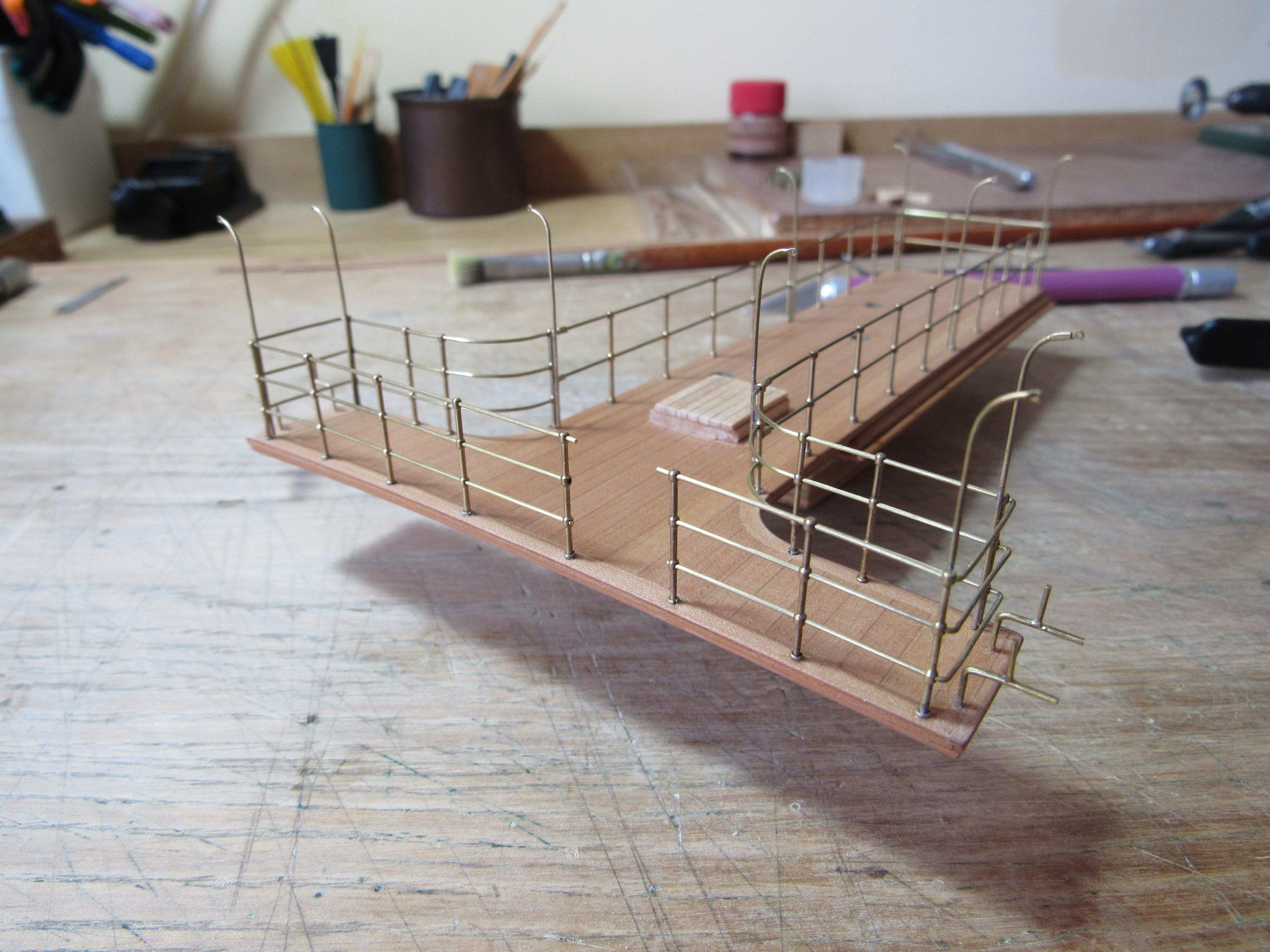
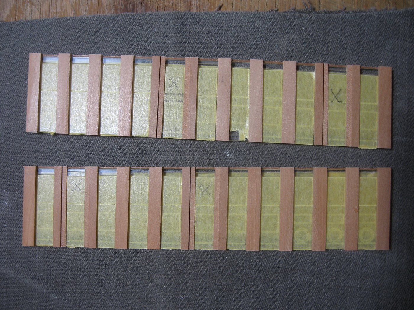
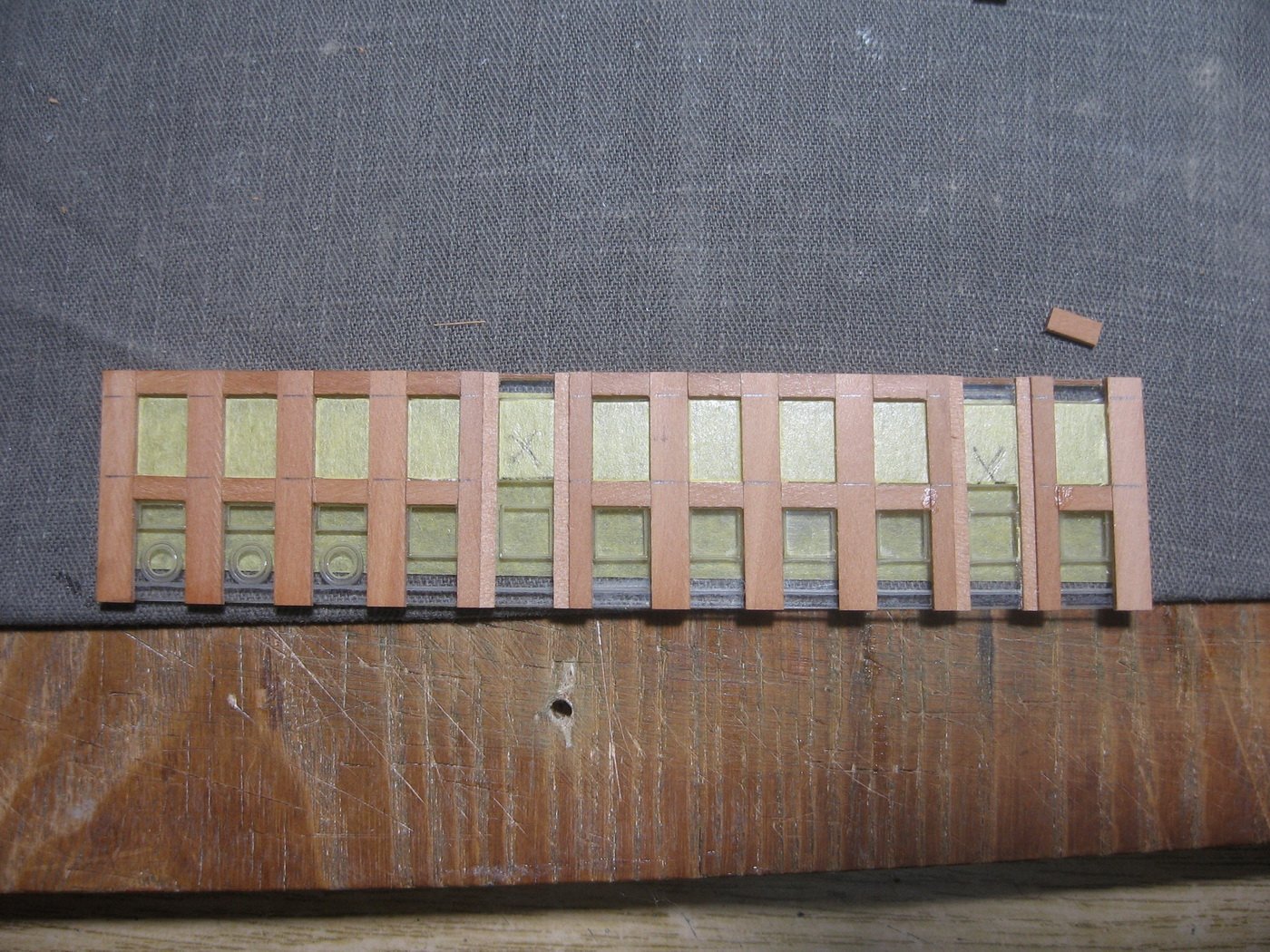
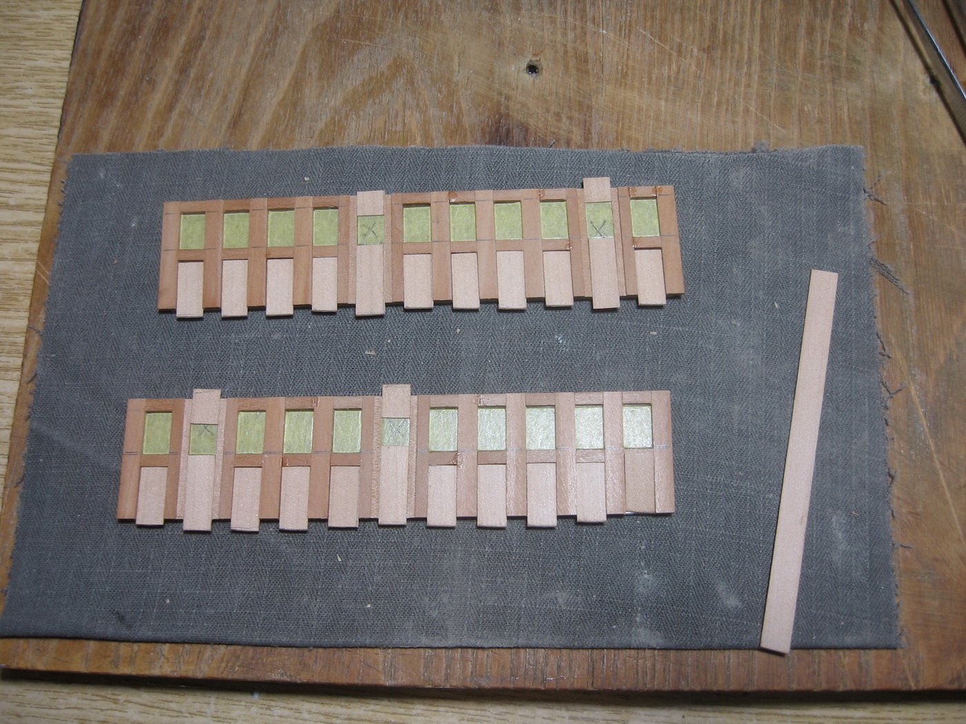
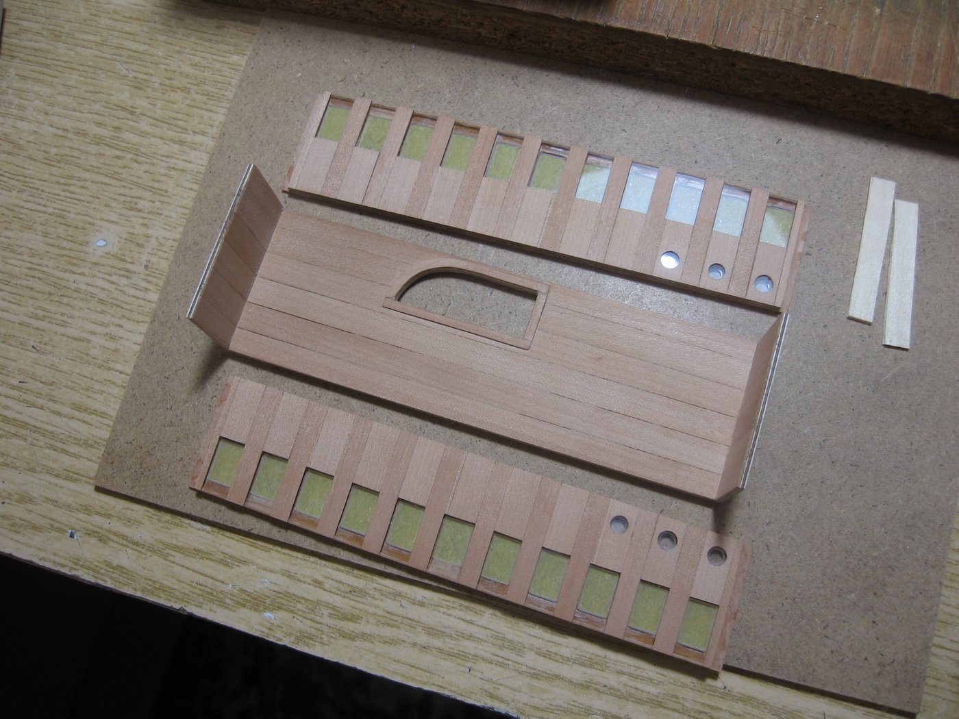
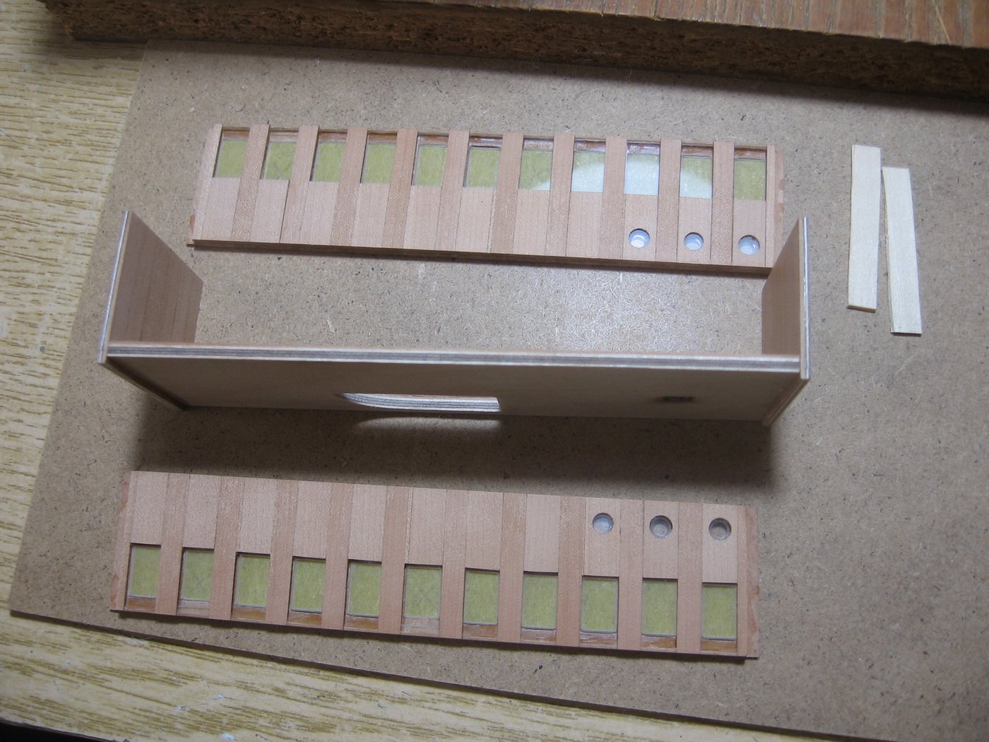
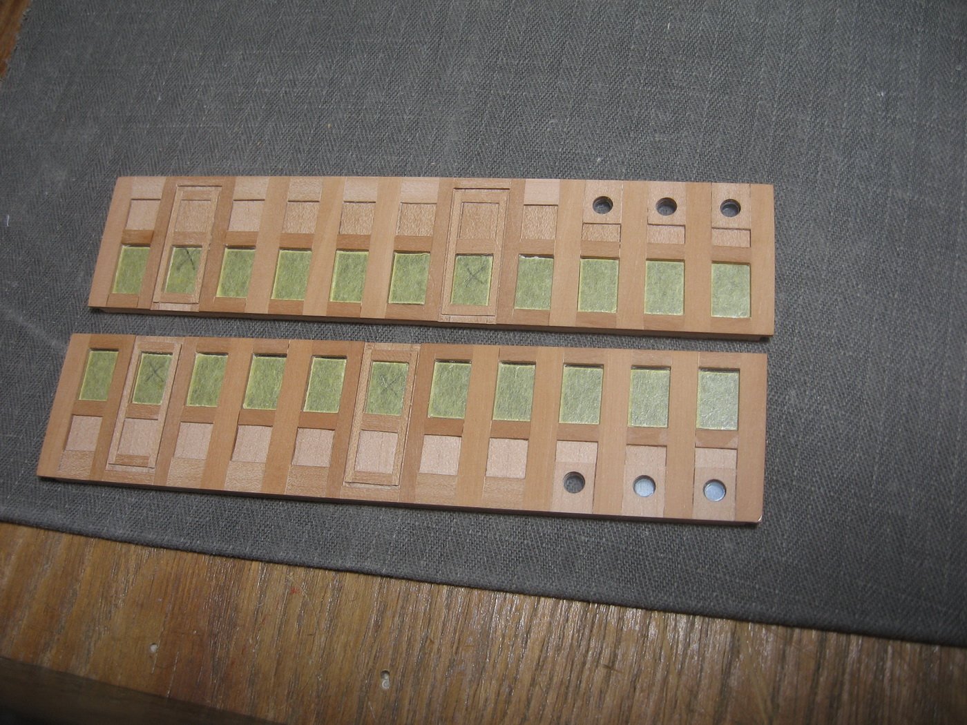
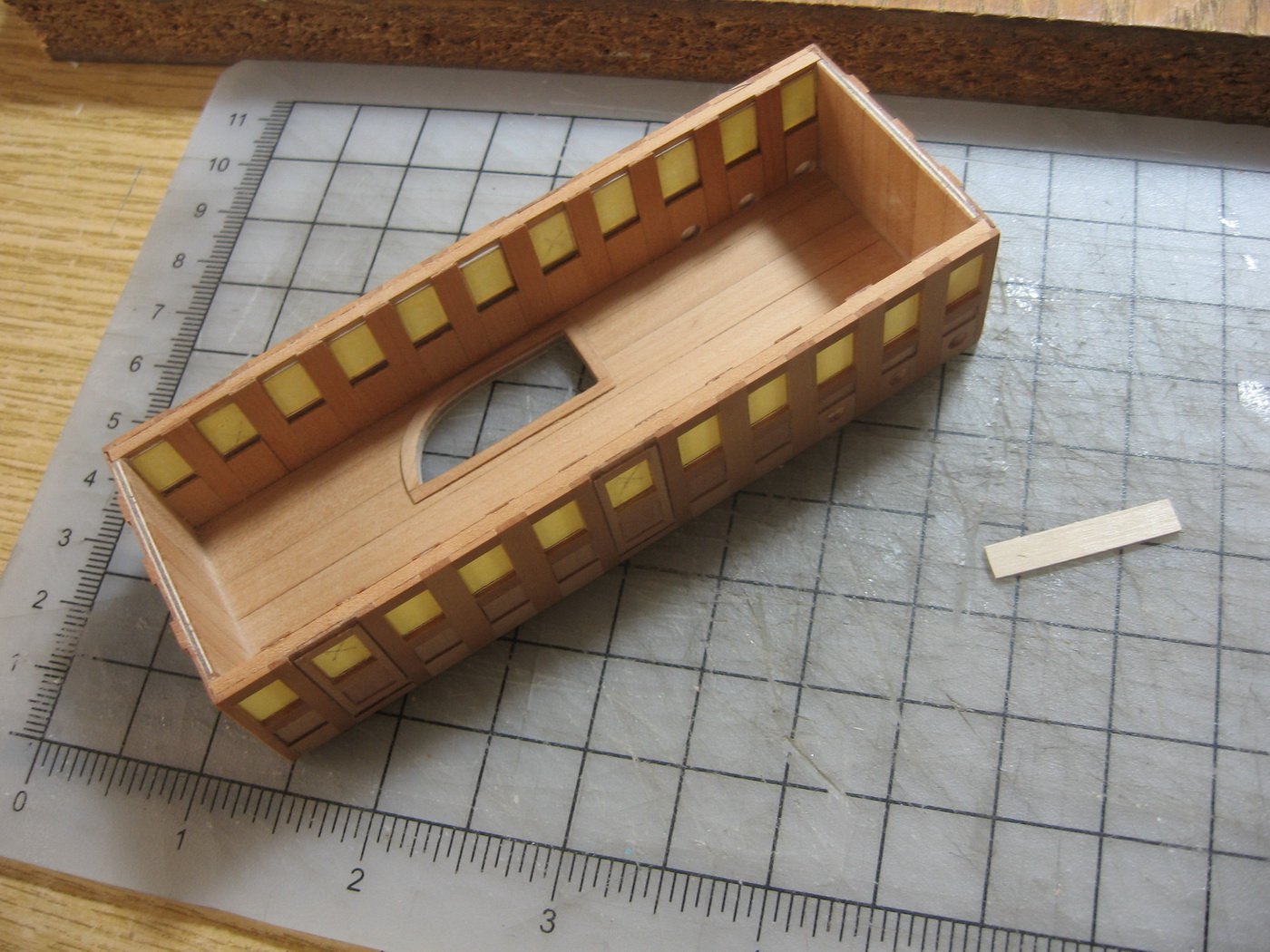
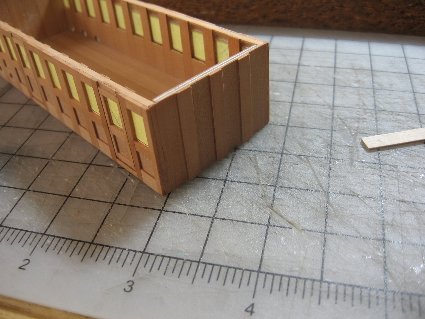
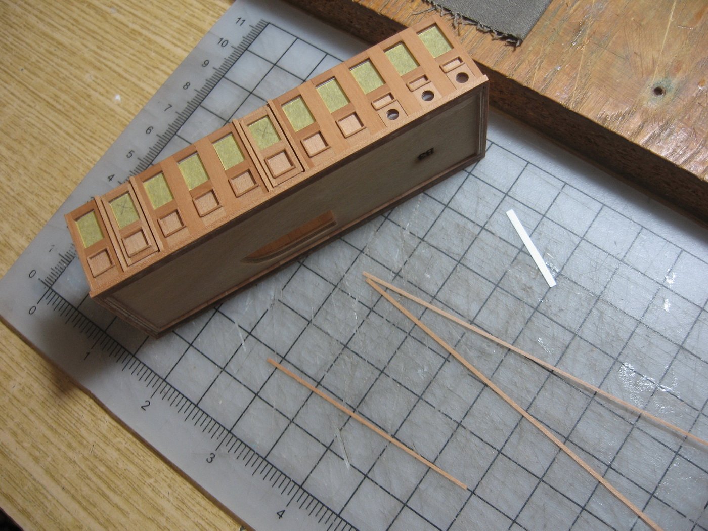
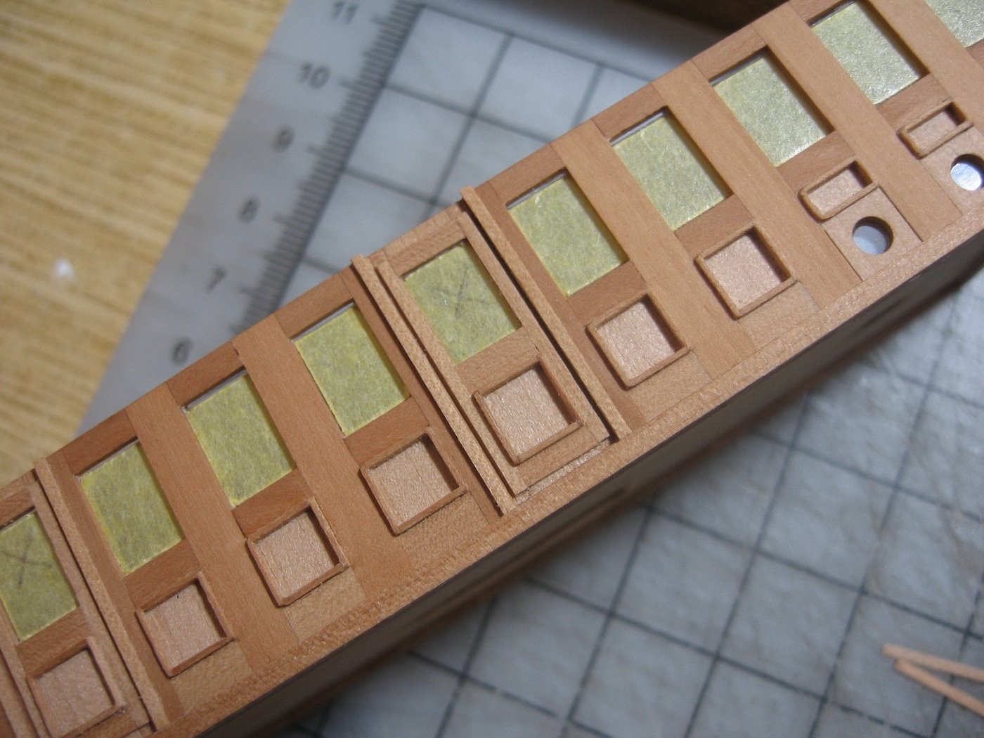
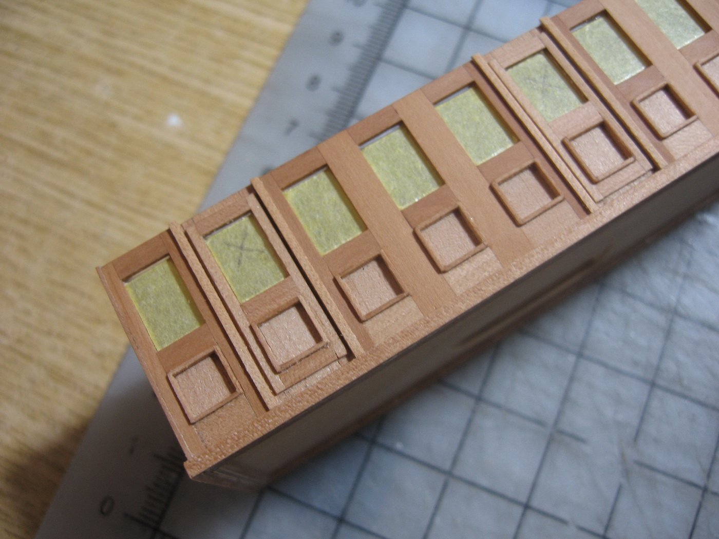
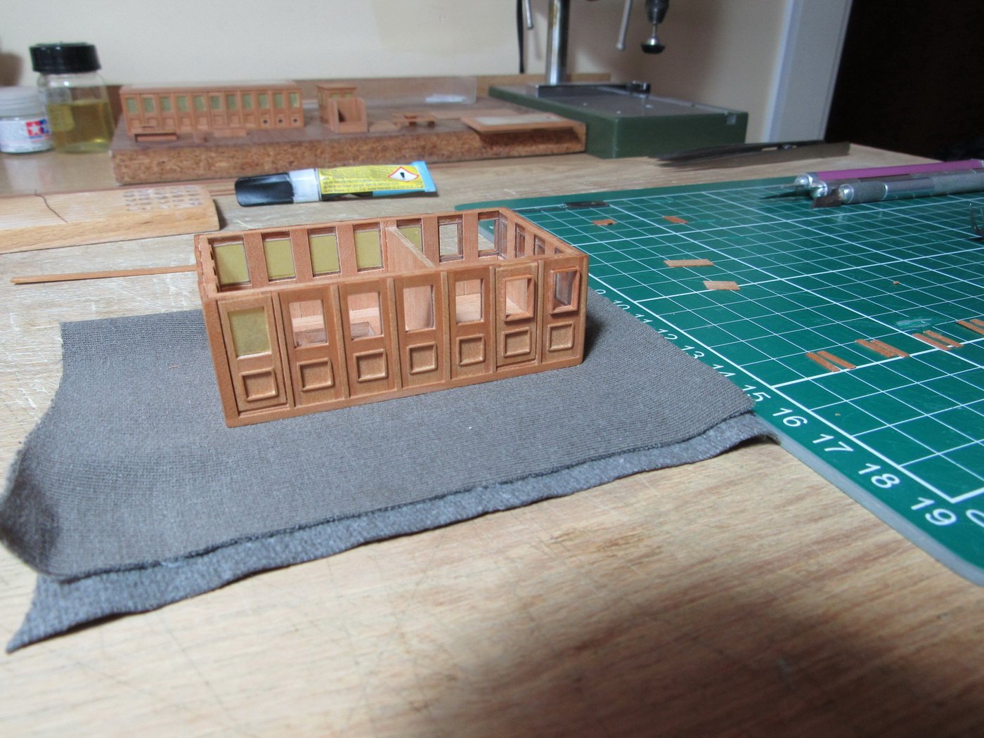
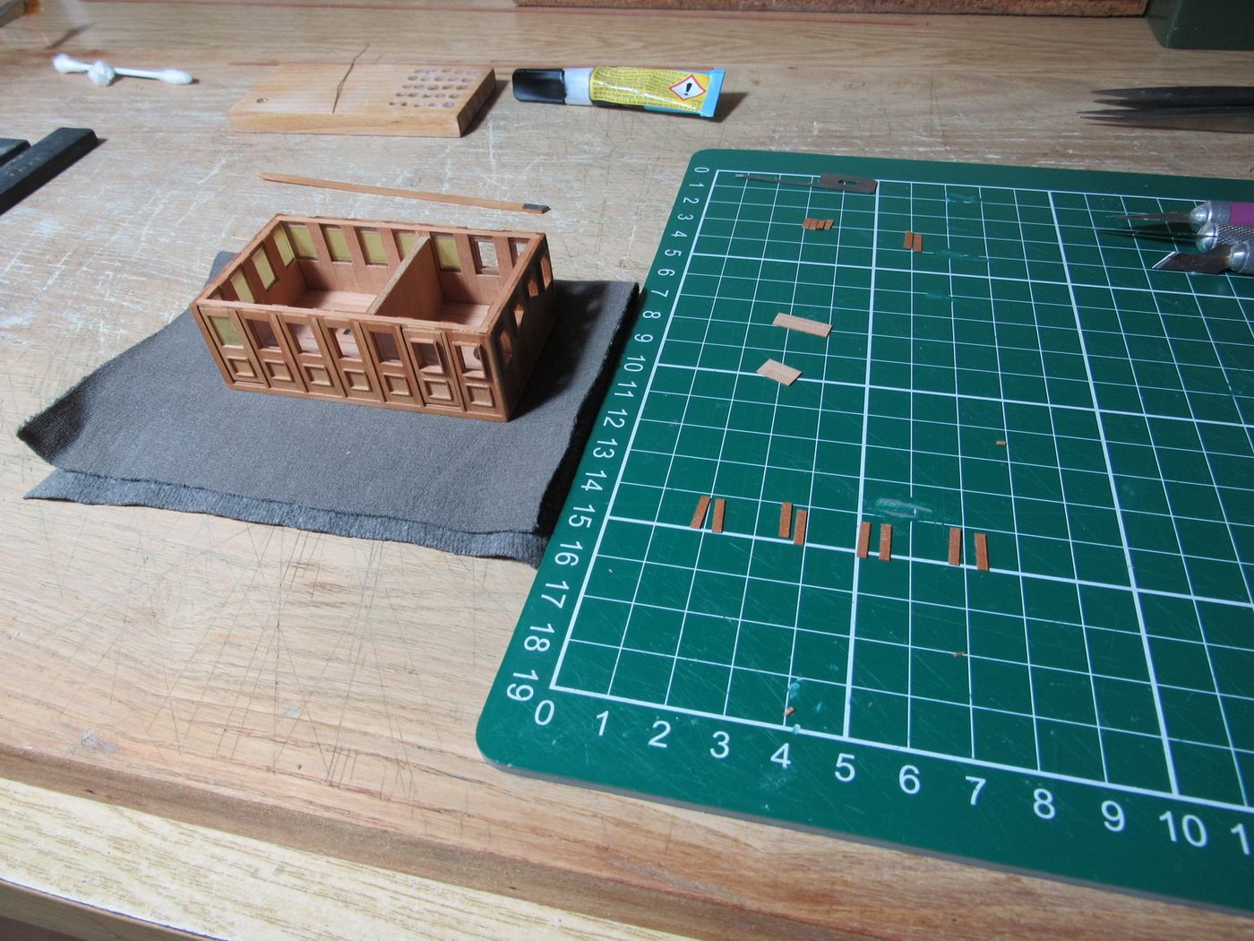
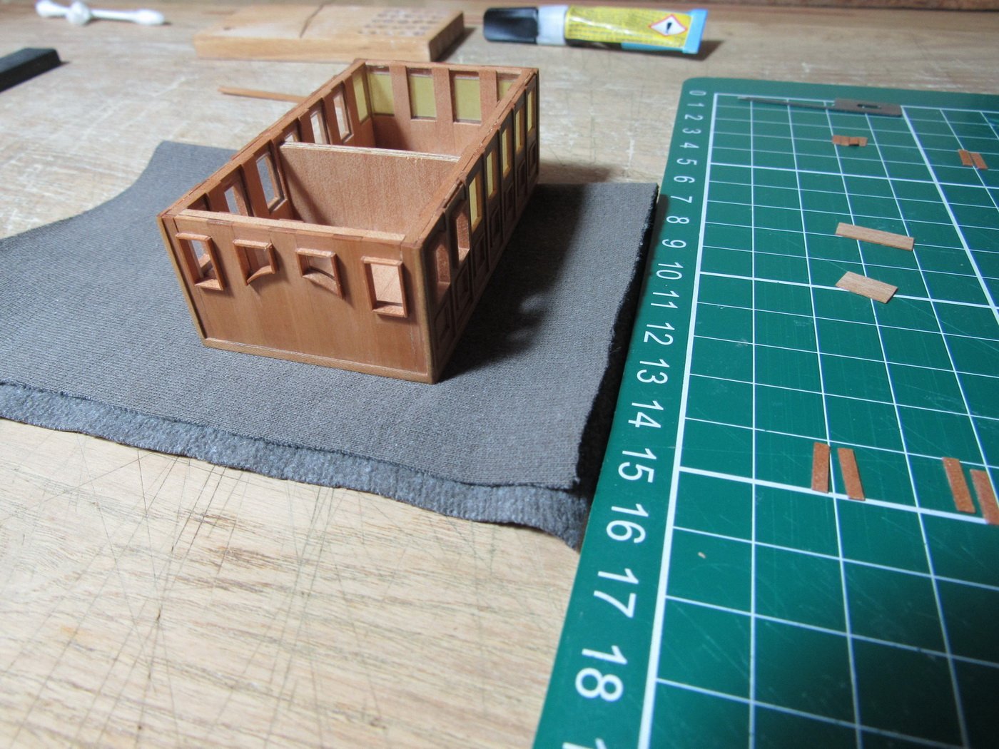
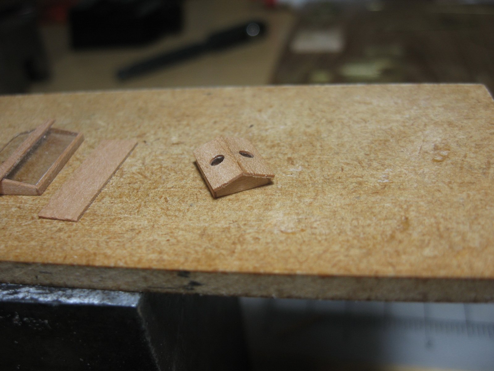
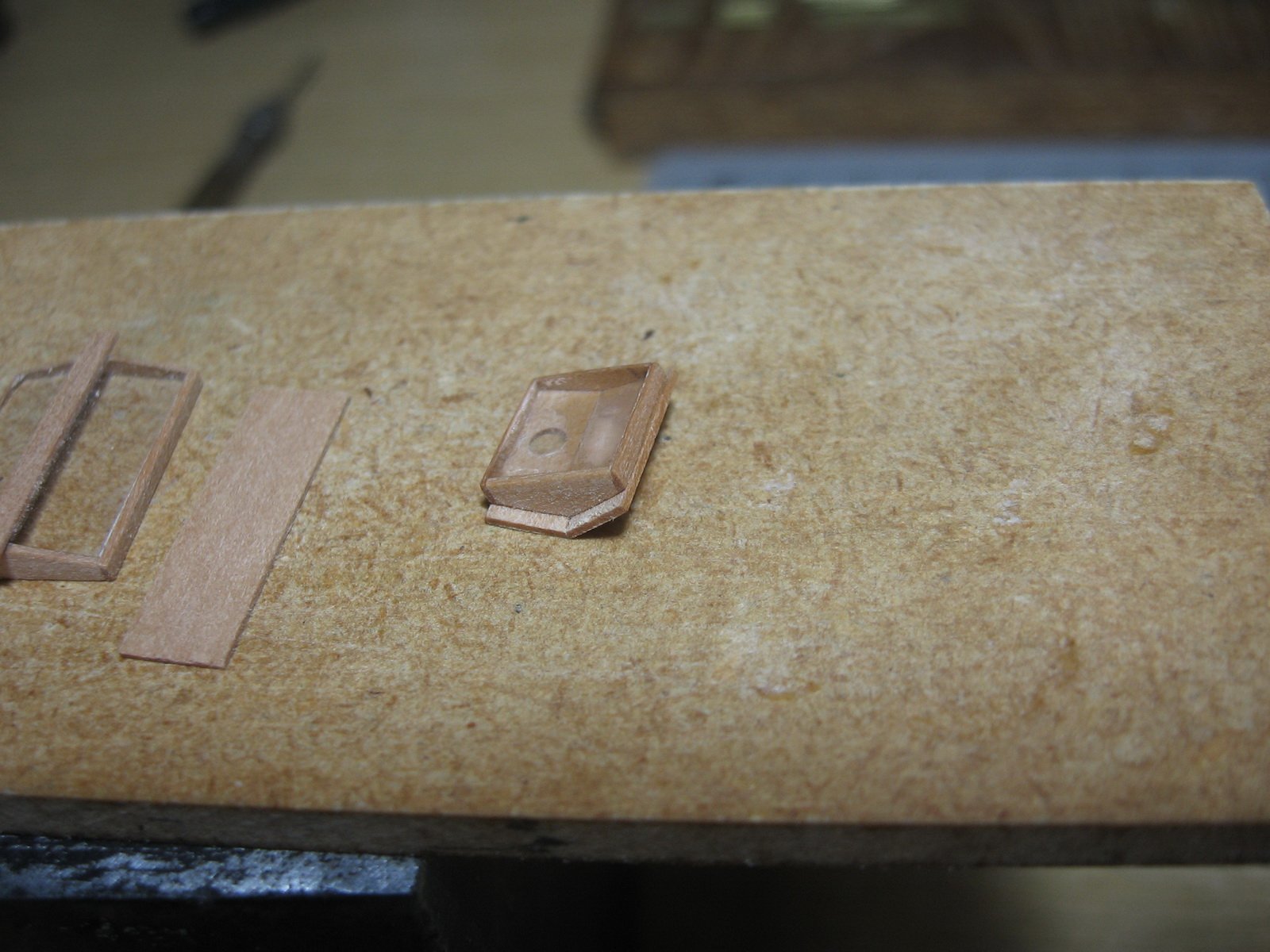
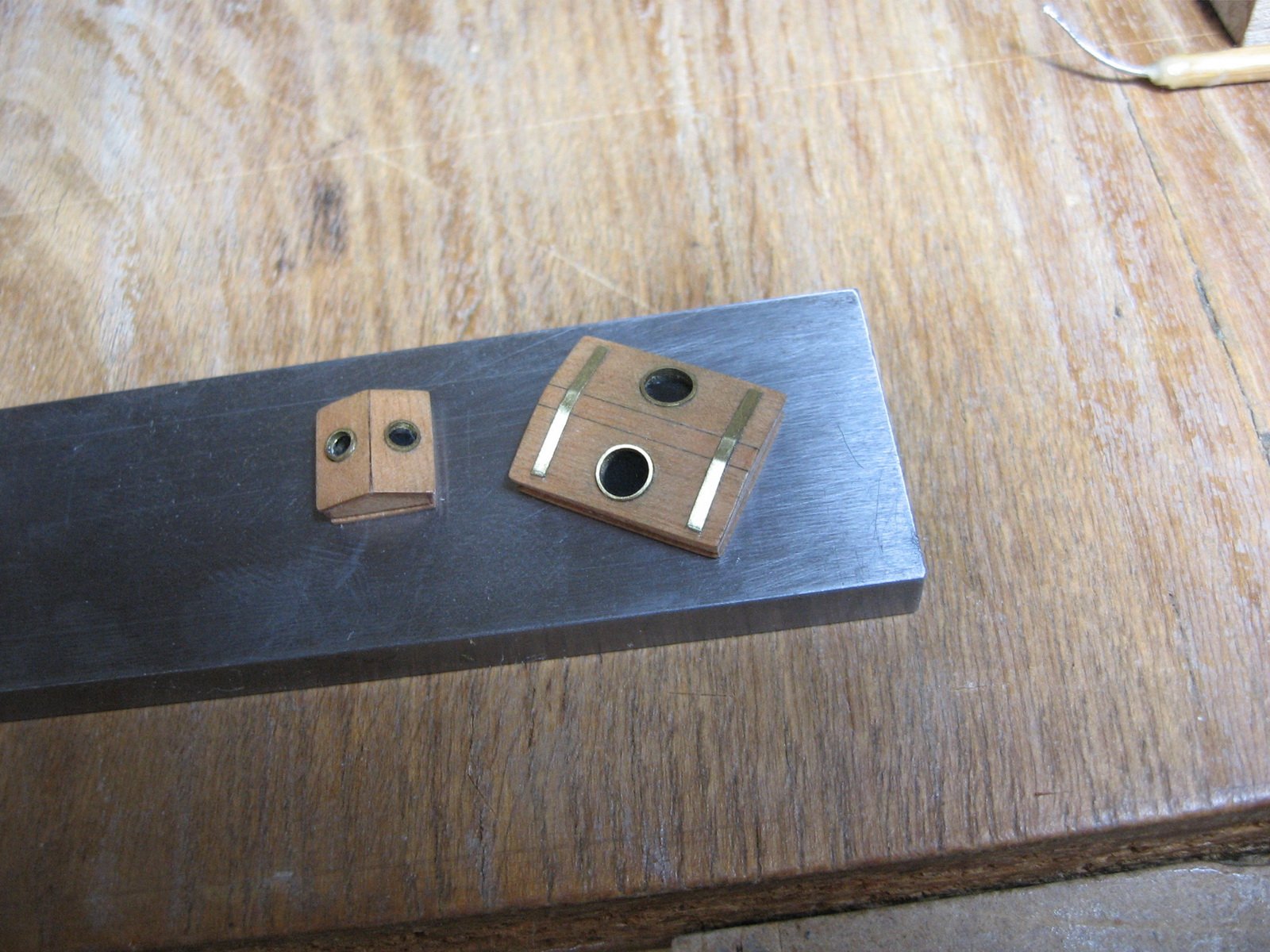
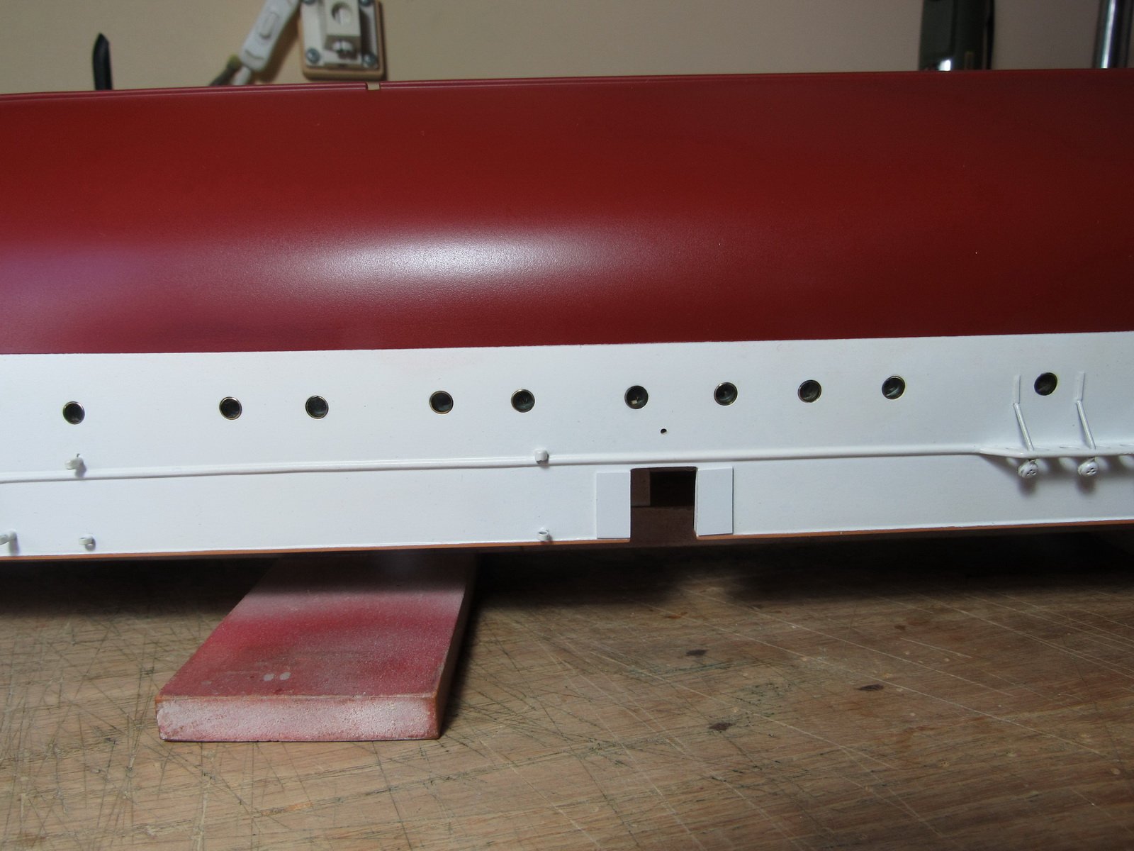
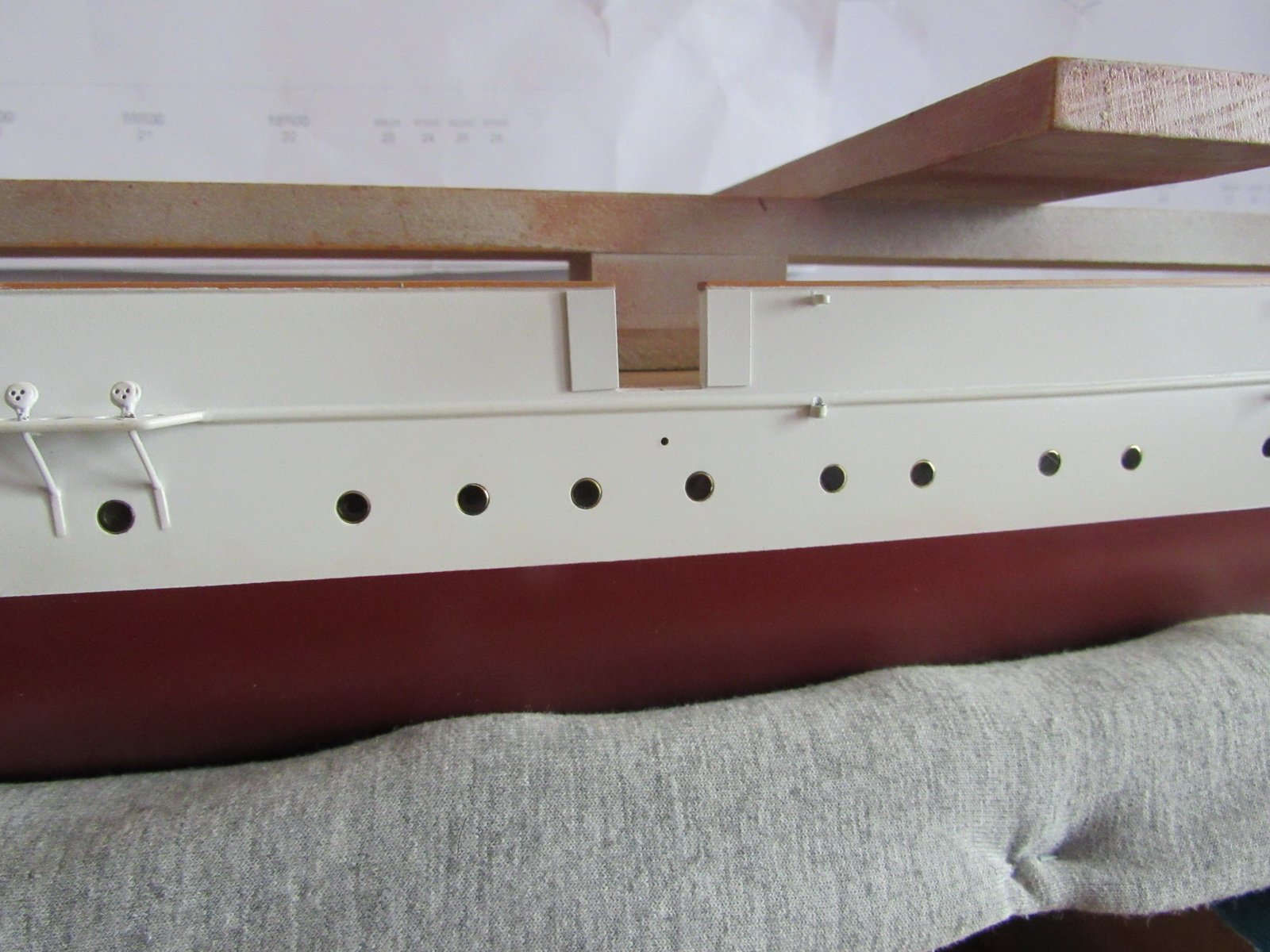
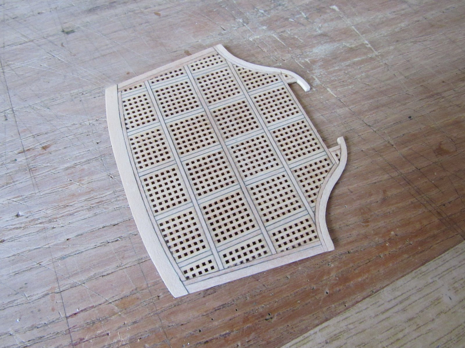
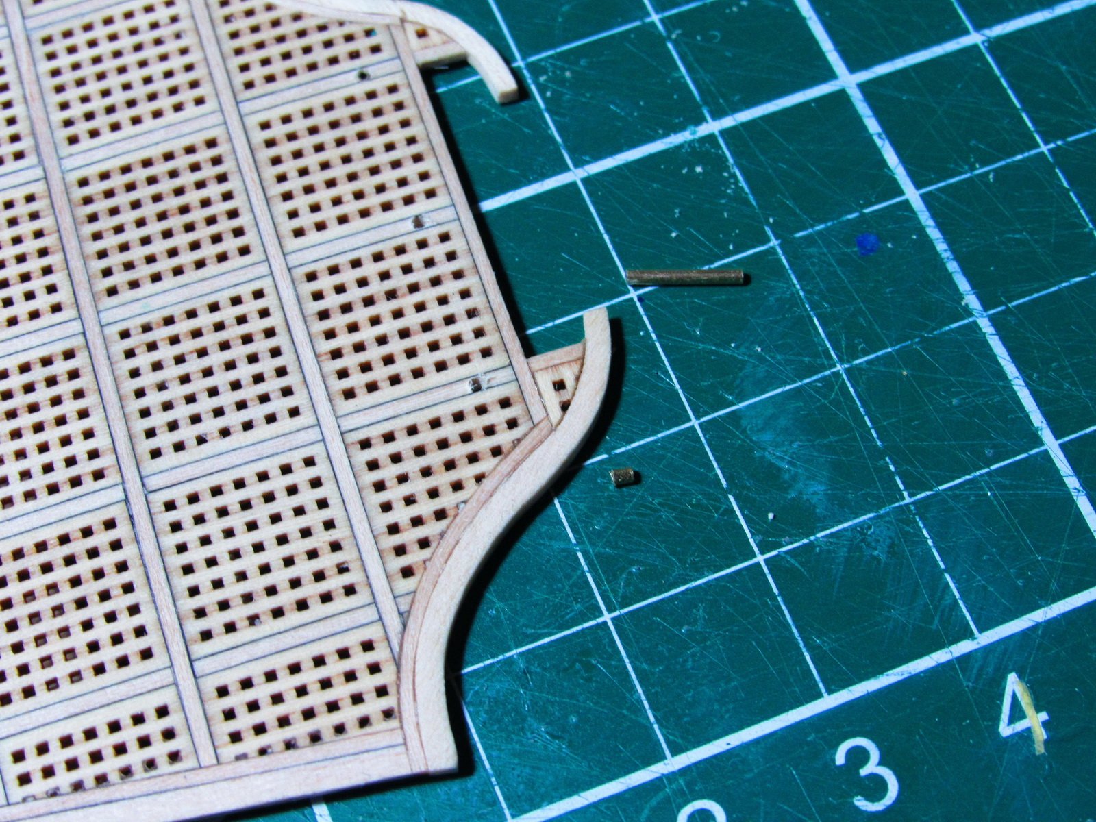
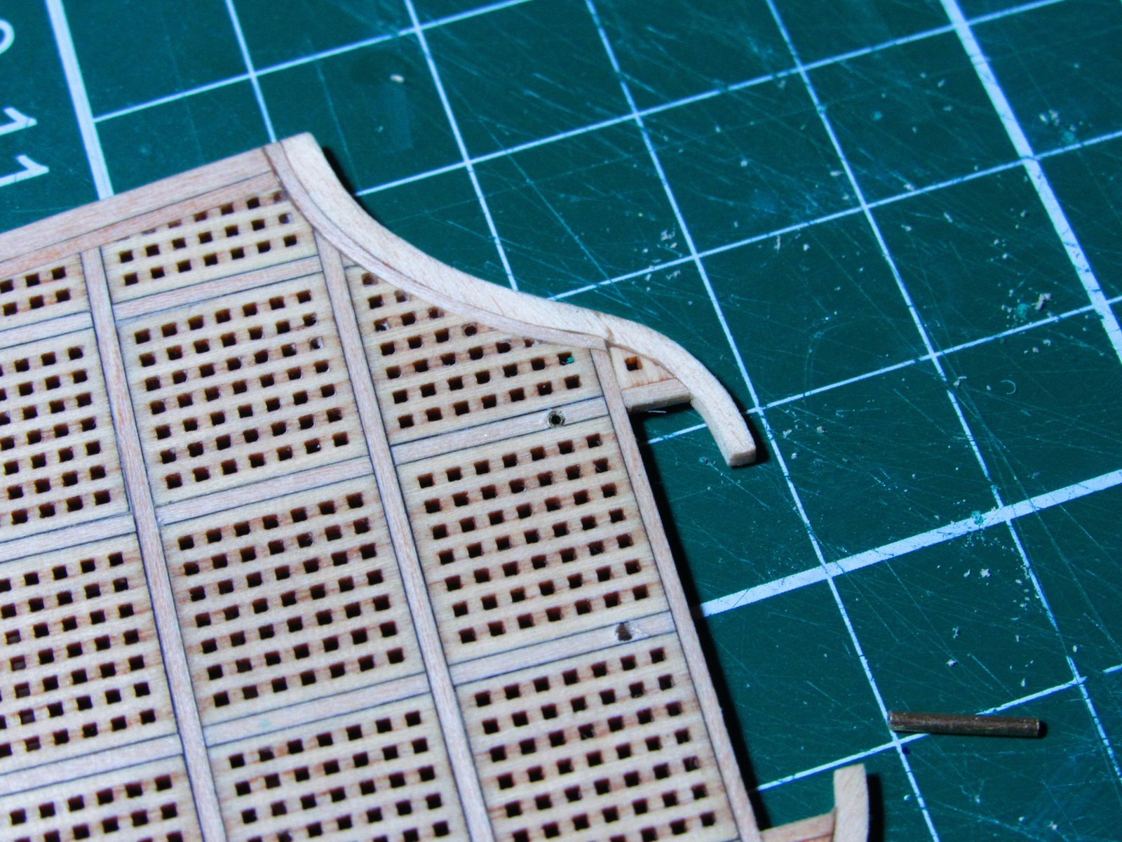
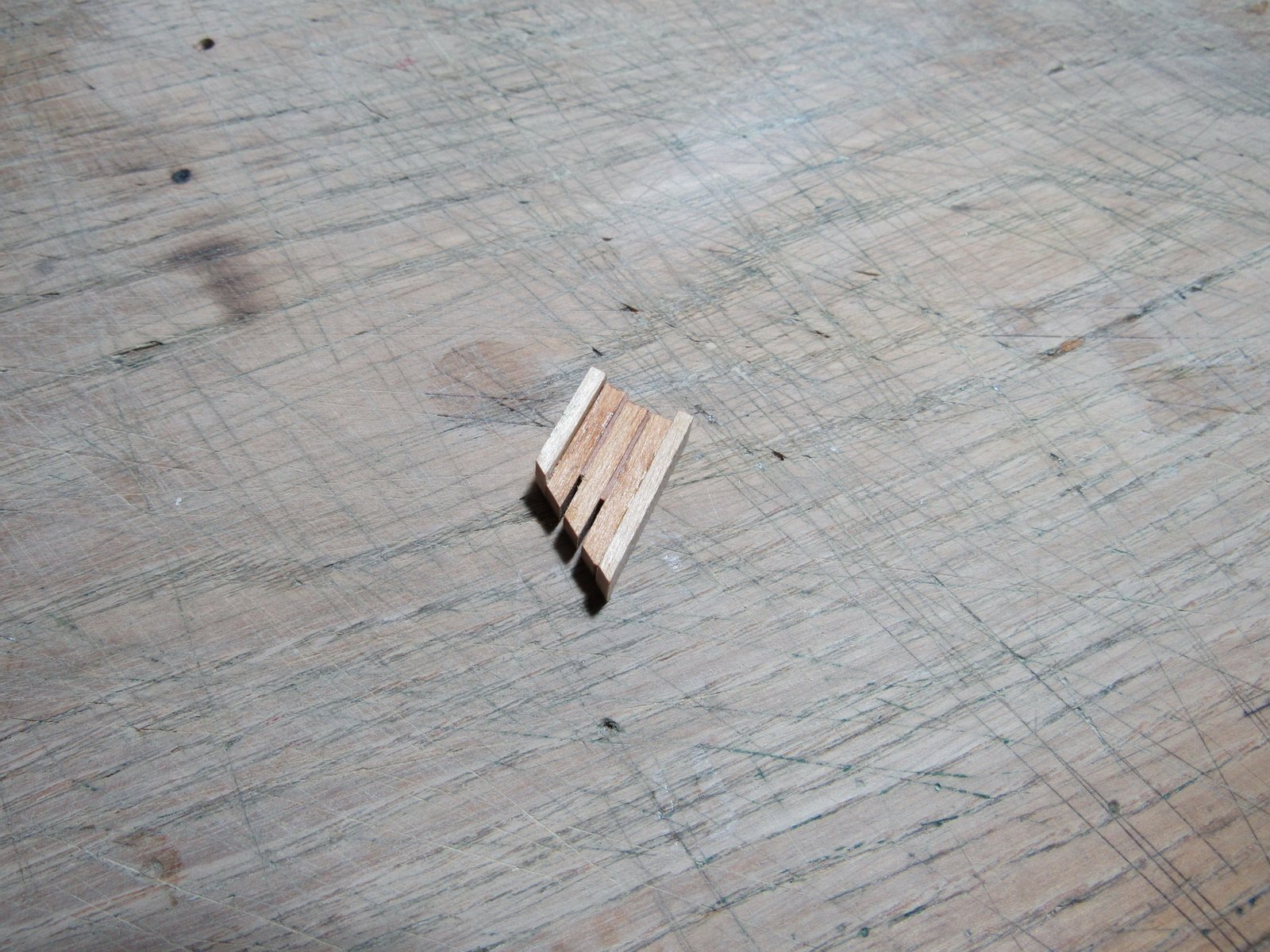
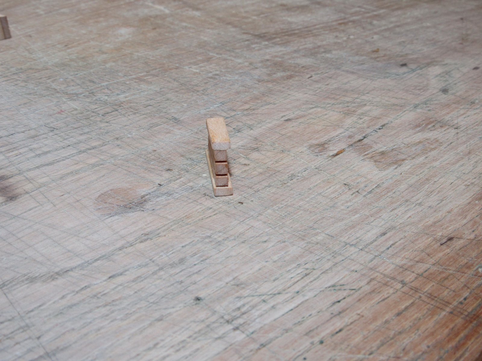
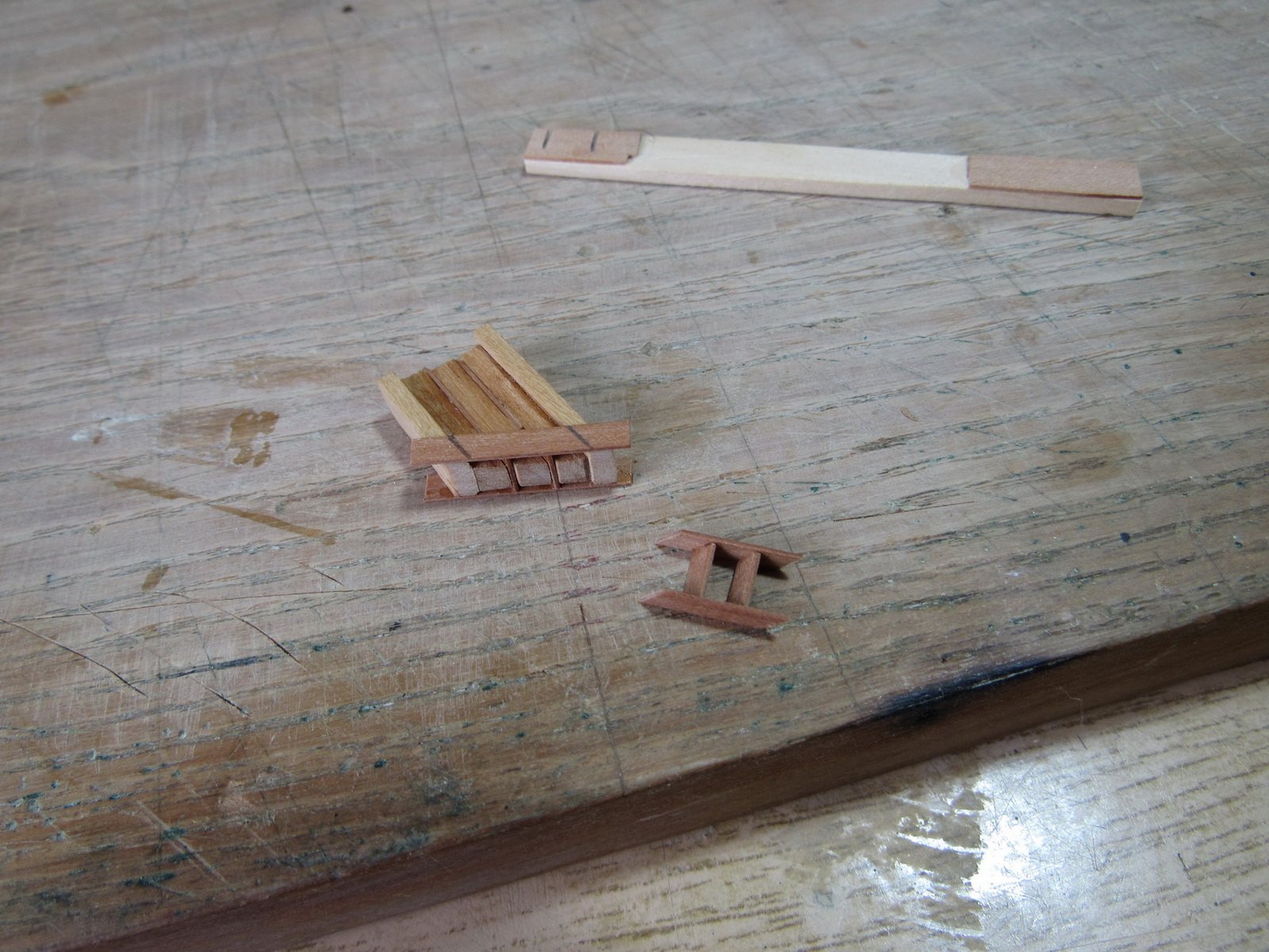
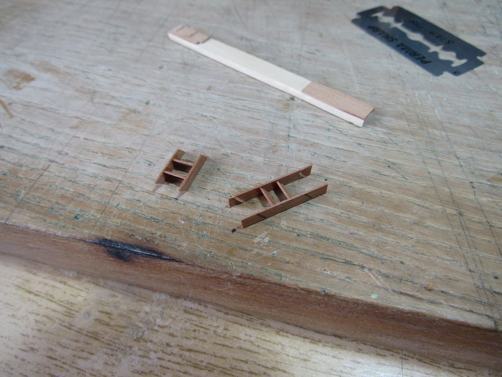
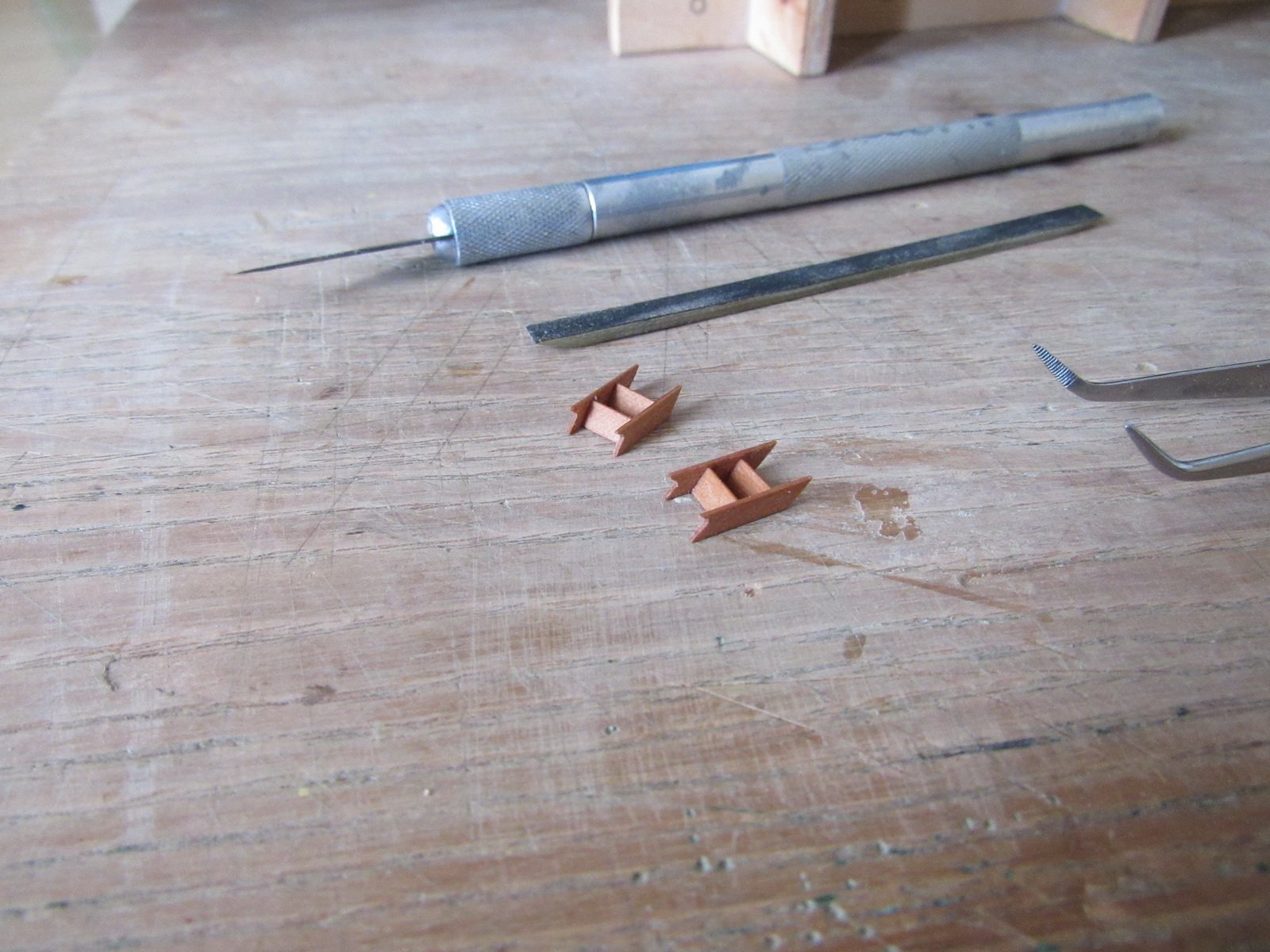
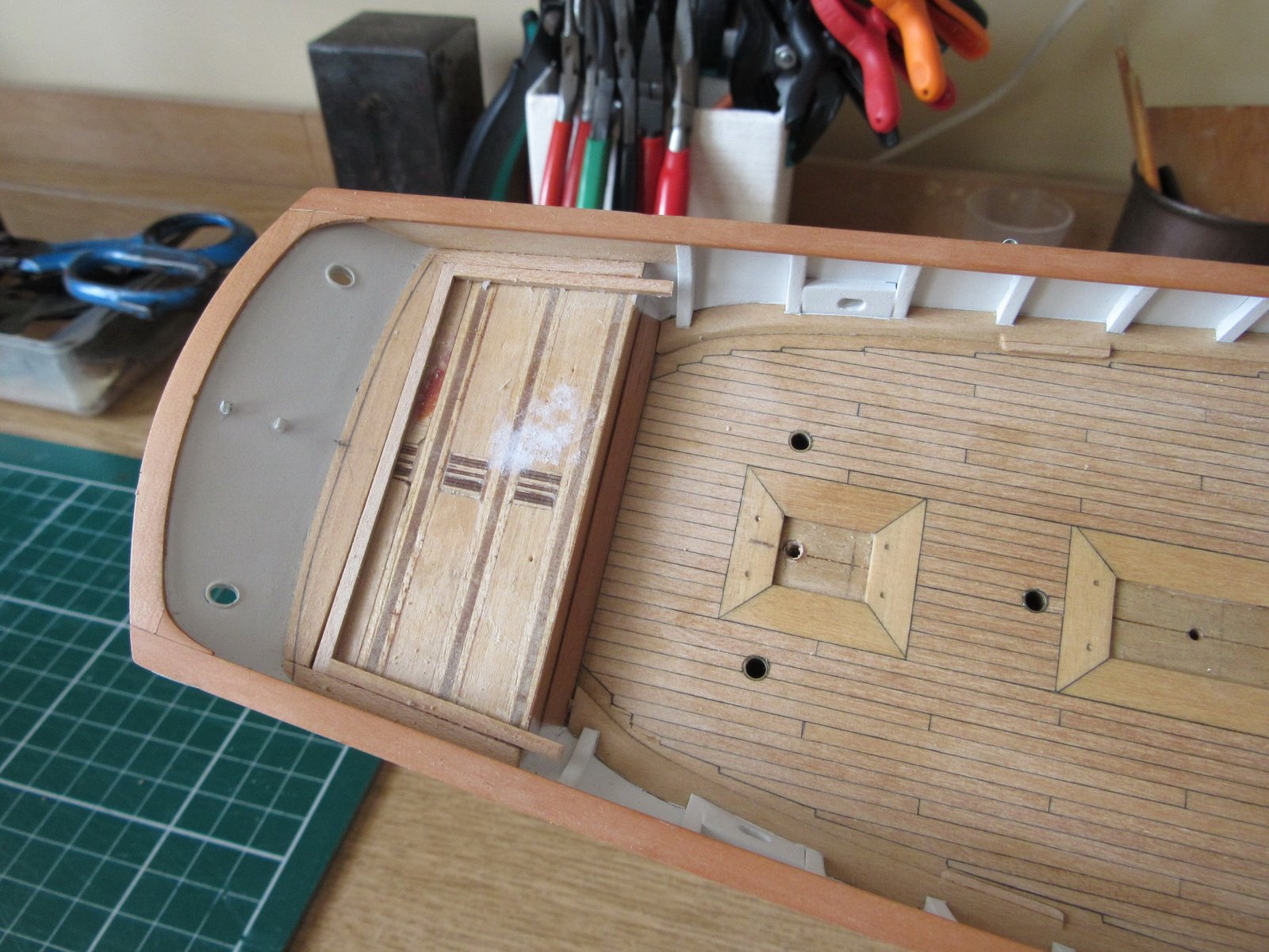
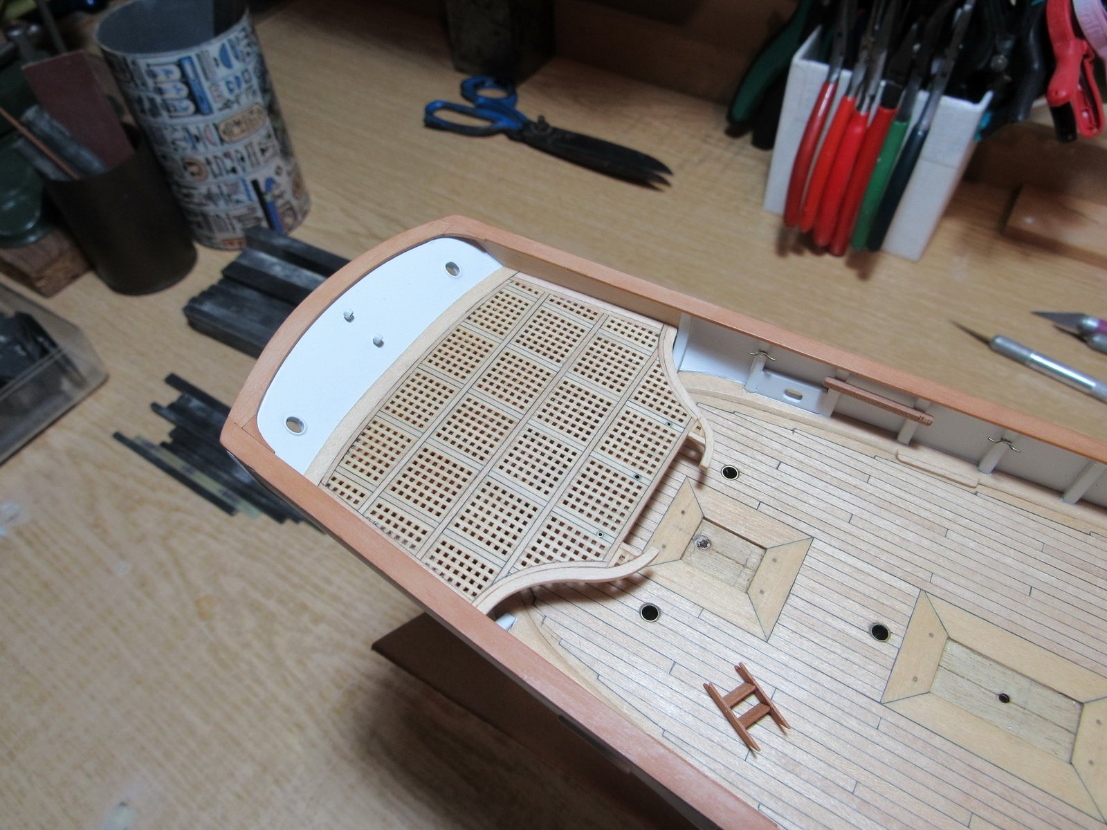
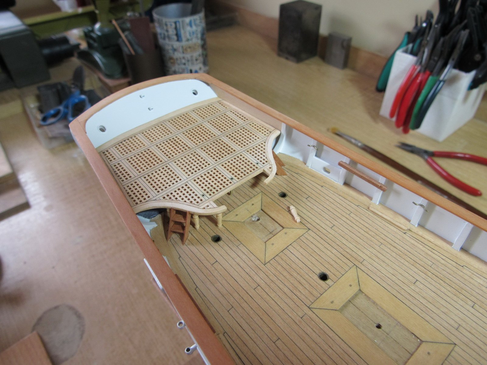
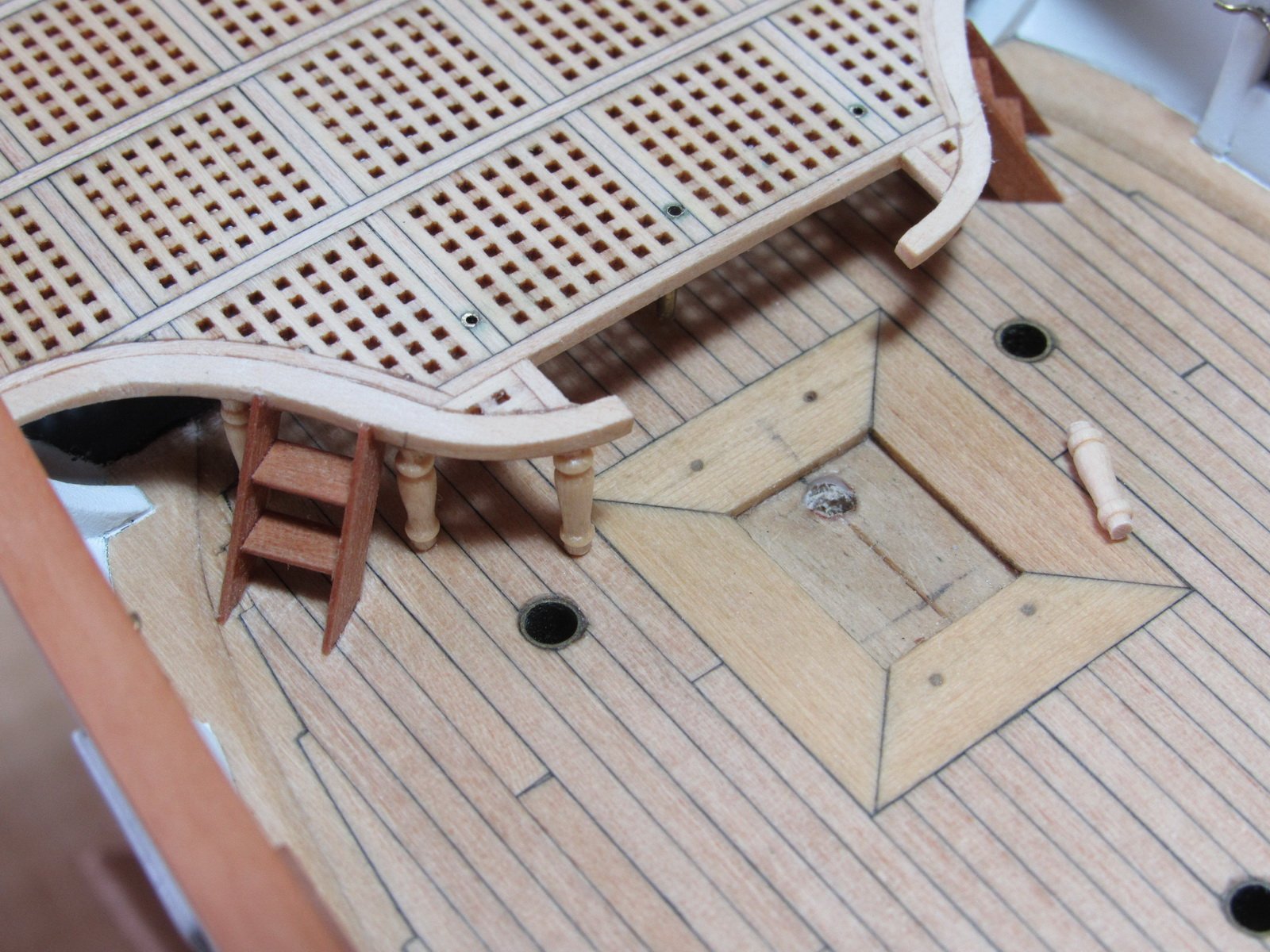
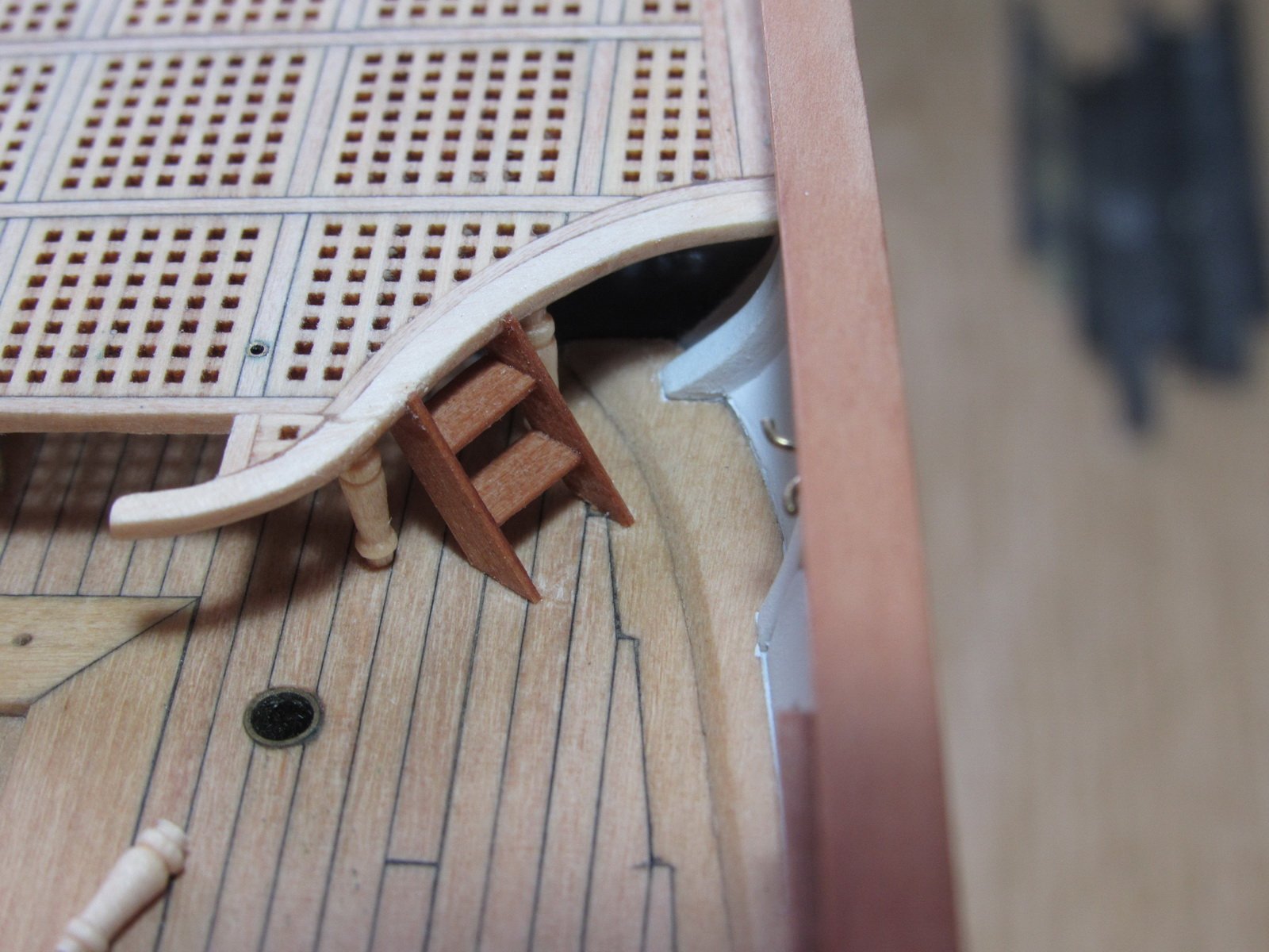
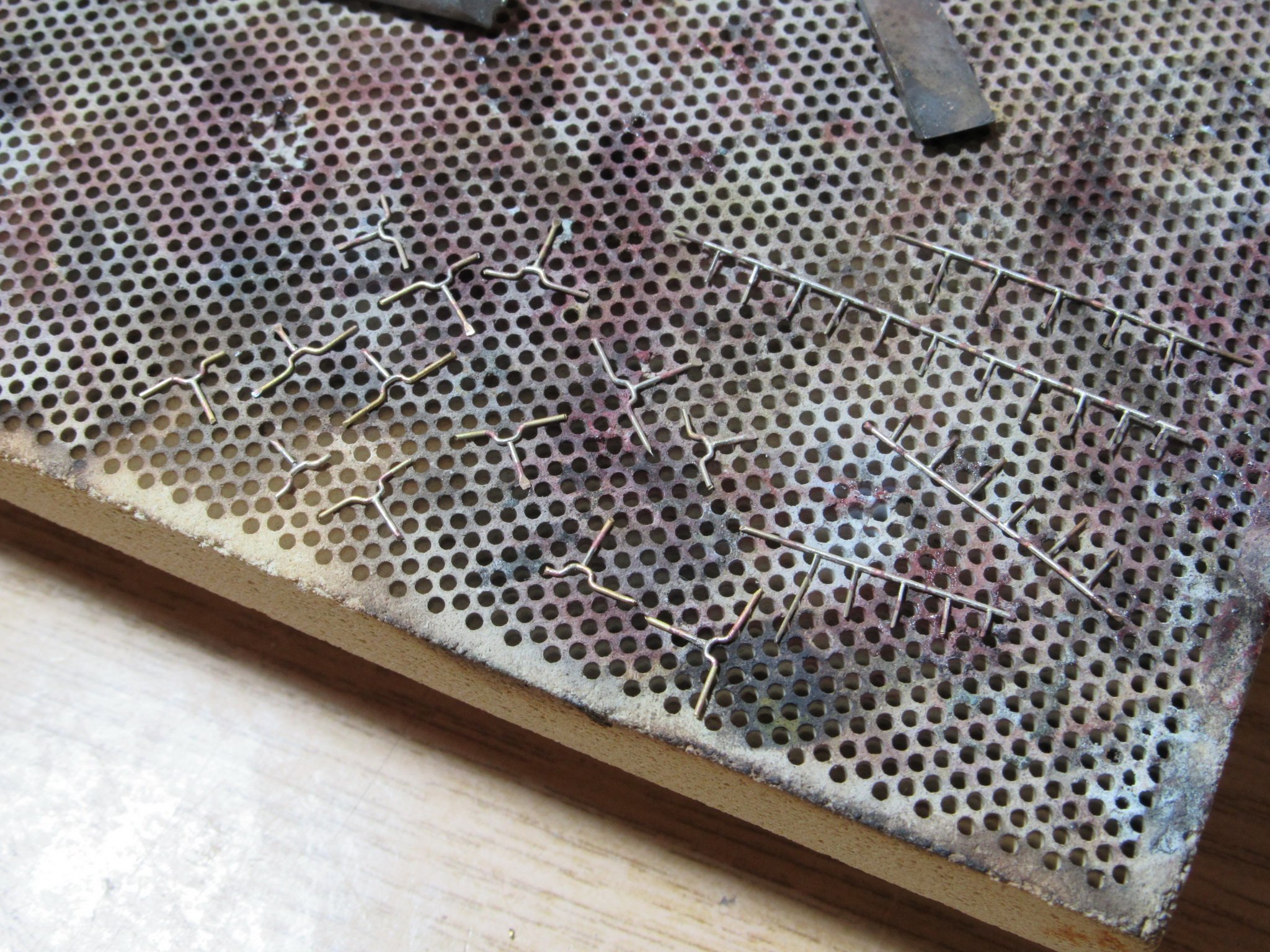
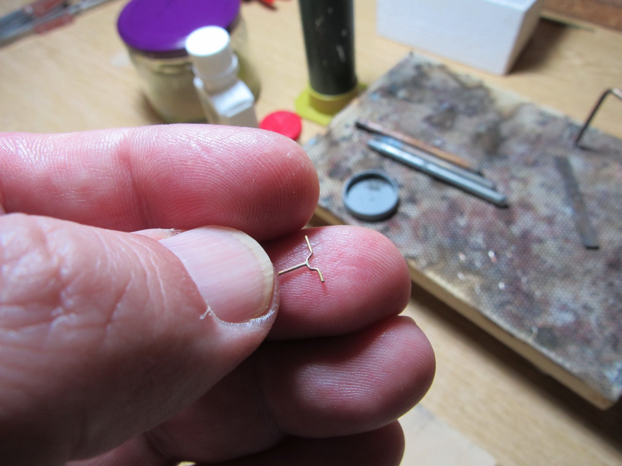
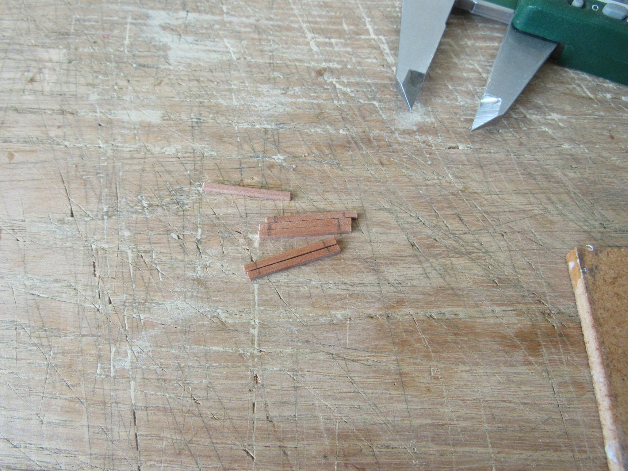
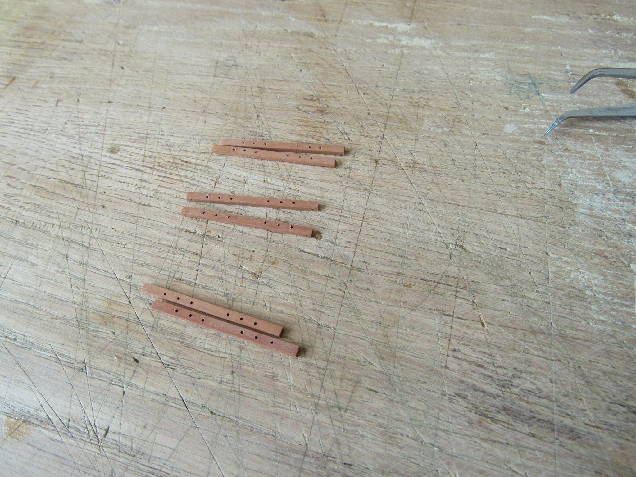
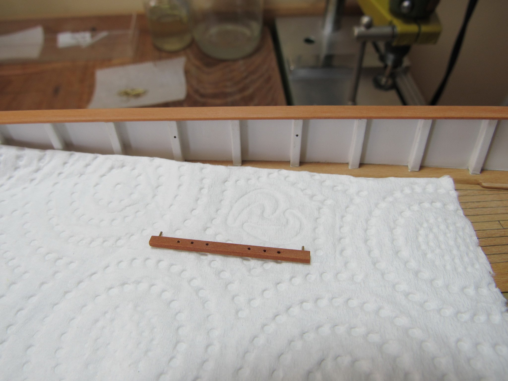
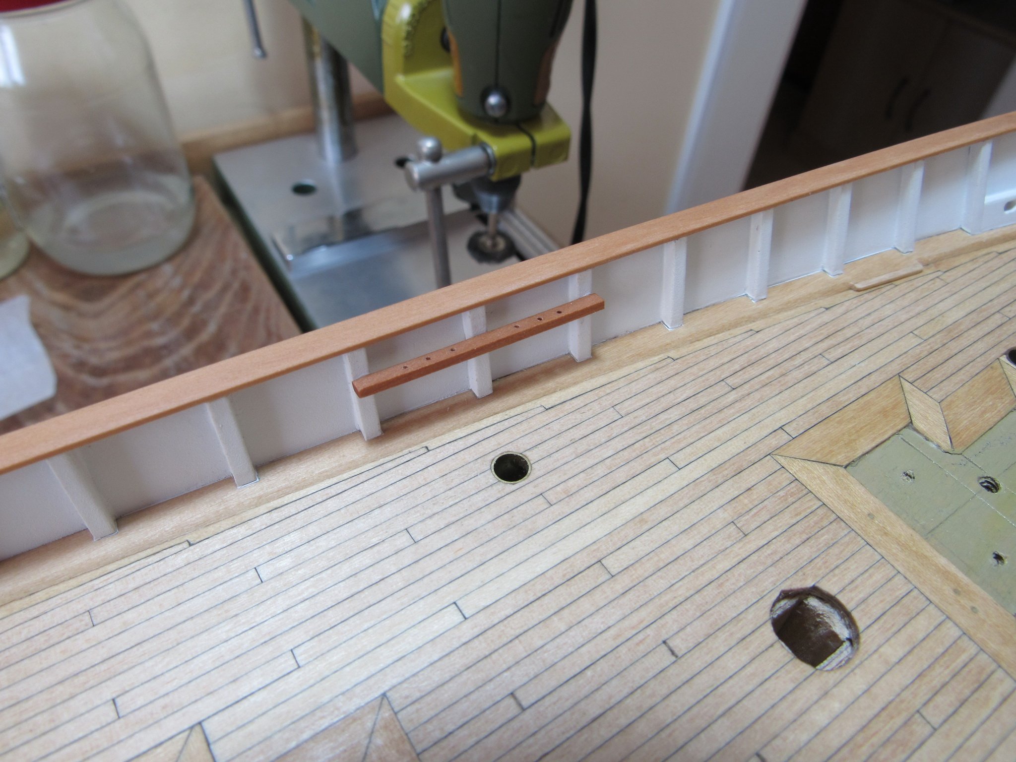
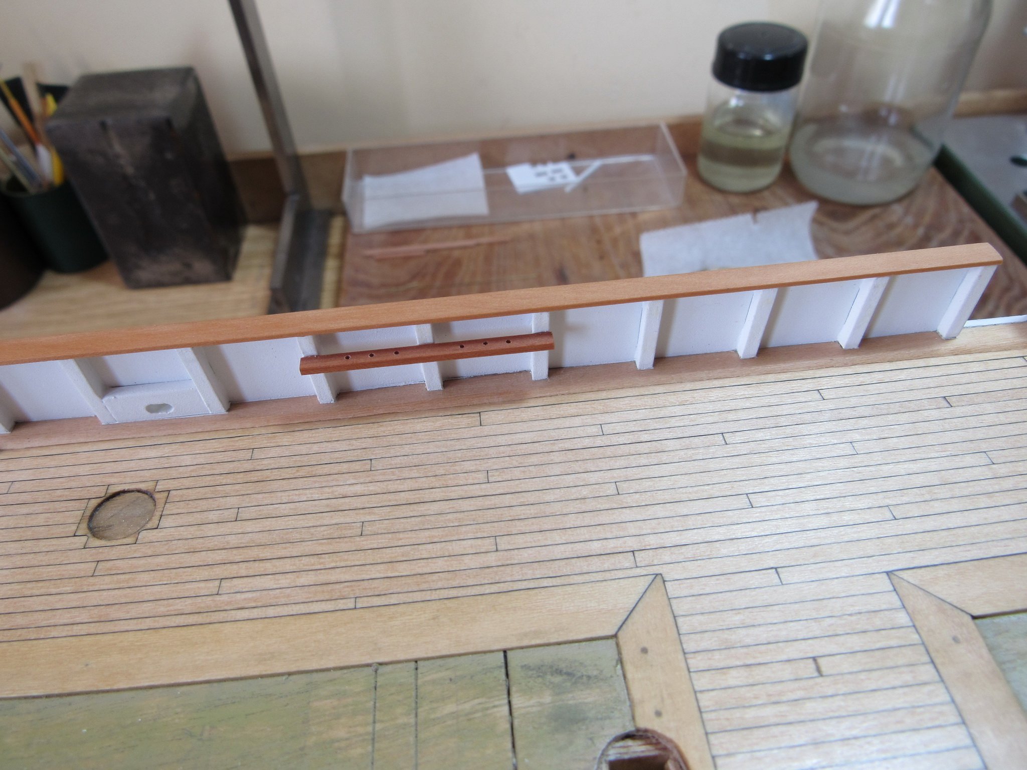
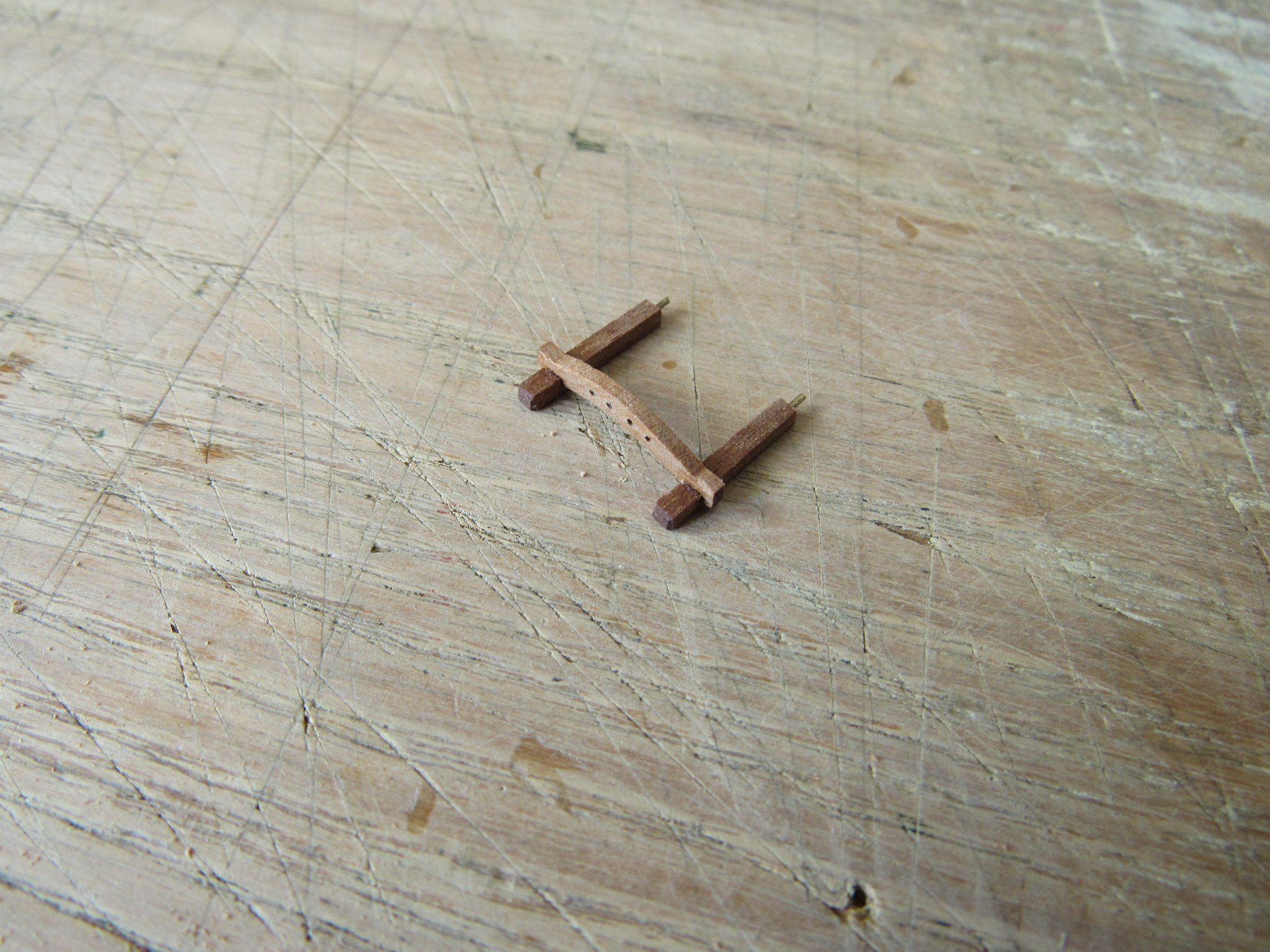
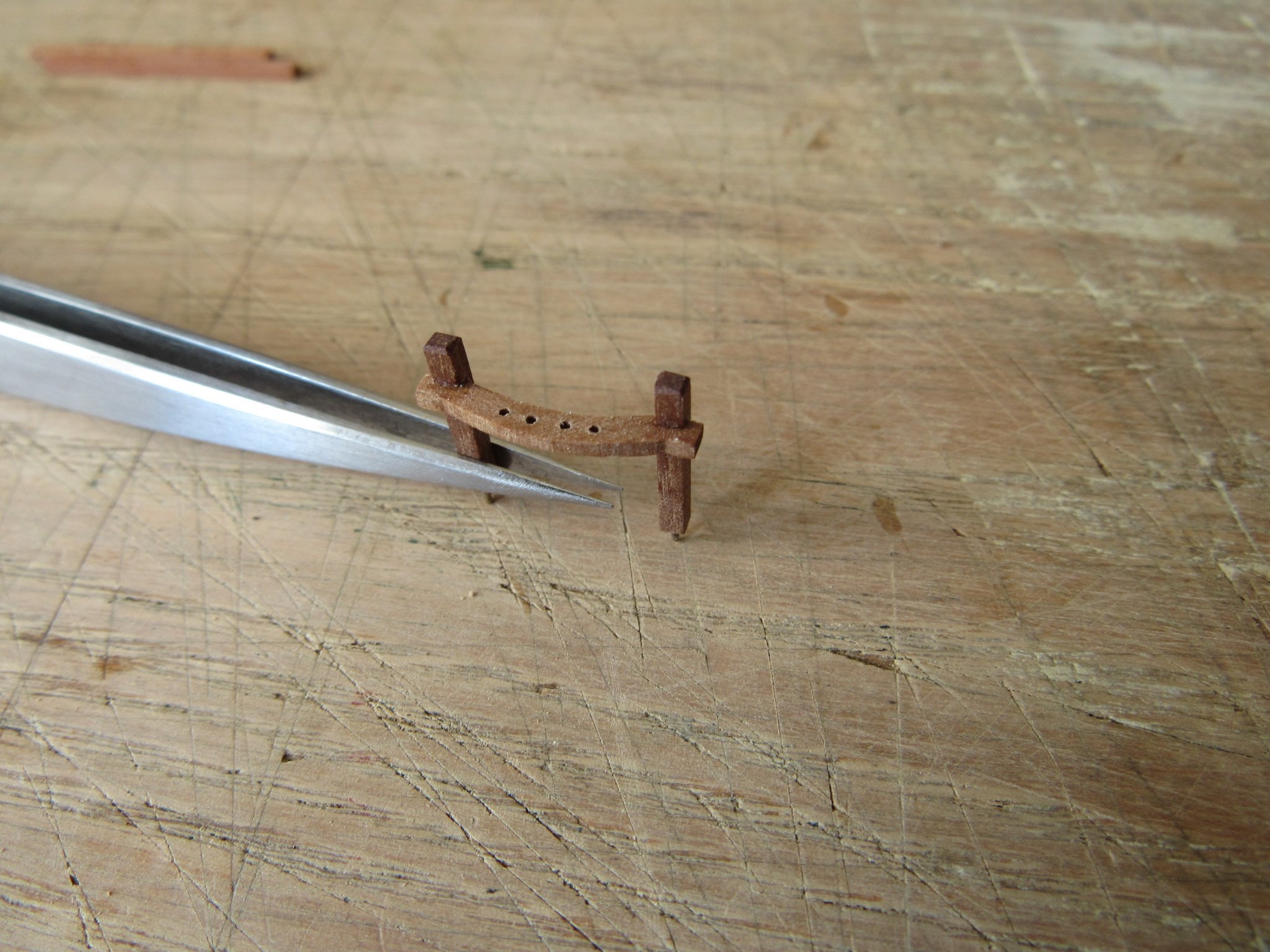
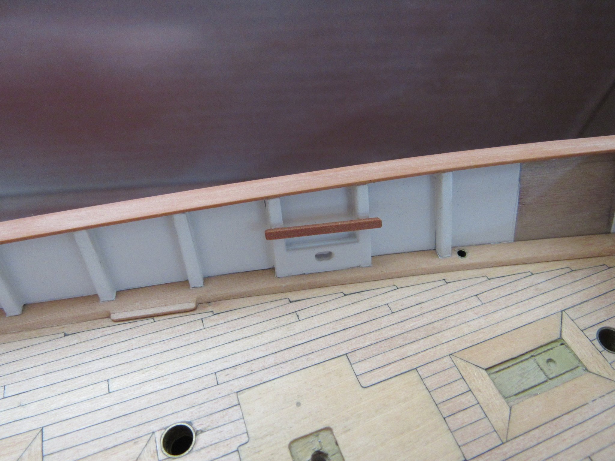
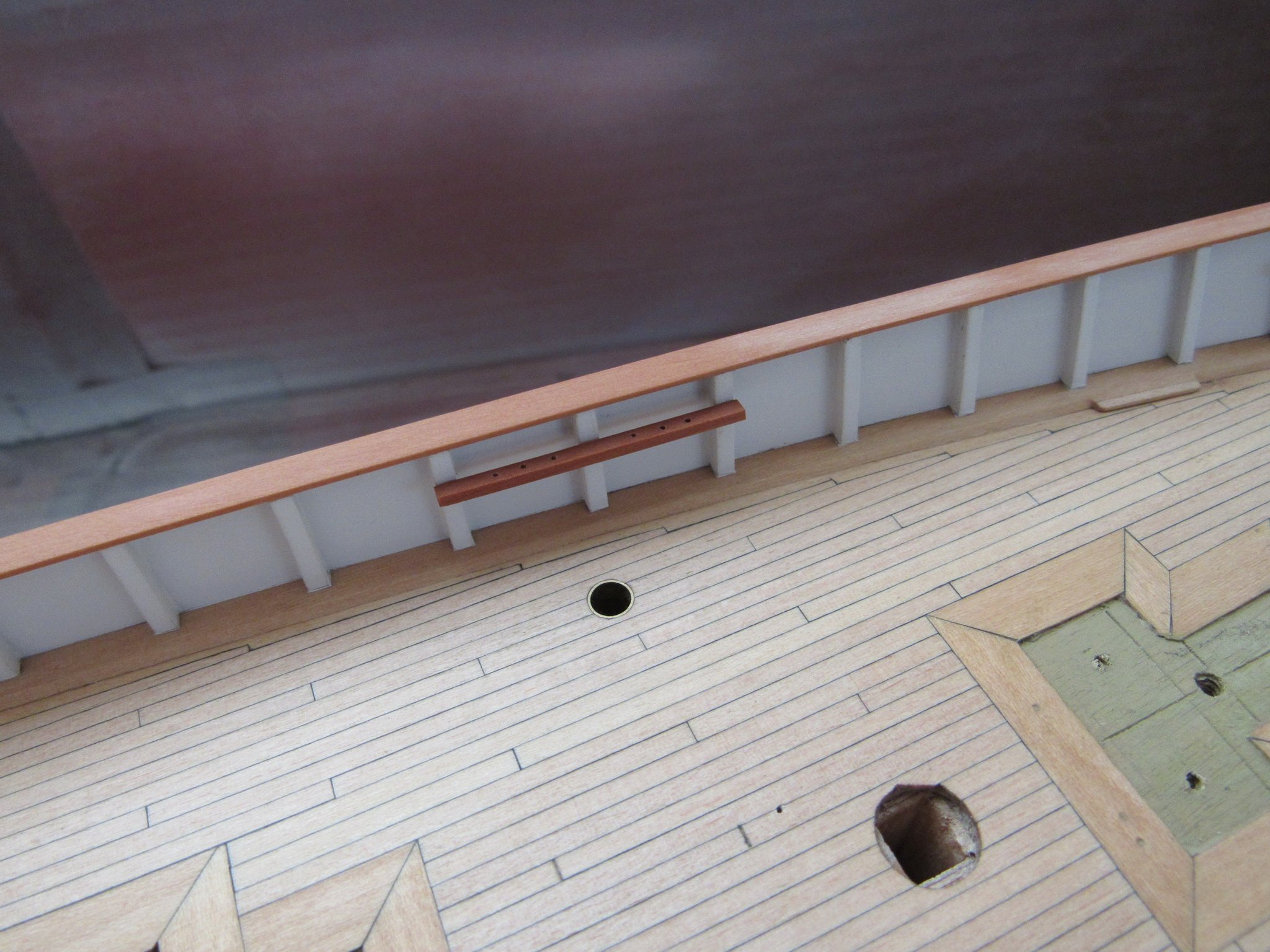
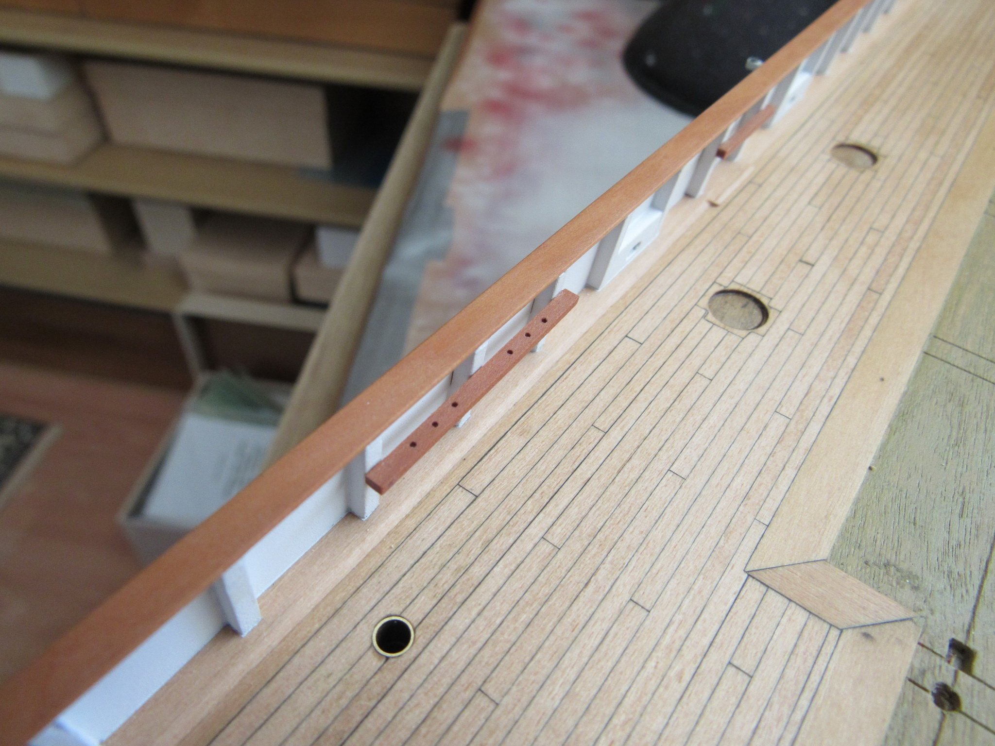
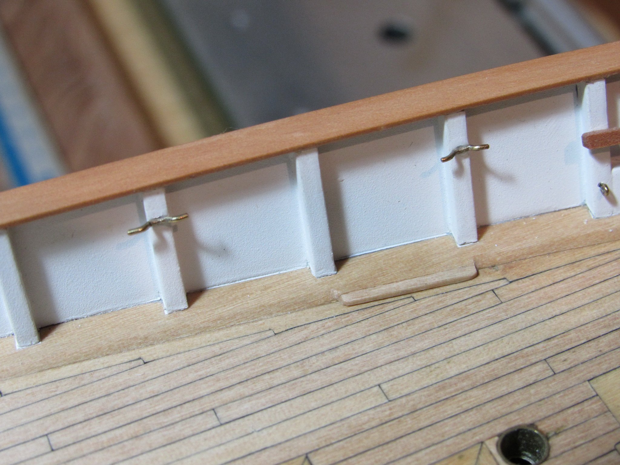
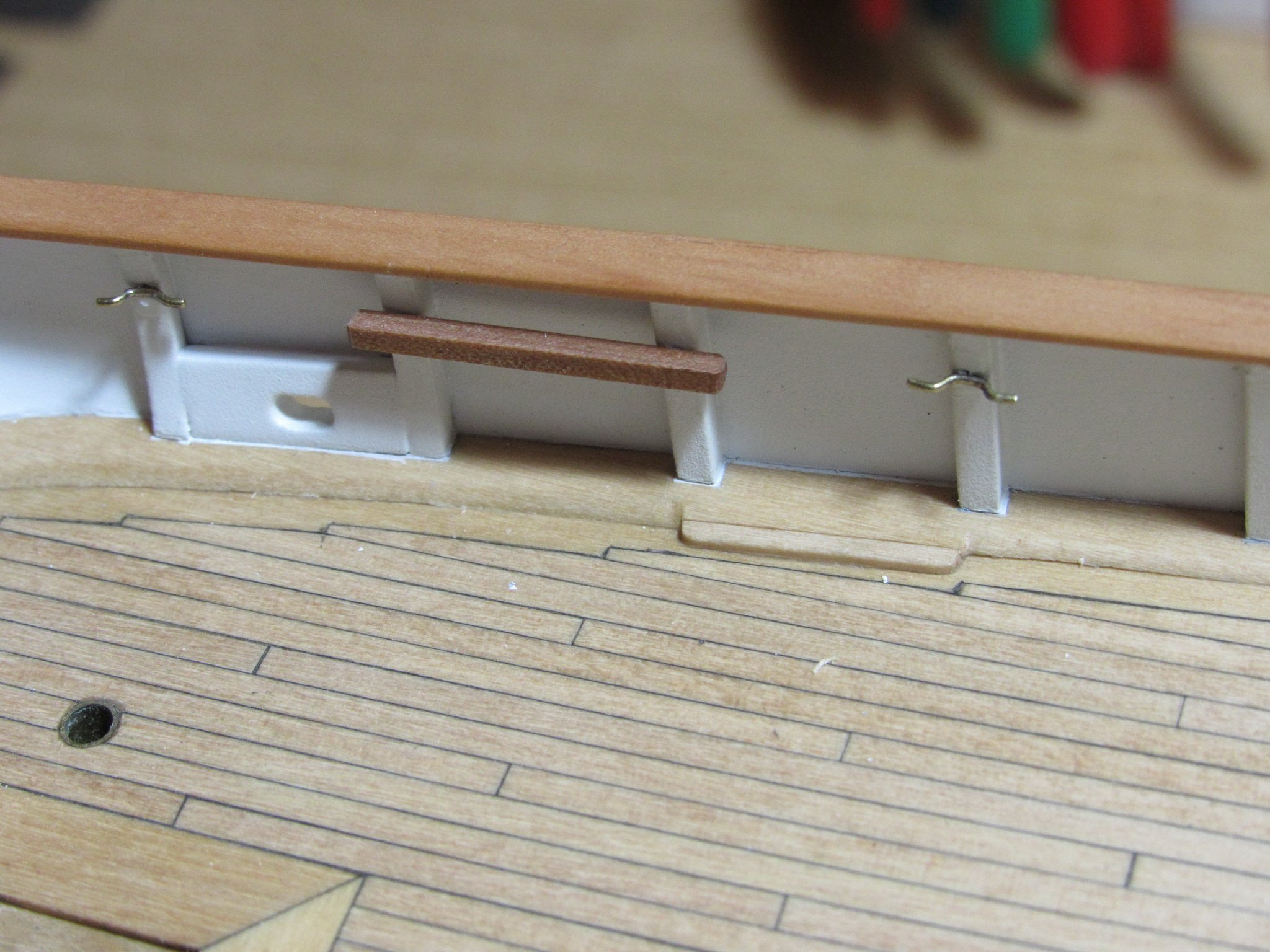
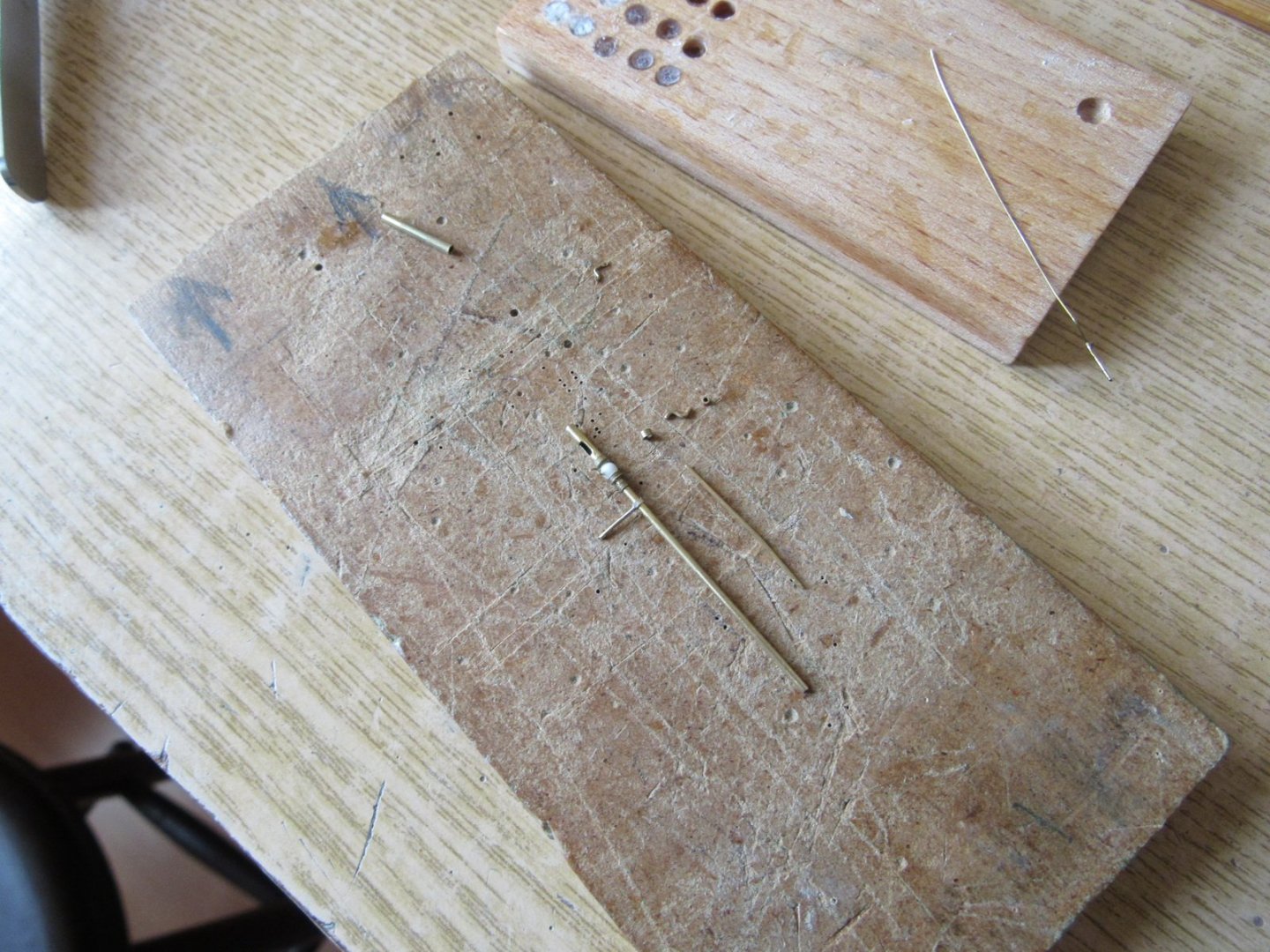
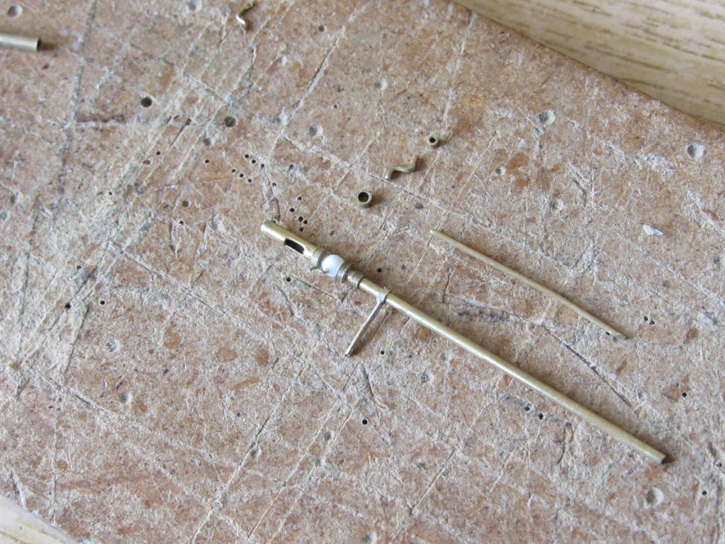
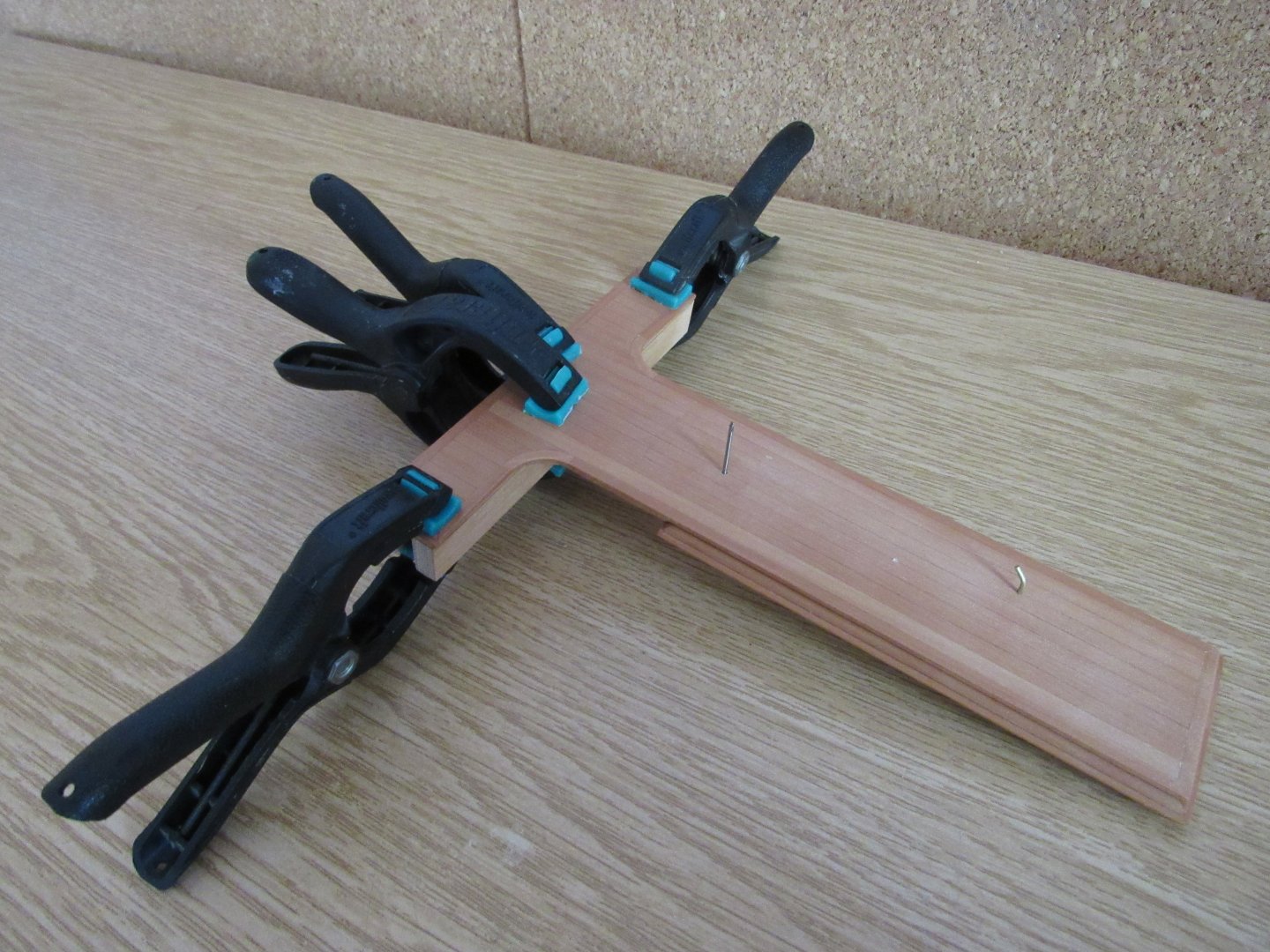
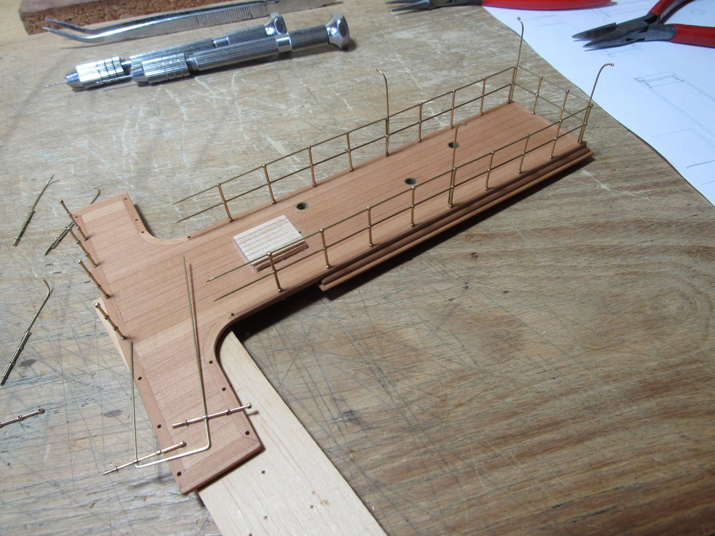
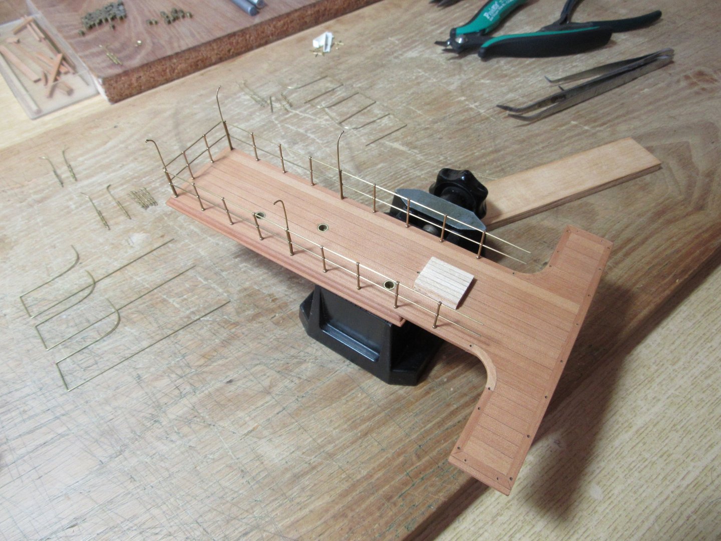
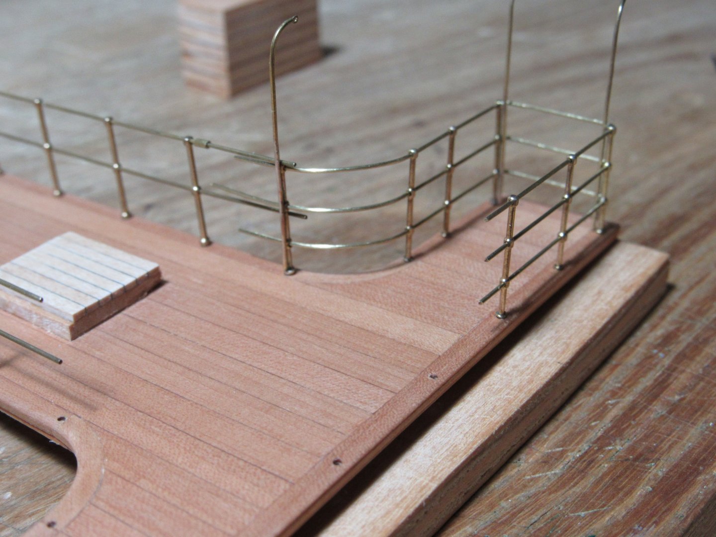
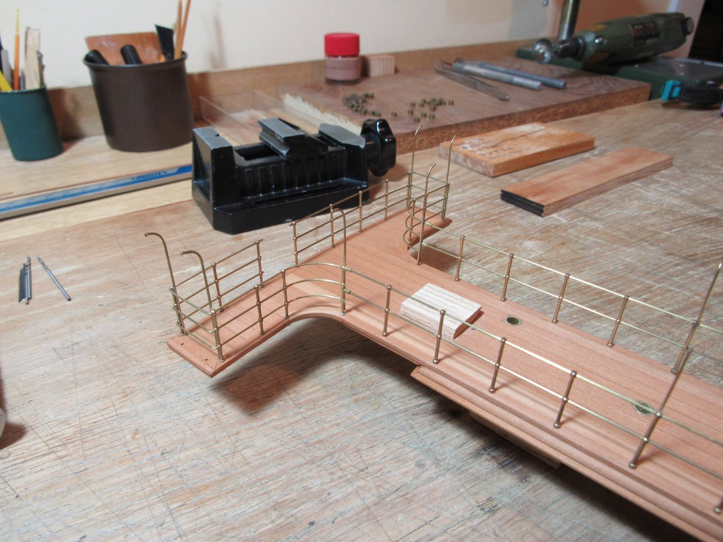
Bridge deck is made of 1 mm plywood, 0,5 mm pear strips (top) and 1 mm pear strips (underside). Adjusted the bridge supports and installed brass tubes as bushings in the deck and in the handrail Some part of the stanchions have 2 rails and some part of them have 3 rails. I modified the stanchions because the 2 rails and 3 rails did not have the same height. 3 rail stanchions were higher. I sanded down the bulges at the bottom flash and made a new one. I also sanded down the bulges for the rails as they are too bold.


- 272 replies
-
- 16
-
-
-
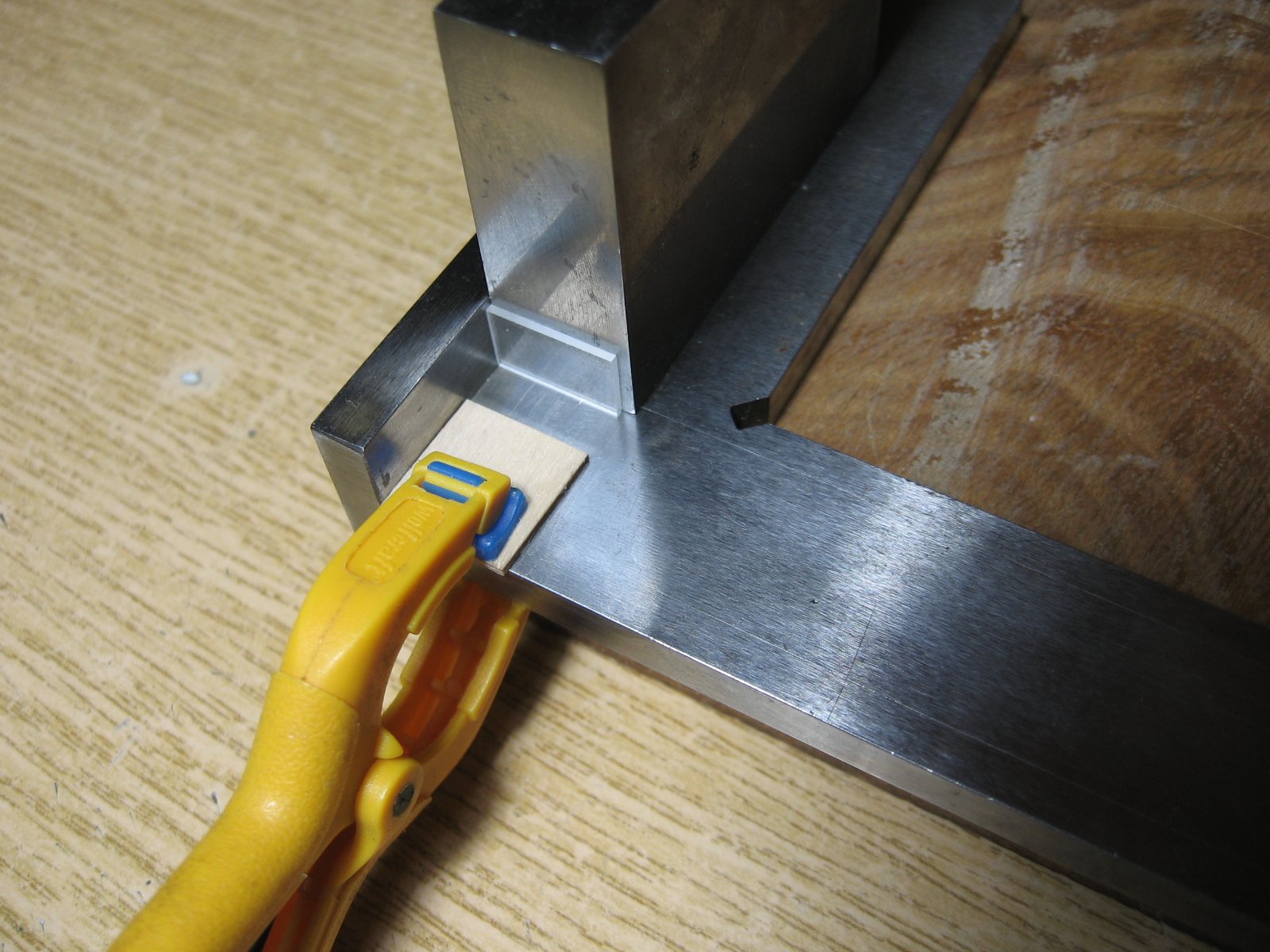
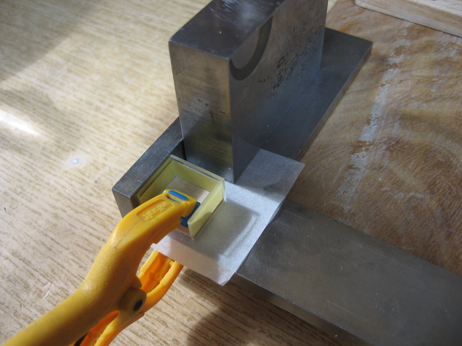
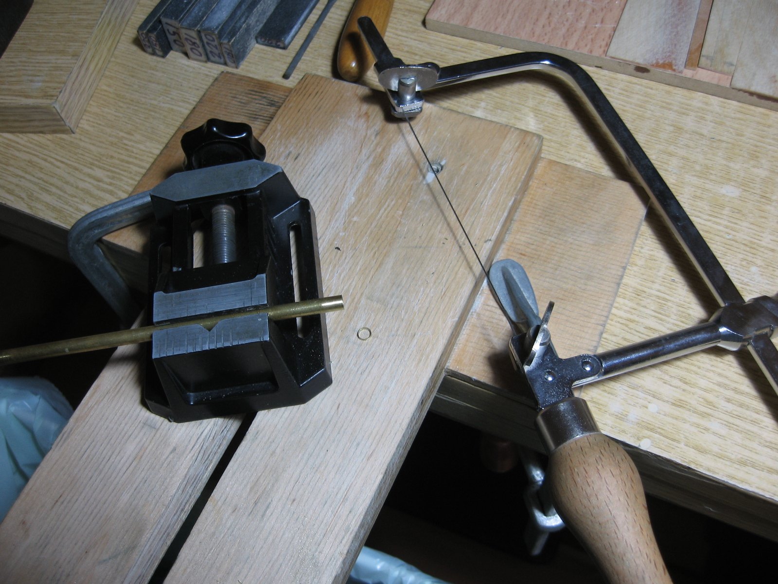
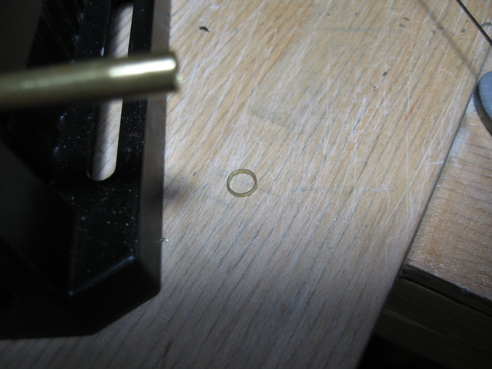
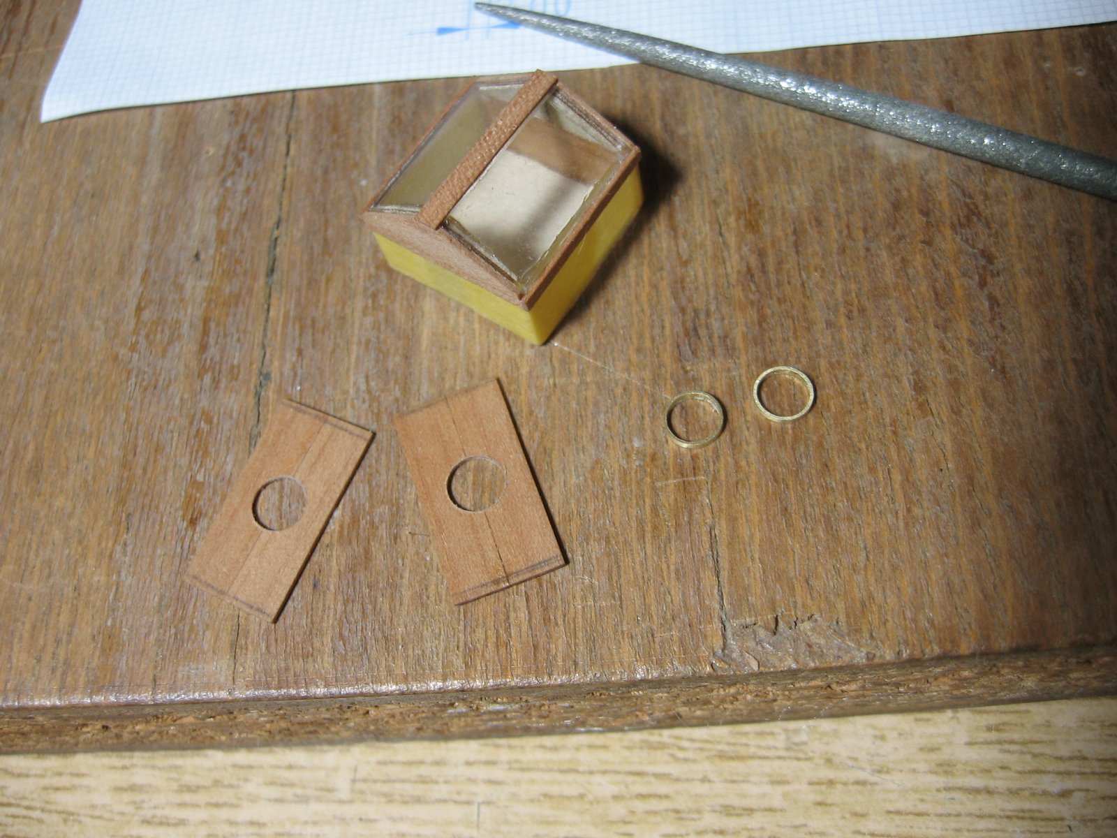
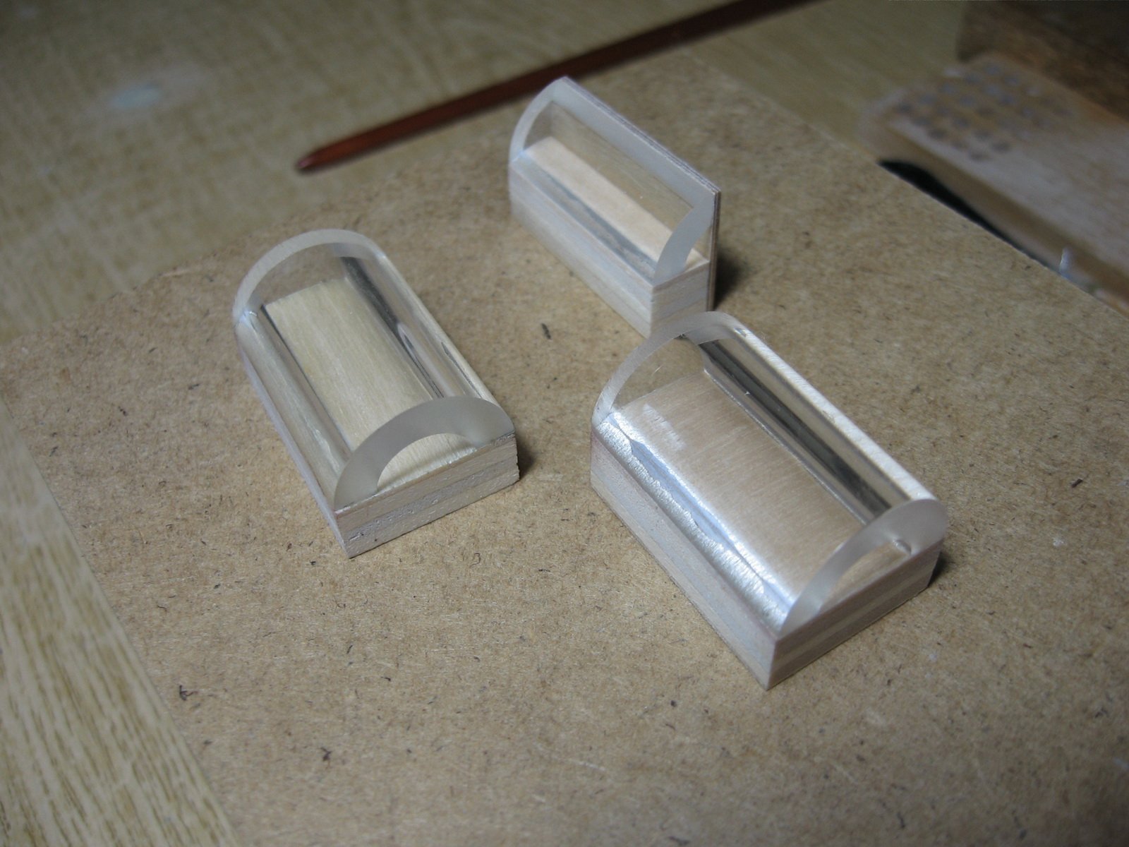
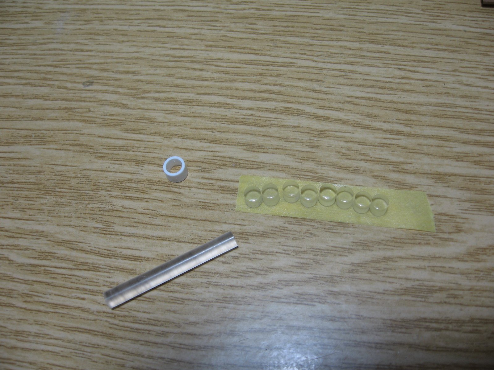
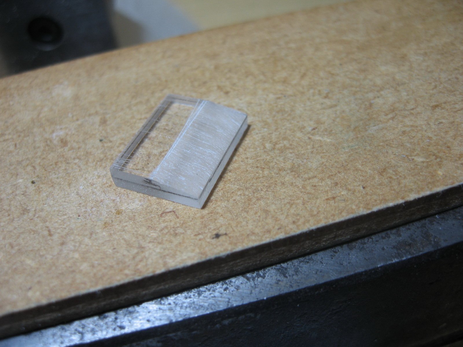
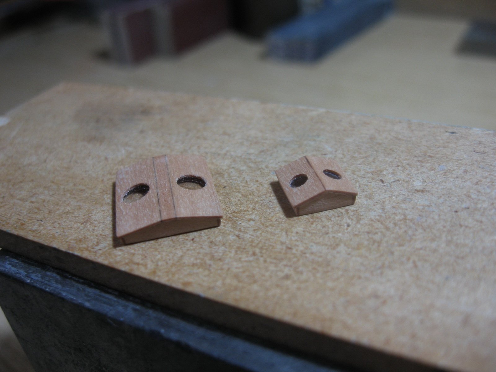
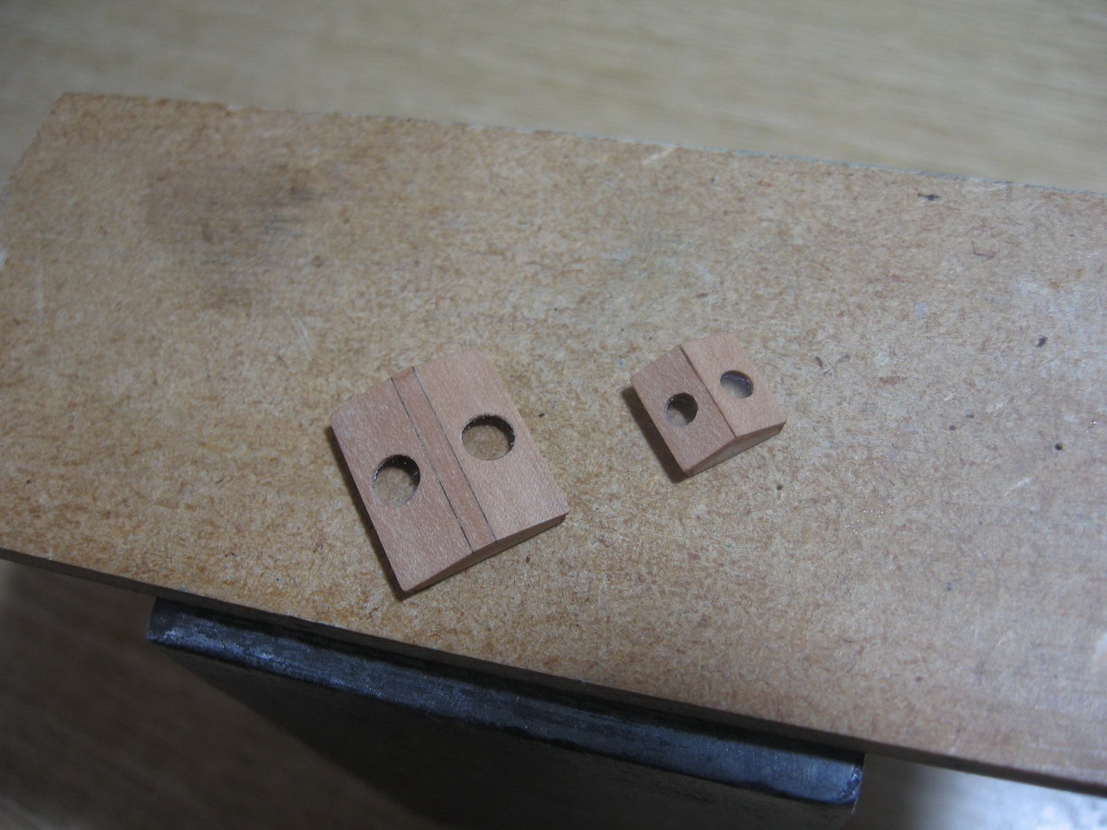
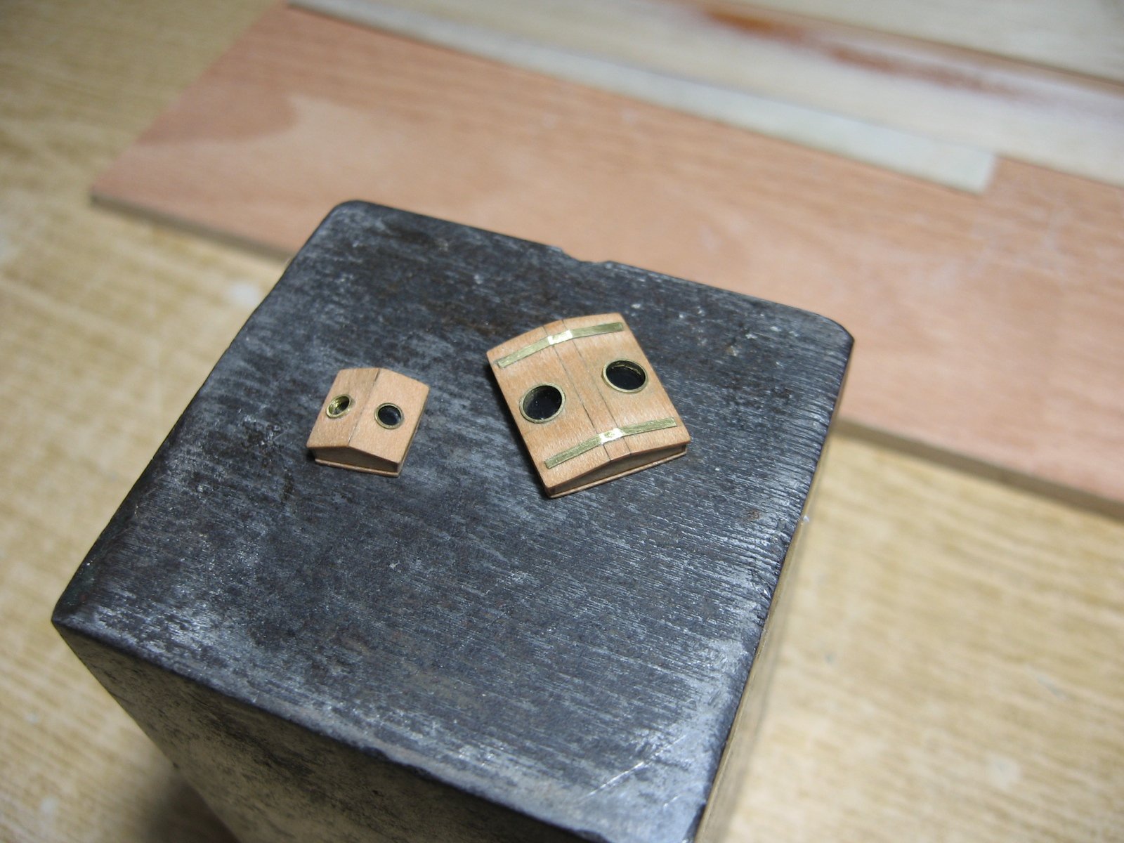
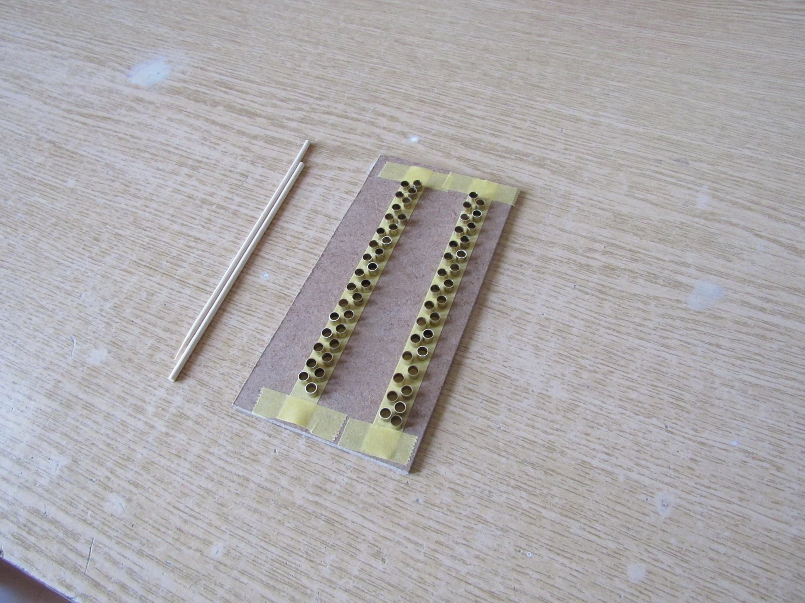
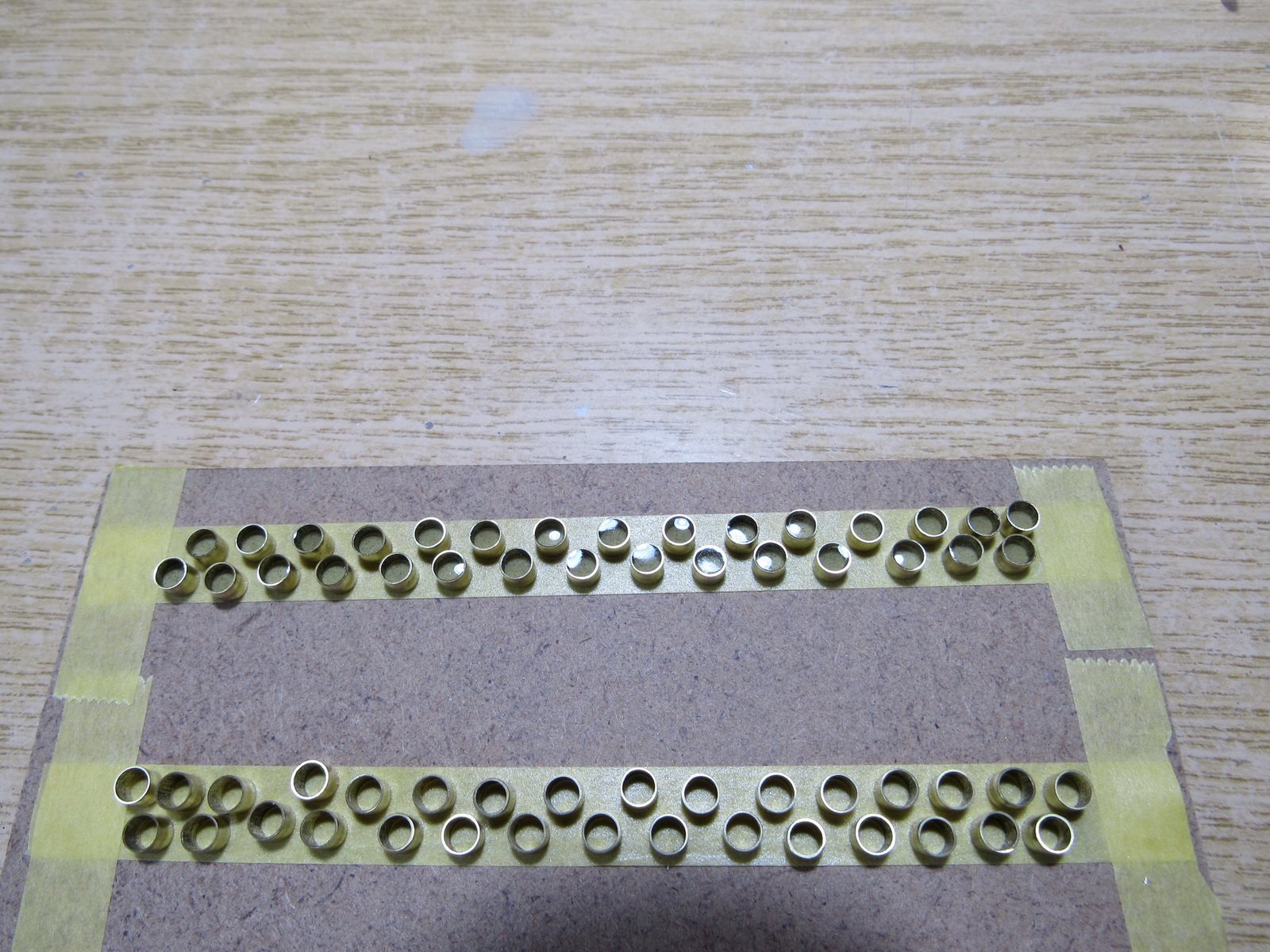
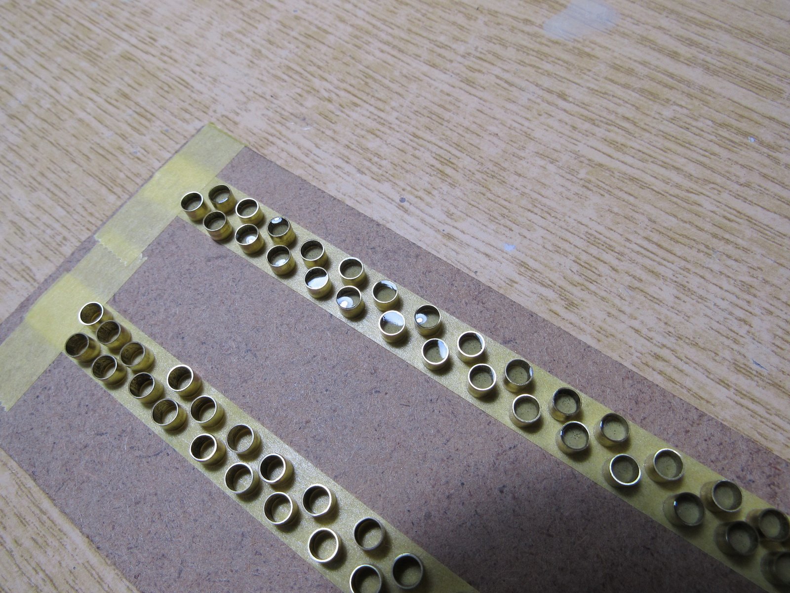
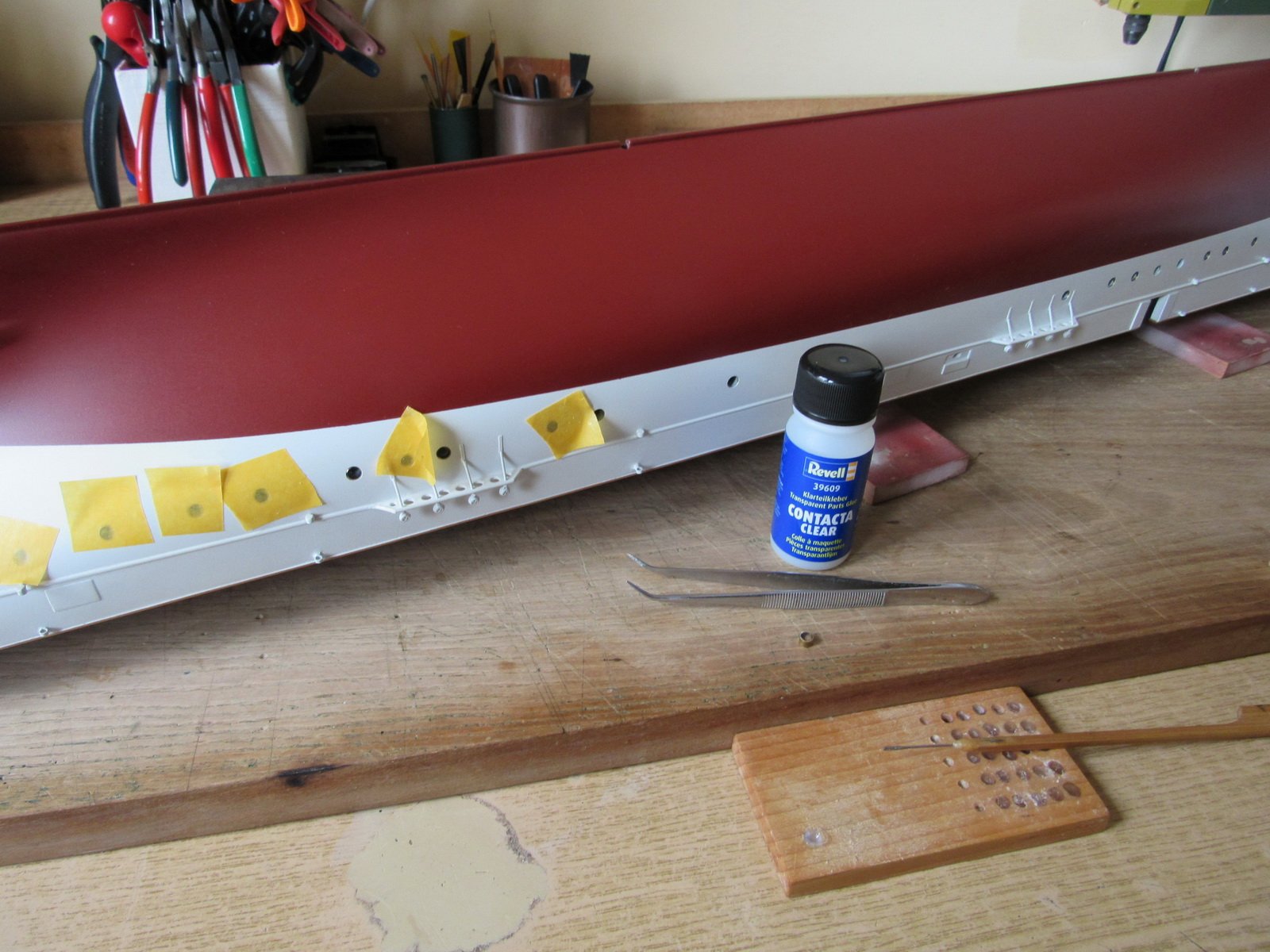
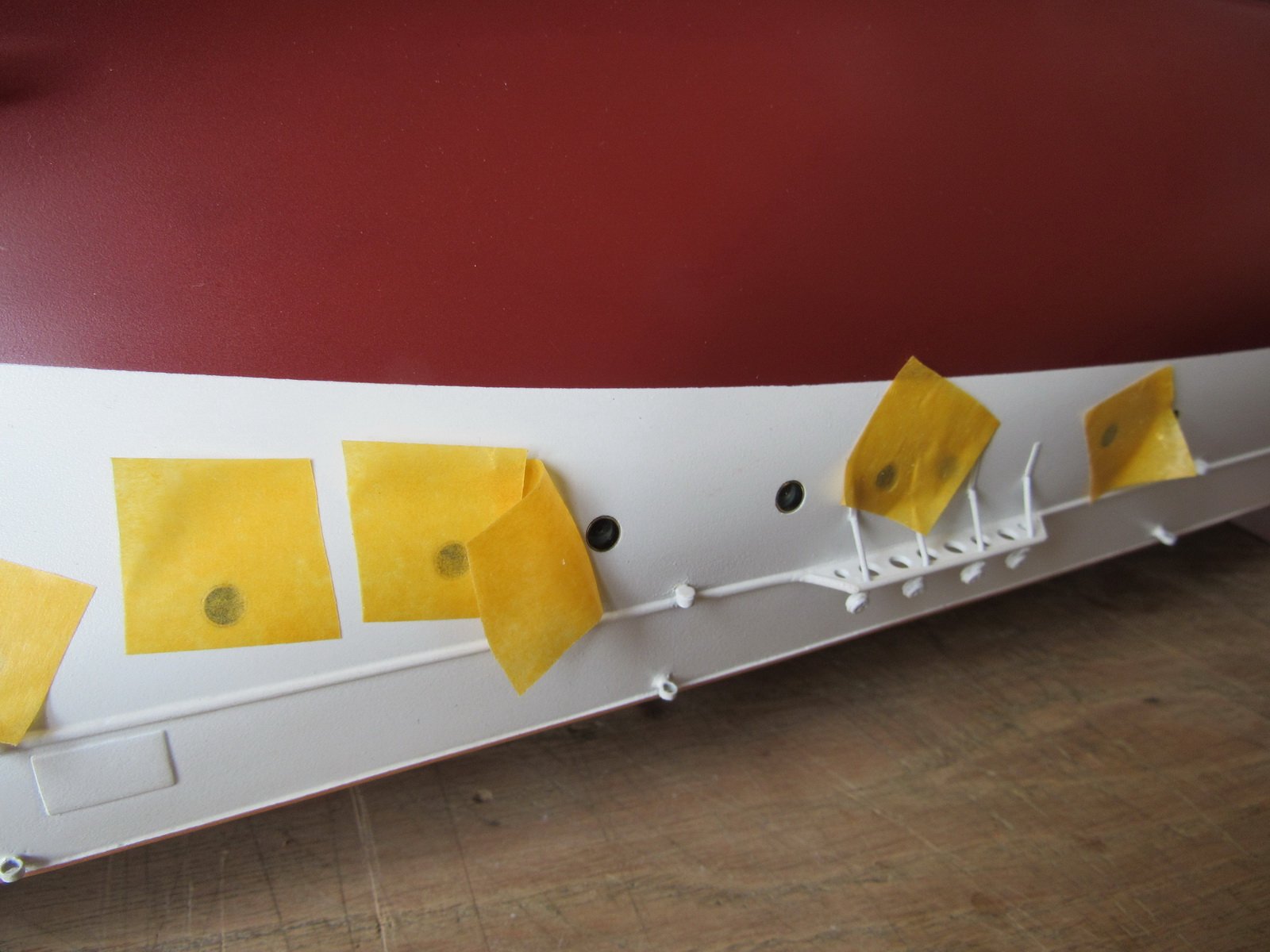
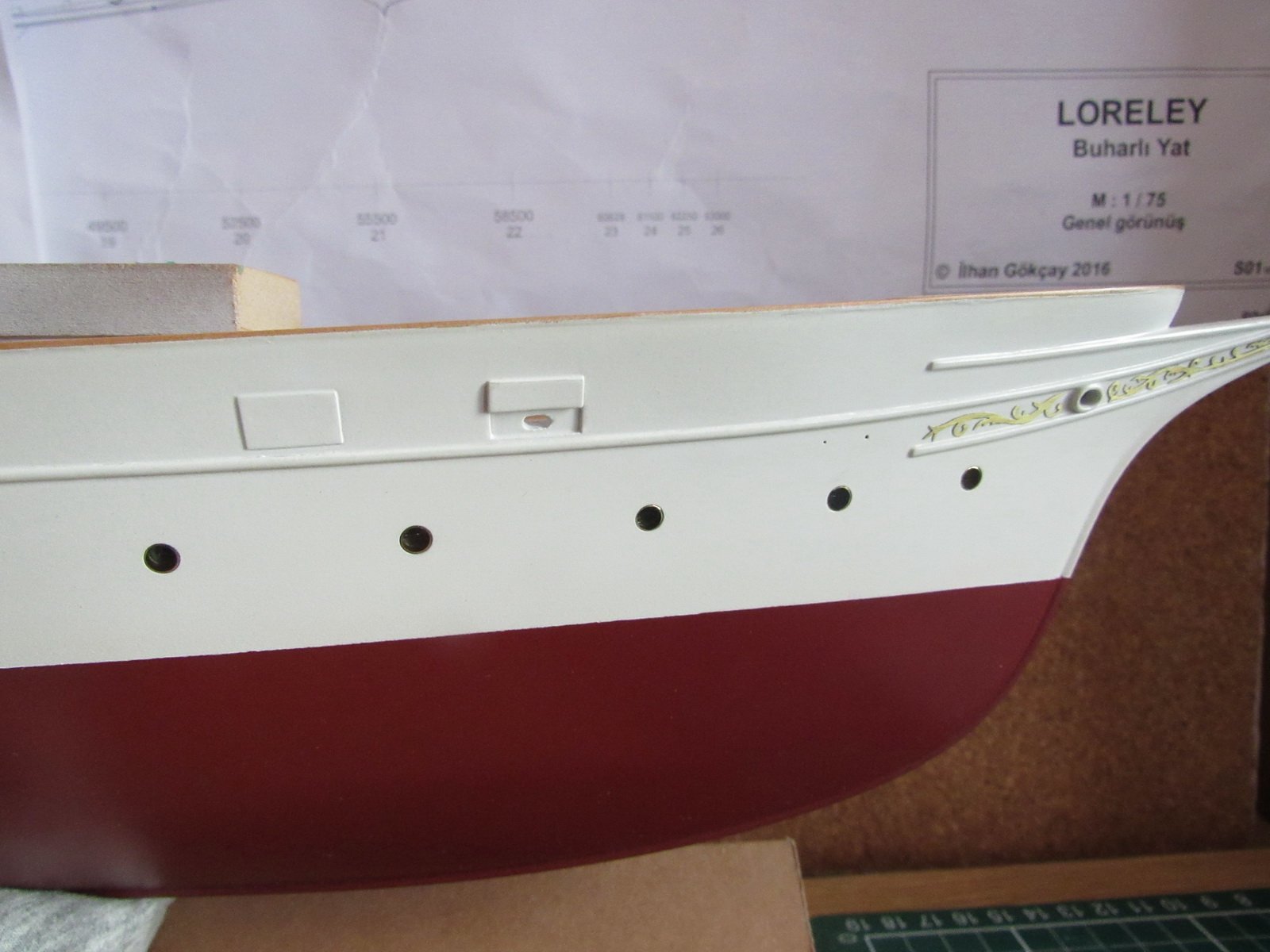
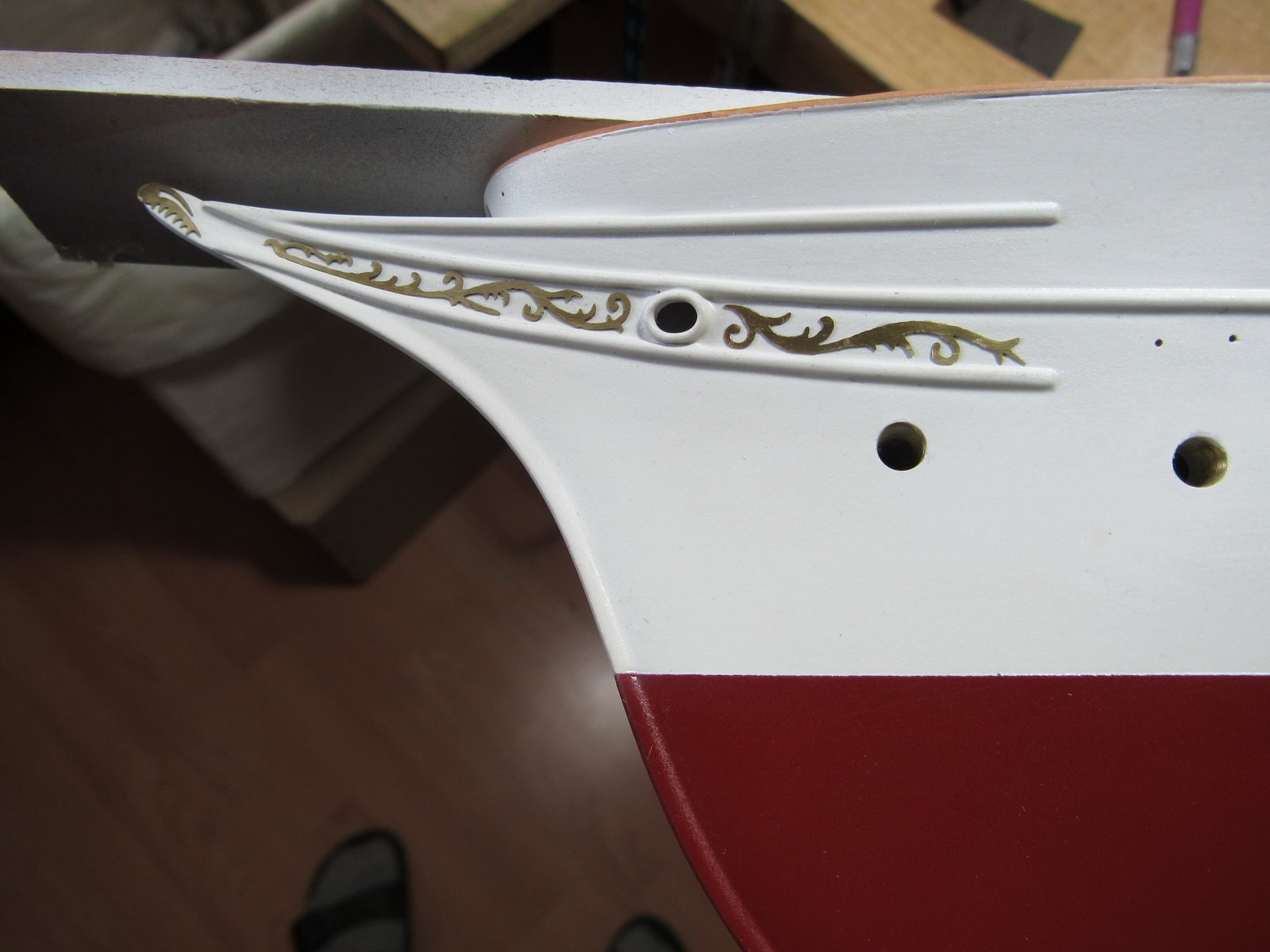
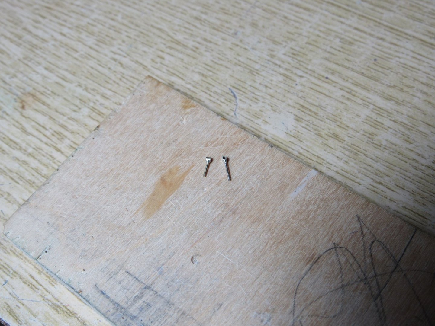
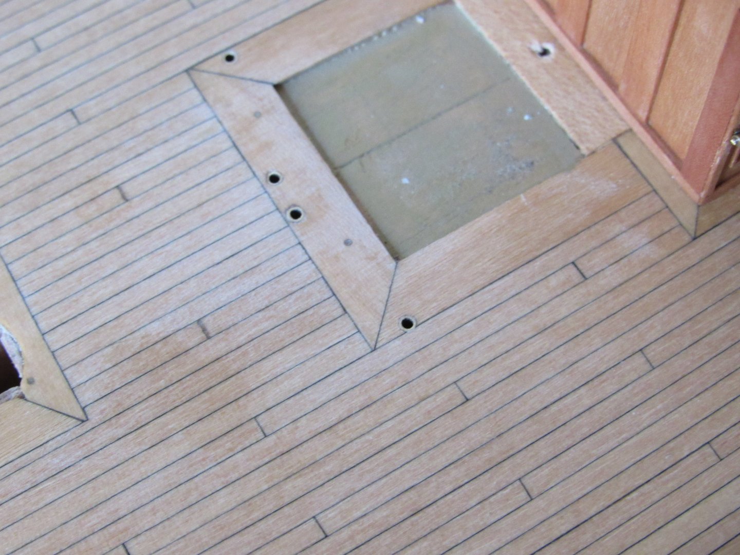
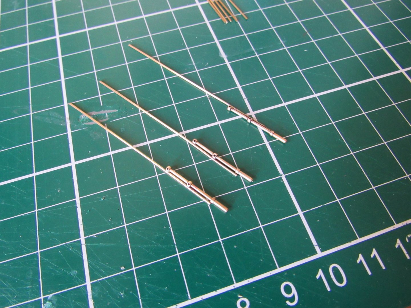
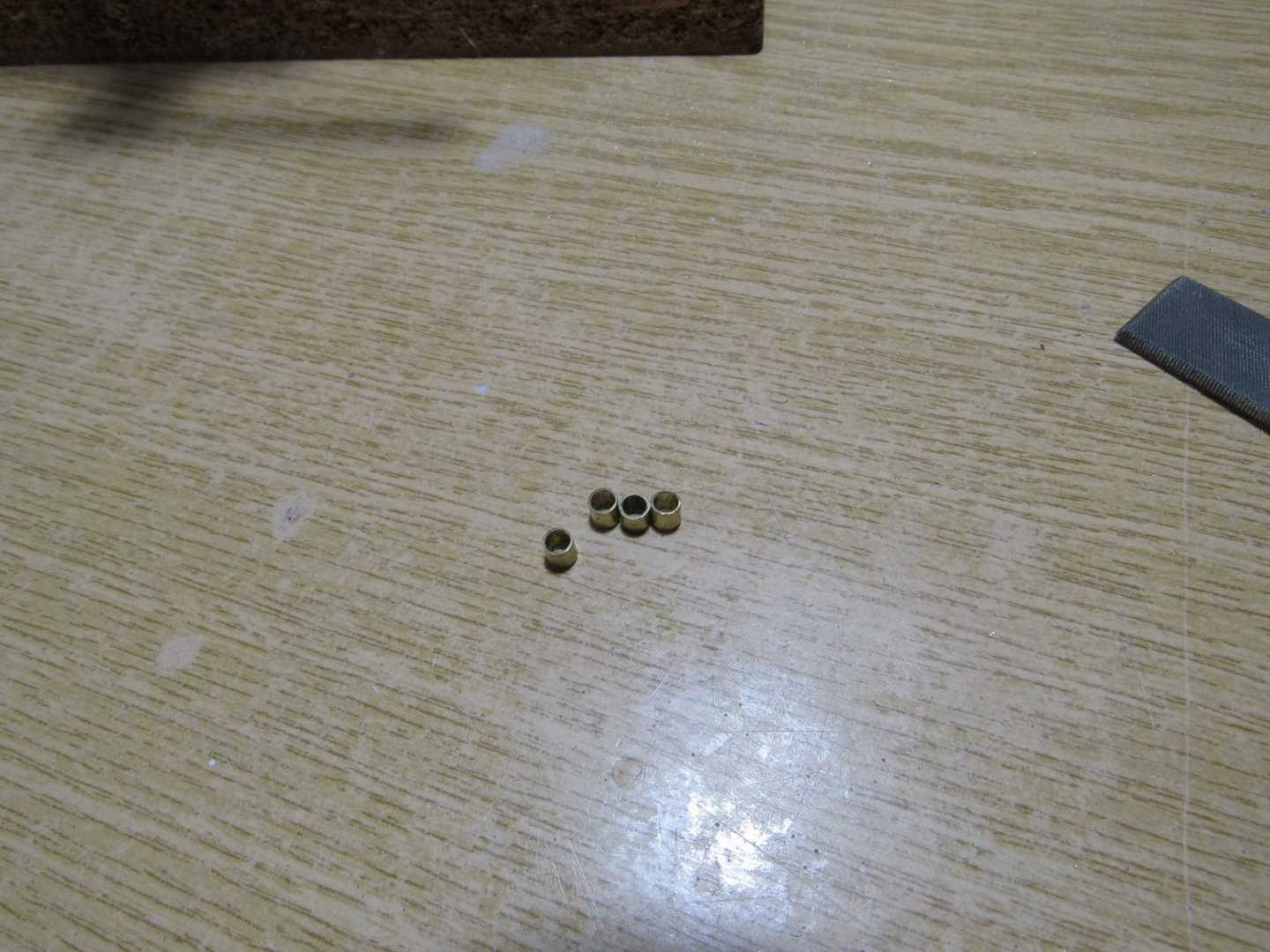
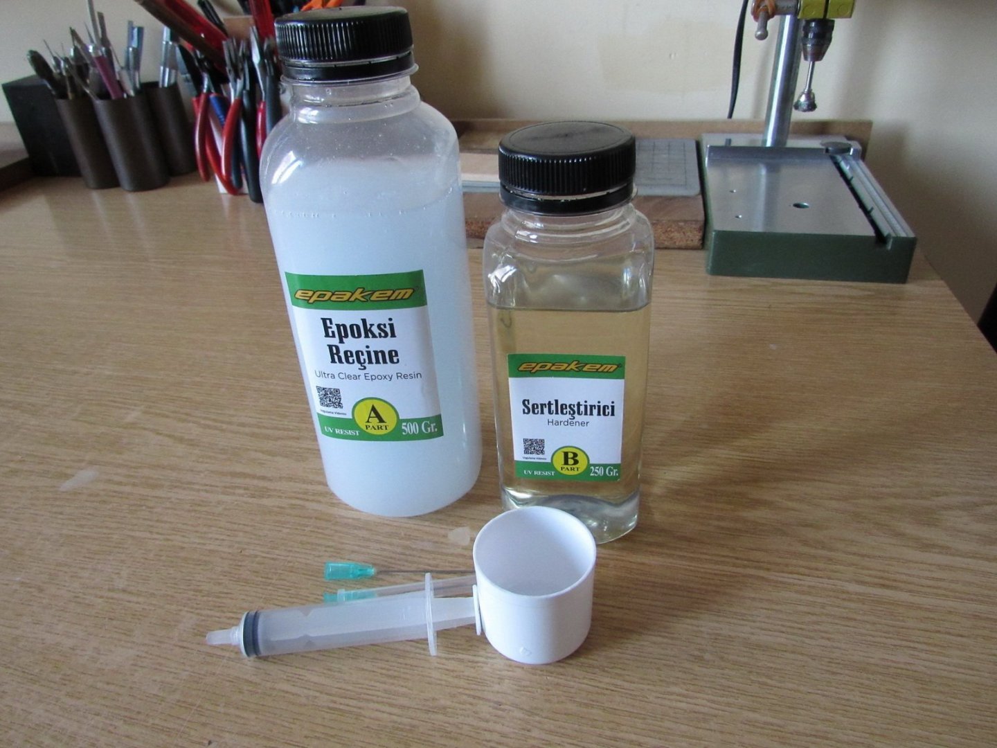
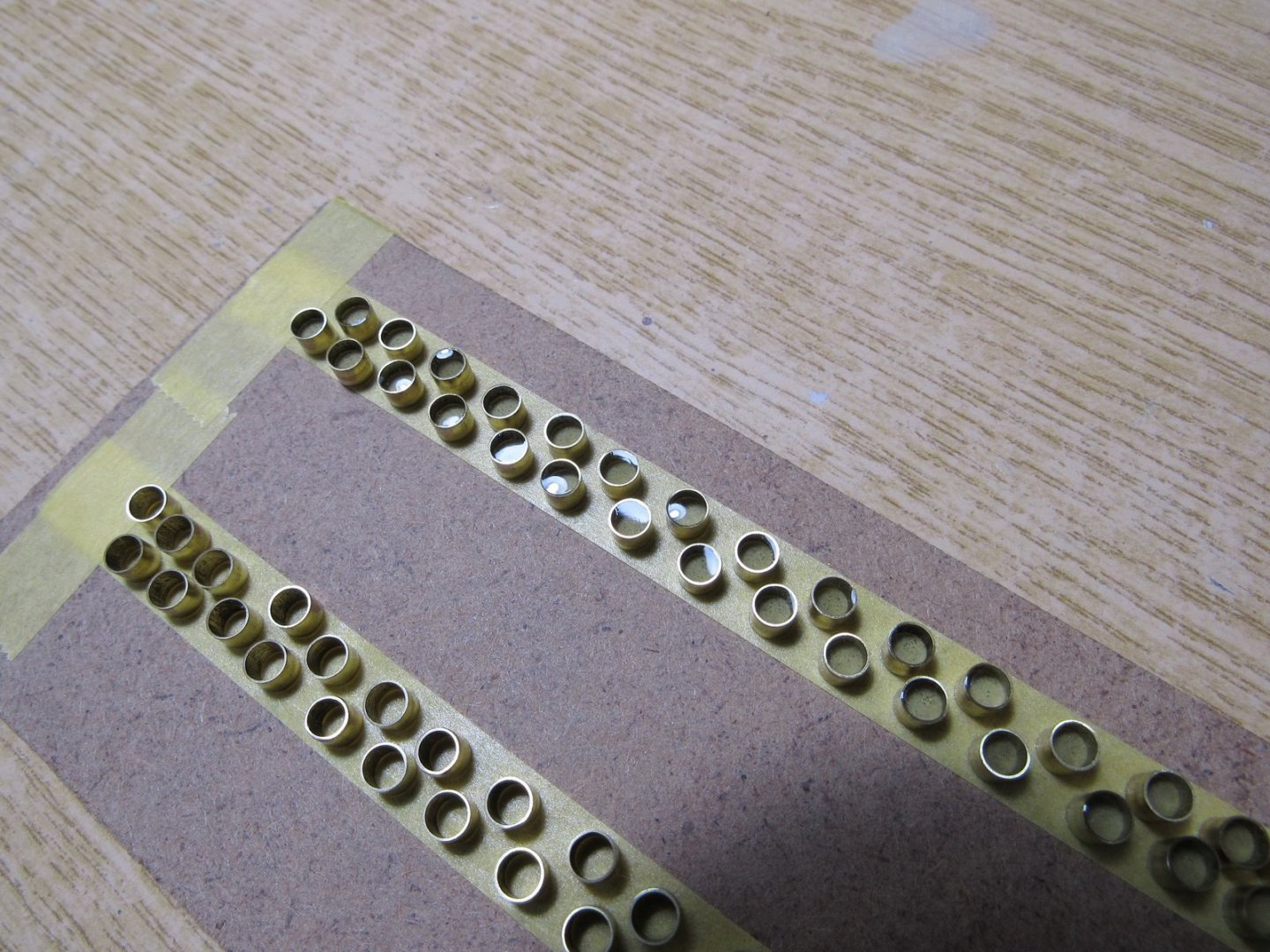
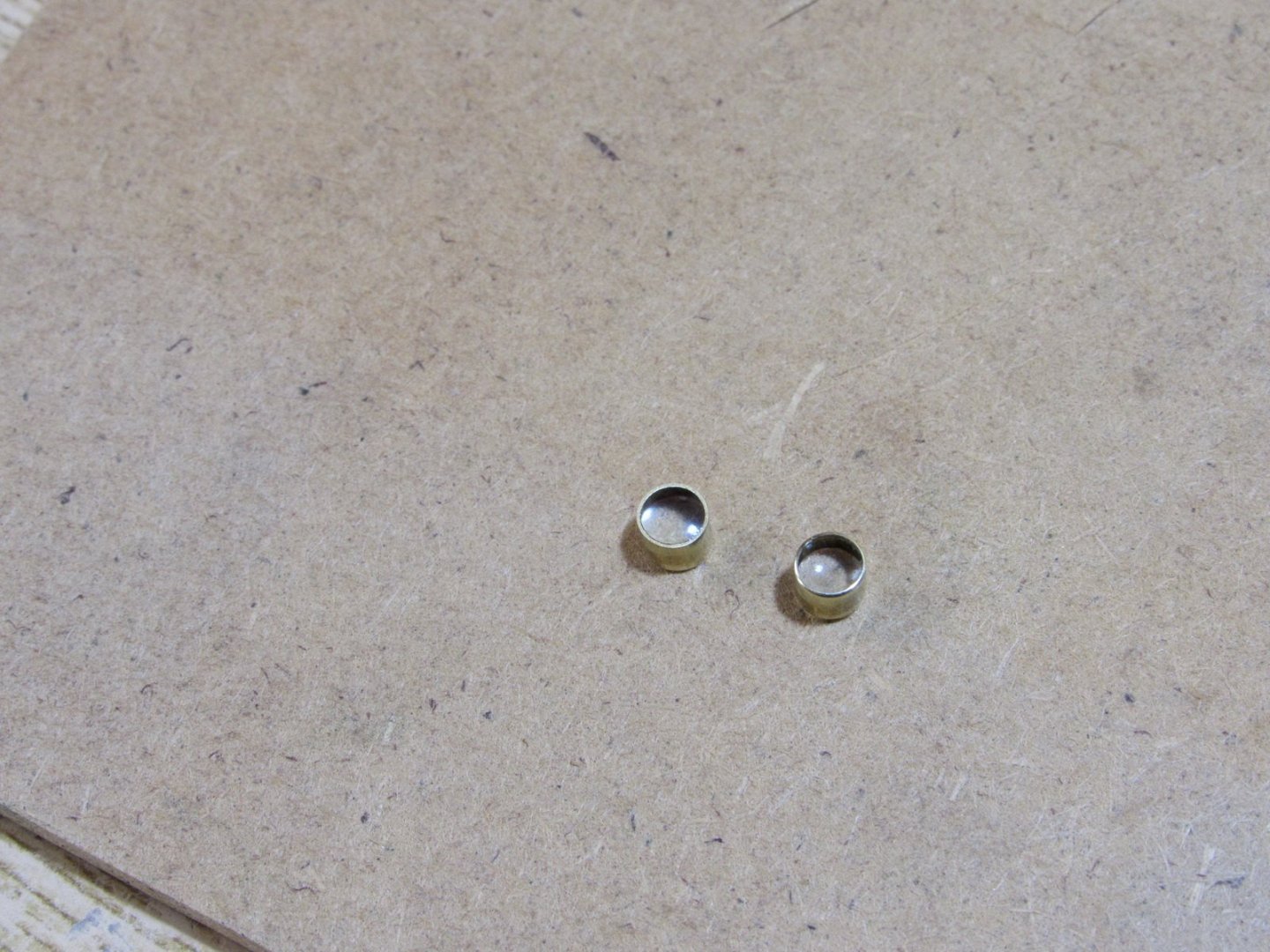
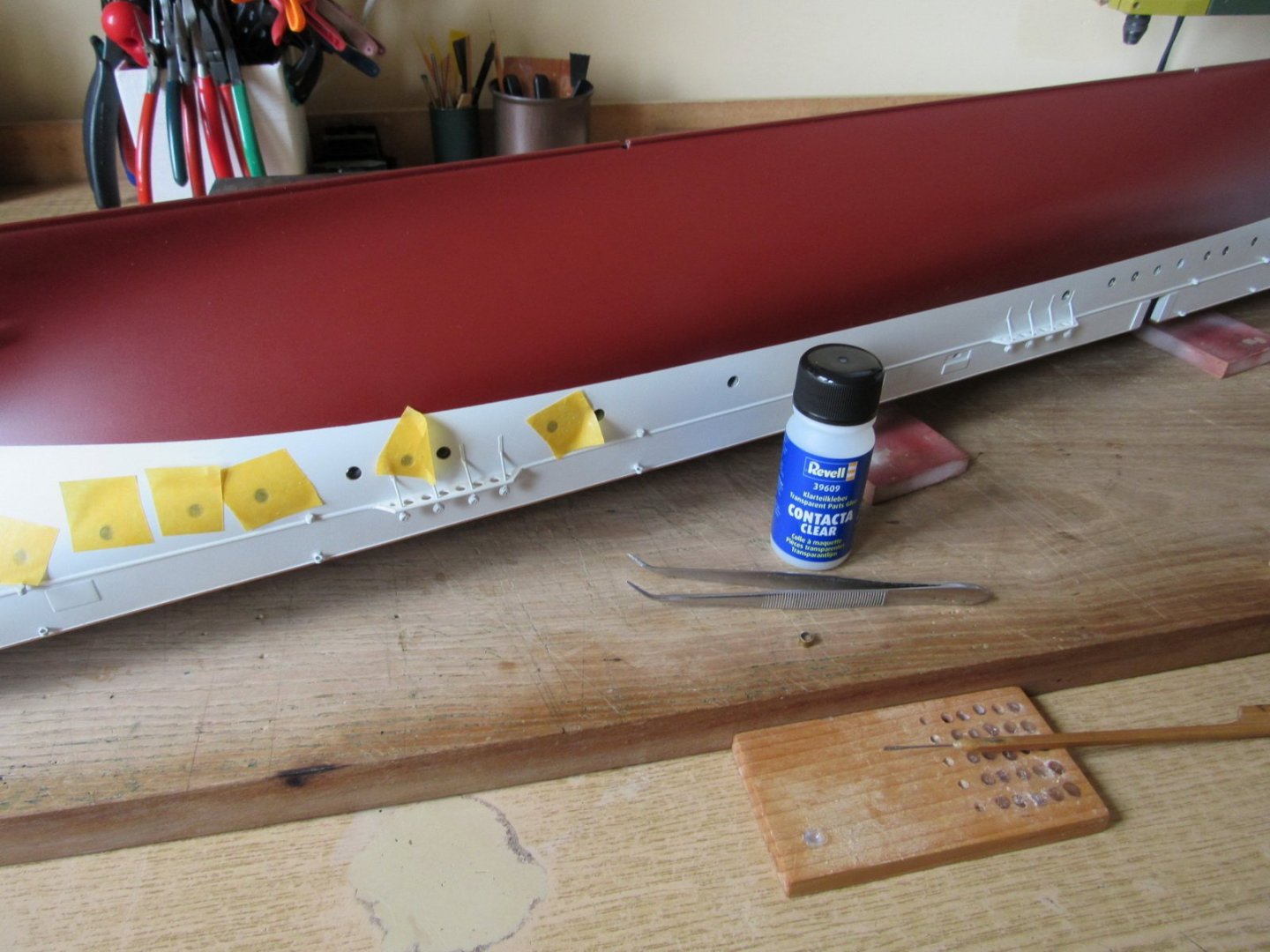
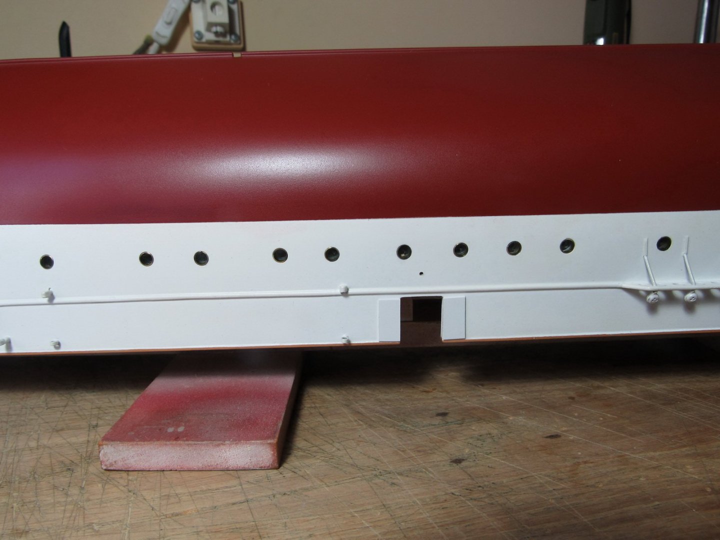
I made the portholes of brass tubes which fits exactly to the tubes at the hull. I filled them with epoxy and glued with Revel Contacta Clear.


-
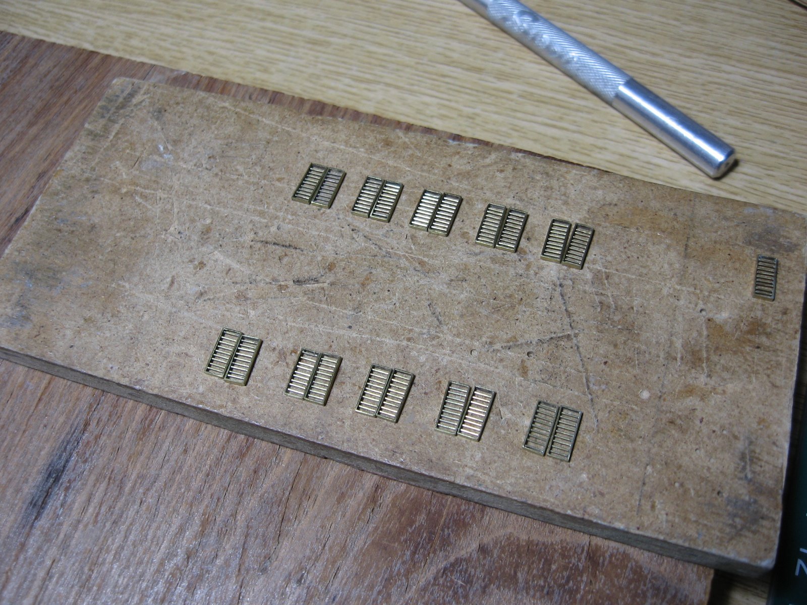
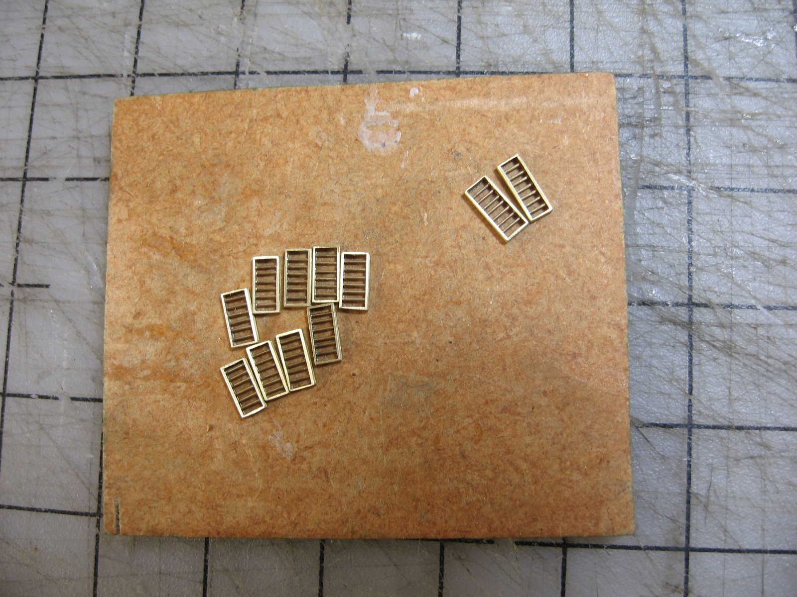
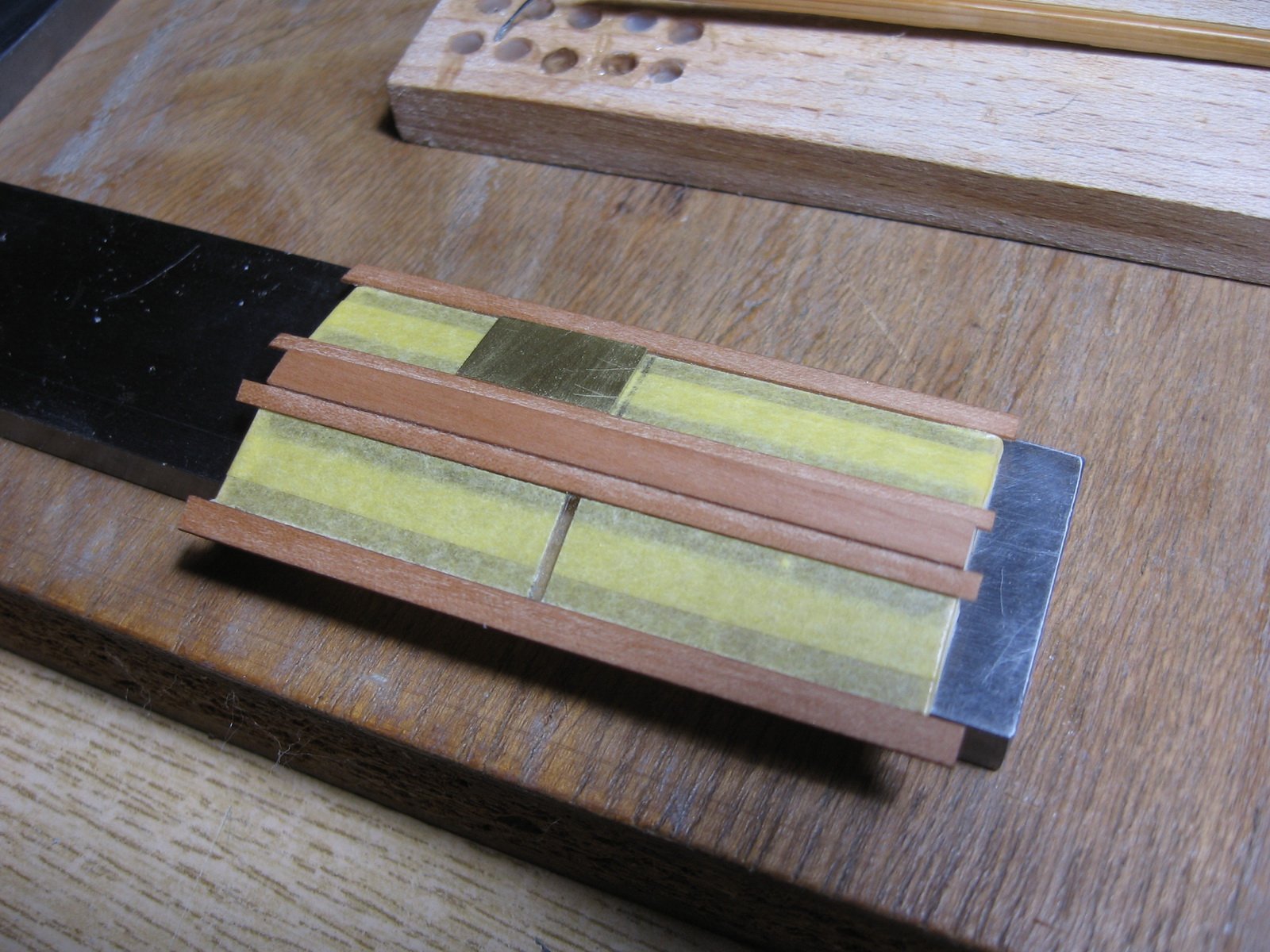
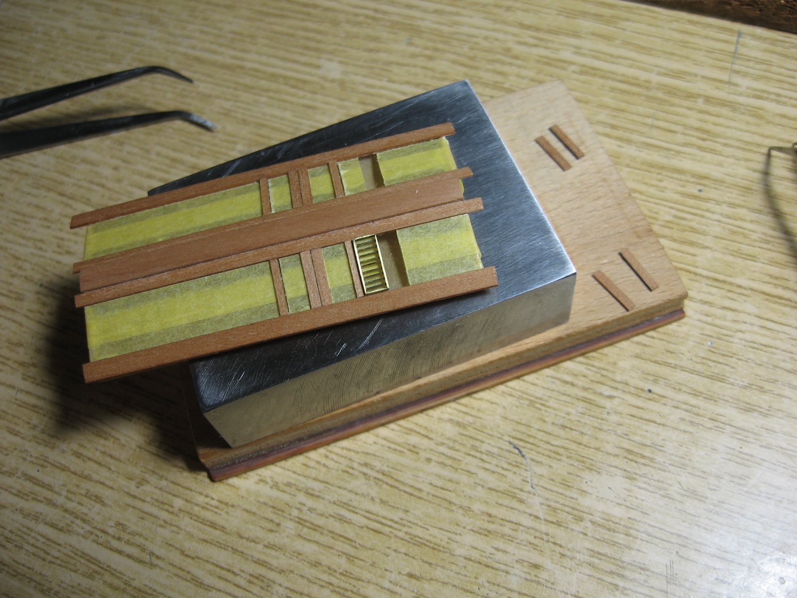
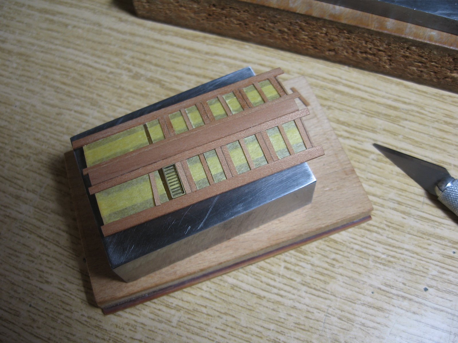
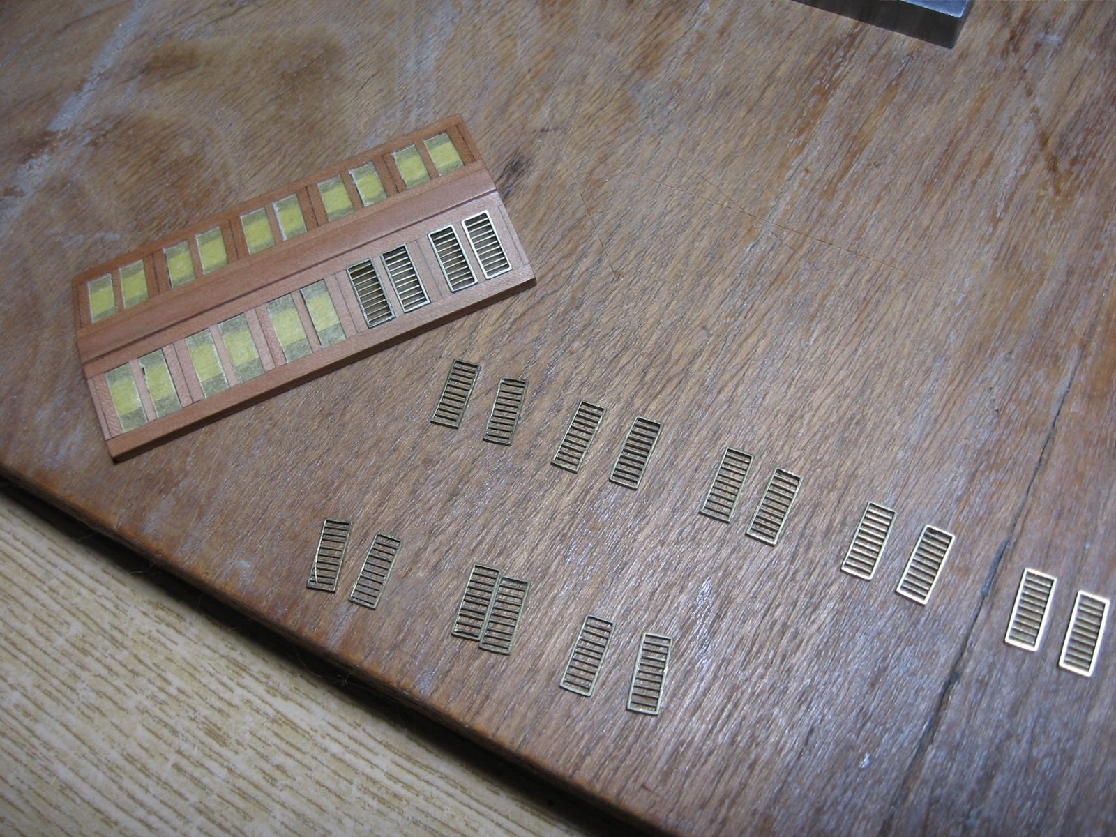
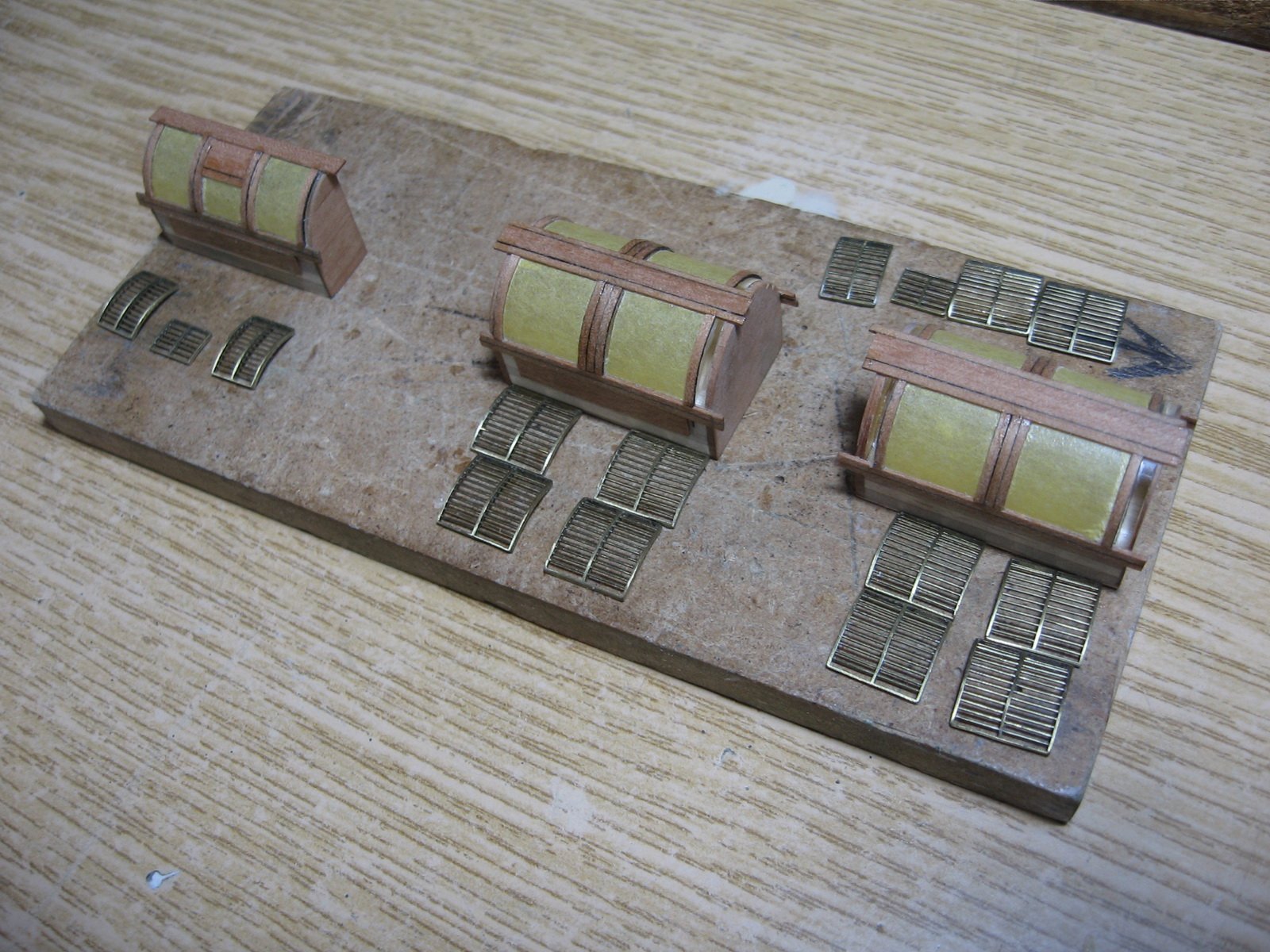
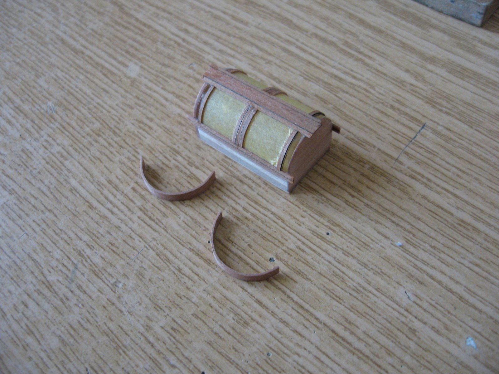
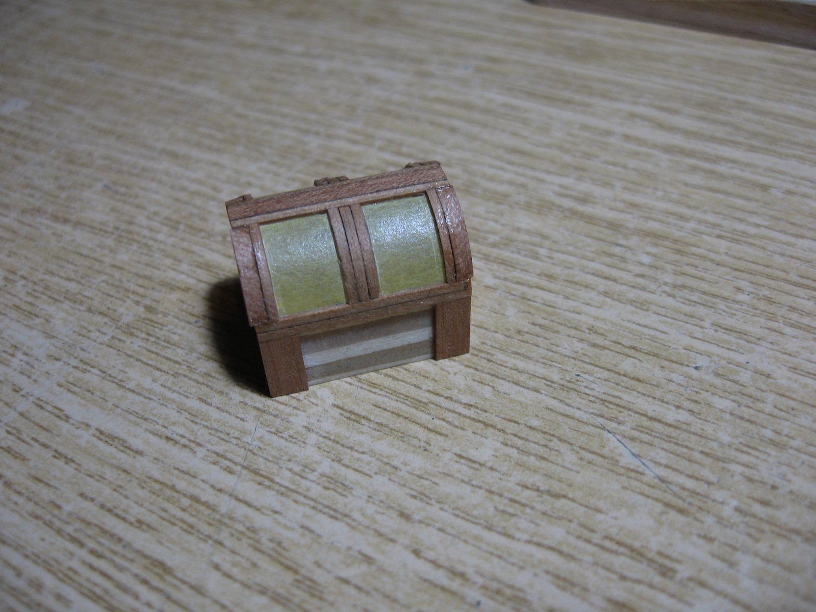
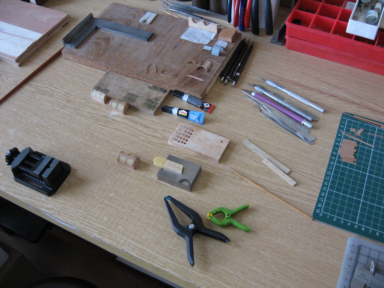
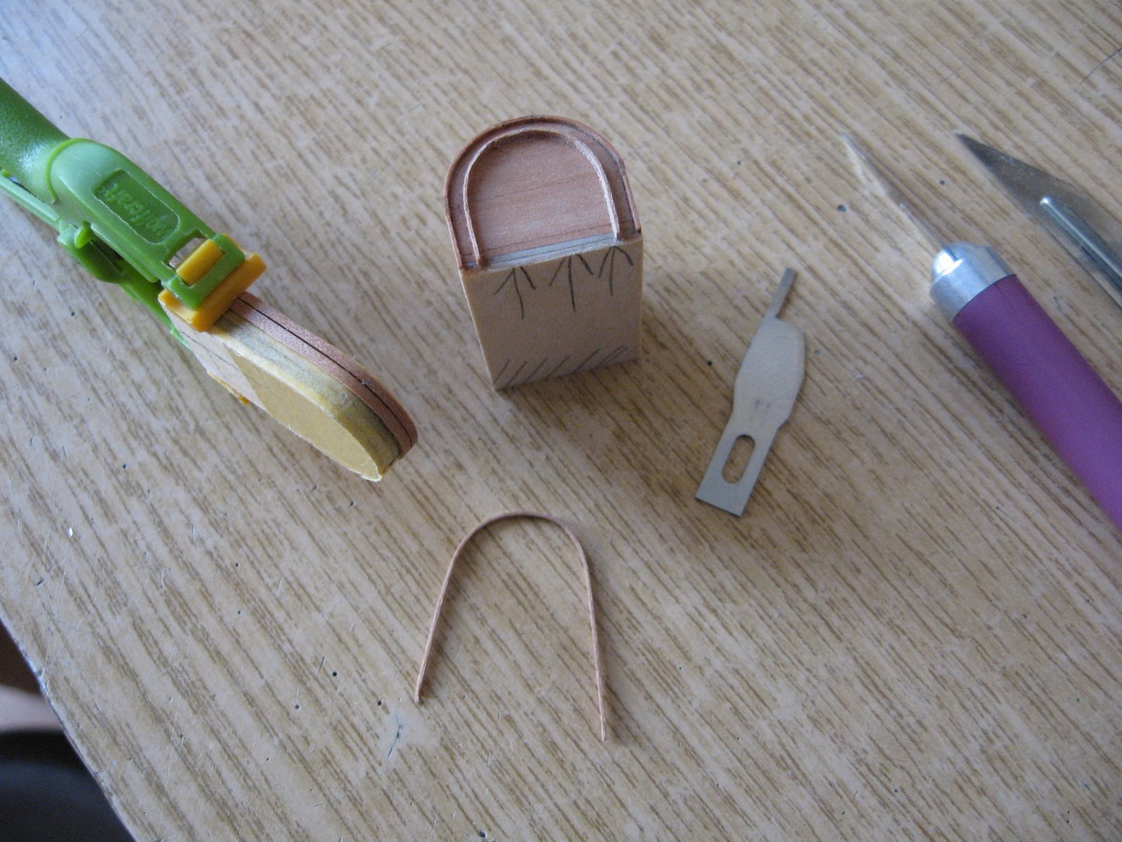
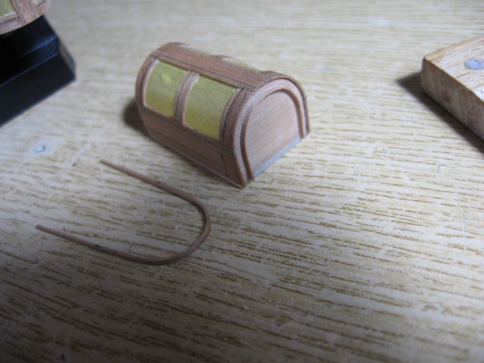
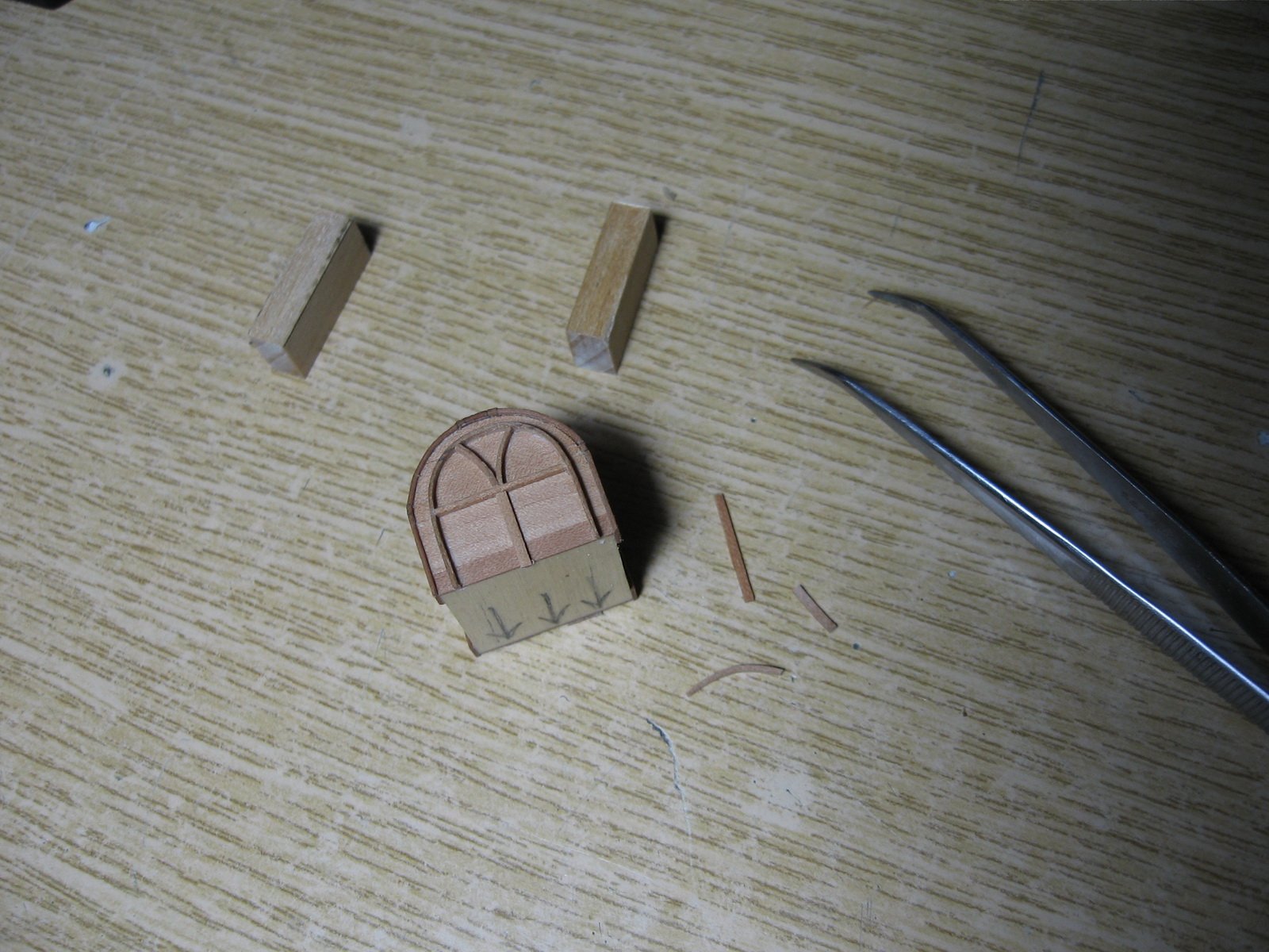
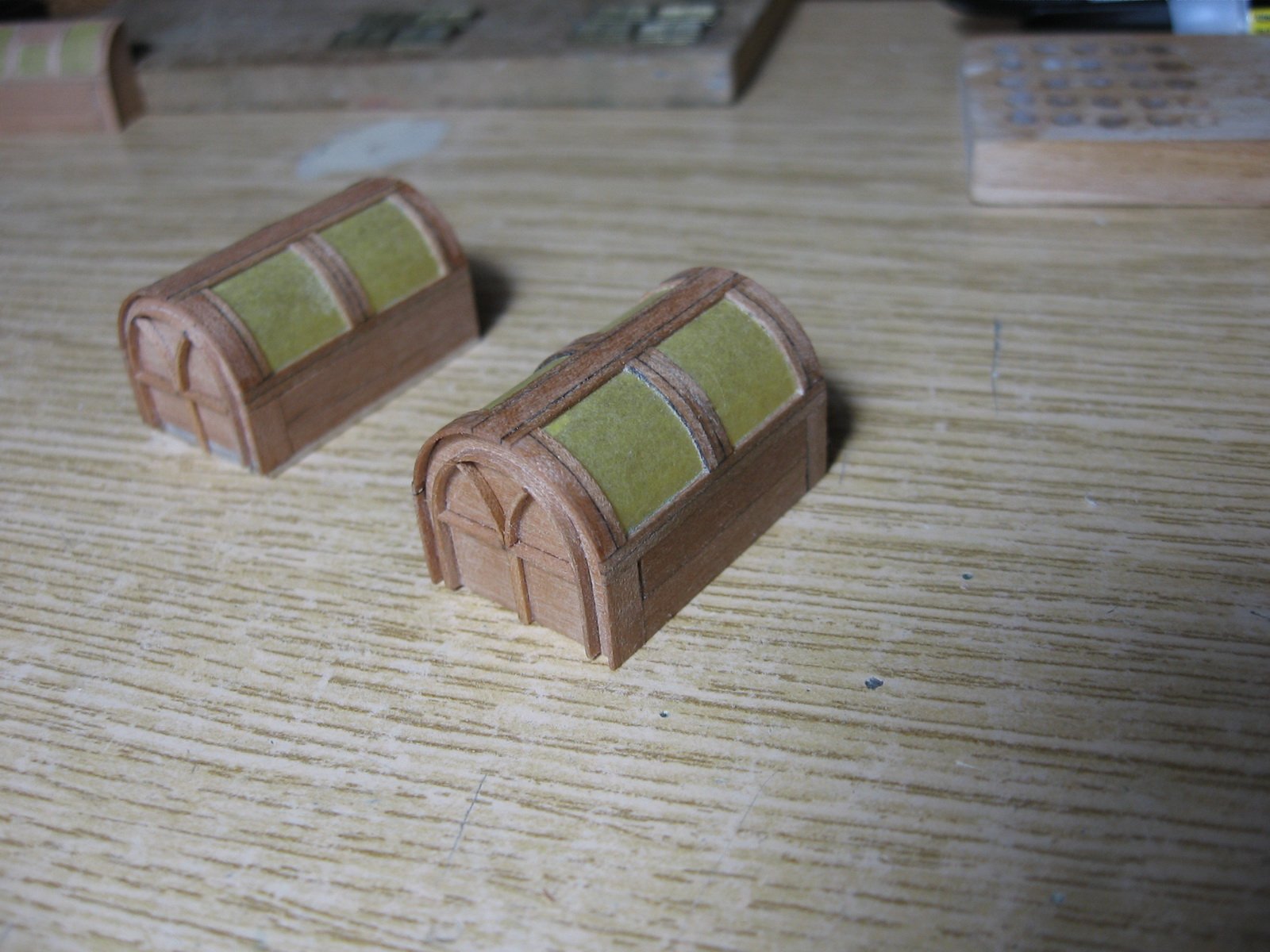
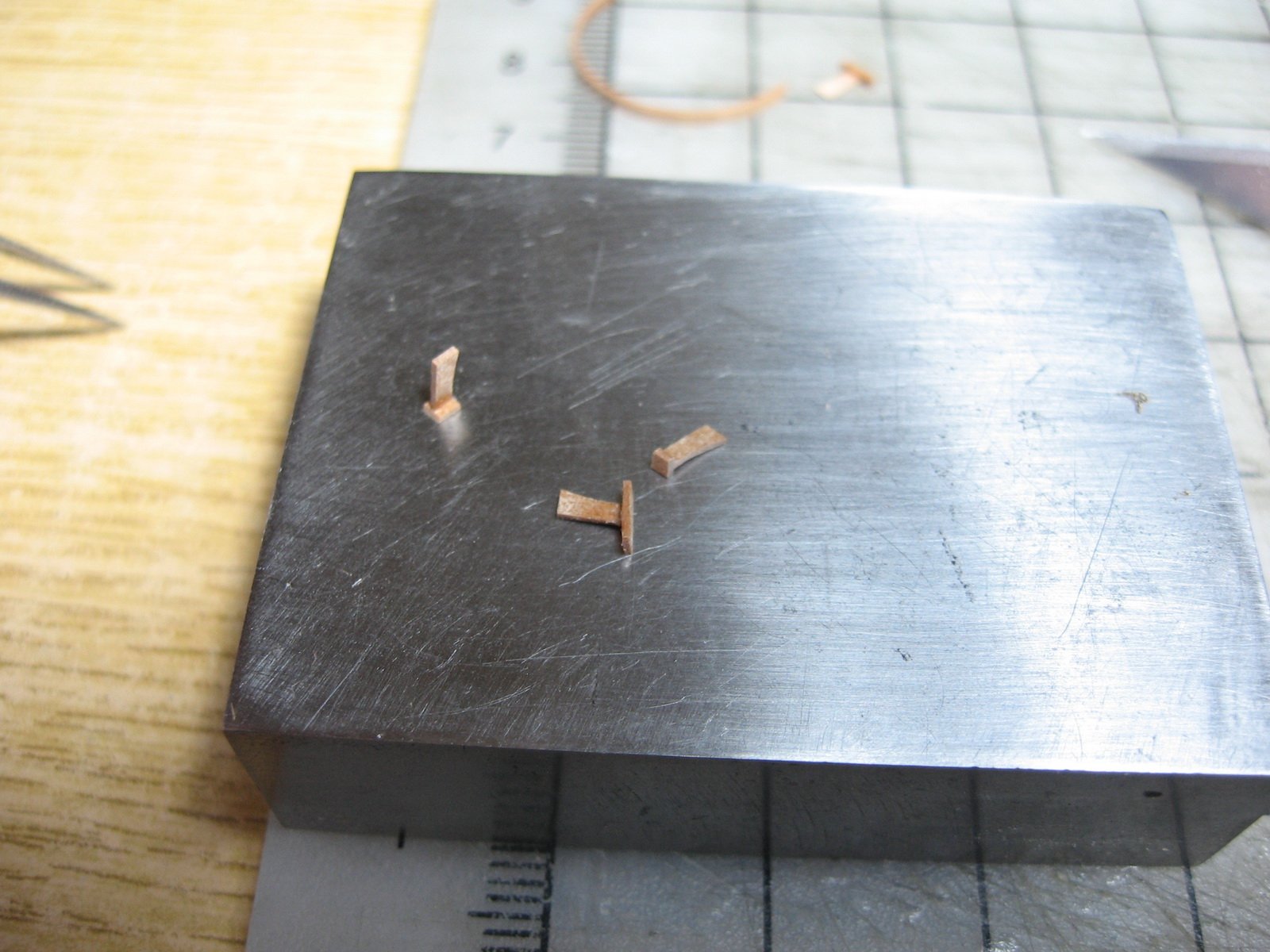
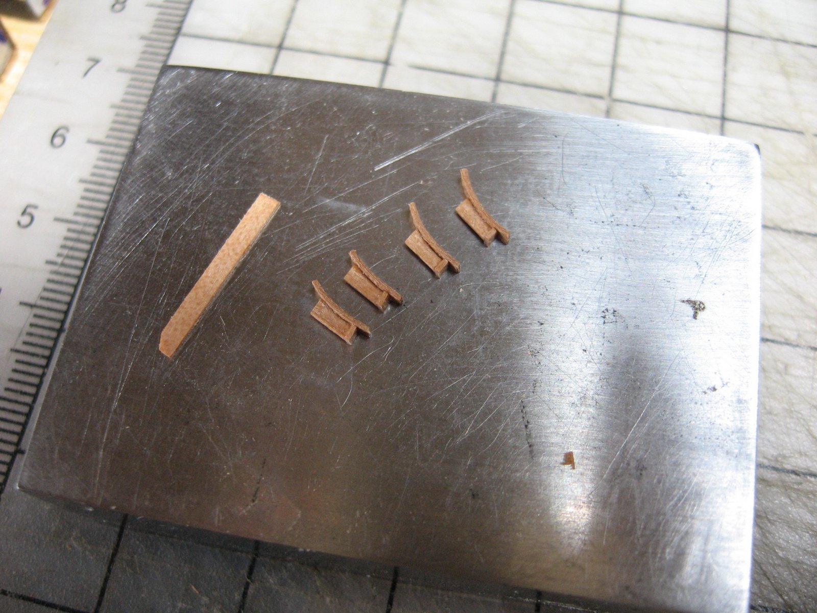
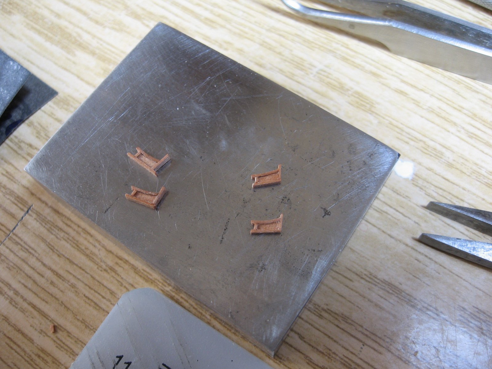
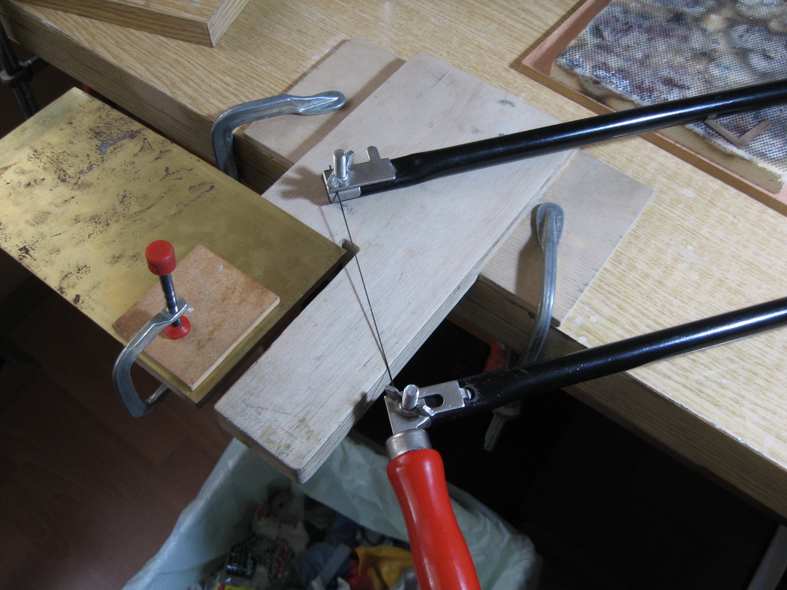
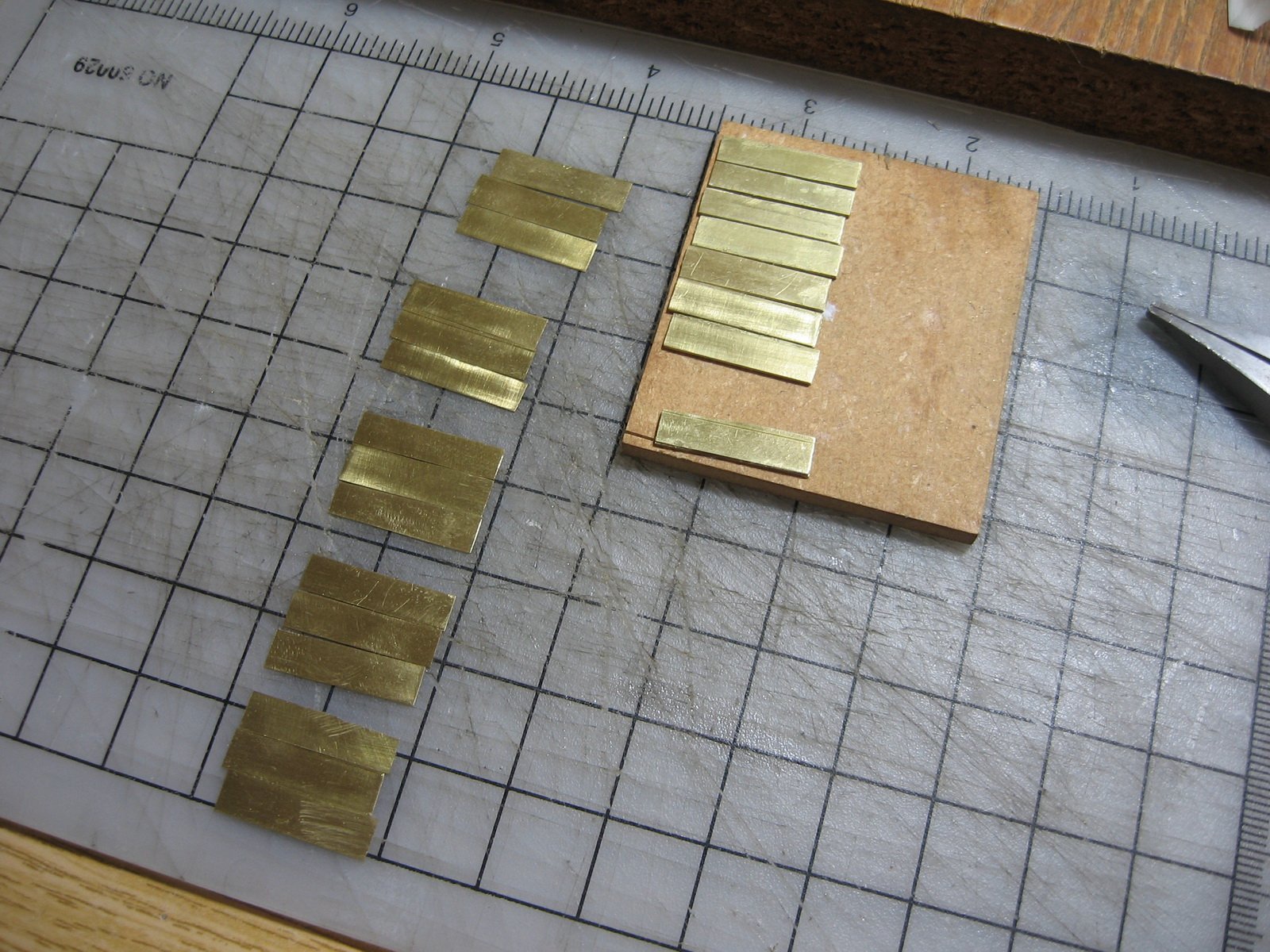
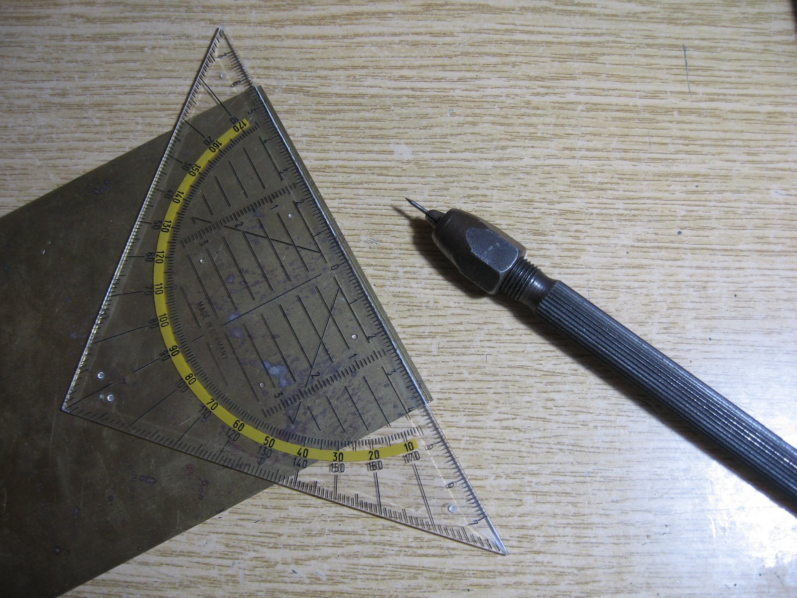
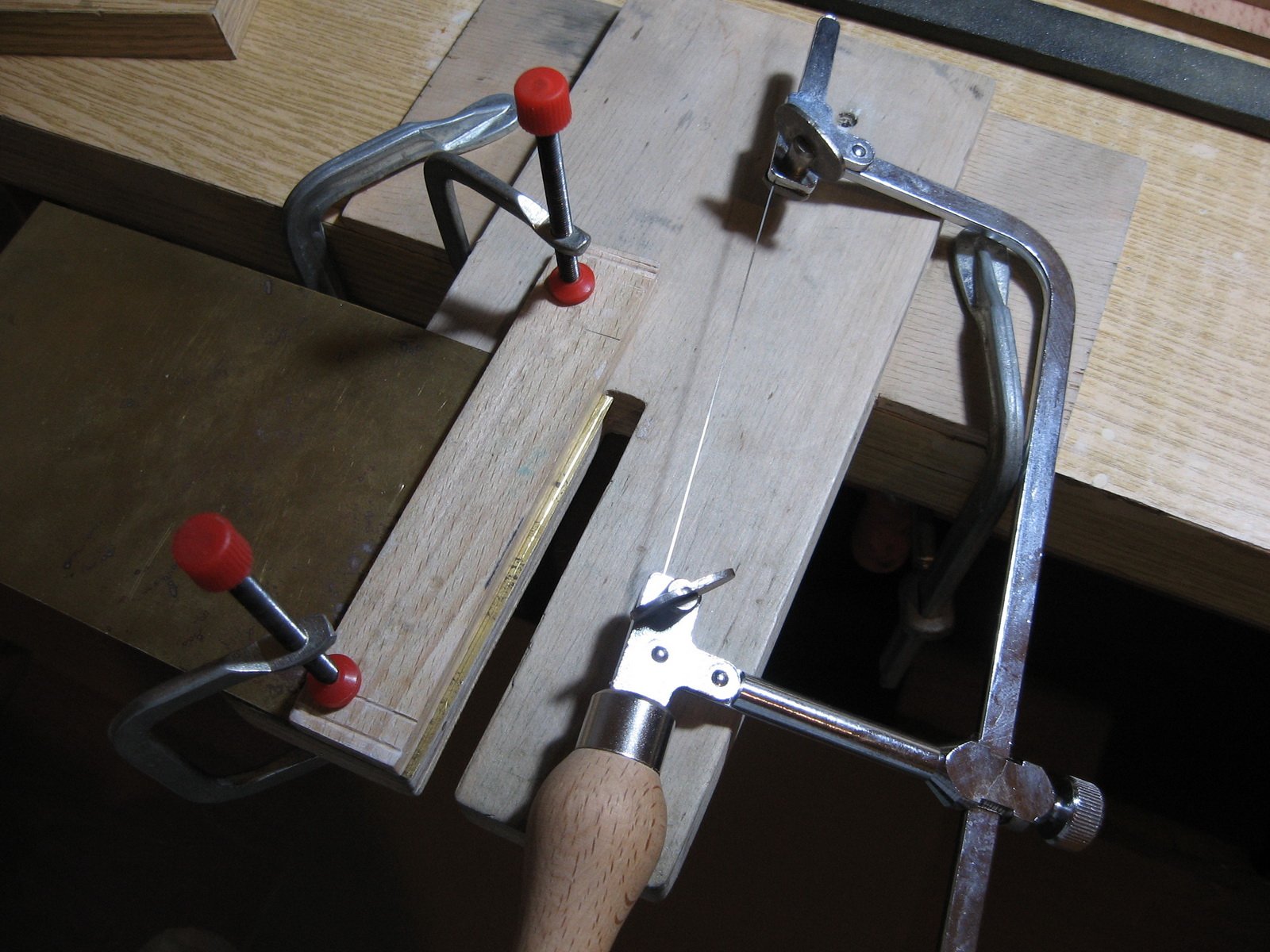
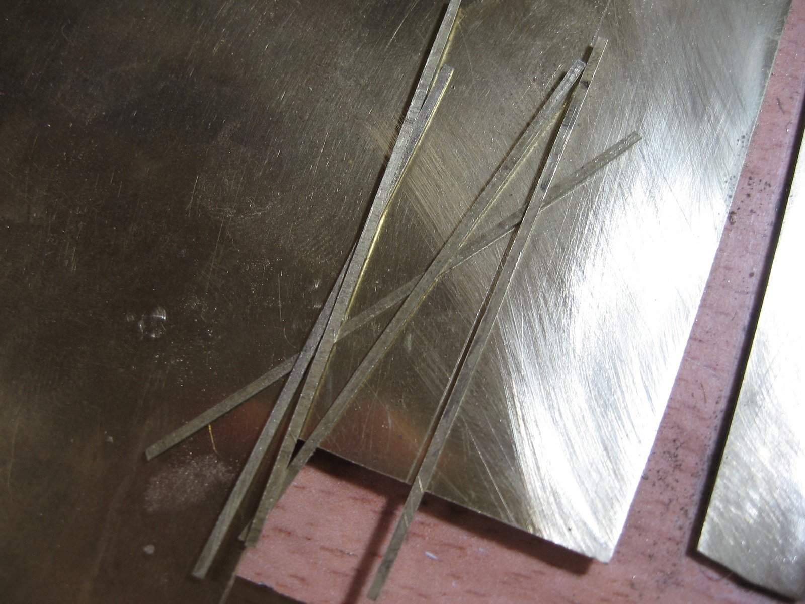
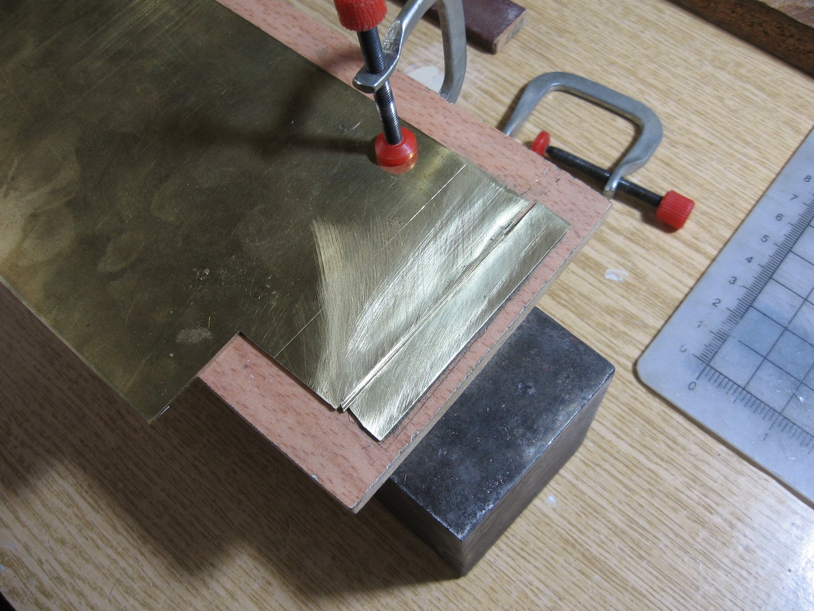
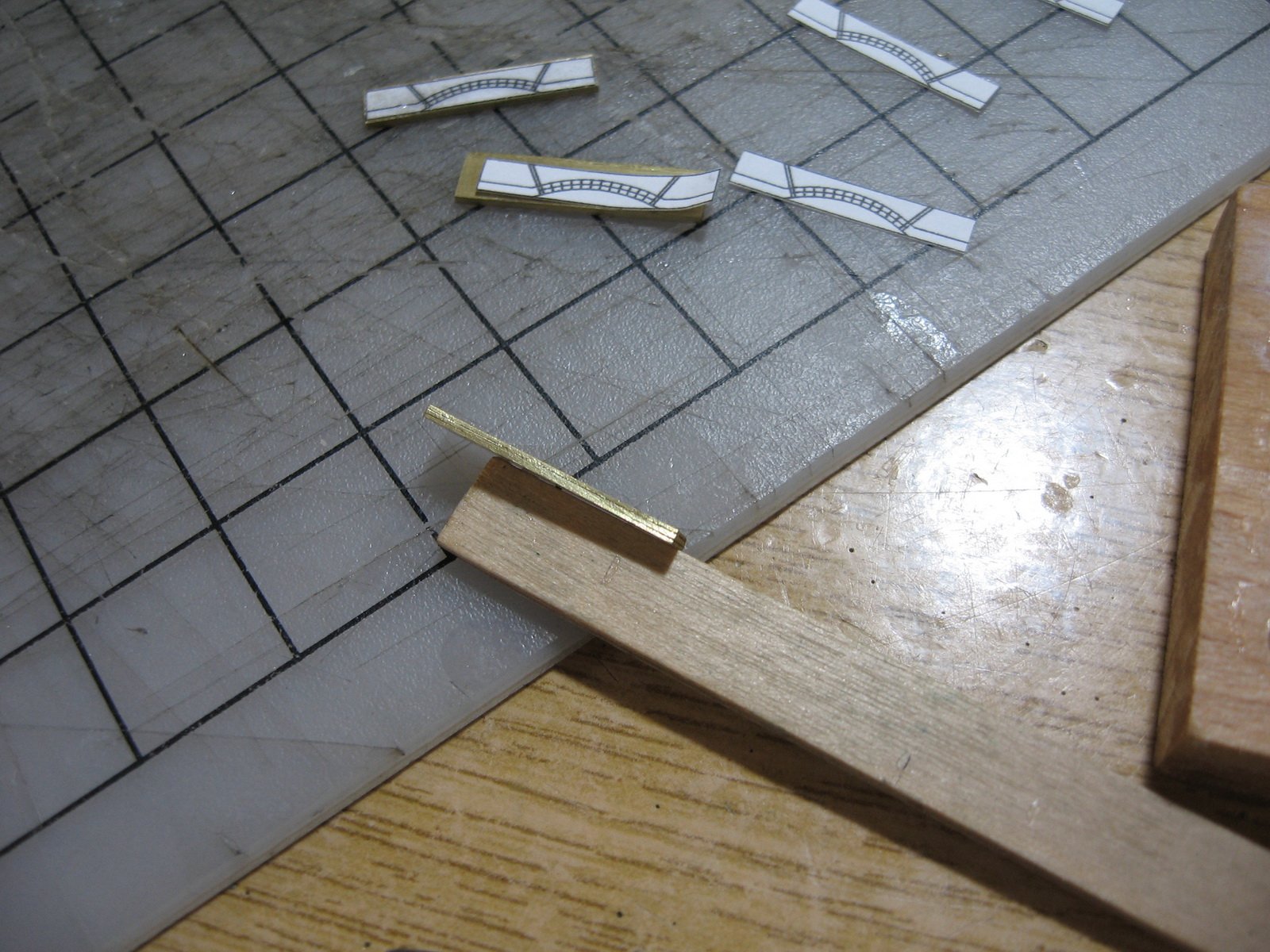
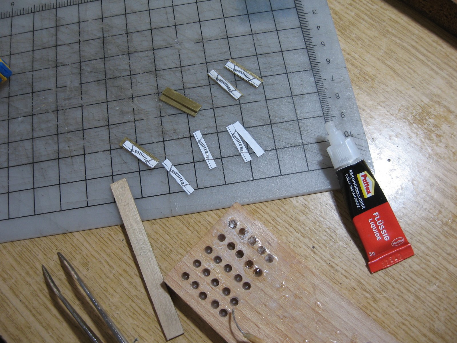
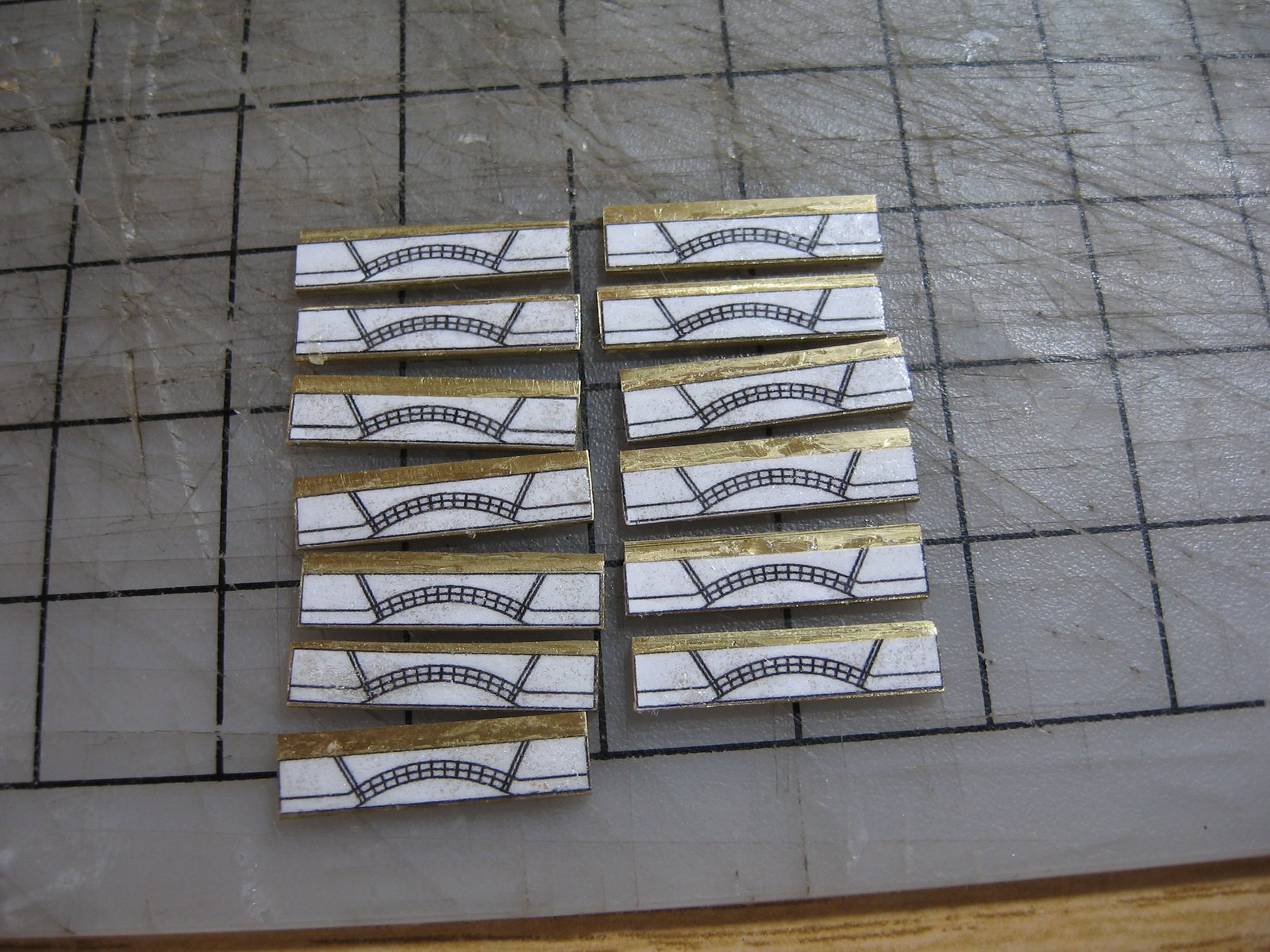
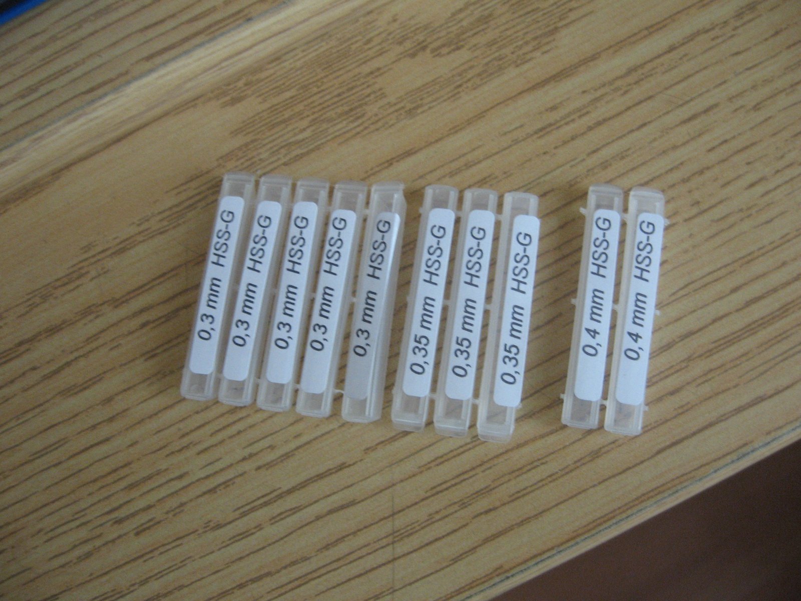
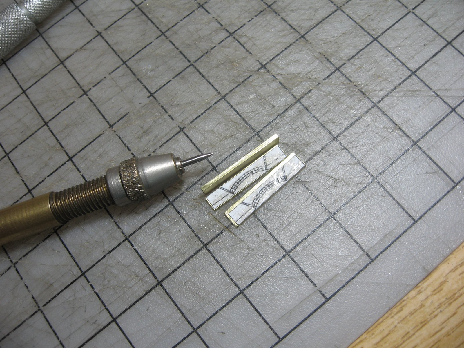
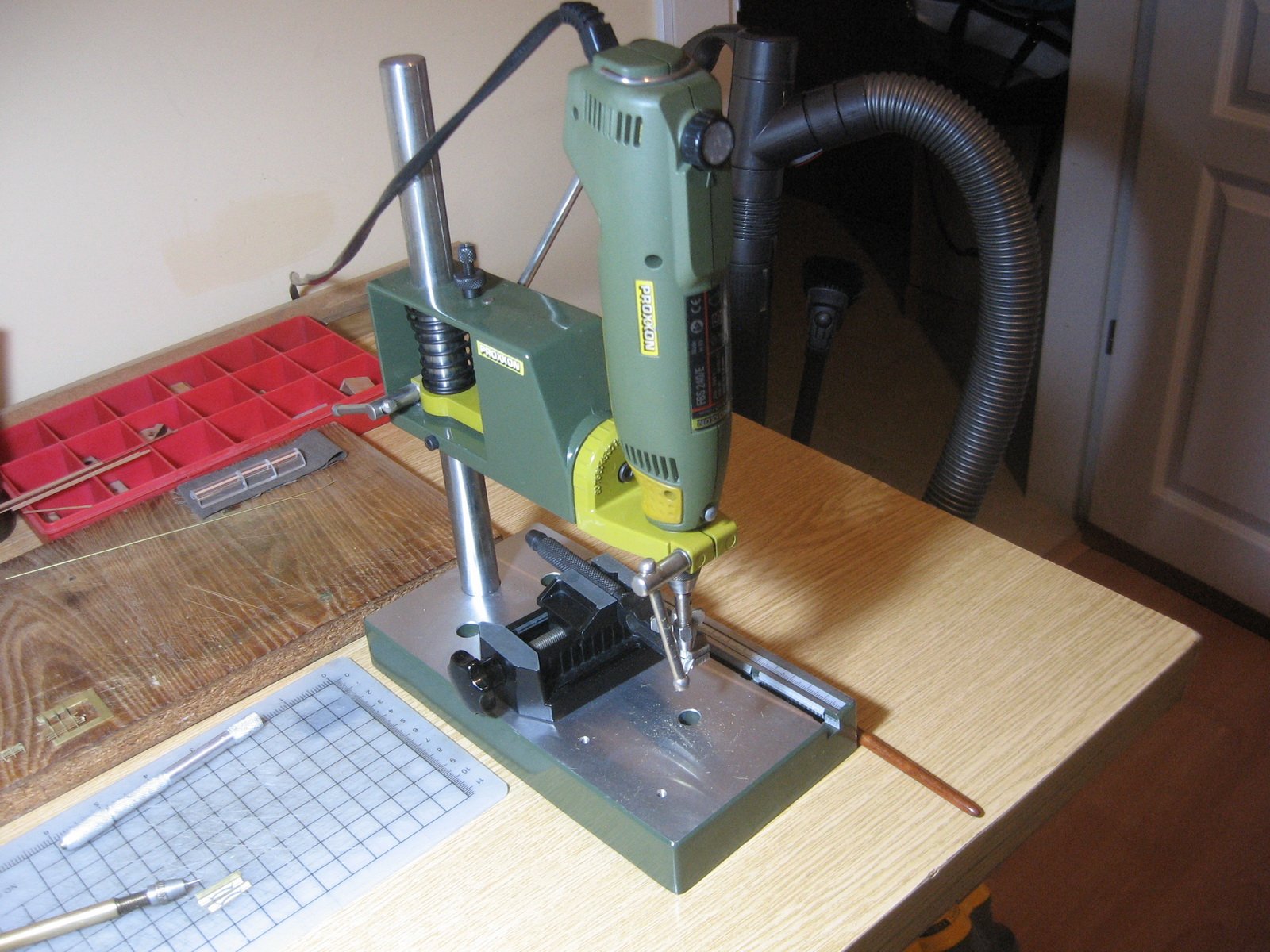
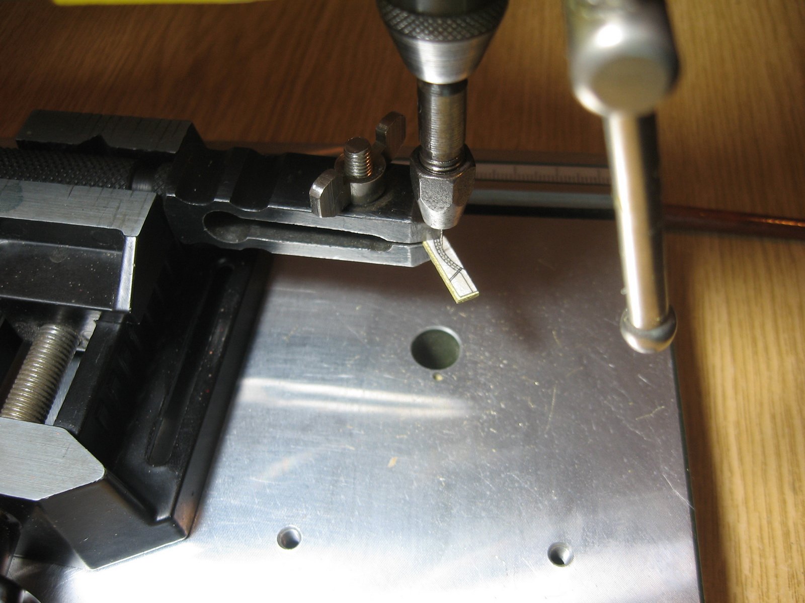
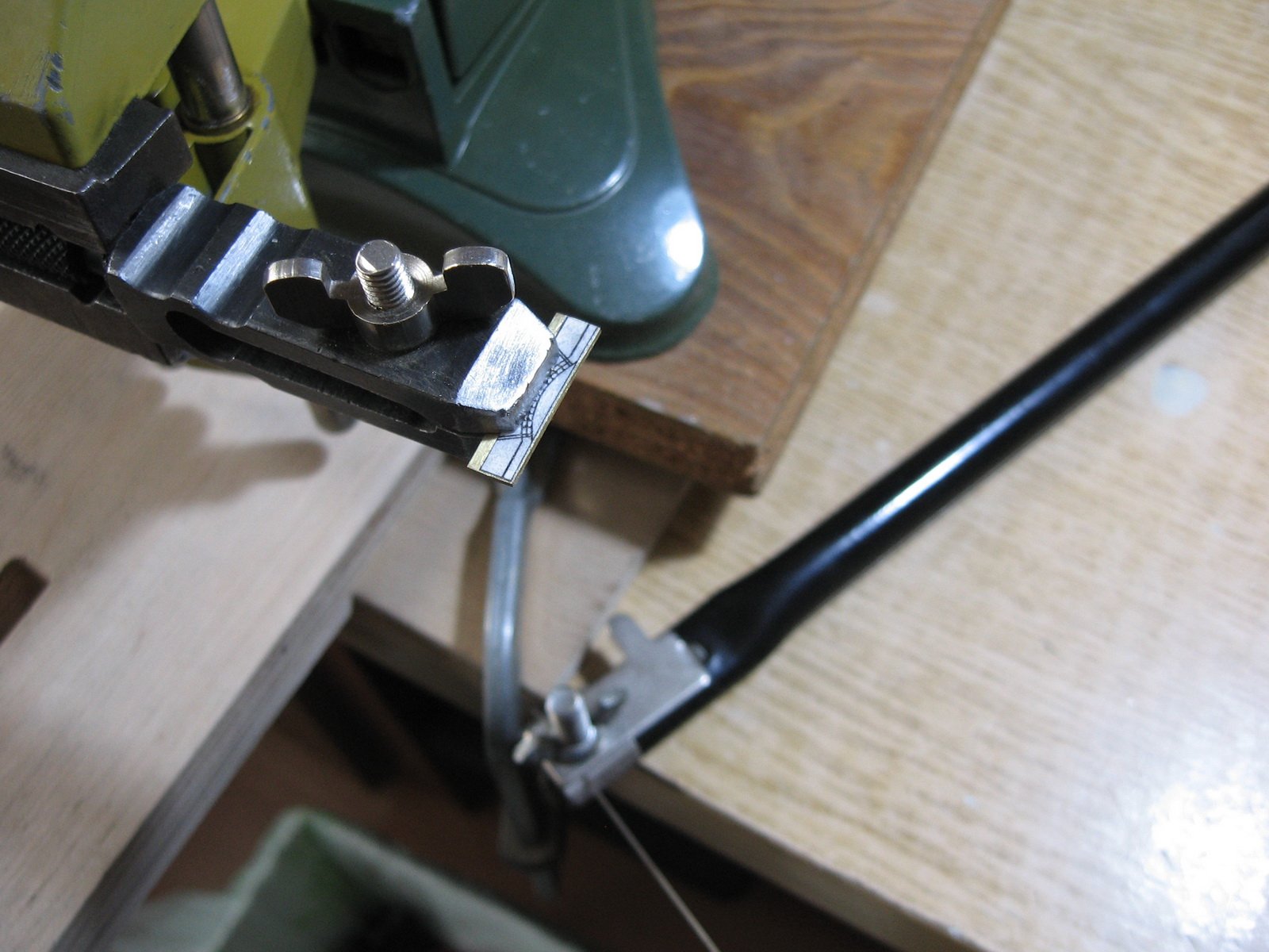
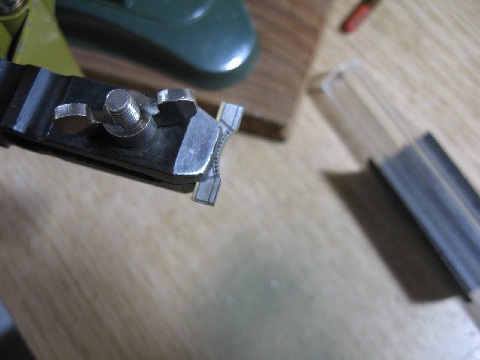
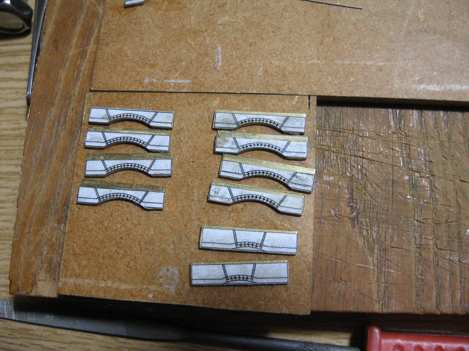
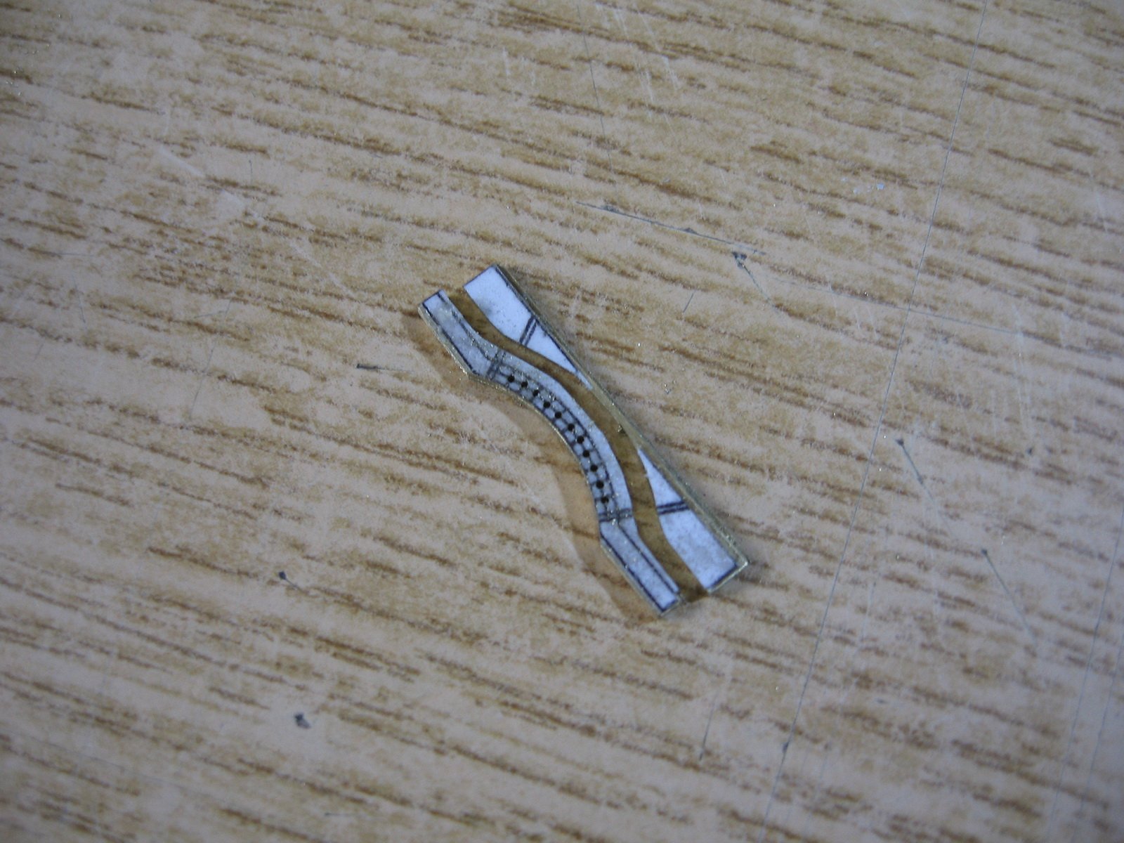
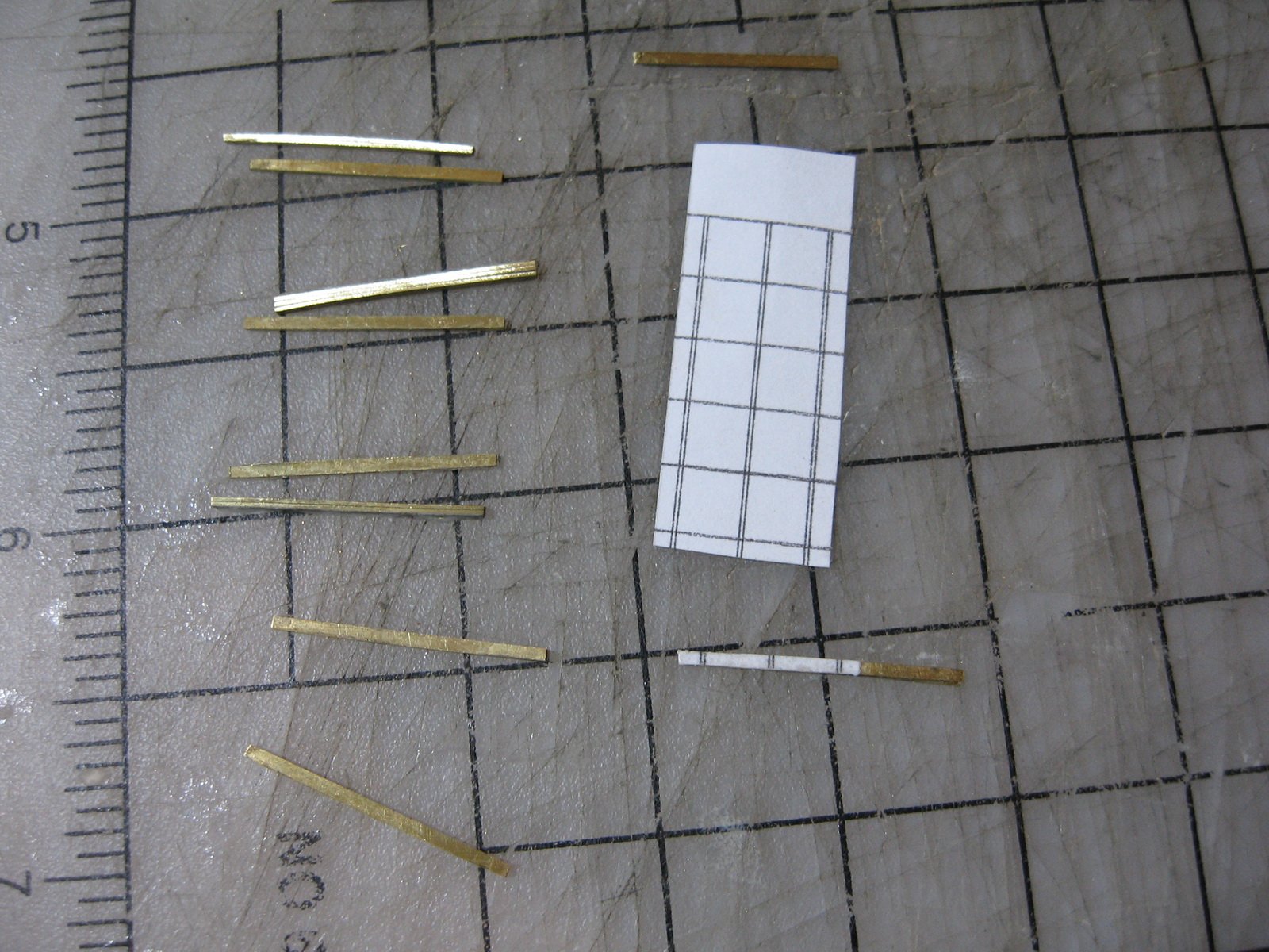
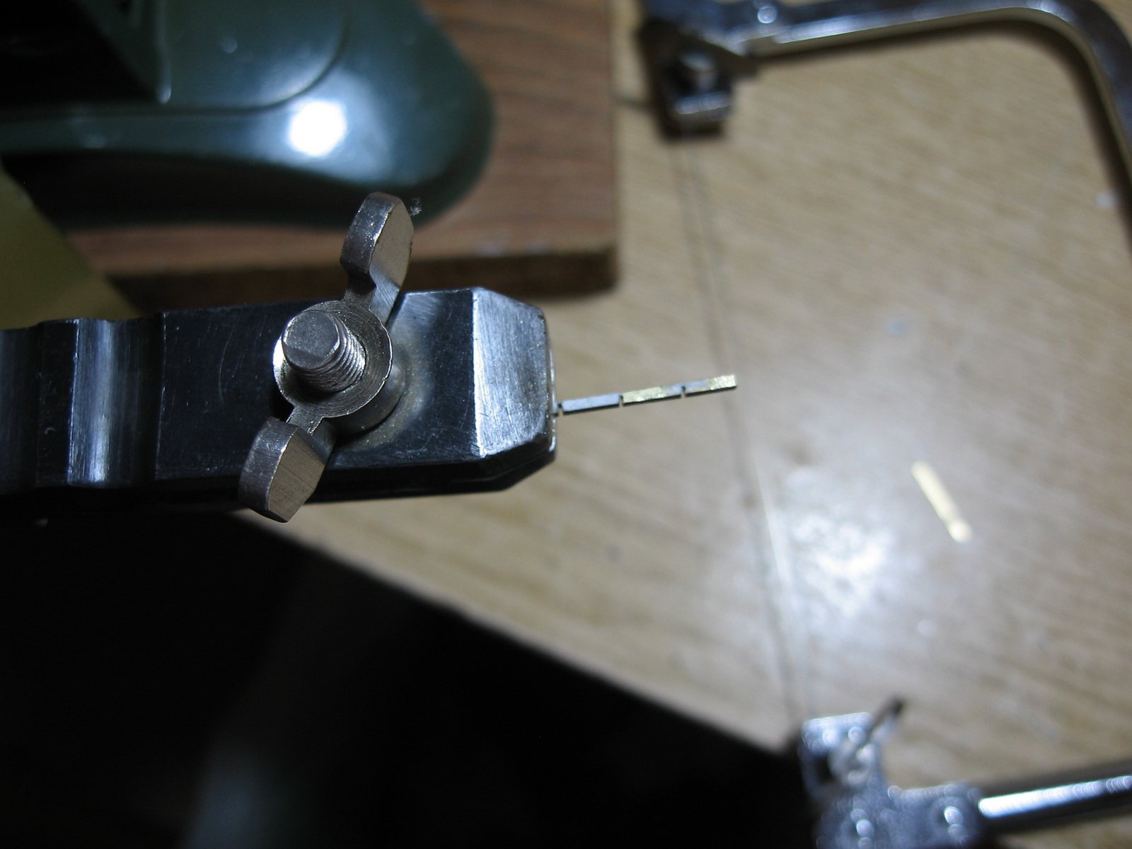
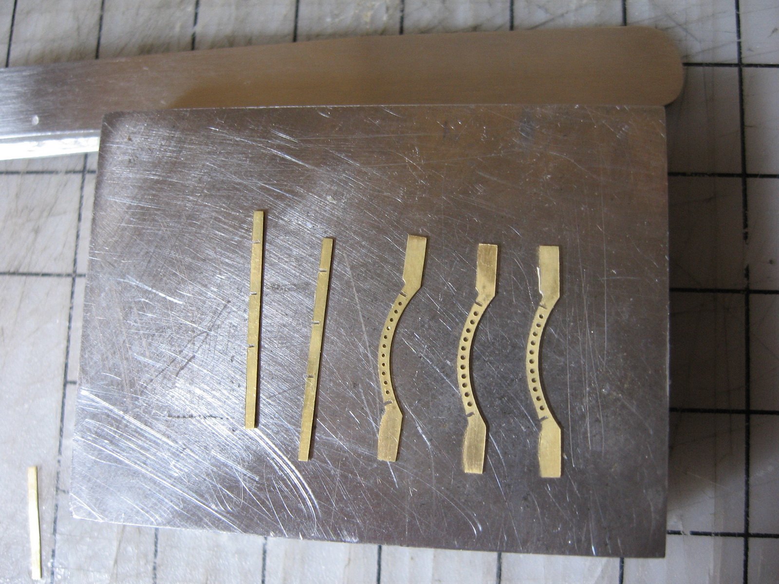
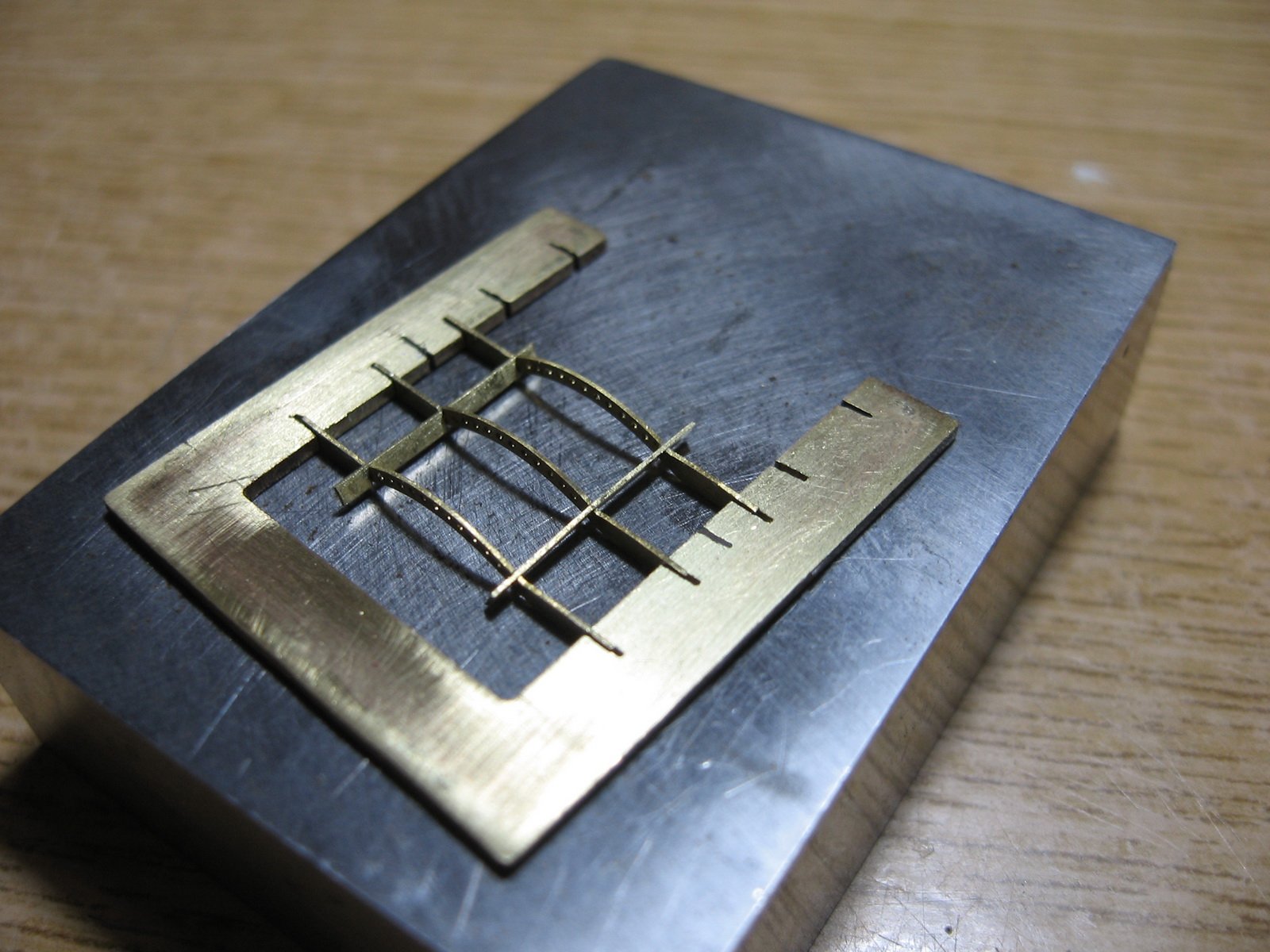
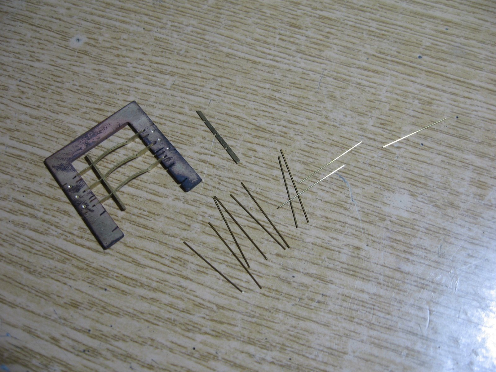
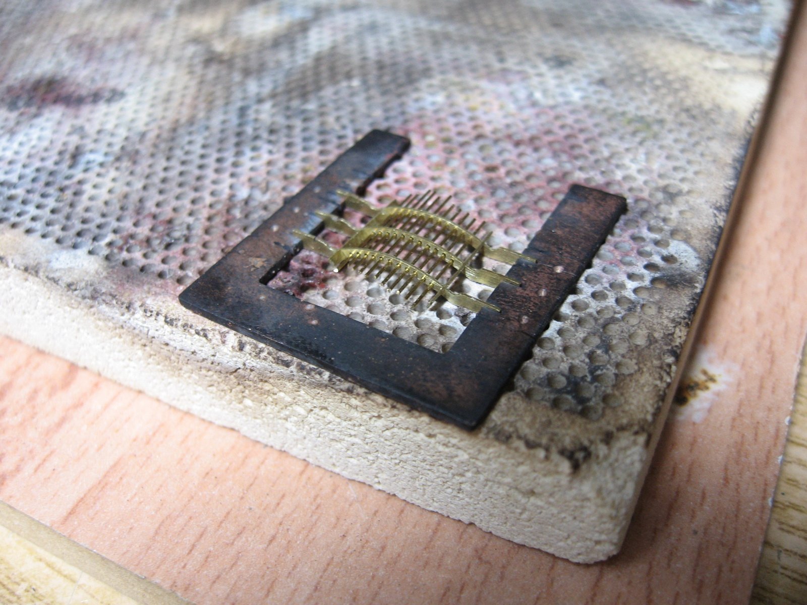
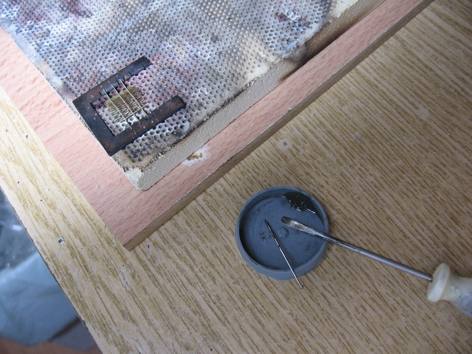
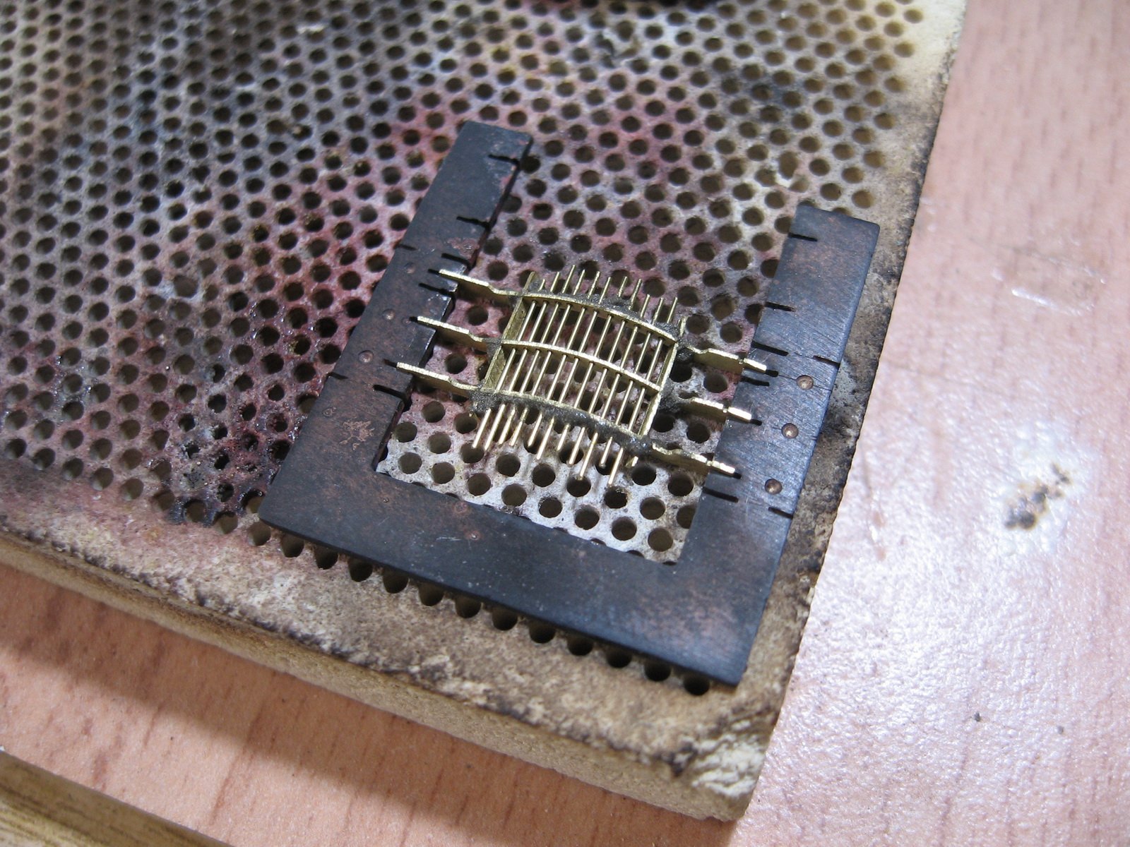
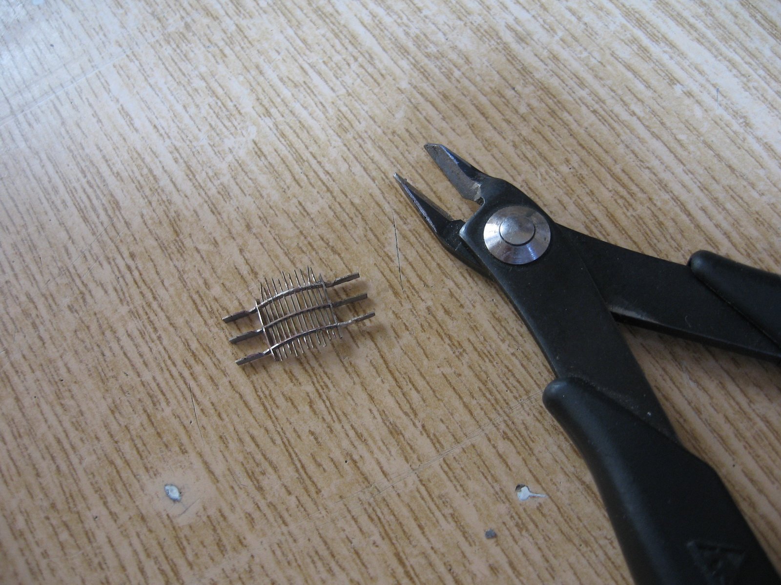
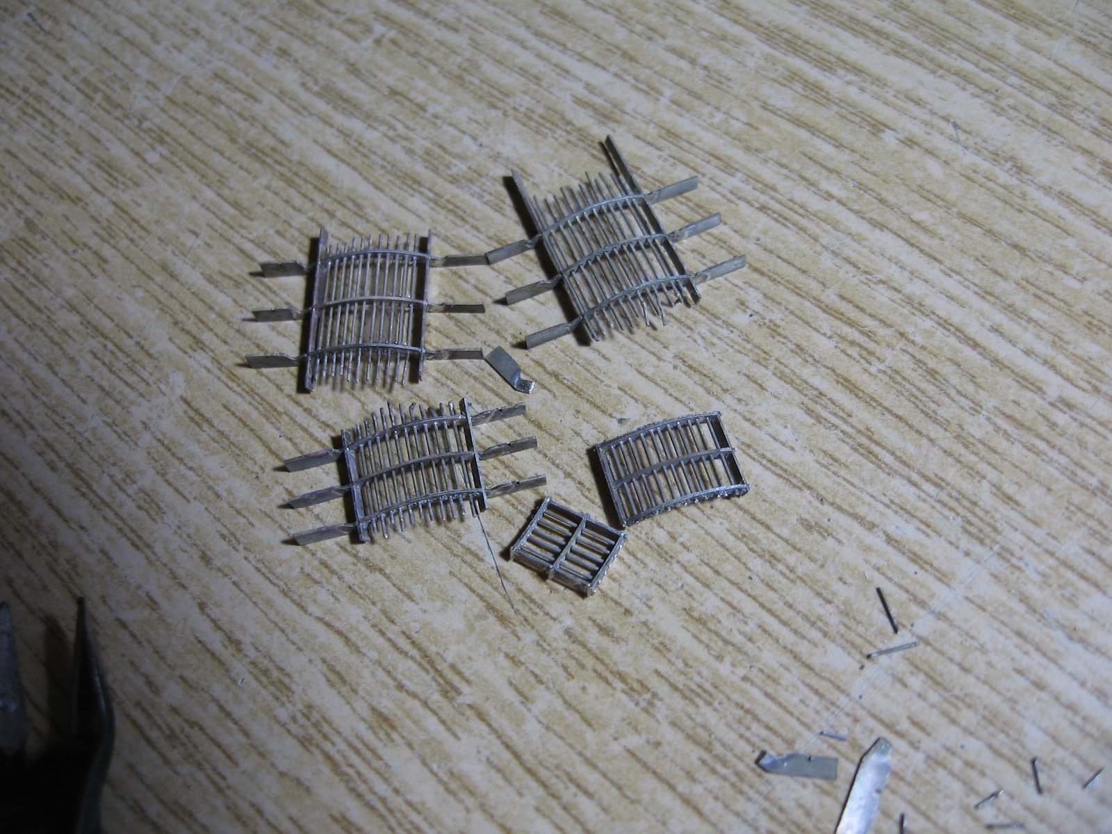
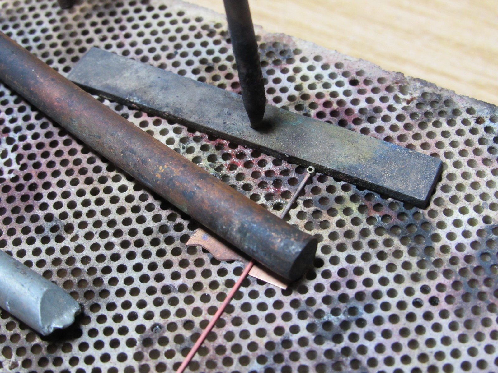
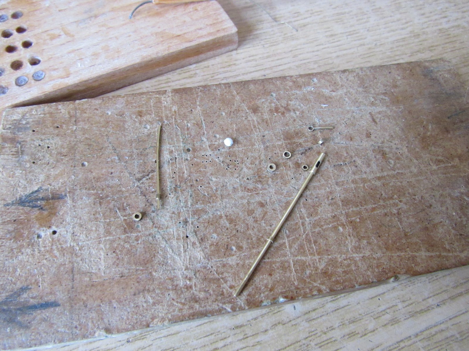
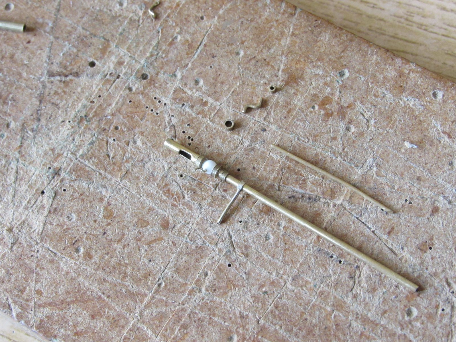
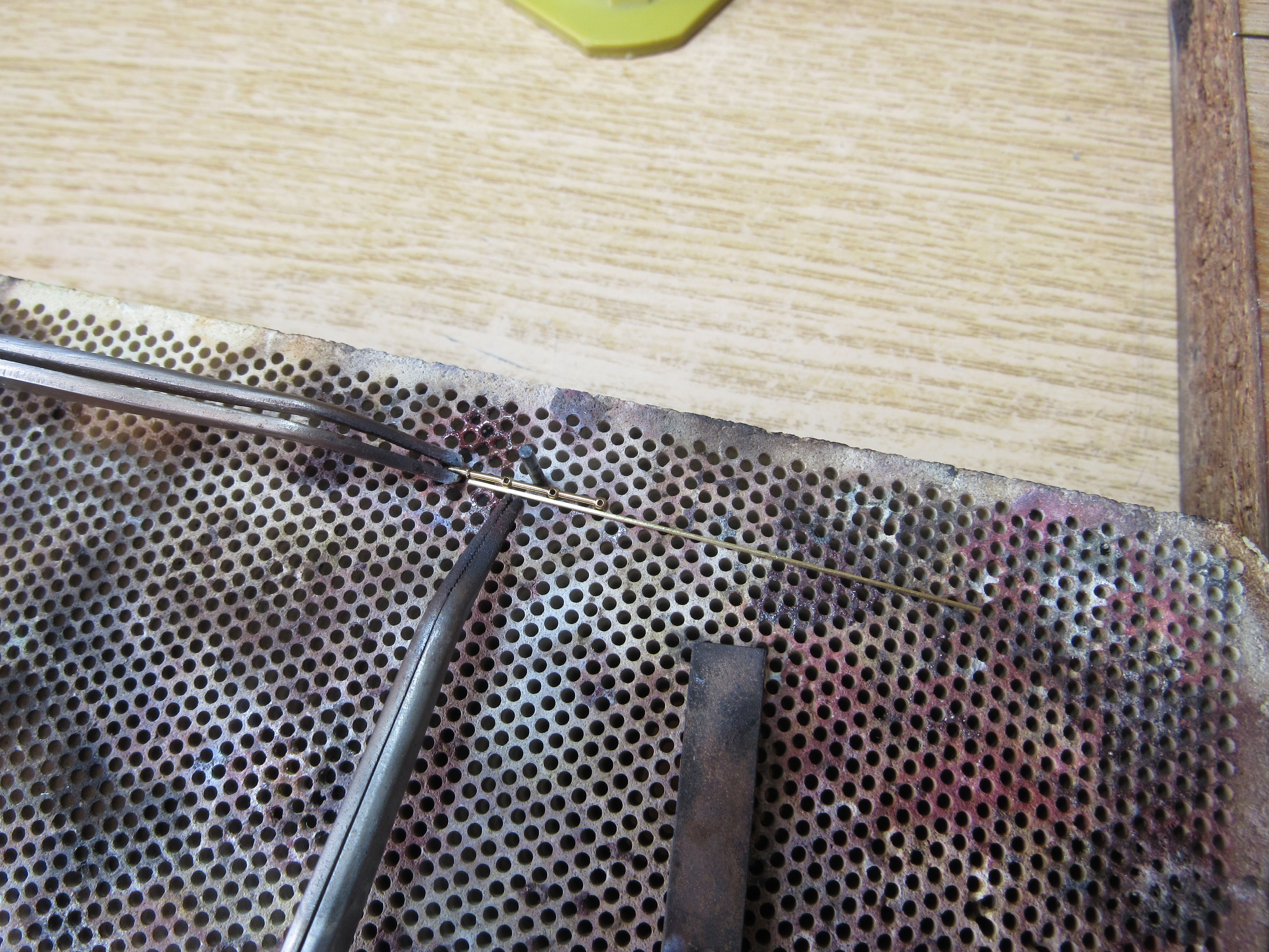
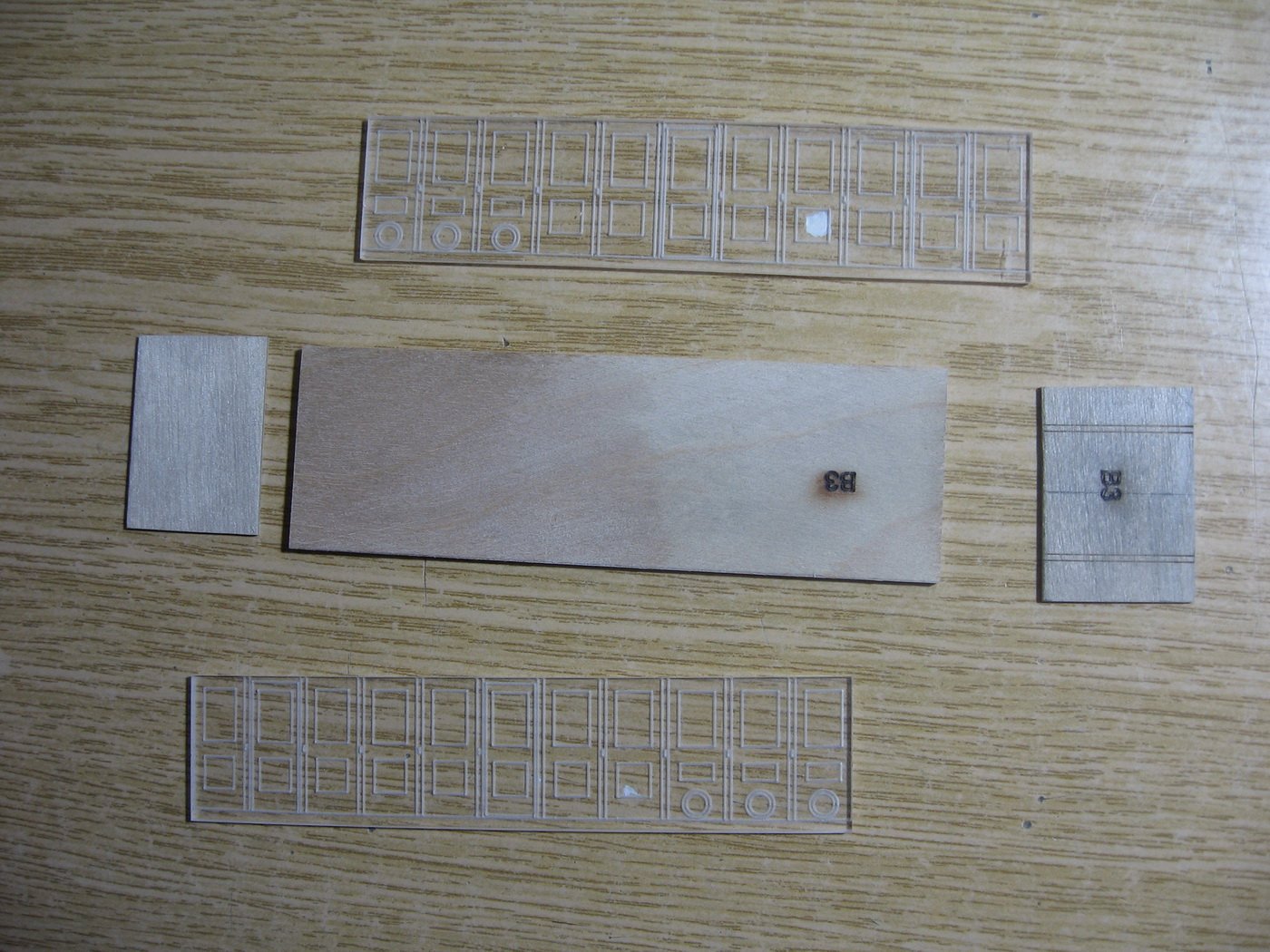
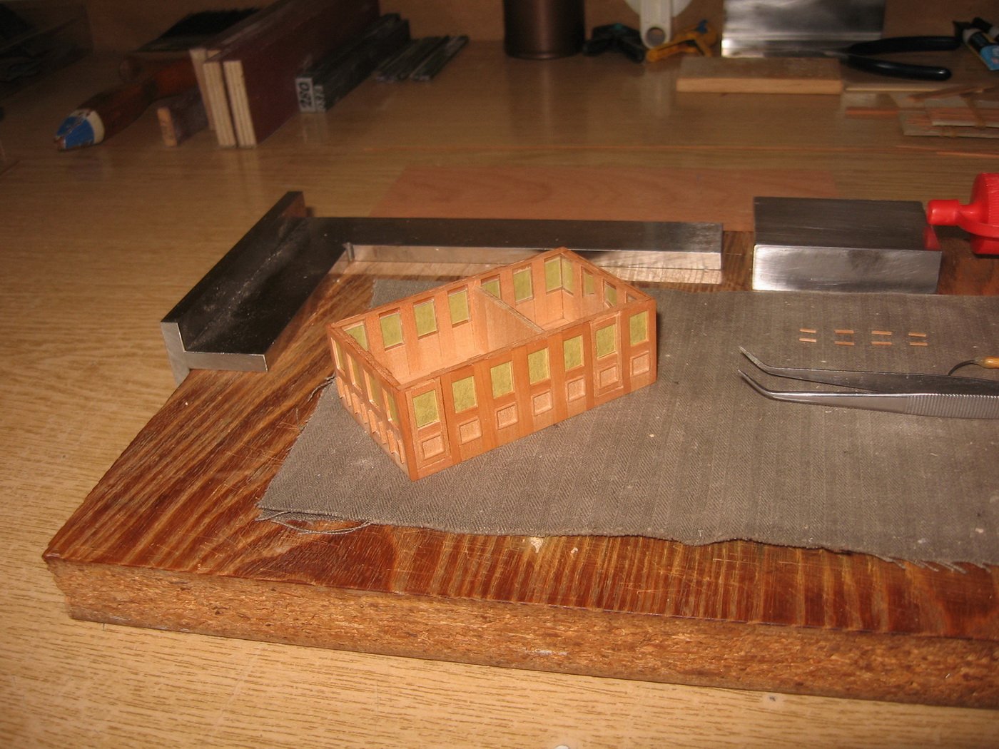
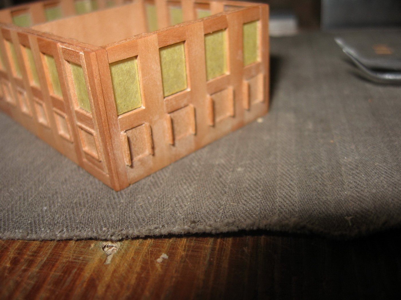
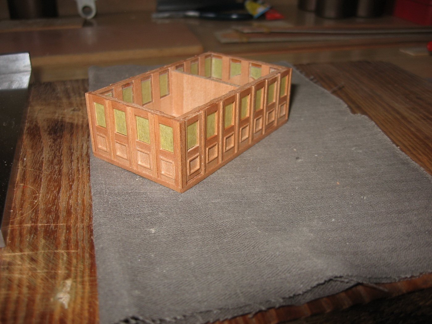
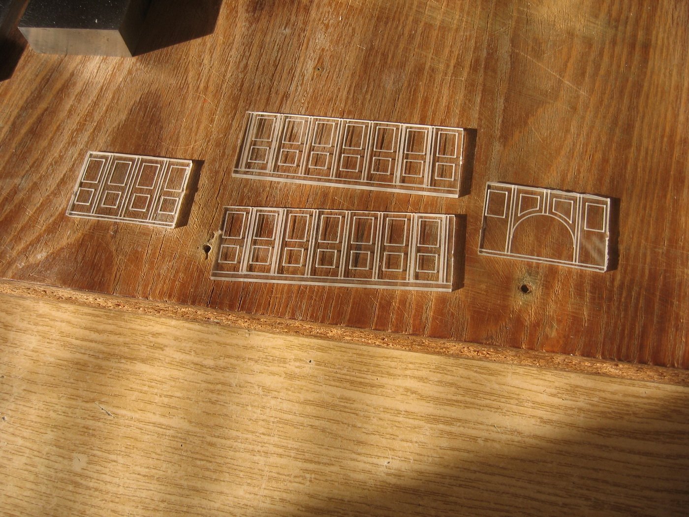
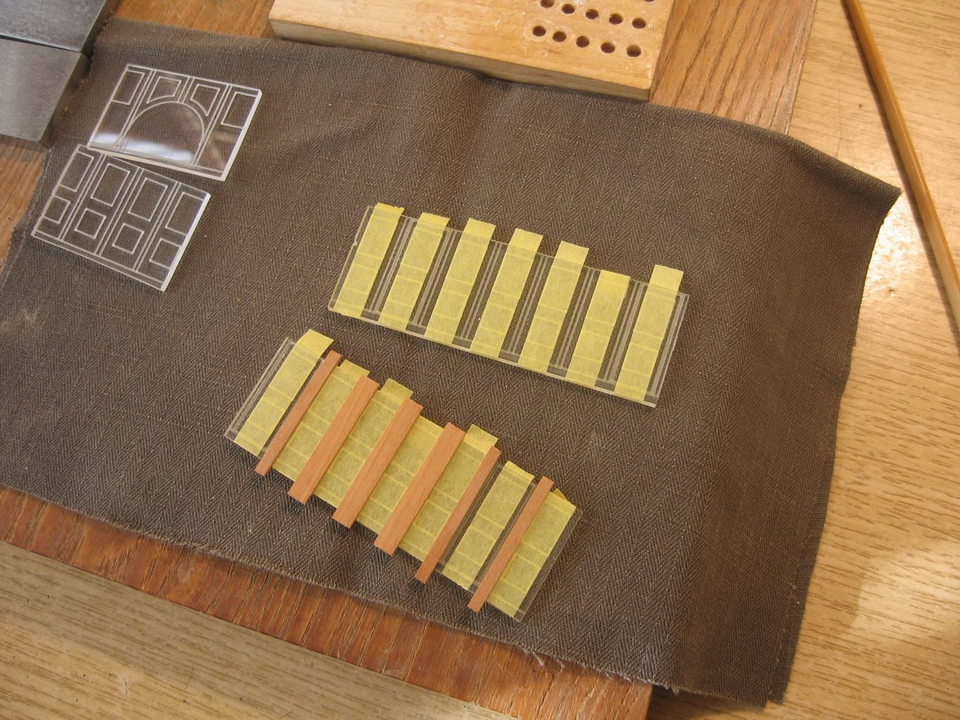
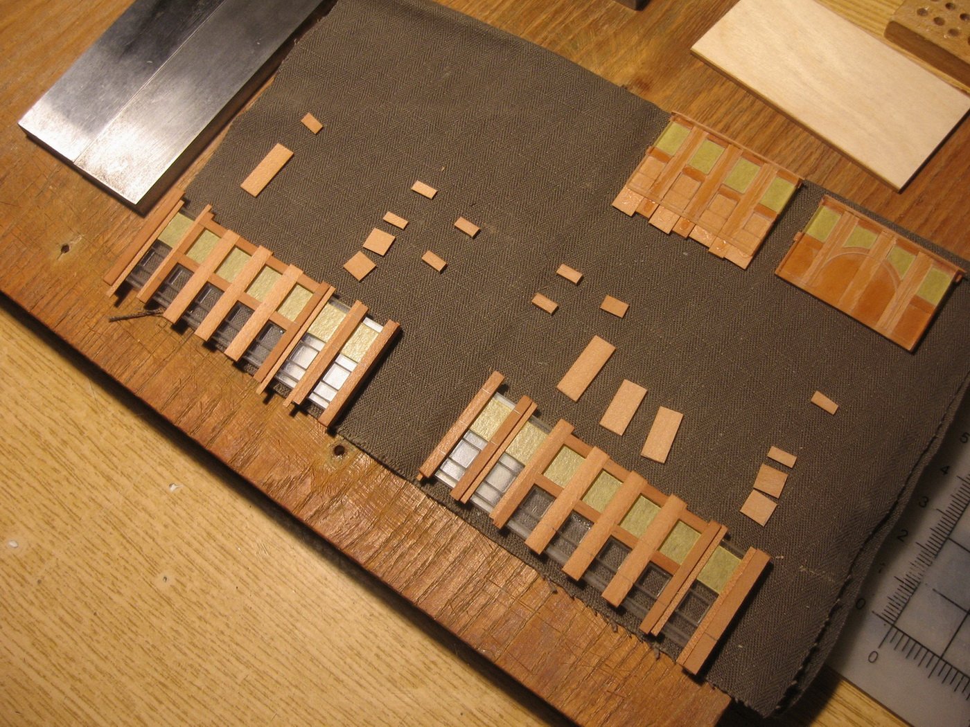
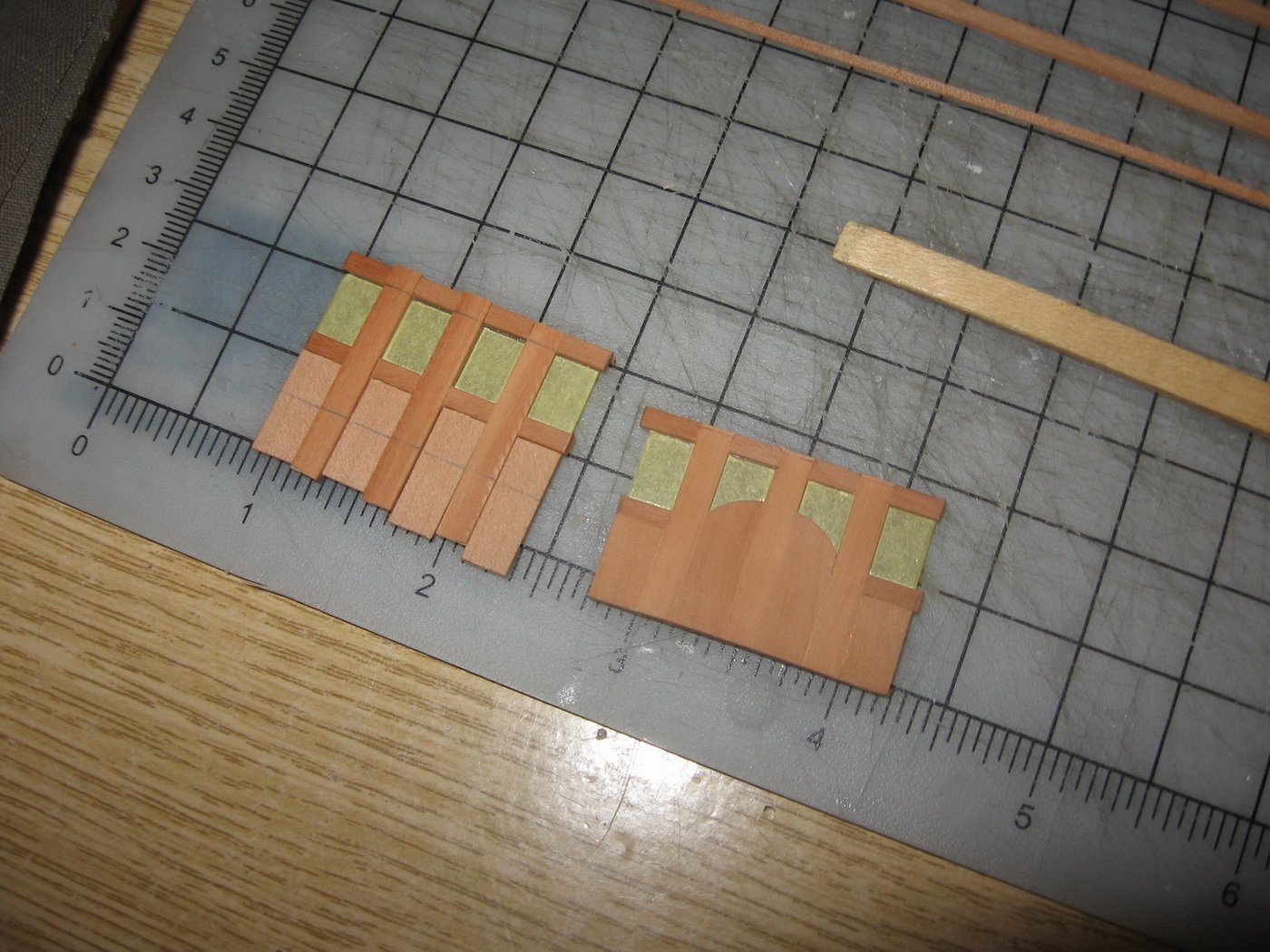
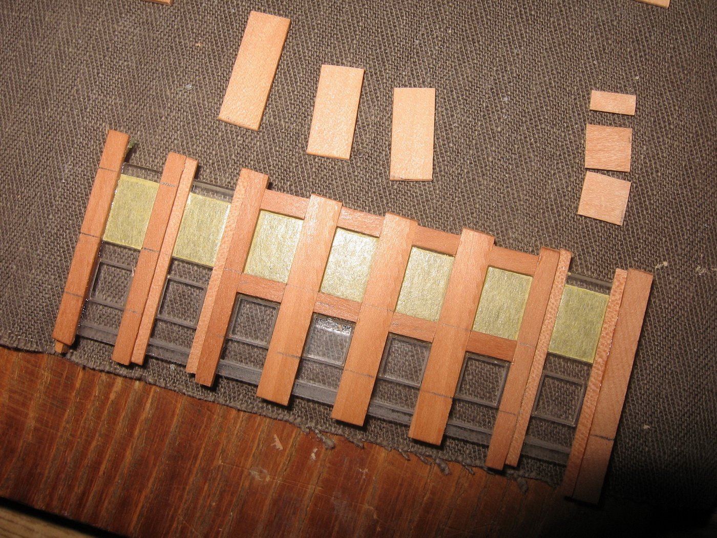
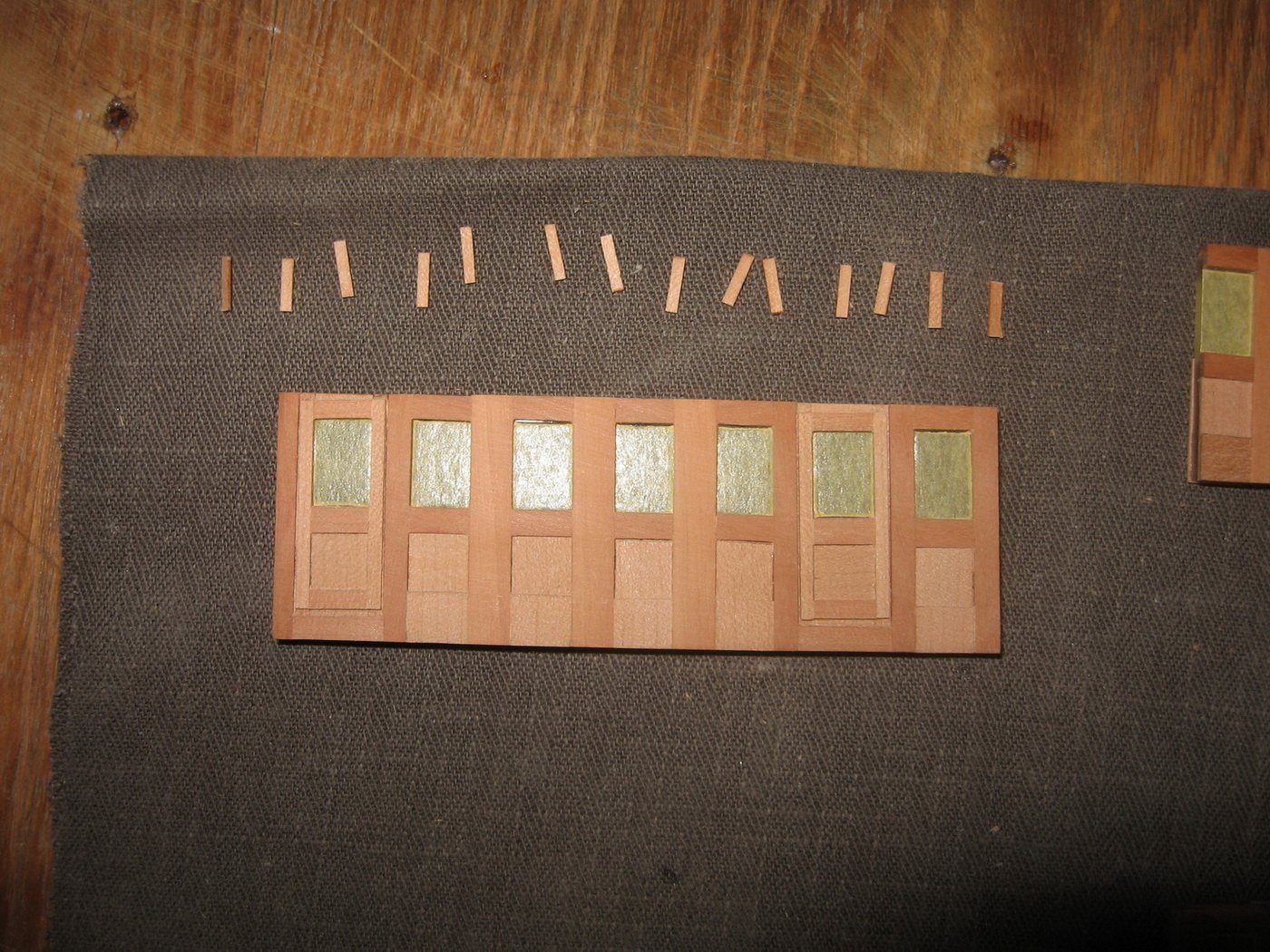
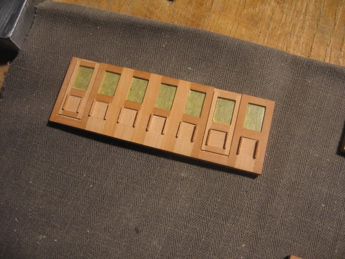
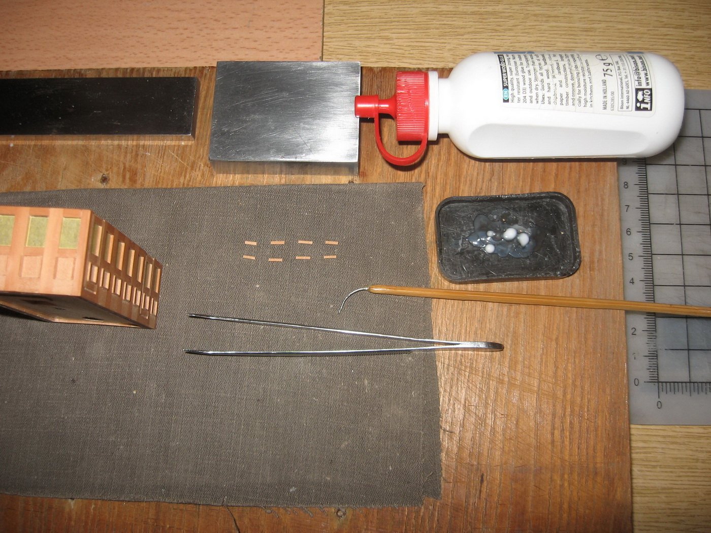
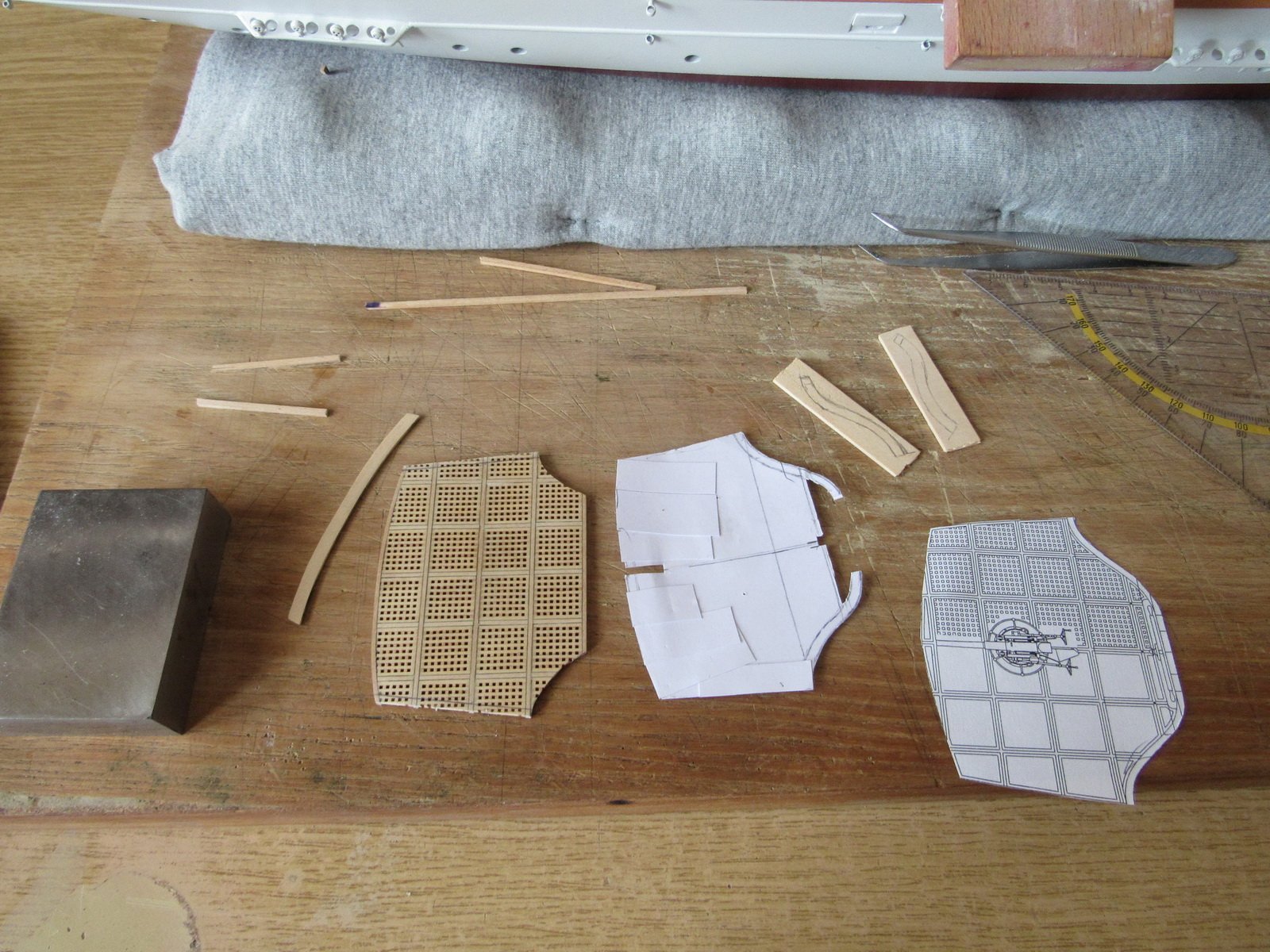
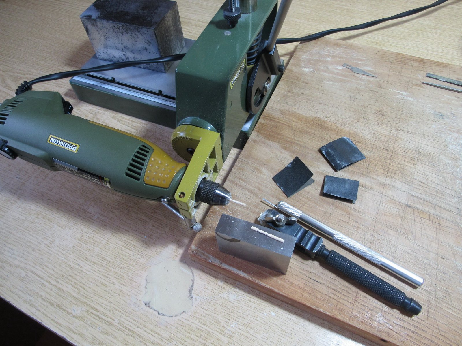
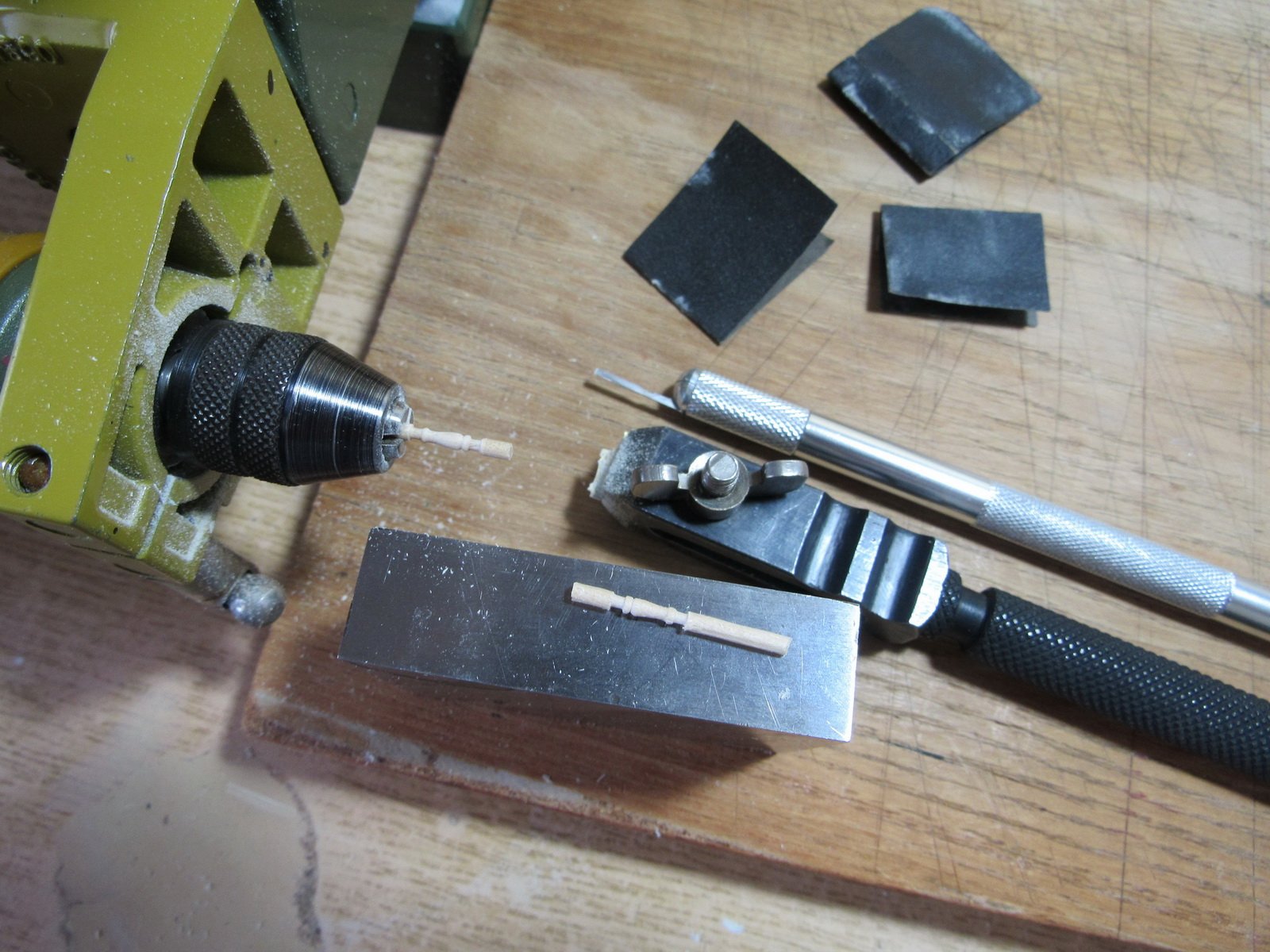
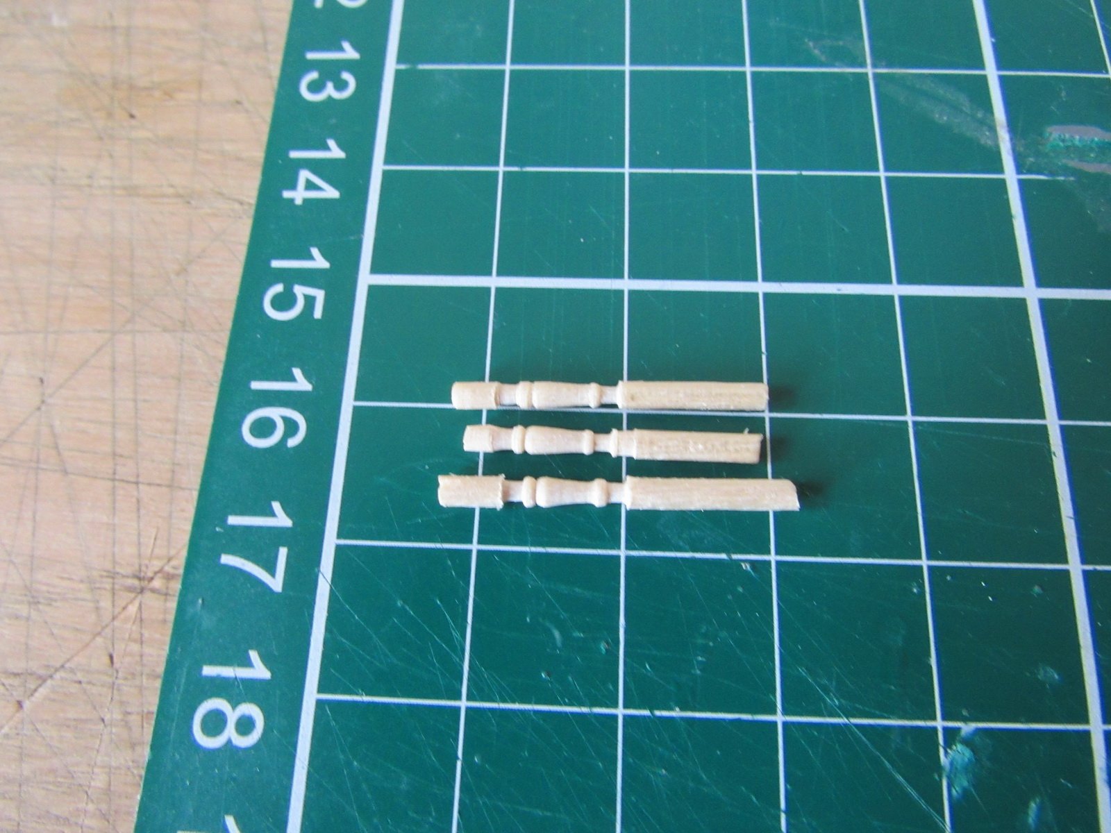
Yes, here are more info/photos of my method of photo etching. Istanbul Kayığı (Coastal trade vessel of Istanbul) 18 th c. Scale : 1/50, Scratch built (Build Log)
-
That's great. Thank you very much. A big relief for me. This ambiguous question was a bother for me. 👍