


Garward
-
Posts
1,572 -
Joined
-
Last visited
Content Type
Profiles
Forums
Gallery
Events
Everything posted by Garward
-

MONTANES by Garward - OcCre
Garward replied to Garward's topic in - Kit build logs for subjects built from 1751 - 1800
Directing for sawn preparations if necessary it is easily cleaned (leans back) for limits of a working surface of a table – for this purpose to unscrew the screw of a back clamp (a photo 35, the screw lies on a network box) enough. If to turn off one more of the nuts keeping an axis of a forward clamp (a photo 36) and to put forward an axis the directing will fall below a working surface of a table. On a photo 37 the back end directing with a clamp and the Г-shaped emphasis from a steel of 3 mm is shown.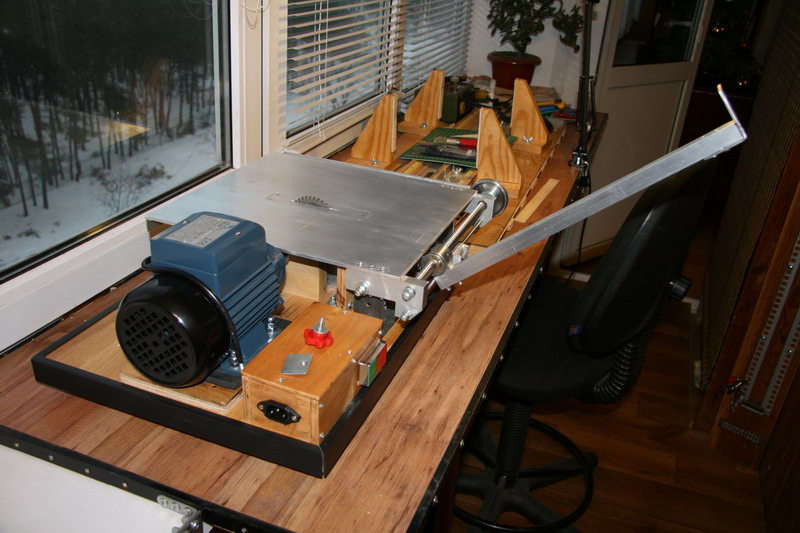
-
MONTANES by Garward - OcCre
Garward replied to Garward's topic in - Kit build logs for subjects built from 1751 - 1800
Continuation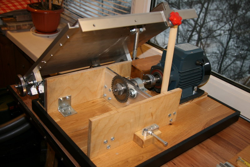
-
MONTANES by Garward - OcCre
Garward replied to Garward's topic in - Kit build logs for subjects built from 1751 - 1800
Continuation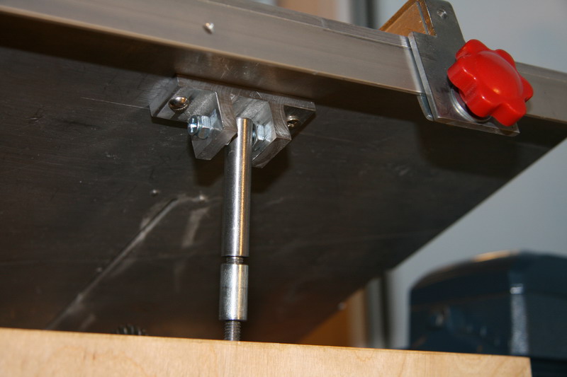
-
MONTANES by Garward - OcCre
Garward replied to Garward's topic in - Kit build logs for subjects built from 1751 - 1800
Continuation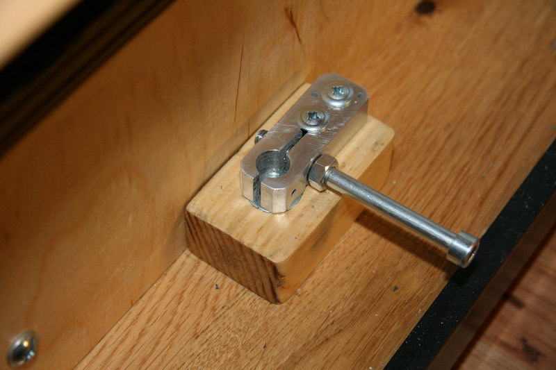
-
MONTANES by Garward - OcCre
Garward replied to Garward's topic in - Kit build logs for subjects built from 1751 - 1800
On a photo 31 - 34 the design for start change a disk by table lifting is shown. The nut which is carrying out lifting, is fixed in a holder from Д16Т by screw M6.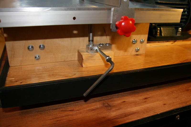
-
MONTANES by Garward - OcCre
Garward replied to Garward's topic in - Kit build logs for subjects built from 1751 - 1800
Continuation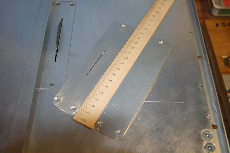
-
MONTANES by Garward - OcCre
Garward replied to Garward's topic in - Kit build logs for subjects built from 1751 - 1800
Continuation
-
MONTANES by Garward - OcCre
Garward replied to Garward's topic in - Kit build logs for subjects built from 1751 - 1800
Continuation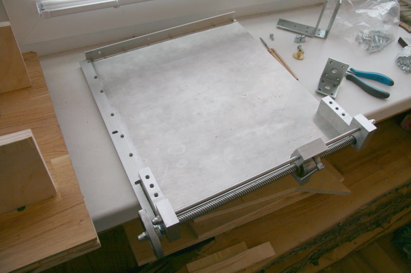
-
MONTANES by Garward - OcCre
Garward replied to Garward's topic in - Kit build logs for subjects built from 1751 - 1800
On a photo 27 - 30 the design a table is shown: actually a table 380х330х5 mm from Д16Т, a corner from Д16Т on a back part - directing for moving and fixing of a back part of an emphasis, a corner from Д16Т on a lateral part - for protractor moving (oblique-angled cutting).
-
MONTANES by Garward - OcCre
Garward replied to Garward's topic in - Kit build logs for subjects built from 1751 - 1800
Continuation That is shown on a photo 18 - 26, is the cutting block to which it is possible to attach easily tables of the various sizes and designs depending on requirements (for example, with the emphasis fixed on a surface for manufacturing of gratings, etc.). -
MONTANES by Garward - OcCre
Garward replied to Garward's topic in - Kit build logs for subjects built from 1751 - 1800
Continuation
-
MONTANES by Garward - OcCre
Garward replied to Garward's topic in - Kit build logs for subjects built from 1751 - 1800
On a photo 25 - 26 are shown cutting disks in diameter 63, 80 and 115 mm (the cores the sizes assumed to the use). In general the design is calculated on application of disks with the maximum diameter 160 mm.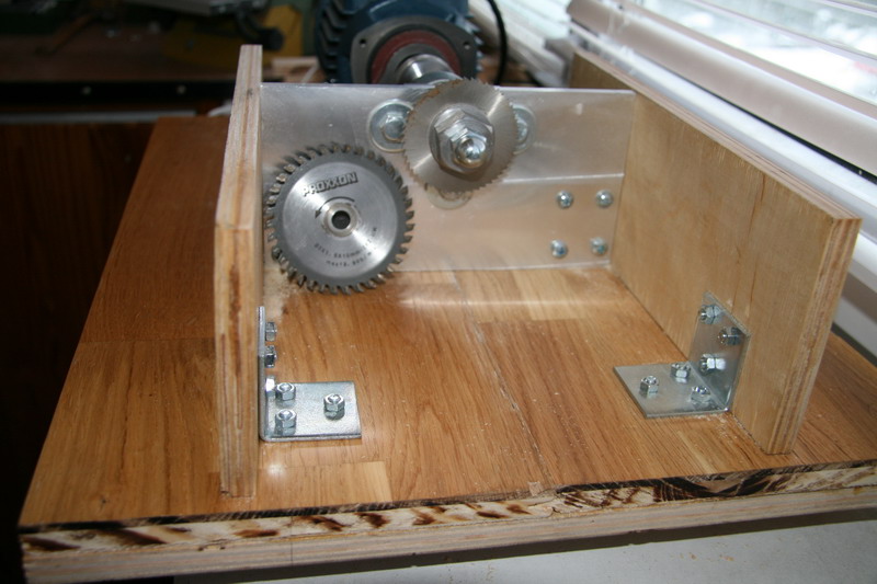
-
MONTANES by Garward - OcCre
Garward replied to Garward's topic in - Kit build logs for subjects built from 1751 - 1800
Continuation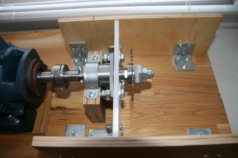
-
MONTANES by Garward - OcCre
Garward replied to Garward's topic in - Kit build logs for subjects built from 1751 - 1800
Continuation
-
MONTANES by Garward - OcCre
Garward replied to Garward's topic in - Kit build logs for subjects built from 1751 - 1800
Continuation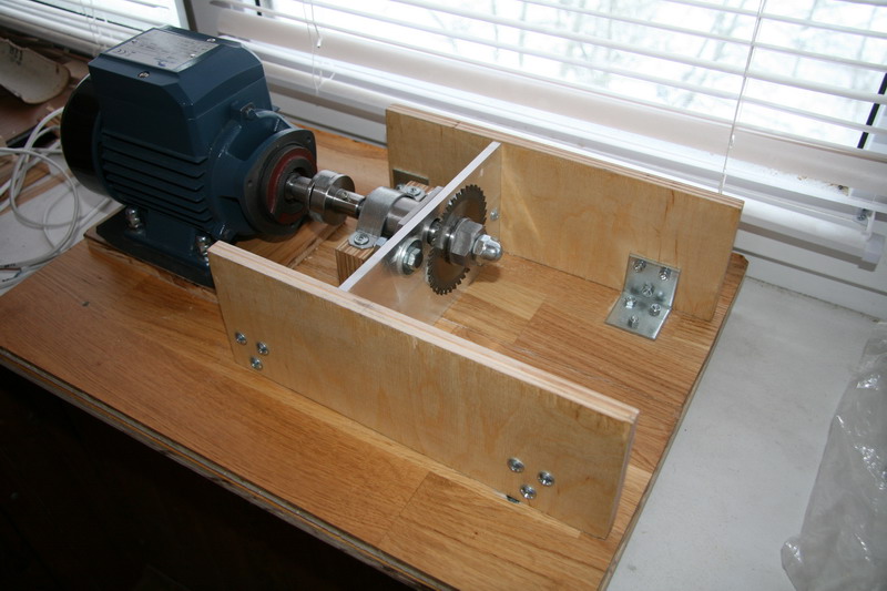
-
MONTANES by Garward - OcCre
Garward replied to Garward's topic in - Kit build logs for subjects built from 1751 - 1800
Continuation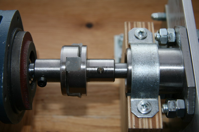
-
MONTANES by Garward - OcCre
Garward replied to Garward's topic in - Kit build logs for subjects built from 1751 - 1800
Continuation
-
MONTANES by Garward - OcCre
Garward replied to Garward's topic in - Kit build logs for subjects built from 1751 - 1800
Continuation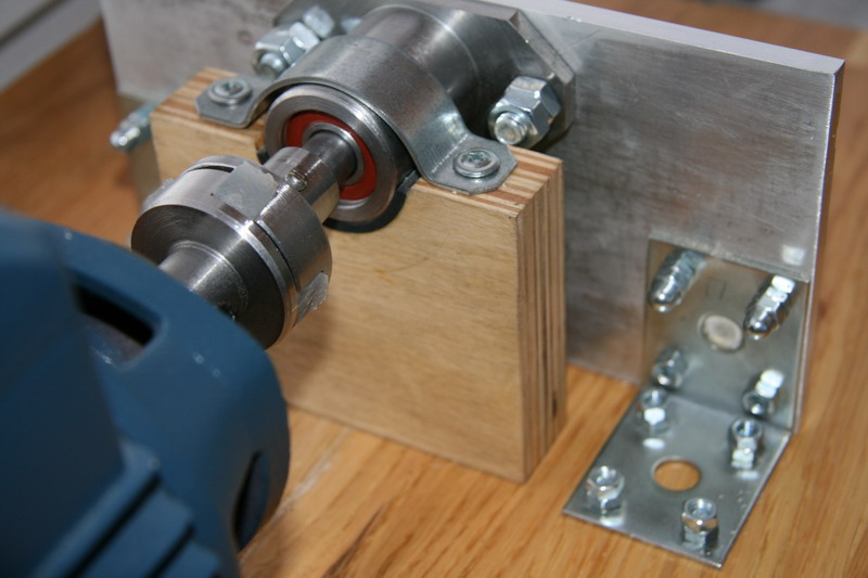
-
MONTANES by Garward - OcCre
Garward replied to Garward's topic in - Kit build logs for subjects built from 1751 - 1800
Material the knot of drive – steel ст 45, details of fastening of an emphasis to a table - duralumin Д16Т in the thickness of 15 mm, an emphasis (directing) section 16х20 mm from Д16Т, a carriage clamp - Д16Т, the screw in clamp М6 from ст 45, a clamp axis - a steel in diameter 6 mm. The engine costs on rubber linings in the initial thickness of 10 mm, rubber linings are established also on basis legs, their fastening to the basis and under bolts of fastening of the engine. On a photo 18 - 24 fastening the knot of drive to the engine and to the basis is shown. A rack of fastening of a flange (central) 200х105х8 mm from Д16Т, screws of fastening of flange М8, an intermediate rack - plywood of 24 mm (2х12 mm), lateral racks - plywood of 12 mm, fixing corners - a steel of 2 mm, screws M5.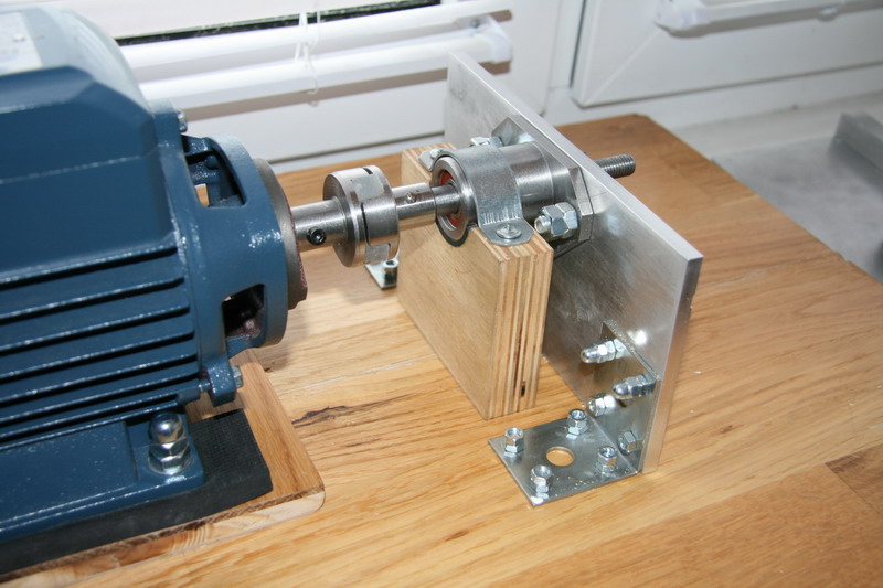
-
MONTANES by Garward - OcCre
Garward replied to Garward's topic in - Kit build logs for subjects built from 1751 - 1800
Continuation
-
MONTANES by Garward - OcCre
Garward replied to Garward's topic in - Kit build logs for subjects built from 1751 - 1800
Continuation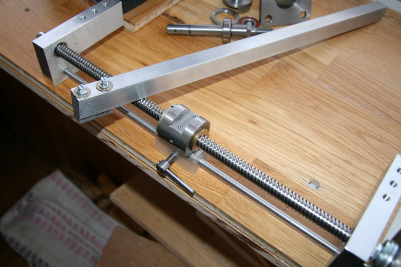
-
MONTANES by Garward - OcCre
Garward replied to Garward's topic in - Kit build logs for subjects built from 1751 - 1800
On a photo 15 – 17 the details of fastening to the table and moving of support are shown (sending). A screw is used by a diameter 12 mm with the special screw-thread, one turn of which is provided by the smooth moving of carriage with support on 12 mm along a table (screw ot a scanning device for the exact positioning of sensor on the surface of the controlled object at ultrasonic control).
-
MONTANES by Garward - OcCre
Garward replied to Garward's topic in - Kit build logs for subjects built from 1751 - 1800
Continuation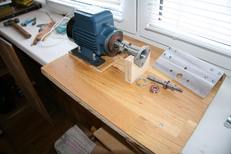
-
MONTANES by Garward - OcCre
Garward replied to Garward's topic in - Kit build logs for subjects built from 1751 - 1800
Continuation
-
MONTANES by Garward - OcCre
Garward replied to Garward's topic in - Kit build logs for subjects built from 1751 - 1800
Continuation