tkay11
-
Posts
1,829 -
Joined
-
Last visited
Content Type
Profiles
Forums
Gallery
Events
Everything posted by tkay11
-
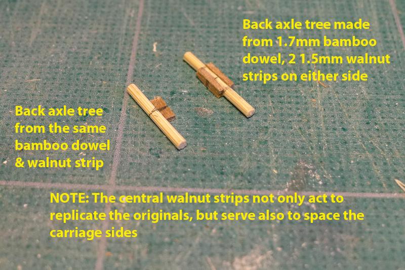
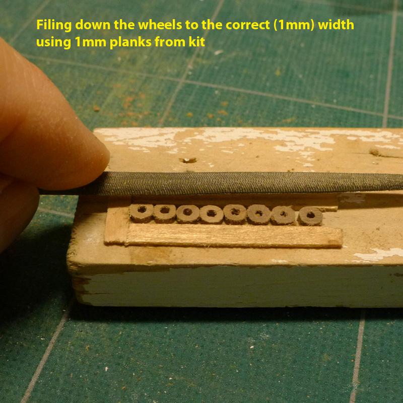
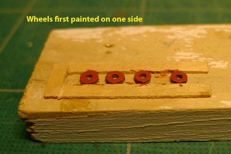
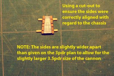
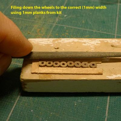
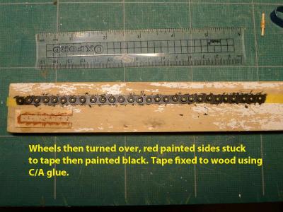
 The bases of the carriages were then simply made using 1.7mm bamboo dowel (that drawplate sure comes in handy) and walnut strips on either side to mimic the axle tree. The sides were then glued to the axle trees with PVA glue, and their alignment was made using a form cut from the plans and pasted to the cherry strip. The sides were 1mm further apart than dictated by the plan because of the over-size cannon I was using. The kit wheels were filed down to scale using a simple jig made of 1mm strips of lime that had been unused from the kit. Because of the variety of woods I had used in making the carriages, and because I knew I could not achieve the kind of beautiful finish others have achieved, I decided I had to paint them in red ochre. I had experimented with putting strips of black paper round the wheel rims to mimic the iron hoops that I have seen on other wheels, but in the end decided to paint the black on the rims. This I did by painting one side in ochre red, then, after it had dried, sticking the wheel face down to some Tamiya masking tape. I then painted the edges red to ensure that there was a seal to prevent any black paint escaping to the sides, and finished with two coats of black round the edges. Unfortunately, although the wheels are now the right kind of width, the finish is extremely rough. Next time I’ll try hard to make my own wheels. Tony

-
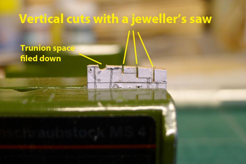
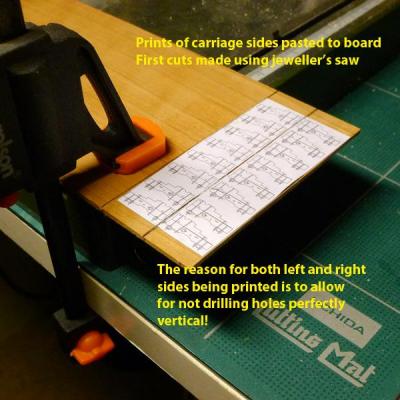
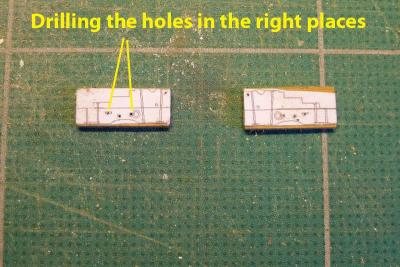
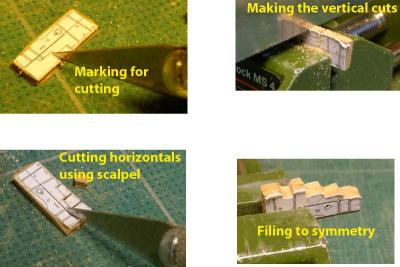
My dissatisfaction with the first attempt at gun carriages led to the 2nd where I tried to cut out the carriages from 1.6mm cherry wood board. I found I couldn’t manage to cut out the sides accurately so went back to thinking how I could do this. My answer was to scale the 4pdr carriage designs found in the AOTS book on the Alert down to 3pdr scale and then print out a sheet of them. To do this I used Photoshop rather than TurboCad as I found it faster. The printouts were pasted directly on to the cherry board, then cut them using a combination of jeweller’s saw and scalpel blade. Tony

-
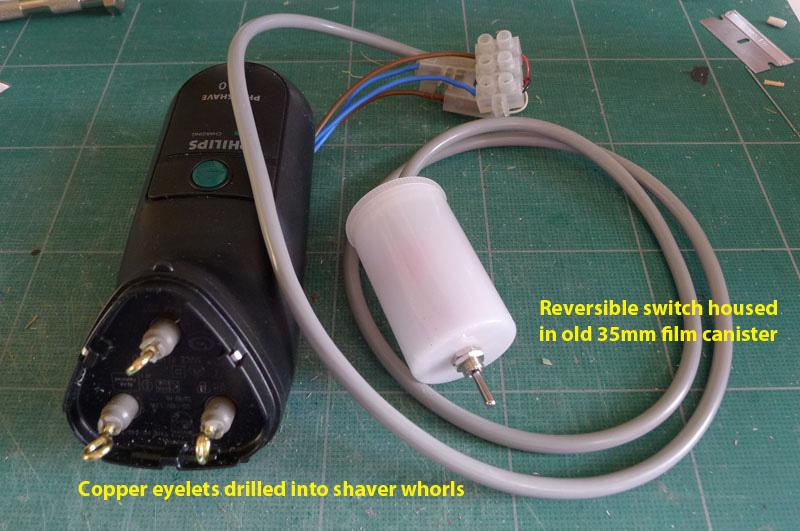
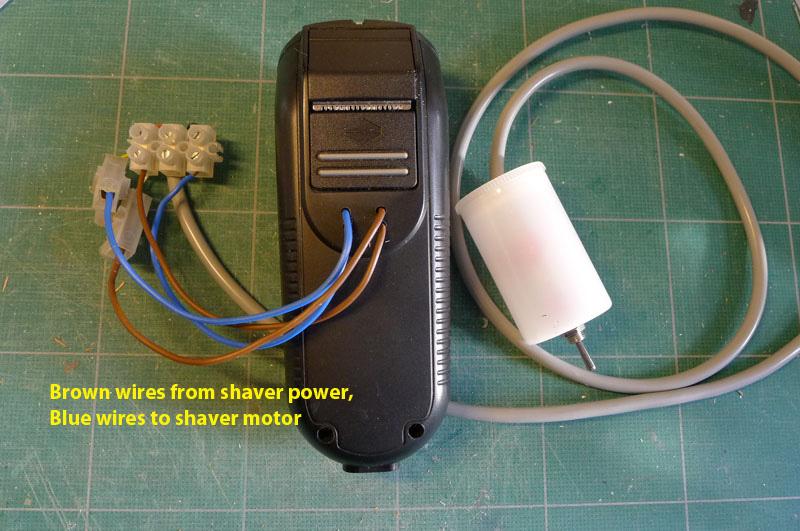
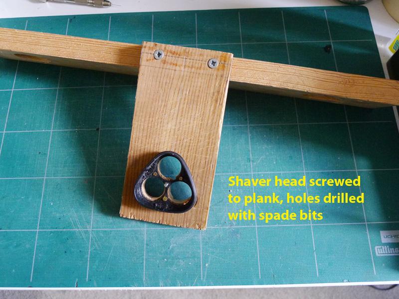
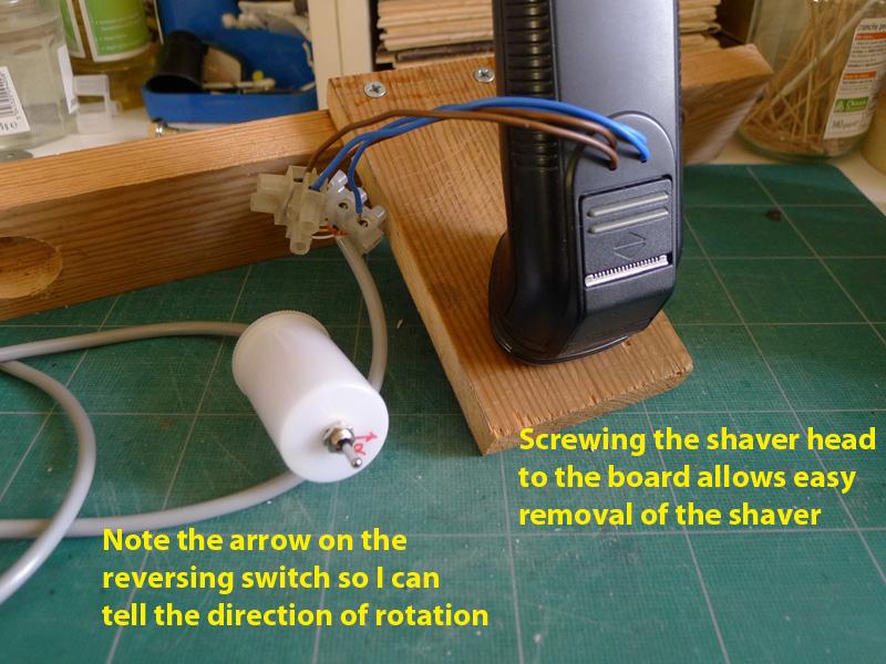
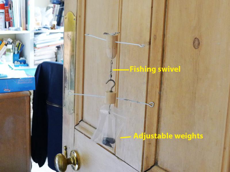
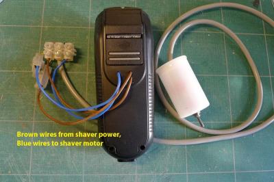
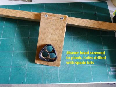
Whilst still thinking about the carriages, and being unsatisfied with the first attempt, I thought forward to the need for making breeching and other rope for the cannon as well as the anchors. So I decided to make a vertical ropewalk using the basic design shown in Ken’s (BRGreen) posting (which is now lost unless he re-posts it!). The only differences in my ropewalk were 1. using an old 35mm film canister to house the reversing switch; 2. keeping the old head of the shaver and screwing it direct to the faceplate so that it would be very easy to pull the shaver off the machine. 3. keeping the back of the shaver on and drilling holes for the wires from the power source and to the motor. I soon found out that the fishing swivel I was using was useless, so bought a ball-bearing swivel which improved rope-making considerably. I also found that the weight I had to use was far less than first expected. 10gm seemed to do the trick for the thread I was using. The breeching rope should be 4.25” circumference. This translates to 0.54mm diameter at scale. I achieved this using some old thread of my mothers. However, I have so far only been able to make left-handed thread from the right-handed thread that I have. I know I should be able to unwind the right-handed thread in order to make right-handed rope, but so far I have failed to manage it. Tony


- 269 replies
-
- 3
-

-
- Caldercraft
- First build
- (and 3 more)
-
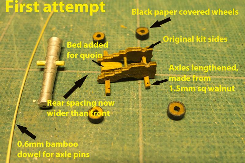
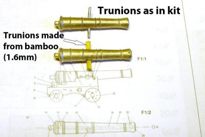
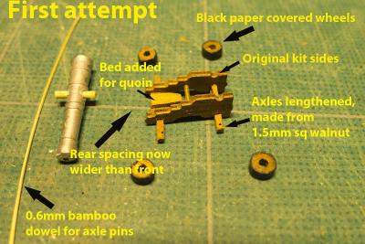
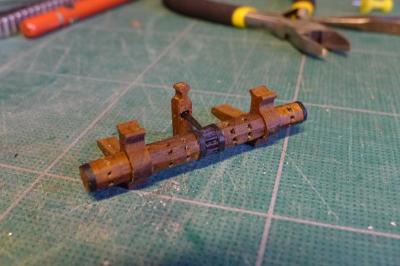
This part of the log was added on Jan 16 2013 === The 3pdr cannon were next on the list. Most of those who build the kit talk about how the kit cannon are oversize. Well, that’s true. Their length is 23.8mm (the equivalent of 5 foot, or a 3.5pdr)), whereas a 3pdr should be 4’6”. At scale 1:64 that would mean a length of 19.05mm. Seeing as I don’t have a lathe, I reckoned that I could live with the 3.8mm difference and use the kit cannon. The only thing I didn’t really like about the cannon was the trunions. They just looked like very thin pins. So I decided to drill out the old trunions and replace them with 1.6mm bamboo dowel I made from barbeque sticks using a drawplate. However, when I started work on the carriages I didn’t like them at all. The carriage sides were parallel (not following the lines of the cannon), the axle trees had square axles, the wheels were so thick they made the carriages look like go-karts or quad bikes, and the carriages themselves were too long. I therefore decided to embark on the rather foolish notion of building the carriages myself – especially after seeing the work of others on this forum (e.g. Dirk’s/Dubz and Daniel’s/Siegfried). The reason it was foolish is that, as you will see, the finish I achieved was not very good. All the same, the experience was worth it as I think I’ll be able to do much better in the future. I decided to make carriages that at scale would be 3pdr, whilst continuing with the 3.5pdr cannon of the kit. I could have made the carriages equivalent to 3.5pdr, but my whole thinking was dogged by the well-known problem of the kit: notably that the aft two gunports are so low that the cannon only fit with difficulty. I therefore had to make a carriage that would allow the cannon to go through these aft gunports with ease. I still don’t know how others achieve this trick! Below you’ll see the pictures of my first attempt. In this I used the original kit carriage sides, but replaced the axle trees with longer axles made from 1.5mm sq strips from the kit, a roughly fashioned bed for the quoin, and paper covering the wheels to look like the iron hoops. Tony
-
Now, as far as the windlass is concerned (and I can’t really determine whether my windlass is concerned at all), I coated the pawl bitt and windlass with refined linseed oil (as suggested by Daniel/Siegfried) and stood them together to see if they would like each other. I think they do. That was all a very interesting set of learning experiences! Tony
- 269 replies
-
- 1
-
-
- Caldercraft
- First build
- (and 3 more)
-
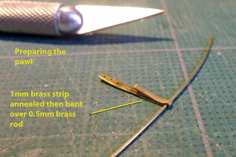
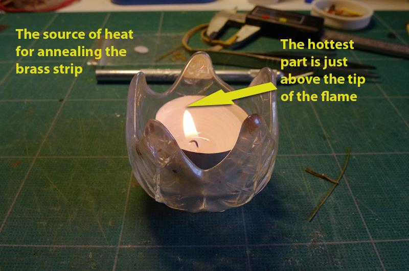
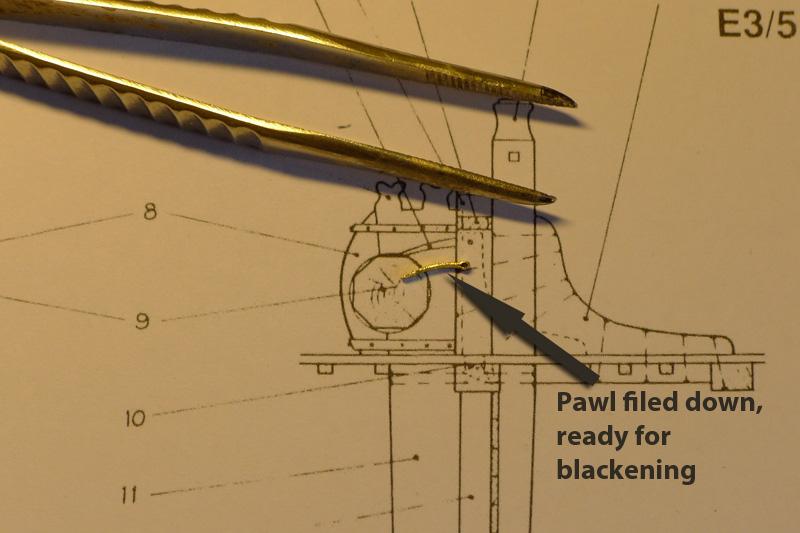
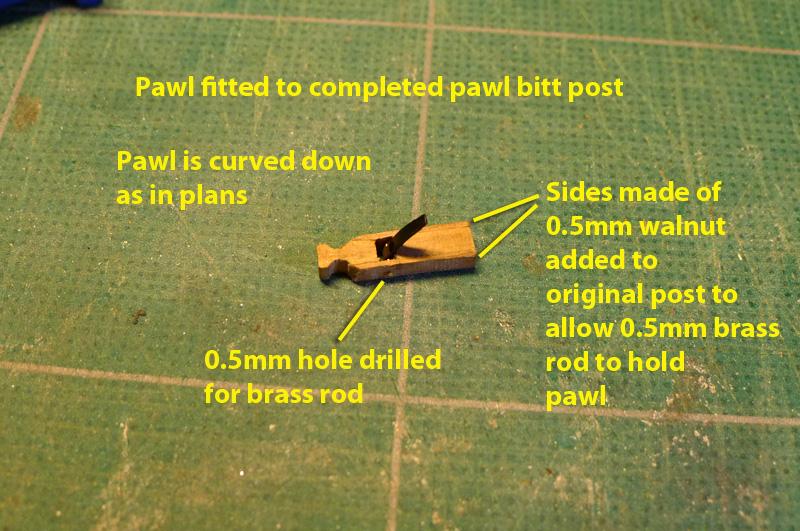
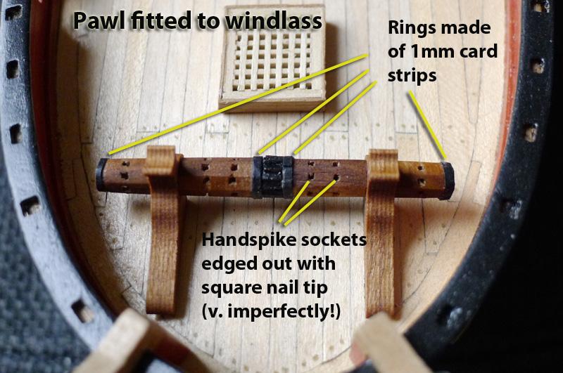
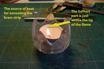
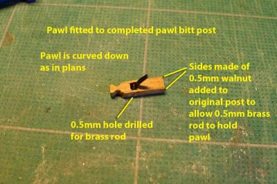
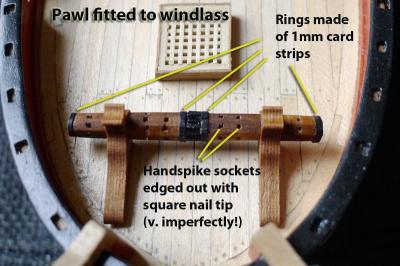
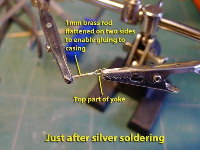
Finally, for this stage of my work, I came to the pawl bitt post. The kit suggested just sticking a strip of 1mm thick walnut into the post for the pawl itself, but this didn’t look at all right when looking at what a pawl should be doing. So I decided to fashion the pawl out of copper sheet, and lengthen the post by 1mm so that it could take the pawl on a 0.5mm brass wire. I made the pawl by annealing a 1mm strip of brass, bending it over the brass wire that I intended to use as its rod, cutting to the right length (0.7mm), and sealing the folded edges by soldering with silver flux. I then filed the brass down to the shape shown on the ‘Alert’ plans, and bent it to a gentle curve. I found that annealing doesn’t seem to require red heat. I just held the strip over the tip of a candle flame and that seemed to do the trick quite well. After cutting the pawl bitt post, I glued two sides of 0.5mm walnut to the post, leaving a gap between the two bits of the post, drilled a 0.5mm hole for the wire, and inserted the pawl. Tony


- 269 replies
-
- 1
-
-
- Caldercraft
- First build
- (and 3 more)
-
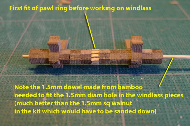
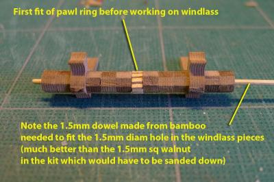
The three rings compared, and initial assembly with windlass. One of the things I found slightly irritating was that they suggested that a strip of 1.5mm sq walnut be used to hold the pieces of the windlass together. Now 1.5mm square means that the diagonal is more than 1.5mm whilst the holes in the windlass pieces were exactly 1.5mm. This would mean I’d either have to sand the supplied strip down to achieve the diameter of 1.5mm or else make a dowel from bamboo. So out with the bamboo barbecue skewers and the drawplate and make a dowel I did – reckoning my sanding skills with fragile walnut were not likely to be good enough. Tony

-
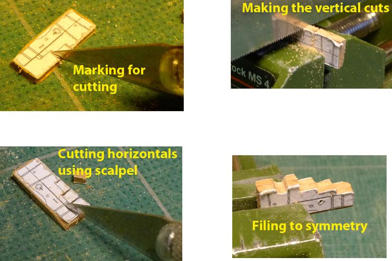
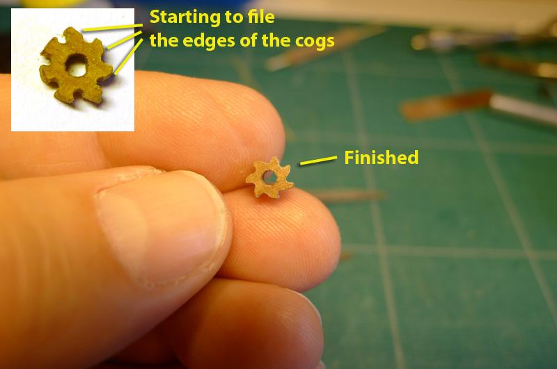
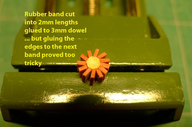
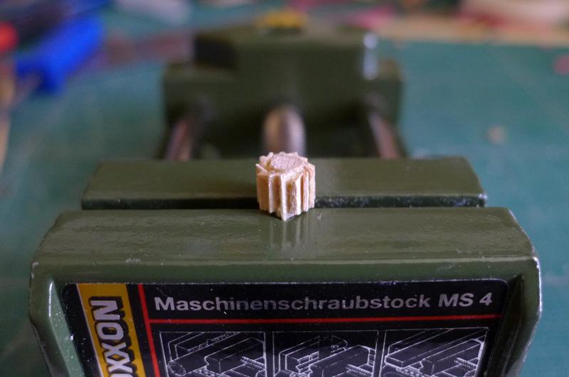
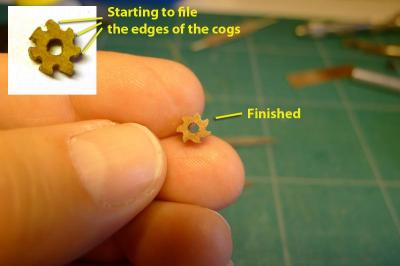
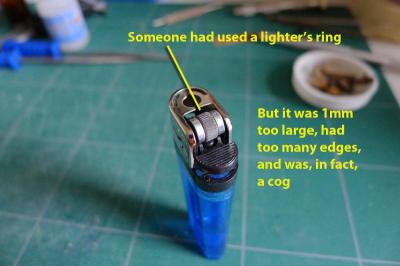
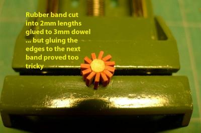
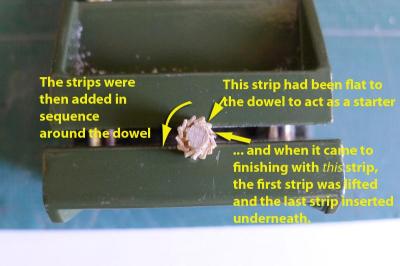
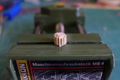
Now we get to the pawl ring for the windlass. This caused me no end of hilarity. The ring supplied with the kit is a cog, and I wanted it to look like a pawl ring. So my first attempt was to use the black card supplied with the kit, cut into 2mm strips and glued to a 3mm dowel. However, I gave up when I couldn’t get the complete ring to look balanced, and there was the additional difficulty of the card being too thin to look like the edges on a pawl ring. (I don’t know how Daniel/Siegfried did it, but his work with the card looks entirely magnificent). I even tried a plastic ice cream carton that had the right thickness (0.8mm) but the plastic didn’t hold to any of the glues. So I gave up with the card and thought to file the cog down so that it looked like a pawl ring. Unfortunately, whilst it was clearly a pawl ring, it had far too few edges (7) whereas the plans for the ‘Alert’ showed a pawl ring with about 14 edges. So I tried a lighter’s ring, as someone had done on another model, but it was 1mm too large in diameter, had too many edges, and was, in fact, a cog wheel. Then I tried cutting a rubber band into 2mm strips and gluing the edges to a 3mm dowel. But when it came to gluing each edge to the next to make a pawl ring it proved to be too difficult – the edges were so elastic that it was very hard to align them and keep the edges straight. Besides, it was again too large for the windlass. Finally, I thought I’d get back to the idea that Daniel/Siegfried had had at first: use wood. So I cut 2mm strips of lime and glued them to the edge of the same old 3mm dowel. But this time, I found the trick! Start with one of the strips glued flat to the dowel and use that as the edge to stagger the remaining strips one by one. By using PVA glue, which doesn’t set too quickly, by the time I completed the ring I could lift up the first, flat strip and insert the last remaining strip under it. That just left me to cut the whole pawl ring to size (3mm wide), file the edges and paint it black. HOORAY! I got there in the end! Well, at least for my level of expertise! Tony
-
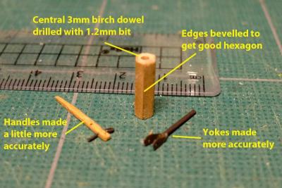
This part of the log was added on Oct 23 2012 === Re-doing the pumps. Well, the desire to do better overcame me, and I did the pumps again – this time in cherry. I’m glad I did it because I was able to correct what I didn’t like in the previous pump set: I bevelled the edges of the cherry strips, used a 3mm birch dowel as the centre on to which to glue the strips (and drilled out a 1.2mm hole to take the spears), made narrower metal bands, made the pump handles a little more accurately, painted the discharge ports black, used refined linseed oil rather than varnish Tony

- 269 replies
-
- 2
-
-
- Caldercraft
- First build
- (and 3 more)
-
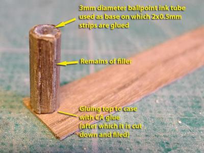
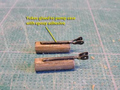
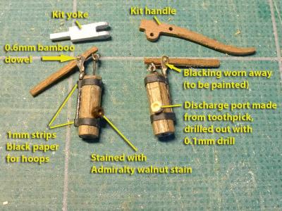
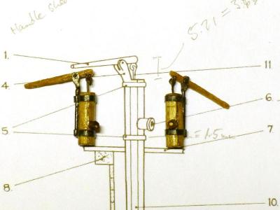
Now the pump casing. I took some 0.5x2mm walnut strips and glued them around a 3mm diameter plastic tube I took from an old ball-point pen. I used CA glue which does not really stick well to the tube, but it does to the wood edges. The top of the casing was made from 0.5mm walnut strip as shown in the picture. The yokes were then glued to the casing using rapid epoxy adhesive, the hoops were made from 1mm strips of the black paper supplied with the kit. The discharge ports were made from 2mm diameter tooth picks nicked from the kitchen table, and partly hollowed out with a 1mm drill bit. The ports were then stained using Admiralty water-based walnut stain. The handles were cut from 1mm walnut strips, drilled with a 0.6mm bit. The spears were made from 0.5mm brass rod, and the eyes for the spears similarly. The eyes were glued to the handles using epoxy adhesive. The pumps were then assembled by sticking 0.6mm bamboo dowels through the yokes (luckily I had some dowels left over after making them for treenails). Finally I gave a coat of silk varnish – which reflects the light in the photo. After all that, my fear of undertaking what I thought would be unachievable has diminished. The finish is not up to the standards of others, but the learning path is well under way. Tony
- 269 replies
-
- 2
-
-
- Caldercraft
- First build
- (and 3 more)
-
Thanks John (Jim Lad)! It's great to be back. As others have mentioned, it really is like a rejuvenation to have everyone putting as much as they can back into this site. I've now nearly restored my log. Just a few more episodes and then I'm up to date! Tony
-
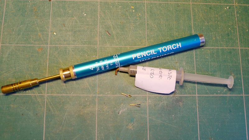
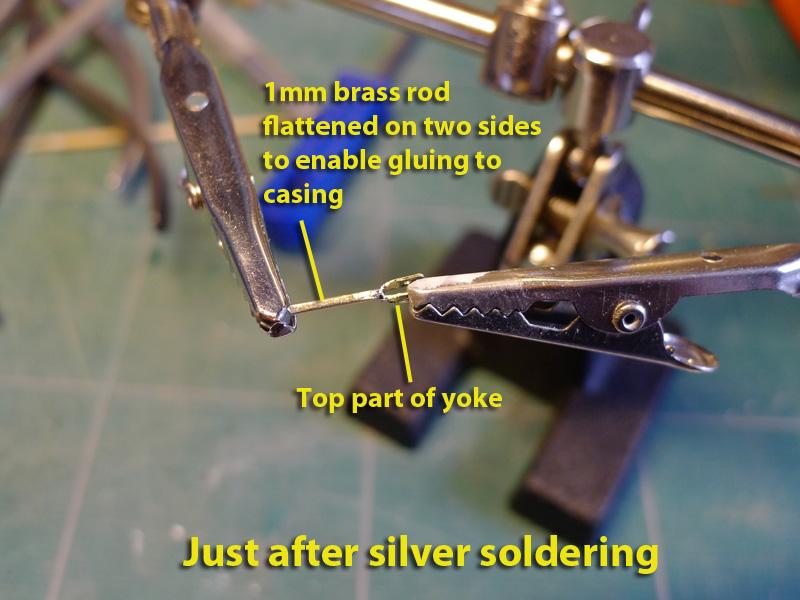
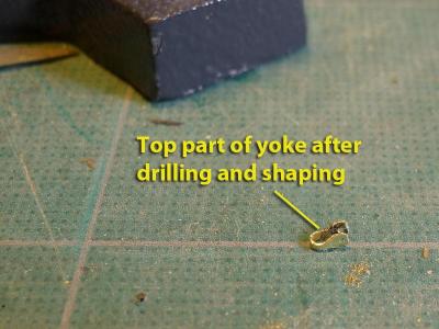
The pumps. This was a lovely challenge, as the kit pumps looked rather over-size and clunky. So back to the plans of the ‘Alert’ again. But how to make the yoke? I decided to make it out of brass, and to hold it with a brass rod. So I cut a length of 2x0.5mm from a brass plate, drilled 0.6mm holes 7mm apart and filed down the central section to fit on to the 1mm brass rod. Then I took the plunge and learnt about silver soldering (after studying the article by Russell Barnes in the Model Shipwright’s Database on this forum). What a nice skill to learn! I used a pencil torch that cost about £4 from the local DIY store, and some 62/2/36 Soft Solder Silver Paste in a 25gm syringe (£9). The only thing that surprised me was the need to refill the torch with gas lighter fuel very frequently. Tony


-
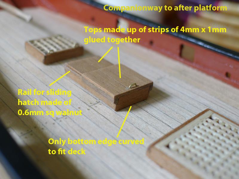
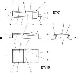
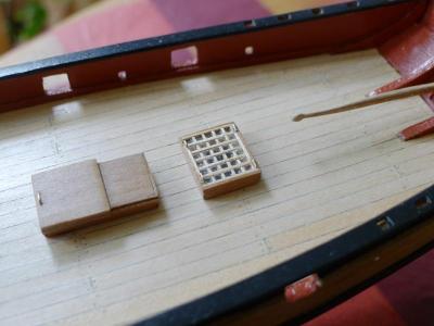
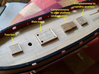
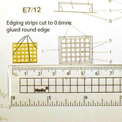
The last hatch to consider was the companionway to the after platform. This is shown in the ‘Alert’ plans as a sliding hatch. I posed a question about this in the forum (see http://www.modelshipworld.com/phpBB2/viewtopic.php?t=21153&highlight=). My problem was how to make the roof look like a single pane as shown in the plans. I had thought this was either one block of wood, or even possible made of lead in the original. In the end, since nobody came up with an answer, I went ahead and made the roofs by butting 1x4mm planks together and then sanding fairly vigourously. I made the rail for the sliding panel from a 0.6mm sq strip using the jig I had used for the mullions in the previous postings. This was topped off with a handle made from 0.5mm brass wire. It will be noticed by many that neither the captain’s hatch cover nor the roofs for the companionway to the after platform were curved to match the deck’s curve. I only did this for the fore and main hatches, and, of course curved the bases of all the hatches to fit closely to the deck. None of the hatches are yet glued to the deck. This will allow me to make any small adjustments in relation to the needs of other deck fittings such as the pumps. Tony

- 269 replies
-
- 1
-
-
- Caldercraft
- First build
- (and 3 more)
-
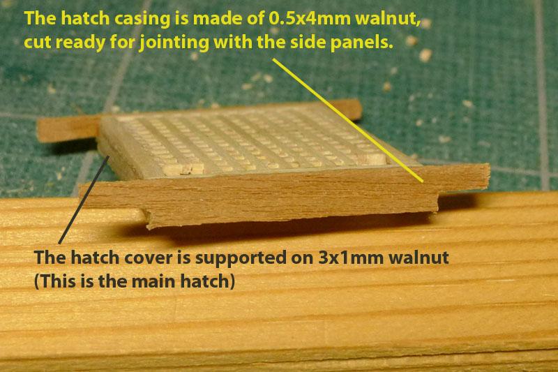
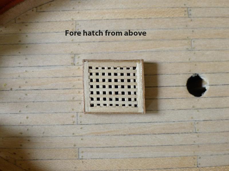
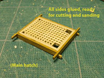
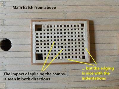
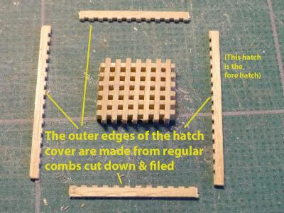
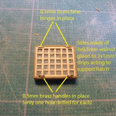
The cover was then placed on a form made of 3x0.5mm walnut, and the whole assembly sided by 4x0.5mm walnut as shown in the photo. To allow for the jointing at the ends, the side pieces were cut over-size then jointed, then cut down as shown in the photos. This was not entirely successful from the hatch’s point of view, since you can still see lines where the combs are spliced. However from my own point of view I have enjoyed the effect achieved with the edging strip. The same procedure was followed for the fore hatch, except that in this case the combs were not spliced and a narrower gap used to separate hatch cover from edging strip. Tony

- 269 replies
-
- 1
-
-
- Caldercraft
- First build
- (and 3 more)
-
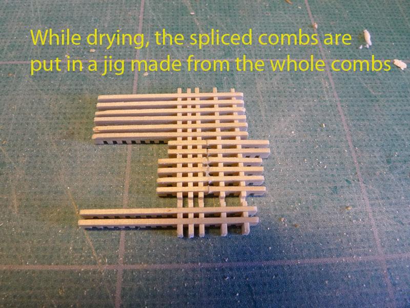
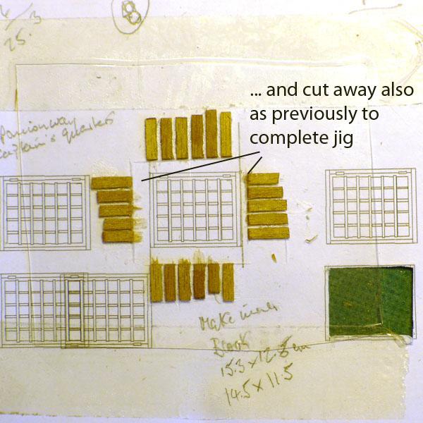
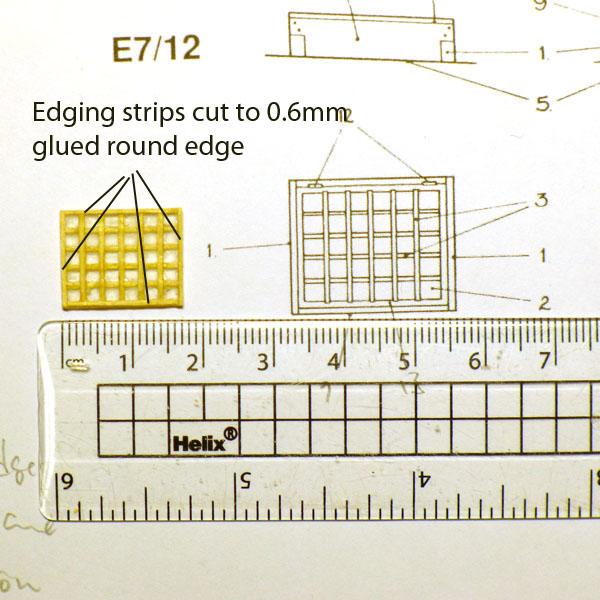
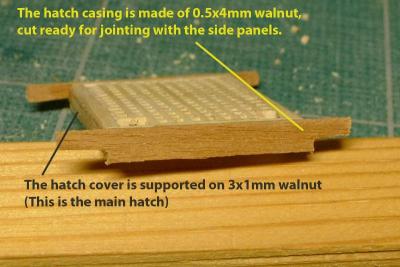
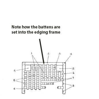
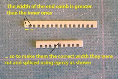
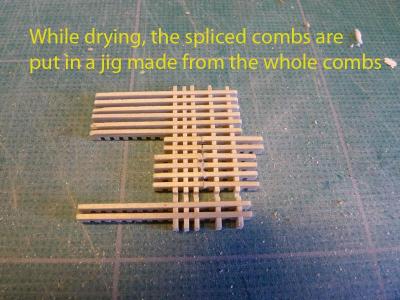
Next up was the main hatchway. The plans for the ‘Alert’ indicated an edging strip into which the combs were inset. The question was how to achieve a constant width edging strip with such indentations. The most obvious way of making the edging strip seemed to be to lay the supplied cones on their side and place those against the hatch. This would entail cutting down the teeth to provide enough of a gap with the hatch cover. One of the interesting factors was that the ends of the combs supplied in the kit had teeth that were slightly wider than the inner teeth. This meant that at each end of the hatch they would provide a bit of extra distance against which to place indentations. However, the hatches were going to have to be shorter than the combs provided. So the main hatch was made by cutting them in the middle to the appropriate length and then splicing the remaining ends using epoxy adhesive as shown in the photo. The pieces were left to dry in a jig made from the full length combs from the kit. Tony
- 269 replies
-
- 1
-
-
- Caldercraft
- First build
- (and 3 more)
-
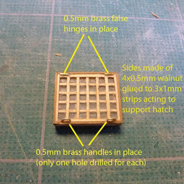
The edging strips were then added to the glass cover. Hinges and handles were added using 0.5mm brass wire, which I left un-blackened. This is seen in the following photo. Tony
- 269 replies
-
- 1
-
-
- Caldercraft
- First build
- (and 3 more)
-
This next lot of photos shows the final steps in the making of the companionway cover. Tony
- 269 replies
-
- 2
-
-
- Caldercraft
- First build
- (and 3 more)
-
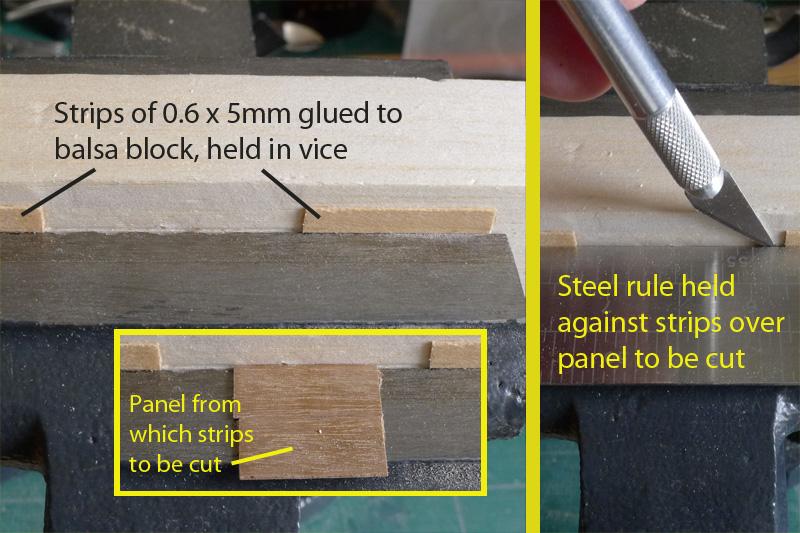
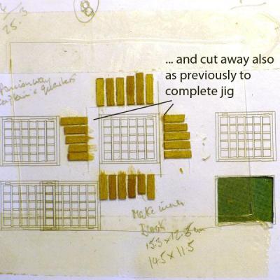
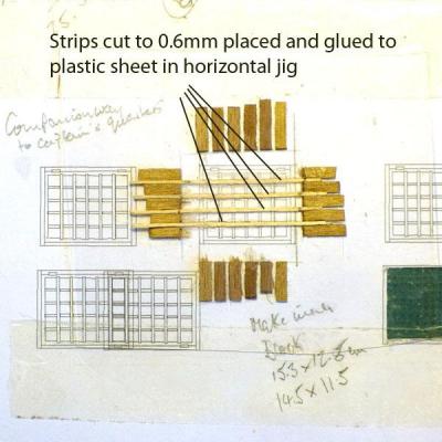
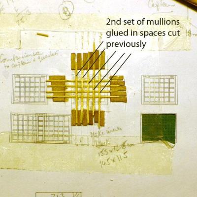
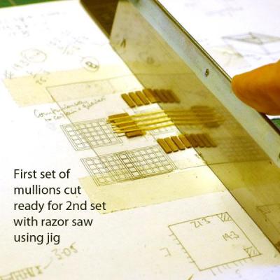
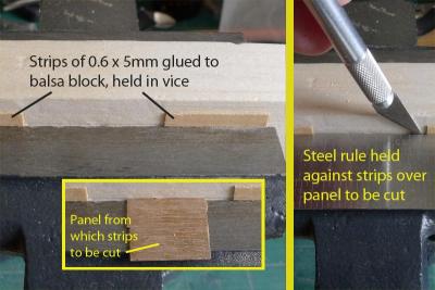
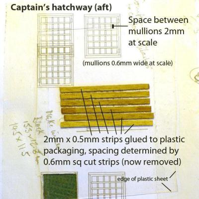
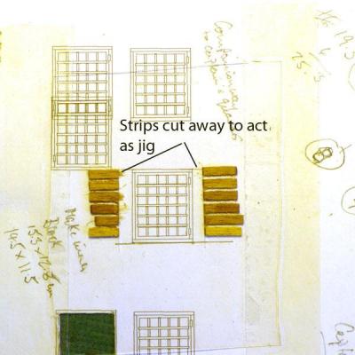
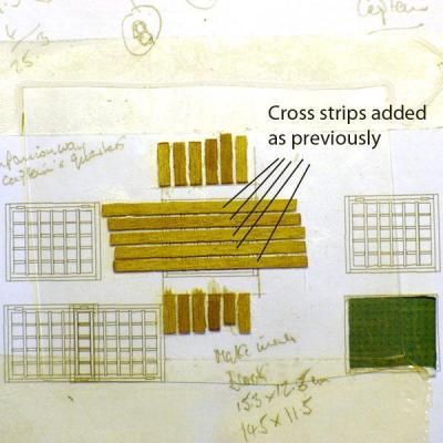
This section of the log was first added on Sep 30 2012 === I spent quite a bit of time figuring out how to do the hatches and companionways. The kit plans seemed a little boring as they would all look identical, so I turned to the ‘Anatomy of the Ship’ book of the cutter Alert. There each hatch is different, and poses problems of its own for construction. First off was the aft-most (captain’s) companionway. This, in the plan, has glass placed in mullions on a vertically opening hatch. So I tried to find out how to make glass panes that might look somewhat realistic. As is so often Hubert (‘Bosco’ on this forum) came up with a nice idea for making a jig (I'll have to research this link again, but you'll also find it on his site 'Wooden Ship Modelling for Dummies'). As a result I made the window using some thermoformed packing material, and by cutting strips of wood 0.6mm sq using the jig shown in the photo. Tony

-
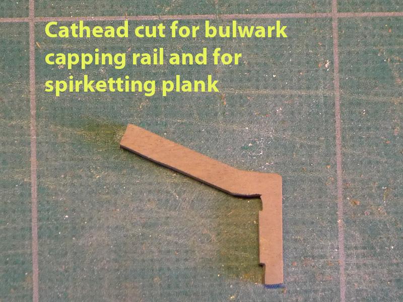
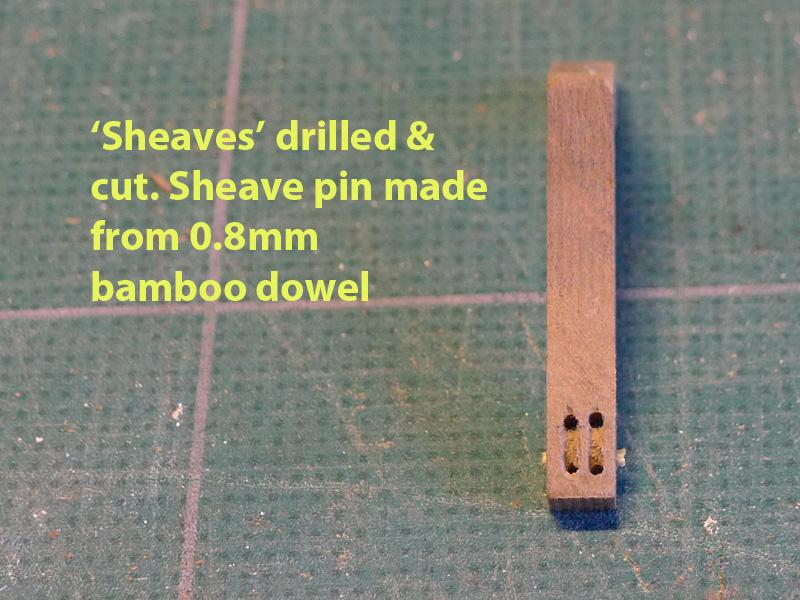
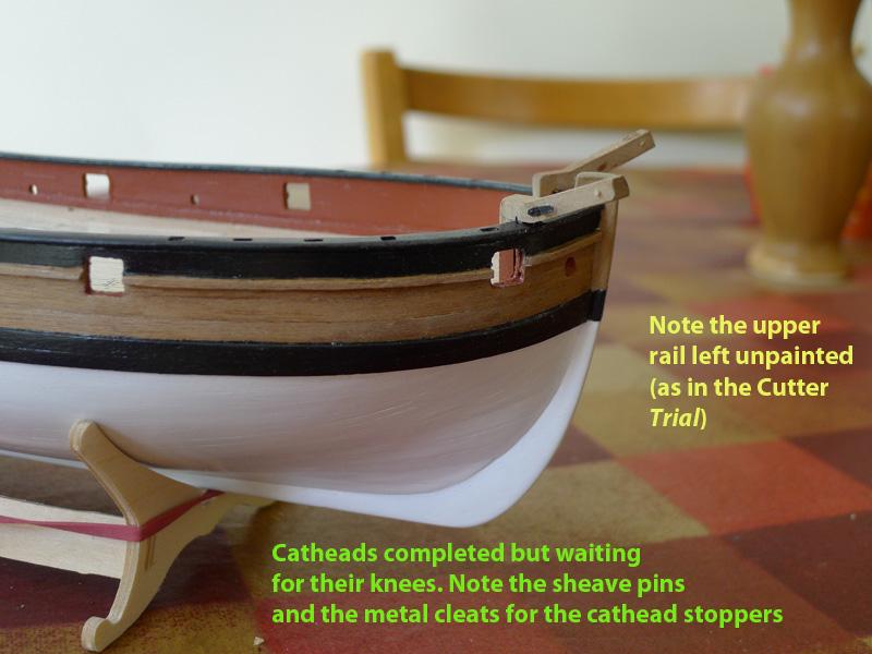
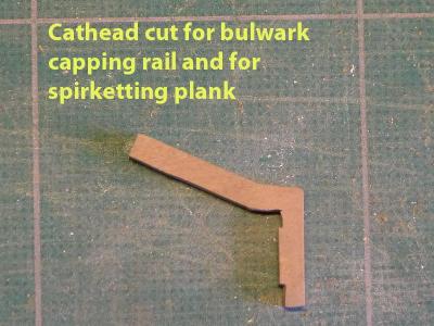
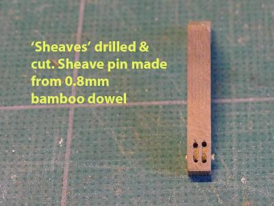
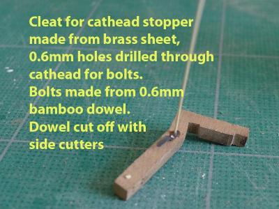
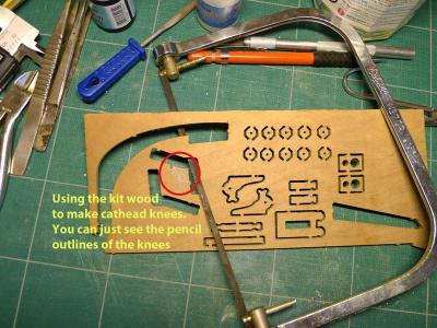
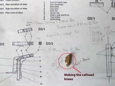
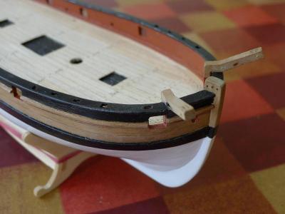
It’s now the time to do some of the deck fittings. First of these are the catheads. One thing I thought I couldn’t handle at my level of skill was the reproduction of the carving on the cathead end. One day, maybe, but simpler things first. The catheads themselves had to be cut to allow for the bulwark capping rail and the spirketting planking on the inside of the bulwarks. This brings up one question I should have asked earlier: would the catheads and their knees have been cut into the capping rail rather than be cut? I would have thought that cutting into the capping rail would have made more sense from the point of view of strength. Any views anyone? I spent some time thinking about how to replicate the sheaves. In the end I opted for drilling 0.8mm holes for each of the ends of the sheaves, then connecting the edges of the holes by straight lines cut with a scalpel, and digging away the wood between the holes to just below the surface. I also used the drill bit to angle the edges inside the ‘sheaves’ to give more of a circular appearance. I then drilled a hole at right angles to this to represent the sheave pin, and inserted a 0.8mm dowel made from bamboo (yes, I finally bought a drawplate as I found one for £3.50 made from Indian steel, and a pack of 100 bamboo barbecue sticks for £1). I made the iron cleats for the cathead stoppers from brass sheet as per the plans for the Cutter Alert. These had 0.6mm holes drilled and I also drilled holes right through the cathead so that the dowels could be seen on the other side as well. The cleats were blackened with brass blackener. As an aside, I found that the slight patchiness arising from imperfect use of the blackener was simply remedied by a touch of black paint. In this way I touched up the pintles and gudgeons as well. I am now making the knees for the catheads. Again I used the wood for the catheads from the kit. The advantage here was that the angle for abutting the lower part of the cathead was correct, so all I had to do was cut out a rough area, then cut into one side to allow for the capping rail and the upper rail, then file the outer edge to shape. Tony
-
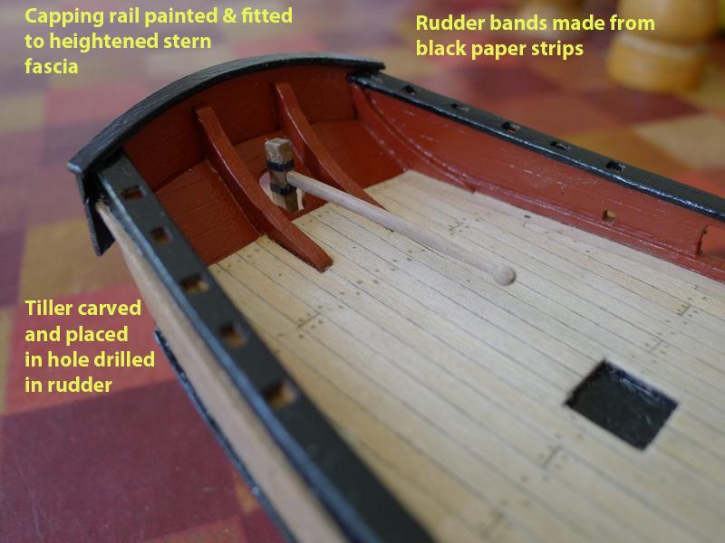
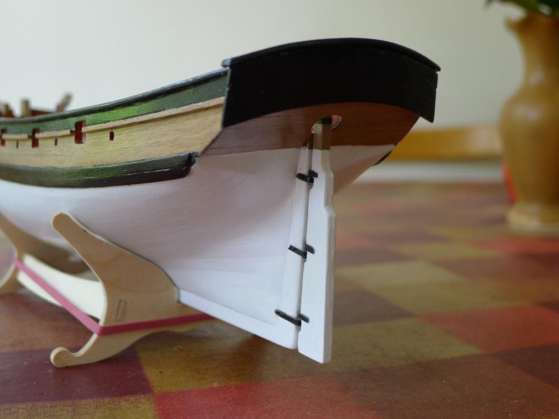
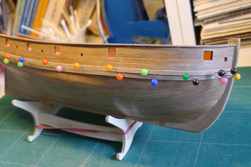
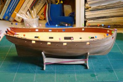
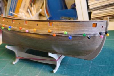
Painting was now a consideration. Against my wife’s wishes, I decided to paint the hull. She liked the wood so much and the detail of the planking, but my argument was that I wanted to have experience of the different aspects of model building. Initially I thought I’d paint to the waterline, but after some discussion and research, I decided to paint to the wale following the example of models in the National Maritime Museum, several paintings pointed out to me by other members of the forum, and two notable builds of the Sherbourne in this forum (Siegfried and Daniel). Also I decided against trying to be authentic as to colour or weathering. I just used plain white. Also, following the example of the Cutter Trial of 1790 at the NMM, I painted the bulwark capping rails and planks beneath them black, but left the upper rail unpainted. The stern fascia and its capping rail are painted black while the inner part of the fascia is red ochre. Finally, I decided not to have the hull ultra-smooth as I wanted to see the edges of the planks as much as possible. Tony


- 269 replies
-
- 1
-
-
- Caldercraft
- First build
- (and 3 more)
-
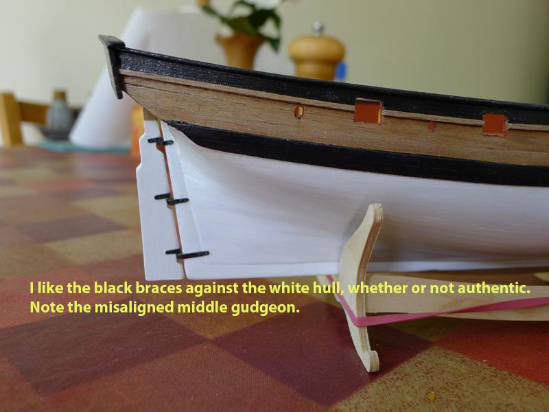
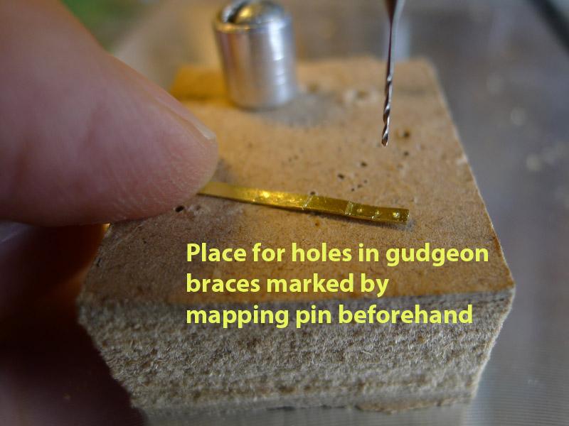
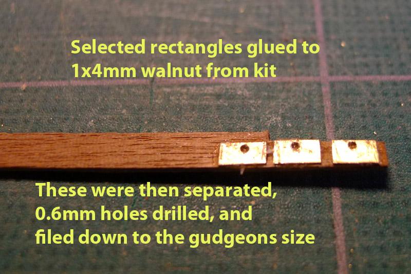
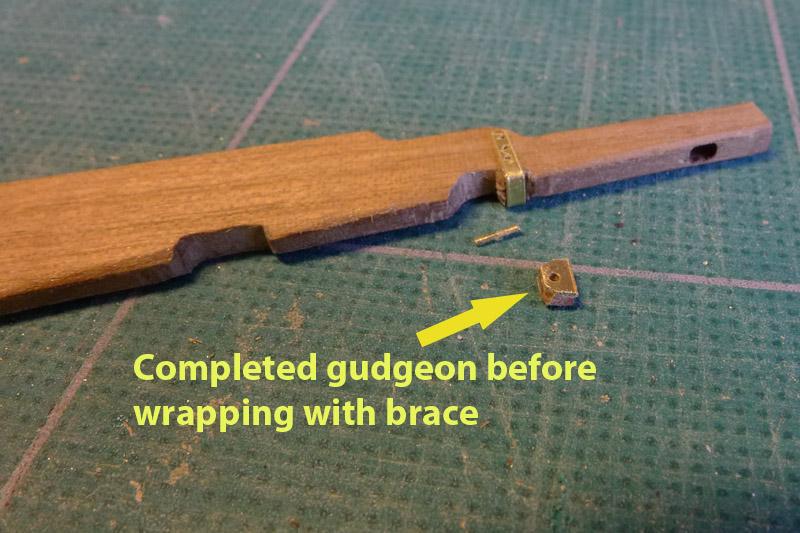
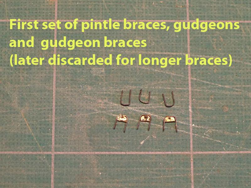
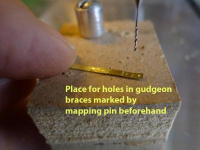
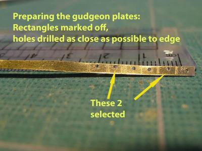
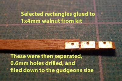
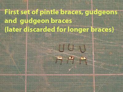
Now the gudgeons. My attempts at cutting out of wood showed how fragile the walnut is at that size as the pieces just disintegrated. So I made the gudgeons by gluing brass plate to the top of 1mm walnut strip then cutting out. The assembly was then glued with epoxy adhesive to the braces. You’ll see from the photos that I had to experiment with the drilling to get the holes as near to the edge as possible. It was only after doing all this that someone on the forum told me I could have done the gudgeons with brass tube – something that seems blindingly obvious and clearly something I must have missed in studying other people’s logs. Still, at least I knew the 0.6mm holes I had drilled in the brass plate would provide a reasonably tight fit for the pintles made from 0.5mm brass rod. Unfortunately, after all that effort, I still failed to obtain a narrow enough gap between rudder and stern post, and the middle combination of gudgeon/pintle was not perfectly aligned. The reason for this was simple. I first had thought that I would have to glue the braces of the gudgeons to the stern post. This would have to be done to a painted hull, and my first attempt using rapid epoxy adhesive on all the gudgeon braces at once resulted in lots of slippage. I then had to remove the gudgeons with their braces and start again. I picked up an idea from Dan Vad and decided I’d fix them with bamboo dowels. Seeing as I now had a nice stock of 0.6mm and 0.8mm dowels made with my new drawplate, I gave it a go. I also discovered that the easy way of aligning it all was to put the bottom set of gudgeons/braces in first. That way the rudder could rest on the bottom set whilst aligning the remainder of the gudgeons. So the problem of gluing to paint never arose – I simply fitted the braces using dowel covered in PVA glue. It seems very strong. But I still had that middle gudgeon out for some reason. I think it must have been my eyesight at the time. Tony

-
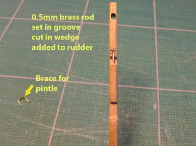
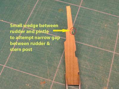
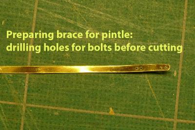
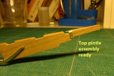
Now the rudder. My, what a lot of grief this caused me. I started with the tiller. Like many others, the design of the kit tiller seemed wrong in terms of its attachment to the rudder. So I cut a strip of wood from the kit and shaped it roughly according to the design for the Cutter Alert. I then drilled a hole through the tiller and squared it off with a needle file. To mimic the metal plates on the rudder above and below the tiller, I cut strips from the black paper supplied with the kit and glued them to the rudder using PVA. No real problems there, and a pleasure to find I can do this kind of thing. You’ll see the picture of the tiller in a subsequent post on the painting. I studied the plans for the Cutter alert for some time and saw how the pintles and gudgeons were made. I was mightily impressed by how narrow the gap was between stern post and rudder, and thought that I’d have a go at achieving such a narrow gap. I also studied the ways that other modellers have made the pintles and gudgeons, and as I didn’t have solder and couldn’t see my way to having the skill to bend brass plate so accurately, I set out on the idea of making the pintles by putting a wood spacer on the rudder, cutting a groove, gluing in a 0.5mm brass road with epoxy adhesive (CA glue didn’t seem to hold it well), then holding the whole assembly with a brass brace. The gudgeons I thought I could make from wood, then wrapping the braces round them. The brass was blackened after cutting. Pintles first. I cut the 0.01” brass plate into strips by scribing the plate with a scalpel, cutting with some kitchen shears, then filing down to the exact width. I drilled the 0.6mm holes for the brace bolts with a drill press and Proxxon drill (the only power tool I have at the moment). Tony

- 269 replies
-
- 1
-
-
- Caldercraft
- First build
- (and 3 more)
-
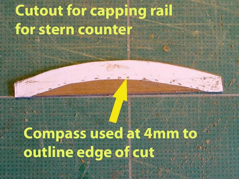
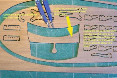
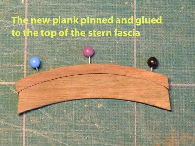
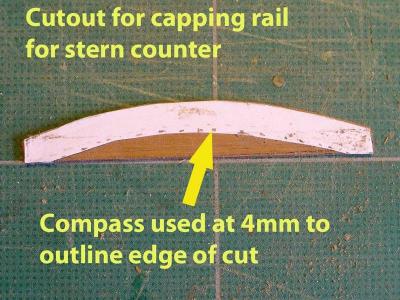
The next issue was the stern fascia. Many builders have noticed how it seems too low, and there have been many ways of approaching it. I decided I’d raise it by an extra plank, then cover the whole fascia with a capping rail. First was to cut a piece of the same thickness from the board that held the stern fascia. Apart from the fact that the board was handy, it also allowed me to have an accurate curve for the extra piece, as can be seen in the photos. You’ll also note that I used dividers to scribe the edges of false planks in the stern fascia so that the top new piece looked more natural (well, to make the whole fascia look more natural as it was made of planks). I scribed the backs of the fascia as well as the stern counter as well. To make the stern capping rail, I rolled a piece of paper across the top of the fascia so I could get the curve right, then with a compass measured a 4mm width (as you will see in the photo), then cut the rail out, soaked it and bent it to the top of the fascia. You’ll see the finished rail later on when I discuss the painting. I had to glue it with CA glue, though. Tony

-
This part of the log was initially added on June 21st 2012 === During the last month I’ve been learning on a number of levels. First off was TurboCAD which I decided to learn in order to be able to re-scale and create plans from which I could draw various components – as well as to prepare for general modelling from plans in the future. Then I spent some time learning about anchors, catheads and rudders. Then I tried various ways of making the rudder pintles, gudgeons and braces. Finally I decided on whether and how to paint the hull. Learning about TurboCAD was a revelation, as suddenly I understood why so many of the modellers on this forum use a CAD programme. I could instead have used Photoshop to resize plans and work with layers (as I am very comfortable with that software), but CAD seems to do this in an easier way, and is more flexible in analysis of measurement. So, back to the Sherbourne. First off was putting on the bulward capping rails, the upper rails, and main wales. I discovered the reason why the kit main wale was to be put on in two 3mm strips: the hull has a sharp edge near the stern around which the wale has to be fitted. For the starboard side I pinned the wales to the hull, but found that it was easy enough to glue to the side without pins for the port side by just holding the planks in place for long enough. One thing that I remain puzzled by is the fact that the plans seem to show the wale ending slightly before the stern counter. I followed the plans, but it looks a bit odd. Other builds have put it right up to the stern counter. The upper rails seemed to be straightforward. I used CA glue, putting the strip in one continuous piece as recommended, then cutting out the strip over the gun ports. The capping rail seemed fairly easy as well. Pinned as in the photo to the bulwarks, and cut/sanded off at the stern. Tony
-
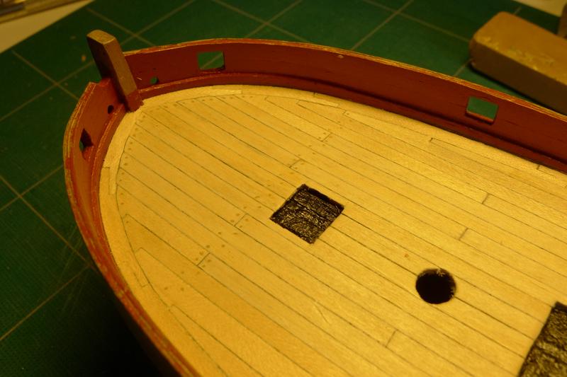
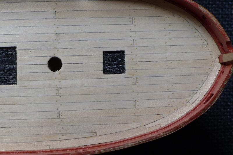
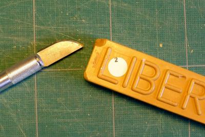
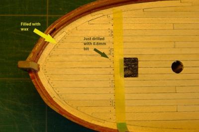
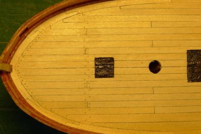
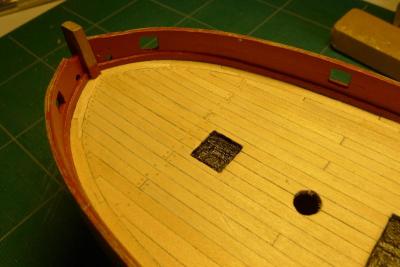
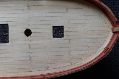
Then, on to the treenailing. I experimented with copper wire but that was too bright and obviously not from a tree. I then thought of bamboo sticks but don’t have a draw plate and won’t buy one as they are far too expensive. So I tried a block of Liberon wax filler stick (Light Oak 02). I had seen Dubz’s photos of pouring molten wax to the deck, but tried instead shaving fragments and pressing them into the holes. I this seemed to give a very nice colouring. I tried 0.8mm holes to mimic 2 inch treenails, but they looked too wide for the equivalent of the 10 inch planks, so I used a 0.6mm drill instead. To sharpen the edges a bit I inserted a 0.3mm pencil into the hole and edged it round, then pressed the wax in. Doing it this way meant the pencil bled a bit into the surrounding plank, so I thought I’d varnish using a polyurethane silk varnish first. You can see the results in the photos following. The pencil did still bleed a bit, and of course the holes I drilled are far from being in straight lines (despite my using masking tape to establish the line). Part of the problem was that I had not been accurate enough in aligning the butt ends of the planks across the deck. Another, and irritating problem, was my choice of continuing with the wider port planks which again meant symmetry was all to pot. All the same, I feel I am learning from all this whilst at the same time have a very enjoyable time finding out some of the ins and outs of this lovely hobby. Tony
- 269 replies
-
- 1
-
-
- Caldercraft
- First build
- (and 3 more)