HOLIDAY DONATION DRIVE - SUPPORT MSW - DO YOUR PART TO KEEP THIS GREAT FORUM GOING! (Only 72 donations so far out of 49,000 members - Can we at least get 100? C'mon guys!)
×


tkay11
-
Posts
1,829 -
Joined
-
Last visited
Content Type
Profiles
Forums
Gallery
Events
Everything posted by tkay11
-
 Very neat and wonderfully fast! Thanks for the ride! Tony
 -
Aaaah! Missed it! Thanks for pointing that out! Tony
-
Very interesting to see another method of making an open boat. I'll be following this with as much interest as your other builds. It's great to have so much enthusiasm that your fingers are always itchy.! Tony
-
Thanks, Adrieke. Sounds reasonable! Tony
-
This is probably a question I should know the answer to, but once the needle is drilled into wood to make the treenail, how is the treenail removed from the needle? (It is obvious I have not yet tried the method, otherwise I am sure I would know the answer!) Tony
-
If you go to the Article Downloads section on the main page of this site, then go to 'Ship Model Material & Tools', you'll find two comprehensive articles on woods for ship modelling and their characteristics which you can download. Tony
-
I know Jotika will cut timber of various types (including pear) to size. Last time I asked they said they could do most thicknesses. Widths around 100mm, depending on wood that they have available. There are of course other wood suppliers, but none that I know of that do kits for a specific model, and none that do laser-cut parts for the kits. However, I haven't done too much research on this and it'll be nice to see if others come up with suggestions. Tony
-
Thanks, Chuck. I didn't know they were on ME, so I can point people to that if necessary. No rush -- just finding out! I quite understand your heavy workload. Tony
-
Chuck, this may not be the right place to ask, but you used to have available for download excellent practicums for the Syren, Phantom, Sultana and Mayflower. I've had a quick look and don't see them any more on the site. I don't need them personally as I downloaded them from MSW 1.0, but someone else was asking about practicums, so I thought I'd mention it in case you were thinking of uploading to the site again for general availability. Sorry if you've already done this and I don't know where to look! Tony
-
Panthere 1744 in 3D
tkay11 replied to malachy's topic in CAD and 3D Modelling/Drafting Plans with Software
Yes, Bava, I quite understand your comment about the difficulties of explanation when there are different CAD packages. I'll have a look at Blender, especially as it can be used on both Linux and Windows platforms, but I'll probably only do this seriously once I have finished my longboat as that is now firmly in TurboCAD and I'm just waiting to render the surfaces and do the internal detail. What I had in mind was something along the lines that SketchUpModeller uses in his HMS Pandora (1779) CAD build log, where he provides a generic description of each step but it is detailed enough to translate to different packages. This is such an interesting area for all modellers and there are so few logs on this site of CAD builds that any ideas thrown into the mix showing the different approaches CAD builders use to their modelling would be very beneficial. It is even more interesting that you have the specific purpose of designing for games, so that would add further to the interest! All the same, it is great that you are posting with whatever time you have to spend on this, so take my comments only as a minor request just in case you feel able to provide more detail. Tony -
Thanks a lot, Alexandru. That is really kind of you, and I am sure many others will benefit from these extra pictures as well. I hope your issues with your internet service provider are overcome! Tony
-
Cool tool lathe Unimat (moved by admin)
tkay11 replied to Sjors's topic in Modeling tools and Workshop Equipment
Very nice article, Ian. Thanks! Tony -
Alexandru, your site with photos of your 34ft launch for the Victory has been reporting the following for several days: "Bandwidth Limit Exceeded The server is temporarily unable to service your request due to the site owner reaching his/her bandwidth limit. Please try again later". Is there any chance of your posting these pictures either with this build, or as another build log? Thanks Tony
-
Making gratings
tkay11 replied to marius's topic in Discussion for a Ship's Deck Furniture, Guns, boats and other Fittings
Very nice photos at that site, Ron. Thanks for posting. Tony -
Garward, this is great stuff as usual. Is the drill you are using for the treenails one of the Chinese ones which will take 0.7mm drill bits? Or can it take a smaller bit. Also, I don't see any wires coming out of the drill. Have you managed to place a battery inside the casing? Or are there wires running into it? Tony
-
This is really excellent! I'd asked on another thread for a step-by-step practicum on 3D CAD ship modelling and had forgotten that this thread is exactly that! Thanks so much for taking the time to do this. I'm now looking forward to the conversion to surfaces as I've been struggling with that. I've also been struggling with the stern of my longboat as the body plan didn't show all the stations so I'm trying to compute the shape of the frames from waterlines -- but so far failing. Tony
-
It is a common refrain on this site that the plans that go with kits are in general very inadequate for the first-timers such as ourselves. It is this problem which means that so many who set out with high expectations give up in frustration after the first few steps. However you'll find that if you take a deep breath, overcome disappointment with your progress and look around on this site, then bit by bit you will overcome each step. Everyone on the site will tell you of their own regrets at not having done it 'right' first time, and that they continue to learn. In fact a lot of the fun is in learning how to overcome each new problem. It may be that some of the practicums that used to be available on this site will be reposted. If so, you'll find very good step by step guides to other models which have plenty of relevance to most builds -- although as far as I remember they were all of solid hull models. However, it would be asking quite a lot for there to be practicums for every model available. It is indeed a pity that the old site went down, because the vast range of kit builds that were posted constituted a pretty good set of instructions for a huge range of models. All the same, the current reconstitution of the site has meant that the situation at the moment is not bad -- especially if you look slightly beyond your own model and look at builds of similar ships. Also don't be wary of looking at the scratch builds. Many of them are incredibly detailed in a step-by-step way, and you'll be surprised at how quickly you start finding things you'd like to do better than possible with the parts supplied with a kit. Another thing to realise, again repeated oft on this site, is that wood is very forgiving, and it is always possible to repair mistakes. Dan Vad started a whole thread on grappling with mistakes which is very instructive. One of the past masters of this craft, Harold Underhill, said in one of his books that there is nothing in ship modelling that is beyond the skill of anyone. It just requires patience and perseverance and the willingness to learn from mistakes. Finally, never be afraid to ask. There is no such thing as a stupid question on this forum since everyone has been through the same process and understands first hand the difficulties. Everyone is very willing to help you out with any difficulty. I myself have benefited hugely from the friendly and highly experienced advice from people here. Indeed I can see that others have already started chipping in. Tony
- 123 replies
-
- 1
-

-
- lady nelson
- victory models
- (and 1 more)
-
Oh, that's brilliant, Allan. Thank you very much! It accords with John's suggestion of less than 0.5mm. Tony
-
There have been a number of negative comments about the Lauck Street site, which you can search for on this forum. With regard to the 'Dummies' site, it was well worth the Can$40, and much better value than a lot of the books that I bought. It also saved me money by making me avoid buying more expensive equipment than I currently need. Tony
-
Thanks, David. I feel a tiny bit guilty at the moment, because I am still trying to build the ship's boat rather than just getting on with the kit (there is no mention of a boat in the kit, and I haven't seen anyone put a boat on the Sherbourne). This has taken up much more time than I thought it would. However, it is great fun learning all these new skills and, as has been repeated so often on this site, 'it ain't a hobby if you hurry'. The thing about the ship's boat is that it is teaching me about drafting and lofting plans from CAD. Then there's the practical side of discovering I can actually carve the shape of a boat from a few bits of MDF (medium-density fibreboard, as it's known in the UK). It may all come to naught when I come to the framing and planking, though! I'm looking forward to your Lady Nelson build. Tony
-
Don't worry about taking pics on your phone, Holty. Lots of people do this. The only thing you have to be careful about, as with any camera, is to try to ensure the lighting is good enough to show what you want. I can't advise you about clinker building as I decided that my cutter was built before cutters were clinker-built. If you want to learn about stealers, there is an excellent planking tutorial available on this site. If you click on 'Main site and article downloads' you'll find an excellent resource on planking. I too cursed when I realised it would have been better to leave off the sternpost till later, but as it turns out, with careful sanding, the result was fine. One way to protect the keel, stem and stern is to put masking tape over them while you sand away at the hull. There used to be lots of good builds of the Lady Nelson on the site before the crash. At the moment I am sure you will have seen Ray's build of the Lady Nelson, and Bettina is starting one as well. However, the Sherbourne build logs by Dubz and Sumner may well be of use to you because the Lady Nelson is quite similar to the Caldercraft kit of the Sherbourne. Those builds have been a great help to me in my own attempts. Also very valuable for great tips on how to manage without complex power tools is the site 'Wooden Ship Building for Dummies' which costs a one-off 40 Canadian Dollars. And of course there are the many tutorials and other brilliant builds on this site. As you look at these other builds, you'll find lots of great tips as to how to proceed and you'll also notice that we all learn from each other. With the better search functions of MSW2, you'll be able to track down specific questions far more easily than before. I'll be following your build with great interest as the Lady Nelson is a lovely ship. Tony
-
What a great idea. Thanks yet again, Garward, for very interesting ideas! Tony
-
Oddly, that might make my job much easier! Thanks very much, John, for the info. I have a lot of wood of 0.5mm thickness. Tony
-
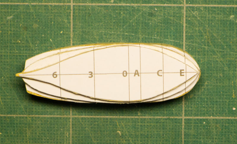
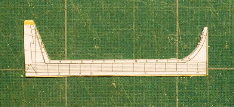
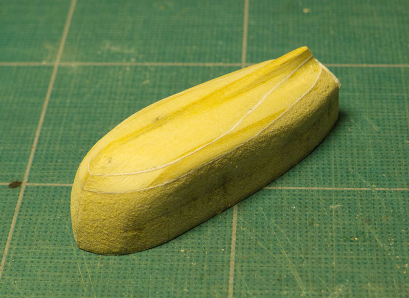
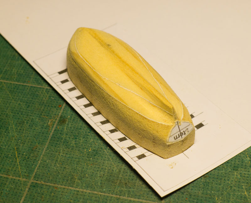
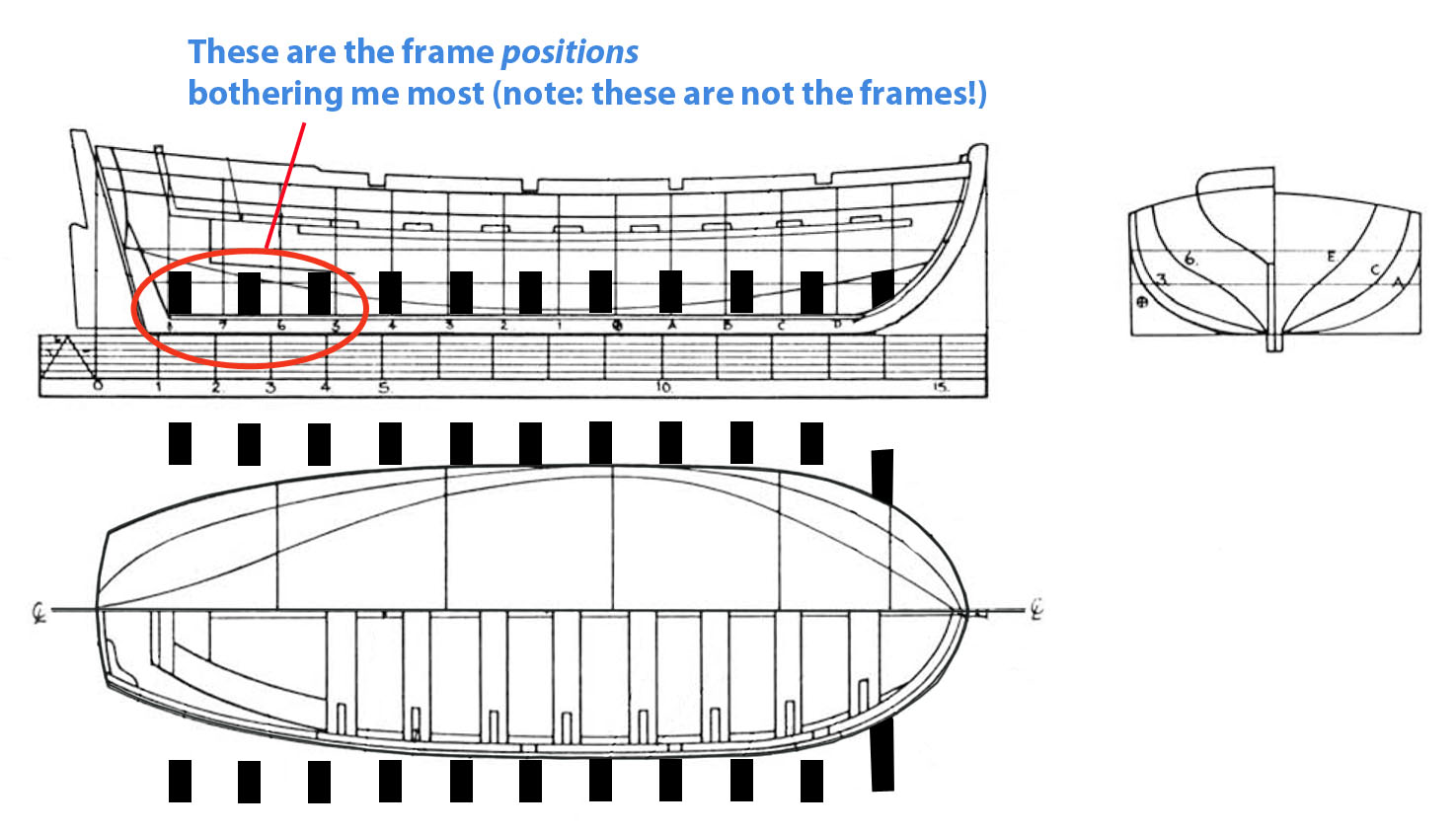
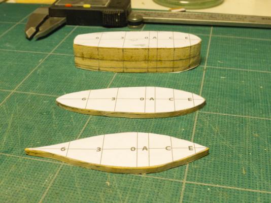
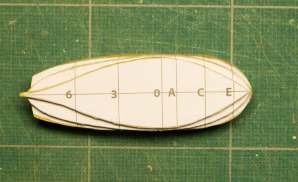
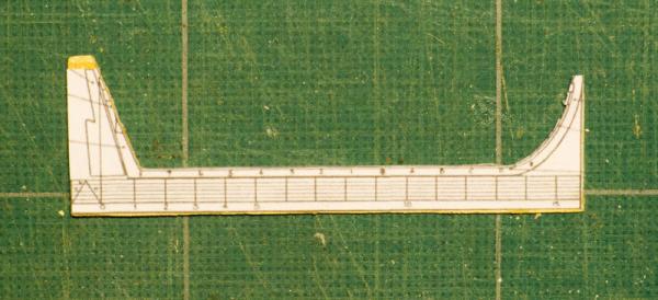
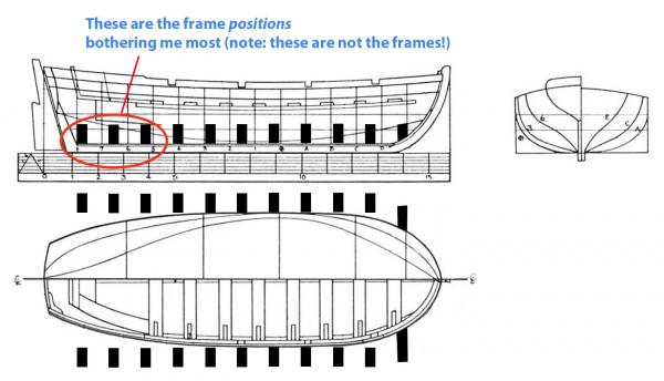
I'm trying (no, struggling) to make a 16ft boat for the cutter Sherbourne. I'm basing it on the longboat portrayed in the AOTS Alert, although zu Mondfeld would probably call it a barge rather than a longboat. The method I am using is one of those suggested by zu Mondfeld in his book 'Historic Ship Models': namely, making a male mould from a wood block and then wrapping frames around it -- from which the mould would eventually be removed. In order to do this, I first transferred the plans to Photoshop and traced them, then re-sized to scale (at 1/64) to match the scale of the Sherbourne. Then, using the cross sections and the sheer plan, I made the mould. This I did not find very hard, and quite enjoyable. However, it was from here that my troubles began. Essentially, my problem centres on the frame size. Having had a look at Chuck's longboat builds on this site, I reckoned a frame made of 2mm x 2mm walnut would be ok, thinking I could wrap frames of this round the hull after suitable steaming/heating. However, the moment I started to think about this in detail, I realised that a 2mm frame would dig in substantially at the stern. If you look at the picture below, I have shown the placing of the frames I was thinking of by using black blocks on the diagram which would show me where to cut the template. I taught myself how to use TurboCAD so that I could experiment with different templates for the frames, but all this has shown me is that I still can't figure out how to approach the frames at the stern, notably for the last three frames I show in the picture. Even if I drop my frame size to 1mm x 1mm the frames at the stern would still intrude. I have a feeling I should build a false keel and then work my frames from there, but I'll wait for any advice. Maybe I'm approaching it in the wrong way, but to start with, I'd like advice on the following: 1. The rough original size of frames for such a boat. I was thinking maybe 2.5 inches square would look about right, which would translate into 1mm square frames at 1/64 scale. 2. Would it be better to develop the framing in a different way? 3. Would it be even better to give up trying this as I'm out of my depth and skill level, and just get on with making the boat as suggested in the kit instructions (there is no mention of a ship's boat in the plans or instructions)? I attach photos showing how I made the layers from the waterlines which I then glued together and then shaped with files. This method allowed me to keep a constant eye on the waterlines as the paper was sandwiched between the blocks of MDF (medium density fibreboard -- as it is known in the UK). So if people spot an elementary mistake here as well, then I'd be grateful for correction, as usual! Looking forward to any available wisdom! Tony


-
Cool tool lathe Unimat (moved by admin)
tkay11 replied to Sjors's topic in Modeling tools and Workshop Equipment
Unimat 3 is one of the earlier, very reliable and much respected versions made in metal, as far as I am aware. The new Unimat Classic is not at all related to this -- again, from what I know. Tony