tkay11
-
Posts
1,829 -
Joined
-
Last visited
Content Type
Profiles
Forums
Gallery
Events
Everything posted by tkay11
-
 Ebay's a good idea, Martin, and I'll certainly look there. It's the adapter I need, though, to fit blades from other manufacturers, since I have the Proxxon blades. Proxxon seem to have their own unique 10mm spindle which is not the norm for other manufacturers. Tony
 -
Hmm, Wacko (I like the sound of that more than Joe, and hope no offence taken). Might just be a good excuse to buy a lathe. Costs a bit more than the shipping, but maybe if I put long term costs to the Admiral for budget approval.... Thanks, though, for the suggestions. It was the shipping and import costs that put the Byrnes machine out of reach for me. But I really do like the Proxxon, and I have gradually become more adept at using it. I'm now down to doing 1.6mm strips of 0.5mm walnut without a problem, and probably will manage smaller. It's what made me think of doing gratings as I am a bit dissatisfied with the main grating on my ship at the moment. Tony
-
I would like to buy a Byrnes saw blade of .030 kerf to use with a Proxxon FET table saw. The only trouble is that his saw blades are for a 1/2" spindle and the Proxxon uses one of 10mm. Jim has told me that he only makes adapters to go to 1". I have seen an adapter in MicroMark for $6.50 that will do this, but as that is based in the USA and the shipping for that alone to the UK is $18.50, the price would be exorbitant for such a simple and small adapter. So my question is whether anyone knows of such an adapter in the UK (or perhaps Europe) that would make such an adapter. My search on the web so far has not turned up anything. Or is this something I could make? I don't think I have the tools to do it -- I imagine a lathe would be necessary. The reason, by the way, is to make 0.8mm gratings. At present my saw blades are 0.6mm, 1.1mm and 1.2mm. I haven't seen a method of making gratings with an under-sized blade, but if you know of a method of doing this then please let me know. Any advice or suggestions welcome! Tony
-
Thanks a lot, Wayne. I do agree about the kit -- a really nice kit for beginners. I hadn't seen your Sherbourne, so I've been mulling over that and your Granado. It'll be a long while before I can achieve the crispness and tidiness of your finish on both the wood and the rigging (which has yet to come for me). And the tiller you made on the Sherbourne has made me think of re-doing mine. It seems I have a thing or two to learn about tillers! Also a very interesting remark you made about blackener benefiting from heating. I'll be trying that next time. My own feeling is that once I have completed the Sherbourne I'll want to move into building from plans rather than a kit. The experience with the ship's boat has shown me the challenge, the possibility and the sheer joy of achievement in working from plans. Tony
-
Just a further comment on 'easy'. I think what I meant by 'hindsight' relates to the thinking involved. When I start out on any of these numerous 'mini-projects' that are part of the overall build, I am often very hazy about how exactly I am going to do it. So off I trot doing a search on the forums, looking at other builds, reading books. Then I think a lot about it while walking or sitting in a plane or having a beer until I can visualise in my mind's eye just how I can take each step, with which tools and, most importantly of all, with which compromises (and as a novice I accept many more compromises than those who have already been through such processes many times over). I'd say that is the hard part. Once it's all visualised, it then becomes 'easy' until I realise that my visualisation is not quite correct and I come across an unexpected outcome. So the process of visualisation starts all over again. The building part, being a mix of foolhardiness, dexterity, learning how to use good tools, patience and perseverance, seems much easier. Tony
- 269 replies
-
- 1
-

-
- Caldercraft
- First build
- (and 3 more)
-
Thanks a lot, guys! I very much appreciate the comments. I don't know about 'easy', Carl. It's always easy in hindsight and after finding a way to overcome a problem -- and this is one of those very rare occasions in which the photos look better than the model. Mark hits the 'mark' (groan, I put that in before realising the pun) when talking of 'perseverance': that, and learning from mistakes. Next time round it will be much easier for me. Thus I've certainly unglued and re-done quite a bit of it a few times over. For example, I realise now it was a bit presumptuous to dig out a rabbet: the planks never did quite fit into it so I messed up the keel irreversibly (unless I carved it out all over again). Then the sternsheets were first made out of a single piece of cherry that didn't fit correctly and looked totally out of place -- so I had to re-do those from walnut strip. And the thwarts went through two iterations before I could get their width and spacing better (for some reason I had mis-set my vernier calipers first two times round). All that and the problem I had with the sides coming away from the keel a couple of times as a result of the pressure I was putting on this fragile little shell. However, I thought such tribulations would be regarded as commonplace by the experienced crowd here, so I thought it better to leave all that out. Thank goodness for isopropanol and its power over PVA glue! And thank goodness as well for all the experience on this forum that gave me the courage and ideas to go about the whole endeavour! Yes, John, you're right. The tiller needs a lot of work. I mention in a photo that it's only on the way to completion but didn't clarify that in the text. I just thought I'd post the photo as I was pleased at thinking of a way to attach it! I hope the final result will be a little more realistic! Thanks again for keeping to pop in and give encouragement! Tony
- 269 replies
-
- 1
-
-
- Caldercraft
- First build
- (and 3 more)
-
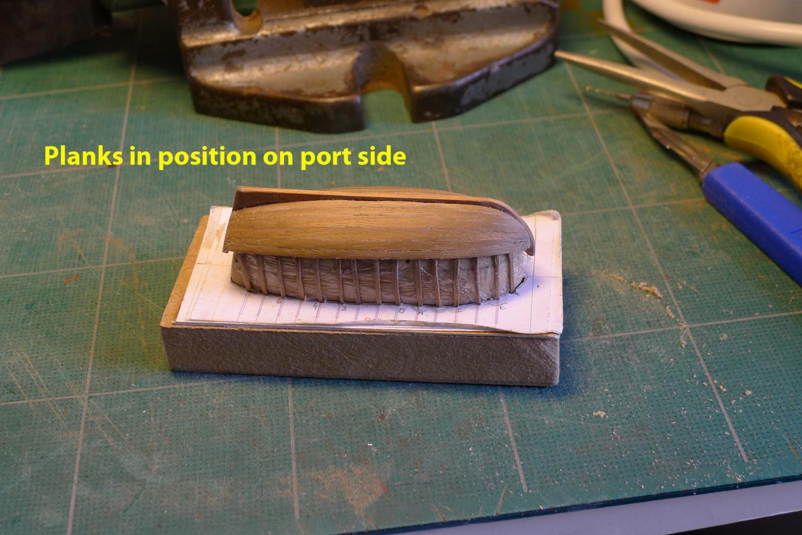
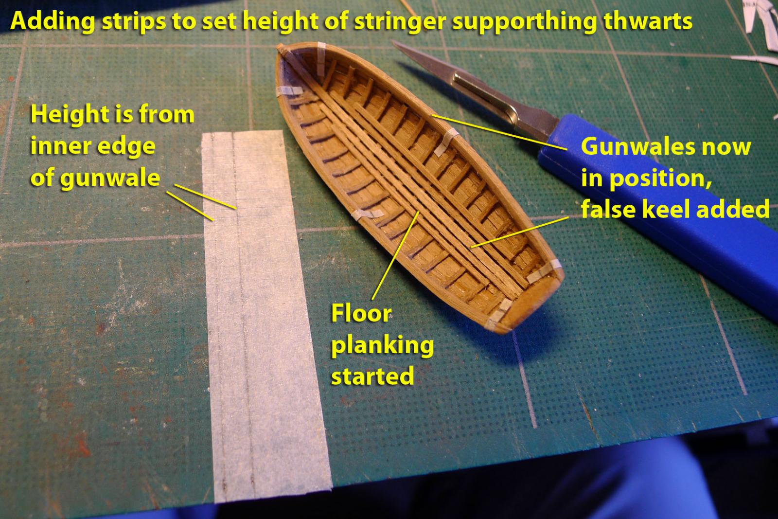
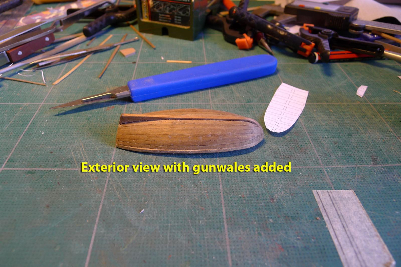
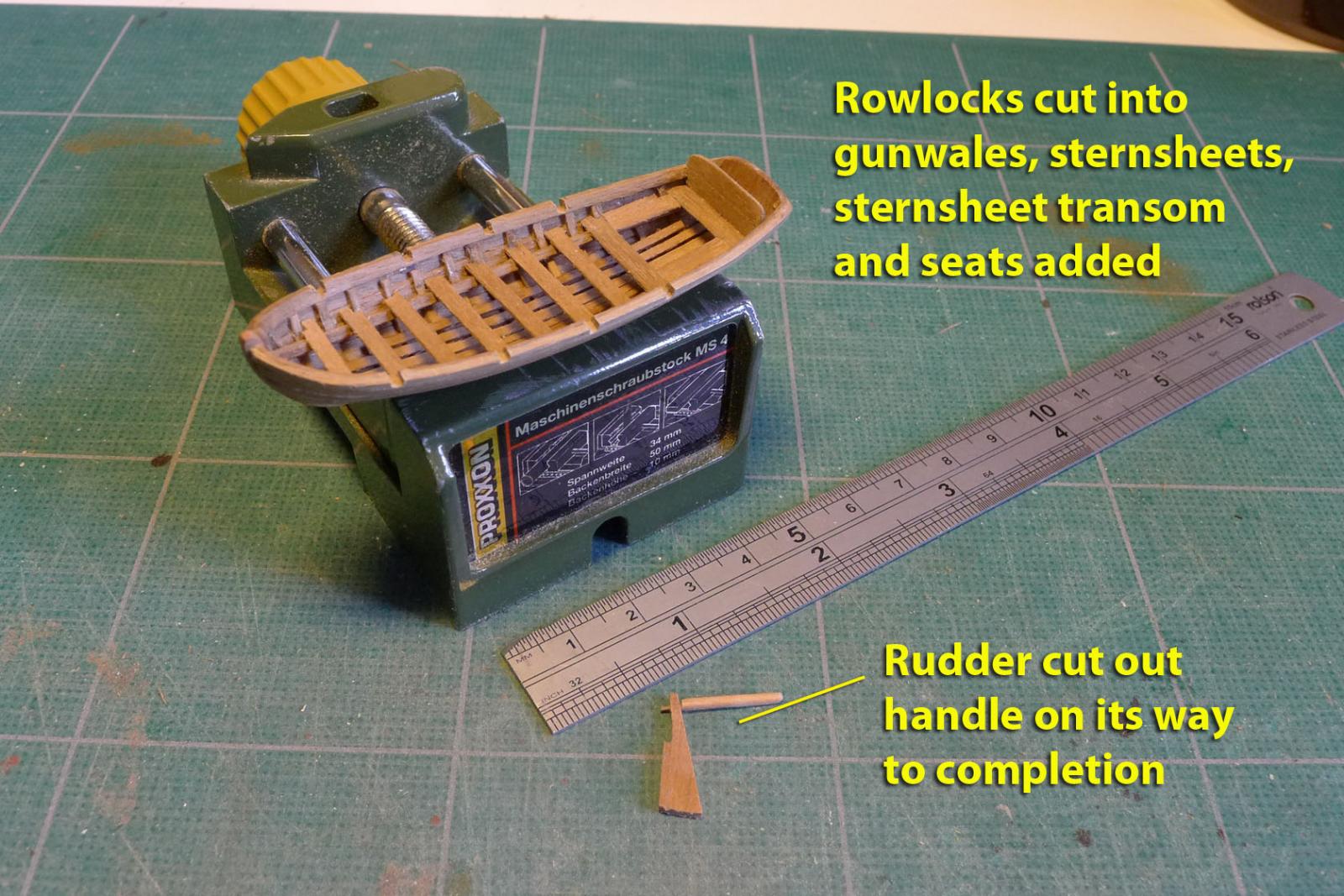
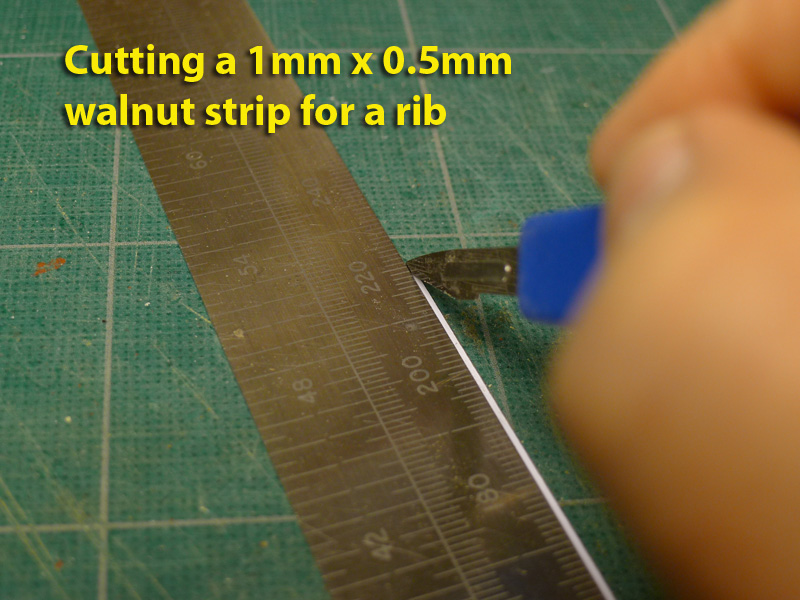
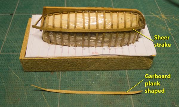
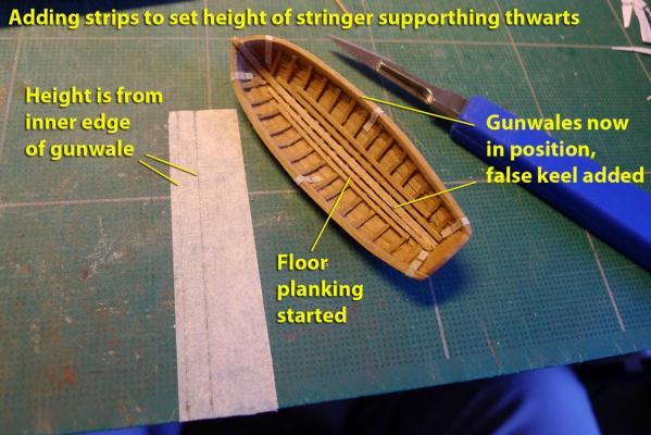
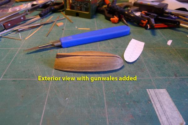
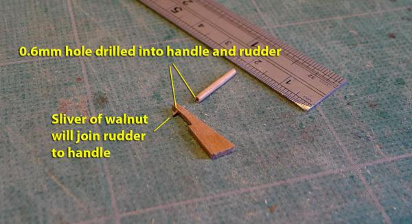
The Bank Holiday weekend in the UK allowed me to make a little bit of further progress on the ship’s boat. First on was the sheer strake. I reckoned that would be good to place first because then I could estimate the number of planks between that and the keel. I then cut out the garboard plank, as seen in the photo. Shaping the planks was a bit easier than I expected – but this was mostly because I didn’t spile them correctly and just tapered one side of each plank! Having finished the external planks, I could remove the shell from the mould, cut away the ribs from the point where the gunwale joins, and then add the gunwales. That was a moment of magic for me -- it really did look like a boat shape! It may not have the magnificent carpentry of the other ship's boat builds that are on this site, but I had managed at least the rudiments and it certainly boosted my morale and my appetite to continue! I made the gunwales by gluing a 1mm square strip of walnut to a 0.5 x 1mm strip, then bending appropriately. By the way, I now use a small soldering iron to do the bending. I do this after soaking the planks and allowing them to saturate. It really is quite a nice sound to hear the hiss of the steam as I apply the plank to the iron, and watch it (the plank, that is: not the iron) dry and bend. After putting on the gunwales I cut strips from masking tape to show me where to place the stringer supporting the thwarts. You’ll see the strips in the photo. Then I laid a false keel along the keel top, and started the floor planking. The next stage was to cut away the rowlocks into the gunwales. This is not really accurate, as the gunwales I added are thicker than the plans recommend, but I compromised! The sternsheets, sternsheet transom (made from strips of 0.5mm walnut) and the seats were then added. The rudder was then cut out, a handle made from 1mm square cherry, and 0.6mm holes drilled into the handle and the rudder in order to join them with a sliver of walnut. I’ve had a bash at the thwart knees, but so far have not found a nice way of doing them. I might give up on that score. I’m also debating about the position for a mast. However, the most immediate work to do will be the gudgeons and pintles for the rudder, and the oars. The only real problem is the mix of walnut and cherry (apart from an obvious asymmetry in the height of the sides and the spacing of the ribs). That came about just because of the wood I had to hand. I had started the ship's boat more as a proof of concept -- not really believing I could make one. Now it's beginning to look like a real boat I am loathe to do it all over again. I decided I'll put it all down to experience for the build of my next ship's boat! And now, back to the work that pays and funds the ship modelling (among other things). Tony


- 269 replies
-
- 4
-
-
- Caldercraft
- First build
- (and 3 more)
-
Thanks, LFrank, I had a look, but it's based in the USA and also the strips there are no longer sold by them or out of stock. I'm really looking for a UK supplier to avoid heavy shipping costs. Tony
-
As a matter of interest, Norman, where were you able to buy 0.5mm cherry from? Was it in the UK? I'd be glad to know because I need 0.5mm cherry to finish off my ship's boat. I've been using 1/16 and 3/32 cherry board which I found at Cornwall Model Boats, but haven't yet found a supplier of smaller strips. As a result I had to do the ribs using walnut and the combination looks a bit odd. Tony Tony
-
Here you are! http://www.ancre.fr/manuel19-e.htm Tony
-
My only comment is that I have a problem with 4-head pin vises because the tiny bits tend to slip out of the vertical more than in those with three heads. But maybe that's a problem only for me! Tony
-
You can also get pear in a range of thicknesses at Jotika. You have to ring them to place an order and they say it takes about 3 weeks to deliver. Tony
-
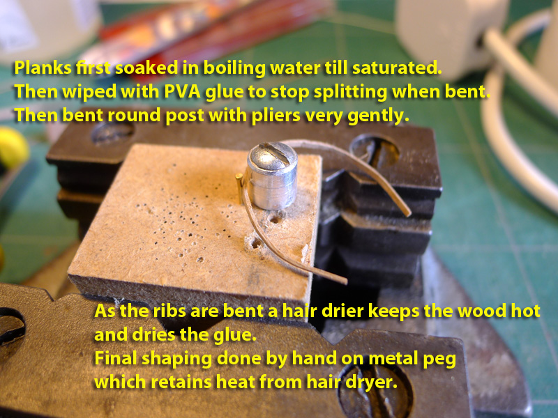
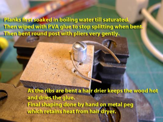
I haven't used cherry, but I used walnut to make the frames on my ship's boat. I used 1mm x 0.5mm strips, soaked them in boiling water until they sank, then wiped them with PVA glue so they wouldn't splinter. Then I very carefully and slowly bent them round a post using a hairdryer to play on them. The heat not only allowed the wood to bend, but dried the glue and made the curve firm. I was able to achieve the same kind of bend as you are looking for. The key was doing it very gently. For the first round I held the wood in pliers while the hairdryer was on. This also heated the metal post I was bending the strips round and it retained its heat for some time. Whilst it was still hot I completed the bending by hand round the post. Tony
-
Thanks, David. Yes, it's great that this forum is filled with people learning from each other . Very convivial, educative and enjoyable. Tony
-
From my own experience a kit labelled as 'easy' or 'beginner' could mean that if you just follow the instructions given and use only the parts provided you can put it all together and obtain a model fairly quickly. I reckon I could have finished my kit of the Sherbourne in a few months if I had done that. The trouble is that as soon as you do some research on the web and come across a forum of enthusiasts, your eyes are opened to what is possible. As soon as those eyes glint with the challenge, you are then drawn into a series of tweaks and alterations that will take up as much time as you want or have available. If you take on a kit labelled as 'difficult' the expectation of the manufacturer is that you are already aware of tweaks and alterations that might be necessary and have already had experience doing that. So they deliberately play the game you want. Think of it as a computer game. In a computer game there are often different levels of 'difficulty'. This just means that the manufacturer of the game knows that those who attempt the more difficult levels already have some knowledge of the 'rules of the game' and the skills involved in order to achieve it. Most humans will be able to reach the top levels with perseverance, but with practice and knowledge. Humans like puzzles and challenges, and ship modelling includes lots of both if you want them. The time for the completion of my kit has been lengthening ever since I joined this forum, and also since I found I was having more work to do outside of ship modelling. Each new piece or stage of the kit brings new skills and challenges not that I have to learn, but that I want to learn. As I learn those skills I find myself more confident of wanting to make parts more accurate (or faithful to an original) and taking on new skills. Some of these skills may not be entirely necessary. There is an air of masochism to the obtaining of some detail. For example may modellers like to be sure that observers can see the treenails on decks and hulls even though on real ships they are barely noticeable. Is this accuracy or showing off or personal satisfaction at getting to that 'level'? I don't know, but on my ship I decided not to show treenails on the hull, but did so for the deck. For me it was a matter of obtaining a skill. If I hadn't done it, I would still end up with a lovely model and as I don't know any other modellers in my circle of family and friends, nobody would have known the difference. It is up to you how far you want to go and which challenges you decide to take up. Whatever you decide, it's probably best that you do it because you're happy to do it and not because others have done it. Whichever way you choose, you can be fairly confident that those around you who have not done any modelling will admire the work you put in. My family look at my model as it grows and say they are amazed at the detail and skill. I try to explain that it is nothing like the skill of others, but to them it is a thing of beauty. And the truth is that I am amazed at myself as I achieve each new stage. I can't possibly rate what I have done in terms of 'difficulty'. I can only rate it in terms of satisfaction. And that is very high indeed. Every model can be as difficult as you want to make it. Some of the supposedly 'easy' models are difficult because the instructions as so awful that people give up. Just some thoughts! Tony
-
I very much admire the way you allow the rigging to hang. Excellent work! Tony
-
As far as I know, primer is useful in that it seals the wood as well as allows for better sanding. However, I haven't used primer. Just multiple coats of diluted acrylic paint together with light sanding between coats. I should mention, though, that I have still a lot to learn about finishing surfaces! Tony
- 123 replies
-
- 1
-
-
- lady nelson
- victory models
- (and 1 more)
-
Thanks, John. I'm glad to know you're still keeping an eye on me! Tony
-
Thanks, B.E. Totally agreed -- really worth sticking to it, whatever the outcome. Tony
-
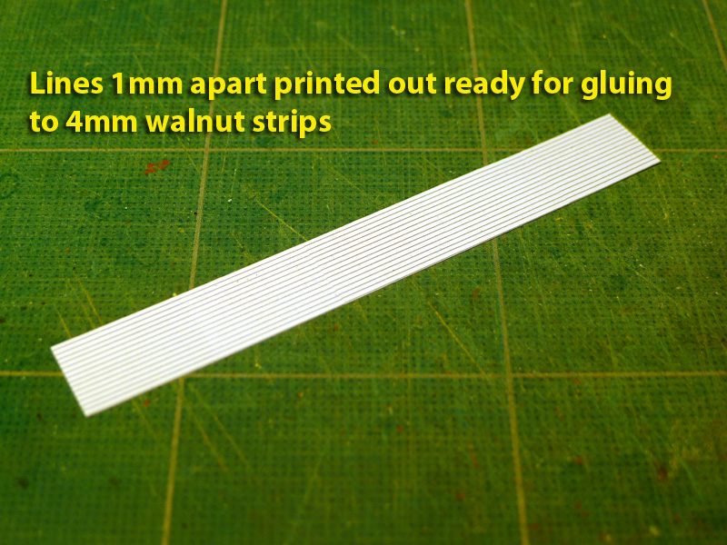
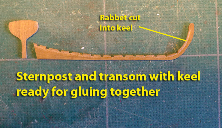
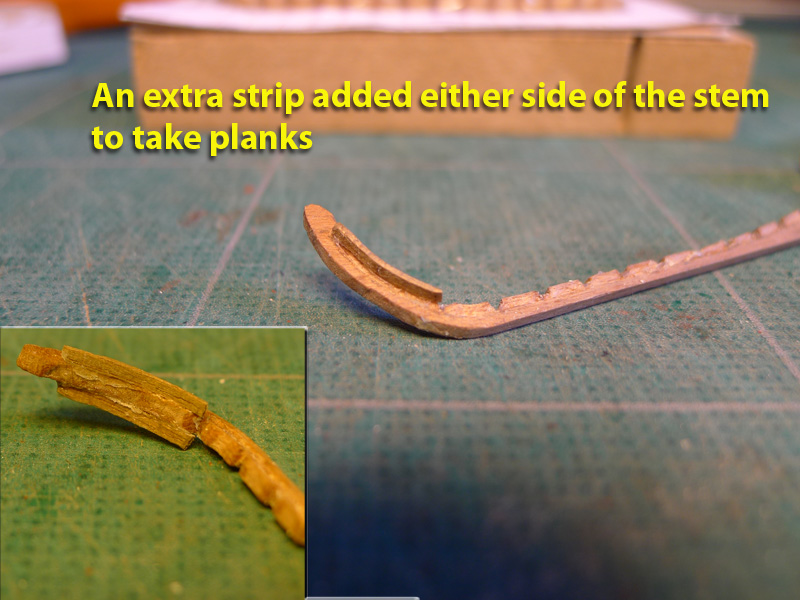
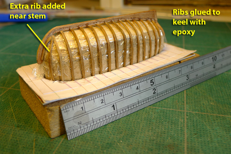
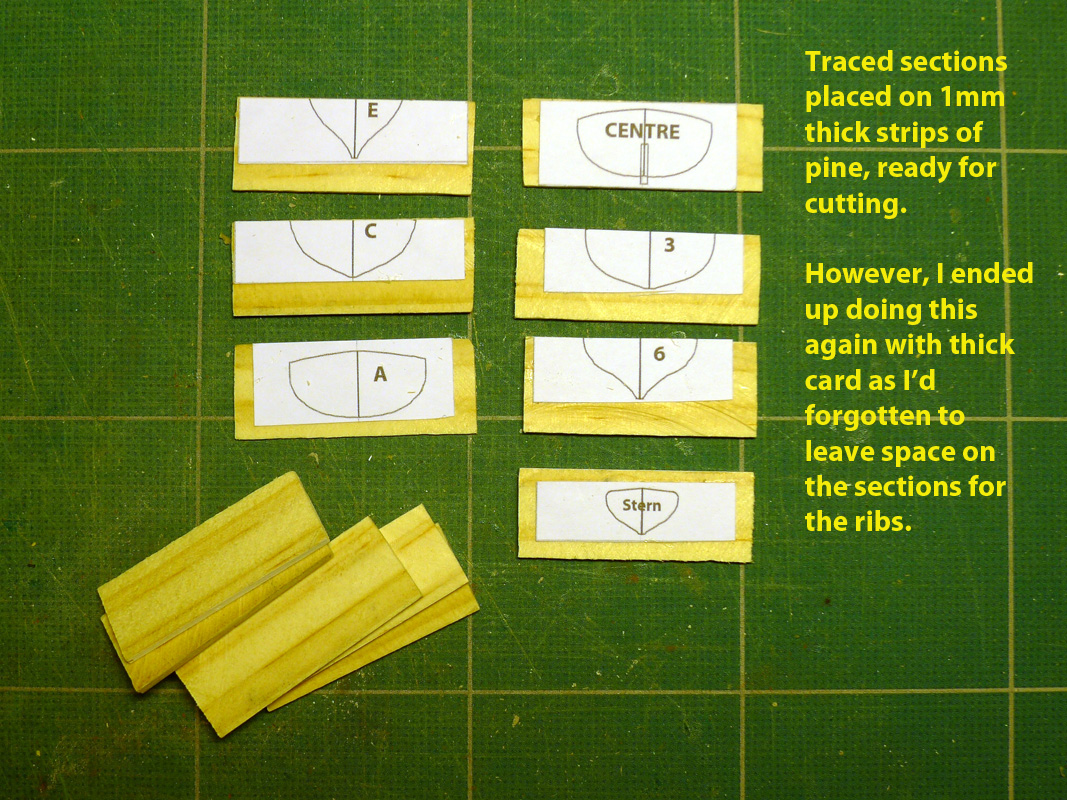
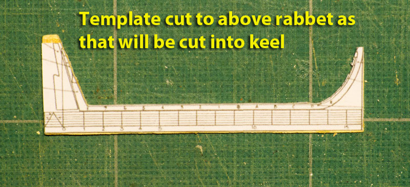
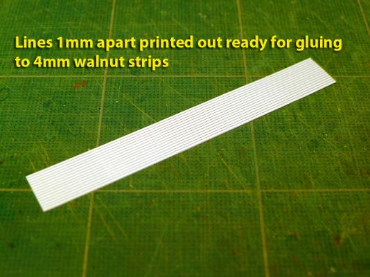
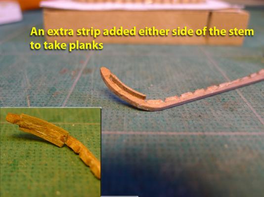
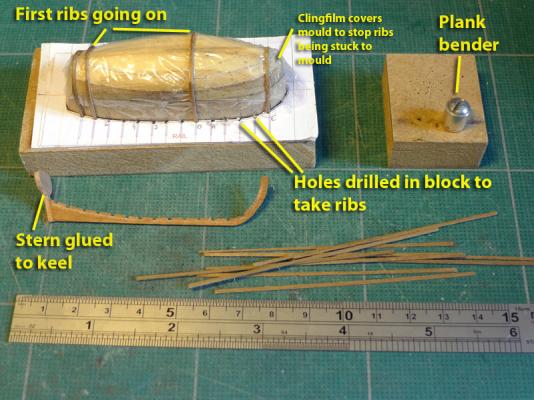
The next stage was to make the ribs. I decided that the easiest way of doing this would be to print lines 1mm apart in the CAD programme, paste these to 4mm x 0.5mm walnut strips and cut them out using a scalpel. After enquiring of others on this site the size to make the ribs, it was clear that if they were to be to scale they should be 0.5mm x 0.5mm. However, I found that my accuracy in cutting would be best left at 1mm x 0.5mm. I estimated the length needed for the ribs by sticking sellotape to the outside of the mould and marking off the top edges, then laying the sellotape on a board and measuring the distance. The first attempts at bending these very thin and narrow strips to the hull showed that I needed to improve my technique. Simply soaking in water then bending as had been done for the main ship’s planking proved impossible as the ribs simply fractured along the sharpest parts of the curve. I was able to overcome this problem by wiping the soaked planks with PVA glue. Whilst they were still moist, I then slowly bent them round my plank bender whilst playing a hair dryer on to them. At this stage I used pliers to hold the end of the rib as it was far too hot to allow my fingers anywhere near the assembly. This allowed the planks to benefit from direct heat, as well as to dry out the glue very quickly and hold the shape of the curve. The curve was finished by holding the rib to the still hot post of my plank bender and shaping it till it matched the shape of the mould at its position. The keel and stern were then glued with epoxy to the ribs, and an extra rib added by the stem to act as further support for the planks at the bow. I then made a block on which to place the mould, pasted the breadth plan to some thick card and cut out the pattern. This pattern was stuck to the MDF block. The reason for the thick card was to provide a space which would hold the mould to the block. I then drilled 1.2mm holes at each station point around the template as shown in Milton Roth’s book ‘Ship Modeling from Stem to Stern’. These holes would then act as ‘locks’ for the top parts of the ribs. A rabbet was cut into the keel with a scalpel. The sternpost and transom were then cut out of 1.6mm cherry sheet and glued to the keel. Extra strips of wood were added to the stem in order to provide a hold for the planks. PVA glue was used to do this. Clingfilm was then used to cover the whole mould, and the shaped ribs were inserted over this into the receiving holes of the template and block. The clingfilm stops the ribs or planks being glued to the mould – thus allowing the mould to be removed easily once the planking is completed. So right now I’ve reached the basic stage of having established the basic shape of the boat. Next step is to do the planking! One of the problems I foresee is the length of the boat and how it is supposed to fit on the ship. Skippy decided he’d tow his behind the Sherbourne. I’m still thinking about this. Maybe one day I’ll even get back to the kit of the ship I’m supposed to be building. Tony


- 269 replies
-
- 1
-
-
- Caldercraft
- First build
- (and 3 more)
-
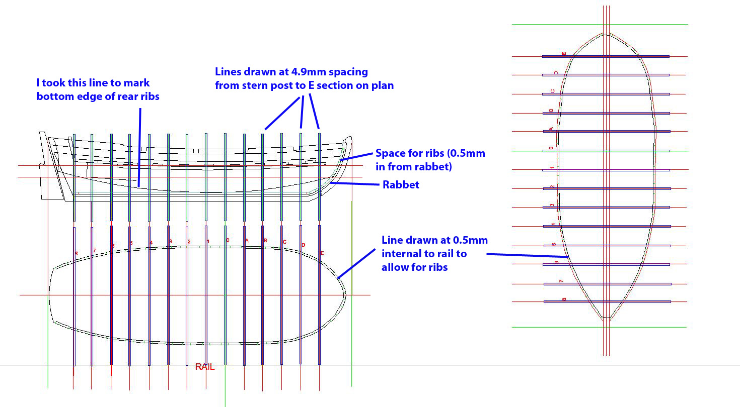
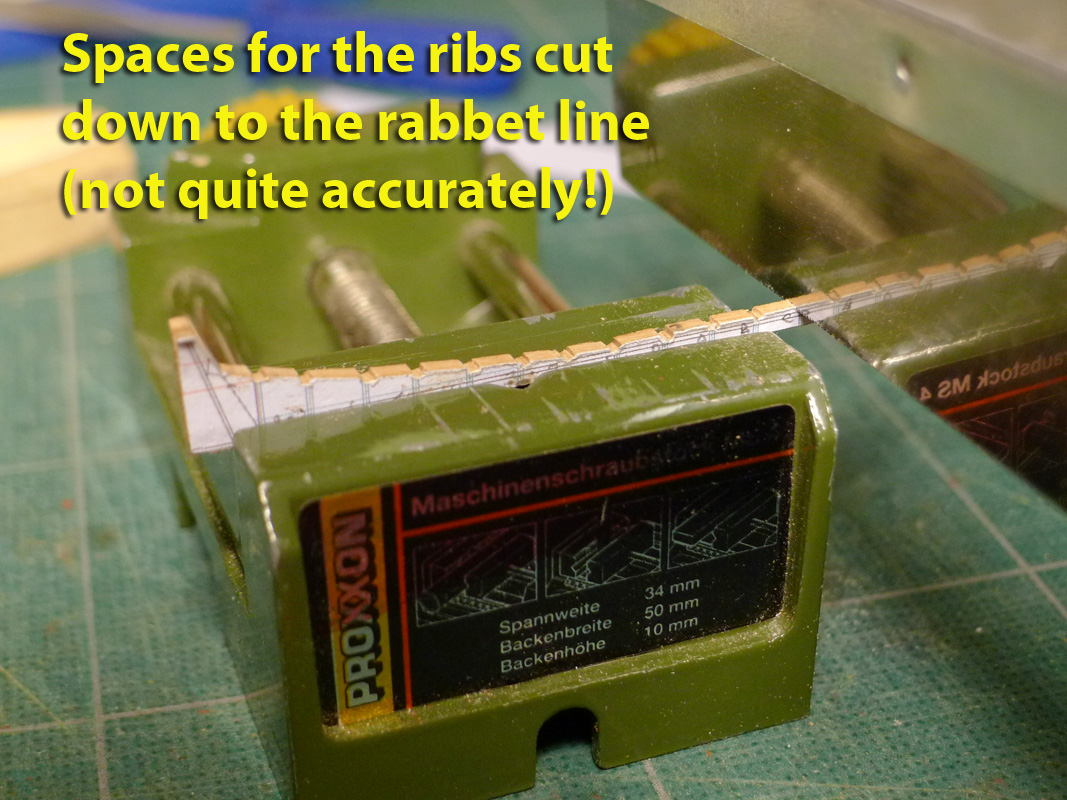
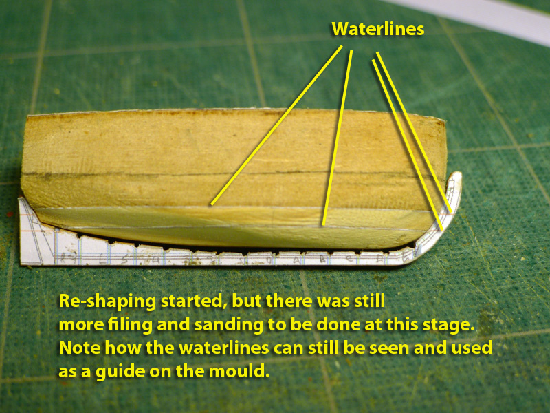
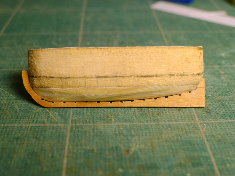
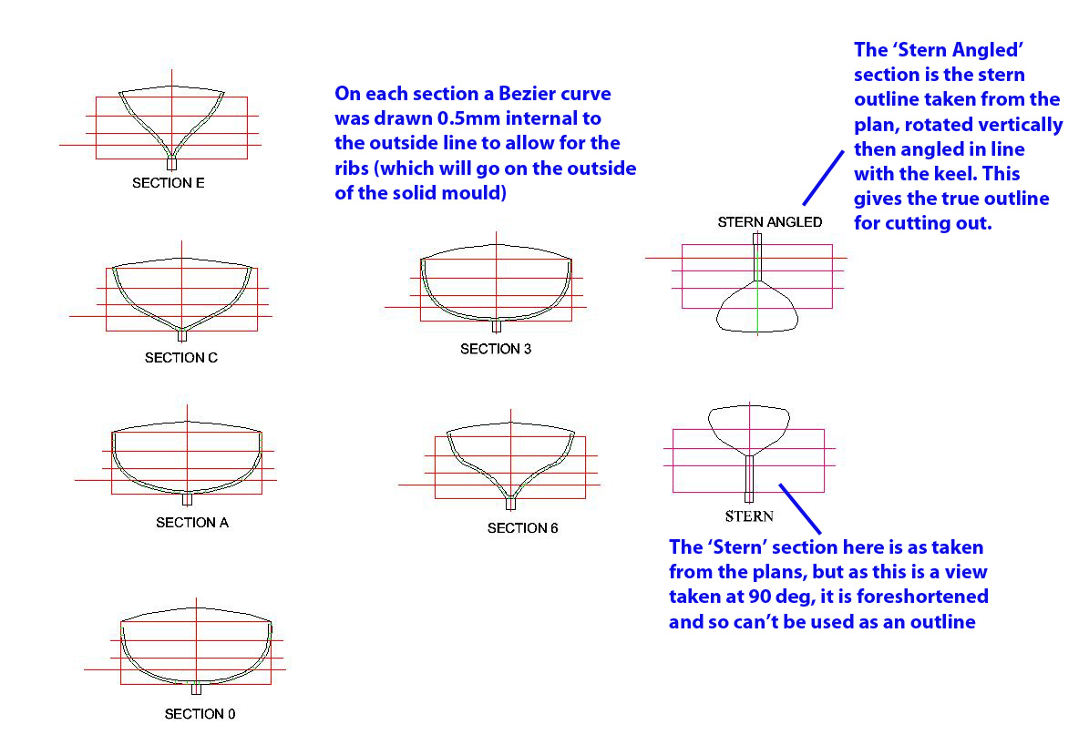
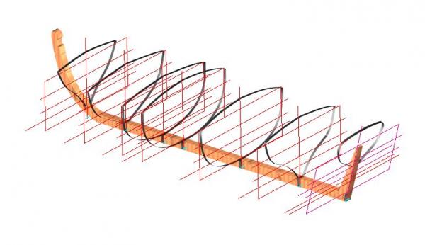
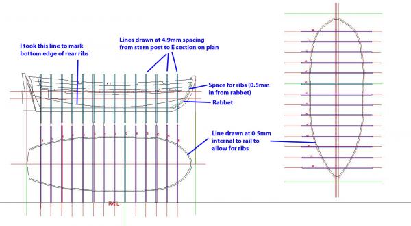
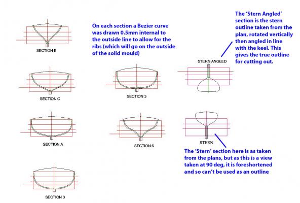
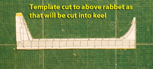
THE NEED TO RE-THINK! It was at this stage that I realised that I had not thought of some essential aspects: I hadn’t figured out how the keel at the stern end would be shaped and then after looking more closely at Alexandru’s build I realised I would have to make the keel taller at the stern. I hadn’t allowed for the fact that the transom and stern post on the plan were seen from the rear at 900, and therefore had to be corrected for foreshortening if I was to have a template for the transom. I hadn’t allowed for the width of the frames on the mould, since they were going to have to lie between the mould and the planks. It was at this stage that I almost gave up on the enterprise, and either make a ship’s boat using one of those made by Jotika, or not to have one at all. However, on reflection, I thought that I’d gone so far and it was all in the pursuit of learning how to model boats, so I persevered. I therefore decided I’d have to have another method to make all this more accurate, and that meant using a CAD package rather than Photoshop. And that in turn meant I’d have to learn how to use that package since I had minimal experience of CAD. Last year I had been lucky enough to have a colleague who no longer wanted his CAD package as he found it too complex, and he gave me his TurboCAD 19. I had fiddled with it a bit at the time, but got no further than tracing and using that to make the cannon trucks. Now it was time to get more serious. After learning the ins and outs of Bezier curves, I eventually was able to make a 3D model which gave me a good idea of what I was aiming at. The sections then had to be re-scanned and an inner line drawn 0.5mm from the outer edge to allow for the ribs. This was done by drawing a series of 0.5mm lines perpendicular to the outer Bezier curve, then linking up the vertices of those lines with another Bezier curve. You might notice on the picture that I have the 'Stern Angled' and 'Stern' views muddled, but you'll get the idea! Then the sheer plan and waterlines were re-drawn, again using the same method to draw an internal line to allow space for the ribs. At the same time, the stations were re-drawn so that I could use them as frame (or rib) placements. This was done by fitting a series of 14 vertical lines equally spaced between the junction of the keel with the stern post and the foremost section (E) on the original plans. Then two lines were drawn 0.5mm forward and aft of each station line to represent the ribs. These station lines were then drawn on each of the waterline plans in order to allow making of a jig that would hold the whole assembly. I was able to see from the scanned plan that the aft sections could follow what had looked like a buttock line. I therefore cut the keel out of 1.6mm cherry and filed down the mould to this new shape. This time I also allowed not only for the rabbet, but also for the ribs. I cut out the rib spaces on the keel using a saw and needle file that was luckily the same width as the ribs (1mm) to a depth of 0.5mm or so. To check the depth I used a strip of 0.5mm thick walnut strip. You’ll notice from the pictures that my sanding of the block was not accurate for sections 0-7, and that I filed away too much from the mould. However, because of the method I was using I reckoned it was unimportant since the important thing was to have space to glue the ribs to the keel. Tony


-
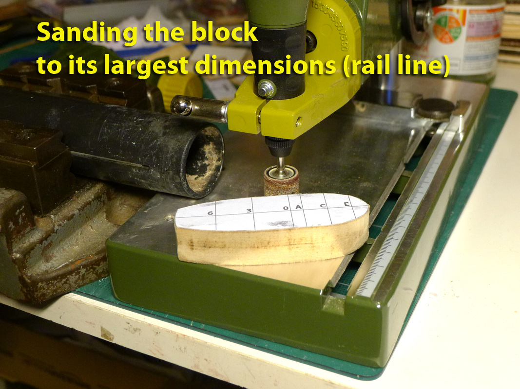
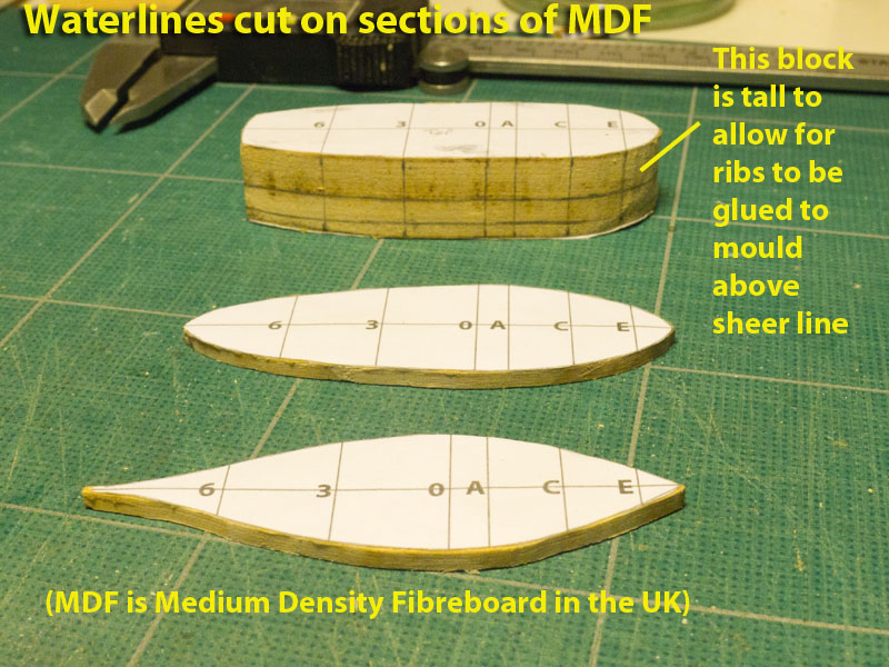
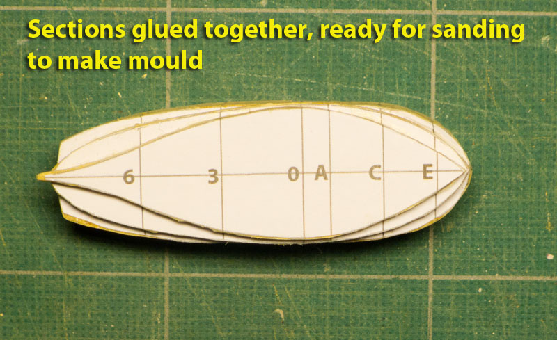
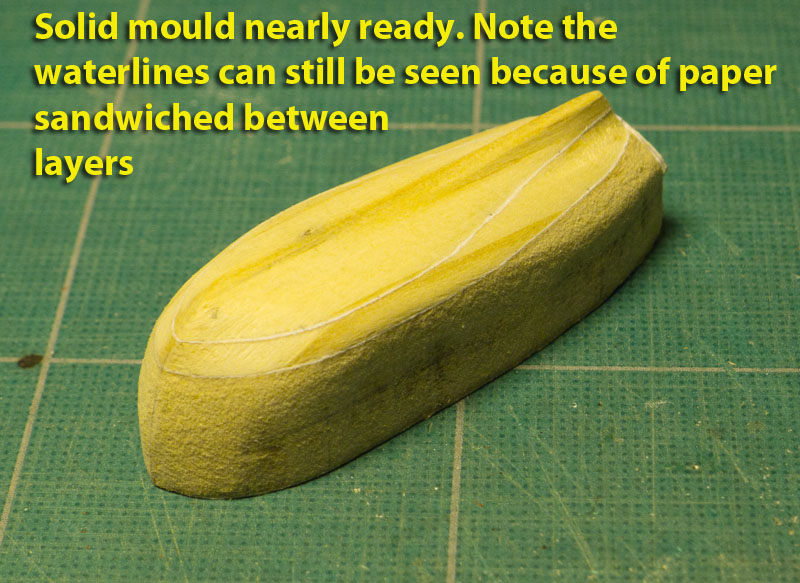
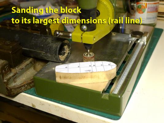
After reviewing all the methods of making ship’s boats (electro-plating, carving and hollowing out a shell, building up round a solid mould), I settle on building up round a solid mould as recommended in Zu Mondfeld’s book ‘Historic Ship Models’. This was partly because there is an excellent build of ship’s boats on this site by Alexandru using exactly this method. You can see that at http://modelshipworld.com/index.php?/topic/1474-34-ft-hms-victory-launch-by-alexandru-scale-148-completed/. So I studied that, as well as the explanations in other books, and plunged in. The first step of this process was to paste templates to sections of MDF (medium density fibreboard) which were cut to the height of each waterline section. Others had built the whole block in one go, but I thought that by building it up by waterline I could keep a good focus on aligning the templates to the mould as I filed down, and at the same time this would give me a rough guide as to where to file. As recommended, the section representing the rail was made much taller to allow for the ribs to be glued to the solid mould above the sheer line but not to the mould below (allowing the mould eventually to be removed). I used a sanding drum on my rotary tool to make sure of the overall maximum dimensions of the uppermost block, then glued the sections together. Then using the templates of the sections and the sheer plan, I was able to file and sand the block down to a rough shape. Tony


- 269 replies
-
- 1
-
-
- Caldercraft
- First build
- (and 3 more)
-
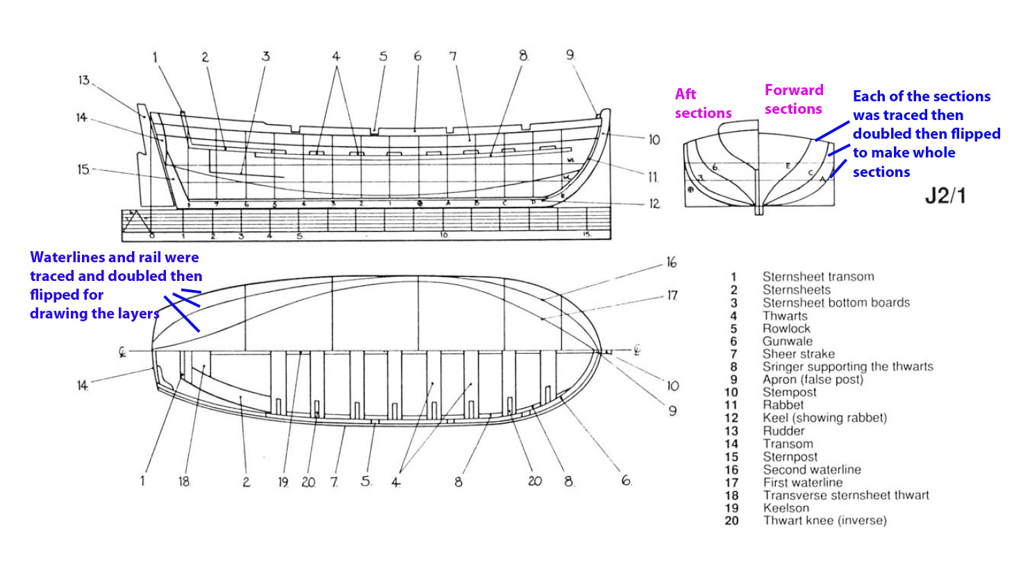
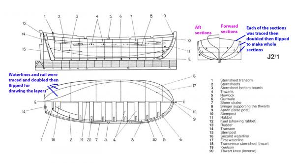
Having prepared the cannon and the shot holders, my eye drifted around the deck and I wondered about the absence of a ship’s boat in the kit. Clearly if one was to be built, it would be better to do it before work on the masts and rigging. So I decided to see whether I could build one. This decision has taken up a very large amount of time since it meant I had to learn a lot of new skills. First thing to do was to decide on the boat. The Anatomy of the Ship book on the Cutter Alert has plans for a 16ft ‘longboat’. Since the Alert had roughly the same dimensions as the Sherbourne, I thought it reasonable to use those plans. So I took a scan of the page of those plans and traced them in Photoshop. Since the half-breadth and body plans only show half a section, each half was duplicated and flipped to make up the whole sections and waterlines. Tony This allowed me to make a page of the sheer plan, the sections and waterlines that I could print out ready for cutting as templates. Tony

- 269 replies
-
- 1
-
-
- Caldercraft
- First build
- (and 3 more)
-
That planking has come out very nicely, Holty. It seems you're well on the way now. I also found a bit of a problem with the wood, but more because I wanted to have wider planks rather than more, and also because I wanted to do the second planking with 0.5mm thickness strips. So I bought extra wood from Cornwall Model Boats. As to your other questions, I leave that to the experts. But everything I've seen points to sharp corners for the gunports. For the wales, I found that in my kit there were special strips for that (two strips on each side). This did not mimic the original practice, but it did make them much easier to build. For filler I used the sawdust from filing and sanding and then mixed this with dilute PVA glue. Leave it to harden just a bit and then apply. That way you have a filler that has the same colour as the wood you are using. Staining and varnishing is up to you. I toyed with this but in the end settled for painting most of the hull. For really beautiful finishes to preserve the wood colour some use oil, others use a matt silk varnish. I used Ronseal satin clear quick drying varnish which is water soluble, so easy to clean off. However, I prefer the finish given by linseed oil and probably will use that much more in future. You'll find an excellent guide to oils which clears up the confusion as to types and names at http://www.popularwoodworking.com/techniques/finishing/oil-finishes-their-history-and-use. The advantage to using the varnish is that it will still allow the use of glues after varnishing. Tony
-
Thanks, Skippy. I too thought of buying one of the Jotika boats. I think there's a 12' version available from Cornwall Model Boats for about £15, but I thought that if I gave in after all the time and effort I've devoted to trying to work out how to build one it would be a complete waste. As it turns out, I've now completed the keel and ribs and should start planking once I return from my current trip in Northern Nigeria and the follow-up work I'll have to do once home. I should be able to send some pictures of progress so far. It's interesting that you've chosen the same colour scheme as I have for your Sherbourne and I hope my effort will turn out as nicely as yours. Even my boat is too long for the Sherbourne at 16', so I'll either keep it separate as you have done or else make a smaller boat now that I'm beginning to see how it all can be done. And thanks B.E., too for looking in and your kind comments. Value for money it certainly is: huge amounts of fun, endless learning and totally absorbing whenever I can find the time to devote to it. Both (Skippy's and BE's) of your posts stimulated me to look at all your builds. I hadn't seen them before (edit: no, I've just realised that's not true as I now remember I had a good look at BE's build of the boats on Pickle) and I really have enjoyed what I have seen so far. The descriptions and research you've both done are very interesting -- in addition to the fact that you both have created such beautiful models. I'll now be following your builds with attention and once I'm home I'll be looking them up especially for the details of the rigging. I noticed also the detail about the rudder cover -- something I've been thinking of attempting. Tony