Walter Biles
-
Posts
356 -
Joined
-
Last visited
Content Type
Profiles
Forums
Gallery
Events
Everything posted by Walter Biles
-
 Hi Bob, glad to see you back. I'd like to learn how to do frames like that on the Spray. They come out looking like the real thing. Walt Biles
 -
Yes, I had the all button marked on the printer, but only the first page printed again. I also tried it in Print Preview with all selected from my browser, but I only got page 1. Walt
-
Thank you Michael. I am slowly working my way through getting everything to fit together correctly. I would also like to have the CAD plan drawings correct so if anyone would like to build her, I can supply a set of reasonably accurate plans. The real one sailed very nicely. Walter Biles
-
(A bit of mental musing to decide proceedings from this place.)(I am actually using this build log as a tool in planning) I have shimmed the assembly slots on the bulkheads to bring the deck into line on the keel frame. The fairing is in close condition but untried by planking strips (Just Eyeballed). In earlier versions in cardboard, I assembled them in double thick corrugated cardboard, and cut them out with the plan pasted on them to check the markings. Where necessary I adjusted or replaced any bad fitting frame parts. Then I cut out the bottom keel part and found that I was not allowing enough material between the keel and bulkhead cuts, so I re-did a new set with more space between. It was a juggling act to get it to work. Finally I started it in plywood. It is coming along although I did not get the right depth on some of the notches, they were close enough to shim. Now I am going to have to go back to my CAD and make the adjustments there. Then if I am satisfied with CAD-Wood frame fits, I can proceed to true up the frame with blocking after I get a jig made to hold the keel straight. At that place I will be ready for more pictures. MARK, IS THERE A PRINT FEATURE FOR THIS BUILD LOG PAGE? If I do CTRL-P I can only get the first printed page. Even if I do curser select then CTRL-P, it still only gets the first printed page. I'd like to check if my mind shows continuity in the presentation. ie. a good report for the readers. Walt Biles
-
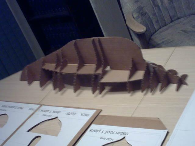
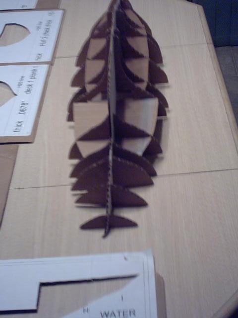
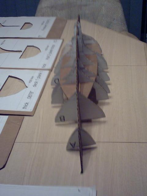
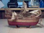
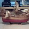
My first Ship from 50 years ago A "Monster cat from the deep" ravaged it, and it sets here in the deep six as it was then.

-
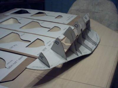
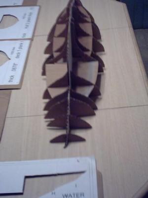
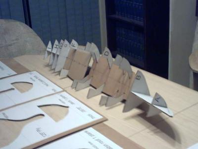
These are the pictures from the first Cardboard mockup I did of the hull. After I got them all cut and fitted, I let my little neighbor boy come over and "Help me build the boat frame". He's In kindergarden or first grade this year, and was thrilled to be thought of for the job. It didn't take long for his part, and I'm going to add some cardboard "planking" and give it to him, if he wants it. I learned more about 3D interferences doing these mockups. I did 3 through the hull framing, learning about where the interferences were. This ends my posts for tonight. Walt Biles


- 208 replies
-
- 1
-

-
- meridea
- repair ship
- (and 1 more)
-
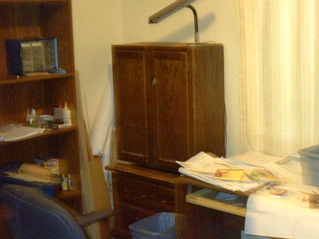
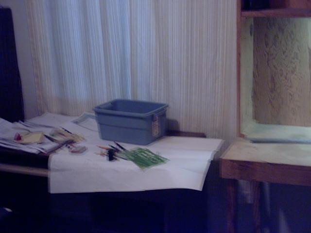
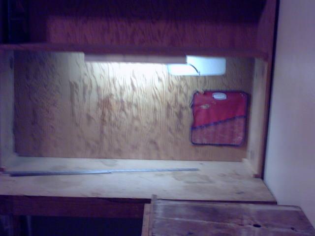
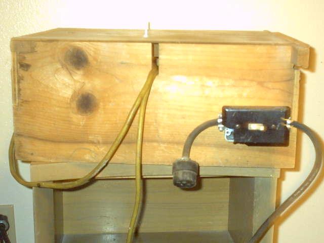
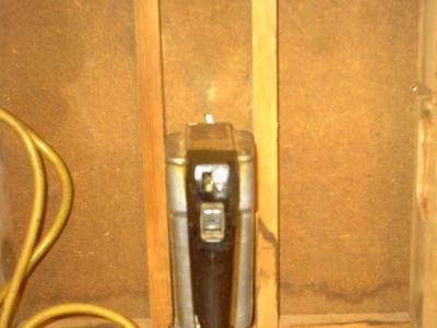
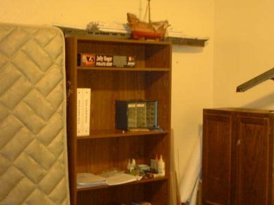
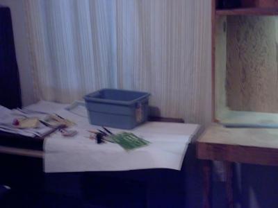
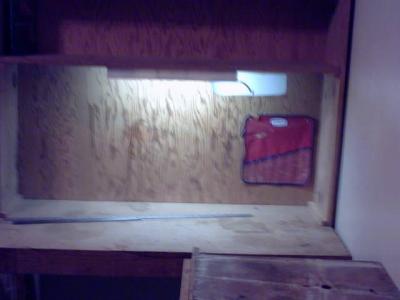
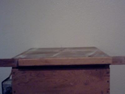
This next set of pictures will be of my work shop which is also part store room. On top at the back of the cabinet is 53" cardboard "Titanic". Left front is plastic Aircraft Carrier 10 "Enterprize" At it's stern is my Balsa POF Spanish Galleon (Cat ravaged when I was in the navy. Built 50 years ago in High School.) My storeage cabinet and light stand next to my work desk. My other work bench. This shows my old Stanley jig saw in the little table I made to put it in so I could do scroll cuts back in the 1970's. The motor on this 50 year old tool finally fried itself last week. The 3 wheel 10" Craftsman bandsaw that I have had for a long time will not stop jumping the blade off the wheels. I believe it is the tires on the wheels. I need to save up for another set of parts or else get the Scroll Saw that I think will be more reliable, if I can get the money together. Walt Biles


-
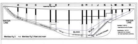
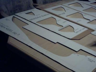
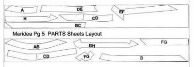
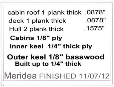
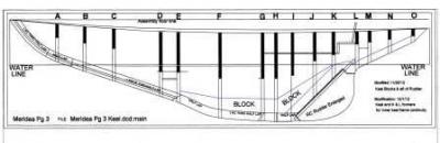
This one is the pieces of the built up outer keel, hoping they are correct in their overlaps. This is an information panel about wood sizing.
-
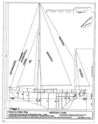
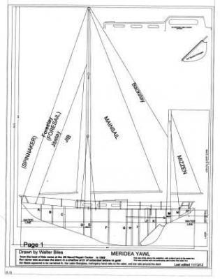
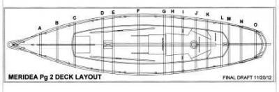
Thank you Mark. These drawings are not totally correct. I have some of the former lap cutouts for the keel in the wrong place for a true fit. I found this out while I was doing my wood cut pieces as I was assembling them. I have to go back over the cad drawings making sure all the corrections are there. I did 3 cardboard mockups of this thing finding mistakes here and there each time. It has been a long road, but the wood one is coming out close to fairable in both the hull and deck planking shapes. I will not start any final assembly until I have all the part matching entered in CAD. The full group of drawings all to the same scale. This shows an extended cabin option as well as the original cabin. The Hull side and sail plan. The Deck plan The hull side plan with the former positions and cutouts for the keel former and the deck and cockpit deck and seat shown. I still see some of the working part companions on the bulkheads that need cleaned up. These plans are no longer valid. They had to be redrawn much fuller to provide the lift to hold the hull up on the waterline. July 20, 2014 The test float left the waterline almost 1/2" below the water surface. I will repost these drawings when I get the new float test done, which may be several months from now due to my distraction from my wife's health concerns. See Log page 10 for amended All plans 9/4/2014 Walter Biles
-
Could some one please help me with the way to upload my pix to this forum? I'm stuck Walt Biles
-
Original boat estimated at 38'...... Scale 1:13.3 ............Model length 34.2" This is from a hand scaled drawing I made from the seawall at Severn River Repair Station about 1969. About 1990 I began entering it into my DesignCAD program to try to preserve the disintegrating grocery sack drawing, always thinking it would make a nice RC sailboat. Having worked around those boats for almost 1 1/2 years by then I had seen many of her type both in and out of the water. I liked her lines and the way she looked sailing. Her sail booms and mast were made of what appeared to be plywood on both sides with filler planks across the narrow cross section. They were finished in marine varnish. Her hull and decks and cockpit and cabin were all done in fiberglass. She had mahogany handrails along the top of the cabin, mahogany 2.5" toe rails around the edge of the deck. Her masts were guyed with wire cables. She did have cleats for adjusting the running rigging. I don't think she had a motor, because she always dropped the remaining sails as she got close to the slip and coasted in slowly. My Meridea original was a fiberglass mold hull, coupled with a fiberglass deck, cockpit, and cabin, but I can not make moulds to do that type of structure. Because of this, and the fact that I had always intended my model to be radio controlled, I have built it as accurately as possible, but had to make concessions to the fact that I had to make a frame that could hold wood to bring out the shape. Then due to structural integrity, I had to strengthen parts of it by adding bulwarks to make someplace to hold the railing stanchions where they would not be broken off the model too easily. There was actually only stanchions with plates bolted through the fiberglass deck, with a small toe rail with water slots cut through it next to the stanchions. I think, she was a prototype, to try out optimal handling designs. I had never seen rectangular masts of wood, and her running lines disappeared down into the masts, most likely, to below deck electric winch controls. You could say that my prototype model imitates her. I would like to try to make my model try to achieve in a model that which Meridea was doing as a boat: One person handling. My prototype model varies considerably from the real boat. But I felt these concessions were needed to give a knock-about model the strength I needed. Once I have gotten this prototype built and can do considerable testing to determine what is necessary for the RC version, I may be able to make a more realistic actual scale model that would be more historically accurate. I still strive to be historically accurate, but I have to work within my medium, wood, for now. Later when I get a shape I can build a mould of, then I may be able to seek to atain historical accuracy. Even that will be illusionary, since I was never on the actual boat and can only go by what I have seen of how such a casting of fiberglass would have been done back then. This will be the realization of a life long dream I had back then of seeing if I could do a sailing model of her. I will begin with a few pictures of the plans I have drawn on CAD in 2 dimensions of her.