Walter Biles
-
Posts
356 -
Joined
-
Last visited
Content Type
Profiles
Forums
Gallery
Events
Everything posted by Walter Biles
-
 Thank you Mark, Ed, Michael, Popeye, and Bob for the likes and the comments. Walt Biles
 -
Nice job on that stern Popeye! Walt Biles
-
I'm back from almost a week away at my daughter's house. I got a great blessing today. I have inherited 4 kit form boats, two of which had been started. I now have AL Constellation 1798 at 1:85, a Constructo Cutty Sark 1:90, and a Constitution by Constructo at 1:82 which I will mostly have to scratch finish from the plans and what is left of the kit, and HMS Endeavor 1:80 which I will probably restart from the plans as a POF redrawn for a scratch build using the fittings left from the kit. The lady who was doing them, died from MS several years ago, and her husband gave them to me since he knew I would enjoy them. On top of that I have MS plans for Fair America and Constitution which I got from Model EXPO when they had them on sale this past year. I am rich in prospective builds. I have seldom worked from any kit except for a couple of block hull Blue Nose schooners I did in the '60s. I still have quite a bit of bass wood from my Meridea that won't be used up by the time I finish her, so I have options for once, and can actually learn what it is like to build from a kit. I've mostly built scratch from a plan, or a plan that I scaled and drew myself. I am thrilled. First I have to get back to finish my Meridea. I think I will experiment with the Endeavor plans and see if I can draw and build it from what I've learned about framing boats here as a POF. Since I can basically use the same scale, all I'll need to do is create extrapolations of the frames in between the ones already there, and allow for some fairing in between the ones I have the shapes for. This could be very interesting and exciting. Walt Biles
- 208 replies
-
- 1
-

-
- meridea
- repair ship
- (and 1 more)
-
Popeye, Wonderful job on the color and decoration scheme! I think I have figured out why they made such a bunch of colors, patterns and such. An approaching ship seeing that scheme is so awestruck and anxious to see all of it, they are within pistol shot range before they are too close to the opened gunports to see their danger!!! Like a moth to a flame!!. Seriously though. Great job!!!!!
-
Nathan, I do believe that you will find at least one of the numberous diagrams and descriptions in that book will be of use. I found a used copy, and I would have been lost without it. Although I have done many airplane RC installations, I had never done anything for sail control. I have not built the RC into my boat yet, but am feeling confident of doing so, due to this book. The diagrams are good, and the explanations in the text helped me understand the whys and hows of the features. It will be up to you as to whether it would be of value at that price considering your finances, but I was very glad I found it. Good luck with your boat. Walter Biles
-
Ed, Even prior to page 24 some pictures show, some do not. Just the red X and a file name like the link has been lost. I was logged in so that is not the problem. Walt Biles
-
Using chisels for turning brass
Walter Biles replied to tkay11's topic in Modeling tools and Workshop Equipment
Tony I have not worked with the mini sized tools, I just felt it is better to know all you can before trying something. Walt Biles -
Using chisels for turning brass
Walter Biles replied to tkay11's topic in Modeling tools and Workshop Equipment
Tony, Nobody has come out and explained the difference between wood turning with hand tools, and metal turning. if you are transitioning from a mini lathe with wood and tools, you might not realize it. On wood tools the angle of grind on the cutting edge of the hand tool is very acute. It is designed for working wood. Another factor is that wood has grain and if the wood grabs the tool, usually it is the wood that will break out in stead of the tool being buried into the wood and yanking the tool. With metal the cutting edge on the cutter is very near to square by comparison. The tool is usually held in a mechanical anchoring clamp for safety and for a more stable angle of attack on the metal. If the metal tries to chunk off the work, the tool is so well locked down, that it can very nearly not move the tool. In that situation, the work has to give in shear or else take the edge off the tool. That is the kind of grab that you would not want to be holding on to if your lathe has much power. Does this help in understanding why a metal cutting tool usually is held clamped into a holder? Also any kind of lathe work is best done with a full face shield in case something flys toward you that you would not want buried in some part of your face or neck. I generally would use a helmet attached face shield with a more powerful lathe. Walt Biles -
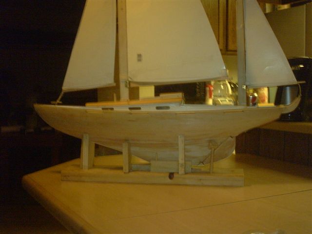
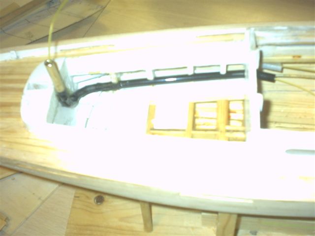
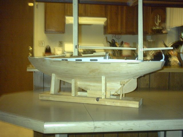
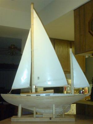
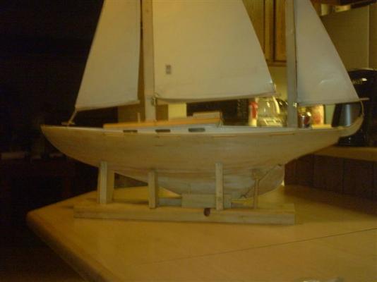
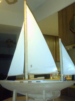
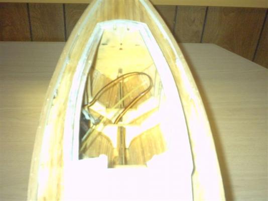
Here are some pictures of her. Note the Mizzen boom control riser at the stern. I never would have been able to close haul the mizzen with the old one. Here is what she looks like with her sail patterns pasted to her. I put a temporary line up to hold her Jib.
- 208 replies
-
- 7
-
-
- meridea
- repair ship
- (and 1 more)
-
Thanks Mark and Bob. I have another section to do, but I will need a bit more of the thicker brass, and the line for rigging, and especially the turnbuckles that are on the way to me. I want to redo the masts, and that will take a new ball tip dremel bit. If I can do what I want, I think I might be able to simulate the sliding ball and track on the masts and booms. That was a feature I really liked, and if my equipment is up to it, I think I might be able to pull it off. I would have to cut the track before the mast edges are tapered. I also would like to make those through the masts channel for the sail running lines. That way if I can get a good multi-channel radio, I may be able to do the sail raising and lowering by controls. That would be the cat's meow! I am going to put up a couple of pictures of my boat all rigged out (sort of, no lines are in yet.)
-
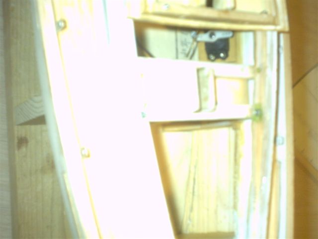
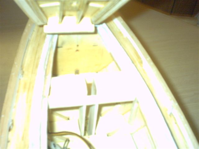
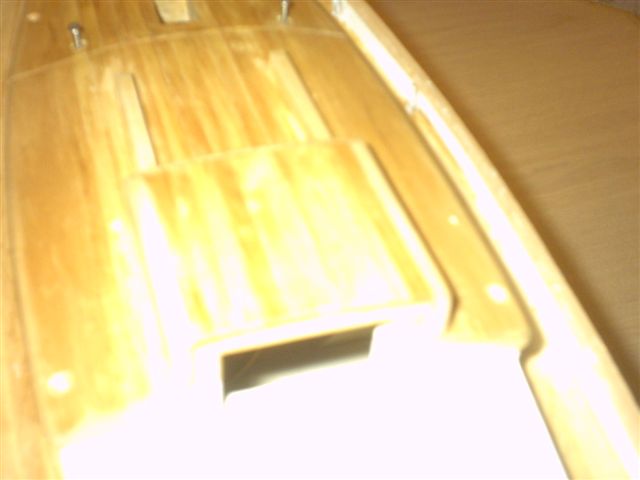
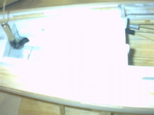
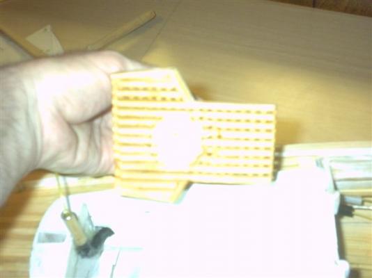
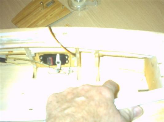
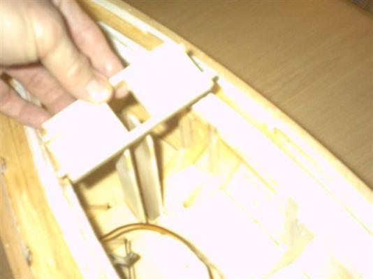
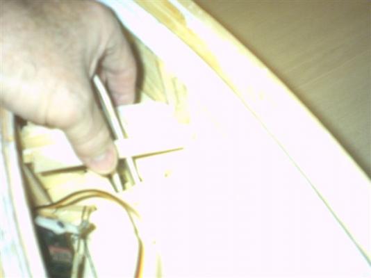
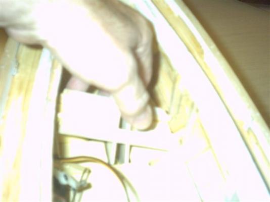
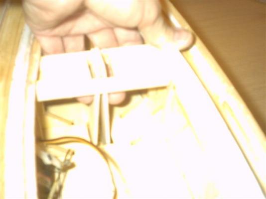
Assembling the components of the boat Part 2 The top fwd roof piece is laying upside down to show the groove in it that the ends of the upright mast guides fit into. The roof helps lock them down when it is screwed down. Note the 2 green highlighted areas with the screws. These will help to lock the upper cabin framework into the Mast Collar Guide. Here they are seated. They hold things in line while the roof top is installed. This shows the grooves on the underside of the roof girder getting to slip below the angled roof supports toward the front of the cabin. As it slides foreward it will bring the roof down onto the rubber gasket around the cabin frame at the front. When the roof is fully foreward, let the back of the opening for the mast down over the mast guide uprights. Here you can see that the mast guides are not back in their notches. With a finger I spread the guides so they are now seated. the two screws are ready to pull the roof down and draw the mast collar assembly together. The next two screws are ready to hold the roof edges down on their gasket. You can see the aft roof section with its allignment pins and the gasket on the slip under ledge at the front part of the roof section. the aft roof has entered the pin holes which helped the gasket ledge to slip carefully under the lip of the foreward roof. Pressing foreward and down, to seat the back edge of the aft roof section. The companionway hatch cover may be slid foreward, and the screws at the aft roof corners are ready to go in to hold the roof onto its gasket. After losing two sets of the hatch slide boards, I am in need of making a new set again. This ends this part of the assembly.


- 208 replies
-
- 2
-
-
- meridea
- repair ship
- (and 1 more)
-
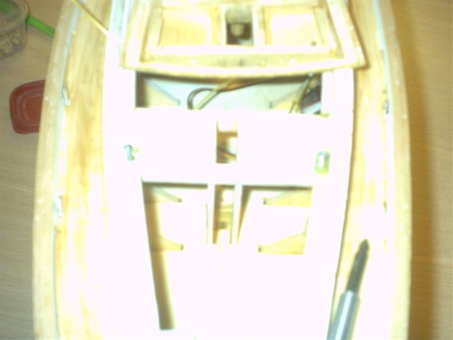
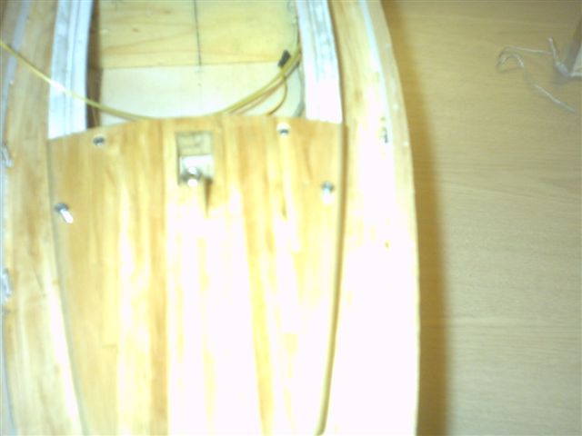
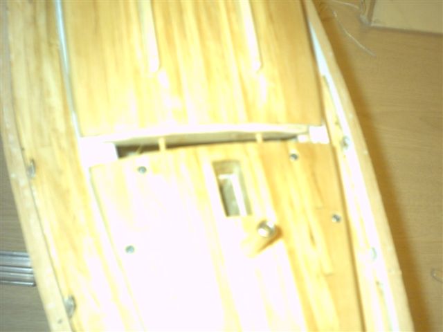
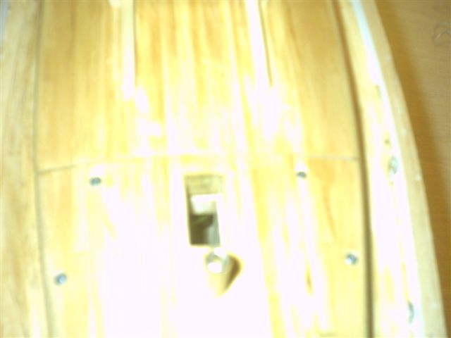
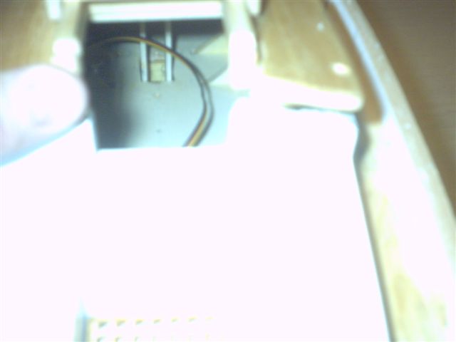
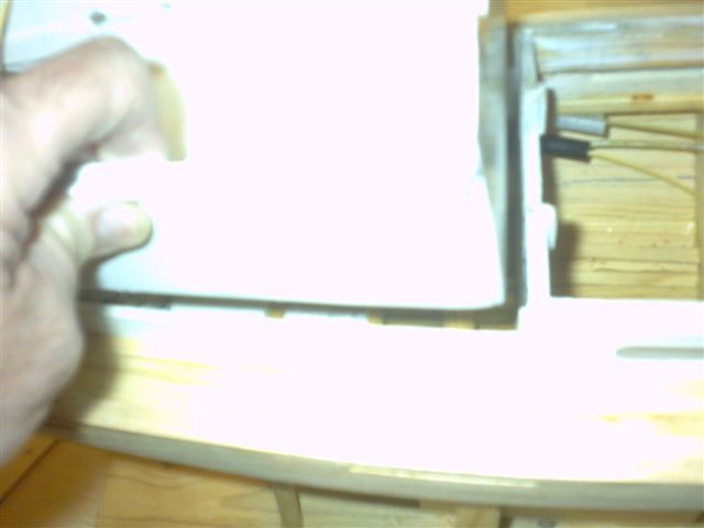
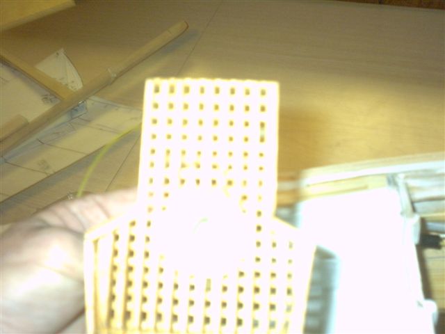
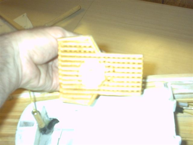
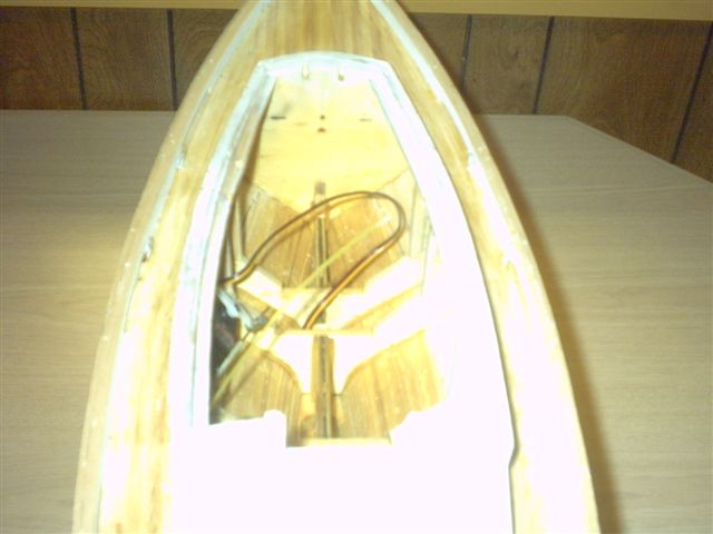
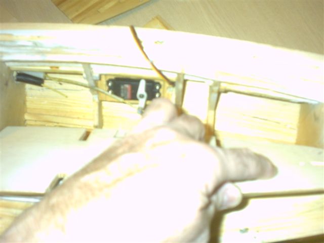
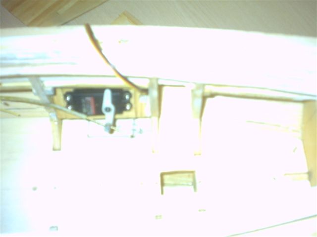
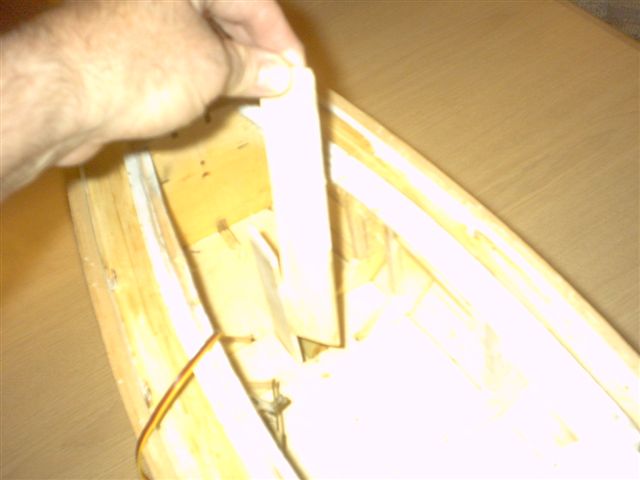
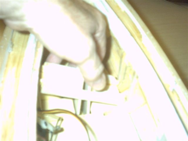
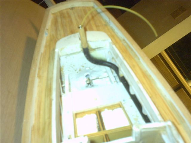
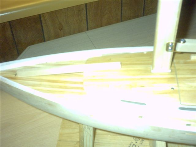
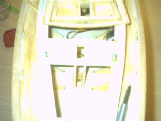
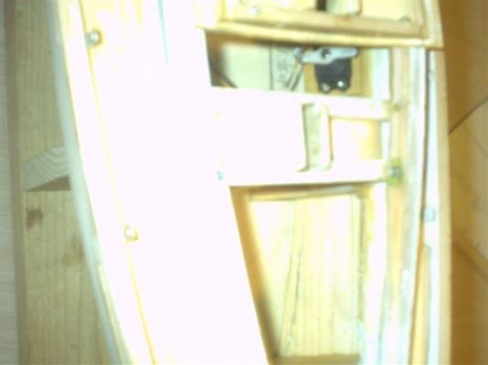
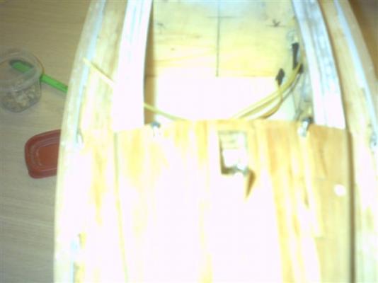
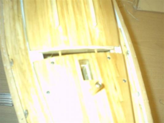
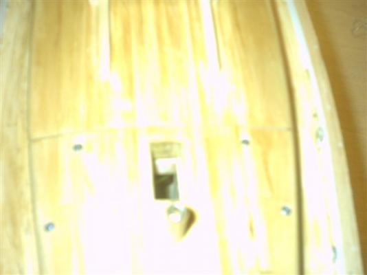
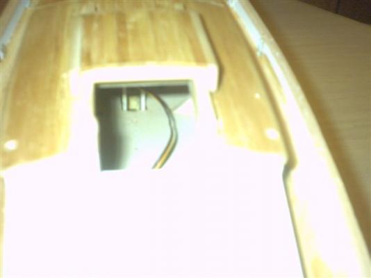
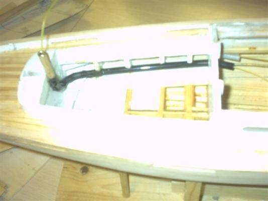
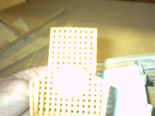
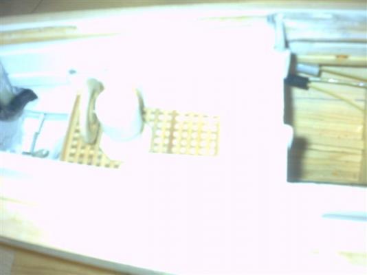
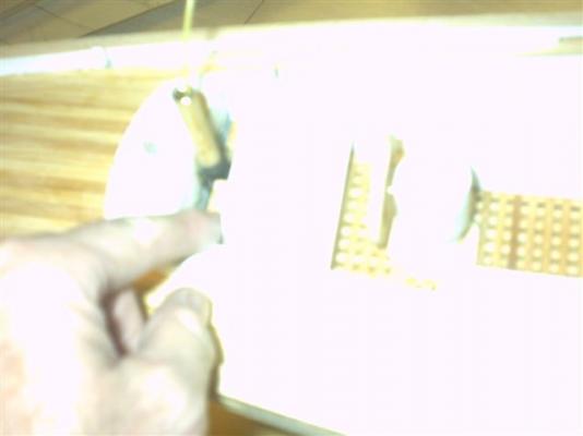
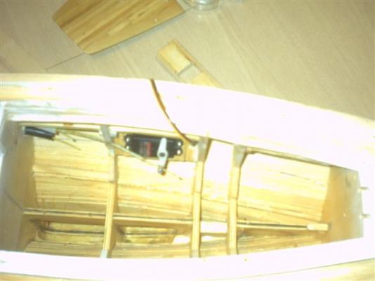
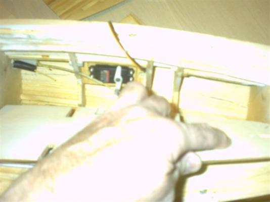
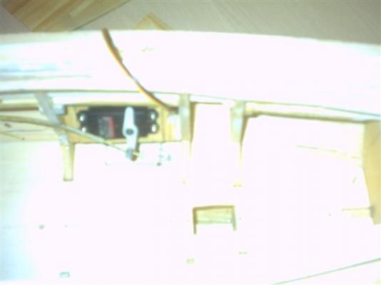
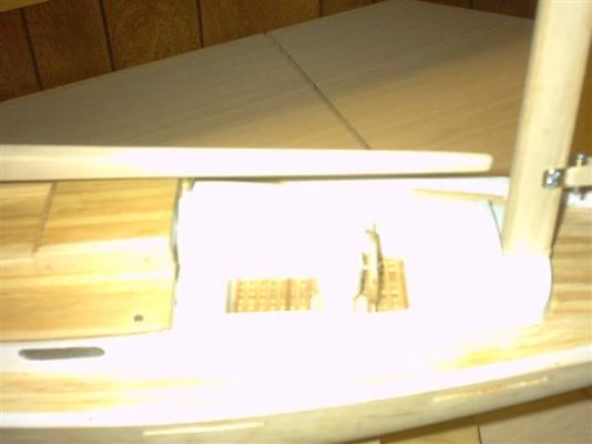
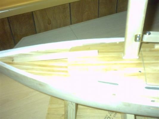
Here are the promised pictures of the most recent developments. Assembling the components of the Boat Part 1 The black tube is the channel for the main mast control line to feed up to the boom. This next picture is the start of putting the cock pit down into place. This one is the cockpit seated into place. This one is a closeup of the recessed grooves allowing the water entering the grate to channel to the sump Preparing to slip the grating down onto the sloped floor. The grating is down. Note that the hand grips are gone off the wheel. With the running line for the boom feeding right over it, I decided to eliminate the potential hangups. The sump under where the seat will set. It is also the rudder well. The front of the seat slips right behind the grating, and the seat lays back against the boom channel upright. The seat is in place. The open cabin showing the roof off and the floor is out. Showing the rudder mount inside the hull planking between the two bulkheads. Note the deep well into the keel where the weight will be distributed for best balance. Also notice the top of the mast foot between the two close bulkheads. The floor being fitted in below the rudder servo. Here I am using my finger to center the mast hole of the floor so it can set down on it's guide pins. The floor is in place. Installing the mast guides: The toe of each one is on each side of the mast foot. The shape of the v in the keel and the angled aft shape of the mast guides keeps them close in to the mast foot. The floor also keeps them tight up against the mast foot. There is a recess in the upper Mast collar to ensure that they can stay in place once the mast is in. They also lock the upper mast collar against the underside of the cabin frame. Installing the upper mast bracing collar. Note the guide ends on the collar at each end. Slipped in at an angle, with the collar guides between each set of bulkheads. Raise one end up toward the top, and make sure both ends are between the bulkheads. Raising it up against the top cabin framework until the guides come up against the top. Before the next step the screws are screwed down through the top of the cabin frame into the foreward side of the mast collar allignment guides. This will be shown in the next posting.


- 208 replies
-
- 2
-
-
- meridea
- repair ship
- (and 1 more)
-
Thanks for the responses, Popeye, and Bob. I did get the boat ballast approximately set, but now have the ingots set aside for use later. I had to scrape all that glass coating off the hull. It was not quite hard set on the outside, but it was gummy underneath. I put down cardboard under the chair out about 4' on two sides. I got it all scraped down about 5:30pm. It took about 3 hours, and a lot of vacuuming when I was done. I'm going to run over it with the orbital sander to smooth it out a bit before I re-glass it probably tomorrow if it is warm enough. I'd prefer it to be above 65 degrees F when I do the glass, because that was what we tried to have back then in the navy (we had steam heat in the shops during the winter). It was only 57 the other day when I put it on, even though the minimum was listed as 50F, and I am not sure what to expect on how much hardener it takes for this brand of resin. At least now I have an idea of how little I should not use. I think that for tonight I might reassemble it and take some pictures of it. I'll see if I can get them up sometime tonight. Walt Biles
-
This afternoon, I cleared off all unnecessary assemblies off the boat hull and tried putting on the first clear coat of fiberglass resin on the hull. I found however that the amount of activator it took to fully activate the resin was less than the commercial stuff I used in the navy. I used 4 drops in a small amount on a paper plate, and by the time I had all that worked onto the hull, it still had not started gelling. The second mix I put about twice as much into it for the same amount. Then I went back over the original and re-worked it all over with some of the new batch using the brush to mix it into the old stuff. I think it is partly the temperature, but also the activator is not so concentrated. I used to use 3 drops in a third of a 6 oz paper cup, and I was lucky to get it all on before I finished working it. I remember in the wintery months it took 7 drops. So I think it is one or the other of those two causes. I just hope this stuff sets fully by tomorrow. If it does, I may ballast the boat, and then set it out in a container until I can finish the glass job. I will need to sand this coat smooth and add another gel coat or two before I can prime and paint. Then I can get started with finishing up the rigging and sails and radio control servos. Walter Biles
-
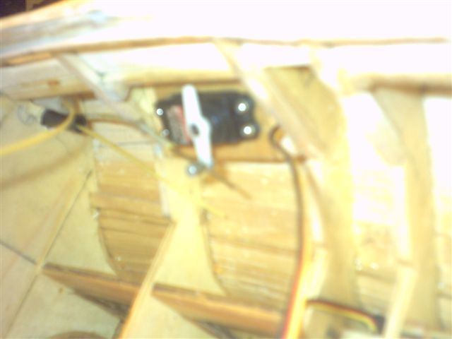
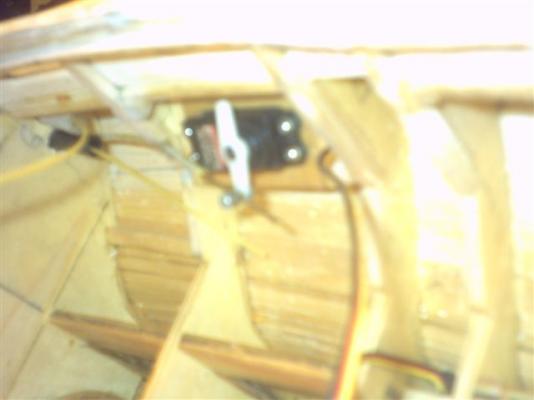
Yesterday I worked on getting the port side drive cable working on the servo. I then created a mounting for the servo and mounted it on the inside of the hull at such an angle that it would best follow the cable jacket with the arm. Then I tested it out, and it works. I cut off the cable jacket on the Starboard side. I will have to do the rest of the sealing of bulkheads after I get ballasted. Then the cockpit can be sealed up to the frames. I have started making the posterboard patterns for the sails. I am not sure which way the cloths run through the sails. I would like to seam it in the right way. I have picked up some from a video on the How To site. The videos do not run sequentially from layout to cutting to sewing to finishing. It confused the dickens out of me. I picked up some about shaping the airfoil of the sail, but am still not sure about it. I wish I could get a good progressive written with pictures of the procedure somewhere. Anyway I have begun to work on the patterns. It may be some time before I get them fully figured out. I once had to cut out and smooth a bunch of battens for a set of sails, but I did not pay close enough attention to the sail cloth layout while I was up in the sail loft, and knew nothing about shaping the sail. I only learned about how they insert the battens and lock them in with a folded overlap to help the Roach to stand straight. If I can finally get a good handle on the layout and shaping the curve to the sail, I think I will enjoy building those sails. Then comes the rigging, and ultimately getting the winch set up correctly. That will be some trial and error, I am sure. I will be trying to get some pictures as I go. I get so busy, I kind of forget. Sorry. Anyway, pictures to follow as I can. Walt Biles

- 208 replies
-
- 2
-
-
- meridea
- repair ship
- (and 1 more)
-
Well, I have dug around trying to find my old radios to see if any of them had any chance of being a test unit to work the bugs out as I installed my sail controls. It appears that the winch servo will turn about 3.6 turns without using the trim, and almost 4 with it. I am going to put 3 full wraps around each part of the spool out around a loop of the cabin. By using 4 permanent pulleys, one with a tension spring on it, I should be able to get almost enough for a full run for the main boom, and I may work a pulley reduction or a separate servo with a sail arm to work them. Then I only need to work out the stiffness in the rudder control. I am going to have to get a smoother travel from the cabin to the rudder. I think the turn entering the rudder well is too tight for an enclosed sleeve and cable. I may try running heavy fishing line or use a 90 degree L to change the direction to the rudder. I had old goldberg cables thru a plastic tube but that is too resistant in the curve I would have to use. I even tried greasing the cable and sleeve. It was only a little better. Not enough for a regular servo to run it IMHO. I ran accross my glass cloth while searching, so I can soon do the seal coat on the hull, and start glassing the hull. I have a little contouring for the top of the rudder to check out for smoother water flow. I have an order in for some turnbuckles for the guy lines to the masts (I know there is a more correct term for those, but it escapes me, Stays? came to mind later.) , and some more miscellanious parts I will need for doing the rigging, like sheaves, so I can make some working pulleys. I already have some brass stock for them, and some brass rod for riviting them into the brackets. I wish they would have given the diameter of the center hole, but the outer diameter should be just right. I should be able to work that out. That is all the news from the Meridea shipyard. Walter Biles
- 208 replies
-
- 1
-
-
- meridea
- repair ship
- (and 1 more)
-
Sherry, Great job. Are you planning to mast and rig it? With or without sails? I am wondering what can be next to see. Lovely work!! Walt Biles
-
I just spent the night re-making the mast hardware for the booms, and re-doing the after riser tube for the mizzen boom. I decided that since I have two sails with a foot that is a multiple of 7", that I would extend the aft boom so I can attach the line at the 7" mark also. I removed the up riser, and took it out the back and put another riser at 7 1/2" out from the mast. I think that if I can get the loop from the winch to go 7" movement, the jib and mizzen can work direct attached to the loop, and if I attach a pulley to the loop for the main, I can get double the travel by running the lead through the pulley, and to an anchor point on the middle bulkhead. I believe that would give me the 14" of travel for the main boom. Does that sound right? Walt Biles
-
My plans for now are to see if I can get some batteries for my old radio, and use it to set up and test the controls until I can get a new 2.4 Ghz system eventually. Walt Biles
-
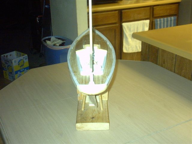
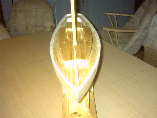
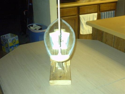
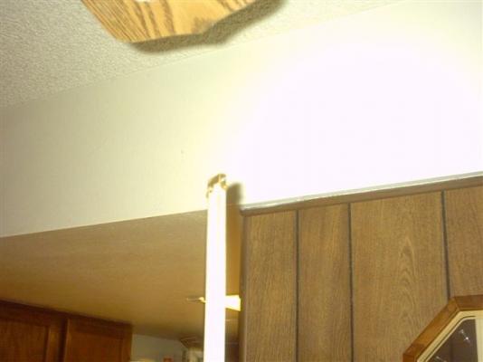
Here are the most recent pictures of Meridea. I used epoxy to completely seal the drain sump and around the drain outlet. I finished the doubleplanking of the hull and sanded it to almost smooth. I will leave it this way until just before I am ready with the glass coating of the hull. Then the hull can be painted. Once that is accomplished, I can ballast the boat, and prepare it for finishing the rigging. I now have the insides of the rails painted, and the cockpit painted. The deck and cabin roof has been primed and sprayed with clear coat (non-glossy) I have some brass cut for the main mast boom, and the mizzen boom, and the cap for the mast having 4 eyelets for the guy attachments. When I did these, I only could find my thinner brass but I found it too flexible, so I aim to re-make it all from the thicker sheet which turned up later. Full side view. Aft view. Mast cap with attaching rings Cockpit view Fwd deck view showing jib boom to be attached after guy lines attached. Front view I'm sorry about the white being too overexposed. My camera has no adjustment for brightness built in.


- 208 replies
-
- 3
-
-
- meridea
- repair ship
- (and 1 more)
-
Steve, You are so welcome. And WELCOME to the site. Walter Biles
-
Steve, If you look just above there will be a large blue band saying MODEL SHIP WORLD 2.0. Just to the right of that is M.S.W. Site & Article Downloads. If you click on that, you should be able to scroll down 3 rows to Rigging and Sails. Then scroll down and there is a PDF called: Rigging and Forming Sails for Your Model by John Tilly. There is a description and drawing of the parts of a sail. Down within the text are plenty of additional links where you can probably find lots of information. Also, on the light blue Model Ship World banner if you click on that and scroll down about 3 sections there is a section in Tips, Techniques & Research with a section on Masting Rrigging and Sails where you may find some good stuff. Good luck on your sail making. I'm sure others probably will catch up to you eventually for more help.
-
Well, it's time for some update. I put the drain into the cockpit. I have finally finished all the planking. I have been working on ways of locking down the assemblies while trying to waterproof the openings as much as possible. I am about ready to get the sealer coat on the hull in preparation for painting. After that it is trying to rig the booms and rigging. Pictures as available. Walter Biles
- 208 replies
-
- 1
-
-
- meridea
- repair ship
- (and 1 more)
-
S.os It looks pretty nice. I wish I hadn't lost my Blue Jacket's Manual. Seems to me there were diagrams of most everything in knots and splicing. Blasted shed leaked down through my whole seabag and a stack of text books I was keeping and turned it all to black mush. I used to be fairly good at splicing, although I did not use it much after A school. I'd been thinking of trying my hand at using splicing on my meridea running lines. I don't know if I can remember without my book for a refresher. I guess I can find some sort of references on the internet. Was it 6 times the diameter of the line that the splice was supposed to go from it's start? or was it 6 times the diameter of the spliced part of the line? Walt Biles
-
Ed, Thanks for your response, I respect that rule too. I was mainly trying to think if the outer surface had a taper into the thinner planking or did it step down from the thicker planks to the thinner ones at each edge. I believe that from about the deckline to over the bulge of the hull probably added greater strength against hogging and bowing of the hull. I haven't seen much picturing of clippers, but had an impression of smooth outer surface going downward. Walt