Walter Biles
-
Posts
356 -
Joined
-
Last visited
Content Type
Profiles
Forums
Gallery
Events
Everything posted by Walter Biles
-
 When I was in the navy, I got sensitive to fiberglass activator. I had been doing fiberglass repairs to their boats for about 9 months. I began to have a prickly sensation everytime around my nose, and in the hair on the back of my neck and around my ears which originally I attributed to the glass particles I sanded out of the boat. After several months more I began noticing that every time I opened the activator bottle to activate some resin, I would get hit with those symptoms immediately. It felt like my hair became prickly. Eventually I mentioned it to my chief petty officer in charge of my shop. One day not long after, another chief and the tool room attendant had me involved in conversation in the tool room and the chief was working in his office on the other side of a partition. I began feeling that irritation, and started scratching my hair and blowing my nose, and out walks the chief with a bottle of activator he was closing. He decided to check me out. By then my eyes were itching, and I was beginning to esperience nasal congestion. He took me out of the building for some fresh air. It was then that we moved all fiberglass work outside. He put me in a supervisory capacity and had me try to teach the skill to 9 other people. He put me on rubber gloves when I handled any of the stuff, and a respirator around the training. I soon got a change of assignment within the department. Epoxy has never affected me that way, yet, so I just steer clear of fiberglassing. I too am not very comfortable when I use any CA. It is a little too close to the earlier experience for me. I favor safety precautions. Walter Biles
 -
I appreciate that, but was more looking what sort of store in Prc. might carry it. I think I got mine as part of an auto body repair kit. Since that was in the '70s I am not sure if they would even use that anymore. I guess I could try the internet. I tend to forget about that. Walt
-
Thank you, Michael and Bob. I finished the first planking behind the rudder to the transom and that finished up all my 1/8" basswood for now. I have an order for more put in, but I am not sure how long it will be. I went ahead and rubbed in yellow glue into the planking up to where I have done, to seal and harden the wood a bit. I also rubbed it into all seams real well, to help bond and seal them together. Then I sanded it down to a relative smooth, and I started the second level of 1/16th" planking around the keel bulb, and began working that up. I have the first layer almost to the waterline, and am cutting all those pieces to fit around the multicurves on the keel. I have the first two strakes up from the bottom of the keel. I am going to wide plank around the flat faces of the keel, until I get into that inner curve. Bob, do you know where I might be able to find some light fiberglass fabric, not too thin. I haven't found that couple of square yards that I used to have. I got stupid when I thought I might never be able to do anything anymore, mind-wise, and I may have tossed it like I did a lot of my things when I moved in 1996. I believe I will use 30 minute epoxy and glass the whole body of the boat after I get it all smoothed out and ballasted. I am going to use the first coating of epoxy as a sealer while I ballast, and then start adding one of those self draining sumps for the cockpit like they had on the real thing. I found out what I can use for the rudder arm. It would be like the ones I used on the front nose wheel steering arm on my planes. I may even have one somewhere. I've been building all night, so I am signing off for now. Walter Biles
-
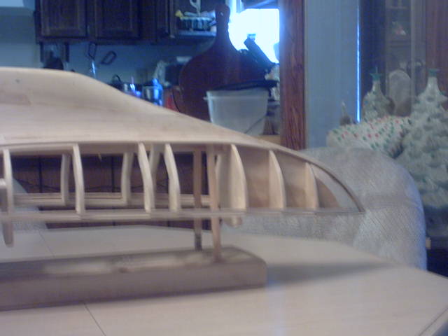
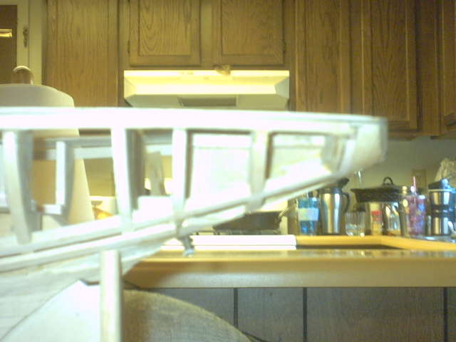
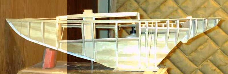
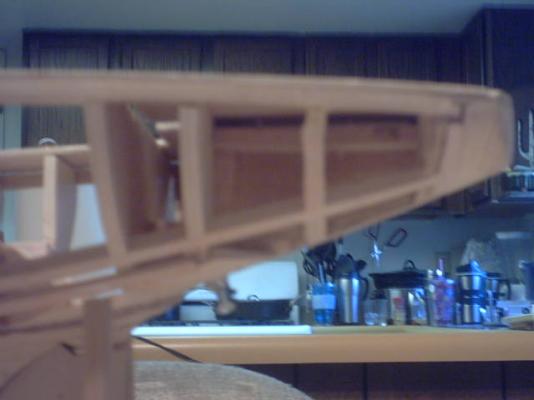
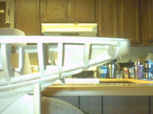
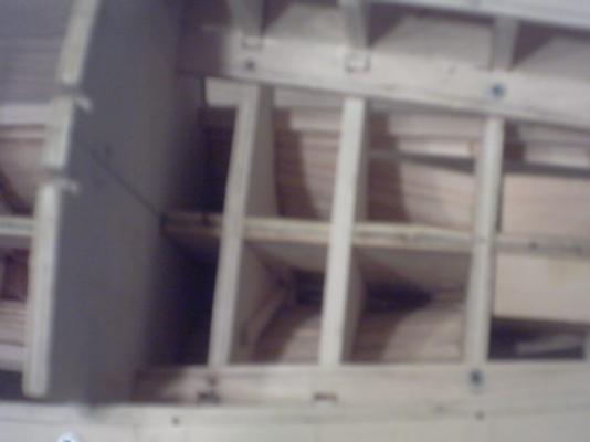
Meridea Pix Part 3 This is a fair shot of the stringers added to strengthen around the rudder pivot where it sagged. Fair shot of fwd hull showing keel block and some planking. This one showing the 4 stringers for strengthening. Two along deckline, and two on either side of keel running to transom block. Also along the keel you can see the shaping block around the rudder area. The long planks coming from the planking nearer the keel will be a division of planking onto the bottom of the s t e r n. The sides will continue up from there to the deck. The stringers will all be covered up. Walter Biles


- 208 replies
-
- 1
-

-
- meridea
- repair ship
- (and 1 more)
-
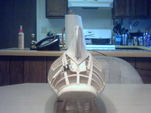
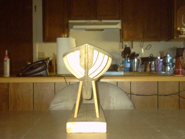
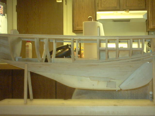
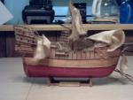
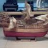
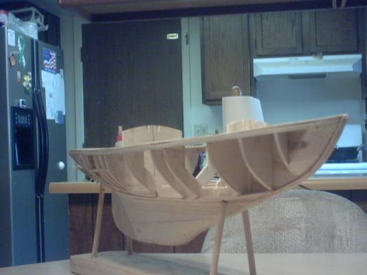
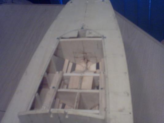
Meridea Latest Pix Part 2 Picture from Bow on. S t e r n picture. This and next picture trying to show gap below the deck from the break at the rudder causing keel to sag. The top of the keel used to be against the deck. I shimmed the bulkheads up until they met the deck again. Then I trimmed the extra off the bottom of the keel where the bottom should be. The better of shot of port showing planking so far. Note: the filler blocks on the side of the keel block. The termites I hired to hollow out the ballast spaces got a bit carried away. After the fill pieces, I epoxied the inside of the hollows to build them back in to thickness.


- 208 replies
-
- 1
-
-
- meridea
- repair ship
- (and 1 more)
-
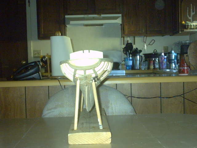
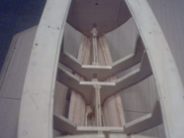
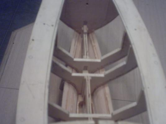
These are my latest pictures of Meridea. Part 1 Aft balast spaces in keel. Fwd balast spaces in keel. Looking down into cockpit/rudder area. Looking fwd into cabin area of hull. Port side view. Stbd side view. Flash lit aft balast area. Flash lit fwd balast area. Fairly good port side view


- 208 replies
-
- 1
-
-
- meridea
- repair ship
- (and 1 more)
-
Thank you, Michael. Walt Biles
-
Thanks Popeye, This frame will be the 6th one, the first 3 in cardboard, and the last 3 in wood, but it is finally coming out the way I wanted. I will have an obvious mistake on the inside, but it will show a correction to it, and the boat should work. It is the closest I have come to a fair frame yet. I think I can proceed with this one, finally. Now I need to get pictures to post. Walt Biles
-
BOAT BUILDING Why am I doing this boat I used to build model airplanes so I could see them fly. I liked anything I built to do what it was supposed to do, and me there to get to see it. Sometimes I built something to fulfill a need. Building a set of Roman war weapons that you could demonstrate how they worked for an ancient history class. I had to quit building models of airplanes, because when I tried to fly, I kept breaking them, because I could not keep my mind out in front of that plane as an RC craft, and I reached a problem with solving how to fix them so much. I finally realized my mind wasn't working the way it used to any more. Then I found out why. Sleep apnea destroyed my mental links. Now that I am becoming better from being treated, I am now doing this hobby as therapy for my mind. I am finding that if I can set down from a problem and imagine how I might do something with it, that eventually I can still find a resolution. In the end, since I am building an RC sailboat, I can play with it and see it do what it should do. I could never hope to do that with RC airplanes now, but boats are much slower, and only work on 1 plane surface of water. Now I hope to have my boat and play with it, too. I'm still a kid at heart, but I have found out that I can work on this boat at my pace, and I now have the patience and the hope of being able to complete it one day. Now my enjoyment is in the building, and I have the patience to wait for the further fulfillment of some day getting to see if I can sail it. Since it will be much slower, I may even be able to enjoy that, too. If I can, then I will eventually build something more, and that means I am achieving my goal of overcoming personal obstacles. If I can still build, I'm alive and I am not defeated. Walt Biles
-
Hi Popeye, The boat is coming along alright now. I got the deck frame hanging at the right level now, and have started permanent installation of the bulkheads now. I am working on just where I can add some stringers along the sides of the hull, so my rudder mechanism can operate freely. They will help carry the strain on the keel where the rudder pivot bushing went through. The blocking I did was successful for the time and purpose, But I was a bit upset, when I found the parts had shifted within the epoxy. Now that I slipped the aft bulkheads up in their slots, and shimmed them there, they are glued in place. I am trying to find just the right place in the sides of the hull where a reinforcing stringer will work out. I believe I will try to put it in the round bulge above the rudder on both sides. That way the arm can swing clear of it, and it should help keep the frame from further problems. I am also putting a stringer all along just under the deck. That will help my deckline remain true and add to the bracing to prevent another break after I sand the keel blocking down around the rudder area. Due to the shape of the hull and it was originally done in fiberglass in the real boat, the usual framework of a POB hull meets with some complications that just weren't an issue in a fiberglass hull. I am trying to simulate that hull support with the additional stringers. If I inset them into the bulkheads just below the cockpit deckline, then they can run along the side of the bulge back into the stern of the boat. If it works out well, I will change my plans to match. I think things are going to work out fine now. I have the hull faired out fairly well now, and have started thinking about the first layer of planking. On this big of a boat(34.2"), I believe I am going to try 1/8" x 1/4" basswood planking on the first layer, and try to do an overlap of the joints on the second layer. I want a sturdy hull. I may drop it or something, and I don't want to have to repair that part. The masts and cabin will be enough to work on in that instance. I considered glassing it after, but am not sure if my allergy to fiberglass activator will let me do that, although epoxy could be an alternative. I would have to find some of the older slow stuff so I would have time to work it properly, and I am not sure if it would work the same as the glass resin. I did enough of that in the navy to know how it would work, but I never really tried it with epoxy. Thanks for checking in Popeye. Walt Biles
-
Thank you Bob, I was shocked when I found it, but I just studied it and it seemed that if those bulkheads could be shimmed up, I could get it mostly back. Other than the one for the transom I had glued, and the potential of the mizzen mis-alignment, I thought it might be okay. I just pondered it for a day, and slept on it. By the next day all the alternatives just did not seem to be any good. Also, I figured out what I could have done that might have prevented it. The only problem was I had cut up my plan with the material when I cut out the parts. One of those "I could have had a V8" moments. Walt Biles
-
Thank you Michael, I have been working on it since my last post, and actually it went fairly well. I now have all formers but 3 glued in place starting from the bow. I am going to reinforce the hull in the area around the rudder before working the blocking down. In fact I plan on putting 2 stringers inset into the bulkheads to help bridge the weak area. That way it should take some of the stress off it, while I work the blocks down to about fair. I knew from the start that the rudder was a potential weak point, but by putting in the stringers to hold the spacing and putting on a few rows of planking at the top, I think it should hold up until I can get it all planked. The deck alignment is now back on track. Since the whole thing was originally done in fiberglass buildup, they wouldn't have had any such weak point because the whole hull was part of the structure. That was what got me to thinking about adding stringers to support. There is just too much multicurvature in the area of the rudder for a reliable frame. Therefore, I figured improve the shell strength, maybe I can get it to stay together while I work on it. Walt Biles
-
Well, stuff happens. Sorry, I don't have any pictures of my recent work yet. I had all the new bulkheads cut to shape, fitted, and at the last pre-assembly of my hull held by trenails and small screws, everything fit very well. I decided before I started glueing all of it together, I had better put in the rudder sleeve tubing into the frame, and reinforce it before I start to glue all into place. I got the sleeve in place, and cut the 3/4" shaping blocks to go on either side of it, and made the recess for the rudder arm to travel. I SHOULD HAVE HAD THE KEEL LAID OUT OVER THE PLAN WITH WAX PAPER TO PROTECT IT FROM GLUE DROPS AND ONLY APPLIED THE TOP BLOCK TO SET FIRST. I went to epoxy the blocks around the weak spot created by the tubing going through the keel former, and clamped the blocks in place. Nothing looked amiss. However on my re-assembly of the hull parts, the foreward part of the deck once screwed down foreward, no longer met the aft frame deck. the keel frame had sagged within the glue until the aft keel now rides at 1/4" below the deck. I have put the whole project on delay, until I figure out the best way to resolve the issue. I am seriously considering putting shim blocks in the notches under each of the 3 low bulkheads, and building up the keel frame with a 1/4" wedge of filler, and re- trimming the bottom of the keel to match. I don't think the change from square on the bulkheads will be more than 1 or so degrees. The length of the deck will still be right, and I can shift the angle of the two bulkheads foreward enough to keep the mizzen vertical. I just don't have the materials anymore to make a whole new keel and re- install a new rudder pivot. The rudder shaft was in place when I glued the blocks on, so the shaft line is correct, so it must have pivoted right behind the rudder shaft sleeve. I think that this could be my best fix. I will have to cut away the aft former and filler block, and add it back at the end on the right elevation with appropriate bracing blocks. That was the only bulkhead that I had glued into place so far, with epoxy, of course. I have been running this fix over in my head many different ways, and this is the only way I can think of that might work. I am tool restricted or supply limited by anything else I have considered. I am going to make myself a story jig, to lay down to the top of the keel as a reference, so my allignment will be sure. I think this is the only way I can go without buying some new stock, and I have gotten too far to have to do it all over again. This must work. Walt Biles
-
Thank you Michael, Bob, and John. I had not been very satisfied with the shape of the former build. I kept finding discrepancies that I thought had been corrected. I decided to go find some of my original body plan drawings and compare them. Thank goodness I had an archive file. I think I must have been distorting the shapes with lift and drag or something. I just took copies of all of the shapes and drew new formers and scaled them directly to my current build dimensions as a whole drawing. Then I cut out new ones with the last of my plywood in that size. I had wasted a lot of it on mis-shapen drawings. Anyway, I am glad I now am close to the right shapes. I want to preserve the faired shapes to the final drawing. With that I should be able to make a boat of any scale that I may want from that plan in the future. I have learned a lot about the difficulties in design and getting it to comply with how the materials are going to work when cut to that plan. I am glad I have taken the time to go through all this. Walt Biles
-
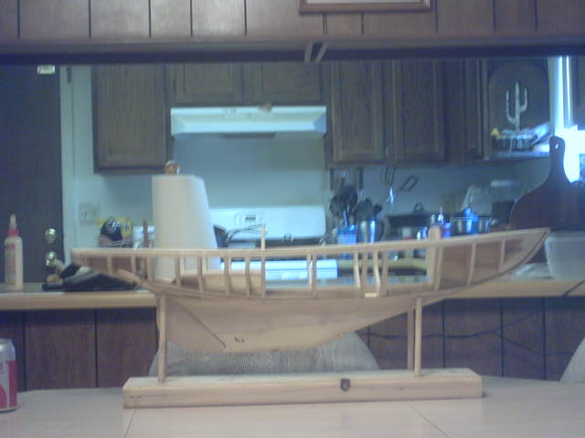
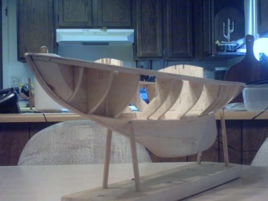
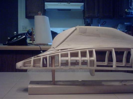
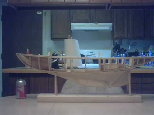
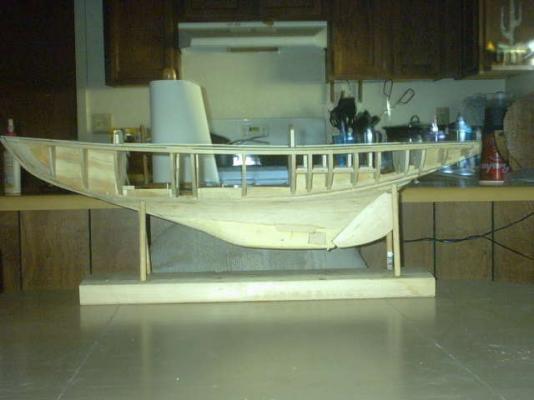
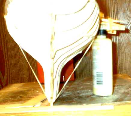
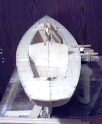
I have been hard at work lately. I have made a whole new model of Meridea. I was not satisfied with my former one, and could not correct the fairing of the hull shape sufficiently. I cut a new keel former, and re-drew the hull formers from my original body plan. I am not sure why my earlier ones had gotten mis-shaped, but every one of my previous builds would not come out the same. I had to go back to the drawing program, and re-do my plans. Here is the side view of my new boat. This next one is is a not too good picture of the fairing as seen from the aft of the boat. This is of the aft deck foreward. You can see only the foreward and aft bulkheads of the cabin, I will build the roof framework tied into them to fix the bracing of the sheath for the mast which will allow the mast to be inserted and held upright. Later I will only cut away portions of the cabin roof to provide access for controls installations. I am using a 1/4" cabin floor of plywood so I will have good screw attachment. Only the foreward part of the cabin from the mast sheath to the front of the cabin will be permanently attached. I will make screw on covers for the after parts of the cabin. I will need to have access to the keel area until the ballasting is completed. Before closing that up, I will have the inside waterproofed, and foam compartment filling to do. I only have one concern. There is not a lot of room for any rudder control arm. The placement and shape of the hull are pretty tight there. I believe I will need the space beneath the cockpit seat to have room for the arm movement, so that may be enlarged enough to make enough room. So far I have only glued two places. the mast foot filler blocks are added to the frame. I have the side of the mast sheath from the foot up through the deck cabin roof, with enough to trim to fit the roof. I am planning to add some outer deck stringers where they join the side planking due to there being attachment points in the deck at the edges for the mast stays and the hand rail stanchions. I now have the floors approximately faired into the shapes of the hull formers. Most of the formers are fairly close to being faired. I now think I have a hull frame which can now be worked into shape. So far, I have only slipped things together, and blocked or trenailed things together enough to make it where I could work any part that I needed. After seeing it to this point, I believe it is close enough to build. I will now dis-assemble it one last time and scan the final shapes of the formers into my CAD for the final adjustments. Then I can have some fun with the glueing and blocking and actually building my boat after all this time. YAY!!! Walt Biles

-
Cruizer-class Brig-Sloops of the Royal Navy
Walter Biles replied to molasses's topic in Nautical/Naval History
Dave, That is pretty interesting. I like reading about ships and what went on in them. Walt Biles -
Hi Bob, Thanks. I hope all is well with you and your wife. Walt PS: If your 'Spray' is ready, I think admin waits for a note to them to put it into the Gallery.
-
That could be it, especially if the editor icons are in a shared feature on the editor. Walt Biles
-
Now the editor is working with high colored icons again. Prior to the last message I had edited, then printed out, then saved my build to my computer with the bottom Icons. After that it went dim, and I wrote the last message. Now after being gone some hours, the icons are high color again. I don't understand every thing I thought I knew about these editors again. Oh Well!!! Walt.
-
Well, the page printed entirely with pictures. However the editor seems not to be fully functional again. It comes up at first then all the icons fade to faint after 1-2 seconds. Walt Biles
-
I have been brainstorming on the build progression: I am going to have to build both sides of the lower keel on the plan over wax paper. I will epoxy those together on a flat board. . Once I have a flat straight keel I will build the keel jig and put it all into it on the board. Due to the long multicurved shape, I am going to have to make one that will follow the curve. I will use the cut away part of the sheet for the track bottom, with pine board on each side screwed through it. I have a good 1/2" birch plywood piece big enough for a working board, and will attach the keel jig to that. I will use some 1/4" plywood for a front and back brace well squared at the front and back. I will have to cut some more upright braces for temporary use until I can get the bulkheads in with blocking of some kind below the cabin and deck floors (ALL SUBJECT to revision) Walt Biles
-
In the navy, our portable pumps were either 250 gpm or 500 gpm. It took us hours to pump all the deck level downward on an 75' boat. and we could only get those 2 into the area. However we did not have any water coming in by then. It was lifted out by a huge floating crane. I know the check valve that failed was on a 10" discharge, and the boat sank in less than an hour. By my recollection a 10" pipe will handle about 800-1000gpm. Man that rot in their hull must have been something. Walt Biles
-
Thank you Wayne, I like that drawing. It was more understandable. A ton of water/min. How big was the diameter of the lift pipe? I have been trying to figure the approximate gpm that would be. They must have had to have had more than one pump on big ships. On only a 200 ton vessel that would amount to 200 minutes of pumping. They definitely would have to have had plenty of men to swap out as they got worn out. If they got a very big leak in the hull, such as a board rotted out for a foot, it would keep them going. (I had been considering that from the Update to the Bounty sinking.) I know they would have had to have current day pumps for that by legal standards, but after the level got up to them, they wouldn't have them. I'm wondering if they had the older pumps to fall back on or were they were ornamental. Walt Biles
-
Thank you Wayne, That answers part of the question. Didn't they have to have some sort of guidance at the lower end so that the little buckets didn't get hung up going into the bottom? Also, how did they keep the bucket and the chain on the sprockets at the top from skipping when the dipper went over the driver wheel? I wonder about these things. It seems like it would have to affect how someone could model this. Walt Biles
-
I am interested in HOW do the chain pumps lift the water. The mechanism puzzles me. I understand the auger, and the rod lift into a back checked line, but what did they use to cause a lift to the water to get it up to a discharge point, and did they have an overboard discharge someplace to keep the water off the deck while in action? Walt Biles