HOLIDAY DONATION DRIVE - SUPPORT MSW - DO YOUR PART TO KEEP THIS GREAT FORUM GOING! (89 donations so far out of 49,000 members - C'mon guys!)
×


Tecko
-
Posts
336 -
Joined
-
Last visited
Content Type
Profiles
Forums
Gallery
Events
Everything posted by Tecko
-
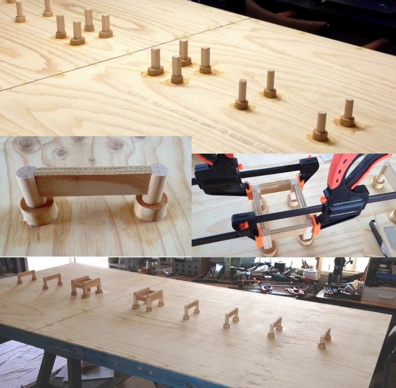
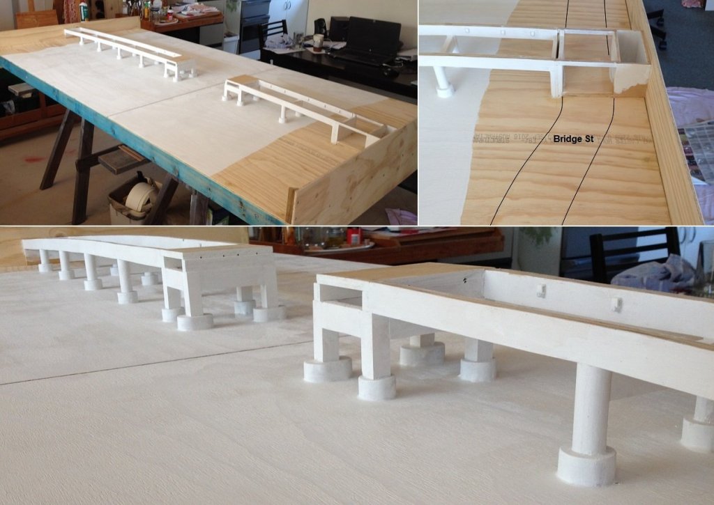
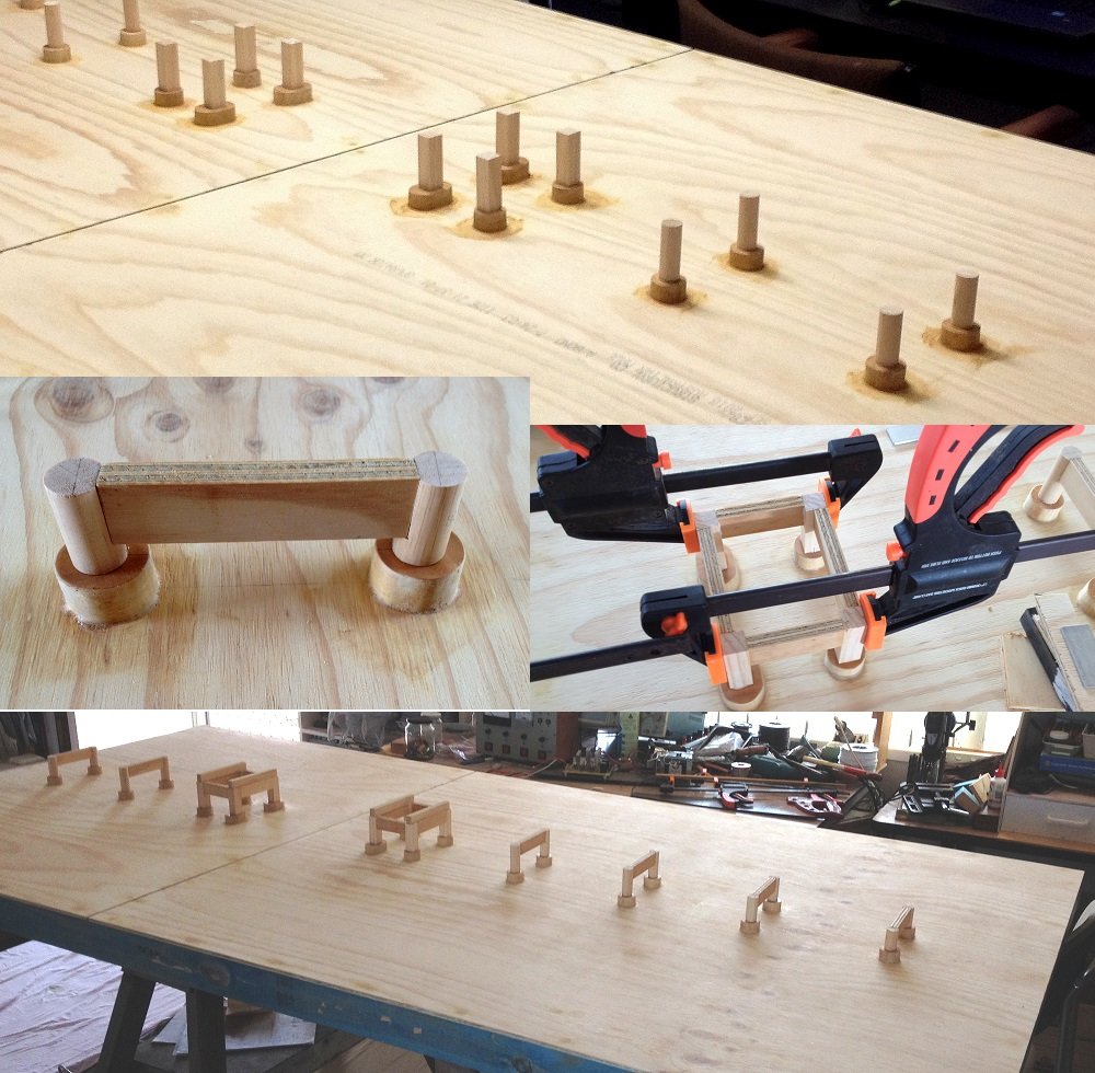
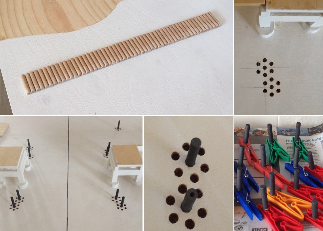
 The bridge footings. I used bamboo skewers for doweling. The footings I do not have access to a lathe, or round stock of near size. So it's just good old fashioned hard labour for a pirate (cut and file). Arg! The piers The girders And an undercoat. Above, you may notice some holes in pier ends. These are for electrical contact points for bridge span. The span will have a rechargeable battery to power its vessel traffic lights. Battery gets recharged while docked onto road base. Fender piers (aka Dolphins). The outer centre piers have a hole through them for installing the navigational lights (small 3mm LEDs). Next is some electronics
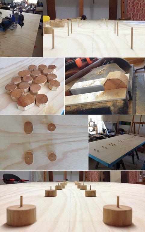


-
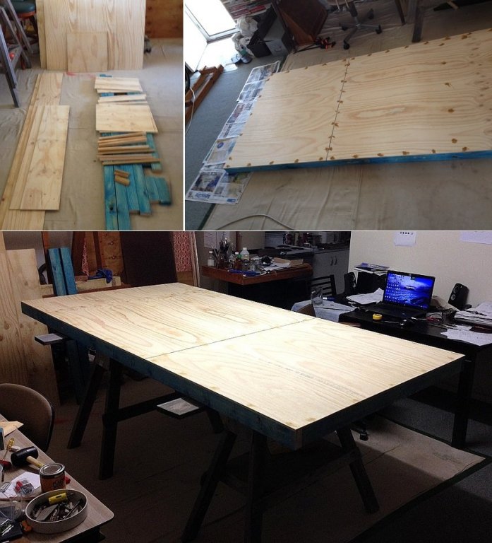
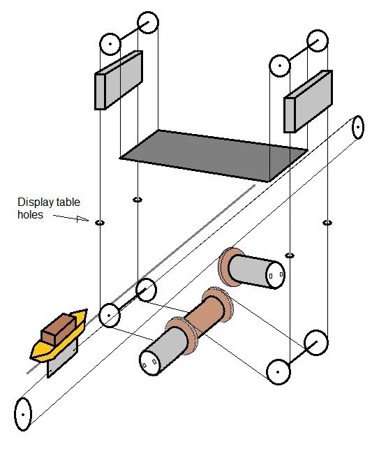
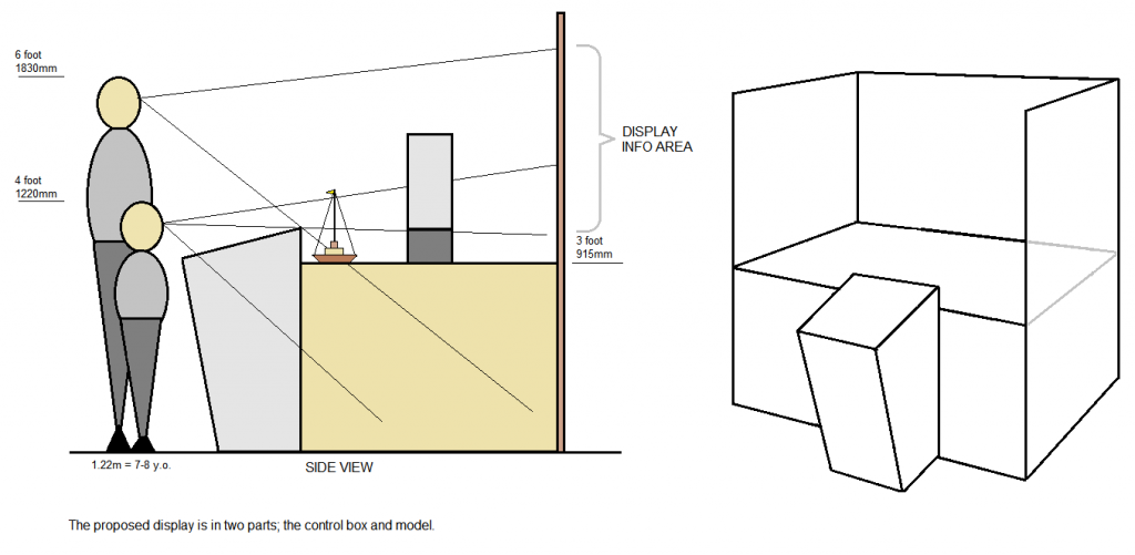
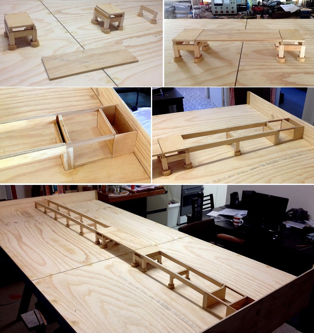
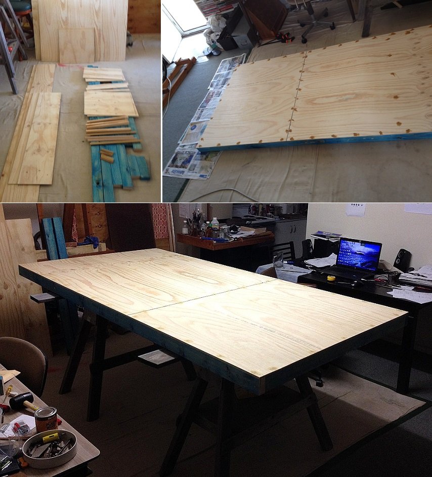
My goal is to create something like this. The boat and bridge motors will be under the display table - in a control box. Both will be moved via cable and pulleys. The tabletop. Yes, my lounge is my studio-workshop. The museum did not have enough workshop room for this display. The control box to be aligned directly under the tabletop slot for the boat pathway. It has two access doors. Next is the bridge substructure.
.thumb.jpg.ae85377514ce3823930ac3d2cdf8003b.jpg)
-
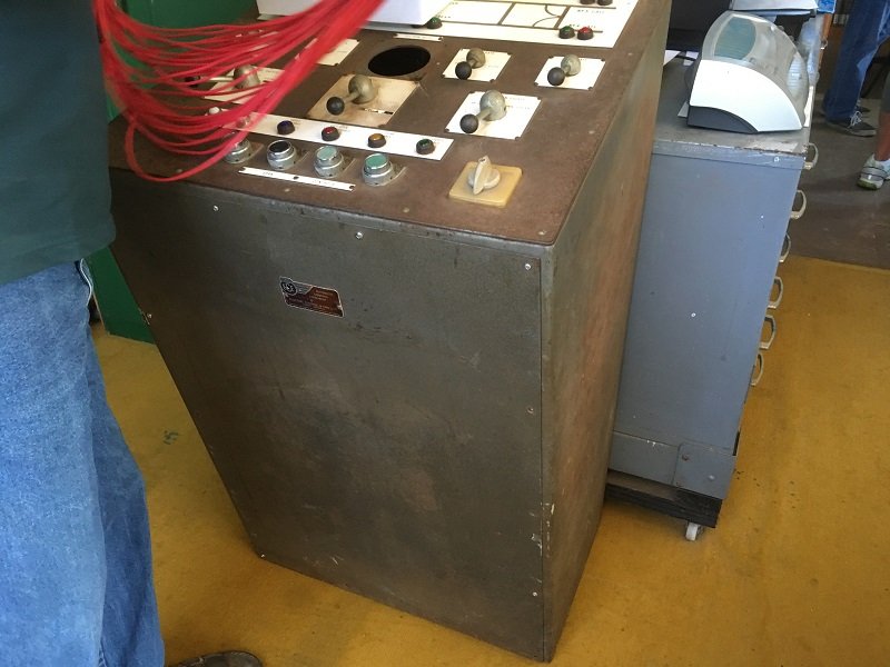
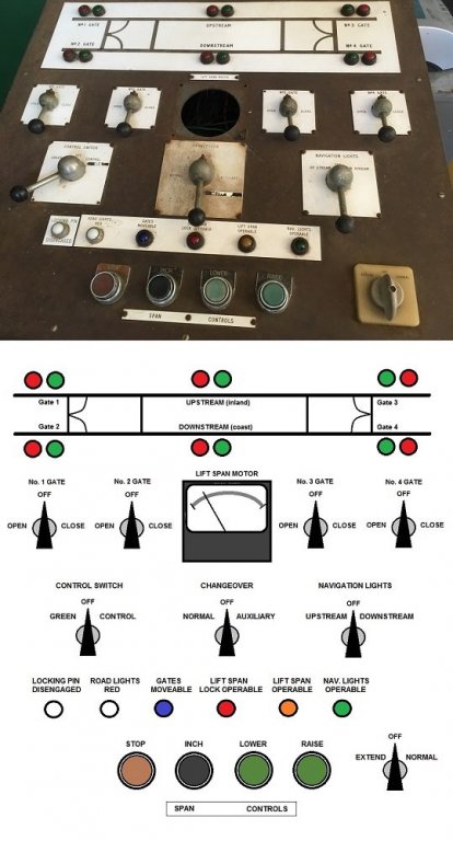
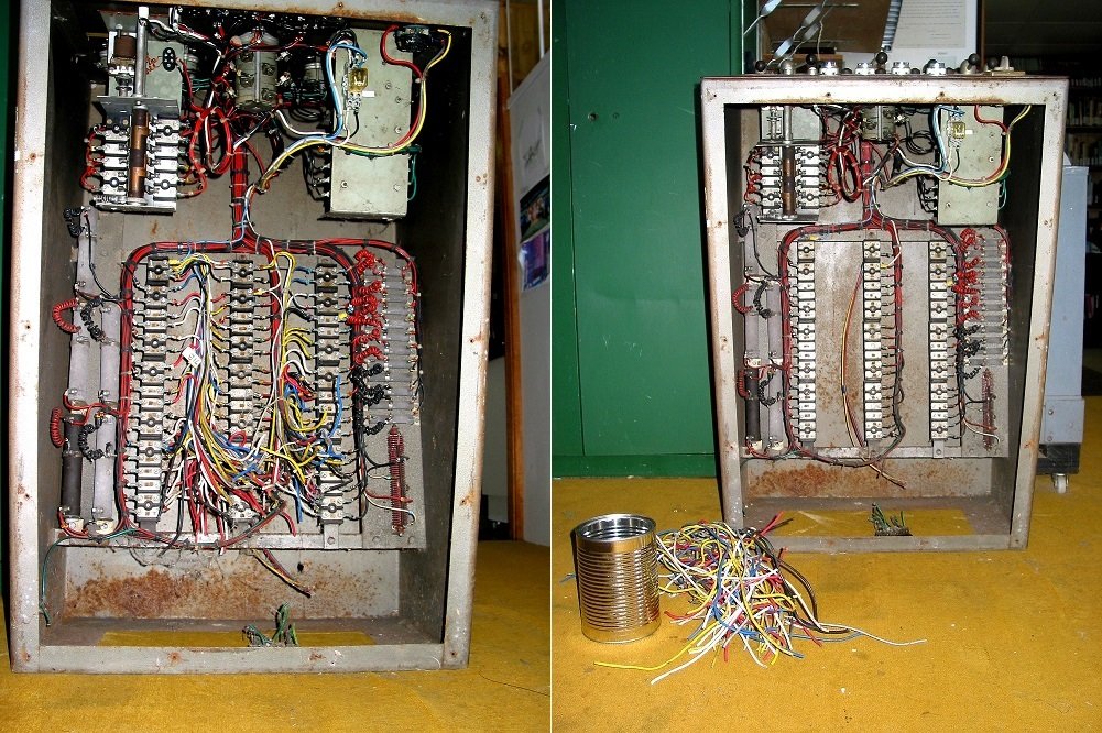
Thanks Patrick and Keith. I hope not to disappoint. To start of with, I thought it would be good to share know what is inside one of these consoles. The plan is to keep the exterior looking as is - antiquated (rust treated and satin varnished). However, the interior will be spruced up and visible through a perspex front panel. The interior will become a lit wiring diorama - an added treat for the museum visitors. Below includes a drawing of the panel layout The control panel components will be used for controlling homemade electronics for the model. However, I needed to know what each control component was used for. I soon discovered that there is a purposeful sequence of events to raising and lowering a lift-span of the bridge. For quick insight... Bridge navigational lights must be on. Vessel traffic lights for both up and down stream are red. Road traffic lights are switched over from green to flashing amber lights for a delay of 20 seconds, and can be delay longer if necessary. During this time an alarm bell is sounded. The bridge operator, in span hut, looks through an inverted periscope to check that no cars or people are between the two set of traffic lights. Traffic lights go from amber to red. Four gates close across the road. Span lock is disengaged. Span is raised all the way to the top of bridge towers. If vessel is upstream then its traffic light switches from red to green. After boat passes under bridge, both vessel traffic lights are red again. The bridge lowers about 60% of the way, then it gets inched down in four stages. The last stage is fairly close to road base. Span gets locked again. Gates are opened, Then road traffic lights turn to green. My task is not only have the control panel operate as mentioned, but to also make it childproof. In other words, a switch cannot work unless it's turn in sequence is for it to work. This is so, for example, the span cannot be lowered onto the traversing boat. This bit has not yet been fully worked out. It's a bit of a headache for this out-of-date technician. But I know I will have the logic circuitry worked out. Below, the console has been opened for examination. It was built around 1962 and those two large rotating switches are custom made for the task. I took all looses wires out to make access to wiring harness for further eaxamination. Eventually I took the whole console apart. It needed a complete rewiring. Next is the display table.
-
Amazing and beautiful work Keith. You certainly have the tools, knowledge, and skills. I have learnt, from this thread, nothing is impossible. What seems impossible is only not yet understood. Thanks for sharing this thread.
-
What a beautiful ship. I am in awe of it. Does she need a captain?
-
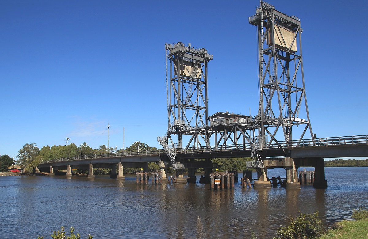
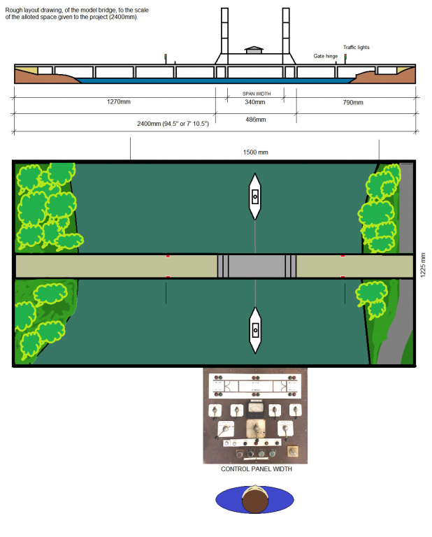
To be honest, the boat in this diorama will be built near the end of the project. The diorama is going to be a working lift-span bridge with a boat traversing underneath it. The bridge fits on a 2.4 x 1.2 m (8 x 4 ft) tabletop. The scale is 1/72. There are no available plans for the bridge. Created my own plans from photographs and two diagonal reference measurements (road width and span length). An antiquated control console of the actual bridge will be converted to operate the model. Created my own electronics for the diorama. I am a volunteer for the Ballina Naval & Maritime Museum. They are funding the material costs. The diorama will be an interactive display for the museum. This is my second model I have ever built. The first was done 26 years ago. It was a 1/10 scale working Tesla coil used in Colorado Springs in 1899. The current model is halfway to completion. My task is not to make an exact reproduction, but a close simile. Available materials limit the accuracy, but I endeavour to do what I can. The boat is not following any plan other than my own. It has to look symmetrical because the boat only travels along a straight line under the bridge forward and back. Seventy percent of the project will not be directly related to the boat. I have considered the Shore Leave forum but felt that it would get in the way of all those fun threads and other non-modelling topics. So I hope you all don't mind me being here. The model is based on this bridge located at Wardell, NSW, Australia. The display area for the diorama will be something like this.. There are quite a few photographs to upload - to catch up to where I am currently at. When I do catch up I'll let you know in the post. to be continued.

-
Thanks Eddie for info.
-
I have not built a boat/ship yet, but plan to build a scratch build one for a diorama that I am working on now. The boat will need to be symmetrical in appearance. That is, not knowing which is bow or stern. Reason? The boat will traverse, upstream and downstream, under a lift-span bridge. I don't want the boat look like it is travelling astern under the bridge. Can I include this diorama, bridge and boat, into this build log thread?


.jpg.c0c827931007f283d0159f8ae1f57fa6.jpg)