HOLIDAY DONATION DRIVE - SUPPORT MSW - DO YOUR PART TO KEEP THIS GREAT FORUM GOING! (Only 53 donations so far out of 49,000 members - C'mon guys!)
×

Peter G
-
Posts
39 -
Joined
-
Last visited
Content Type
Profiles
Forums
Gallery
Events
Everything posted by Peter G
-
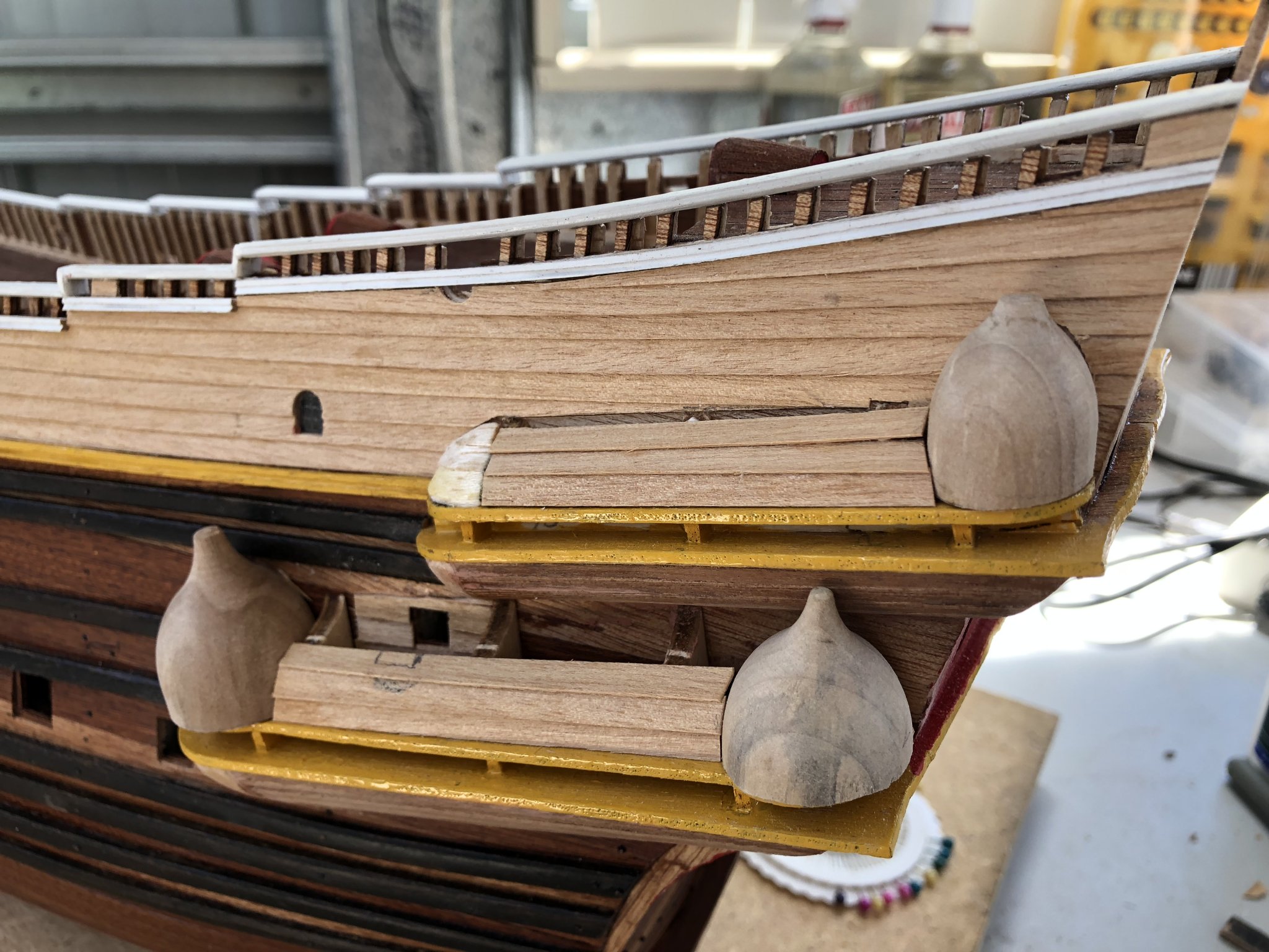
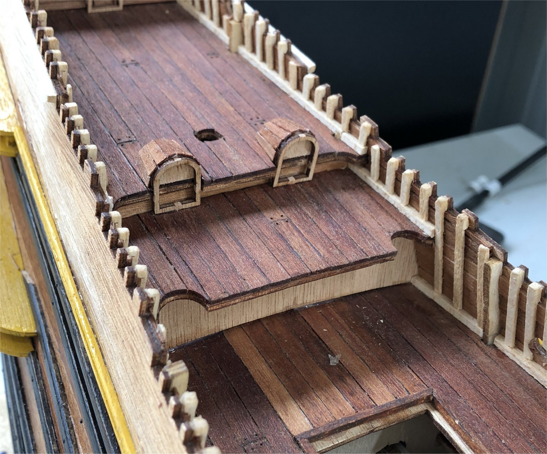
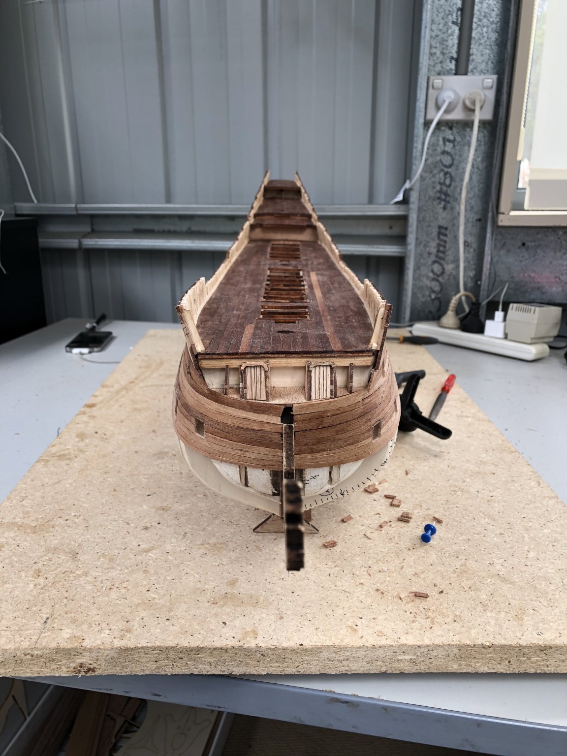
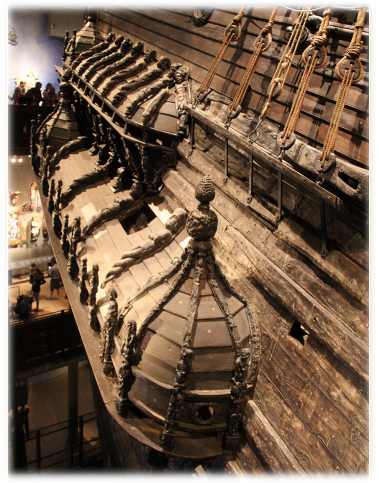
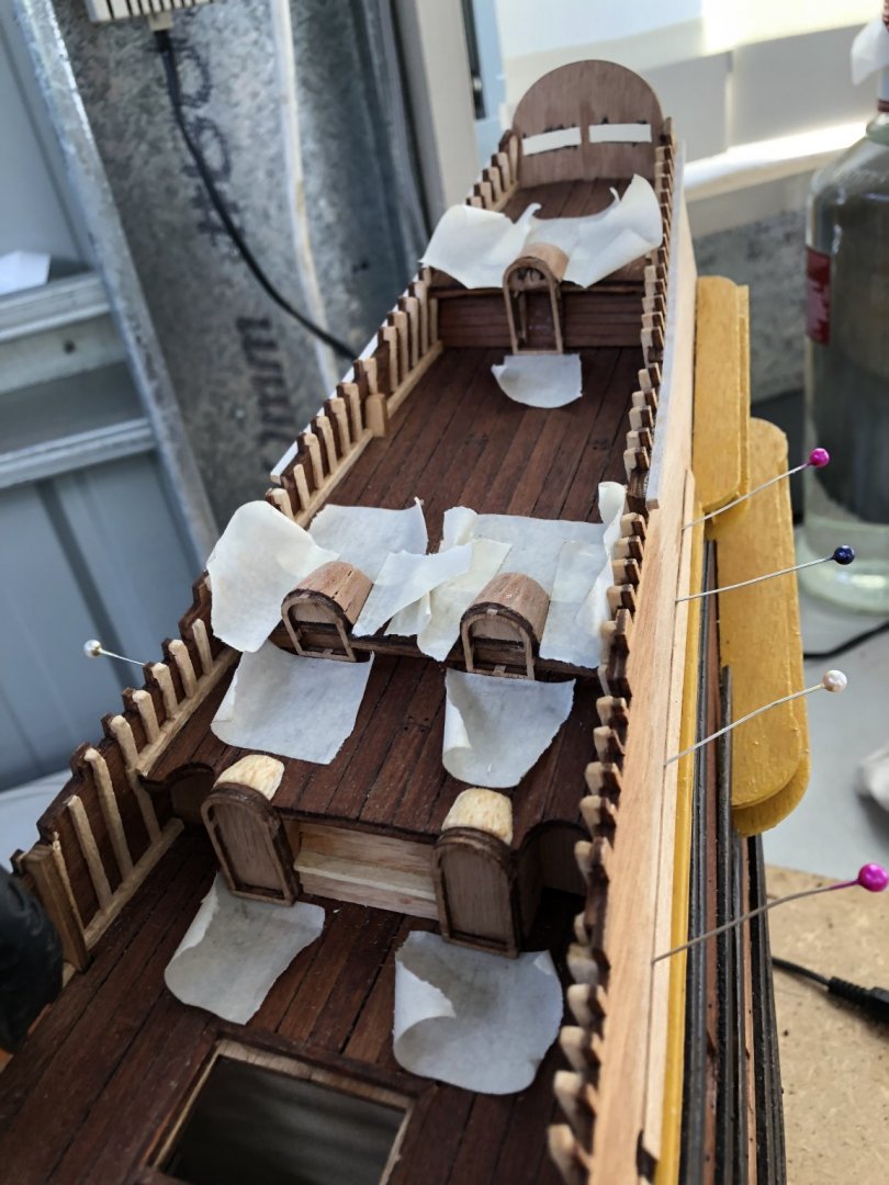
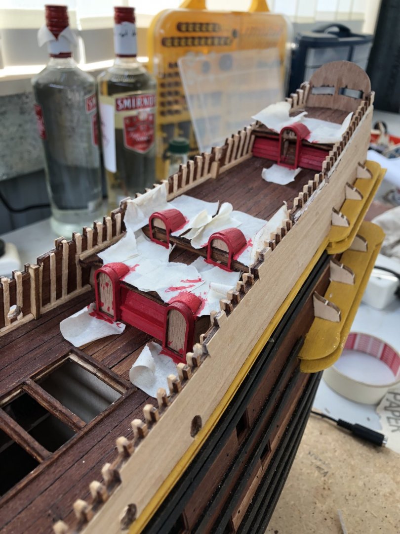
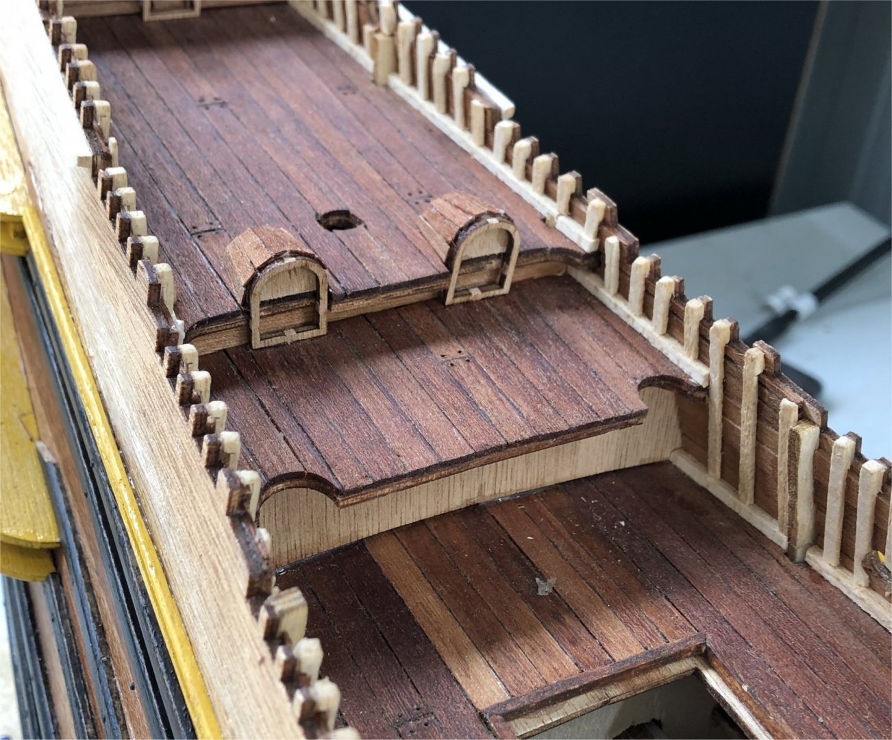
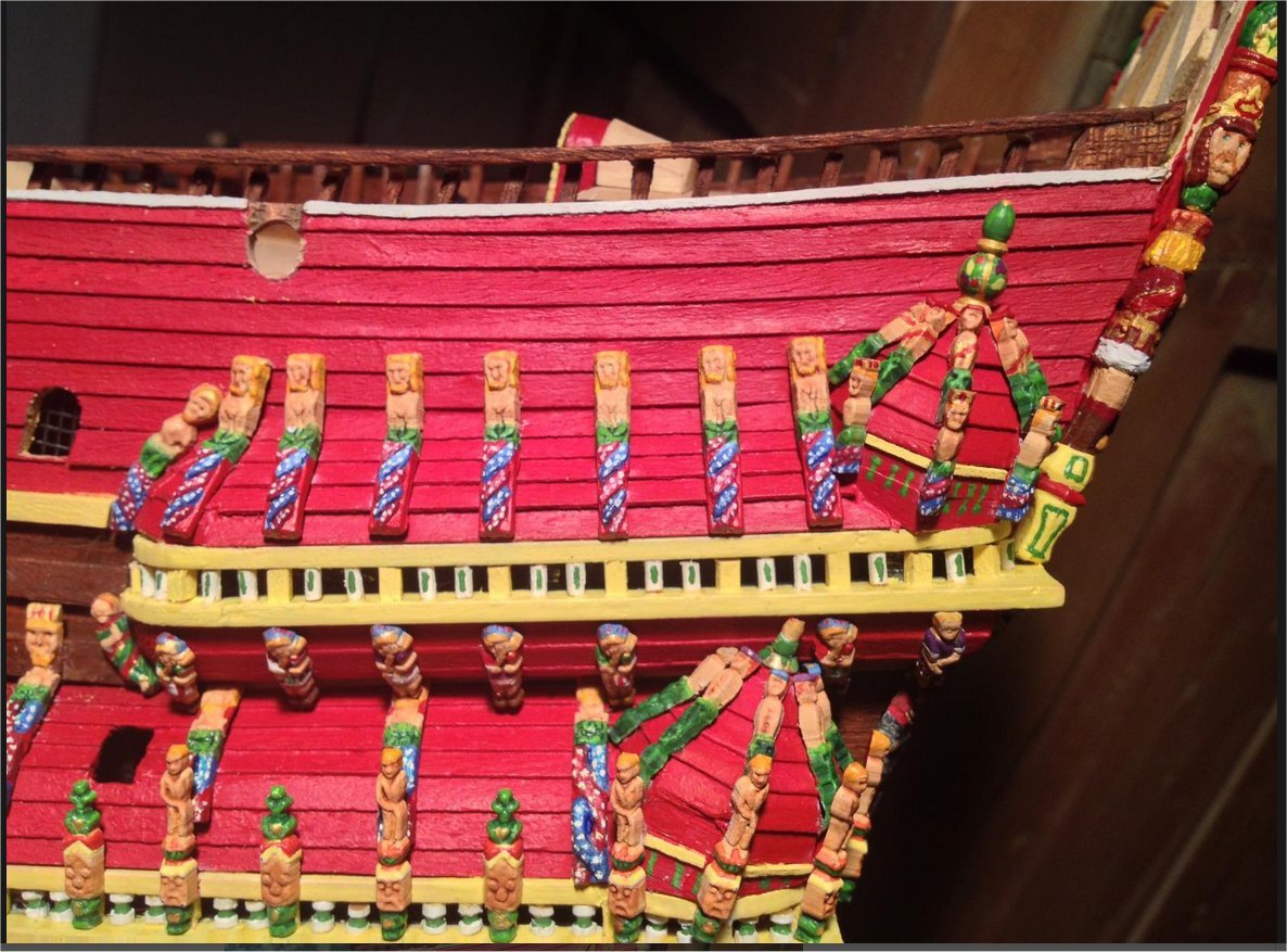
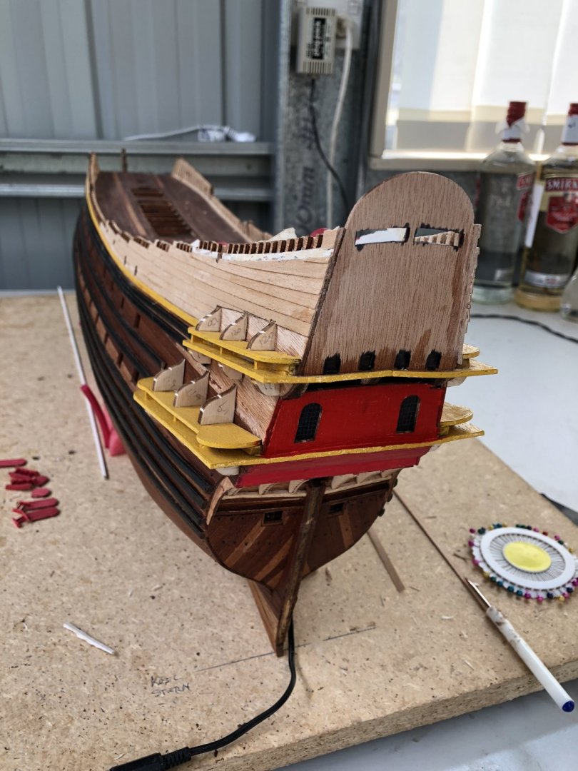
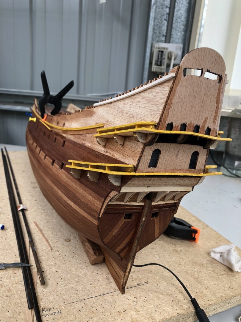
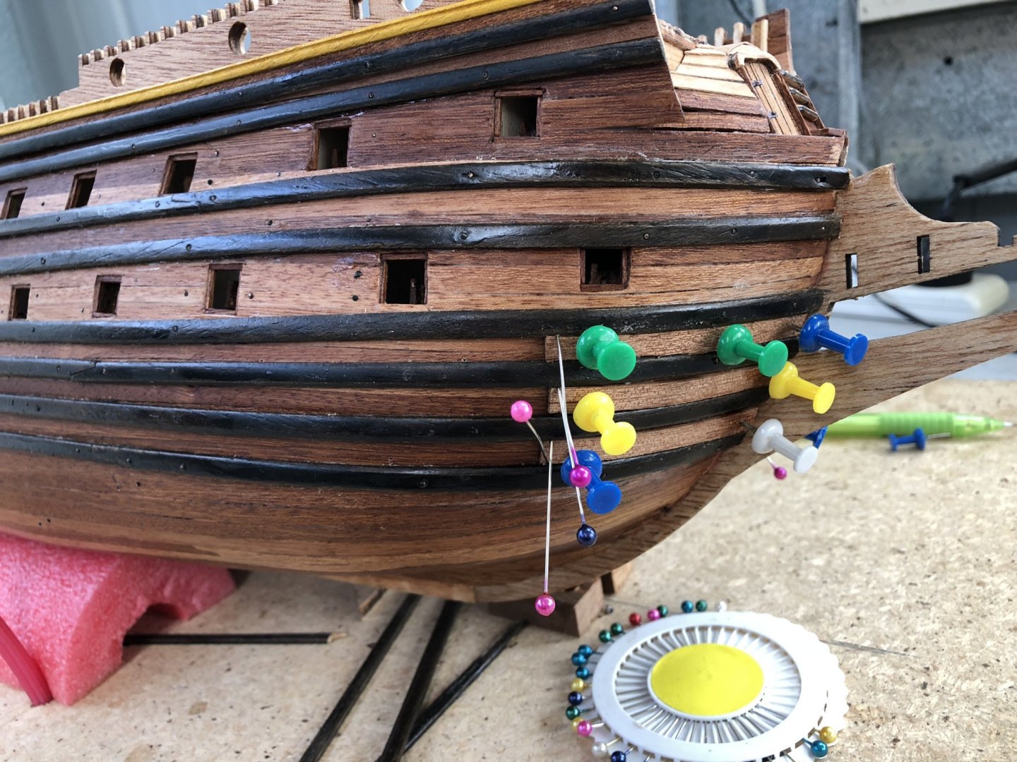
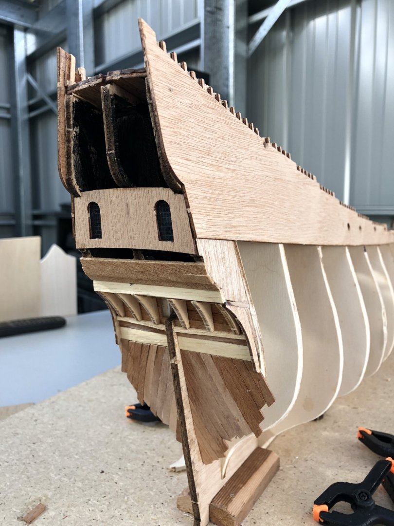
 The really high stern section of the model you can be seen below. The galleries on both sides can also be seen to extend to the port and starboard sides quite a long way. A clean-up of painting is required to give a better finish but that can wait until the structural work is done. The upper panelling is covered by figurines and sculptures and so the finish as shown, is largely hidden. The ports, where they extend through to the deck are painted black. Gunports are located on either side of the rudder stem and these will eventually get gun doors and cannon barrels fitted. The turrets of the galleries on either side of the ship are fitted only temporarily. These turrets and their fitting/shaping has worried me a lot as the instructions and the dimensions, while precise, were only correct on a perfect ship. I don't think the shapes, the fit and the angles would allow any kit builder to make the perfect ship!! It is really hard to get the angles and edges correct when effectively working in three dimensions in fitting these turrets. Billing's supplies six turrets (three for each side). There are two sets each of different sizes and come as turned timber (not sure what the timber is, but it's really strong, very fine grained and hard!!). It's actually pretty good to work with and obviously has been turned from stock for the kit, but the angles and cuts needed to fit it to each gallery position takes a long time to judiciously cut, file, fit then repeat a LOT of times. The easier part of this exercise was to fit the clinker planking on the tops of the gallery's which run between the sides of the turrets. One thing I had to be really careful of in fitting and shaping each turret, was that the tops of each turret is fitted with a turned brass ornament that extends its height upwards. This, for the lower turrets, had to clear the upper gallery bases and still maintain an appropriate angle (ie vertical), but not extend too far away from the ship. Pictures from the real ship show the angle and ornaments of the turrets as below. In particular, the lower, rear ornament does not have much clearance from the gallery base above it. Each turret has yet to be lapped by clinker planking too and this will test my miniature joinery skills to the limit. Although an interesting exercise, the fitting of the turrets is really frustrating because you know that one cut too far, and the mistake cannot be undone, yet the shape has to be right. In the lower gallery too, about one third along its length is a small window opening. While this is easy to cut, its position is critical because of the spacing of the sculptures yet to be positioned along the roof of the gallery. I had to look at a lot of pictures of the real ship to position these windows correctly. Time Elapsed: 670 hours Regards, Peter G.
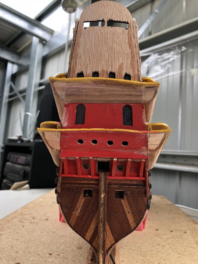

- 61 replies
-
- 5
-

-
- billing boats
- vasa
- (and 1 more)
-
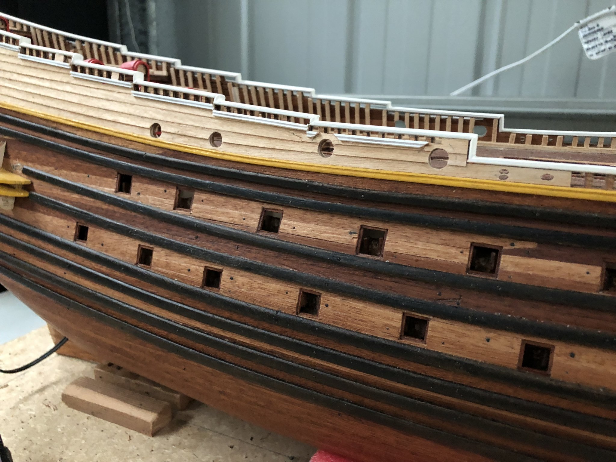
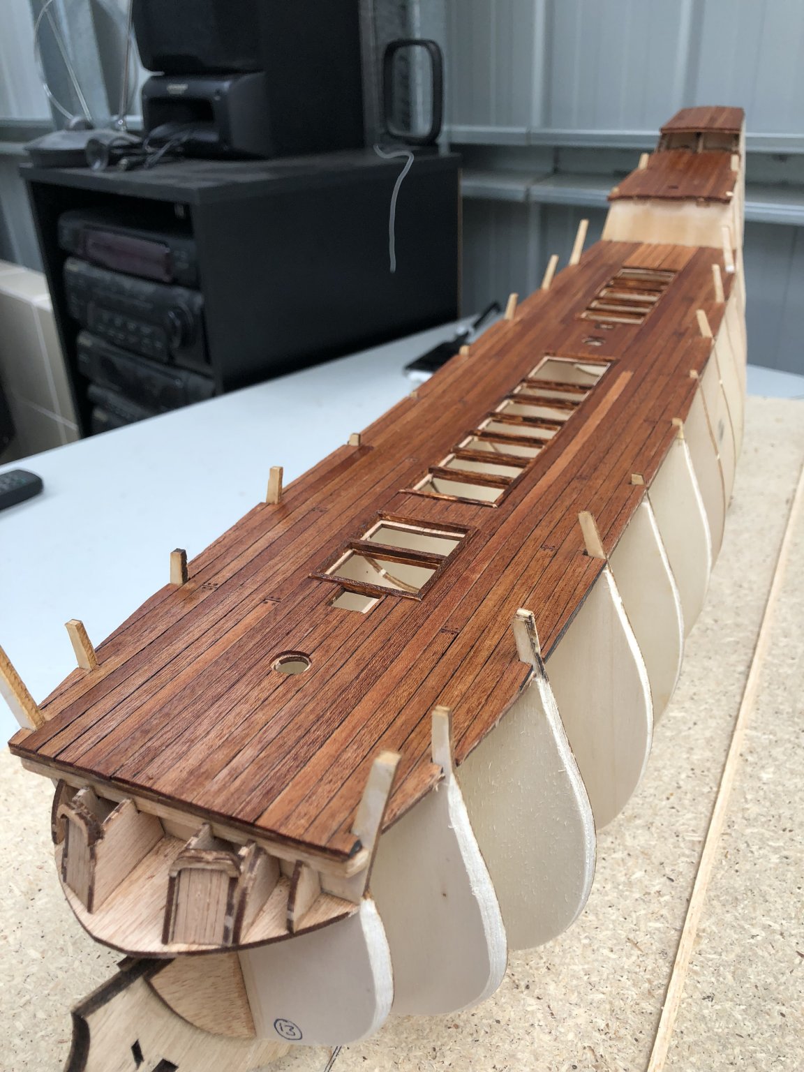
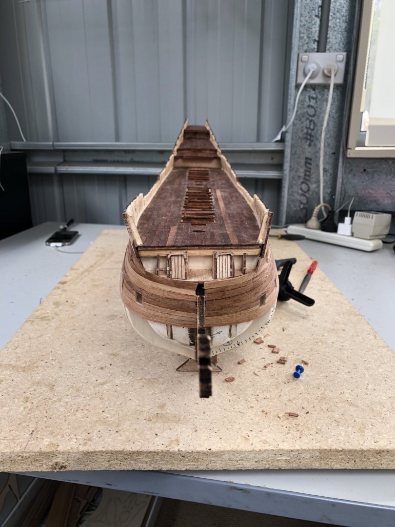
With the upper planking applied, I added a toprail (which is actually not the top, as there is another railing above this to be added later), but it forms the upper limit of the clinker, topside planking, as shown below. The upper planking is yet to be painted, but I have cut in the weather deck cannon ports where required. I also shaped a discontinuous wale which appears on the real ship. To do this, I have a small bench saw which I used to cut a small centre groove in a length of edging timber and then cut to the lengths I required (after painting white). I am pleased with this result as it simulates the real ship appearance well. The positions of each of the rear, stern galleries is defined by their yellow support bases as shown in the picture below, I have added mahogany planking to the rounded formers that define the upper and lower gallery shapes. I have turned the hull upside down to work on these galleries and this makes the task much more accessible. Sanding of the mahogany planking makes the shape smooth below the galleries themselves. Above the galleries, the covering is more clinker planking. The shapes of the galleries at the forward end are rounded and so balsa blocks have been shaped and added to give the rounded form required. In the picture below, the longer starboard front of the gallery awaits positioning and gluing while the upper gallery has a balsa block cut but not shaped. While working near the stern, four round portholes are required above the Captain's Cabin, so I drilled these and cut/filed out the holes. I drilled a series of small holes in the shape of the portholes rather than using a larger drill bit. I did this as I was concerned about tearing some of the timber and thought this was a safer approach. The outer, perimeter of these portholes is to be rimmed with copper wire to give a clean edge and finish eventually. Time elapsed: 605 hours Regards, Peter G.


- 61 replies
-
- 4
-
-
- billing boats
- vasa
- (and 1 more)
-
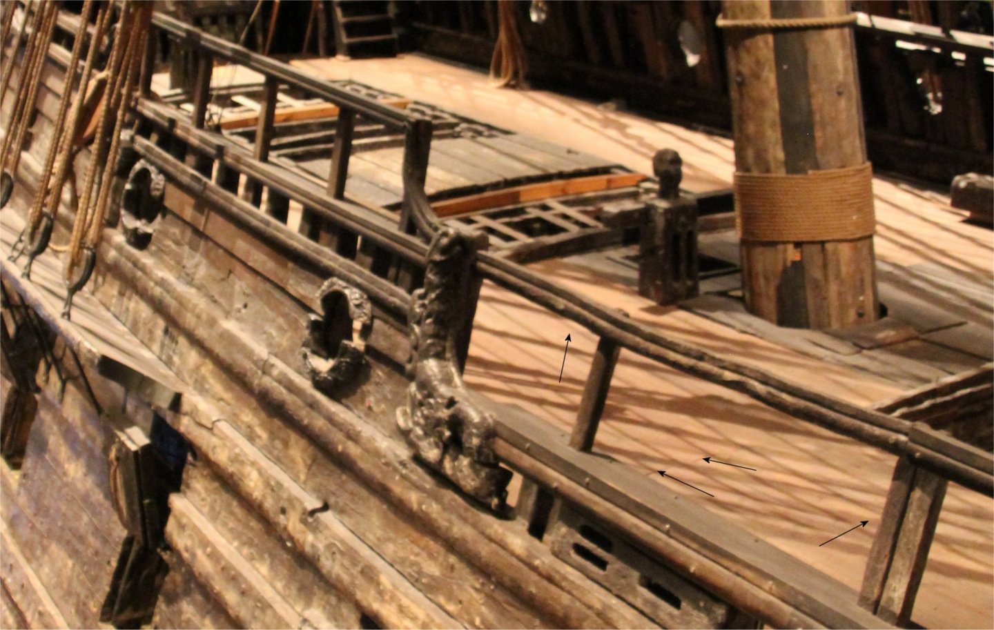
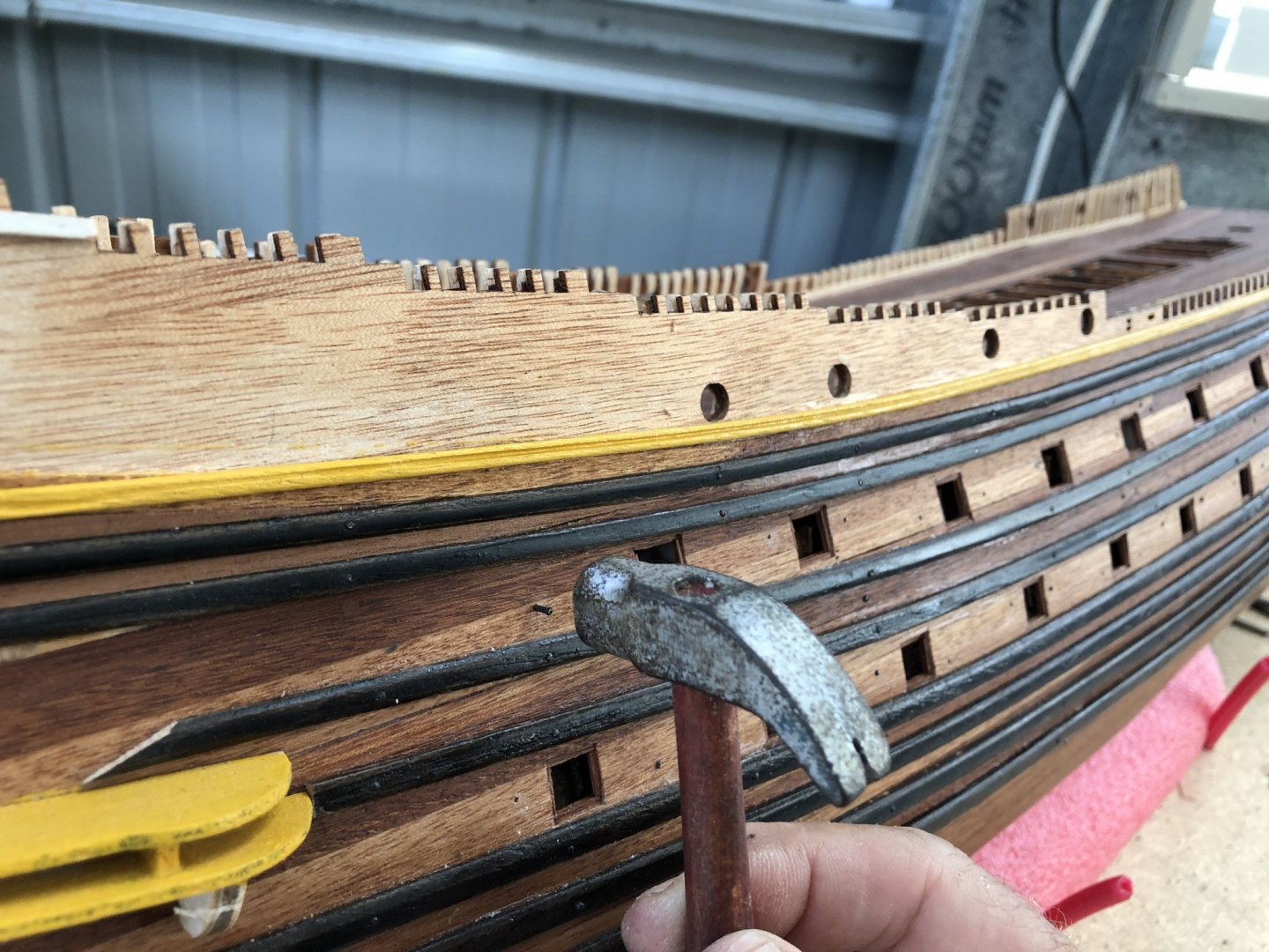
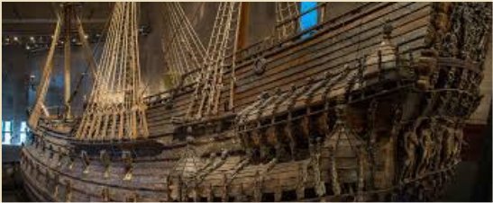
My next venture into using the chosen red paint, was to the newly completed cabin doorways and entrances to below-decks. Some clinker planking (as for the outer topsides, was also used in the internal weather deck areas, and these were also painted. In the pictures below you can see the masking of the deck areas to protect any mishap and below that the paint used for these items. Just in passing (I should have mentioned it a few posts ago), the decking was laid with mahogany strips, similarly to the hull. Joints however were butted but not in any regular or geometric way. There are a number of logs which go into the best way to lay out deck joints and the various patterns used (eg 3-4-5 planking and offsetting), however, for the Vasa, this all predates these systems. The deck planks were laid relatively haphazardly and a picture below shows this, although it is subtle and hard to see. I have added arrows here a butt joint is evident. So, this is more or less the way I have laid my model decking. In the decking I have done, I was unsure of how to finish the deck planks, with nails or no nails at the joins or over bulkheads etc. In the end, I have placed four drillholes at each plank butt joint, and used an HB carbon pencil in the hole to add a bit of darkening, before the deck was finished with burnishing oil. This seems to have worked quite well (see photo below the next). One of the next tasks to be addressed, while the hull is relatively unencumbered by cannon doors, chainplates etc, is whether to add nails. In the 'real' Vasa there is an ongoing programme of nails being replaced by bolts to hold the ship together into the future. The nails are simply corroding and giving away, but to add nails is a BIG job and difficult to get right at this scale (1/75). I have seen comments (I think in Clayton's Vasa scratch build), that there were over 3,000 nails added and this therefore is a major task. So, I thought, I might attempt a few and just see how laborious the job would be. Firstly, how to get the scaled nails. At least two sizes were required, some for the planks and others which appear larger and seem to be used in the more strategic, strengthening parts of the ship's hull. Below is a small portion of the actual ship's starboard bow area. The nails are evident both in the hull planking but also the wales, but these are different in sizes. In reality, there is probably a range of nail sizes used, but for practicality in modelling, I chose to create only two sizes. The next question was, should I purchase scaled nails (eg model railroad track ties etc), or should I attempt to make them. Making them seemed a daunting task until I came across the brilliant Youtube video by the Russian Alexey Domanoff (this guy is a genius at invention)!! The video is at the link ( ). The video uses simply brass or copper wire (of varying thicknesses), which is cut into lengths, made straight by rolling, and then a blunted but angled knife blade edge is simply rolled across the lengths of wire at intervals. The pressure of the knife blade swells the wire material until it breaks/is cut and lo and behold, there is a small length of straight wire with swollen heads at each end. If you cut each short length, you get TWO nails - PERFECT. Using Alexy's method, you can generate quite a lot of nails in a short time. I generated about 2-300 of two different sizes/thicknesses from two different wire thicknesses. I then placed these into a container, and added some blackening fluid. I used Birchwood's Gun Black (used for blacking the brass shells of gun ammunition) and it works extremely well. You just insert the copper or brass, leave for about 1-2 minutes (depending on how black you want it), and then rinse off in water and let dry. It leaves a slight residue on the items that being blackened which can rub onto your fingers, but nothing that some good soap won't get off. Having made copper nails, these were not strong enough to hit into the timber of the hull without drilling. So, I drilled a series of holes and then followed with the nails. I did this at strategic locations (eg plank joins, over ribs/bulkheads, around the stern etc etc). Below are pictures of the process. It was not hard, but it did take a few days of work. I estimate, I have inserted over 500 nails!!! With the holes drilled, I then inserted the nails and tapped them home. In the end, I was quite pleased with this nail appearance. The nail heads are close to scale, they are for effect rather than structural, but that's OK. Given that the original ship is SO pockmarked by nails around the hull, to make a better representation of the real ship, in the end, I felt the nails added that bit of extra detail and realism. All for now. Time elapsed: 595 hours Regards, Peter G.


- 61 replies
-
- 4
-
-
- billing boats
- vasa
- (and 1 more)
-
Great building David. Two questions: 1. The Victory is on my 'bucket list' (if ever I finish on my current Vasa build), so what is the kit make? Is it Corel and how have you found materials, instructions etc? Did you review any of the other Victory kit manufactures before deciding on this one? 2. What is timber of the planking? It looks light in colour so I am assuming Obechi, but what does the kit say? This is the first planking and are the timbers the same for the second planking as the first? If not, what is the timber of the second, finish planking? Excellent effort, she will be a fine model. Regards, Peter G.
-
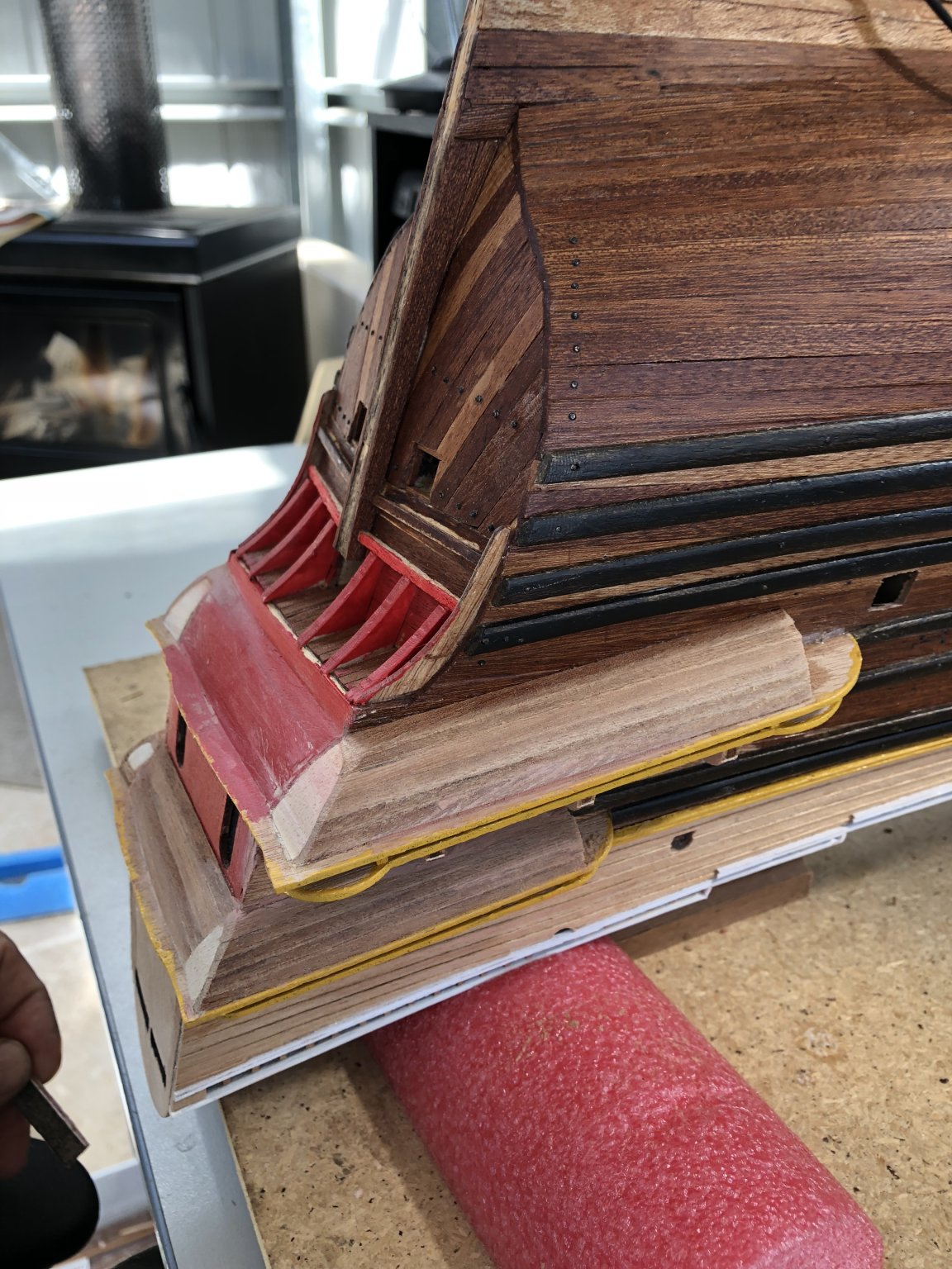
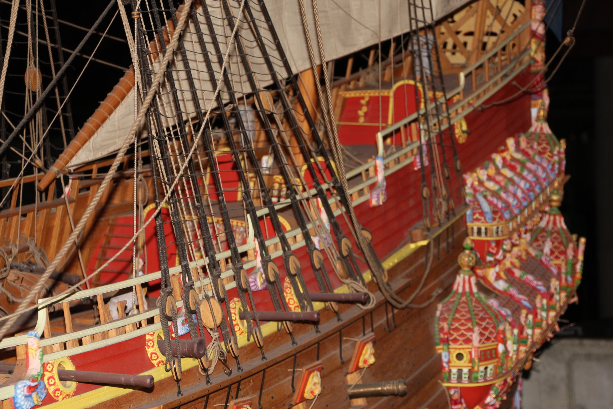
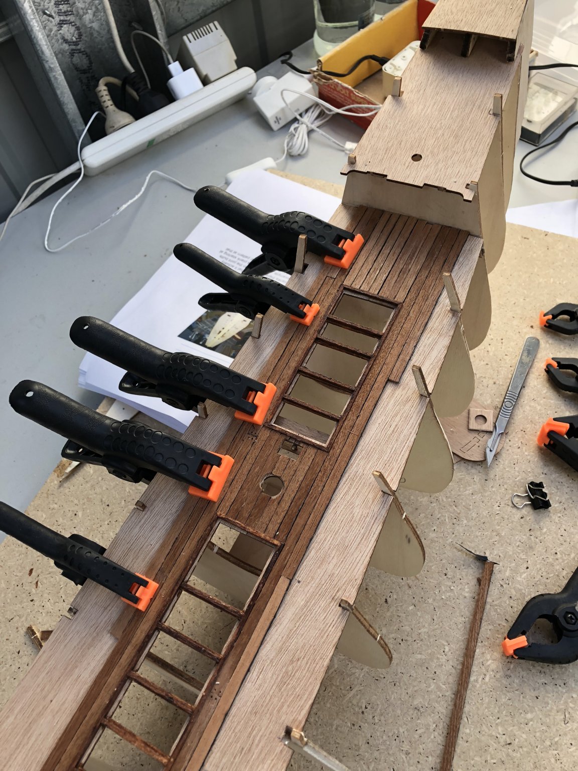
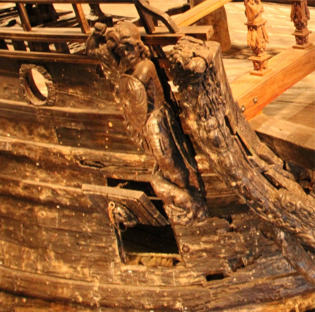
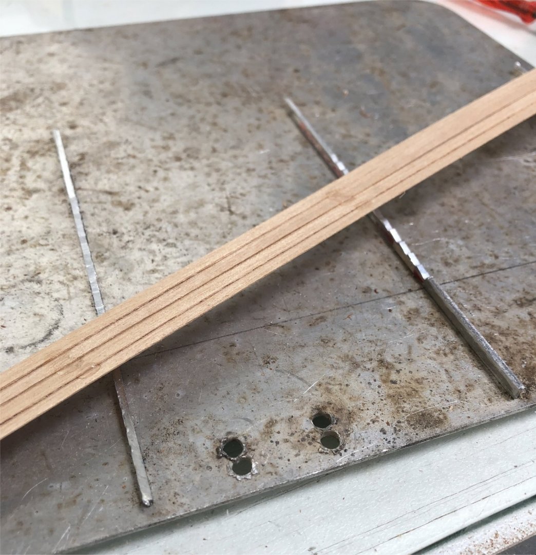
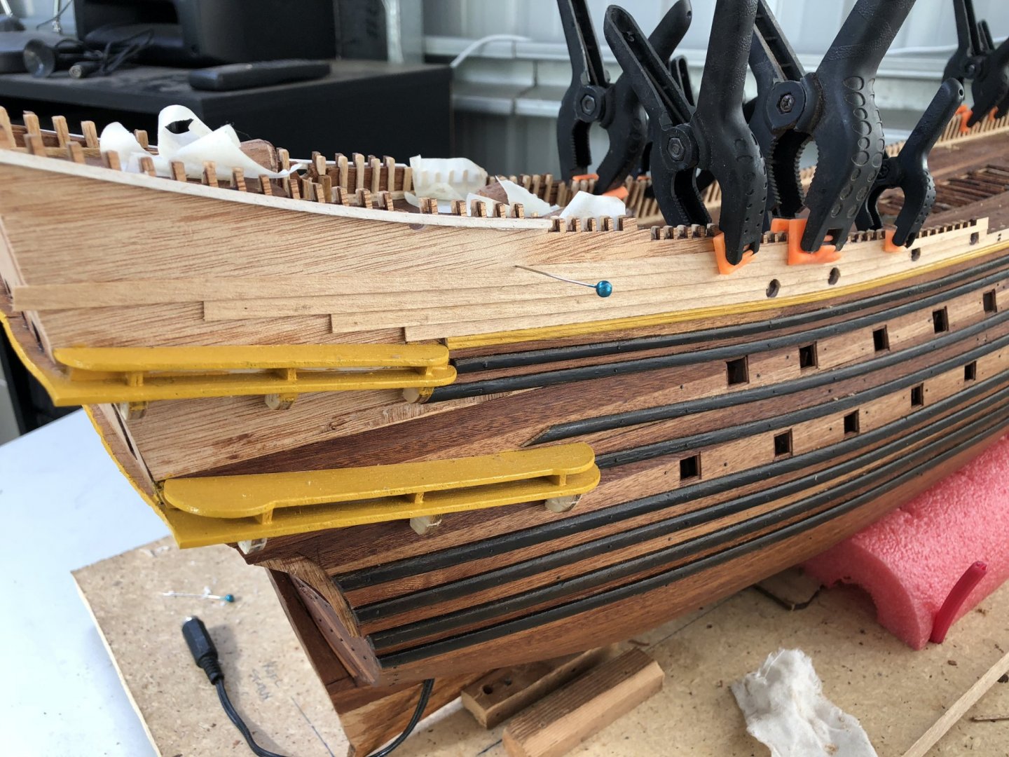
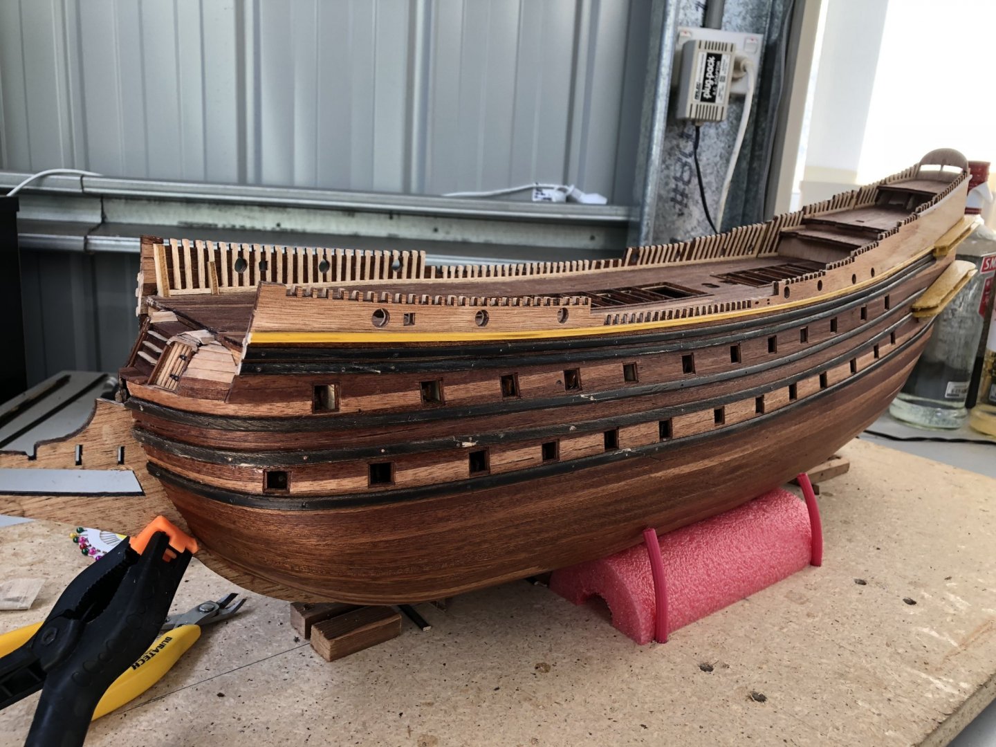
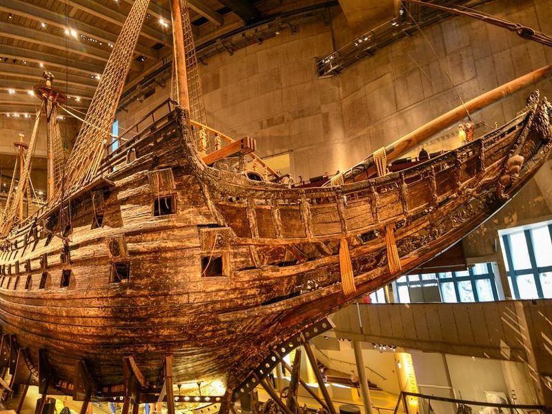
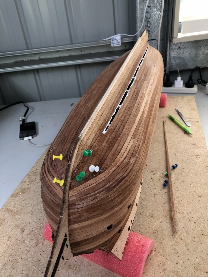
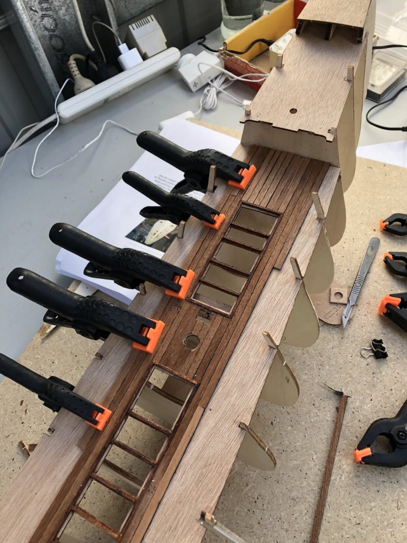
The topsides of the Vasa, above deck level on the outer surface and above the hull planking, was clad in thinner clinker, overlapping planks. A photo of the actual ship in Vasamuseet is shown below. The photo is taken from the rear towards the stern quarter. In particular, the outer cladding above the complex galleries shows the overlapping, clinker planking. This planking continues to the midships where there is a gap infilled by railings, and then it continues again in the foredeck cladding. To assist with an even overlapping planking, I used kit-supplied Obechi timbers, but I made a jig which I used to ensure the alignment of the planks was even and precise. On some aluminium, I CA glued a series of aluminium strips which I had shaped by filing a 'saw-toothed' shape into the upper edge. The photo below shows this. The saw teeth were made at fractionally smaller width to the timbers I was using. So, by laying the timbers into the grooves and ensuring they butted up to each sawtooth, an overlapping, clinker pattern was made. Some judicious placement of glue at certain positions along the timber length, then allowed the pattern of the planking to be retained, but still bent as required to fit the ship cladding shape. I wasn't able to glue the entire length of the planks, as I could then not bend the collective planks. The picture below shows some of the clinker planking being added to the topsides near the stern. I have used PVA glue and a large number of clamps to secure the planking. Once the planks were fixed, I drilled out the cannon ports for the weather deck. Forward, the planking was also added, but the low number of planks to cover the required topside area precluded the use of my clinker 'jig' so in retrospect, it probably was not worthwhile developing this tool. The topside planking lies adjacent and hard up to follow the shape of the uppermost wale (which is yellow and lies above the lower black wales). The picture below shows the area in the midships where the clinker planking does not exist. Interestingly, there has been conjecture for many years as to whether this cladding was raw timber, coloured and if coloured, what is the colour? Significant research by the Museum suggests now, with the actual ship available (albeit having been in the Baltic waters for 333 years), that this cladding was coloured. In early models of the Vasa (and in fact the picture on the boxed kit by Billing Boats), indicates the colour was blue. When the ship was raised and after the research however, it now appears that the colour was more likely red. This colour was the colour of royalty during the 17th century and the pigments for painting blue were difficult and exceptionally expensive to obtain. I did a lot of experimenting with the 'red' colour and looked at a number of other Build Logs to determine the red colour that I liked. The one I thought most appealed to me was the actual 1/10 scale model which exists in Vasamuseet. Below is a photo I took while in Stockholm where this excellent model is on display beside the original Vasa. Before applying the red I chose to the side planking, I thought I would experiment a bit and added it to a portion of the stern where, if it was not right, it was eventually to be covered by largely figures and structures. Below is the result I selected before applying to the topside planking of the rest of the hull. The colour looks good and I like its effect, so this is the paint I will use. It is an acrylic made by a hobby paint company called Vallejo. The colour is Carmine Red (No. 70.908). The contrast with the yellow timbers is strong and will be a highlight of the ship. Time elapsed: 525 hours Regards.

- 61 replies
-
- 4
-
-
- billing boats
- vasa
- (and 1 more)
-
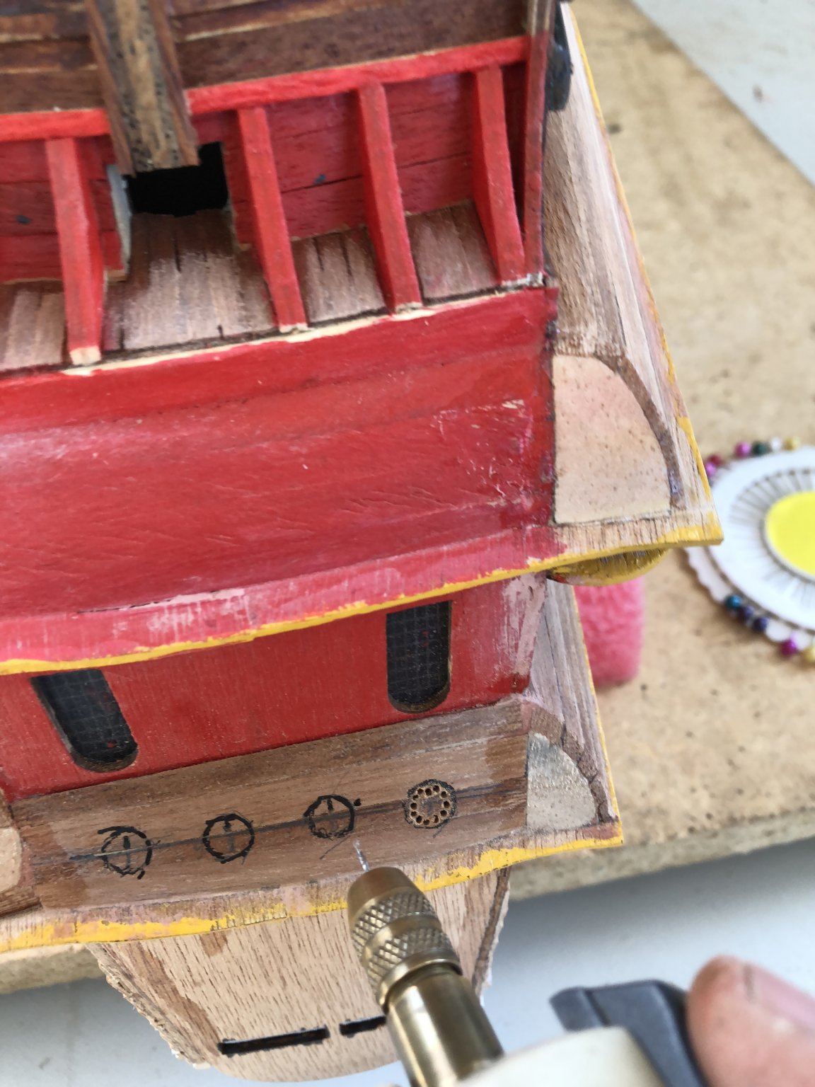
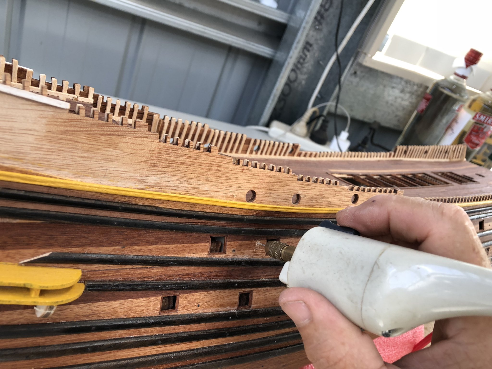
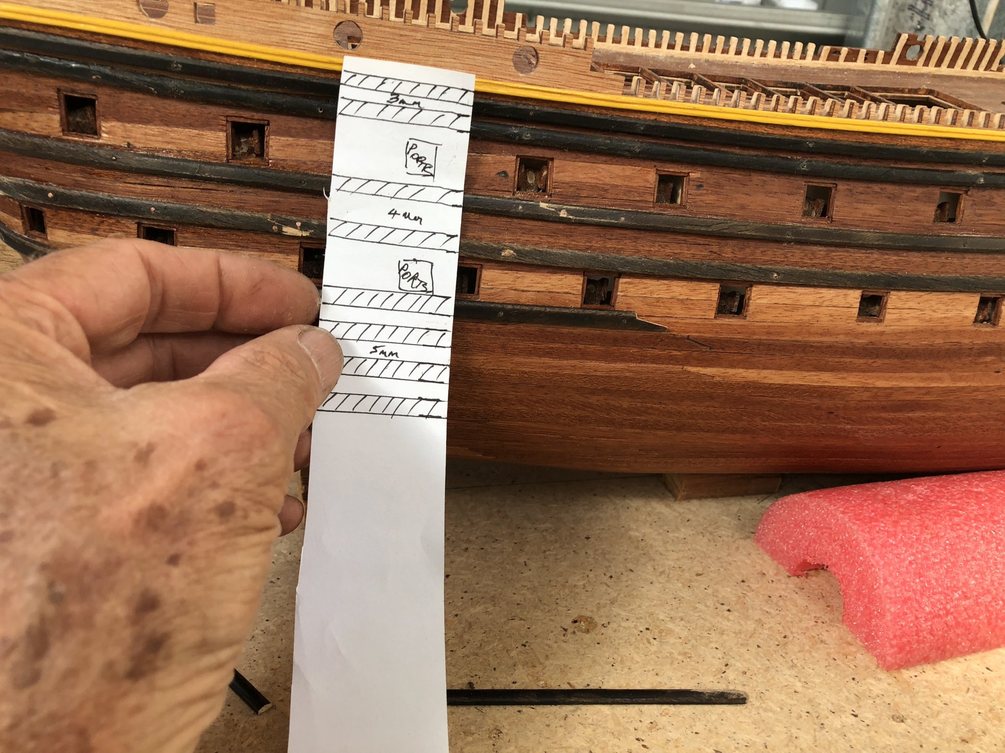
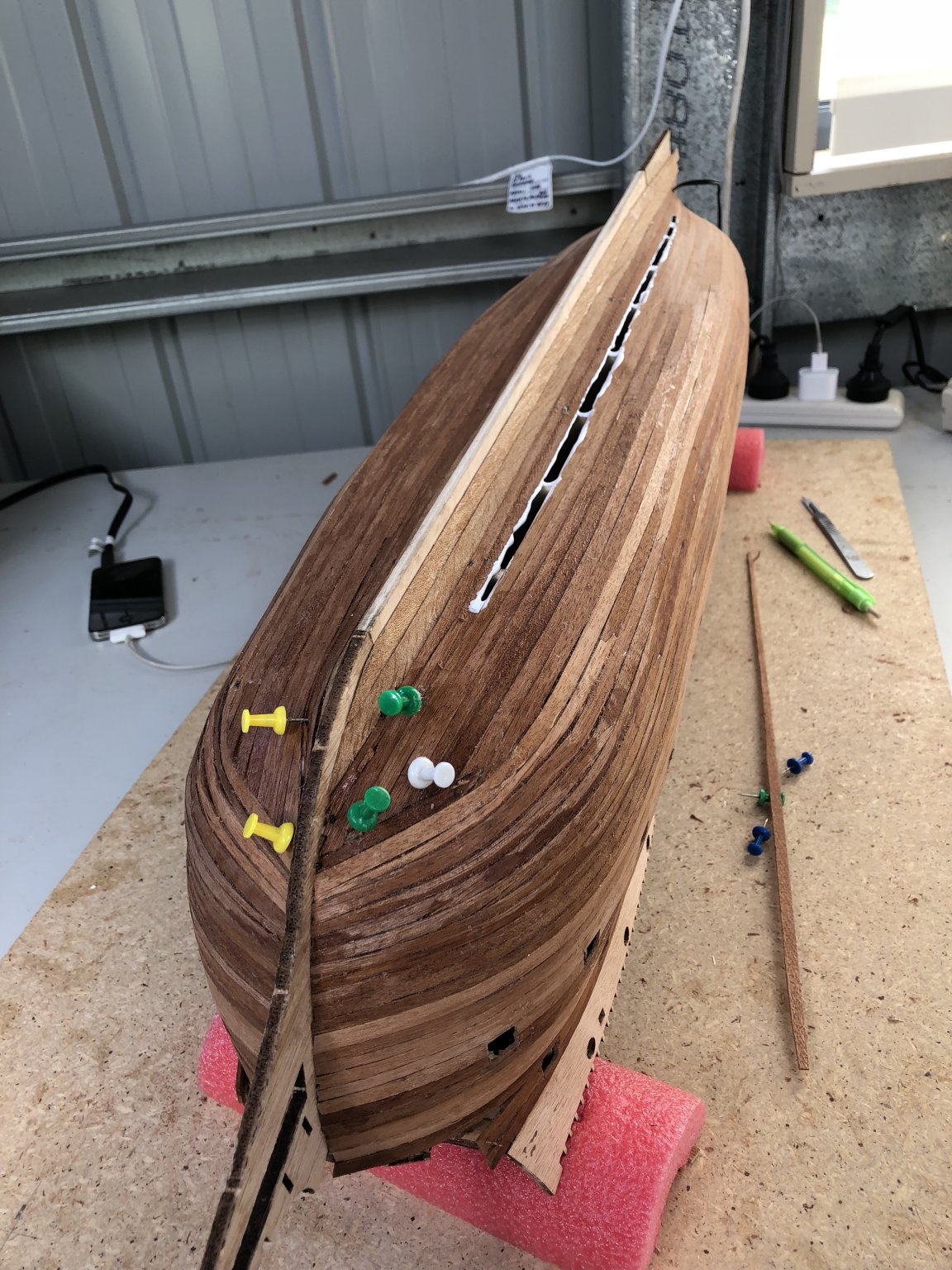
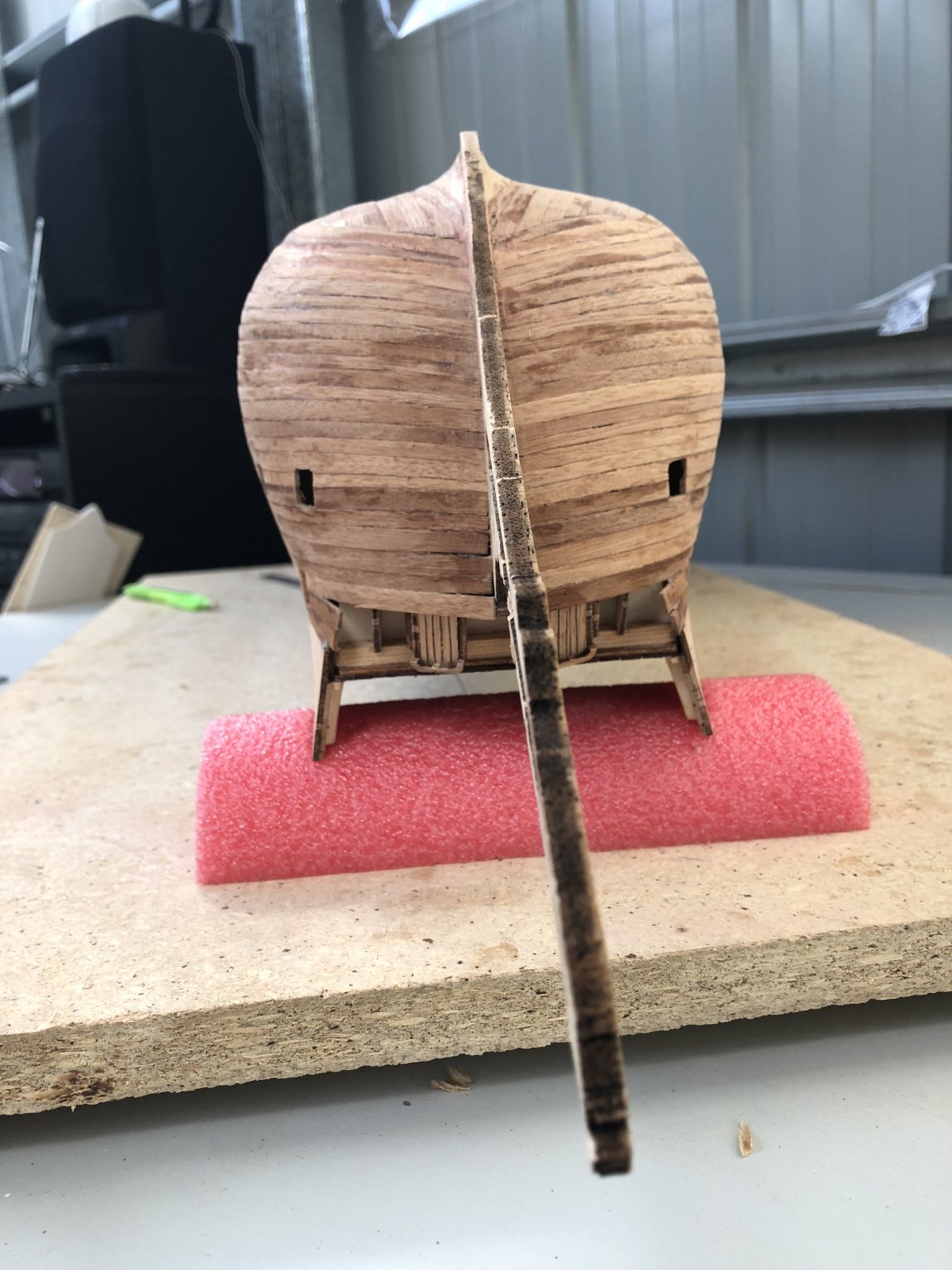
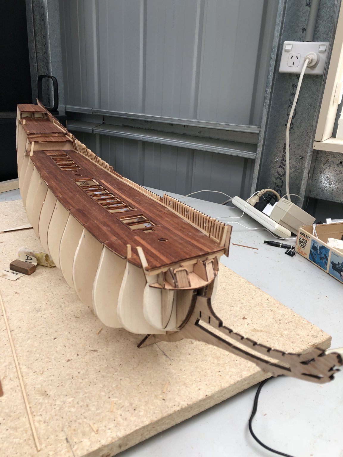
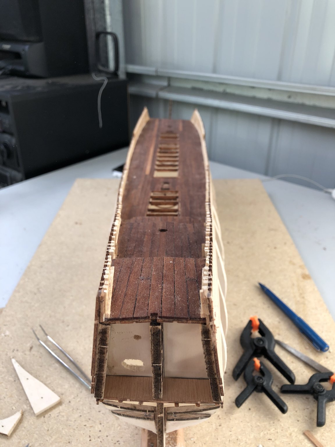
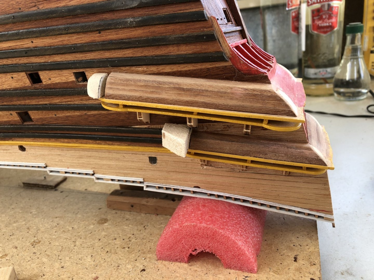
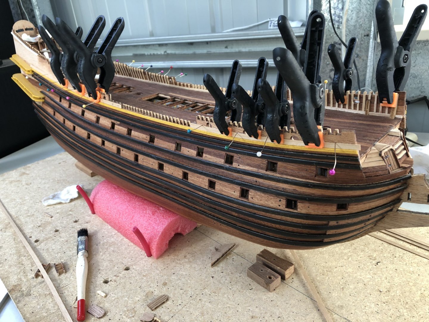
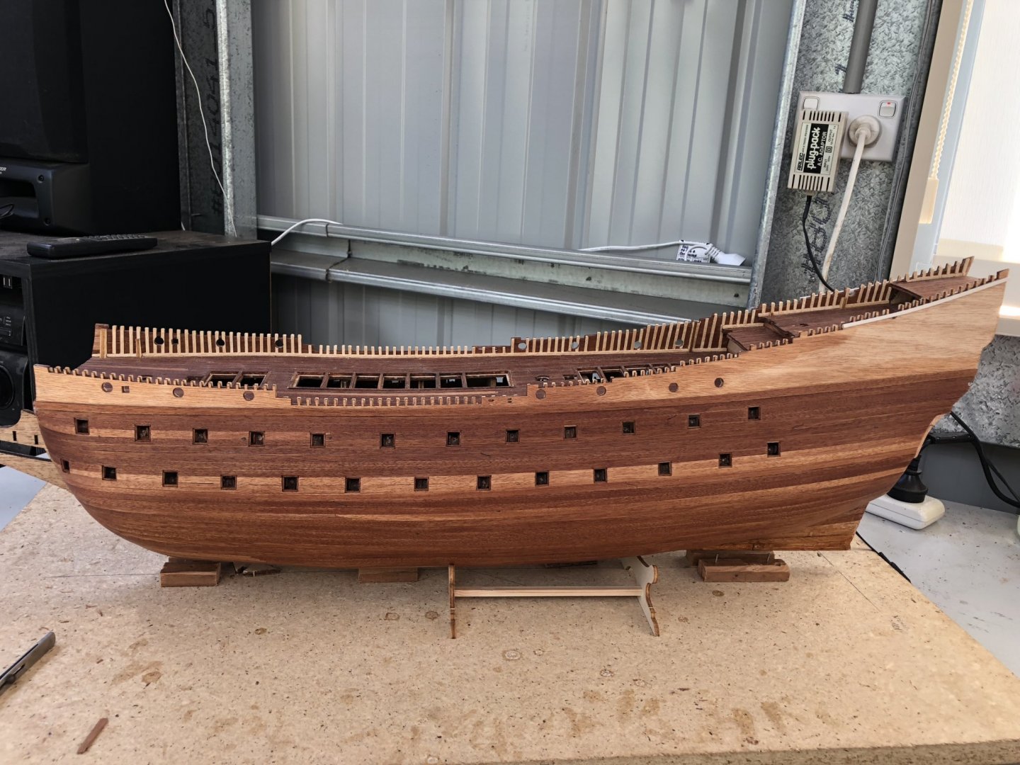
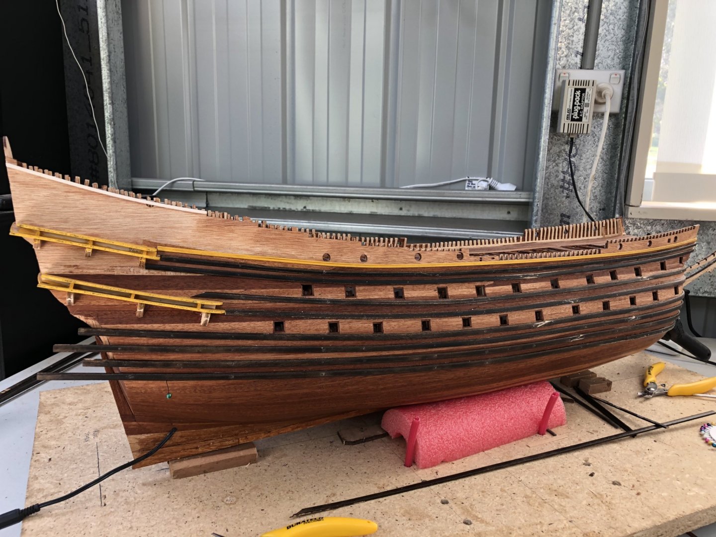
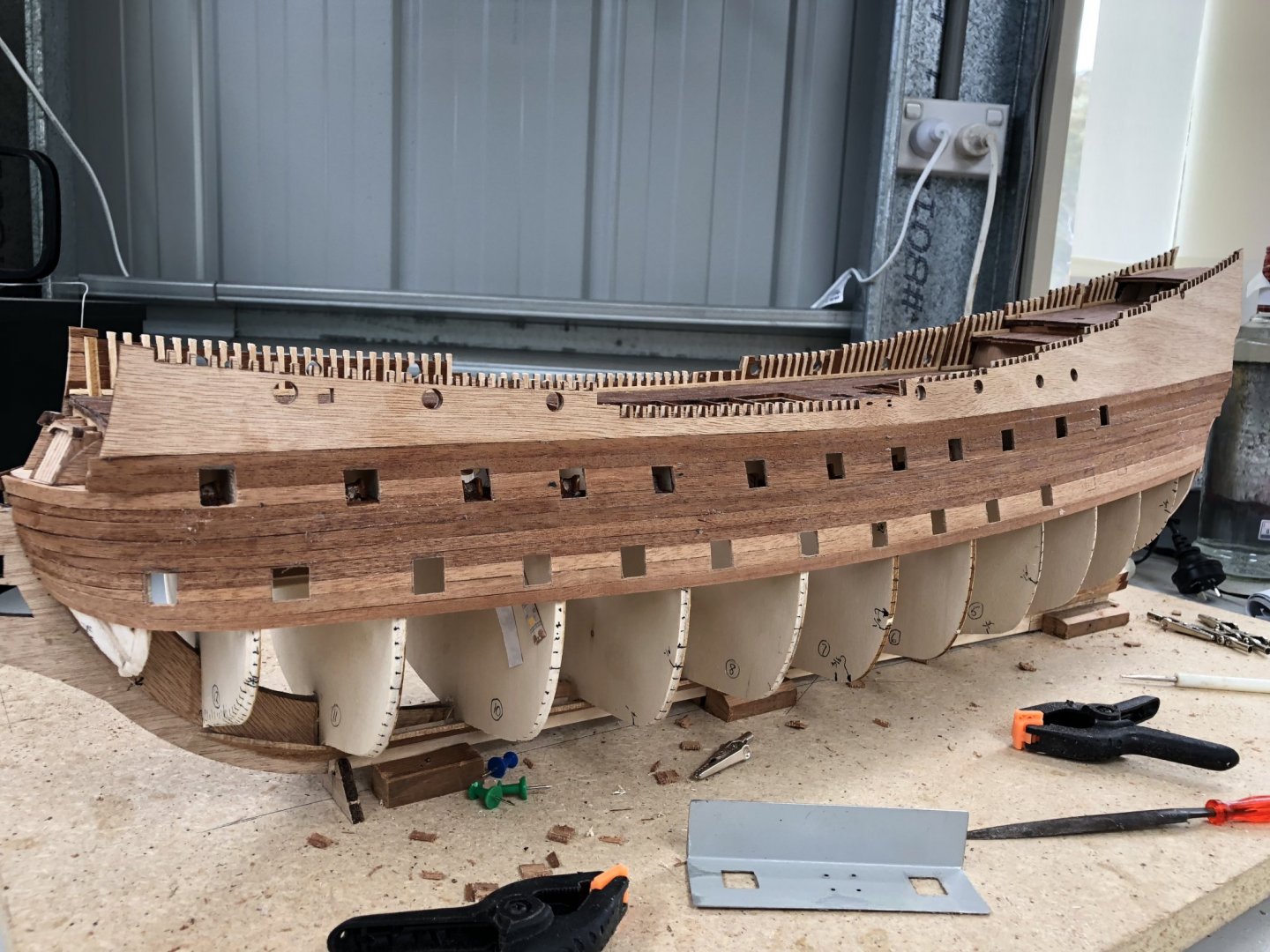
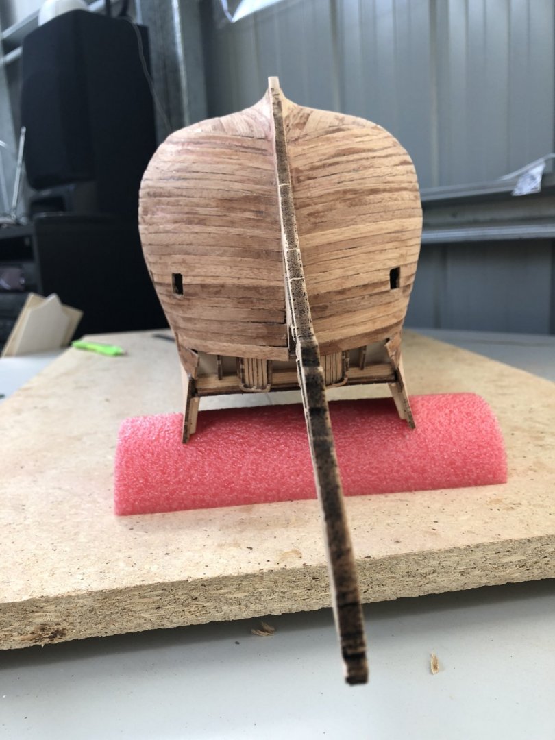
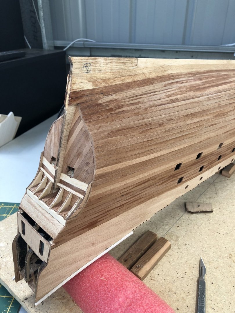
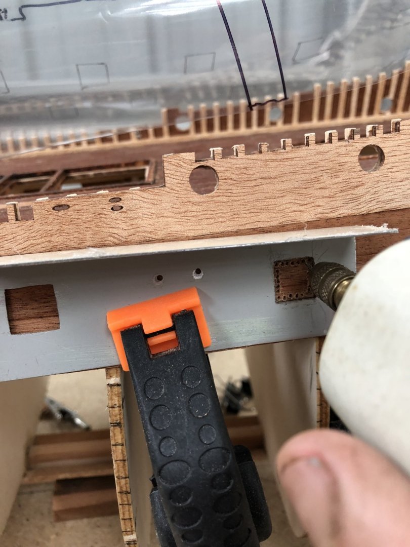
Finishing of the hull is now completed. I added filler where required (see previous post) and did some sanding with moderate and then finer sandpaper. I only hand sanded and this seemed to be adequate to give a relatively smooth finish. I used an oil-based varnish with low sheen and this seemed to provide a really good even appearance to the hull. It brings out the natural colour of the mahogany nicely. The lighter colours of some planking is probably not too realistic, but when the wales are fitted, it will not be too obvious as these are black and there are a few of them. The rear galleries required timbers which are positioned around and across the stern. I prepainted these yellow and fitted them where indicated in the instructions and plans. These form the starting points and alignment of the wales and are also the supports for the gallery domes which will have to be made and shaped. The top yellow deck gunwale has been added and this follows the curvature of the deck. In the image above you can see the wales (black) lying on the base which are to be positioned and attached soon. I have also added some extra enclosing timbers to the stern including the upper cabin portholes/windows. These, like the Captain's Cabin also have the flyscreen glued inside some shaped acetate sheet to give the impression of leadlighting with the LED lights on internally. This gives a good effect at night. The wales had to be positioned along the sides of the hull at specific offsets from the deck and topsides, so I made up a paper 'ruler' that I used to locate these, as shown below. Joints in the wales, just like the hull planks are angled to form correct butting of the timbers as on the real Vasa. I have used copper hand-made nails for securing the wales. These nails too I have made for use in the hull timbers, but these will be added later. More on this then. In the image above you can see the internal gun carriages inside the gun ports. You can also seen that for each port, I have added a thin 2mm timber surround for each gun port. Billings supply plastic gun port surrounds which match their plastic gun port doors, but I don't much like these because: 1. The sizes don't match the two different gun port sizes from the upper gun and lower gun decks and 2. I don't think that they look as good as natural wood. The final wales added to the hull are shown below. I pre-painted them (for obvious reasons) before attaching. Actually, it was not paint, but a black stain called 'Japan Black'. Two coats of this seemed to do a great jot and gave a good natural grain texture left without a smooth finish from paint. Some touch-up will be required when all wales are attached, but that should be a simple job. The wales as they are added along the hull in the picture above. The nailheads I have used are exposed and will need painting. Three more wales to go below those there already and down to the waterline. Below the extra wales are in place. Some touch-up of stain is required. In the above photo of the hull to the stern, you can see how the wales align with the galley timbers. The galleries take the majority of the figures and sculptures and this is a major job ahead, so they need to line up accurately. Yo can also see at the base of the hull, near the stern, the wiring that leads to a plug for powering the LED internal lights. Another shot of the wales below and the wrapping around the bow which required some extra support for the glue (pins and push pins unfortunately). Also, at the bow of the ship, there is a second layer of planking on the real Vasa (probably to make her a bit smoother in the bow cut as she moved through the water). These timbers were also probably to protect the bow as the anchor is lowered and raised - Clever thinking seamen in those days. These extend from bowsprit extension to just below the anchor line. On the real Vasa, you can just see these timbers in the Museum in Stockholm (see below). In the real ship, you can also see the position of the deck extension that is used to lower/support the anchor. This lines up with these timbers of extra planking. The real ship does not have the coloured wales (eg stained black), but research by the museum staff indicates many of the colours used on the ship back in the 1620's. This especially applies to the over 200 figures and sculptures that adorn this ship. This will be a major exercise to paint etc, but I am looking forward to it. Time elapsed - 490 hours. Peter G.

- 61 replies
-
- 6
-
-
- billing boats
- vasa
- (and 1 more)
-
Many thanks Retired Guy and Johnathon. Encouragement at this stage which is a bit tedious, is great!! Continuing on with the planking. Planking, planking and more planking.... The bow of Vasa is quite rounded and bluff and so some severe bending and shaping is required. The picture below shows the slow progress beneath the first decking level of cannon ports towards the keel. For the bending and plank shaping I have found the following procedure most effective using mahogany 1.0mm planking timber. 1. I pre-form the plank to the right width and chamfer where required. If a join is used (which is on most planks, the diagonal offset is cut and shaped for the next plank along. 2. When happy with the shape and fit, to the 'lining' width defined for each bulkhead, the plank is inserted into a long tube and boiling water added so the entire plank is immersed. I leave this for 3-4 minutes. 3. I take out the plank and then I have a jig made out of 2 x 4' (50 x 100mm) timber that has on its thin edge, a semi-circle of reducing radius cut. This shape allows me to bend the plank into the timber until the correct curvature is obtained. Actually, I usually over-bend the plank so any 'spring-back' approximates what I require. 4. For parts of the plank that require excessive bend (such as the bow, I also use a heated round electric soldering iron to push the plank down into the space of my timber shape. With the water in the plank, there is no burning, but a little steam is created which helps the bend. 5. The plank is then quickly migrated to the hull where pre-gluing has been added (using white PVA glue), and the plank placed into position. The plank is held by preferred paper clips (as shown in picture of previous post), or by push pins into the bulkhead. In the picture above, planking has progressed to be just below the second decking of cannon ports, which have been positioned and cut. Note in the first deck level below the topsides, you can just see the 'false' cannon carriages and individual decks to mount the below top deck cannon barrels. This was tedious work but so long as it is done as planking progresses down the hull, it is not a time consuming task. Above the planking is the topsides plywood. Billing Boats use this as a base material which on the real Vasa, has a series of clinker planked, thinner timbers to be mounted. This will be done after hull planking is completed. AT LAST, I am coming to the final plank. Below is the last plank to be fitted and the glue is in place. Additional plank support is required at the bow of the hull with pins placed to ensure there is no movement as the glue dries. The planking is tight and has only a few gaps where filler will have to be used to remove the hull plank gaps/openings. The shape of the hull is good and Billings have done a good job of the bulkhead shapes and positions to replicate the ships scaled shape. The finished bow below shows the curvature of the planks here. There is some opening and gaps between the planks but it is reasonably minimal and will take filler satisfactorily. I have used a minimal number of stealers and overall the planking has gone well despite being only a single planking designed by Billing's. In the image above, the bow looks slightly skewed, but the photo has not been taken directly head-on. When you look at it with the eye, both sides of the hull are symmetrical and it looks fine. Some mahogany timber imperfections that are apparent can be seen, but these will sand flat and with painting/varnishing, the finish should be good. At the stern end of the hull, the planking does not require such tight bending and so the planks are tighter and fewer gaps are present. Planking is now complete!!! Finishing will involve some minor filling of evident gaps. The filler I am using is a dark mahogany commercial wood filler and it appears too dark with some of the lighter coloured mahogany planks, so in the cases, I have sanded some light coloured planks to create a pile of mahogany sand/dust. I then added PVA white glue which dries clear and then used this as a filler. It works well and when varnished should almost not be visible. Next post will have the progress on the finishing of the planking. Oh, yeah - I have been trying to assess the times taken in the build to give an estimate of our build times. My estimates to date are: 60 hours Kit, background, planning etc 50 hours Bulkhead placement, shaping and keel 80 hours Decking, shape and ribbing 250 hours Planking, shaping, fitting and gun ports Total to date, about 440 hours. Its really hard to do these estimates, as we all get to be distracted by other tasks on the ship, have other commitments (eg family, work, etc. etc. and so a few hours hear and there mount up very quickly. These figures are a guide only and are NOT accurate, but probably not far off. It comes as a bit of a shock as to how much time these models can take!!! However, to do a good job, it does take time - but, isn't that the point of the modelling exercise!! More soon. Regards, PeterG.
- 61 replies
-
- 6
-
-
- billing boats
- vasa
- (and 1 more)
-
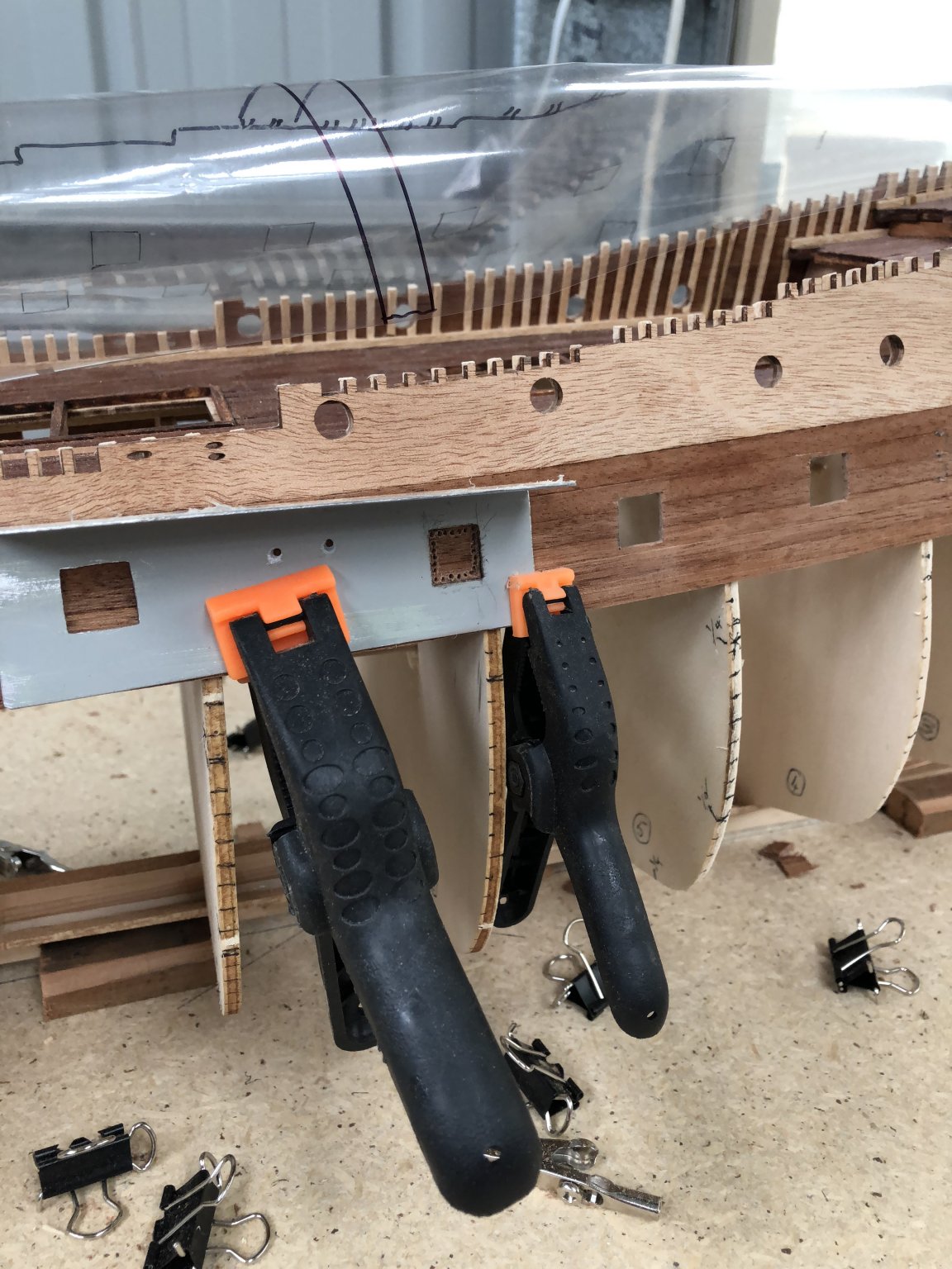
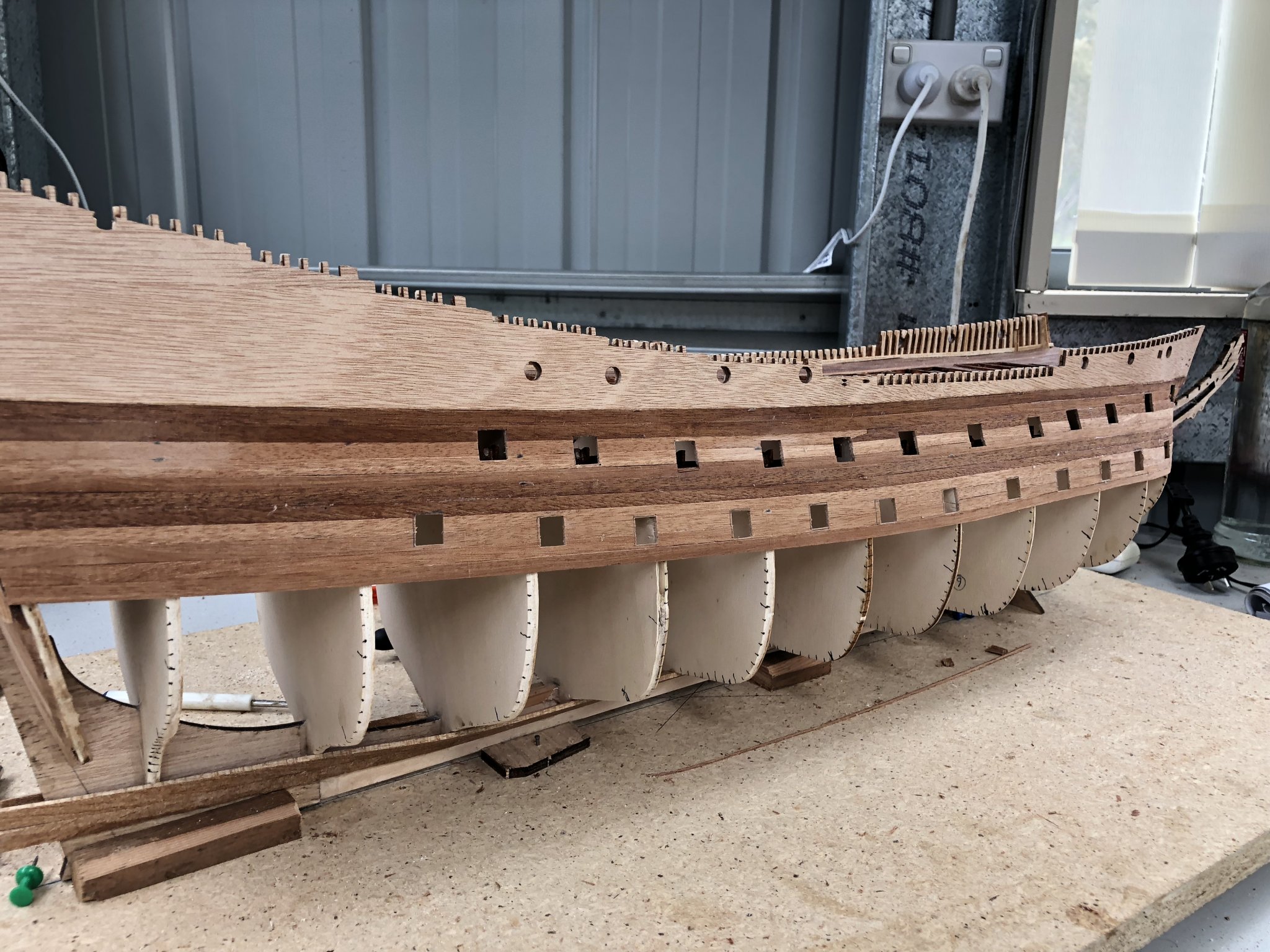
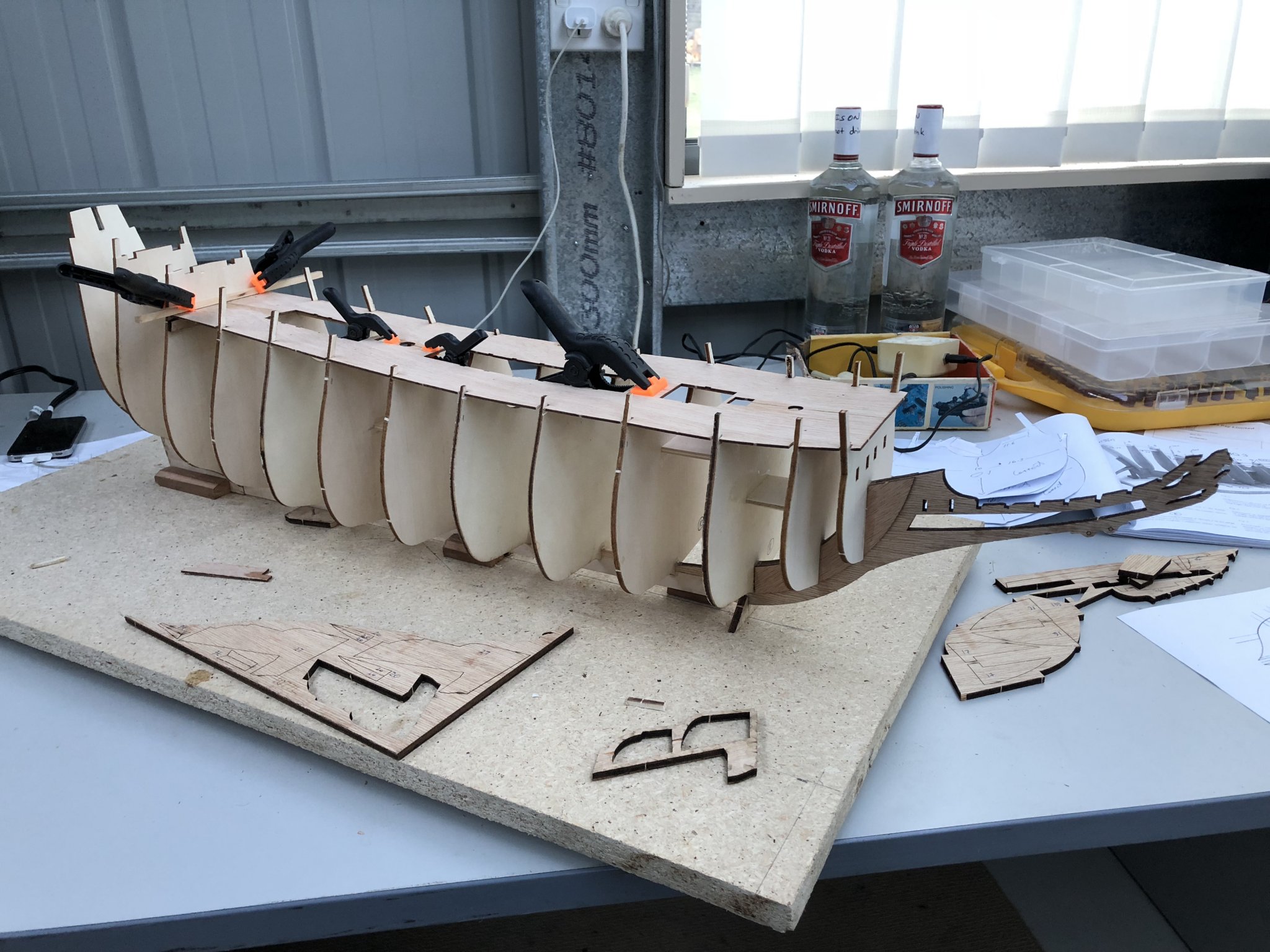
The planking (my fears are always with this stage!!!) has now commenced in earnest!!! I started the planking from the topsides towards the keel. The upper most section was not too bad as the curvature shape at the bow and stern were relatively mild and so the mahogany strip timber with soaking in hot water for a few minutes, seemed to bend without too much trouble. Shaping of each plank was done initially, according to the width marks on the hull, and after a few planks were added, it started to progress quite well. It then became time to allow for the gun ports. On the Vasa, beneath the weather deck guns, are two additional levels. How to position these? On the Billing Boat kit, is supplied a series (86 I think), plastic 'inserts' for the gunports and within these are the 'half' cannons supplied in brass. These cannon barrels are a stub, false cannon designed to push fit into timber within the cannon locations behind the ports. No information is provided in the instructions as to how to fit these. Well, I was not happy about the plastic cannon port surrounds, and I realised I would have to construct some internal mounting and simulated gun carriages for the brass below-deck cannon barrels. The picture below indicates how I located the positions of the various cannon ports. From the instruction plans of the hull, I created an overlay of some clear plastic and used some fixed points (such as the weather deck upper cannon ports and breaks in the deck line to locate the overlay on the outside of the partially planked hull. I used masking tape to fix the overlay to the upper parts of the ship so I could roll it on and off the hull planking for marking the port positions for cutting out. At this stage the planking was down to about the first level of below-deck cannon ports (6 planks in the picture below. With the cannon ports drawn on the hull planking, I then used a piece of bent steel (actually roofing material called Colourbond in Australia), which I had punched out the precise size for the cannon ports. I then drilled around the perimeter of the ports and cut out with a sharp knife and then filed square. These came out quite well and in the correct locations. Where a bulkhead was encountered as I removed the port plank section, I also had to cut some bulkhead timber to allow for the cannon support timber to be positioned. These timbers involved making a 'floor' for the deck, gluing between the adjacent bulkheads and then inserting a false gun carriage to support the false cannon barrel. Each gun carriage was painted and inserted and glued into position. From the outside it looks OK and provides the support for the guns well. As the planking progressed, the gunports were eventually completed and it formed a good solid hull. I had to be careful with the planking as there is only a single planking used by Billings. while this is alright, it leaves little room for error if a mistake is made. Below is a picture of the planking on the starboard side with most of the gunports cut out. Similarly on the port side. You will note that there is quite a lot of variation in the mahogany planking colour along the hull. I tried to position planking and plank selection randomly but it has occurred that the lighter coloured sections appear where the gunports are. This was not by design as the gunport locations do not follow the line of the plank edges anyway. Nevertheless the finish I think will look OK when painted. I am not intending to use a stain, as I quite like the look of the mahogany anyway. The side gunwales still to be added will also be in black and these will add contrast that should look good. If necessary, I can also stain later when I see the overall hull's finished planking. For all planking I am using PVA white glue and then after each plank is attached I, go over the bulkhead-plank joints on the inside (where and while I can still access them), and add additional glue. At this stage I have used no nails, only glue and pressure for bending, plus I am pleased that as the planking proceeds, no stealers to fill gaps have been required. More soon... Peter G.


- 61 replies
-
- 6
-
-
- billing boats
- vasa
- (and 1 more)
-
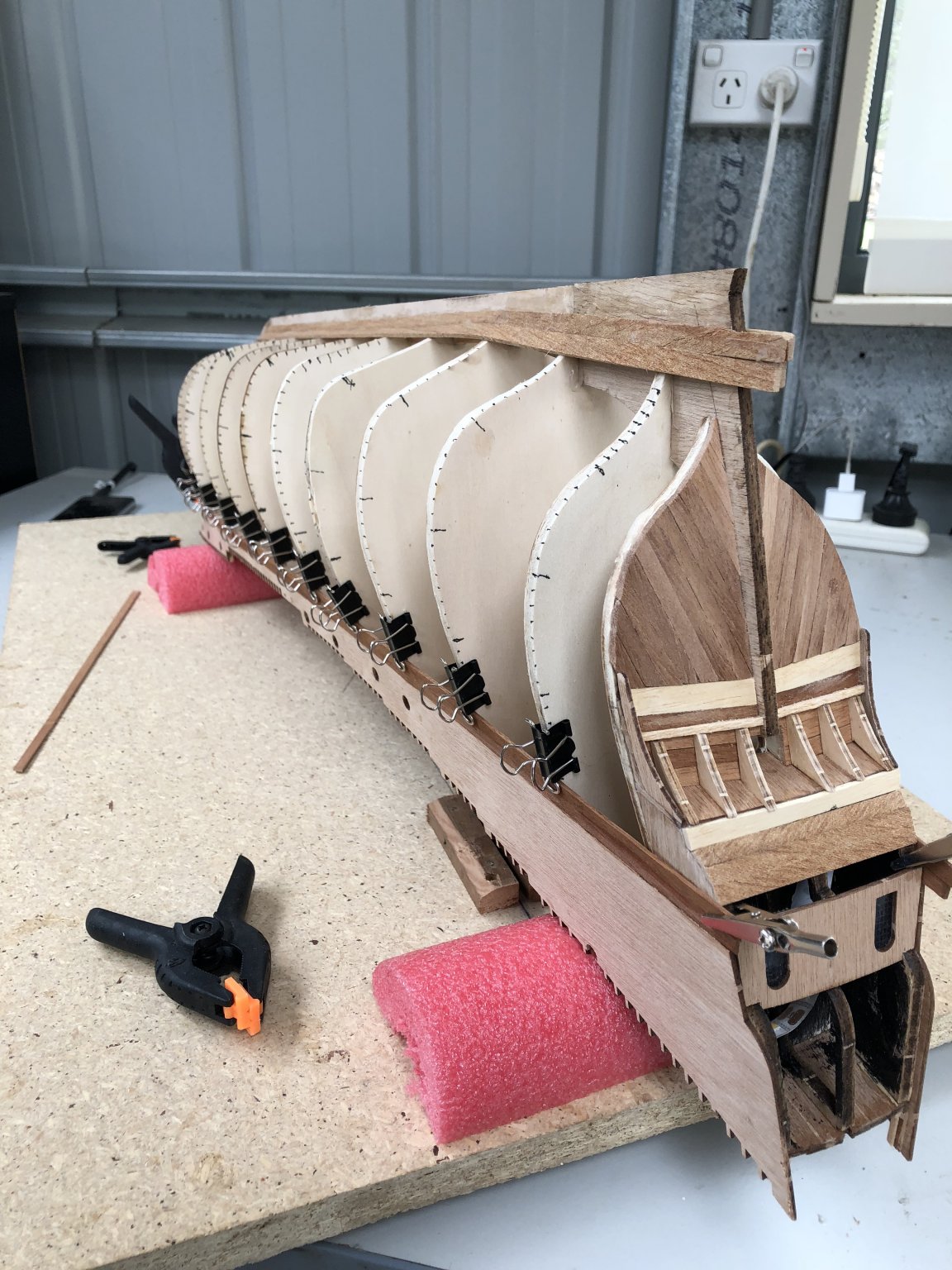
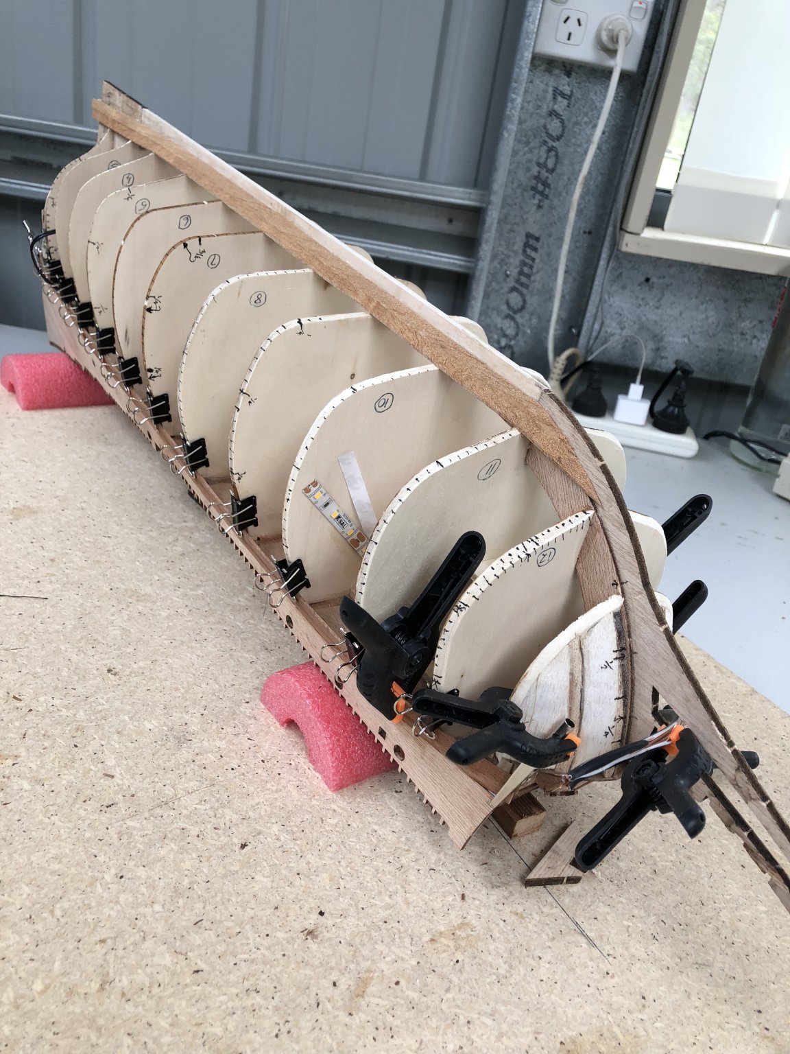
Further work on the stern area before laying out of the planking. The picture below shows the rear Captain's Cabin windows (with internal lead-light hatching), plus the completed but untrimmed rear planking. Using the dockyard base, I inverted the hull and laid out the planking for each bulkhead. This laying out follows the procedure outlined by a number of video and documents where the hull bulkhead lengths are measured, divided by the number of required planks, and then each bulkhead is measured and marked for the individual plank width. The planks are then shaped with the appropriate widths and fitted accordingly. A really good description of this technique is available from a search of 'lining off your hull for planking'. On the Vasa, the picture below shows how I lined it off. In the end I had no stealers and the planking went well, which I attribute to the marking and preparation. Note in the lining off above, the distances measured are between a top and bottom, keel planks already mounted and fixed. I used modified paper clamps to hold my planking onto the bulkheads during gluing. These worked well and I felt better than some of the commercially available clamps. The only problem with these comes late in the planking when the space available for them against the bulkhead becomes reduced. More later....


- 61 replies
-
- 6
-
-
- billing boats
- vasa
- (and 1 more)
-
Many thanks for the links md1400cs. I was aware of these sites and in particular the Clayton build. His awesome detail, especially when I get to rigging will be a great help. I am also endeavouring to finish the sculptures as you have done with the excellent painting and detail. I have some experience using Vallejo paints and so will be using these with highlight washes over a sprayed, white colour flat prime coat. Hopefully this will not mask too much detail. I have already done some experimenting with the shaping/bending of some sculptures and have been having reasonable success with a temperature controlled soldering iron. I am however interested in other people’s comments on their successes or failures in this area of shaping the Billing plastic sculptures.
- 61 replies
-
- 1
-
-
- billing boats
- vasa
- (and 1 more)
-
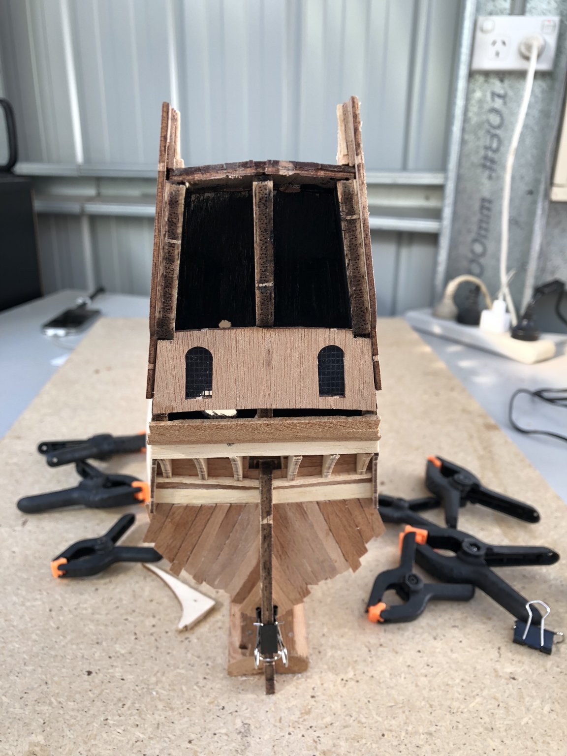
Having completed the ribbing along the upper decks and added the cannon ports to the weather decks, I then turned to the stern. In the picture below, you can see the ports and the shaping and bevelling of the bulkheads to accept the planking. Note too at the bow of the ship, I have shaped and glued in some balsa filler blocks. The purpose of these is to maximise the contact surface area of the forward planks which will wrap around the bow. The plank bending will be quite tight and so maximum gluable area will be necessary. The ship shape and hull designed by Billing's appears quite good. In the stern, I commenced planking of the angled stern timbers and across some of the bases of the stern extensions. I extended the length of the timbers beyond the estimated location of the hull planks which will be added soon. This meant that I could get a good 'butted' fit between the hull planks and the stern planks. I also added the rear lining with the two main stern windows of the Captain's Cabin. These I wanted to have simulate the lead light cross-hashing of the glass of the original ship, so I laminated the supplied clear acetate sheet (cut to size) with some fly-screen mesh obtained from a hardware store. I used CA glue for this and it seemed to work well. I painted the internal walls of the cabin black and with the LED lighting shining through, it is very effective (in the dark).

- 61 replies
-
- 6
-
-
- billing boats
- vasa
- (and 1 more)
-
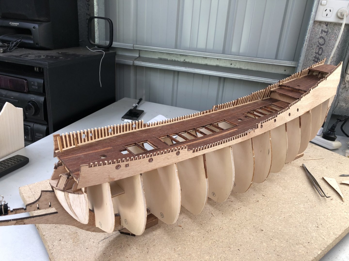
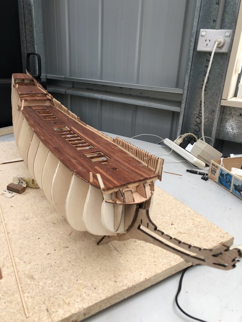
With the decking completed, I commenced the upper deck side panels and on the inside of these, I lined with mahogany and then began the 'false' rib extensions. I did these in obechi timber(as per the instructions). This timber is relatively soft and easy to work/shape but it is also a lighter colour to provide contrast with the darker decking timbers. I started on the port side for no good reason. As I progressed along the length of the hull, from the plans, I also cut out and shaped the weather deck cannon ports. These I drilled with a small bit to outline the hole, then cut with a sharp blade and filed smooth to circular. In the build of Nazgul (Matti), he used lighting in the hull for effect. I was tempted to do this also and so, at this stage, while the ship and hull were open, I cut some holed through the bulkheads in the rear (where there was no forward access. The picture below shows the hole in the rear bulkhead (No. 1) as well as the ribbing now completed on both sides of the inner deck area. This hole allowed me access to pass LED lighting into the hull and because of the lowered shape of the forward bulkheads, I could pass the lighting strip all the way to the bow. The voltage used was 12V and so required an external transformer. I have routed the wiring through a channel in the stern which will then come out through planking near the keel at the back of the ship. The outer deck linings where now completed to take the upper, overlapping (clinker) style lapped planks of the ship. I also noted the trimming of the shape of the bottom of this base, lining plywood (as discussed in depth by Mark (mar3kl)) in his build log. Mark observed that the shape of the bottom of this lining deviated significantly with the shape of the deck, and consequently the bend and shape of the outer planking as this lining forms the upper shape for the outboard planks. By trimming the base to match the deck shape, the planks from the upper to lower portions of the hull are then correctly placed. I think Billings have shaped the plywood as they have done for strength rather than accuracy, but I felt Mark's approach was good and so have adopted it here. Where there was some movement of the upper lining in the central part of the deck/hull length, I added extensions to the bulkhead ribbing and drilled this into the bulkheads below. With gluing (PVA), this appeared to provide sufficient strength and removed any movement.

- 61 replies
-
- 5
-
-
- billing boats
- vasa
- (and 1 more)
-
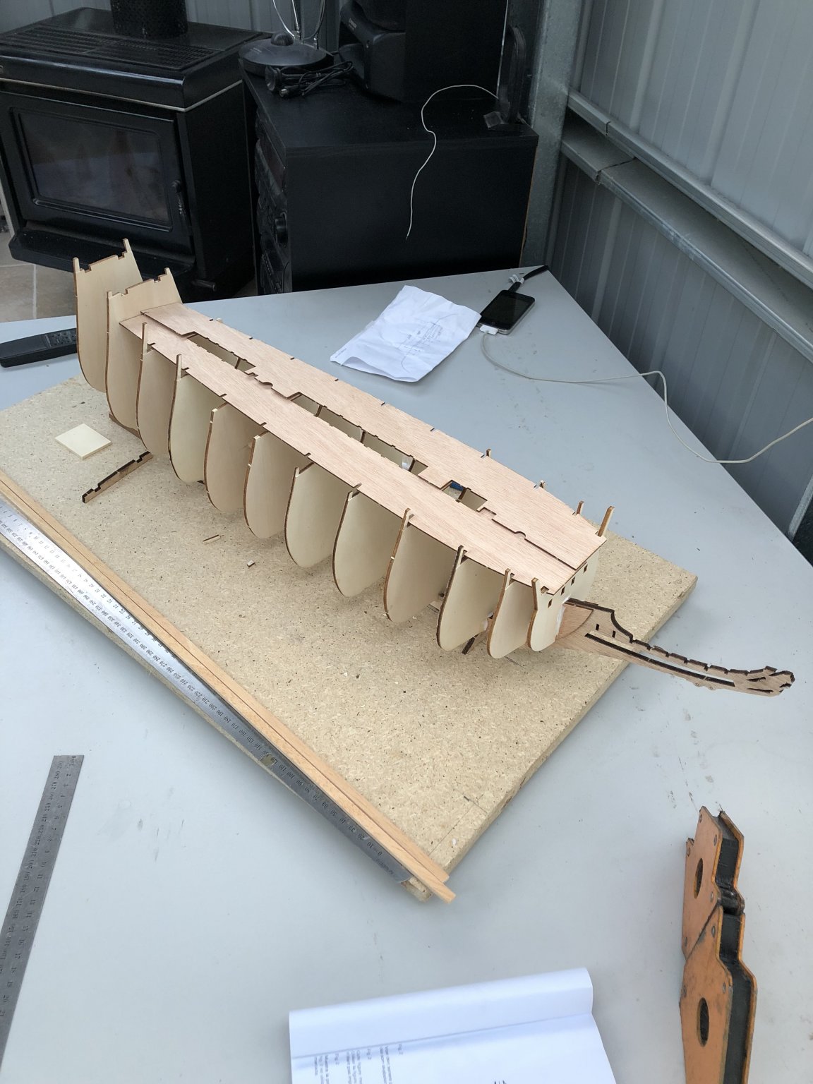
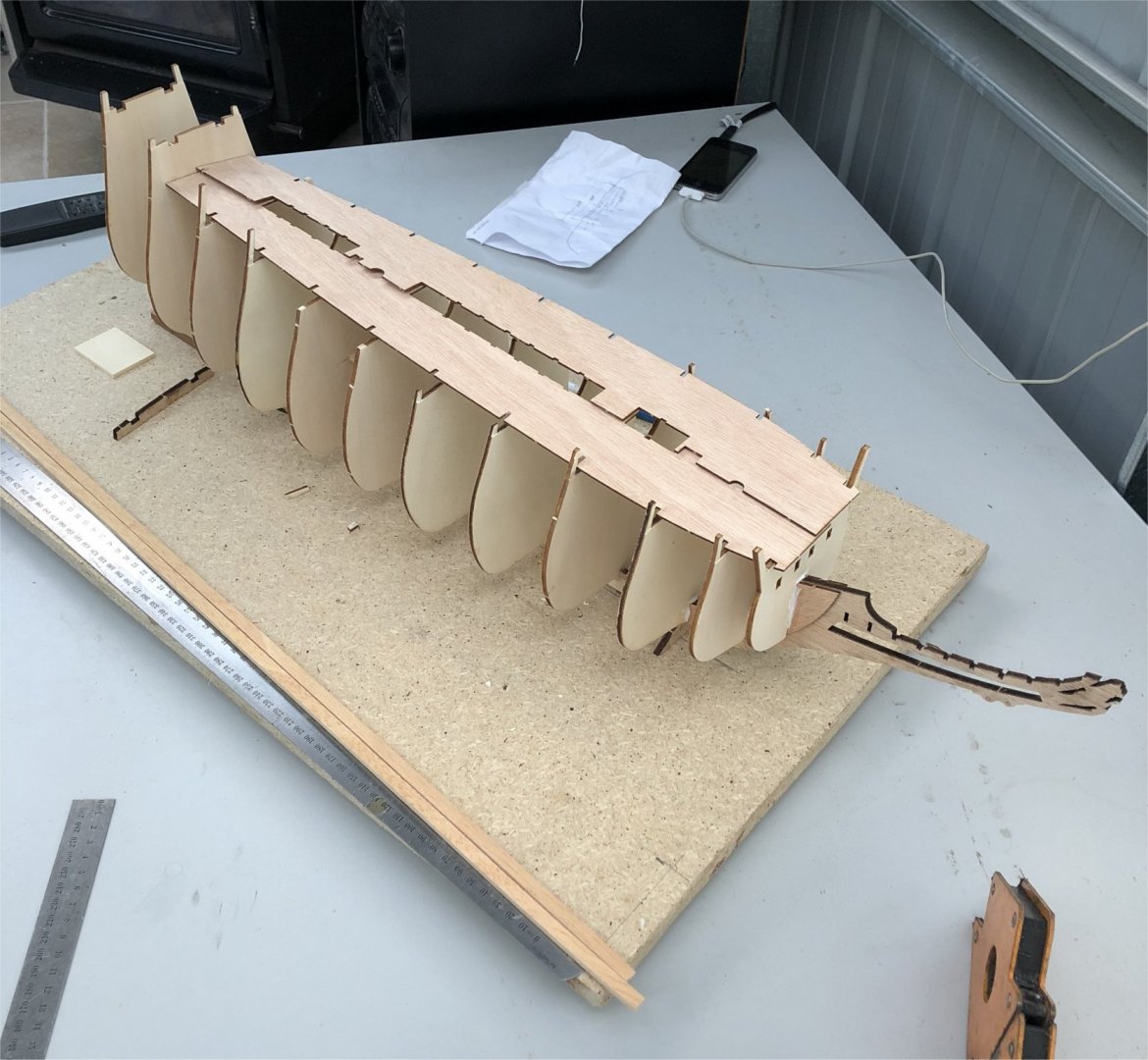
I have developed a workshop specifically for building the Vasa (much to my wife's amusement) with a small power bench saw, lathe and various vices. I find a good stereo music system also a must as background. In the pictures posted, you will also notice a flat piece of timber on which the framework sits. This 'dockyard' I have designed with two things in mind: 1. The support for the growing ship can be rotated along a horizontal axis, even supported upside down, using soft plastic rubber (as used by swimming pool flotation). This will enable me to place the hull into the best position to plank, add fixtures, scupltures etc. 2. Another innovation is that the base board is mounted on a large circular, metal ring with ball bearings (online they are referred to as 'lazy susans platter or bearings'). These are cheap and easily fitted to a base. This allows complete 360 degree rotation simply and effectively. I have found this to be a wonderful means of accessing the ship all around, quickly and with care, safely. A note of caution with this however. Sometimes the rotation is so free, that a part of the ship may extend over the work bench. When this is the case (as for example the bow extension), it can easily be caught by a moving arm or clothing. After one disaster where I caught the bow, I soon became aware of this shortcoming. The ease of access to the overall ship however makes this innovation well worth it. Following the bulkhead placement and the deck base, I commenced with the decking. For this and after some research, I noted that there was no geometric or logical layout to the placement of deck planks on the actual ship. They were seemingly random, and so I adopted this for my model. The planking I used was of mahogany but of a size scaled to be between 10 and 12 inches width (254 to 305 mm). I laid these using caulking simulated by PVA gluing one side of each deck plank with black crepe paper. When dry, I trimmed the paper and sanded the plank flat before laying it down on the deck base. I commenced from the centre and worked outwards to the hull flanks. Allowances had to be made for the hatchs and stained timber edging was added to get the dimensions correct. The hatches themselves, with the Billing kitcame as a series of laser cut plywood cutouts. These with some work to weather and scribe the individual vertical/horizontal hatch timers looked and fitted quite satisfactorily. Final treatment of the decking was by using a 'burnishing' organic oil. This finish is quite hard and durable when dry and leaves a lovely patina on the mahogany. The caulking with the black crepe paper stands out and looks about in scale. In the picture above too, I have shaped the edges of the bulkheads to the required angles to maximise contact with the hull planking around the curves of the hull. This Billing model requires a SINGLE planking only and so the glued and fixed contact must be strong and capable of maintaining the timber curves required with minimal splitting or gaps between planks. The doors fitted above the beak area for seamen's access I have simply scribed the laser cut plywood and run black ink into the lines using a Rotring drafting pen. My Rotring pen set got a working out on this model as I discuss later.

- 61 replies
-
- 9
-
-
- billing boats
- vasa
- (and 1 more)
-
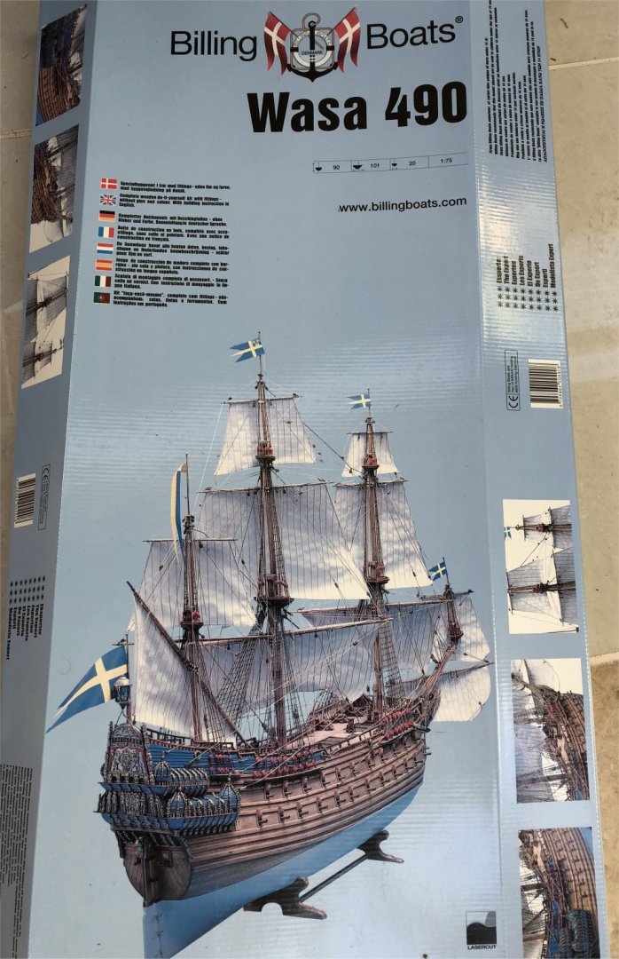
Hi, My name is Peter, and I live in the snow country of south-east Australia (yes we do have snow in parts of Australia during winter!!!). About 12 months ago, following an inspirational cruise in the Baltic Sea and a visit to the Vasamuseet in Stockholm, I commenced building the Billing Boat's Vasa. This is the second large Billing Boat I have constructed, the first being the Cutty Sark, almost 40 years ago. This model is proudly displayed in a glass case in our home and has been a talking point and feature most of my life. Hopefully, while I now have more time, the Vasa will be the same. I have read many of the build logs regarding the Vasa by Nazgul, Marketdiens, fmodajr, md1400cs, mar3kl, Karleop and others. These builds are a mix of Corel, Sergal/Mantua, Billing and more recently the De Agostini release from Italy. Prior the DeAgostini model (by ModelSpace), a number of writers commented that they felt the Billing Boat's Vasa was the most accurate, and it was available before the DeAgostini model release, and so my choice was the Billing Boats kit. Having now progressed through this build, overall I am reasonably happy with the content of materials (although I have substituted some timbers), and scratched a number of items (eg below decks cannon mounts etc). The instructions are limited and short on detail, but the build logs have subsequently helped and filled in some of the 'gaps'. In particular, the exquisite build of Matti (Nazgul) has been wonderful, but many of the ideas of Mark (mar3kl), I have also adopted. So, to begin, the packaging and delivered product was complete with no obvious broken parts or missing items, but these would be picked up as I went along in the build. One thing that I did notice however was that hull planking used timber referred to as 'Obechi'. While this was all included, I did not like its scaled width or thickness, and so I did some maths to scale the planking of the actual ship pictures I had, and then purchased some 5 x 1 mm mahogany in precut strips. This to me, was a much better planking material, and better for the scaling appearance of the ship. A similar argument held for the deck planking and so I milled some of the mahogany to use for this as well. Different stain/treatments were also used to maintain reasonable appearance and weathering effects. Bulkhead layout was straightforward but the bulkhead extensions above deck (which were instructed to be 'thinned') were weak and fragile. Some of these broke in the process of the build, especially with the deck plywood fitting and so I trimmed these and added extensions later when the planking was built up above the deck level. The decking base needed some trimming but this was minimal and fitted satisfactorily. Before any comments are made about the Smirnoff bottles in the background, these are holding raw alcohol which I intend to use in assisting the bending of planks. This is to be an experiment, but I have read where it is more effective than water and/or steam bending. More on this later!!


- 61 replies
-
- 6
-
-
- billing boats
- vasa
- (and 1 more)