HOLIDAY DONATION DRIVE - SUPPORT MSW - DO YOUR PART TO KEEP THIS GREAT FORUM GOING! (Only 53 donations so far out of 49,000 members - C'mon guys!)
×

Peter G
-
Posts
39 -
Joined
-
Last visited
Content Type
Profiles
Forums
Gallery
Events
Everything posted by Peter G
-
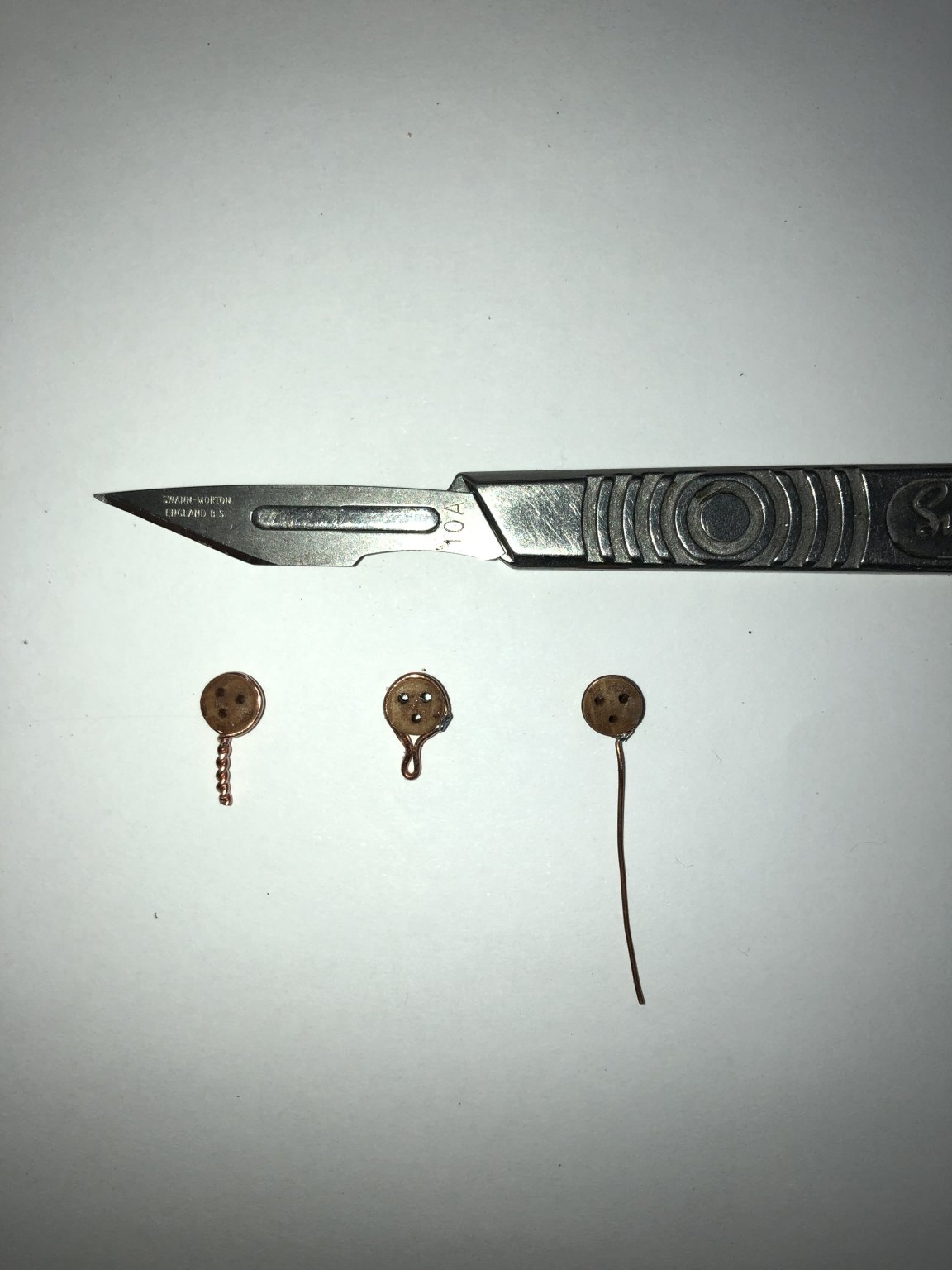
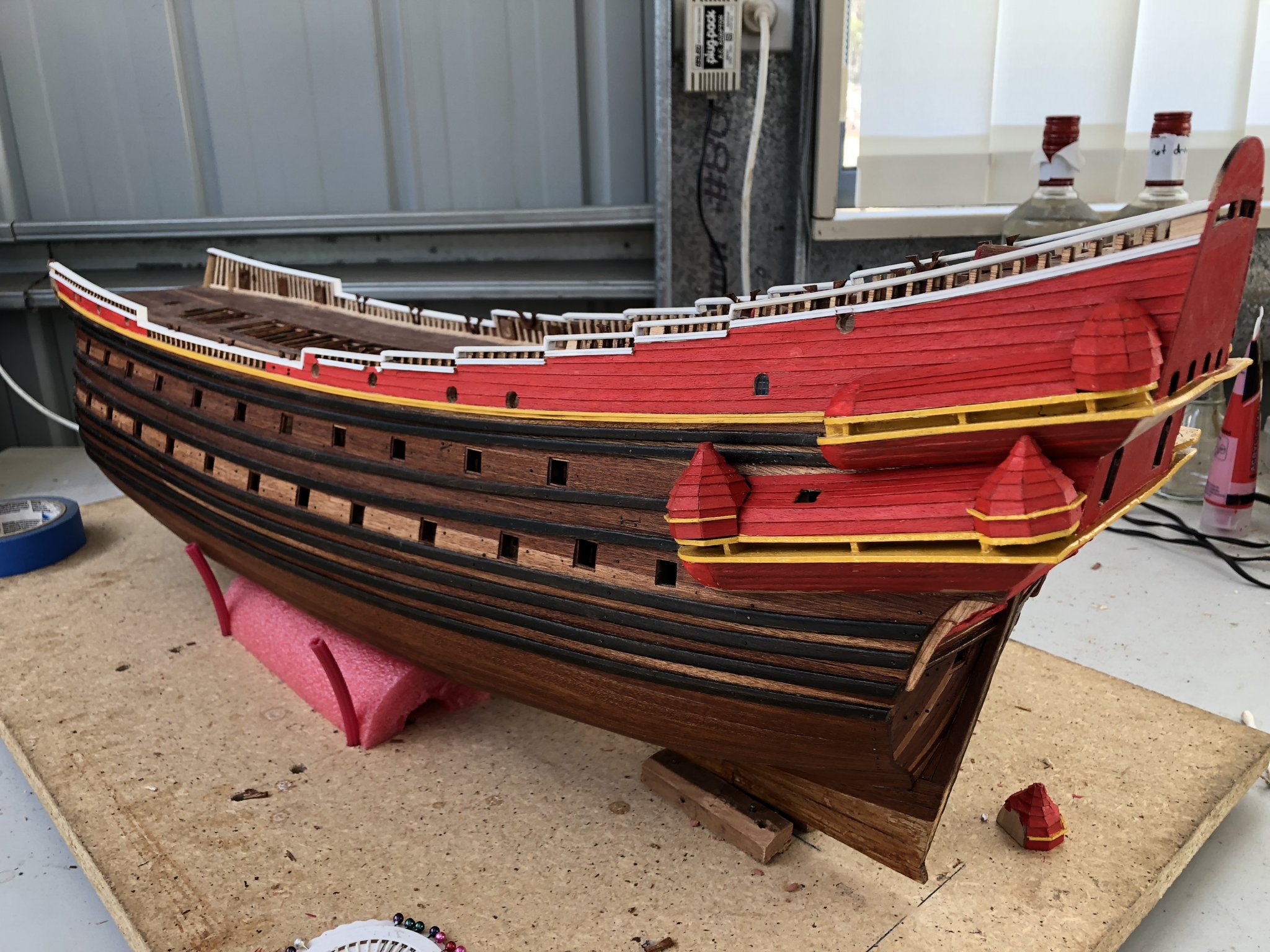
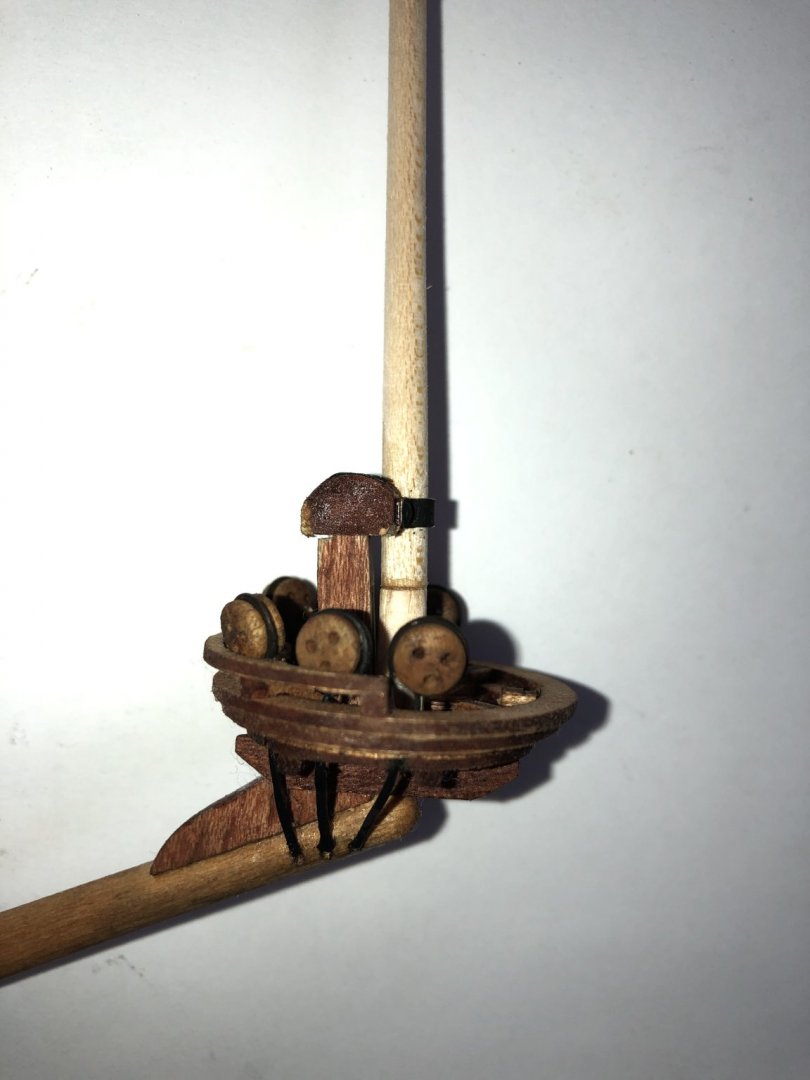
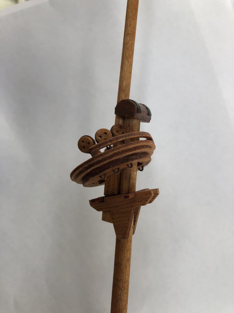
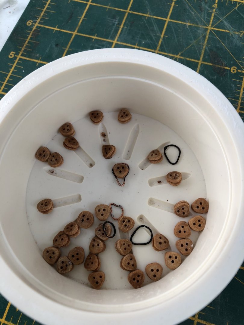
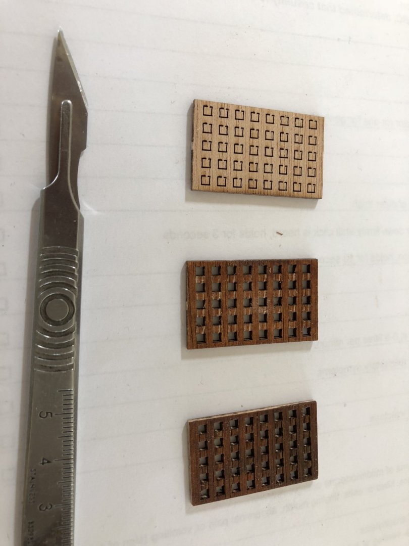
 I have been figuring out a way to mount and secure the deadeyes to the tops. The bowsprit is the most difficult as the strops continue through the base of the top to be secured into the timber of the bowsprit itself. There are three deadeyes each side and these have to be mounted at the same height above the top level on both port and starboard sides. So, I have read a few ideas as to how different modellers have secured these. Some of the methods involved, using 0.7mm copper wire around the deadeye and then twisting so the twist can be mounted into a drilled hole. This method I did not like as the twist is not authentic, it will be visible, and it is hard to use the twisted wire beneath the top as a strop or be bent to form an eye for ratlines below (in the case of the main, fore and mizzen mast lines). A second method is to use copper wire to form the same shape as used for the main chainplate deadeyes and then secure below by a line to the top. While this is more elegant and matches what I have already done for the chainplate deadeyes, it is not consistent with forming an eye beneath the tops of the other mast tops. The third and I think most practical method which I have adopted, is to wrap the deadeye with copper wire, then bend ONE end beneath the deadeye and solder to the other, single strand which is then extended below holes in the tops. These extended wire pieces are then easily bent into a loop, and secured back into the hole to form a loop, eyelet for rigging below the top. Below I show a picture of the three methods, with the extended wire method on the right. Although I like the above method with the wire extension, it does pose one problem (as applies to ALL the methods) - How do you get the strop blackened? If you blacken it (by painting or by copper blackening solution), then it is difficult to solder (without cleaning the wire parts to be joined). If you solder first, and then dip into copper blackening solution, what effect will it have on the wood of the deadeye? Well, I tried both methods, solder first and then dip into blackening solution, and blackening first and then clean to solder. The soldering first did indeed make the deadeye dark and with a 'dirty' look, so I was then left with the second method, which was slow and required only the required part of the wire to be cleaned with a scalpel before soldering - but it did work. OK, now I have my 40 required deadeyes for all the tops with wire strop extensions. In the case of the bowsprit however, the extensions were actually flattened 'bars' which continued down to the timber of the bowsprit and secured, rather than roped extensions. Hang on!! I am dealing with copper wire - Perfect for flattening!! So I simply laid six of the deadeye copper wire extensions onto a metal plate, and hammered them flat. A little black paint and Voila - Flat, metal strop extensions to be secured into the bowsprit timber. Below is the result. In the above, you can see the painted and flattened copper wire extensions below the top. Note too that I have not stained the spritsail mast section above this top yet, so it appears lighter in colour. With this top now nearly complete, I turned my attention to the other tops of the mainmast, foremast and mizzen. These tops can have their deadeyes added to the tops even before the masts are finished (so long as you don't glue and finish the various fittings of the masts which prevent the tops fitting over and down the mast sections to the final required location). As an example, in the case of the small mizzenmast top, below is a picture which shows the top, unsecured, but in its correct place. It is unglued but shows the deadeyes with their single wire extension, this time, not flattened, but bent to a loop which is then returned into the base wood of the top to form an eye. These eyes are then used to secure the ratline lines which extend from lower in the mast or ship deck levels. I will continue to complete all the deadeyes for the other tops and then work more on the masts themselves. Elapsed Time: 1495 Hours Regards, Peter G.
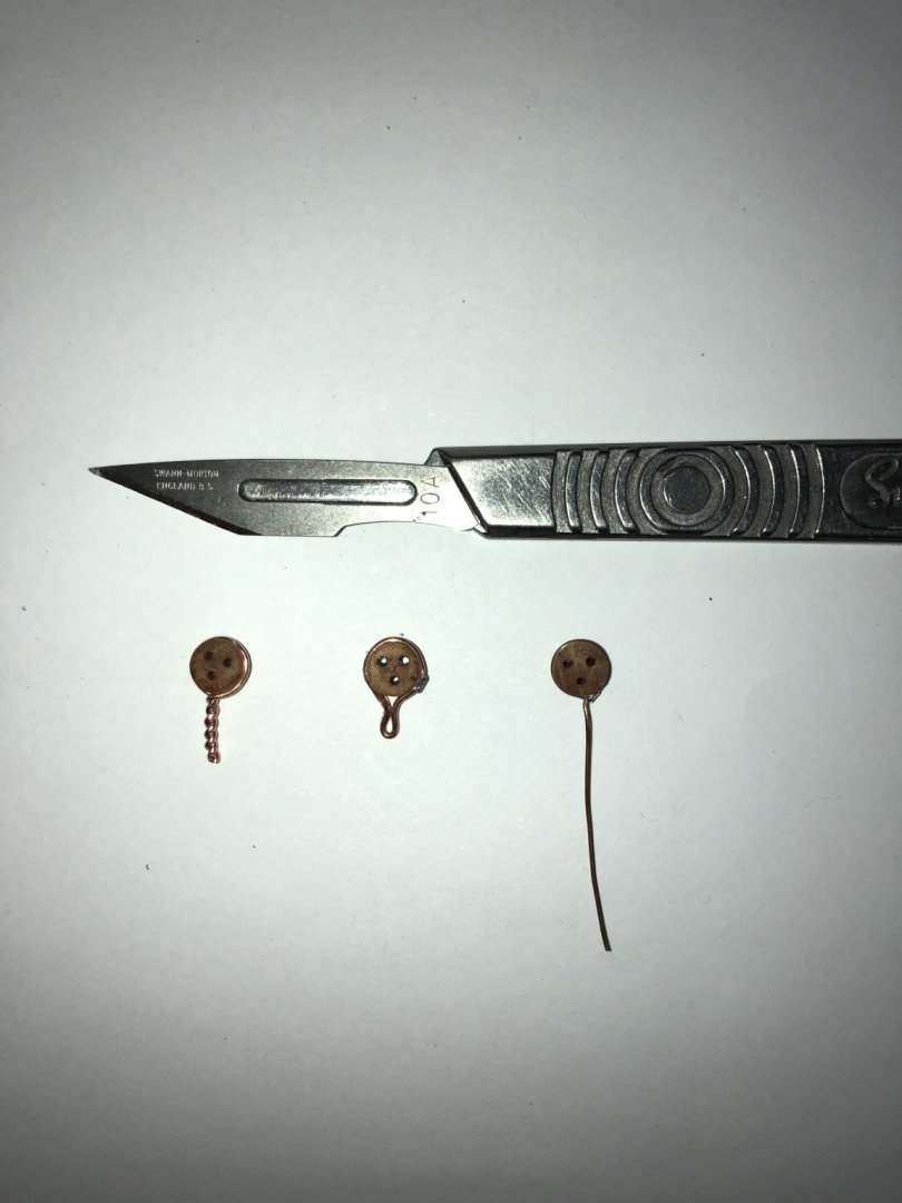
- 61 replies
-
- 5
-

-
- billing boats
- vasa
- (and 1 more)
-
Many thanks for the responses guys (Johnathon11. EJ, Michael (MD1200cs). Also many thanks to Michael for his input on the lathe. definately a better setup. Don't you find that the Dremel takes too much off in a small area along the length such that you find it difficult to result in a smoothly tapered length? I must say however, your result looks excellent. By the way Michael, I was reading your blog the other day about how you got your alias - From the early computer model. We must be a similar age!! To the other responders, this link and the advancements in VR will be a great step forward for the Vasa and its horde of modellers out there. I really look forward to getting great detail on some of the outside areas in particular, especially the galleries. Regards, Peter G.
- 61 replies
-
- 2
-
-
- billing boats
- vasa
- (and 1 more)
-
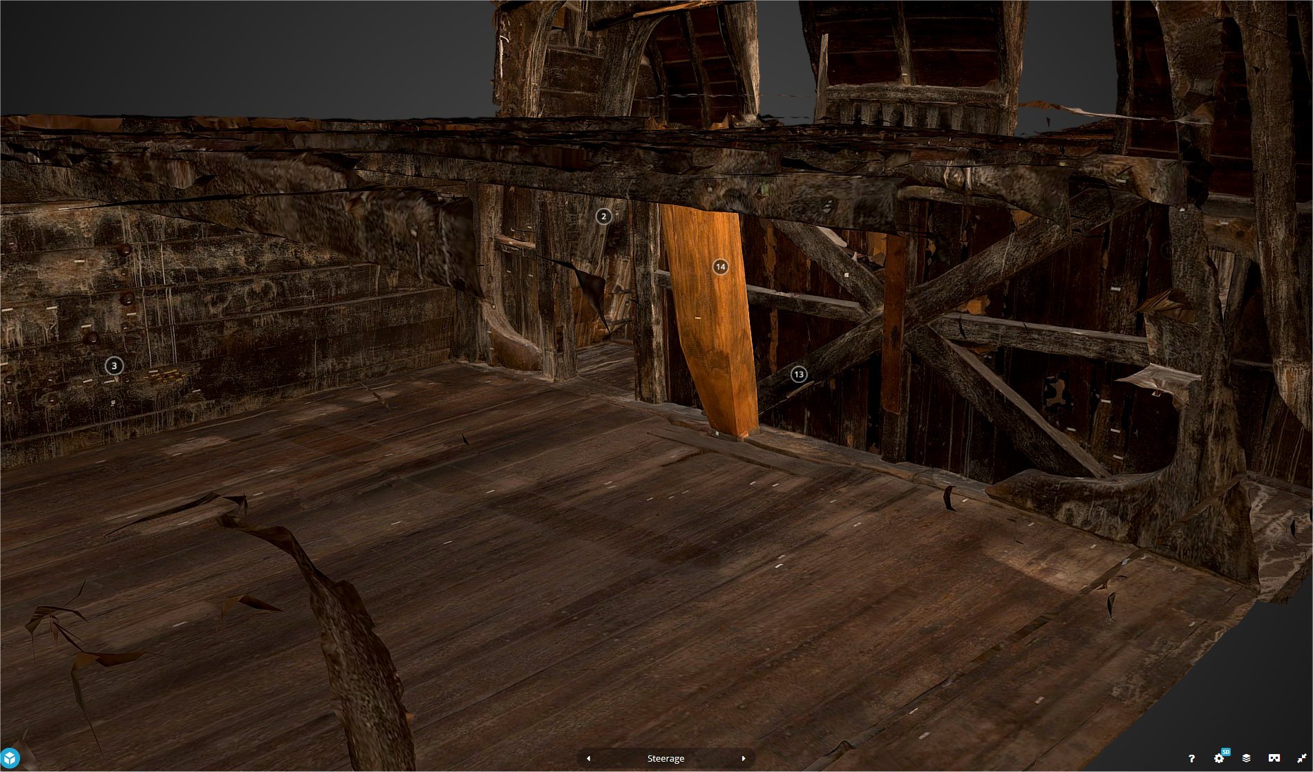
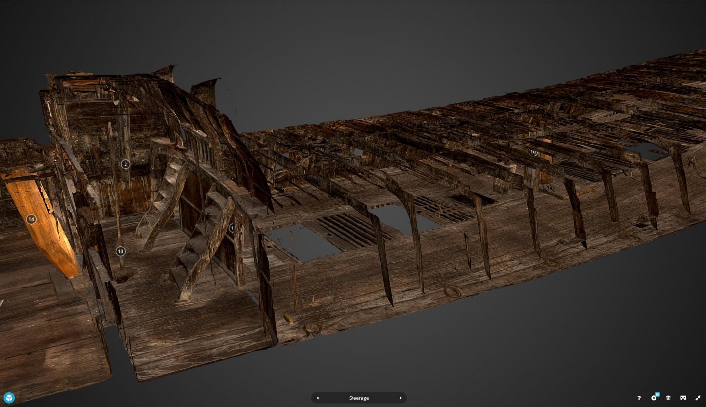
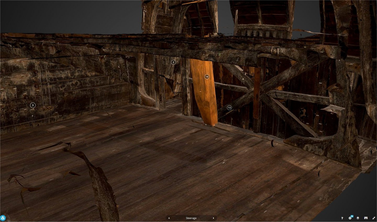
I'm excited!!! Came across a breakthrough website today. A little of the background..... A few posts ago, Maarten sent me some photographs of the Helmsman's cabin/loft forehead of the Great Cabin. This was excellent for showing me the 'slits' through which the helmsman received orders and could see to steer the ship. I was however a little curious as to what the helmsman would actually see, so I did a Google search on the topic and came across the most awesome website describing the work being done by Håkan Thorén who has been working for the Vasa museum in Stockholm for about two years. Håkan is an archaeologist but has recently been working on technical applications in archaeology like GIS, software development, total station surveying and laser scanning. In particular, Håkan has been working on a 3D Management Tool to provide a framework for 3D image rendering of the Vasa. His website describes the process, the cameras, images and their 3D GIS location such that for the main Gun Deck (the first level below the Main Deck), he provides a 3D interactive environment using SketchPad. For me, the Helmsman's Loft is totally visible and in VERY high detail. Below I show two pictures captured off the computer screen from the 3D SketchPad application. The first photo shows the Helmsman's Loft (to the left) with the Main Deck and Gun Deck stretching to the right. The second photo, I have rotated the view and zoomed in to show part of the Main Cabin and the location where the Mizzen Mast as it comes through the raised Weather Deck. The website to access this is located at: https://sketchfab.com/blogs/community/vasa-national-maritime-museum/ This development is a part of a Swedish National Maritime Museum's project. On the website are some images, but also the link to take you to the 3D rendering Sketchpad application for computer, smartphone or tablet. At present only the Gun Deck has been made available in 3D, but this shows the incredibly powerful scope of detail, navigation and views of the actual ship that can be obtained. In the future, the whole ship is intended to be made available. Within the 3D view too are isolated 'marker's that provide information and can be clicked on to take you to an optimal view, from stern to beak. As Håkan says, for the future: "The management tool is at the moment under development and is planned to be tested and ready for use in the near future. The completion of the (entire ship) 3D model will take a little bit longer. According to plan we will have a complete model of Vasa by the end of 2021 and we plan to continuously upload all parts to Sketchfab." I think this development could revolutionize the detail that could be made available in a ship such as the Vasa. This work is invaluable in providing those views and information so important to our modelling community. Another development underway, is to use the Management Tool to permit access to 3D views of artefacts recovered from the ship. As there are over 20,000 of these, it would be a massive job, but even to get on board a 'virtual Vasa' would be of immense assistance to modellers all over the world. I hope you find this as interesting as I have, Regards, Peter G.
- 61 replies
-
- 5
-
-
- billing boats
- vasa
- (and 1 more)
-
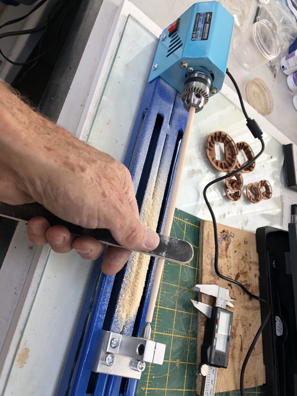
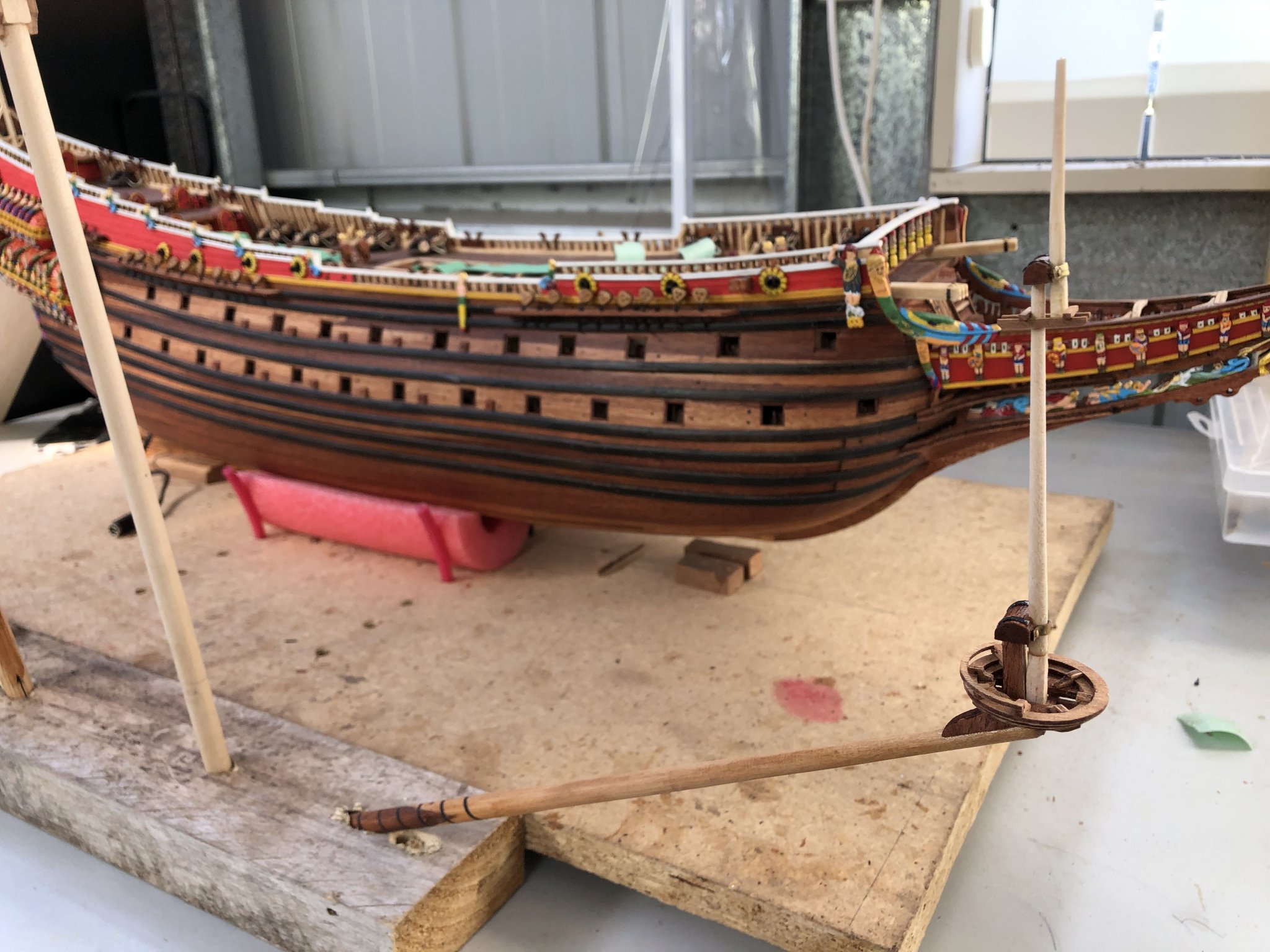
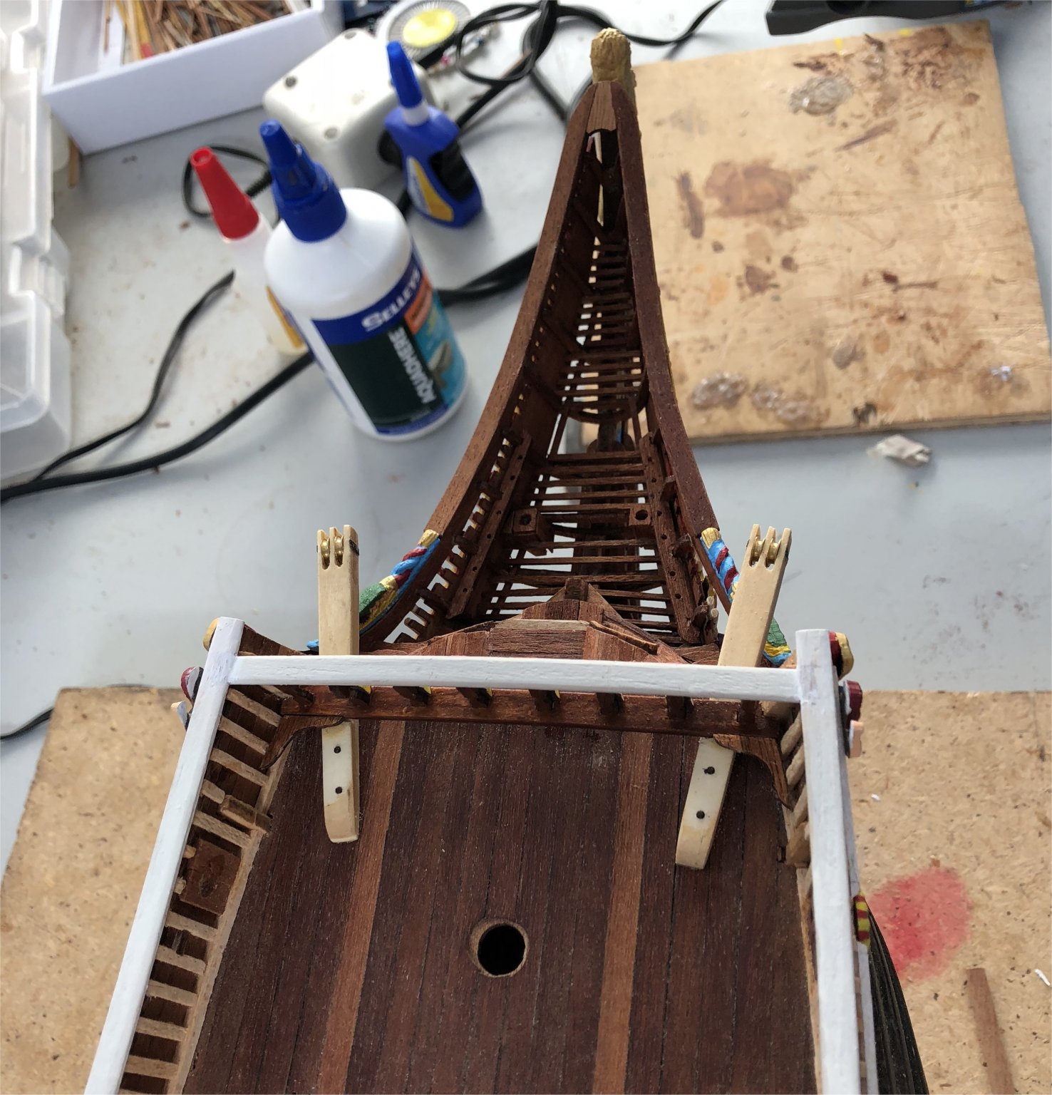
Many thanks Johnathon and E.J. Always appreciate the comments.... I am commencing work on the spars, masts and bowsprit etc. With the tops finished, this is the next logical stage. I thought I would start with the bowsprit and the steps to be followed are: 1. Identify the timber (quite an exercise as there are a number of diameters, lengths and timber types for the 3 masts, mast sections and spars plus bowsprit). 2. Take the bowsprit timber and shape it to have a taper as instructed. I used a small lathe I have to do this. It was cheap and I have transferred the motor drive to a much longer slide to allow the mast lengths to be sanded. I can set the centre points of the wood and lock it between the slide points and then sand it accurately. The lathe is shown below. 3. With the bowsprit tapered, I then needed to scribe the sides with the back of a sharp blade (using a technique that follows a straight length of stick-on Dymo tape. The blade follows the tape shape and allows the hull entry end of the spar to have four scribe marks along its length that then come together. The area scribed was then stained to indicate a different wood used as if the bowsprit were 'laminated' from different timbers as on the real ship. 4. Once the staining and bowsprit timber was finished, I then wrapped white glue impregnated, thin black paper around it near its base from about 1/3 along, to simulate the iron banding on the original ship. 5. Cut out the laser-cut plywood 'knee' at the front of the bowsprit and attach. This was to then have crosstrees fitted and one of the small tops. 6. Above the tops the spritsail mast sections are added. Below is a photo of the developing bowsprit. The next items will include staining the mast sections plus the addition of deadeyes and blocks. I am keen to get as much added to the masts/bowsprit as possible before actually attaching to the ship. I have ensured that the masts etc fit appropriately in the ship and when this is done, it should be a relatively easy job. Elapsed Time: 1470 Hours Regards, Peter G. PS Still have no information on how to rotate an image on the website when it loads at 90 degrees (see image two above) from what I see on my computer. If someone could advise how this is done I would be eternally grateful!!

- 61 replies
-
- 4
-
-
- billing boats
- vasa
- (and 1 more)
-
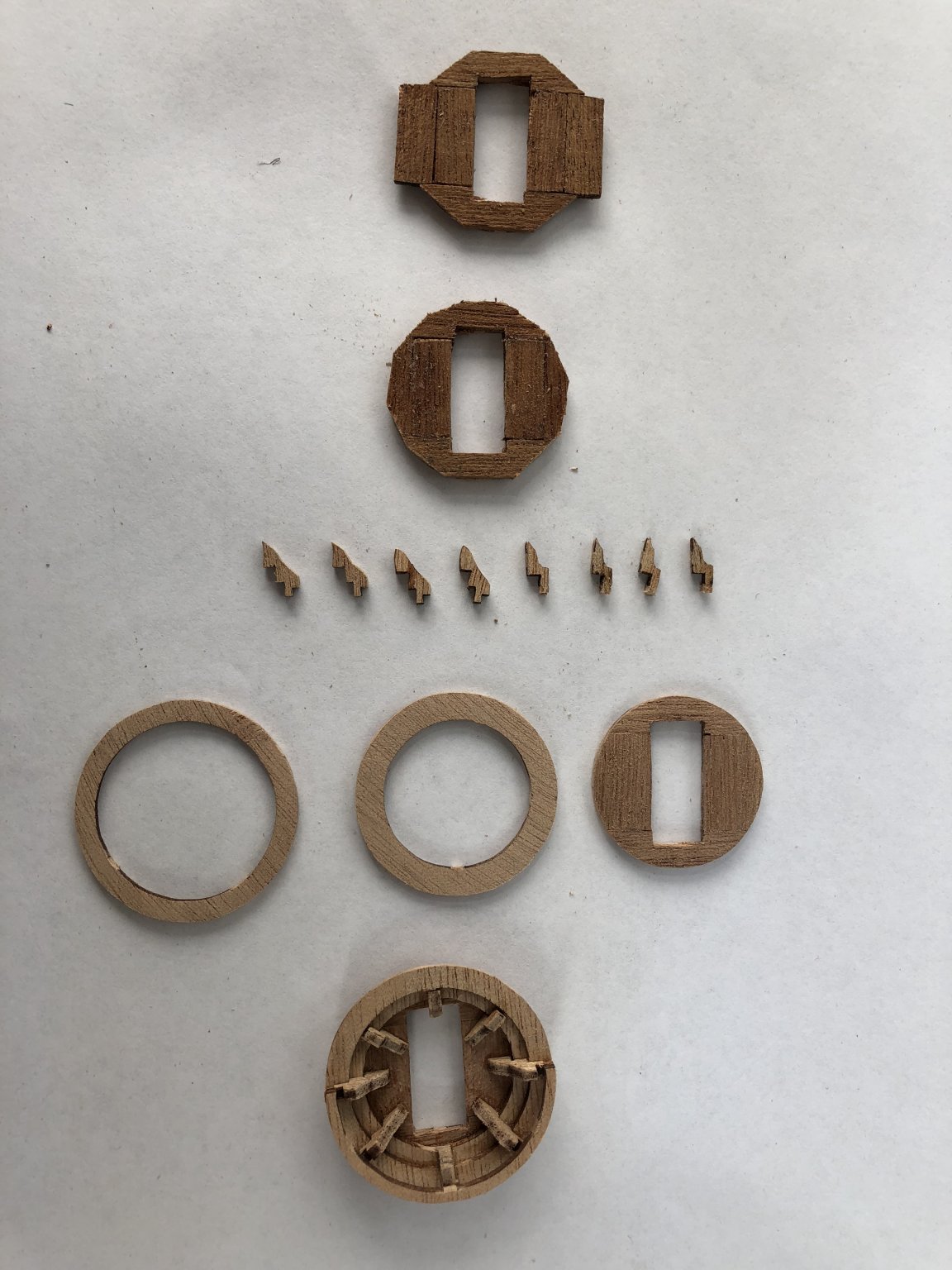
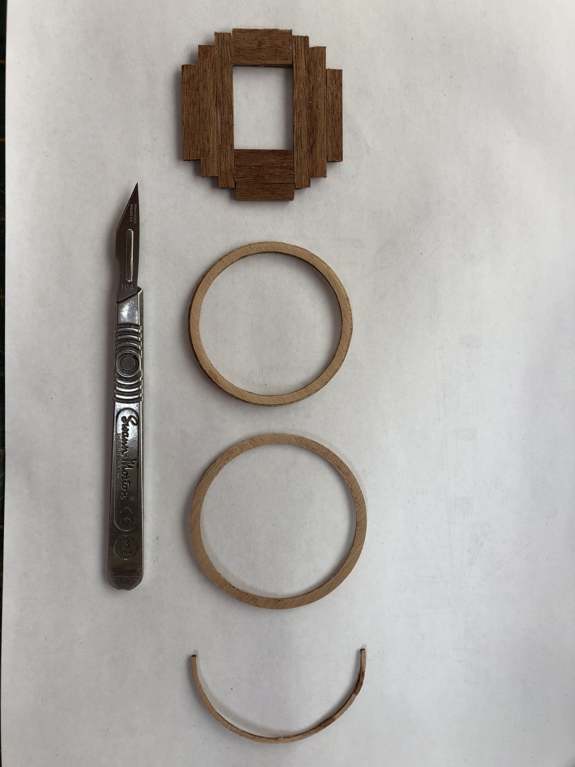
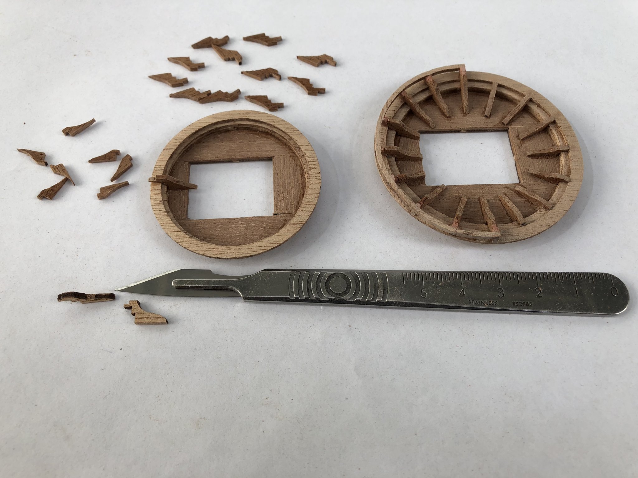
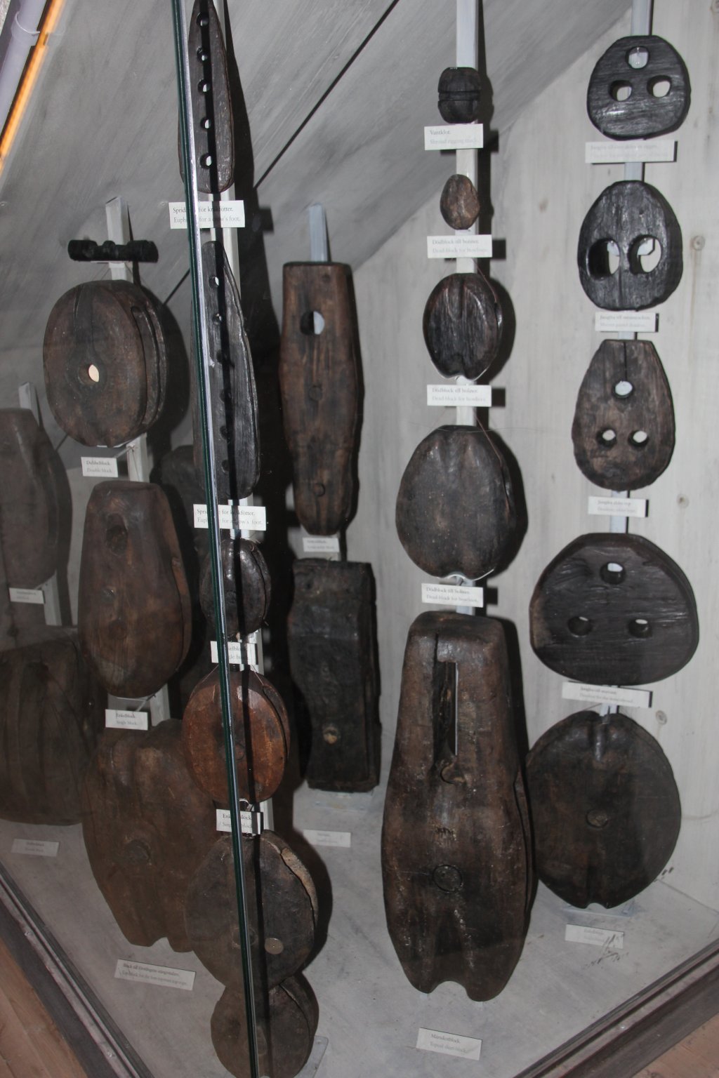
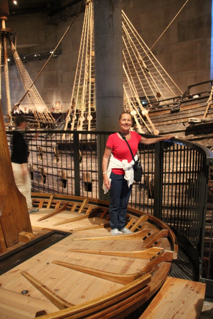
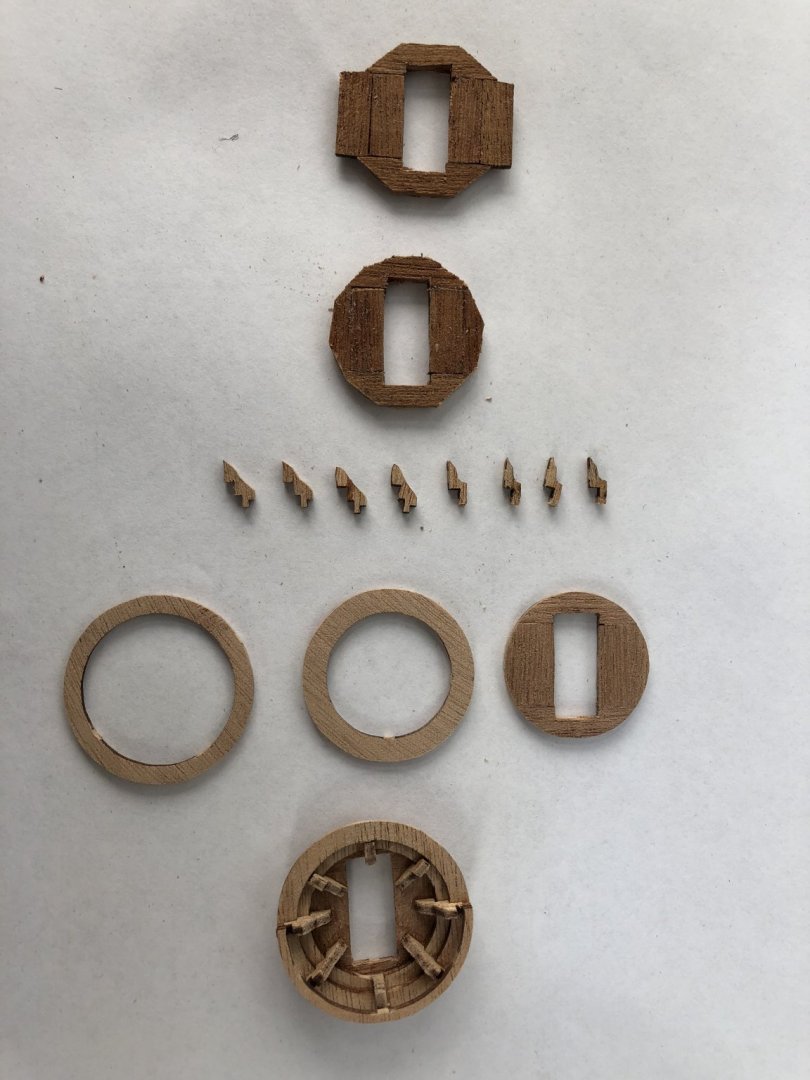
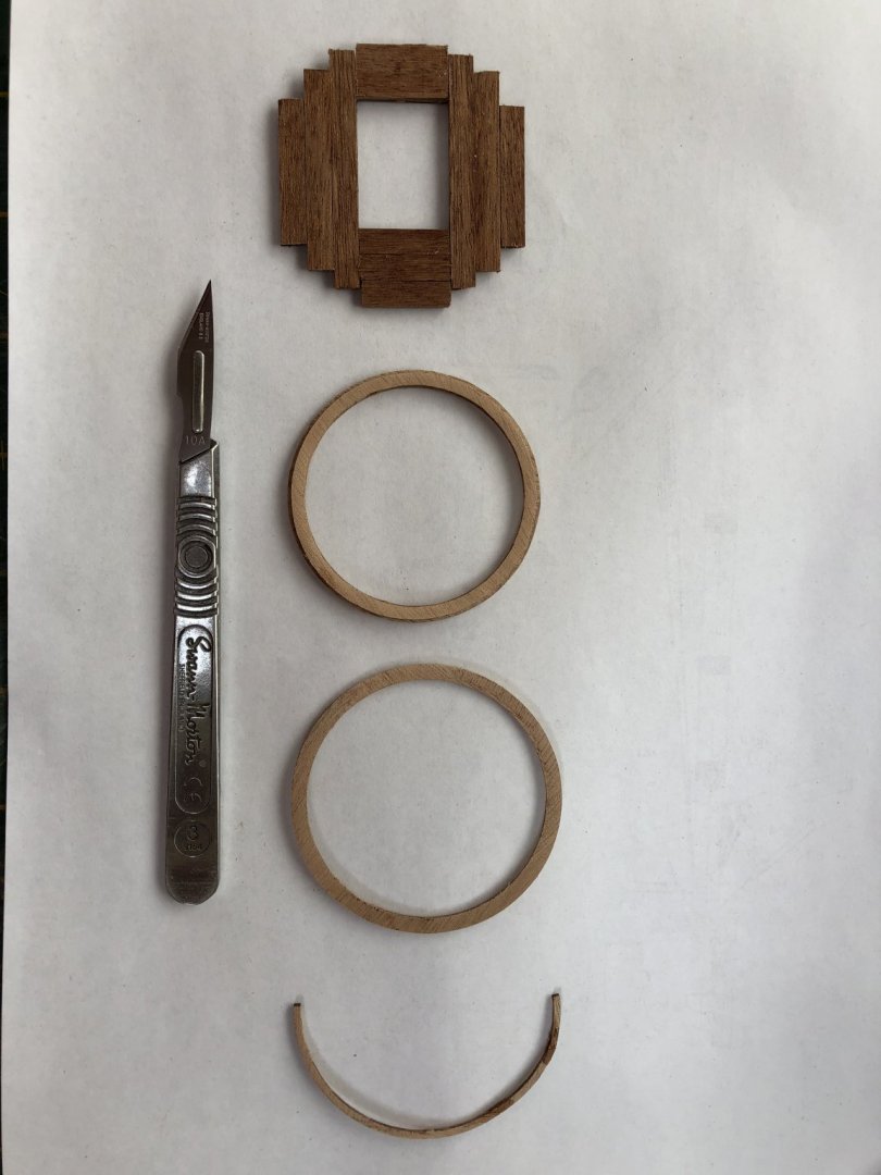
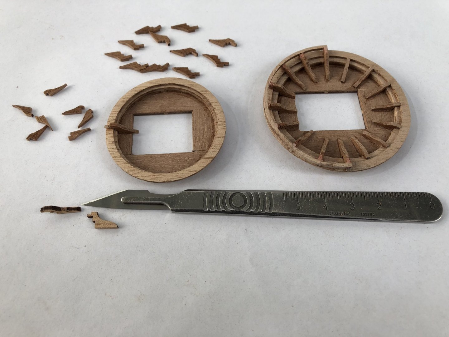
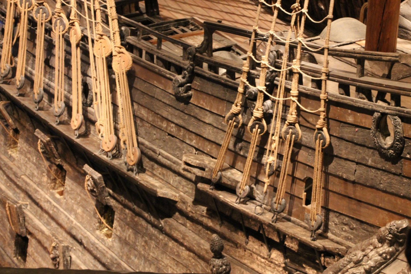
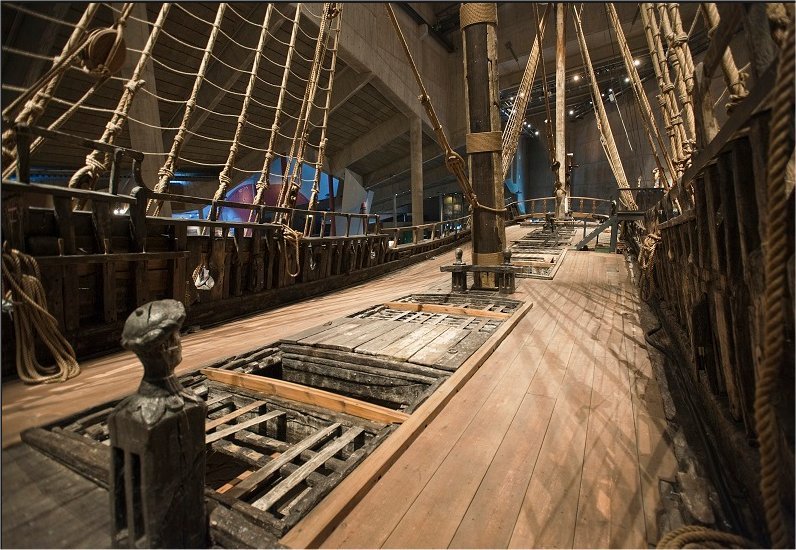
Next item on the agenda, the tops. The tops as provided in the Billing Boats kit come in three sizes - large for mainmast lower, medium for foremast lower and four identical small tops for higher main, fore and mizzen locations. These are provided as plywood laser cutouts including a series of 'rings' which are layered one on top of another to build the required height and with increasing diameters to give the size increase with height. The uppermost, half rings are particularly thin and narrow and subject to breaking if mishandled. I found that when I stacked the required three rings plywood rings onto the plywood base, the elevated height and resulting thickness was just too high and not in scale. If I dropped out the second ring (the same internal diameter as the third ring), and then sanded one plywood layer off (to result in two ply layers), the thickness and appearance was about right. I was also not happy with the appearance of the plywood timber on the base of the top, as it was not planked, as is the case on the real ship. A replica of the 'real' ship tops in Vasamuseet is shown below and you can actually walk on this and examine the way the tops were built (see below). The tops planking can clearly be seen on the base as well as the various staves/timber supports which radiate out from the inner base surface to support the elevated sides. In total, there are 16 of these, but in the BB kit, only a maximum of 12 were provided. The other thing about these radiating supports is that they are provided from the laser-cut plywood, so when cut out and sanded, their edges (which are uppermost), show the layering of the plywood, which I wasn't happy about. To address the issues above, for each of the tops, I did the following: 1. I sanded each plywood base and ring significantly to reduce their thicknesses by about half (a lot of work). 2. I used the various sized internal support supports as templates and created my own with sharp knife and Dremel to shape the curved upper surfaces. I did this with mahogany planking which was about the correct thickness, but had to be shaped. I had to be selective about the grain of the plank to ensure the support did not crack or chip. 3. I increased the number of internal top supports to 16 on the mid and large tops and to 8 for the small tops. 4. For each increasing height ring of plywood, I sanded to half thickness to scale the overall tops thickness/height. Layering the top base was simple with planking glued to a thinned plywood circular shape. Once glued onto the base, the uneven, planked edge was cut and sanded to match the laser-cut plywood sized base. The photo below shows a small top. Four of these in total is required. Below is a picture of the basic components of one of the large sized tops. This shows the planked surface of the plywood base before sanding to round and fitting the tops rings. The next photo shows examples of tops in the process of being completed with a completed main top on the right. The various crafted internal supports of the top on the left are shown to increase the number to 16. With the tops completed, I am about to move on to the masts and spars. Time elapsed: 1460 hours Regards, Peter G.
- 61 replies
-
- 5
-
-
- billing boats
- vasa
- (and 1 more)
-
Hi Wiktor. I like your planking. You are taking time and when you think it could be better, you are correcting it (eg the stealers at the bow). The planking is hard to get right. It is made easier by double planking but it it still hard. Pictures of the actual ship help immensely. There are lots out there and a few of us have some we can provide as well. I also agree with you regarding the planking colour and the suggested painting in the Instruction manual. I MUCH prefer to see the stained product which you are using, as it shows the wood grain and the beauty of the timber. It is also much more authentic of the actual ship (as it is now in the museum). I especially like your plank jointing. You have done a great splicing, angled joint job. What are proposing to do regarding nailing? The many nails on the actual ship have a combination of iron and tree nails (and now, replacement nails for conservation), but they are a feature which is an important part of the ship's appearance. You look as though you have nearly finished the planking and it will be a big relief to have behind you. The result looks great, so congratulations. I will continue to watch your build with interest. Regards, Peter G.
-
A request from site users: Once an image has been uploaded, how can you rotate it? I have loaded some images which appear correctly oriented on my computer, but when displayed on the page being edited, the import rotates the picture 90 degrees. Can you rotate an image? Regards, Peter G.
-
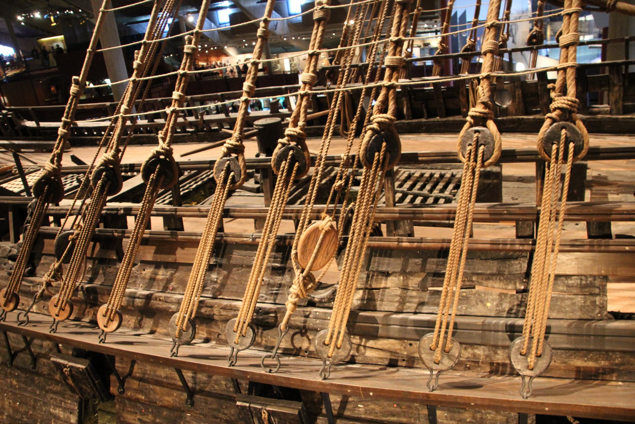
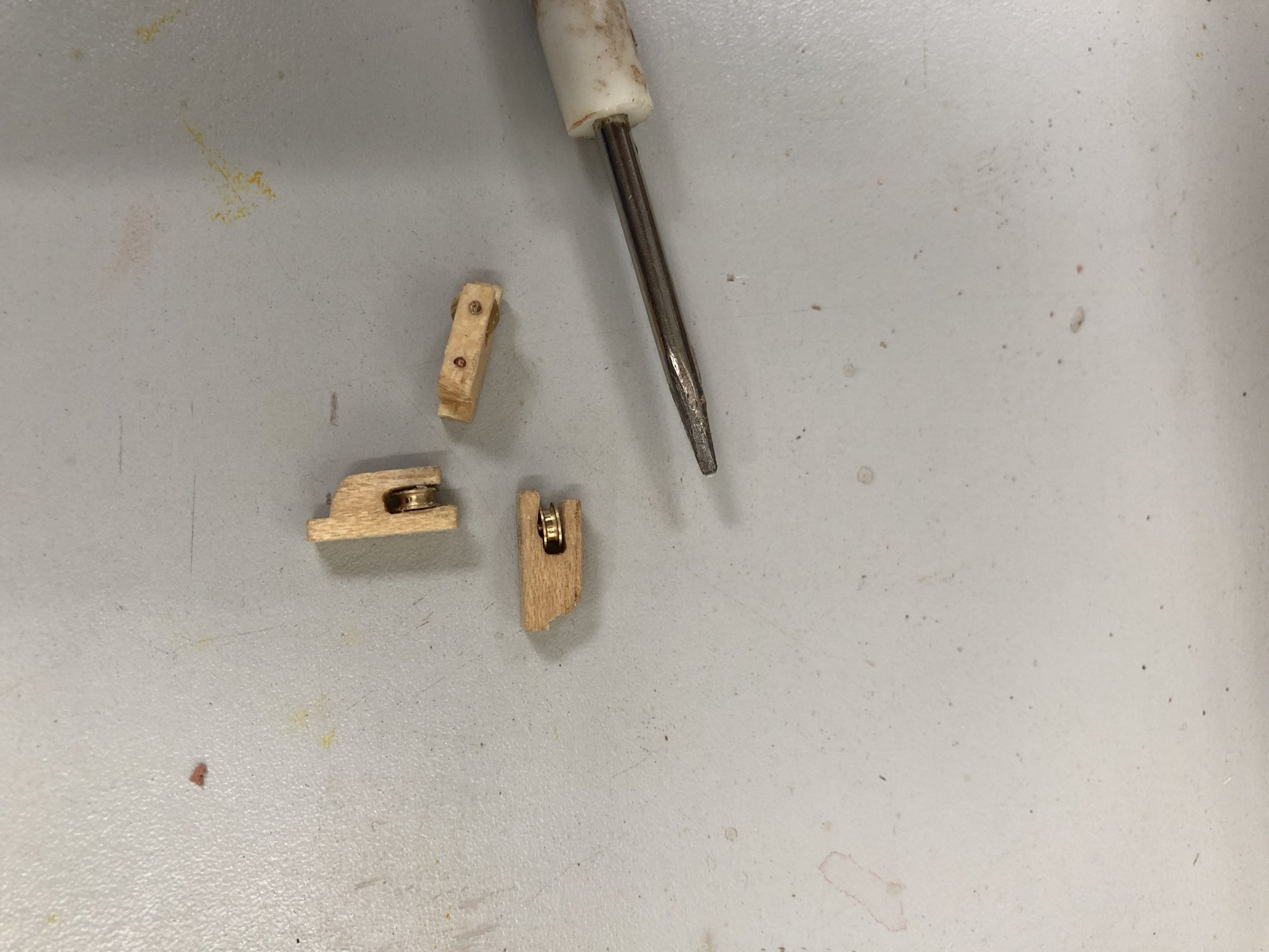
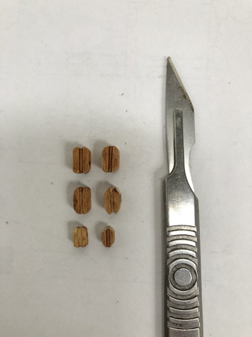
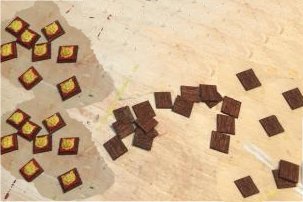
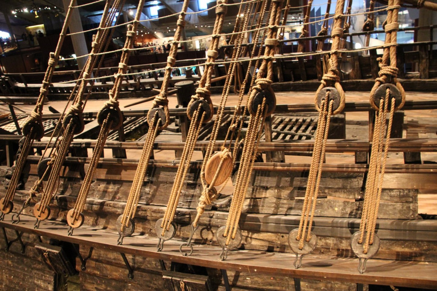
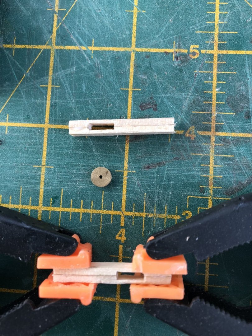
Many thanks Maarten. I look forward to your getting back to me. Happy travels... Within the Billing Boat kits, there are the required blocks for the rigging. In preparation for doing the rigging, I thought I would check these, especially as I have seen a number of builders purchase third-party blocks to improve the rigging appearance on their models. In the kit there are: - 180 Single block 5mm - 20 Double block 5mm - 14 Single block 7mm - 13 Double block 7mm Total of 227 blocks. In addition, there are some blocks which are like 'heart' blocks or multiple strand blocks which are laser cut plywood. The total 227 blocks are in a 'kit'-typical, quite hard, fine-grained timber which is light in colour (a straw, or off-yellow). I am unsure what the timber is, but it sands well and can be shaped without splintering or splitting. It does not however take a stain well, presumably due to its density. When I tried to stain a sample of blocks with a quite dark, mahogany brown stain, it changes from the straw colour, to a blotchy brown. Its as if the timber is not absorbing the stain into the grain. The problem I could most greatly see however is the block shape. Although pre-drilled and with grooves on the outside for tying a support or securing line, the 'corners' of the blocks were almost square, or rounded-square so each block is almost rectangular in shape. Real ship blocks are not square/rectangular. Below is a photo I took in 2017 in Vasamuseet, of some of the displayed block pulleys and deadeyes. As is typical, the blocks are rounded, some almost elliptical, and others egg-shaped, depending on where on the ship they were used. In any case, they definately did not have squared corners. They were also a relatively dark brown in colour (probably of oak timber). So, I had a choice - I could go and purchase a LOT of blocks made commercially (and there are a number of outlets that can provide these), but it was going to be expensive OR I could try and modify the blocks I had, to better simulate real blocks. I had nothing to lose in modifying them. If it didn't work, I could always go and spend more money and purchase commercial blocks. I started by mounting my Dremel in its stand and mounting a 1 cm grinding wheel. By holding a block in a non-release (opposite acting) set of tweezers, I could bring the block corners onto the Dremel wheel, smooth the corner by eye and then rotate to the next corner. Obviously, as I ground down the corners until rounded, I also ground away the 'grooves' that were in the original block for rope-tying. So, after rounding the corners, each block had to have the grooves re-created to allow the ropes to be located around the body of the block. This could only be done manually and it was slow and painful work with fingers not happy after the first few, on objects so small. After a long time however, I did manage to get a reasonable compromise. The photo below shows a range of the modified blocks with the original along the left row and the altered blocks along the right. The end result is not too bad for shape. I am not however happy with the colouring. The above is after staining of both before and after re-shaped blocks, and while it is OK, I think a darker brown may be better. You can also see the 'blotchy' appearance. I will experiment with some additional brown washes/paint to trial a better colour. Time elapsed: 1425 hours Best Regards, Peter G.

- 61 replies
-
- 2
-
-
- billing boats
- vasa
- (and 1 more)
-
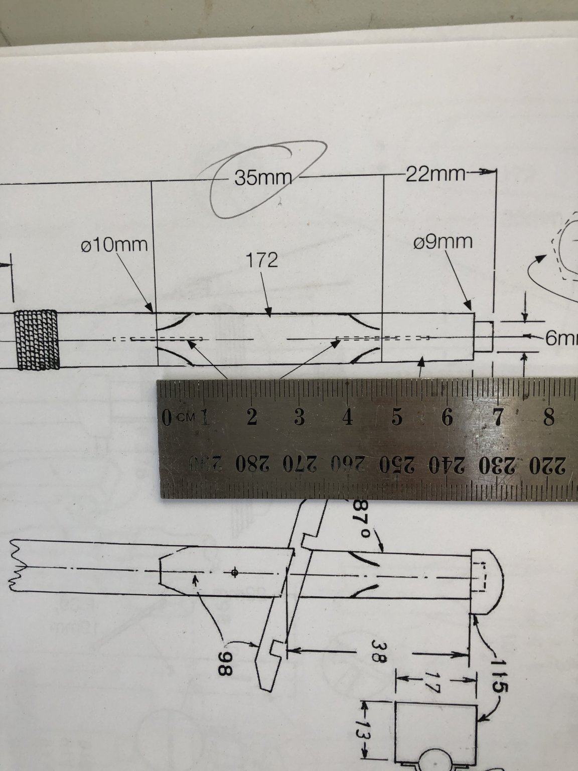
I am at the stage where I am preparing for masts and rigging. I am doing a bit of background research and reviewing the Billing rigging plans and those issued by Vasamuseet (many thanks to David Teel who provided me with these!!). I have also been examining the PDF build instructions for the De Agostini Vasa. While this is not my build kit, it does offer some ideas on the way forward in the rigging. For example, once the masts are available, the Build Instructions for PDF No. 12 provides information on setting out the rigging attachments of the foremast, main mast and mizzen where inboard braces are described first. This is ahead of outboard bracing to the chainplates etc, and this seems reasonable, as access to these lines will be hampered once the outboard lines are in place. I have also been reviewing the Billing instructions. While in general these are quite good, there is a lot which is not intuitive and where deductions have to be made. There are a number of straight out ERRORS too which is really frustrating. For example, a lot of the masts and spars in the Billing Plans are 1:1 scale. This is great as it allows you to check your lengths of dowling/masts before cutting BUT: 1. The lower lengths of mast sections DO NOT include the parts of the mast which lie below deck. This has to be added to the section lengths shown. 2. Because the above is the case, in some instances the material supplied is barely enough, and in one case, NOT ENOUGH material is supplied. 3. In the photograph below, is a picture of the Billing Plans, for the lower mainmast. Billing construct their masts with their 'square' portion as being a section of square timber material (Part No. 172, in this case), inserted between two round mast sections. A centrally drilled hole at either end with inserted brasswire is then used to secure the three pieces together. In the picture below, note that the squared section is to be 35 mm long. Note in the above, that the scale is 1:1, therefore the square piece should be 35 mm. The scale ruler shows the actual measurement is 47mm. The indicated cut length of 35mm is therefore WRONG. The kit does not provide much spare material for masts and fittings. If you get this cut wrong, you have no spare to account for the error!! As it happens, the Foremast squared material (which uses the SAME timber), has a 35mm length requirement, so I am assuming this is where the error has come from when marking up the Plans. In general I am very happy with the Billing Boat kit of the Vasa, but this type of mistake in their instructions makes it very difficult and frustrating. It also demands that you 'measure twice and cut once (and ponder the consequences if wrong)". Regards, Peter G.

- 61 replies
-
- 1
-
-
- billing boats
- vasa
- (and 1 more)
-
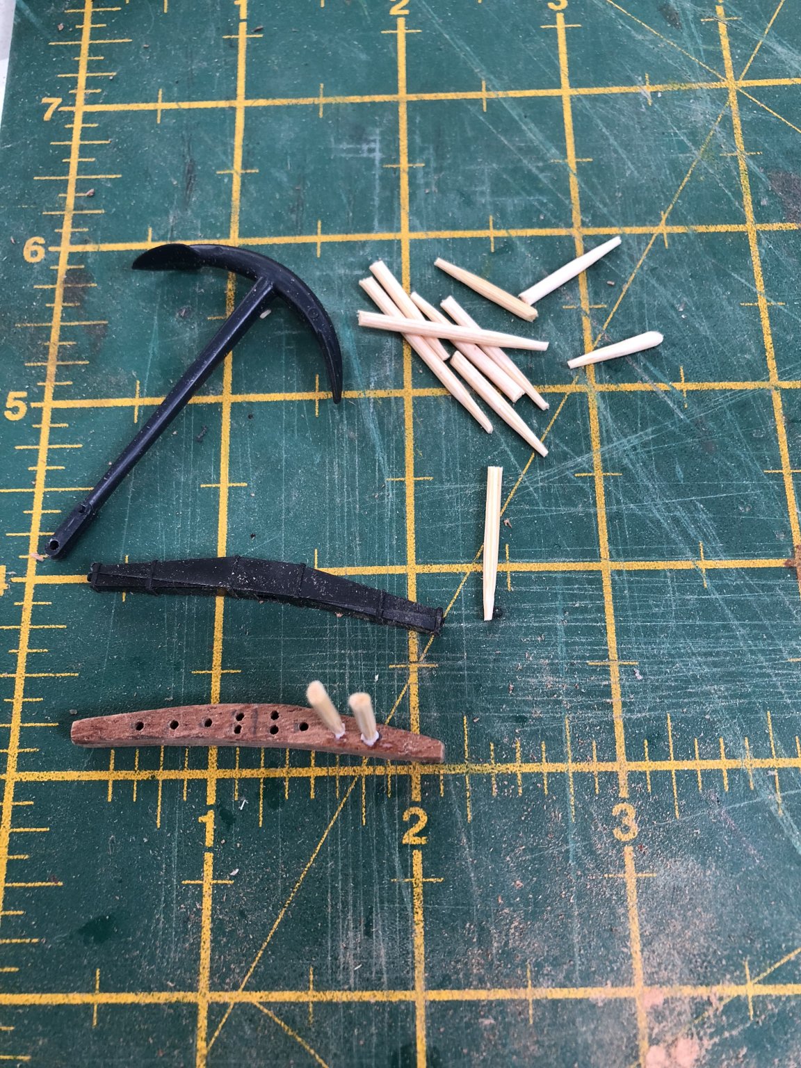
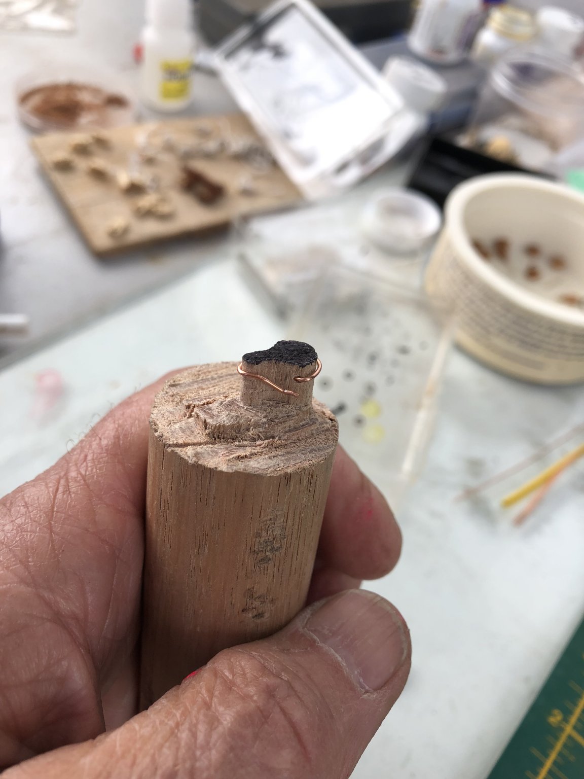
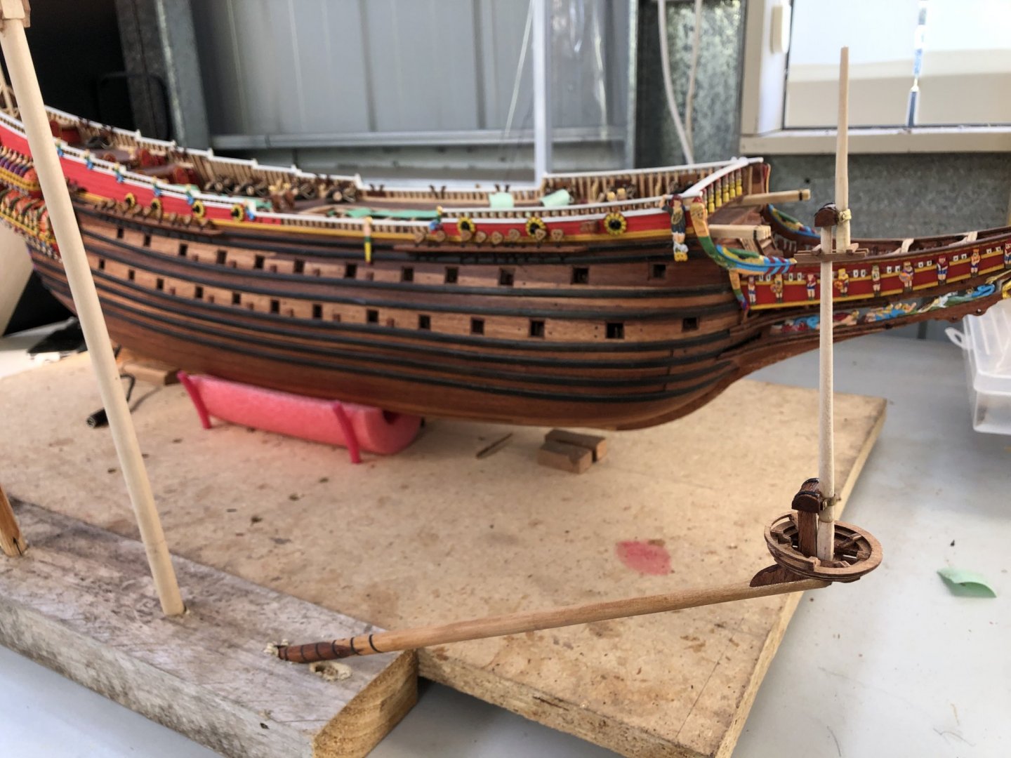
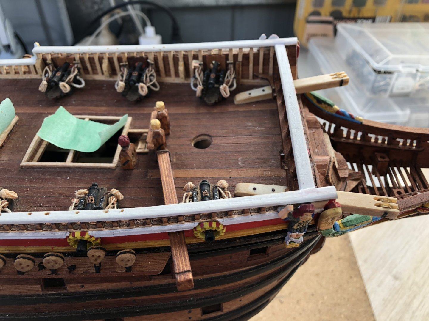
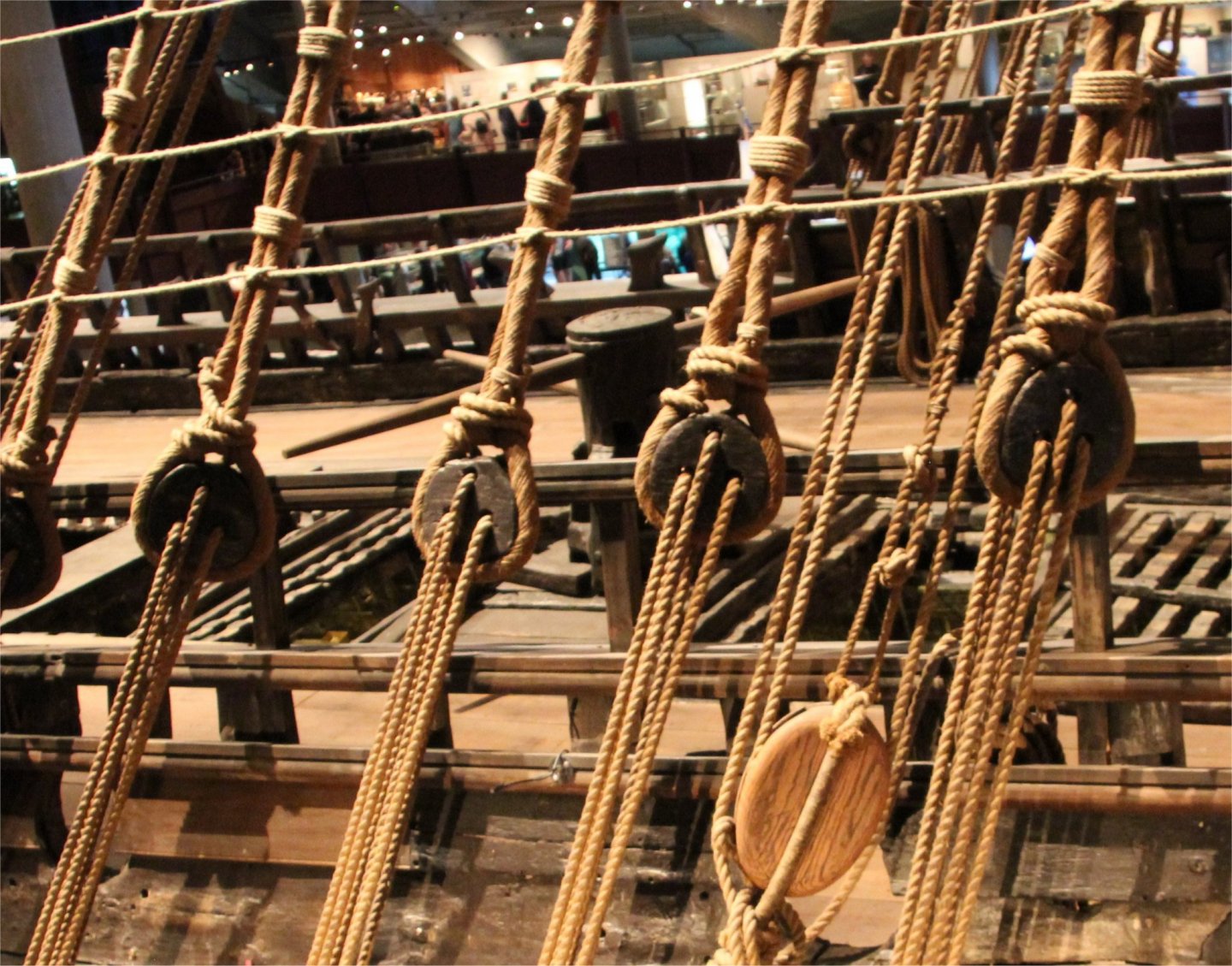
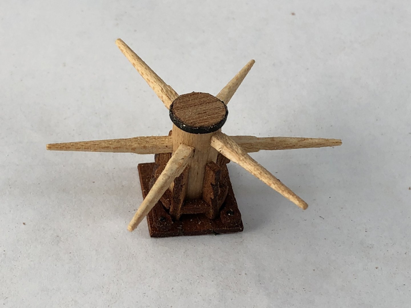
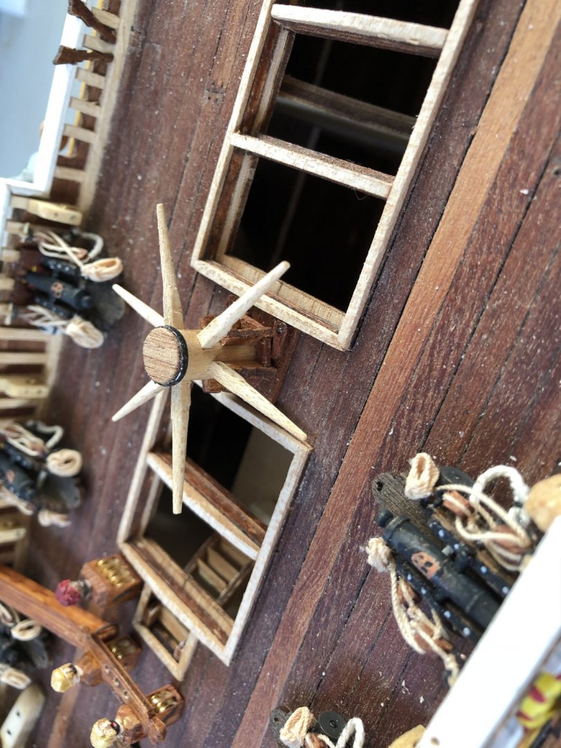
A couple of additional topside jobs before getting to the rigging (is there an end to these jobs???), I need to add the anchor poles to the bow, plus I need to make the capstan. The anchor pole(s) I noticed from other builds, is usually only an anchor pole (singular). The topsides have two square holes on each side of the bow railings for these poles, but usually only one pole was deployed. They are removable and can be put on either side of the ship depending on the side that anchoring was to be used. The pole extends from near the centreline of the ship and is secured by some rope which is passed through two holes in the deck and is then tied off at the inside end of the pole. The other end extends outboard and is grooved for rope to hold an anchor supporting pulley. My pole is shown in the photo below. The securing inboard rope can be seen just near the forward knightsheads. I used Obechi timber and stained it which shows a nice grain of the timber running along its length. The pole emerges through its square, railing porthole just aft of the most forward gun on the starboard side. The capstan I wanted to replicate was as close to the one on the original ship as best I could and so I looked at a number of the photographs which document it from Vasamuseet. Below is a picture of the actual capstan on the original ship, a little hidden by standing rigging, but it does show that there are four capstan handles, and these join the capstan trunk at two different heights. I know too that there are another two holes in the trunk for a third pair of handles which can be inserted (but are not on the sip as displayed). At the top of the capstan is an iron band and at the base, there are two 'ratchet' pawls which were used to prevent the capstan from reversing when the pressure of a line was hauled. These two pawls operate in opposite directions, depending on the direction the capstan is being turned. Additionally, the capstan handles themselves are quite long and would be about 1.5 times in length what the capstan is in height. The height is defined in the Billing kit instructions. The handles also taper to their ends significantly. On the capstan from the 1/10 model beside the original ship, (as shown below), the capstan has 3 pairs of handles inserted. Note that these are of differing heights as they feed into the trunk of the capstan, (as on the original), and the insertion ends of the handles are squared rather than rounded. With all the points taken into account from above, I made up the capstan, essentially from the kit parts, but with modified handles, and I opted for using six handles as shown on the 1/10 model. Its a little hard to see in the picture below, but I have added the two pawls at the base of the capstan. Positioning of the capstan is on the deckspace between the two forward hatches as shown below. The positioning, as per the original, has the pawls located towards the aft. I have used a round cap at the top of the capstan above the iron band with a thinned piece of Obechi which shows a nice grain. The iron band is a wrapped thin piece of blackened strip cut from an aluminium can. Two thin wire copper nails were used to secure it into the trunk of the capstan. Time elapsed: 1365 hours Regards, Peter G.

- 61 replies
-
- 4
-
-
- billing boats
- vasa
- (and 1 more)
-
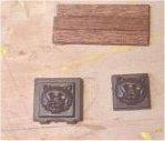
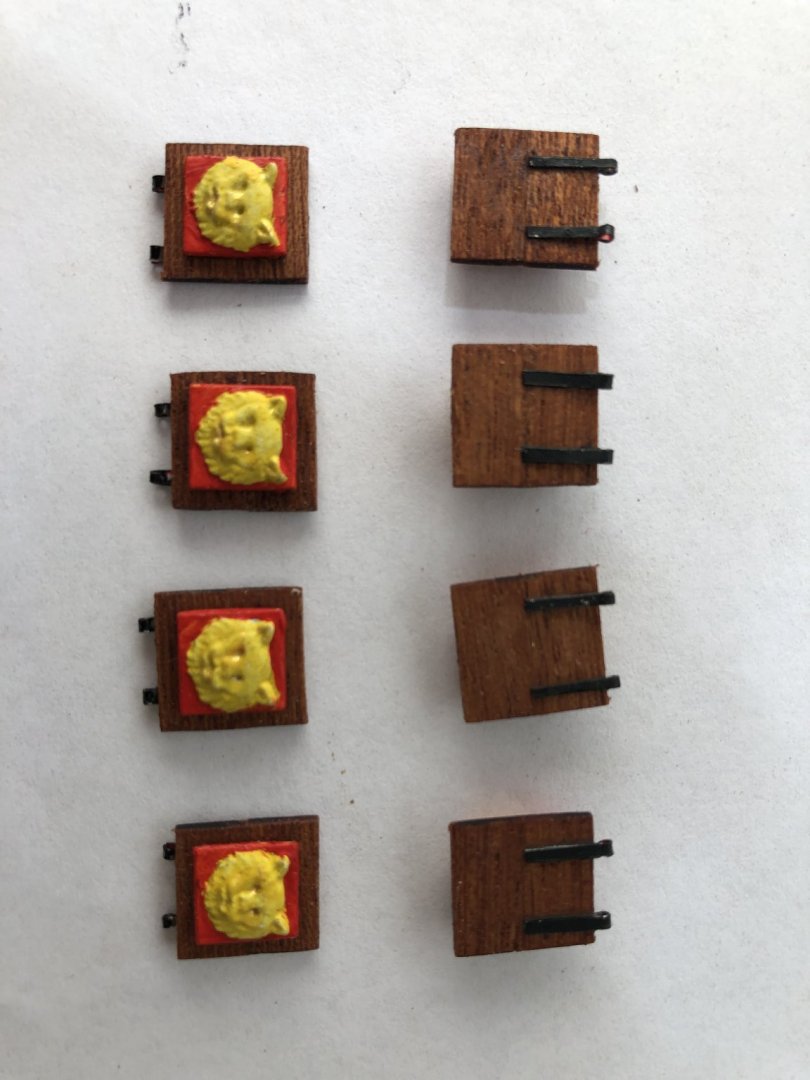
Where too next? There are 82 cannon port doors which have to be modified and constructed. Oh goody, some repeat operations. Billing Boat's supply two kit part sets for the cannon doors. These are a plastic surround set for each gun opening through the hull and a second plastic set of doors, complete with the ornamentation of a lion's head molded into the surface of the door. Right back in an early post where I was planking and cutting in the gun port openings, when planking was completed, I lined each gun port with four small pieces of Obechi strip to line the inside and make the port outline. This process then removed the need to use the plastic gundoor linings. For the gundoors themselves, I decided that the lion sculpture was a necessary part of the ornamentation, but the plastic, outer door material, I did not much care for. The picture below shows an example of a plastic door with the lion head molding. To create the gun door therefore, I initially took my fine modelling handsaw and cut the four sides of the raised portion around the lion's head to remove the excess (see photo). The thickness of the plastic was a too high to look authentic, so I then sanded each door to about one half its thickness (see photo below). Meanwhile, as I was fashioning the lion's heads, I glued some mahogany strips together and then cut them to the same size as the original plastic door. I then fixed the lion's head to the mahogany doors, using horizontal timberwork for each door. Finally, with each lionhead glued to the door-size timbers, I cut out lots of thin aluminium strips (the metal in Coke cans is about the right thickness and cut into strips about 2 mm across. An Exacto knife can cut the aluminium.) These aluminum strips I then bent around a small drill bit, and cut off the length of the double fold to a specific, scale length. These strips then formed my gun door hinges, which were CA glued in position with two for each door. The final result is as below: The hinges and lionsheads have to be correctly positioned of course, as the door, when open on the ship has the hinges at the base and the lionshead looking out from the ship. For each door, I will have to add screweyes to connect the opening and closing lines before the doors are attached to the ship. The door attachment is likely to be two copper angled wire 'nails' to act as hinges. I have successfully trialed this on a small piece of vertical 'hull' and it does seem to work quite well, but it will be difficult to get them all looking correct and even etc. Time Elapsed: 1355 hours Regards, Peter G.
- 61 replies
-
- 5
-
-
- billing boats
- vasa
- (and 1 more)
-
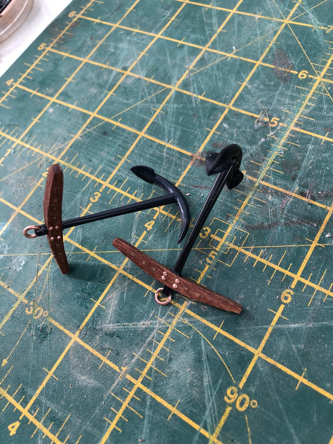
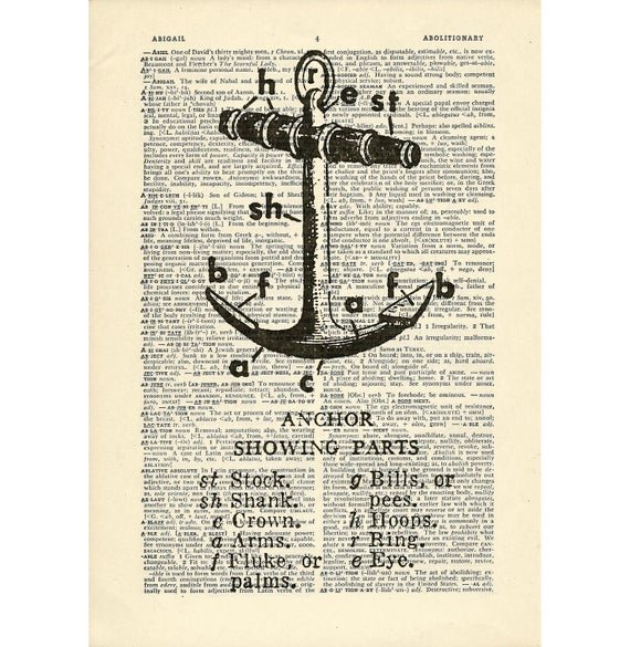
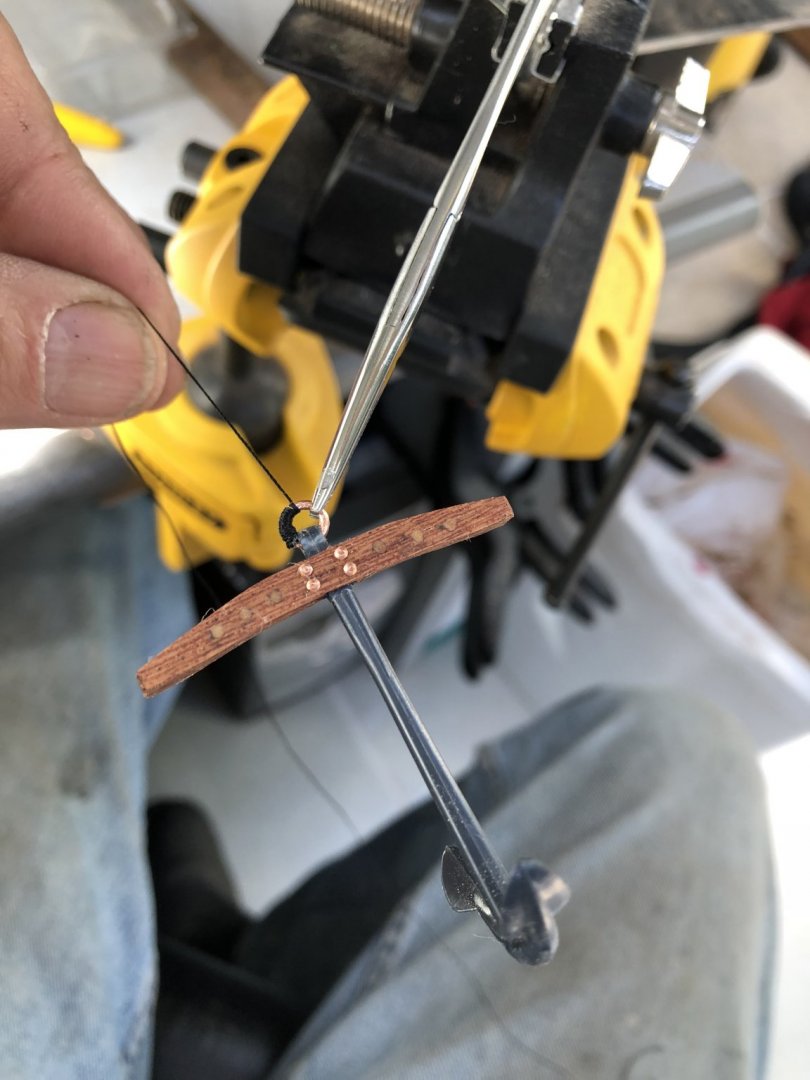
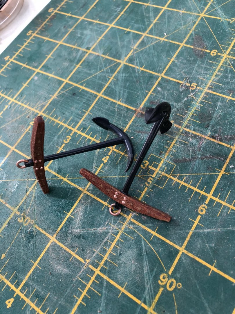
I added the 'cat' posts to support the pulleys for the weighing of the anchors on the port and starboard sides of the ship's bow. These are mounted directly to the deck and go through and under the front railing. They had to be cut into the shape of the lower rail of the railing but this is easily done by some filing and a sharp blade. The outer ends of the posts have two pulleys with a common axle and the ends of the axles are terminated by 'steel' cover plates (made using black paper and glue). The inner ends of the posts (which were shaped as per the Billing instructions) to grade down in slope to the aft, were secured by two large copper nails as shown in the photo below. Having positioned the anchor support posts, I decided to undertake the anchors today. To assist with getting the names of the anchor parts correct, I referred to an 'old' anchor diagram: The Billing Boat kit supplied anchors contain the main flukes, shaft, crown, ring etc in black plastic. The stock was also in black plastic but molded to simulate wood and with four simulated steel bands (hoops). While the flukes and shaft could be made to replicate steel (with a little black and brown wash, to indicate rust and age), the plastic stock I was not happy about. Firstly it had no 'grain' like timber and also it had the simulated 'steel bands' which the Vasa did not have and to remove them would affect the plastic surface. So, I thought I would create my own timber stock. The Vasa's anchors also had wooden tree-nailing rather than steel or rope bounded timbers comprising the stock. I wanted to simulate this effect. To form the body of the stock therefore, I used three 'planks' of mahogany and glued these together with clamps using white glue. I then shaped two stocks to match that of the plastic stocks and drilled a series of holes through the timber to take the pointed ends of cut-down tooth-picks. I found that the bamboo toothpicks for this job were not suitable as, when cut off at the timber's level after inserting and gluing, the internal porous holes of the bamboo could be seen. A better solution was to use pine toothpicks (I am assuming it's pine but maybe another, more dense and light coloured timber carefully selected from the QuarterMaster's store???) which did not show the end 'holes' of the timber nails. The picture below shows the supplied anchor shaft/flukes and stock, with my replacement stock and timber nailing. The number of timber nails used in my case was only three per side, (that's six per stock side, or 12 in total). The remaining four holes (per side) adjacent the shaft hole were to have copper, blackened nails inserted after the tree nailing. The inserted toothpick 'nails' were cut-off flush with the timber and then sandpapered smooth. A squared hole was cut/drilled into the underside of the stock just large enough for the anchor shaft to pass through and be secured. Once attached, a copper ring was made from larger diameter copper wire and offset to allow it to pass through the shaft upper ring-hole. It was then closed with pliers to stop it from coming loose. The join of the ring was rotated until it was enclosed by the body of the shaft. Below are the two anchors before their rings are bound with black rope. The final job to complete the anchors was to bind the rings with black rope and fix with some CA glue. Winding the rings was tedious and took a while because the rope has to entirely cover the copper ring, from one edge of the shaft to the other. If you run short of line, you have to start over again, so a longer length is recommended initially. It's surprising how much line a tight winding around the wire ring took!! Below is the winding process while the anchor is held in a vice with some suturing scissors. The final product had some burnishing oil on the timber and the nail heads blackened. The tree-nails can be seen in the mahogany and are subtle in their appearance which is what I was looking for. Overall, I am happy with this end product. I will leave the mounting of the anchors for a little while until I sort out the pulleys to be used and the rope detailing. Time Elapsed: 1250 Hours Regards, Peter G.


- 61 replies
-
- 5
-
-
- billing boats
- vasa
- (and 1 more)
-
Michael, My apologies for not having responded on your comments about Vasa’s cannons. Many builders have discussed the various aspects of the Vasa’s cannons at length (including yourself, Nazgul, Mark3l and others). My treatment of the cannons is not as good as I would have liked, and I may revisit them, but at this stage, they don’t look too bad, and I will move on to other areas of the build first. Regards, Petet G.
- 61 replies
-
- 3
-
-
- billing boats
- vasa
- (and 1 more)
-
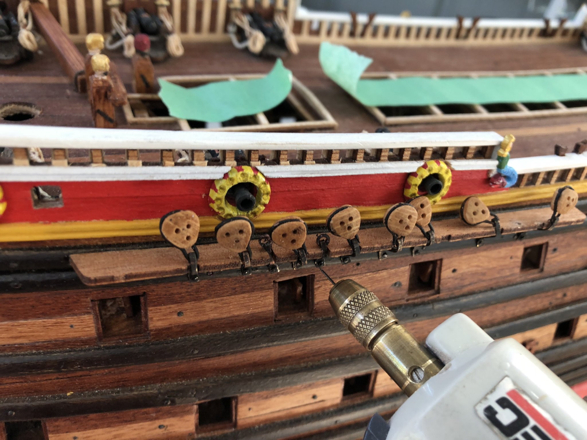
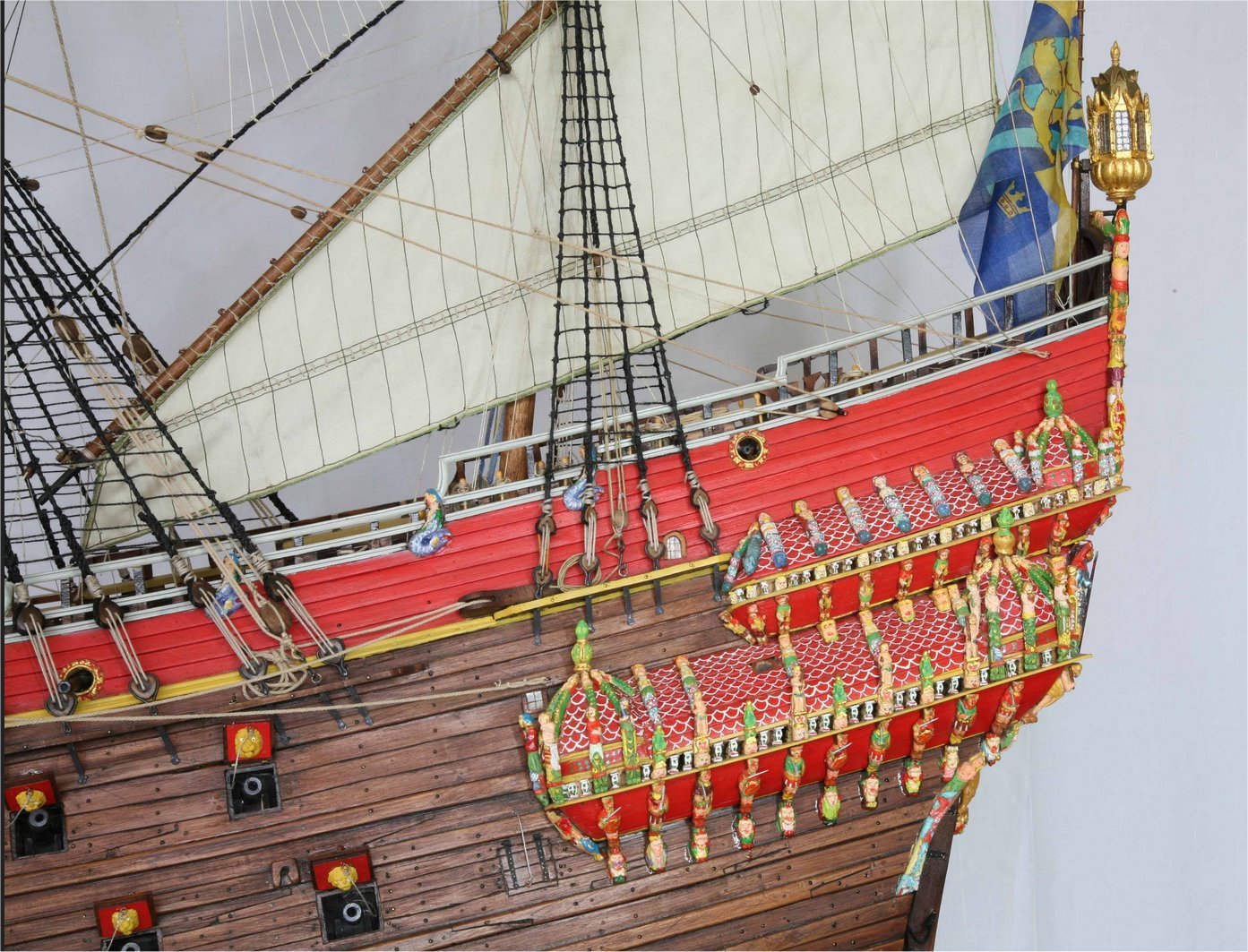
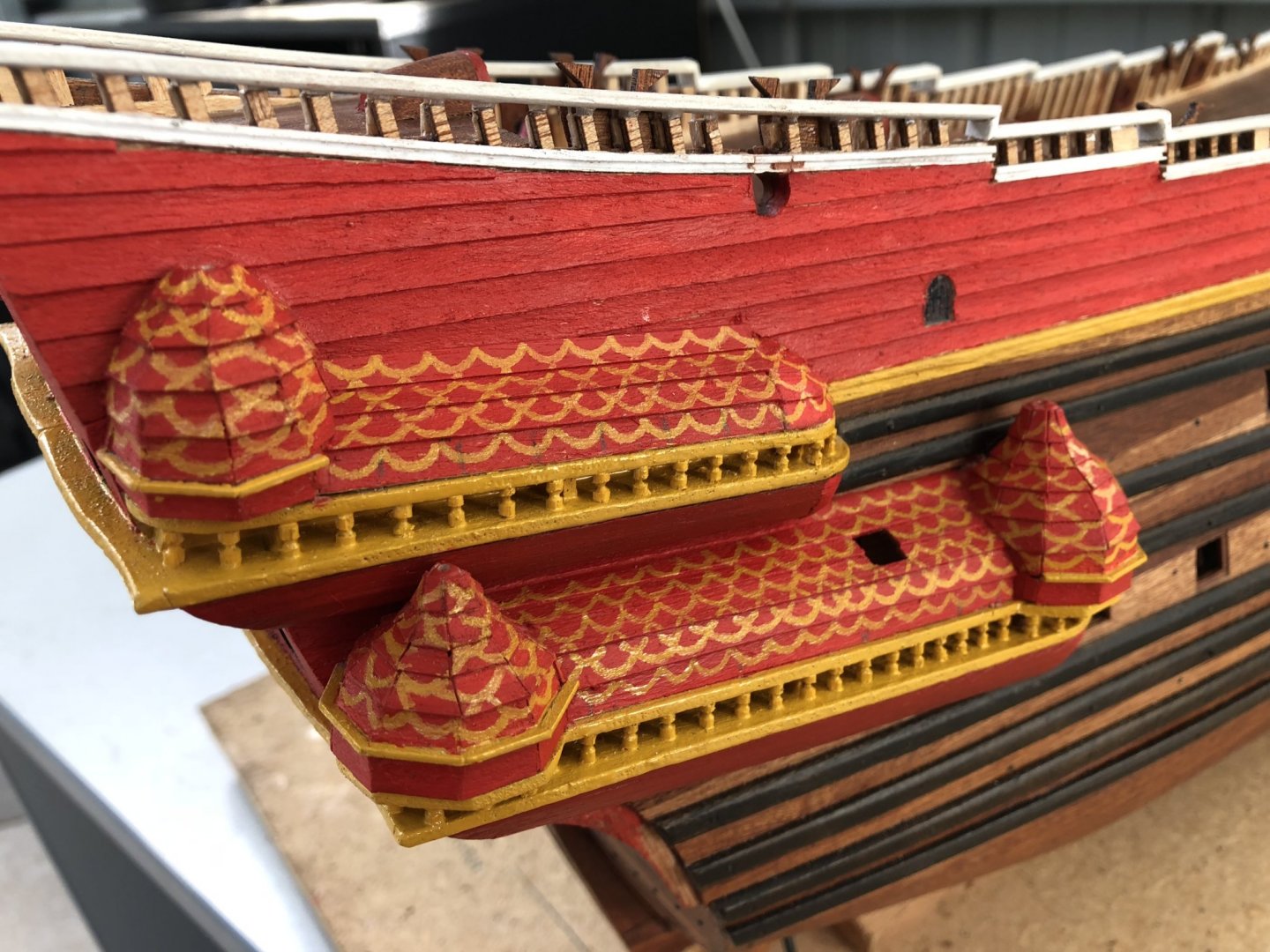
I thought it might be time to attempt the chainplates along the flanks of the ship. It is interesting when reviewing pictures of the real Vasa, that two things stand out: 1. The positioning of the mix of chainplate positions for the deadeyes AND brace pulleys is located such as to allow a minimal, but clear view from the various gunports and cannons to fire clearly through the lines. The clearances are not large, but enough to allow a clear shot to pass through where no offset or angle of shooting is used (which would have been the norm). Additionally, in some instances, particularly where the chainplate is serving a mast with significant rake angle, the deadeye or brace line may be positioned directly in front of a gun, but the angle of the line up to the mast is such that it provides gun shot clearance. 2. The deadeyes themselves in most instances, especially for the larger, low chainplates, are NOT round. They are shaped like an eccentric 'egg' with the upper curvature significantly broader and of larger radius than the lower, curved bottom of the deadeye. These two points are indicated in the photograph of the museum Vasa below. This picture is of the mainmast chainplate: Even the aft, mizzenmast chainplates with their smaller deadeyes are not round, but shaped like an 'egg', see below. Note too that the braceline attached to this chainplate has its own strop attached to the top wale beneath. Strops too, made of iron on the real ship, may be angled considerably to account for their individual alignment of their deadeye and the mast rake angle. So, to simulate the above shapes, I have decided to sand every one of my deadeyes to this egg-like shape (wow, what was I thinking)!!! There are a LOT of them. However, job complete. Following the sanding was some mild wash staining with examples of a few completed below: I experimented with the steel securing straps that surround the deadeyes and the most successful, assembly line approach I could devise, was to create a rounded piece of broomstick, which I cut down on one end, shaped and drilled a hole into for some medium weight copper wire. I then inserted one end of the wire into the hole and wound the wire once around the shape I had carved. Using my thumb to push the wire into the indented shape, I then cut the wire, removed it from the broomstick jig, and soldered the ends. These then formed the perfect shape and size for all my large deadeyes. The smaller deadeyes just required the same process (at the other end of my 6" broomstick), and I then had all the metal strap surrounds for the deadeyes with the extension shape beneath to attach to the brass strop. I used Brass Blackit to colour the copper wire and job done. The wire surrounds tightly fitted over the deadeyes and then with pliers I simply squeezed them a little, and the wires were secure and the correct shape. I broke a few solder joints with the pressure applied but these were easily repaired. Adding the deadeyes to the brass strips supplied by the Billing kit, was a simple bend and cut after measuring, and then a scale railroad tie was used to secure the deadeye strop to the top wale of the hull. Each nail was pre-drilled to ensure it would go in accurately and straight. The brass strip coming up from the wale was bent around the chainplate, cut to length and angled within its groove cut in the chainplate timber. Positioning with the correct angle was important. To do this, I temporarily inserted the masts and ran a stringline from the top, lower section to the deadeyes to get the alignment and ensure correct clearance for any gunports. Note too - In the picture above, I have placed green masking tape over the hatches - I am sick of dropping 'stuff' into inaccessible places and this stops that. when the hatch covers are placed on, the problem goes away, but they do catch a lot of dust!! Once all deadeyes and brace lines were attached, a thin cover strip was glued over the strops to hold them in place and retain their angles. I tried really hard to give reasonable gunport clearance. For a couple of cases, I would not like to have been the gun aimer, especially in firing anything other than straight ahead!! I did have to change the number of deadeyes and brace lines from those recommended from the Billing kit Rigging Plan. I preferred the Museum Rigging Plan and will be adhering more strictly to this, than that of the kit. Time Elapsed: 1235 hours Regards, Peter G.


- 61 replies
-
- 6
-
-
- billing boats
- vasa
- (and 1 more)
-
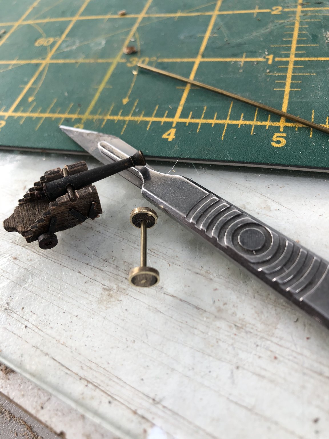
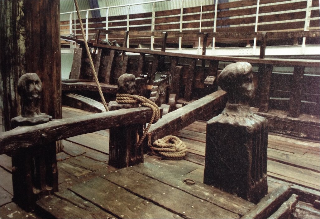
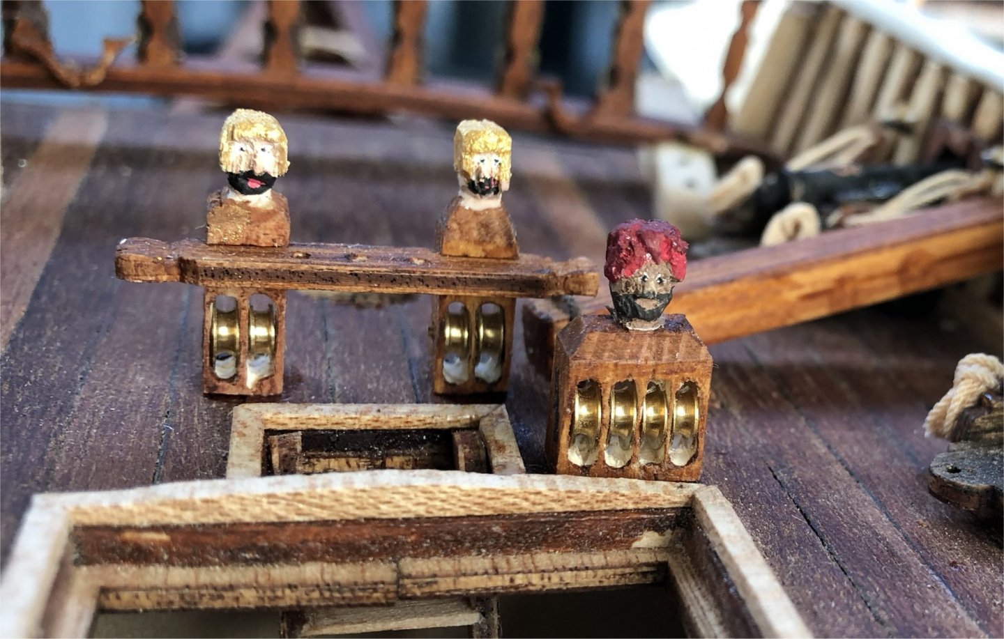
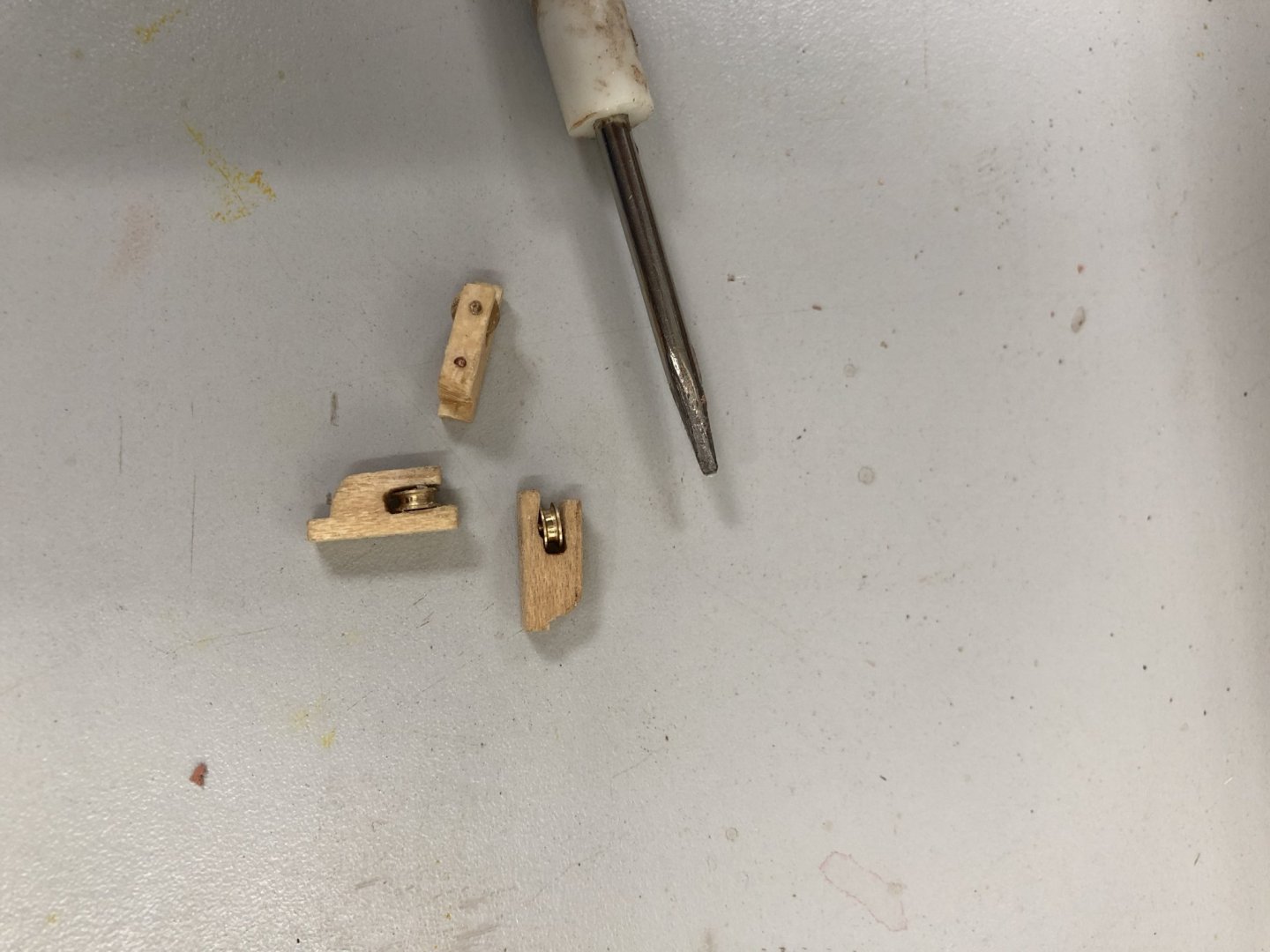
On deck, some of the furniture has to be done... Firstly, the knightheads. In total there are seven knightheads, used on the Vasa for belaying and running ropes where tension, even back to the capstan may be required. Each knighthead has one, two or four pulleys mounted within its square or block lower portion and then above this is a carved head. These heads on Vasa were of the heads of Roman soldiers, some attractive damsels, or a dark, swarthy gentlemen with a turban. Photos of some of these are shown below: Notice in the photo directly above, that there are four pulleys mounted in the righthand block near deck. I have attempted to carve these figures and only when I had a head I was happy with, did I bore the holes below for the pulleys. The carving was more prone to disaster, so this was done first, and there were a few disasters along the way!! Eventually I managed to get six of the seven constructed, but the seventh was the four pulley block and this needed a different approach. I was unable to successfully drill, bore and file four separate pulley openings without cutting the very thin layer of wood between the pulley wood walls. I do not have a milling machine, but even if I did, at this scale, I think the wood would still tear when less than 1.0 mm thick. My solution was to carve three pulley openings and then add a fourth by laminating a piece of timber to one side which had already been indented for the pulley opening. This proved successful and the result is shown below with my turbaned-headed gentleman. I have stained the outer sides of the knightheads but have missed the pulley openings, so I will have to go back and stain these too - whoops - I only just noticed it from the photo. The next items I tackled where the 14 sheet handling pulleys which are mounted on thwarts between gun carriages of the weather deck. Although not obvious, these can be seen along the port side of the Vasa in the photo above. These were made of laminated Obechi wood pieces, glued together and then cut at appropriate locations before inserting pulleys and axles. Below shows a picture of the laminating of the pieces and below that, the final sheet pulley assemblies. The pulley wheels were of brass and supplied with the Billing Boat kit. A copper nail above the pulley axle end was also added as a means of securing to the thwart timbers. The pulleys were mounted along each side of the ship, approximately between each cannon carriage where the sheets could run freely from the yards and upper rigging. Time elapsed: 1175 hours Regards, Peter G.
- 61 replies
-
- 5
-
-
- billing boats
- vasa
- (and 1 more)
-
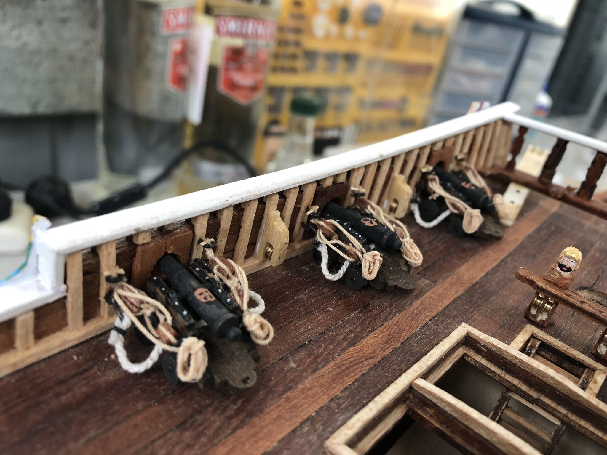
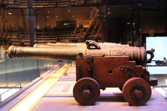
And so we move to the deck and topside fittings. In particular, the cannons. A lot has been provided in other build logs about the cannons for the Vasa. Their design was of bronze with ornamentation and relatively conventional trucks as below: The cannons provided by Billing Boats are of four types: a) The truncated barrels only for the below deck installations. These have been accounted for by 'artificial' gun carriages installed during planking of the hull. I have not placed them in the ship yet, but their positions have been drilled and are ready for fitting. The gun doors will be described in the next post. b) The main weatherdeck cannons which are mounted on slightly larger carriages. These are mounted along the foredeck areas and are there are six of them. Interestingly these guns have not been supplied with barrels that are any different from the slightly smaller carriage mounts to be placed amidships. c) The midship cannons use slightly smaller carriages but the same rope rigging and load arrangements. d) Two smaller upper, stern weatherdeck carronades which are provided with gun carriages that appear to be similar in design to field artillery. These I did not like with their large wheels and unwieldly shaped cannon carriage frames. So, I scratched two mounts for these smaller barrels that I am much happier with. My difficulty in modelling the cannons related to the ornamentation of the barrels. The barrels supplied are brass, but with plain turnings and no ornaments. So, I had the choice of buying a set of say, Amati cannons with ornamentation (as similar to English 18th century ships), or attempting to modify the ones provided. A third option was to cast new cannons, probably in resin. I looked into this and may still attempt it, but they are small, and I haven't done it before. My solution at this stage, was to solder each barrel with some solder at the rear that I then scribed with some 'make-do' ornamentation. Small and time consuming work to try and add the crest seen on the cannon above. The two handles, I attempted by soldering wire etc but it proved too difficult and made a mess of the barrel (so I scrapped that idea!!). Once I had the carriages made and together, I mounted the barrels, decorated them and added the various metal straps (at the wheels, four, and over the barrel axles) as below: I had stained the carriages a dark brown/black which still showed the grain of the timber without giving a 'paint-like' finish. The most time-consuming part of mounting the cannons, was the rope rigging. The recoil ropes were OK as they only required hooks at each end (which I fashioned out of bent copper wire) and screweyes into the main deck thwarts. The tricky part were the pulleyed rigging used for reloading a rolled gun inboard. Initially, I was not happy with the size of the pulleys supplied for this, they seemed too large. I scratched some smaller pulleys, about 3 mm, which I was happier with. As there were only 14 weatherdeck guns, times 2 x 2 for each side of the carriage, that was 56 pulleys required. Then came the rope to be used. I was not happy with the thinnest of the Billing Boat kit supply. It was too string-like, white and hairy (even if bees-waxed) - not realistic for this application. To overcome this, I then started researching the use of a ropewalk. This is a topic for another post, but needless to stay, I have had some success with a home-grown ropewalk that I can make assorted ropes of varying thicknesses and colours etc. This, eventually is what I used for the rigging ropes of my cannons. Below I show some pictures of the mounted cannons with their rigging. For each cannon I have added rope coils that are hanging from the rear of the each side of the carriages. I may have to tone-down the crests of each cannon. The contrast with the black seems a bit strong. Note too that the secured thwart ends of the reloading ropes on the upper screweyes are attached by a thin, shaped piece of toothpick. These timber locks were used on the 'real' ship for quick release of the cannon if required. To get them to scale was not a problem, but threading them through a secured loop of the reloading rope loops was time consuming. More soon. Time elapsed: 1160 hours Best Regards, Peter G.


- 61 replies
-
- 7
-
-
- billing boats
- vasa
- (and 1 more)
-
Many thanks for your encouragement EJ_L, Jonathon and Martyn!! Martyn, The mouldings of the De'Agostini Vasa for the clinker gallery planking, I'm sure would paint well and with the raised scalloping would give a great finish. There are going to be some beautiful Vasa models about with the completion of their models by De'Agostini. Have all the mailings, been completed yet? I know that these mailouts were progressive and not all released in some countries until later, so has anyone received the entire kit at this time? If not, when would the kit part mailouts be completed? Regards, Peter G.
- 61 replies
-
- 2
-
-
- billing boats
- vasa
- (and 1 more)
-
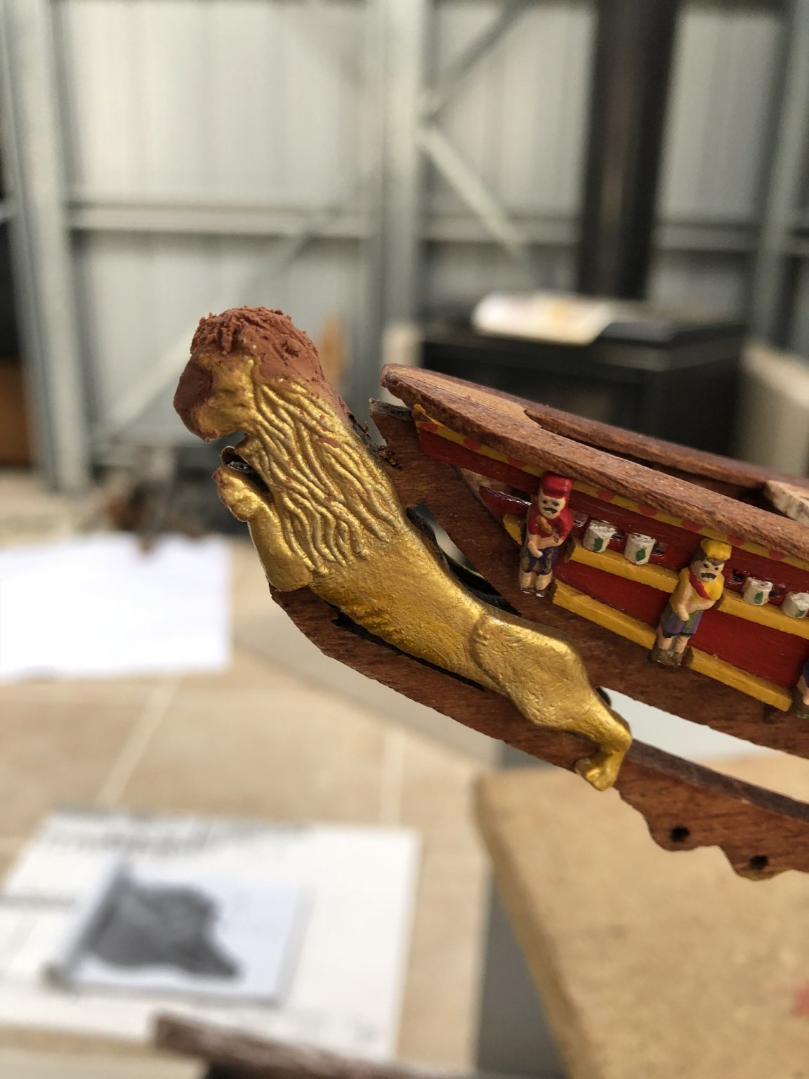
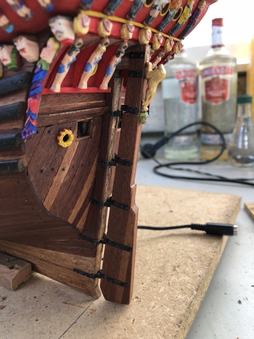
With the bow advanced, I then went on to adding the gold lion at the prow of the ship. In the Billing kit, this is provided with two plastic, scaled lion halves (which fitted around and sat on the timbers at the prow as an extension of the beak. The detail of this was not too bad, but the shape of the head left a lot to be desired. Similarly, there is a long lion's tail which extends from the starboard side body of the lion to lie adjacent the timbers on that side, but on the portside, there is no such tail extension, which looks really odd. So, to overcome the tail issue, I carved a tail extension from some frame plastic and shaped it like the mirror opposite of the other side. For the lion head, I looked at a number of internet pictures of lions, their manes and shape of the body relative to the head, and thought the best remedy, was to add some filler which could then be shaped to appear like the top of a true lion's head and carve the mane hair matting into that. The result before painting is shown below: Note in this photo, I have not yet added the tail extension. The next photograph, taken outside with a bit more light, shows the tail added. I have also finished painting and added the sculpture between the beak timbers just below the crew walkways and timbers. This you can see below. I believe that this sculpture was of Perseus from Greek Mythology, the slayer of the Gorgon Medusa and the rescuer of Andromeda from a sea monster. Perseus was the son of Zeus and Danaë, the daughter of Acrisius. Although most famous for the killing of the Medusa, Perseus was also key in the rescue of the Ethiopian princess Andromeda when he was on his way home with Medusa’s head. Andromeda’s mother, Cassiopeia, had claimed to be more beautiful than the sea nymphs. Poseidon had punished Ethiopia by flooding it and plaguing it with a sea monster. An oracle informed Andromeda’s father, King Cepheus, that the ills would cease if he exposed Andromeda to the monster, which he did. Perseus, passing by, saw the princess and fell in love with her. He turned the sea monster to stone by showing it Medusa’s head and afterward married Andromeda. The sculpture shows Perseus fleeing the sea monster with Andromeda at his heels. Another item added which took a bit of construction was the rudder. Where the timbers of the hull lie back in the line of the shape of the ship, for the Vasa, the timbers of the rudder were vertical. Also, at the top of the rudder is a headstock which extends into the ship and of course, was extended to the manual steering station under the weatherdeck. I added the gudgeons and pins for the rudder mounting which were a bit fiddly and used copper nails (painted black) to hold the gudgeon plates and gear in place. There was not a lot of room to manipulate the rudder into place and then position the pins. I should probably have done this before the stern sculptures were attached. Also at the top of the rudder, an upwards-facing lion and gargoyle are added. The lion again was provided by Billing's and as two separate halves which were CA glued together and then painted. The gargoyle beneath it however I could not find in the kit, so scratched this and painted it as per other build logs. Time elapsed: 1075 hours Regards, Peter G.

- 61 replies
-
- 3
-
-
- billing boats
- vasa
- (and 1 more)
-
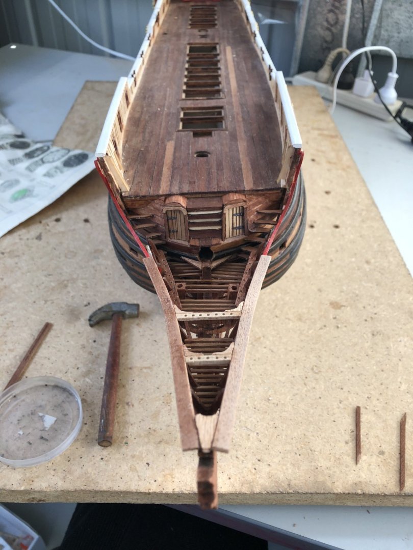
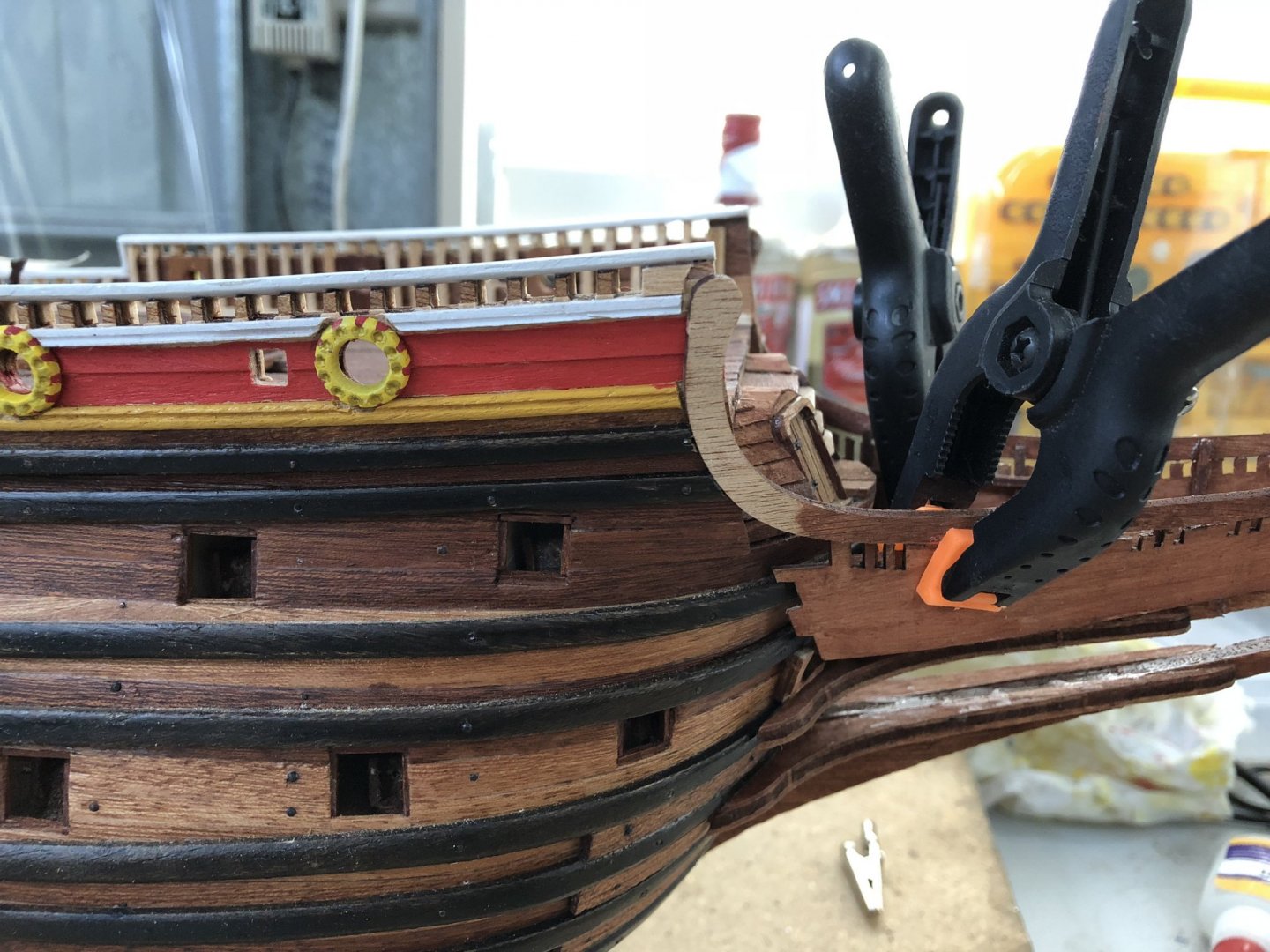
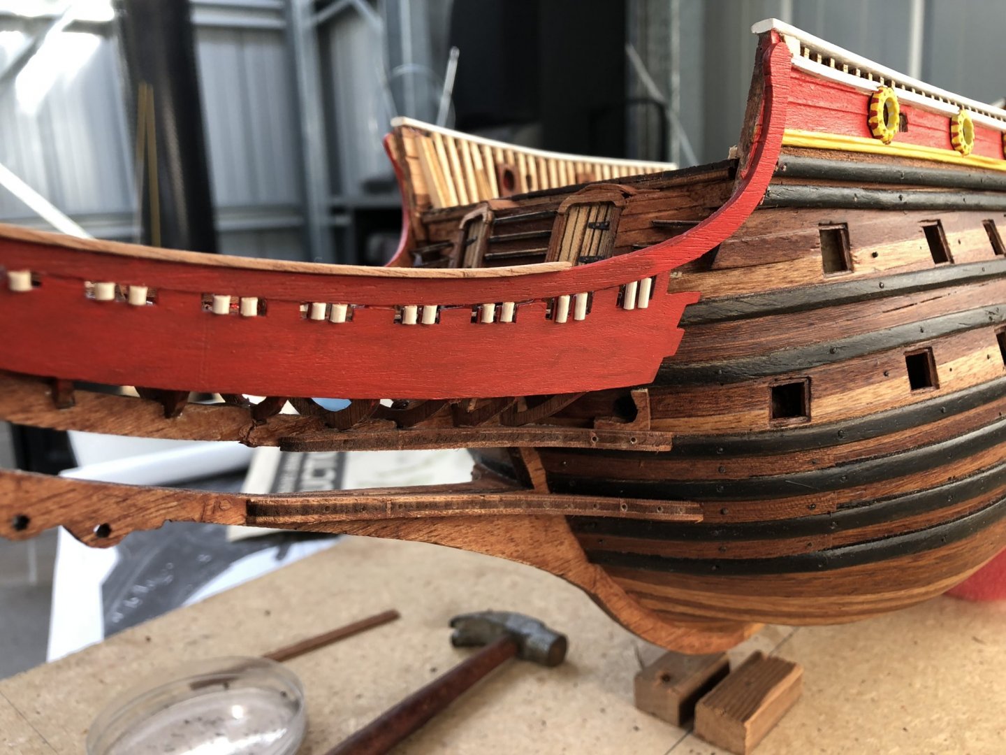
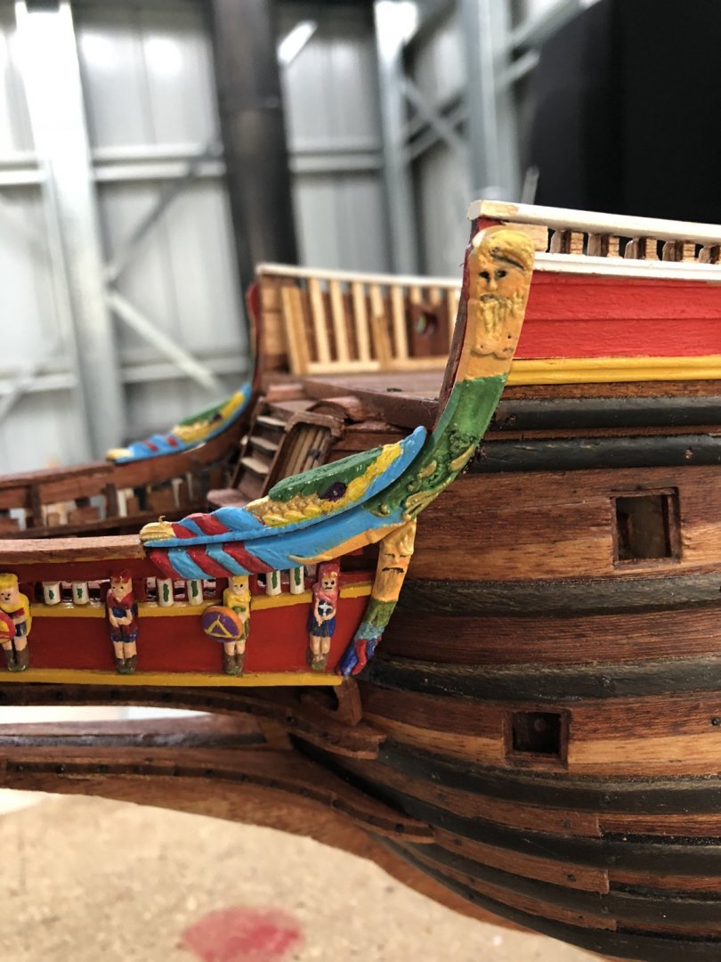
Moving from the stern to the bow, the beak was reasonably provided for in the Billing Boats kit and needed little addition of timbers to improve what is required. Alignment of the beak is critical and I got this a little wrong, but not a major problem. I only noticed this when I applied the upper plywood sheets that were a little tight on the starboard, but left a small gap on the portside. A bit of judicious pressure brought the beak back into line. In the above picture you will note that I have left out the enclosing timbers where the lashings of the bowsprit are passed down to the lower beak/bow timbers. This will enable the lashings to be better positioned and managed when the bowsprit is placed into the ship. I can then add the required timbers after these ropes are placed for a tighter, unimpeded arrangement. Also note that I have added openings to the beak crew toilets that are rounded. I have seen both square/rectangular open toilets and some with rounded tops. I can't imagine the difficulty of using these for the forward crewmen, but to just have a raw, timber edge would not have been comfortable, let alone dealing with the ship's movement and position beneath the pin rails located above them. I added the semi-circular timbers from the topside rails to the beak side panels and this took a bit of shaping to make them fit correctly. The aft and forward portions of these timbers are covered by sculptures but it still needed to fit correctly. The hawse holes for the anchor lines have been added (beneath the beak panels and adjacent the fourth wales) as well as some half rounded, small columns on the beak panels (made from splitting rounded toothpicks) which will be painted and infill the spaces between the artwork figures (Caesars) that are to be added along these panels. Having painted and decorated these figures, I added these with some surrounding strips of yellow timbers to the tops and bottoms of the beak sides. Fitting of the upper, shaped sculptures which lie on the beak railing needed some shaping and the painting required some alignment of colours to have the reds and blues carry through. The side sculptures have had the addition of some shields and swords where I thought appropriate. Between the timbers of the beak, beneath the bow walkways are a series of plastic sculptures which I have to paint and add. On trialing the placement of these, the fit is almost ideal so there will be no issue on attaching these once painted. Time elapsed: 1042 hours Regards, Peter G.
- 61 replies
-
- 5
-
-
- billing boats
- vasa
- (and 1 more)
-
David, She is looking really impressive. Your second planking gives the ship a lovely finish - When I built the Cutty Sark many years ago (using a Billing Boats kit, with single planking), I remember that after doing all that planking and finishing, to cover the lower portion with coppering seemed somewhat sacriligious, but then that is how the ship was/is and how Longridge did it in his book. Of course above this too, to the topsides the hull was black and again, this hides a lot of the very beautiful timber appearance of the model. Is there an alternative? - Only if you don't want it to be truly authentic. A really good build - Good luck. You progress is excellent. Regards, Peter G.
- 133 replies
-
- 1
-
-
- cutty sark
- mantua
- (and 3 more)
-
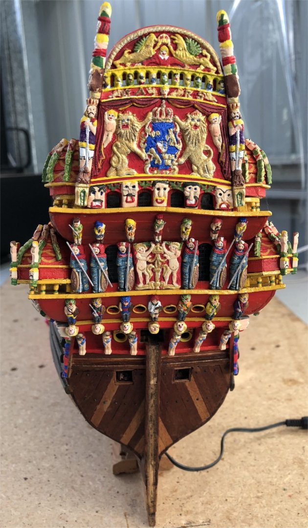
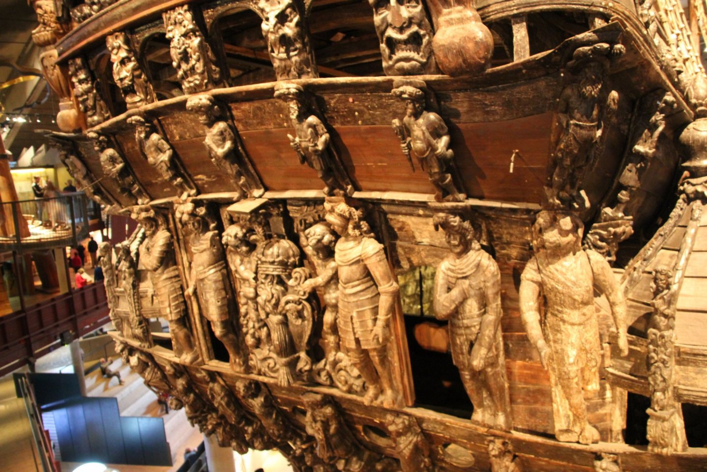
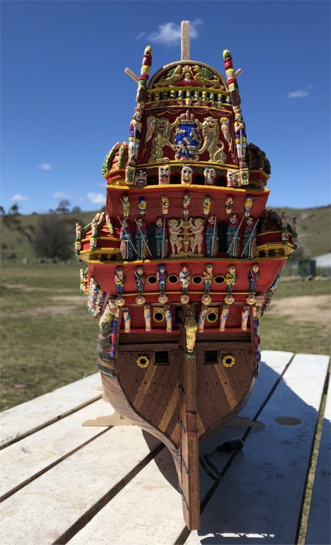
With considerable time and much painting, I have completed both the starboard and port side galleries and their artwork. The painting has taken the majority of the time but the shaping had to be carefully done so as not to melt or destroy the plastic figures. In the end, only a couple of retrievable disasters. The port quarter of the ship and the gallery artwork is shown in the picture below: Some of the finer detail on some of the figures will need adjustment a little later as I am not happy with some of the beards on the faces in particular, and the eyes in some figures too, are a little large. Its really hard to make the irises in the eyes small enough but also to line up with the left and right eye positions. Some of the figures look decidely drunk or cross-eyed. I will have a go at repairing this when my hands feel steadier!! So I now move to the artwork on the stern. The figures here are a mixture of large ornamentation pieces with quite complex detail (but on one piece of plastic base), as well as individual figures having guards/soldiers, musicians and gargoyle-like heads etc. In addition, on both the starboard and port rear corners of the stern are tall structures that extend above the topsides and require gradual and diligent painting as there are a number of kings and carvings like a totem pole. An off-centre photo of the stern is shown below: For the soldiers guarding the rear Captain's Cabin windows, I have added long 'poles/staves' which are painted silver. On the real ship, these guards have their hands in a position where it is probable that they were holding weapons on the real ship, but they are not there now (see below for these on the museum Vasa). A few other points of comparative interest: - In the Billings Boats kit, I could not find the seven 'heads' of what look like chicken heads below the row of musicians. I 'scratched' these with some plastic frame material and then painted them to give the appearance as indicated in the 1/10 Vasa model and other Build Log descriptions. - Above the corner guards on both the starboard and port edges of the original ship, are sculptures that are also not included in the kit. It appears to be Hercules and I might have to have a go at carving two of these guys to complete the corners of the stern. It would change the appearance considerably, rather than just having a stark corner join of timber. - The row of 'angels' at the base of the stern sculptures had to have their heights reduced to allow them to fit correctly. Above their heads is a round 'halo' and at their feet is some 'ground' on which they stand. I decided to trim the 'ground' rather than cut off their halos, although the circular halos look a bit odd as they are relatively thick compared to the heads of the angels themselves. These 'angels' are also a bit risque in their state of dress (or undress) as the 'toga'-like garments they are wearing appear to be very much 'off the shoulder'. Another picture of the stern, taken with a bit more light outside, shows the angels in their state of undress, and as I look at them a bit more critically, they actually look a little devilish, rather than angelic!! In this photo too, I have added the stern rope portholes and the upper gun port figures. It's interesting what you pick up, even in writing this Build Log. I notice from the original ship photo that at the base of the upper, corner 'totem poles', there are bulbous, rounded knobs present that are not on the model. I will have to add these - Never noticed them before!! This artwork when I think back to the effort it has taken, has probably been one of the more rewarding parts of this build. It takes a lot of time, but every addition adds a lot to the ship and makes her appearance more complete. I can only imagine how this ship must have impressed and awed those who built her and those who viewed her before her demise. Time Elapsed: 1010 hours Best regards, Peter G.

- 61 replies
-
- 5
-
-
- billing boats
- vasa
- (and 1 more)
-
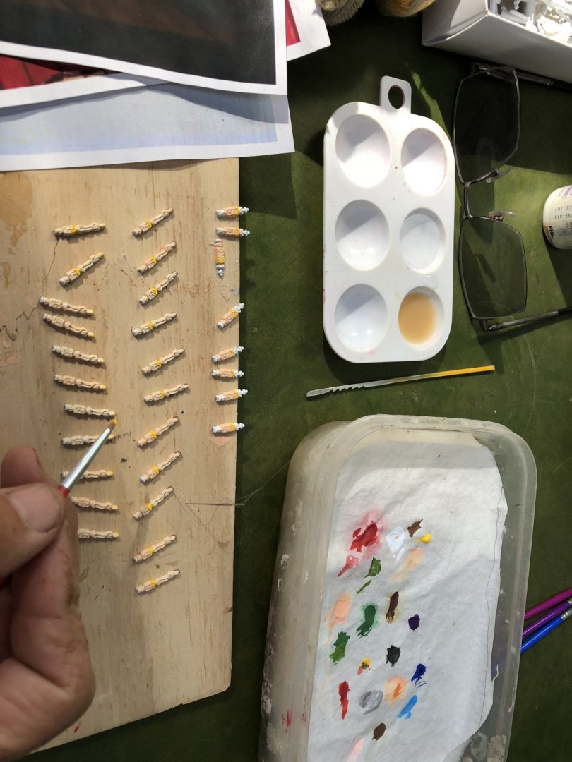
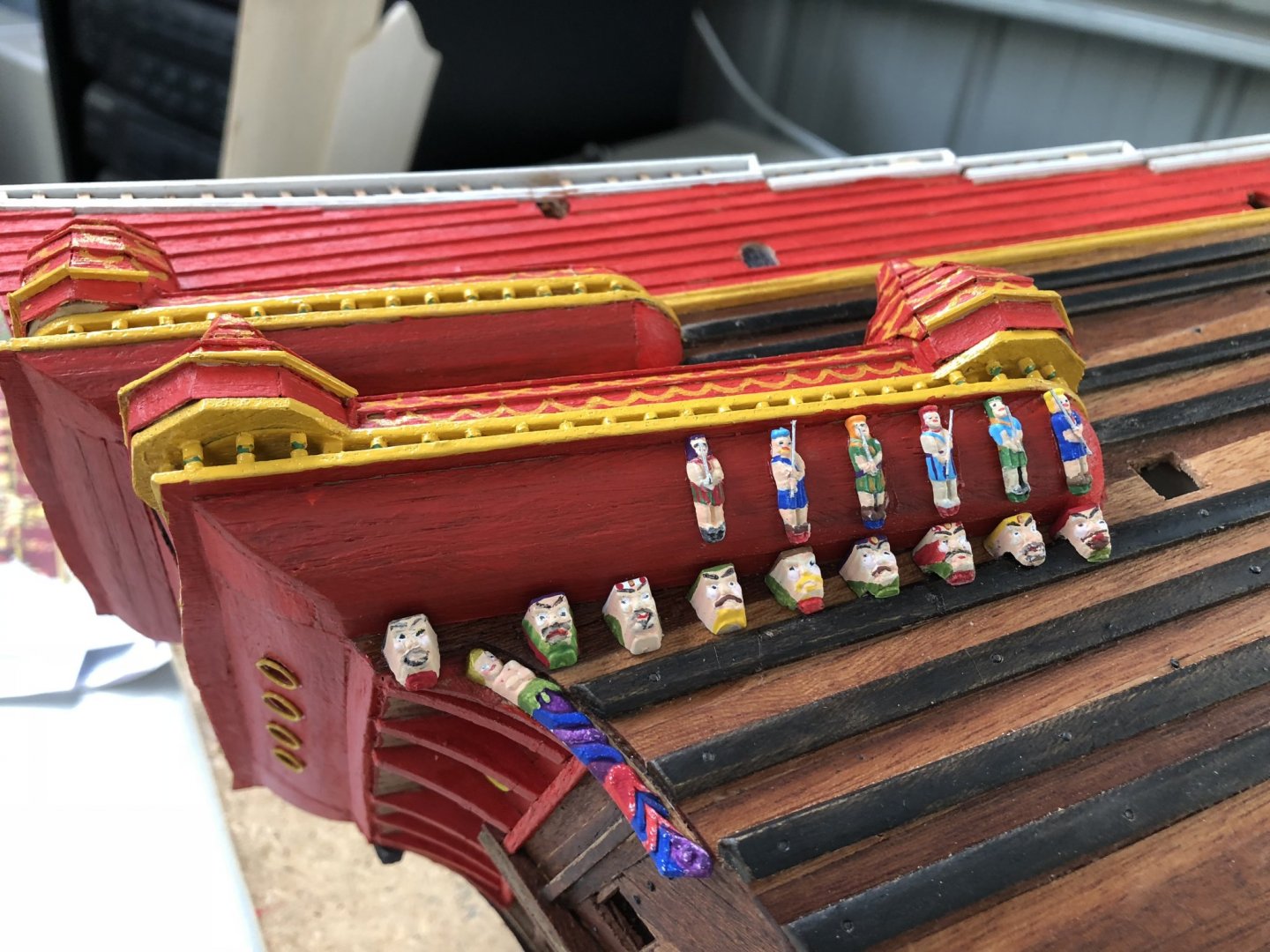
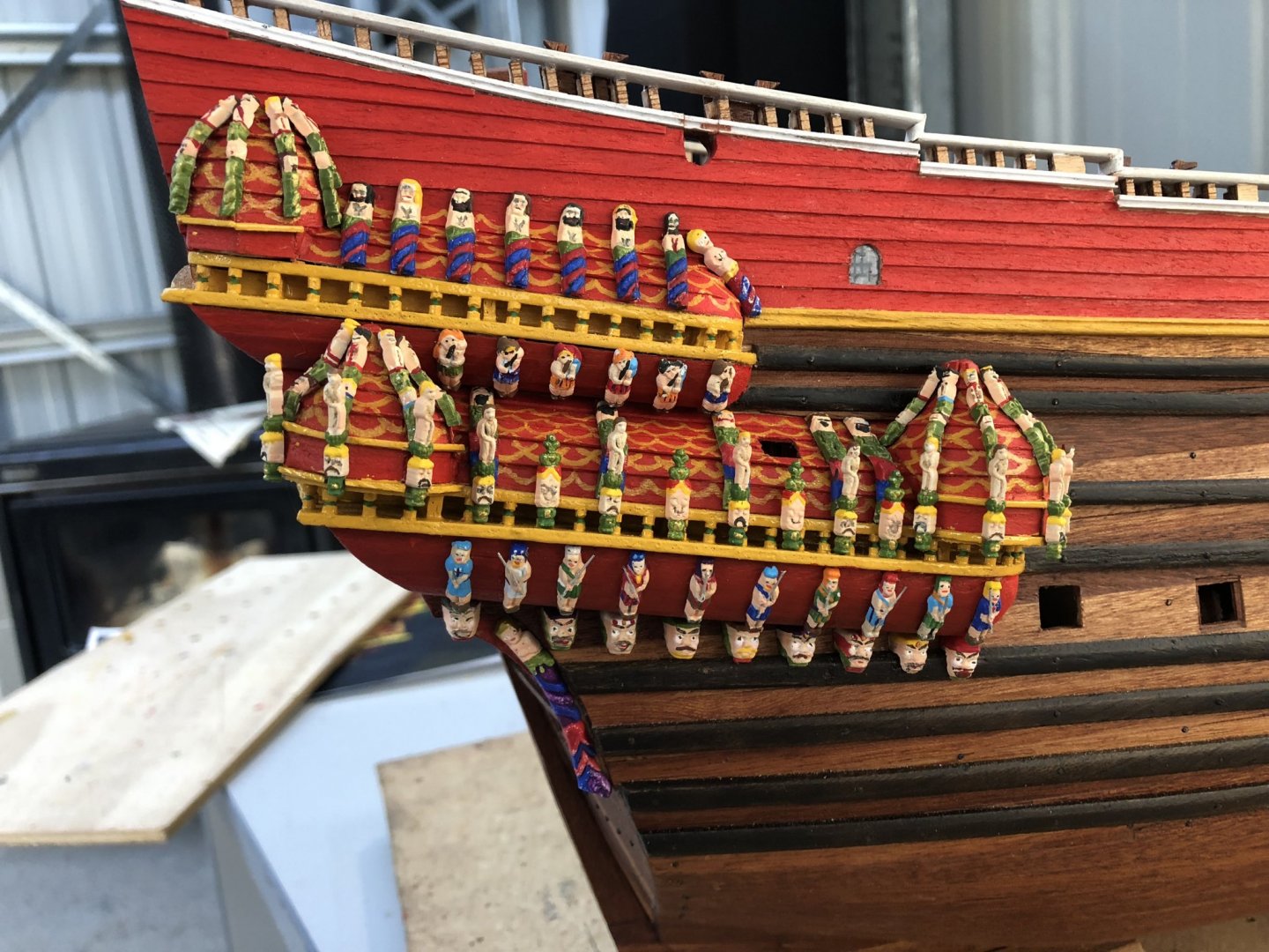
The galleries and topsides are now completed to a point where I can start dealing with the artwork/sculptures and their shaping and painting. There are two stages to adding the sculptures for the Billing Boat kit-supplied figures. Stage 1: Shaping Billing Boats supply brown, dense plastic mouldings of the various carved figurines. These had to be shaped to conform with the various curved surfaces they needed to be fitted onto (especially in the case of the galleries). In other locations (eg bow section, the Roman figures are applied without shaping, only fitting). After a number of trials on discarded parts of the same plastic (frames), I attempted to shape the plastic. These trials included experimenting with using boiling water, hot air from a hot air gun, a ski waxing electric iron (similar to a clothes iron, but my wife wasn't happy about using that!!), a candle (as the instructions describe to use) and a curved but temperature controllable electric soldering iron. Some of these methods destroyed the plastic, melting it, others methods made it only a bit malleable so when bent to shape, the plastic cracked. The best method I found was the soldering iron on about half maximum heat. I found I could slide the back, flat surface of the figurines around the curve outer face of the soldering iron and then I had about 10-15 seconds to place it on the ship where required and bend to shape. After this time, it cooled back to being rigid and inflexible. While the above method achieved the shaping I needed, one of the downsides (although this was an effect I noticed on ALL heating/shaping methods), was that the plastic slightly shrunk in size!! In some cases this was an advantage (when the space available on the model was tight), but generally the lengths of the figures fitted the ship for length so reducing size was an issue. The trick was to keep the heating to just enough to bend to shape, but not overheat to cause very much shrinkage. In general this worked OK, but there were a few disasters (over in excess of 200 figurines!!). Billing Boats provide only about the right number of sculptured carvings, so there was little room for error. Stage 2: Painting As said above, the supplied plastic was a dark brown. While the plastic took paint quite well, the brown is not a good colour when applying acrylic paints. So I needed to use a light, white undercoat to allow the best base for the overcoating. To minimise any loss of very small figure detail, I used a white spray-on undercoat while the figures were attached to their supplied frames. Below you can see an example of the plastic, supplied, unpainted figures in their frames. By undercoating the figures initially, this of course was pre-heating and pre-shaping. I found that the heating and bending in most cases did not cause the undercoat to come off or delaminate. In some instances there was a little cracking, but not too bad. So, with the undercoat relatively intact and the figures individually shaped, I could commence painting. My local supplier (and I live in the country, many hours from a large city), so the internet and mail postage is my normal means of supply), stocked Vallejo acrylic model paints and when trialled, these seem to give excellent, dense coverage, could be mixed effectively and dried quickly. I purchased a range of what I thought would be the most used colours (black, white, silver, yellow, red, two blues, two greens, orange, two browns, two flesh colours and purple). Not a huge range I know, but with mixing, it should be adequate. I reviewed a lot of videos and web descriptions on acrylic model painting. Let me tell you, there is a WHOLE NEW WORLD out there in painting of model figures. The painting is mainly targetted at gaming and painting figures for Warhammer and battles etc etc. The artwork is truly impressive with base coats, washes, highlights, dry painting and effects. If you are painting anything on your models, I urge you to spend a little time internet searching acrylic painting of plastic models/figures. It is a REAL EYE OPENER!!! some of the figures being painted is even a little risque!! So with my newfound knowledge about techniques and a bit of experimenting I started on painting Vasa figurines. I started with small figures and got more confident (there was no shortage of the number to be done!!). I cut the figures from the frames and then painted individually. Others I know have tried painting on the frames and then cutting apart. While this is a reasonable method, the cut of course has to be then touched up later, and when mixing colours, this is not always possible, so I opted for individual figurine painting in the majority of cases. I tended to use a colour and go randomly from one figure to the next in the collection using the same colour until done. The picture below shows this. I used a water-filled dish with baking paper sitting on wet sponge which acts as a palette and keeps the small amounts of paint useable for hours, even days, when sealed. This is a 'wet-method' idea I picked up from the internet research. You can see the water-palette in the photo here: A few different paintbrushes ranging from size 00 to size 2 were used and with fresh water on hand, cleaning of the brush and moving on to different colours or different parts of each figure was not a problem. For some of the figures, spears, swords or musical instruments are seen on the original ship carvings. After painting, I added some of these for effect. I found for spears and poles etc, some trimmed brush hairs painted black or silver were ideal for the scale when CA glued on. I show some of these for the lower starboard gallery as it progresses. A few different paintbrushes ranging from size 00 to size 2 were used and with fresh water on hand, cleaning of the brush and moving on to different colours or different parts of each figure was not a problem. For some of the figures, spears, swords or musical instruments are seen on the original ship carvings. After painting, I added some of these for effect. I found for spears and poles etc, some trimmed brush hairs painted black or silver were ideal for the scale when CA glued on. I show some of these for the lower starboard gallery as it progresses. The number of figures on each side is impressive. It takes a LONG time but the effect is just amazing. In nearly all cases, I have used CA glue to attach the figures. The next photo shows the nearly completed starboard galleries. Well, nearly half way!! Now to do the portside galleries, and then the stern. Time elapsed: 925 hours Regards, Peter G.
- 61 replies
-
- 5
-
-
- billing boats
- vasa
- (and 1 more)
-
Many thanks Patrick and Martyn. Lovely comments and much appreciated. To add my scalloping was a chore and took a long time!! I did not realise that the De'Agostini Vasa had raised scalloping. This would have made my job infinitely easier!! It would also make the linework finer and better defined. Thinking about it however, does that mean that the scalloped surfaces are moulded, and therefore plastic? I guess its hard to tell on the finished product, but the clinker timber planking used on the Billing Boat's kits gives a nice texture replicating the original ship well. I will have to look at the online De'Agostini instructions to see how they do this. Regards, Peter G.
- 61 replies
-
- 2
-
-
- billing boats
- vasa
- (and 1 more)
-
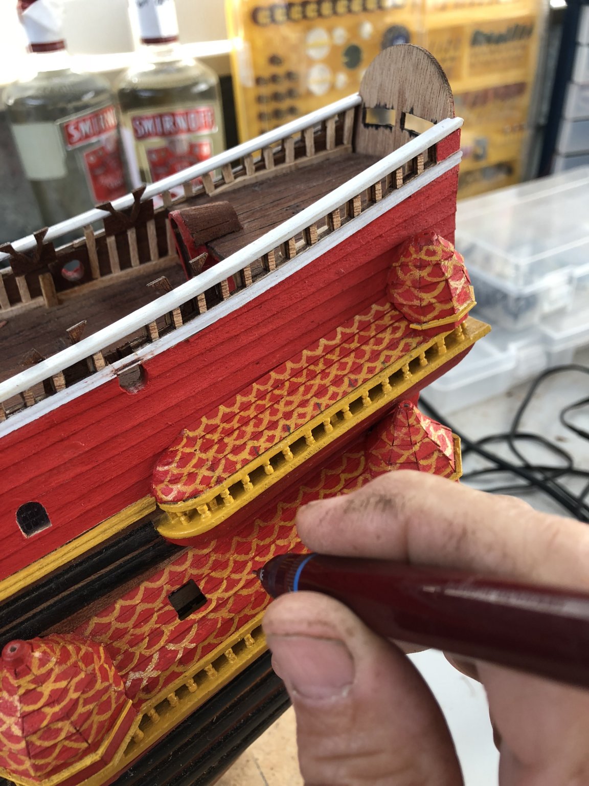
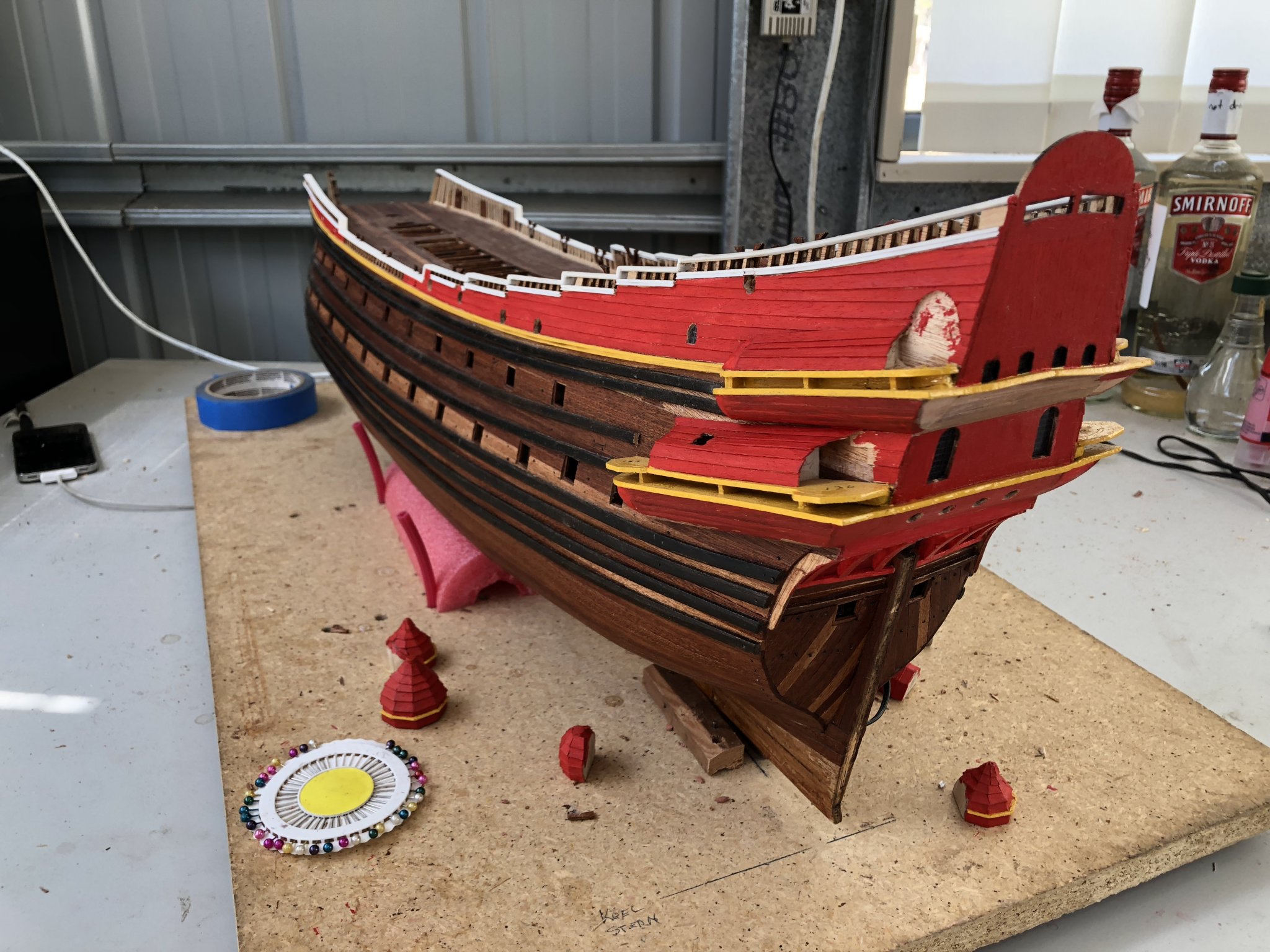
Many thanks Johnathon. The red and yellow were always going to contrast strongly. When the artwork is added, the contrast will be broken up a bit. To take a break from the stern and galleries, I turned my attention to the hold gratings. Billing Boats supplied these in the kit as laser-cut plywood. The ply was a relatively light brown which was not similar to the decking or darker mahogany timbers I have used, so I did a bit of experimenting with a mahogany stain and came up with a good wash (water based), which I then applied to the various gratings. These gratings were cut from the laser cut sheet easily, but the individual pieces of ply that had to be extracted from the 'holes' of the grating took a long time to be cut out and removed cleanly. While the plywood and laser cuts were relatively clean, the instructions described (by way of a picture), as to how to fit individual timbers in a criss-cross fashion to form gratings. I can only assume this is how earlier Billing kits had their gratings made. I have seen build of gratings made this way and while it is a lot of work, I think it probably creates a higher quality and more authentic grating appearance. Either way (laser cut plywood or individual, manufactured gratings), they have to be better than plastic, which I also suspect (from comments in other Vasa builds) were used in some model kits of the ship. To increase the detail on my gratings however, as well as the stain, I also scribed the timbers and cut through the top layer of the plywood along each timber. This gave the look of individual timbers having been used for the grating vertical and horizontal wood and in the end, looks quite good. I show a picture below with the three stages of modification (the originally cut out laser plywood (left), the stained and scribed grating (centre) and the finished re-stained finished grating (right): The next task I decided to do while I had good access to the newly painted galleries, was the painting of yellow contrasting 'scallops' along the gallery upper surfaces. This is not something I have seen in many Build Logs, but it is present on the famous Berlin Vasa model, the recently researched De'Agostini model kit and the ship as drawn by Bjorn Landstrom (in his Vasa book of 1988 - and before the current research on the ship). Although I am not sure of its authenticity or appearance on the original ship, it does add a look that I quite like. This feature had to be done before any artwork sculptures were added so now is the right time. Below I show an image of the Berlin Vasa and its distinctive scalloping along its galleries. As I have now decided to try this (on a 1/72 scale model - silly me), I had to come up with a way of creating these scallop lines with suitable paint. I figured that if the end result was not appealing, I could repaint the gallery surfaces. So, how to paint the fine lines that would be required. I tried a number of paintbrushes (size 0 and 00), but I could not get a consistency that could be maintained. Also a paintbrush with the curves of the scallops was really hard to shape. I then thought, how about a paint pen. You can buy these and they are really good, but I could not get one that had a fine enough felt point that didn't thicken after a couple of scallops being drawn on the relatively rough timber surface of the clinker planking. Is there another type of pen that would allow the paint to flow, but could apply its line when held fractionally above the surface of the timber. My old professional drafting days came up with the idea of a drafting pen. In the back cupboard (after some searching), there was my Rotring drafting pen set and all the protractors, scale rulers and curves!!!. I realised that the thickness of drafting ink and that of paint were considerably different, so I needed to do some experimenting with diluting the paint (with turpentine as it was an oil-based enamel). I trialled some acrylics, but the cover was just too thin and transparent, so it had to be oil-based enamel. After a lot of trials and experimentation, I finally came up with a relatively strongly diluted mix of enamel paint and turps which flowed through the fine 0.2 mm nib of the Rotring pen that I found to work the best. Below are some photos of the pen in use and the final product. Although not perfect everywhere, I think the effort and effect is quite good. You have to also take into consideration that there are a LOT of sculptures to be added to the galleries and turrets so many of the poorer scallops will be hidden. One other thing I added too, which can be seen in the above photograph, are the large number of infilled vertical, turned timbers that lie between the two galley base frames. These I turned out of toothpick wood and then cut to the required length. They also add some detail that is seen on the original Vasa. Time elapsed: 805 hours Regards, Peter G.

- 61 replies
-
- 7
-
-
- billing boats
- vasa
- (and 1 more)
-
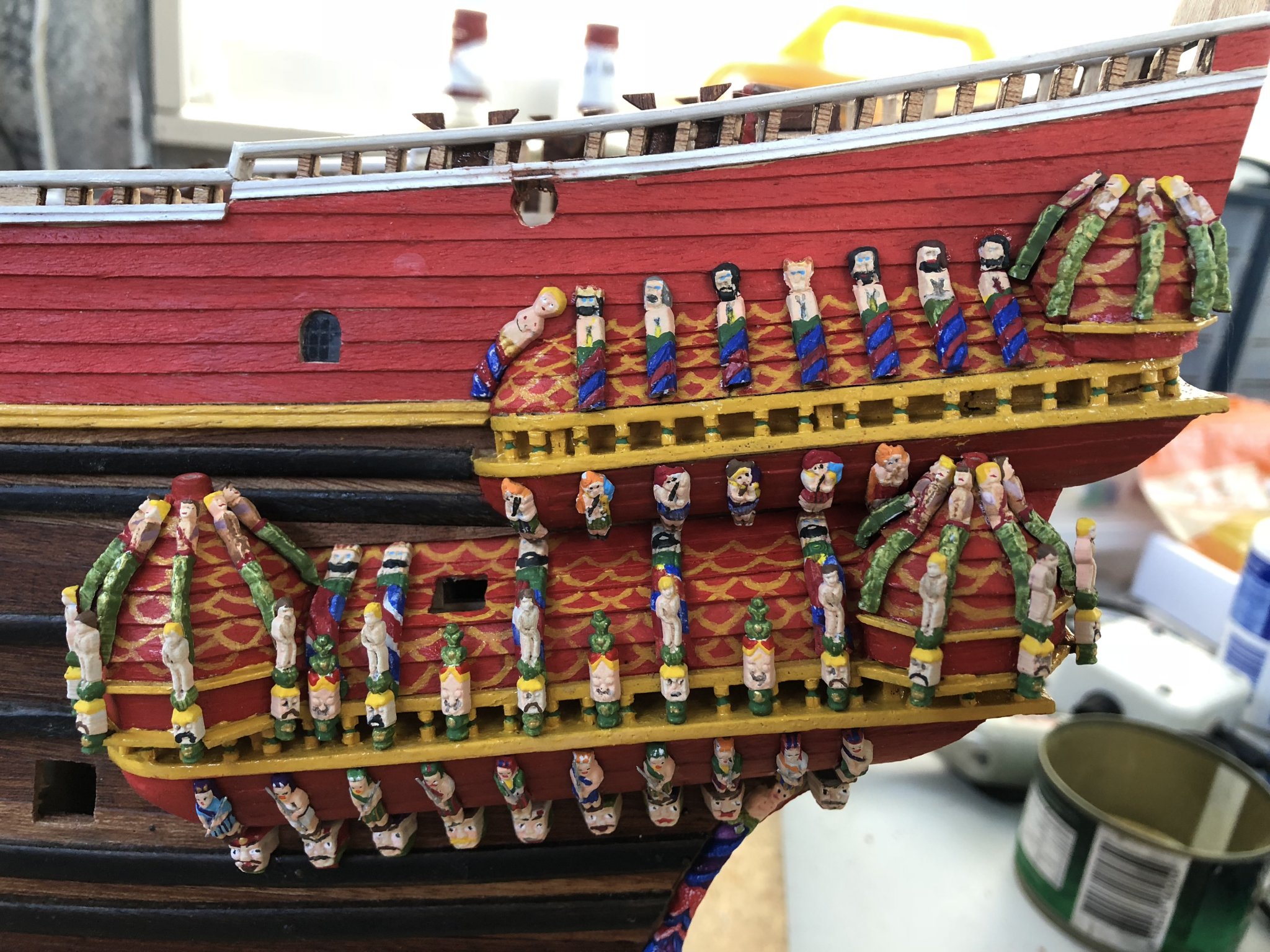
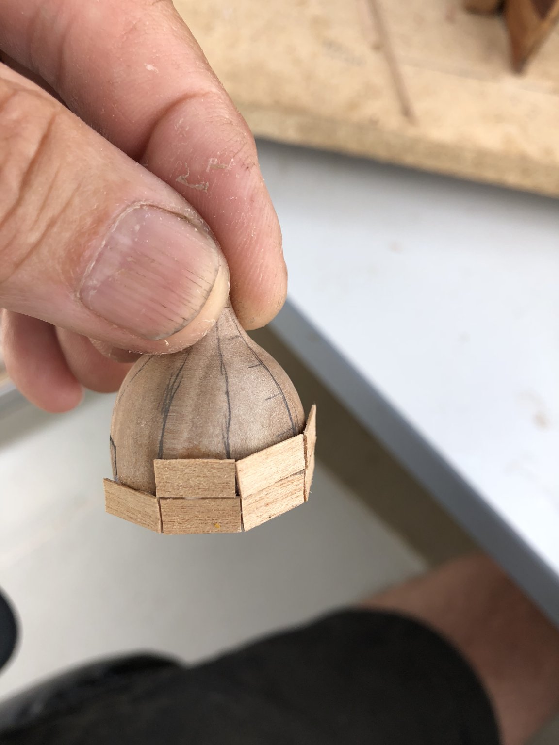
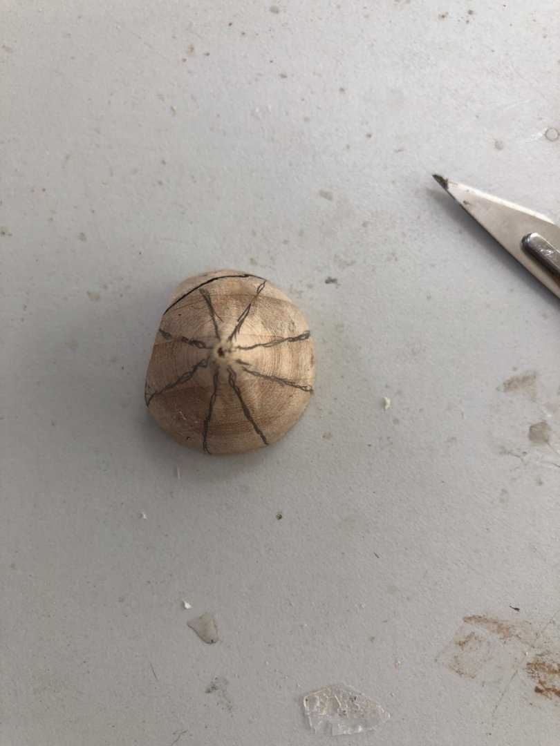
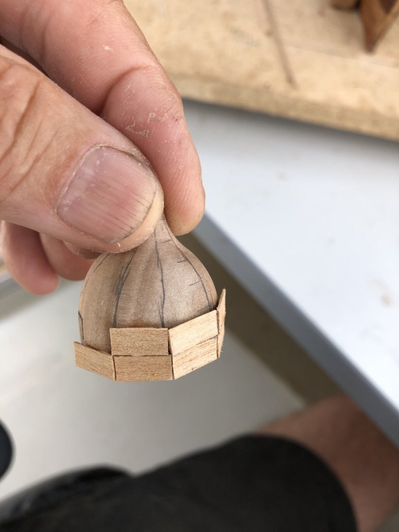
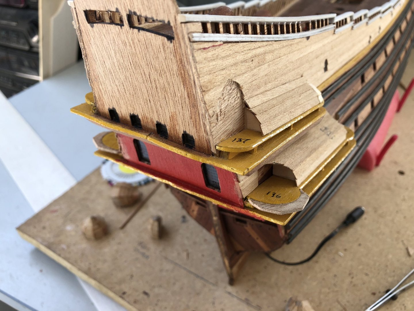
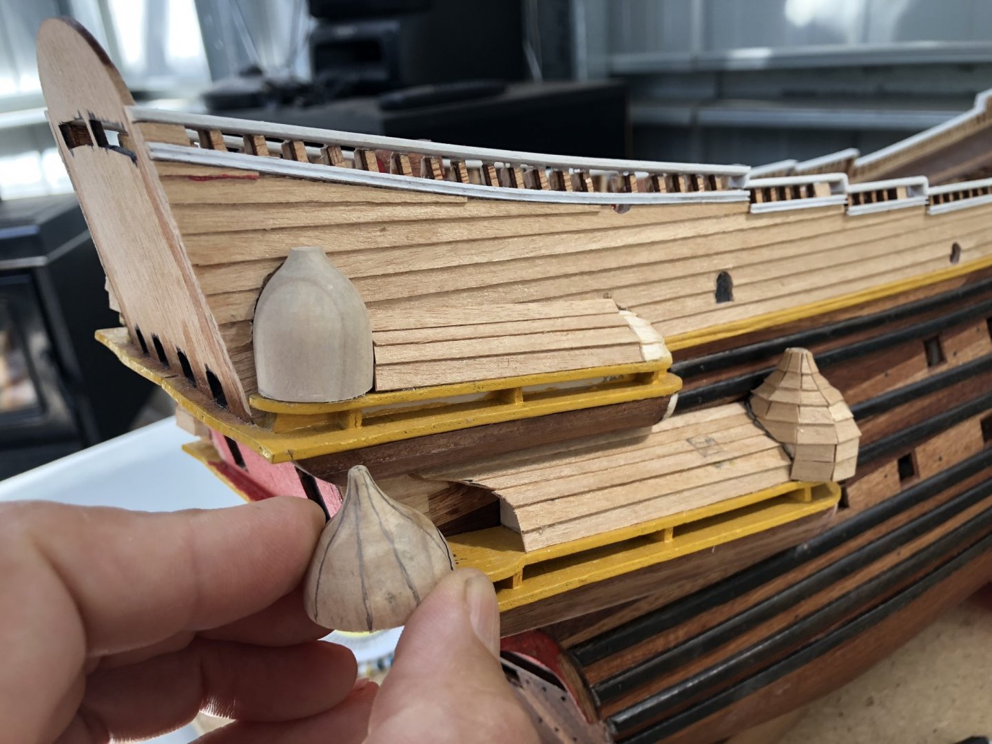
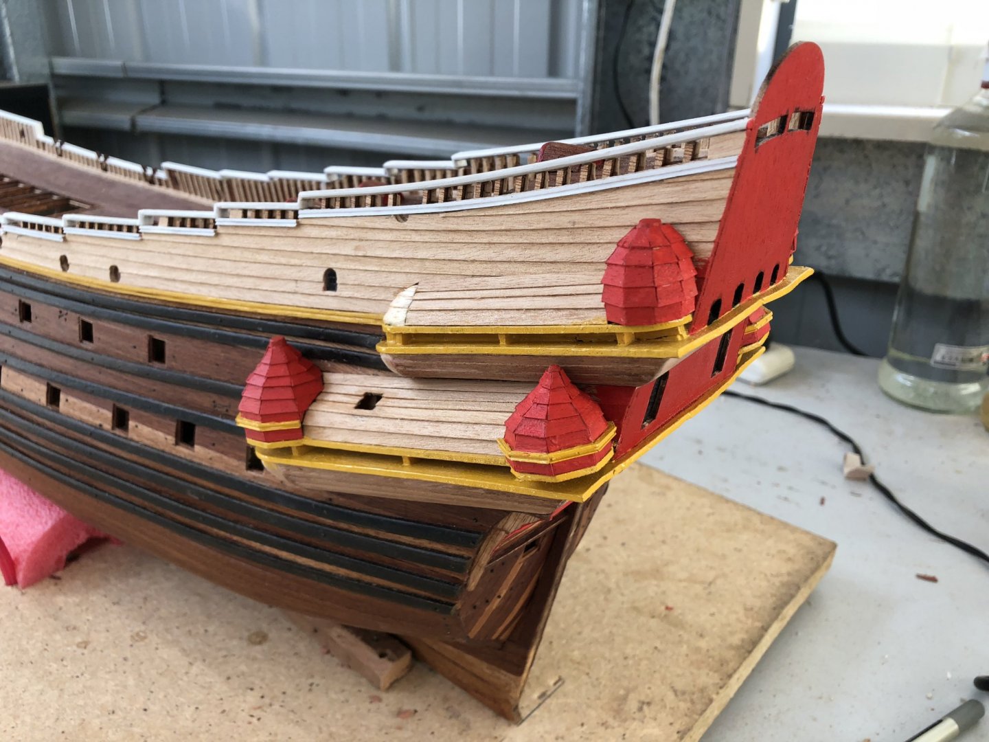
The individual turrets have been shaped and I am happy with their position, angles and clearance for the brass ornaments at the top. I had to cut the tops of two of the turrets slightly to reduce their height a little bit to make them fit correctly. You also have to cut into the topside clinker planking against the hull to allow the turret to sit against the side of the ship in their correct position. Initially, the sides of the turrets were shaped to sit correctly and fit against the ship (as described above) and then each turret had to have clinker planking covering it. The joins for edge plank end need not be absolutely perfect because these joins are covered by shaped figures eventually, but they nevertheless have to be reasonably neat. Below are a couple of pictures where I have started adding the planking. I divided each turret into octagons - eight sections (you can see the approximate pencil markings of these to indicate the ends of the plank cuts. I have started planking at the bases of the turrets and then slowly worked my way to the top for each individual turret. On the ships sides, the clinker planking removed and allowing the turret to sit against the ship took some careful cutting. I also had to mark each turret to position it correctly with the created location on the gallery base as each was unique and could not be fitted anywhere else. Finally, I located the turrets when I was happy with their clinker planking, location and clearances. Surrounding each lower galley turret at their bases, is a lower strip of timber which seems to extend one of the upper wales on the hull. In the pictures I have seen in the Vasa publications and the model in the Vasamuseet, this strip was shaped (with a central groove, like the topside wale) and painted yellow. Because of the contrast of the gallery colour to be added (red), and this yellow, I felt it was best to paint while the turrets were off the ship. So, I painted these and the clinker topside planking, before gluing the turrets finally in place. The next images show this. This completed the addition of the turrets to the galleries and nearly completes the galleries structure. Considerable work will be required to add the ornamentation and artwork, but the galleries are now in place. Phew. Time elapsed: 740 hours Regards, Peter G.


- 61 replies
-
- 8
-
-
- billing boats
- vasa
- (and 1 more)