HOLIDAY DONATION DRIVE - SUPPORT MSW - DO YOUR PART TO KEEP THIS GREAT FORUM GOING! (Only 72 donations so far out of 49,000 members - Can we at least get 100? C'mon guys!)
×


SardonicMeow
-
Posts
333 -
Joined
-
Last visited
Content Type
Profiles
Forums
Gallery
Events
Everything posted by SardonicMeow
-
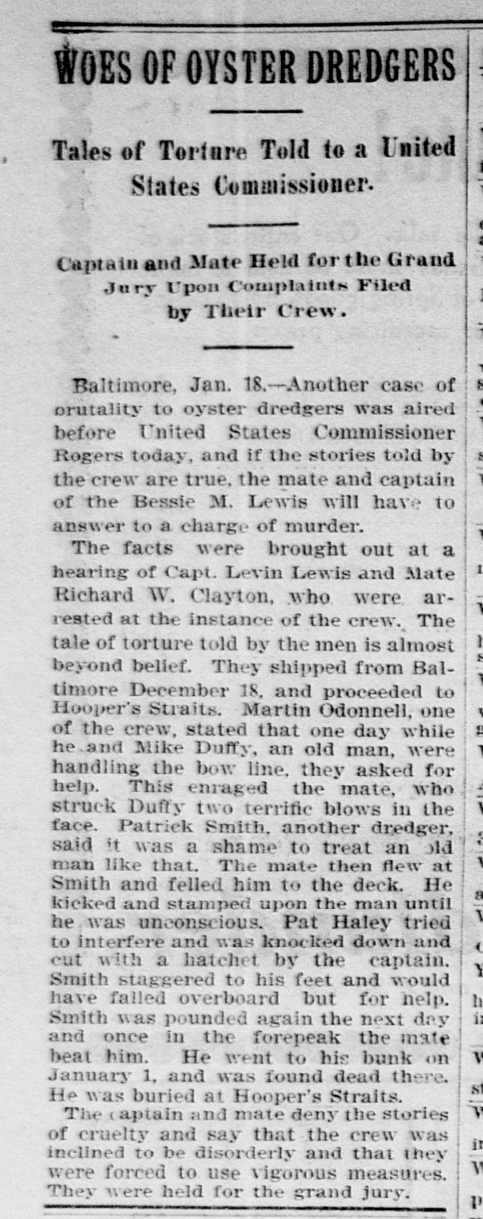
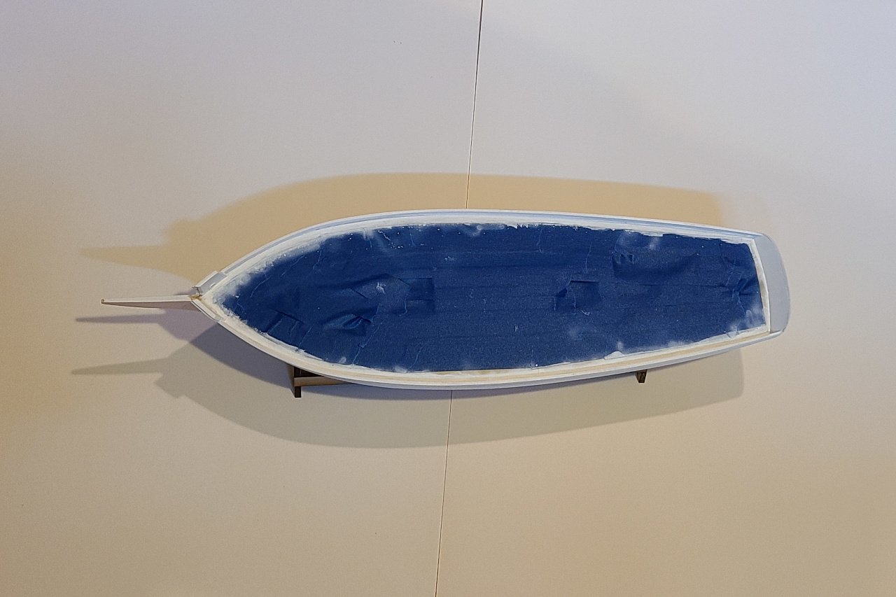
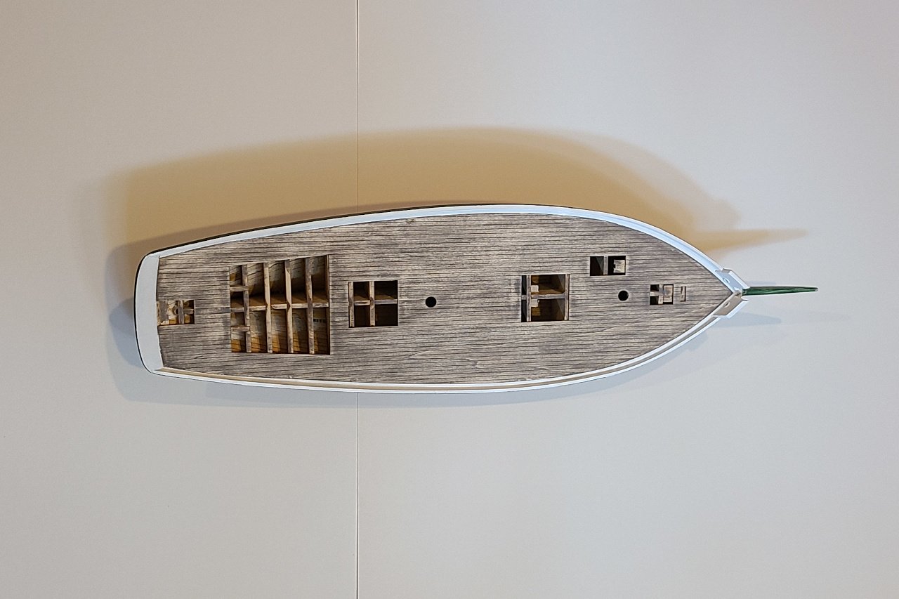
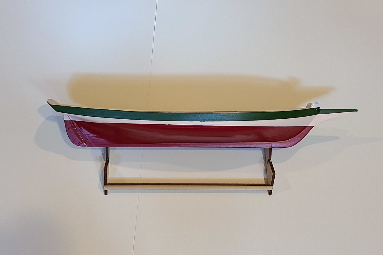
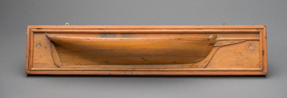
 Painting a pungy Pungies were traditionally painted green, pink, and red, as shown below. The waterways and rails were painted white. Above: Half-hull model of the Amanda F Lewis, constructed by William E. Geoghegan circa 1954 Image source: The Mariner’s Museum, retrieved from https://catalogs.marinersmuseum.org/object/CL24945 For most of her life, the Amanda F. Lewis was painted this way. However, in the 1930s, her owner was unable to find the traditional pigments, and she was painted grey above and white below. The painting in the first entry of this build log shows this paint scheme. In theory, I could have a historically accurate model if I painted it the same way. But, of course, the traditional colors are too nice not to use. The green color was called “bronze green”, sometimes described as bottle green. It was mixed from dark blue, raw sienna, and vermilion. I found a paint using chromium sesquioxide pigment that is sufficiently close. The pink was described as “flesh” color and was made from white, vermilion, and raw sienna. For some reason, no one sells paint in “pungy pink”, so I had to mix my own, and I followed the traditional recipe. I started by adding a little red to white, and ended up with a pink that looked like strawberry ice cream. After adding the raw sienna (much more raw sienna than red), I achieved a color that I think is pretty close to authentic. The red color on the bottom of the hull was “vermilion”, and I found a crimson color that looks good to me. The deck was taped off and everything received a coat of white. Then pungy pink on the bottom. More tape was added and the green and red were painted. (And I forgot to take pictures at this stage.) After all the tape was removed, and some touch-ups applied: View from above And from the side
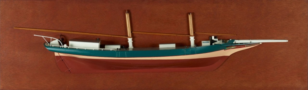
-
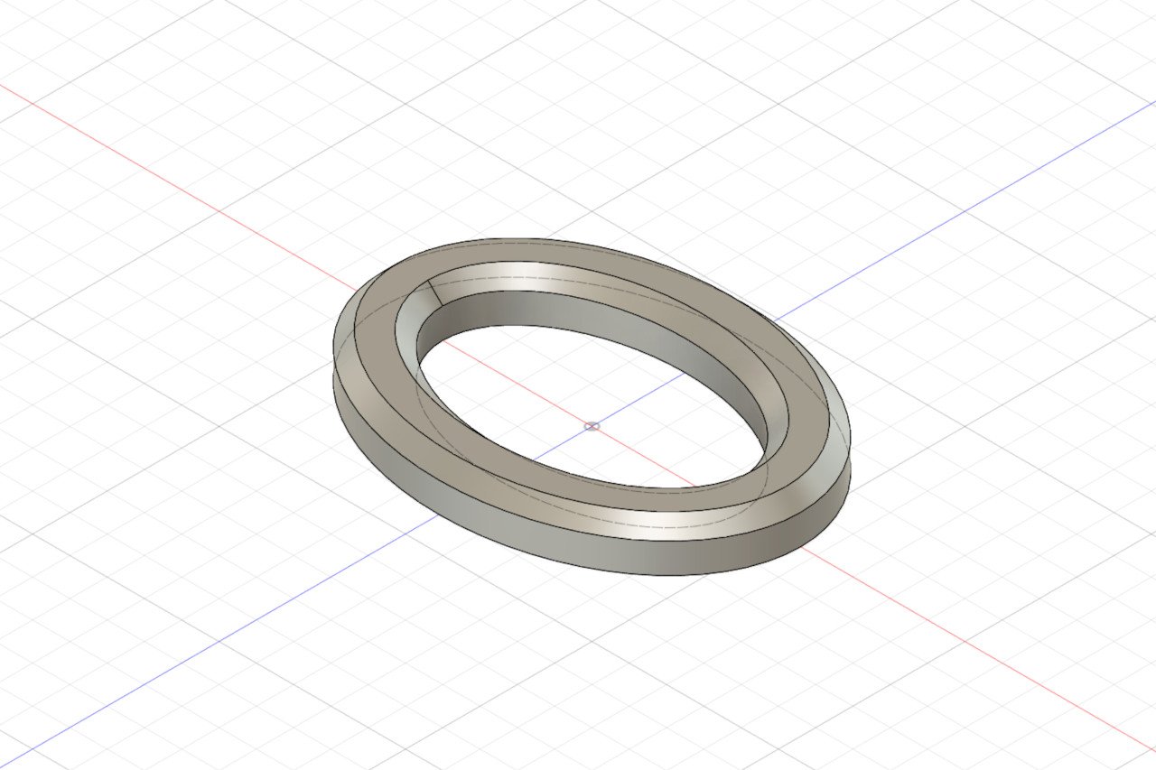
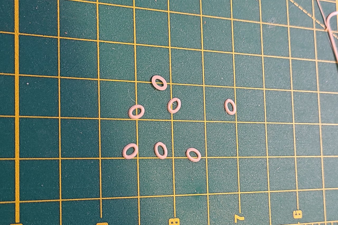
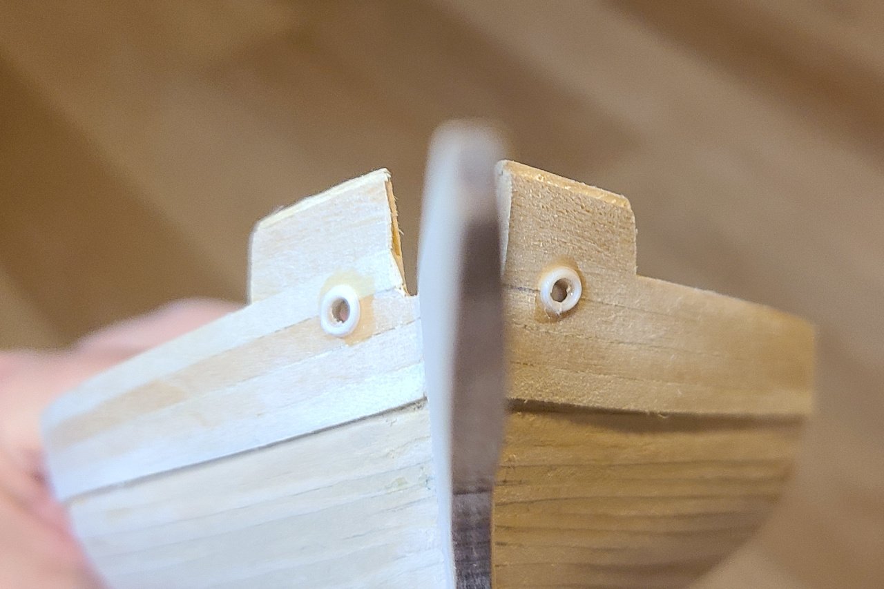
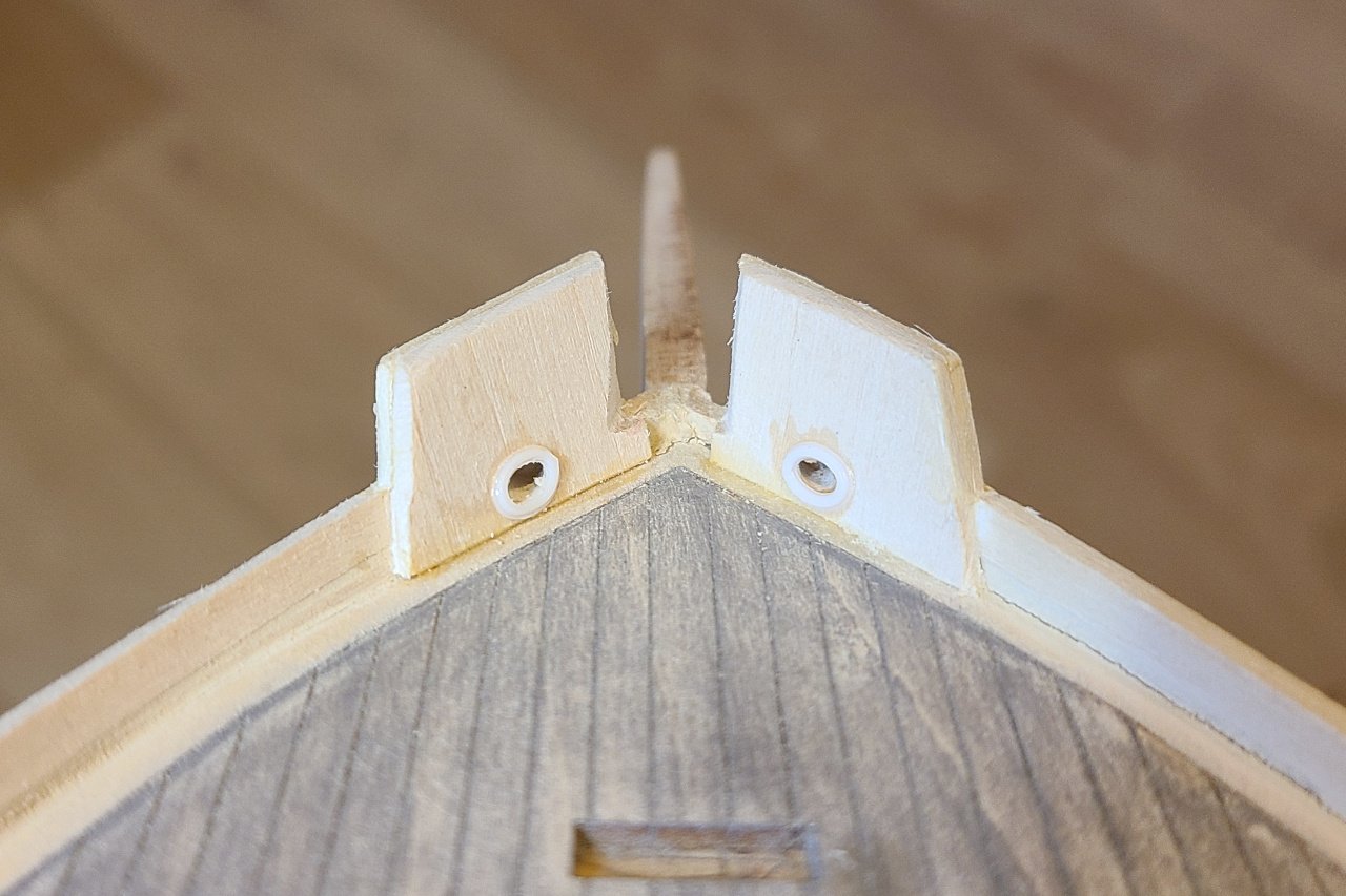
The hawse holes were drilled through. And a 3D part was designed to go on the hawse holes. I printed multiple because there are sometimes a few duds. Glued in place. And on the inside too. Pins were added to the rudder. And straps to make the pintles. 3D printed gudgeons. And all of it put together. All of this will be painted, so color and glue stains don't matter.
-
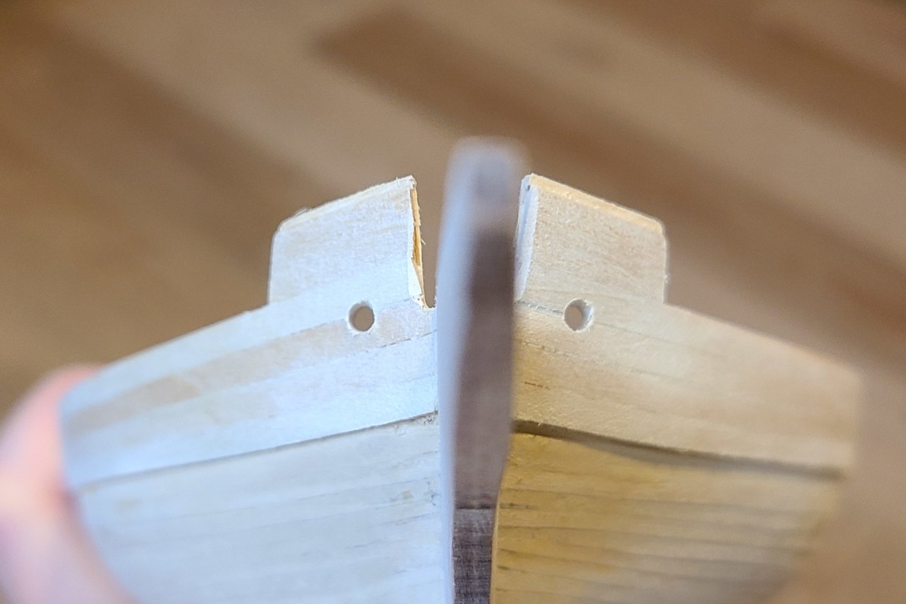
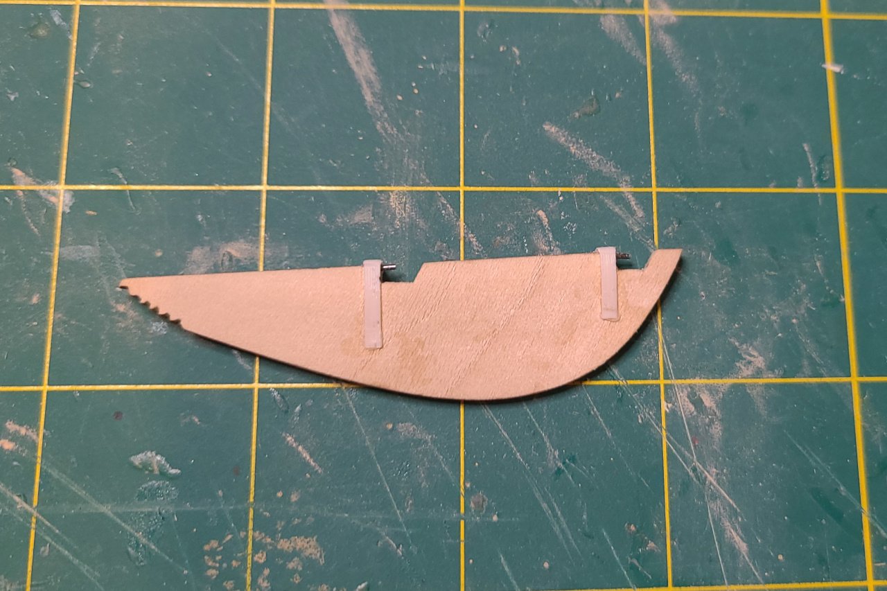
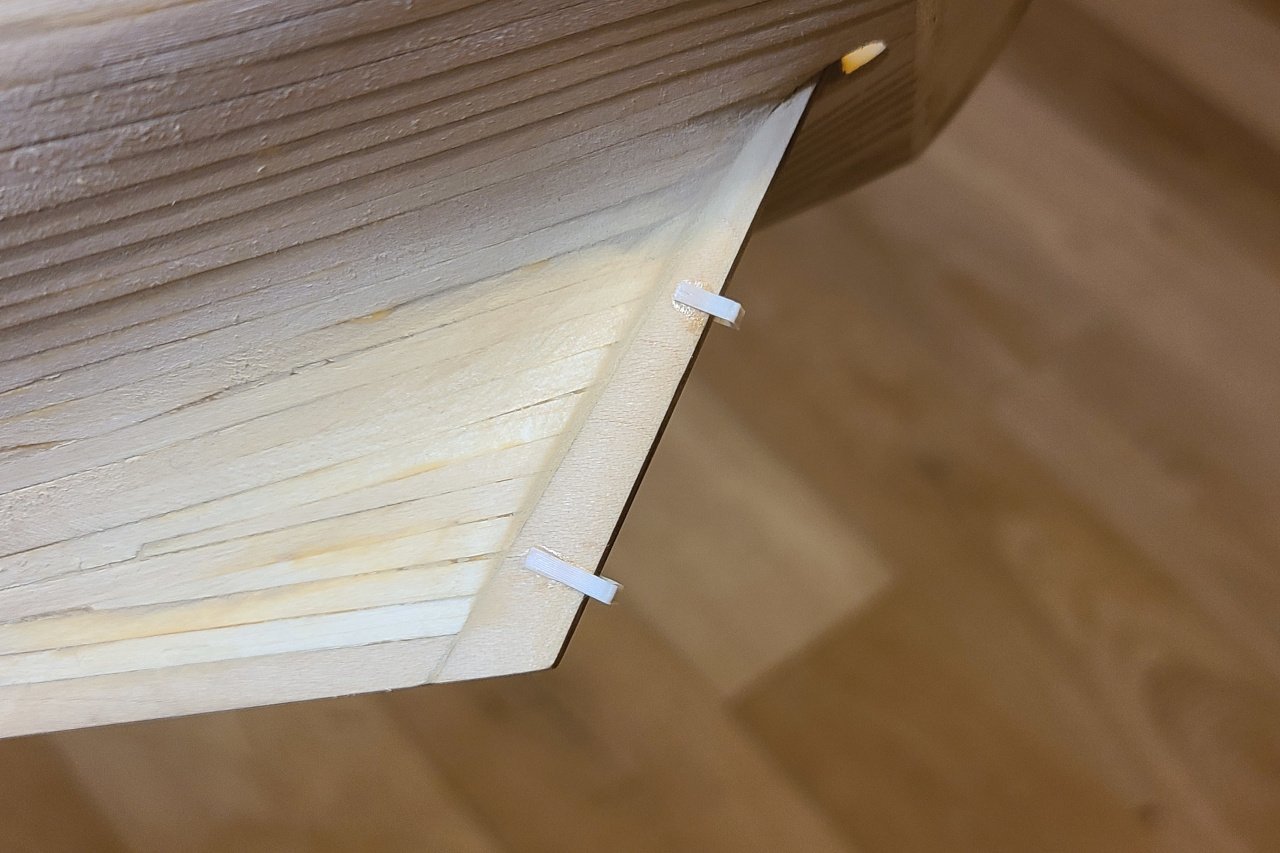
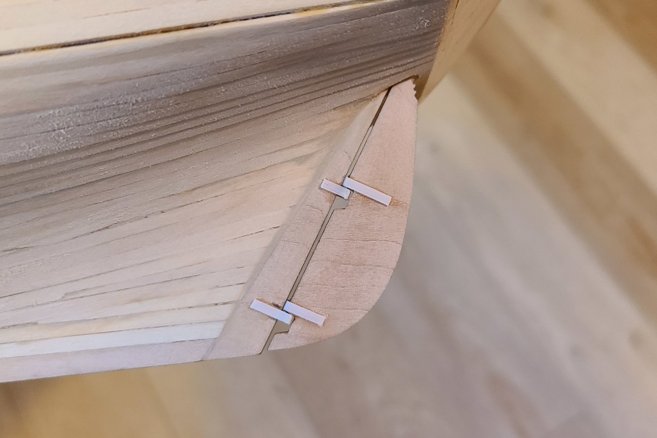
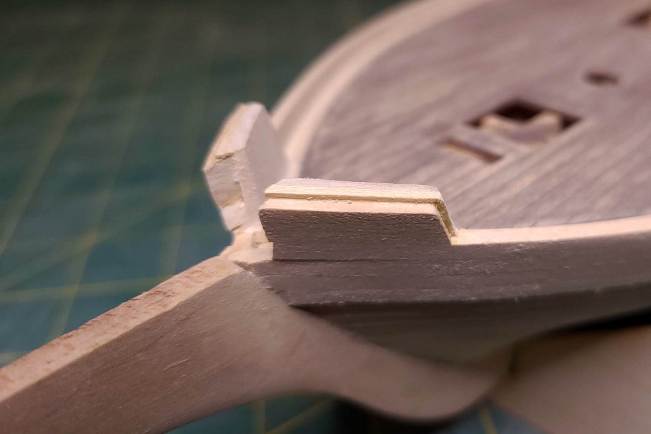
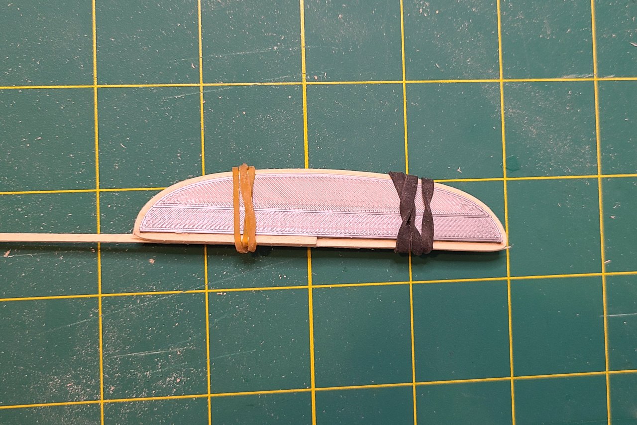
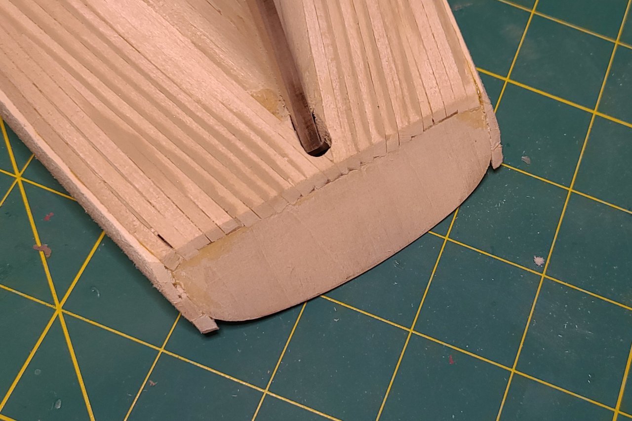
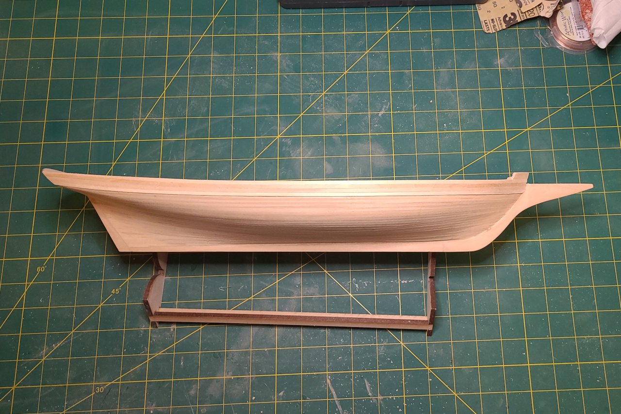
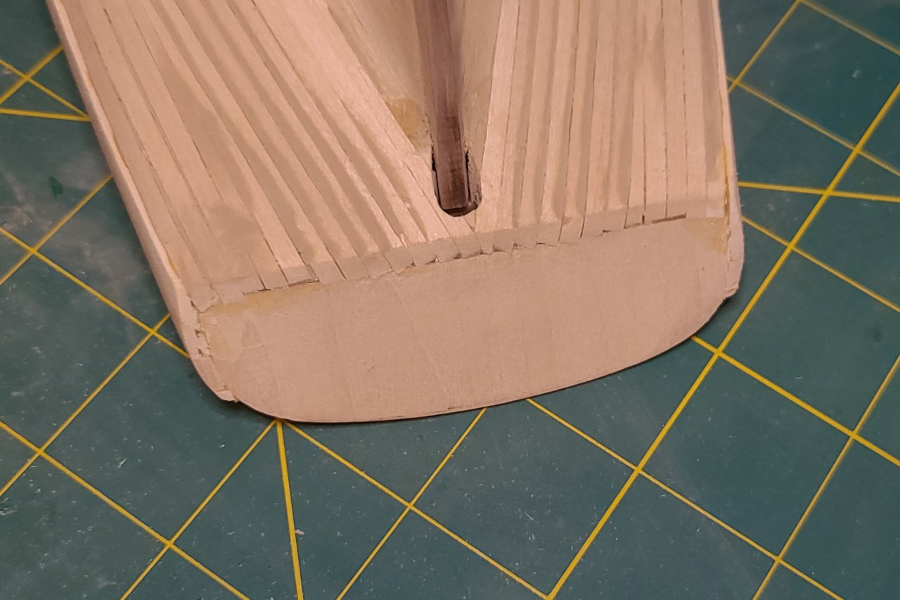
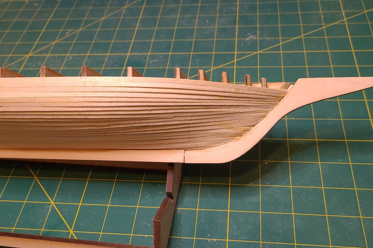
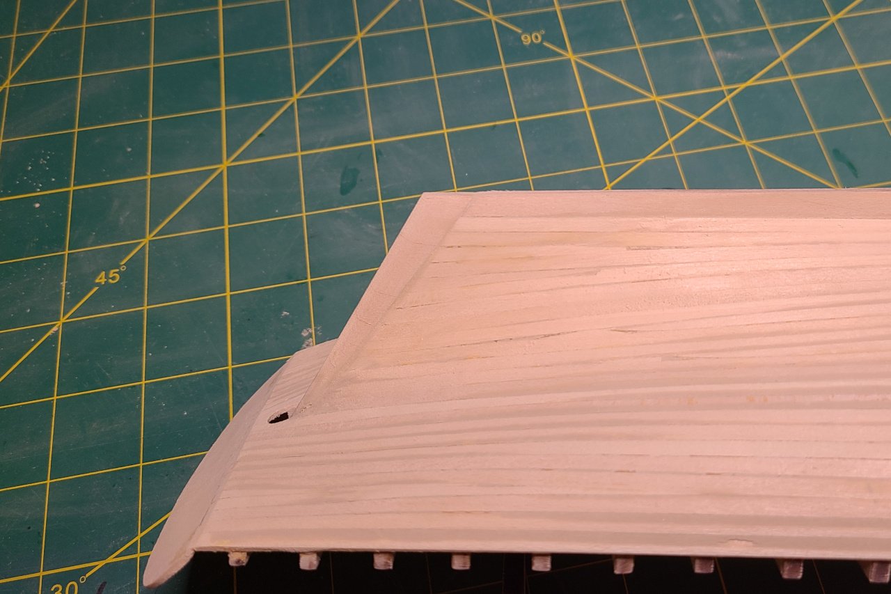
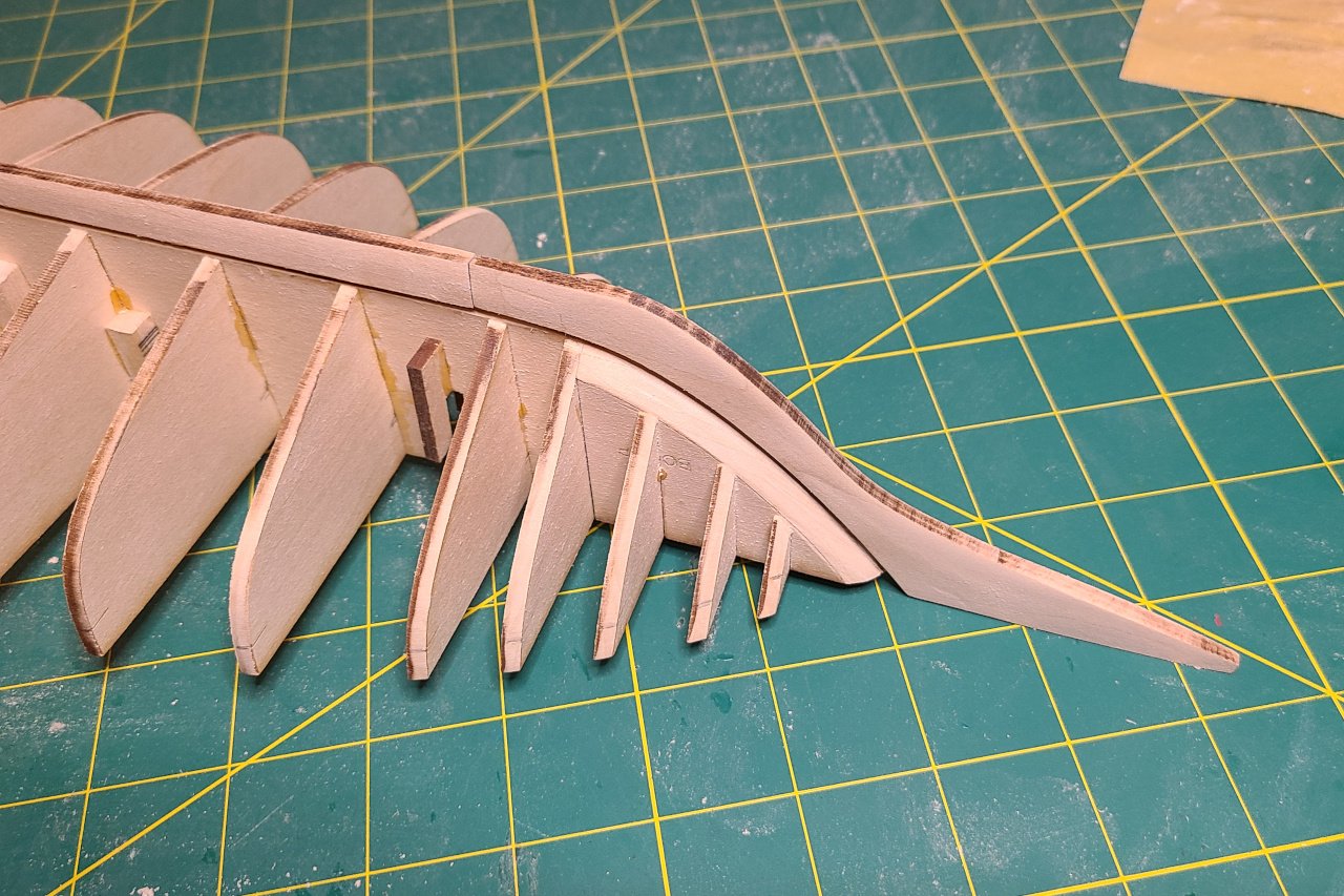
A small update. I built up the area at the bow. And also addressed the issues with the stern. Have a look at my last update to see what was wrong. I needed to add a thin strip along the edge that would add enough material so that the entirety of the stern would be smoothly rounded. Since I already had the shape of the stern in Fusion, I created and 3D printed a piece to use to form the strip. A 1/16" x 1/16" strip was soaked until it became flexible, then it was bend around the 3D printed piece and allowed to dry. After gluing the piece on, adding some filler, and sanding, the stern now has a nice shape.
-
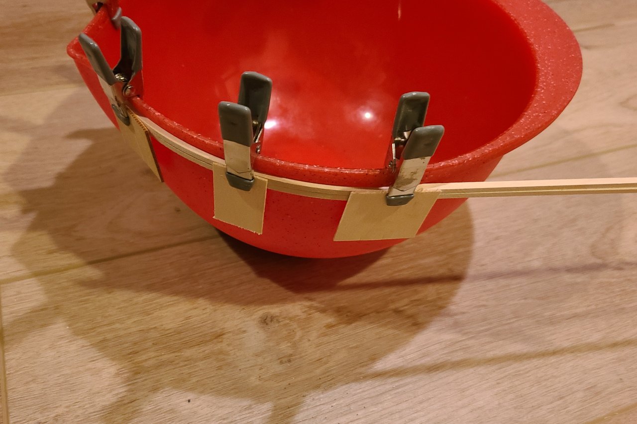
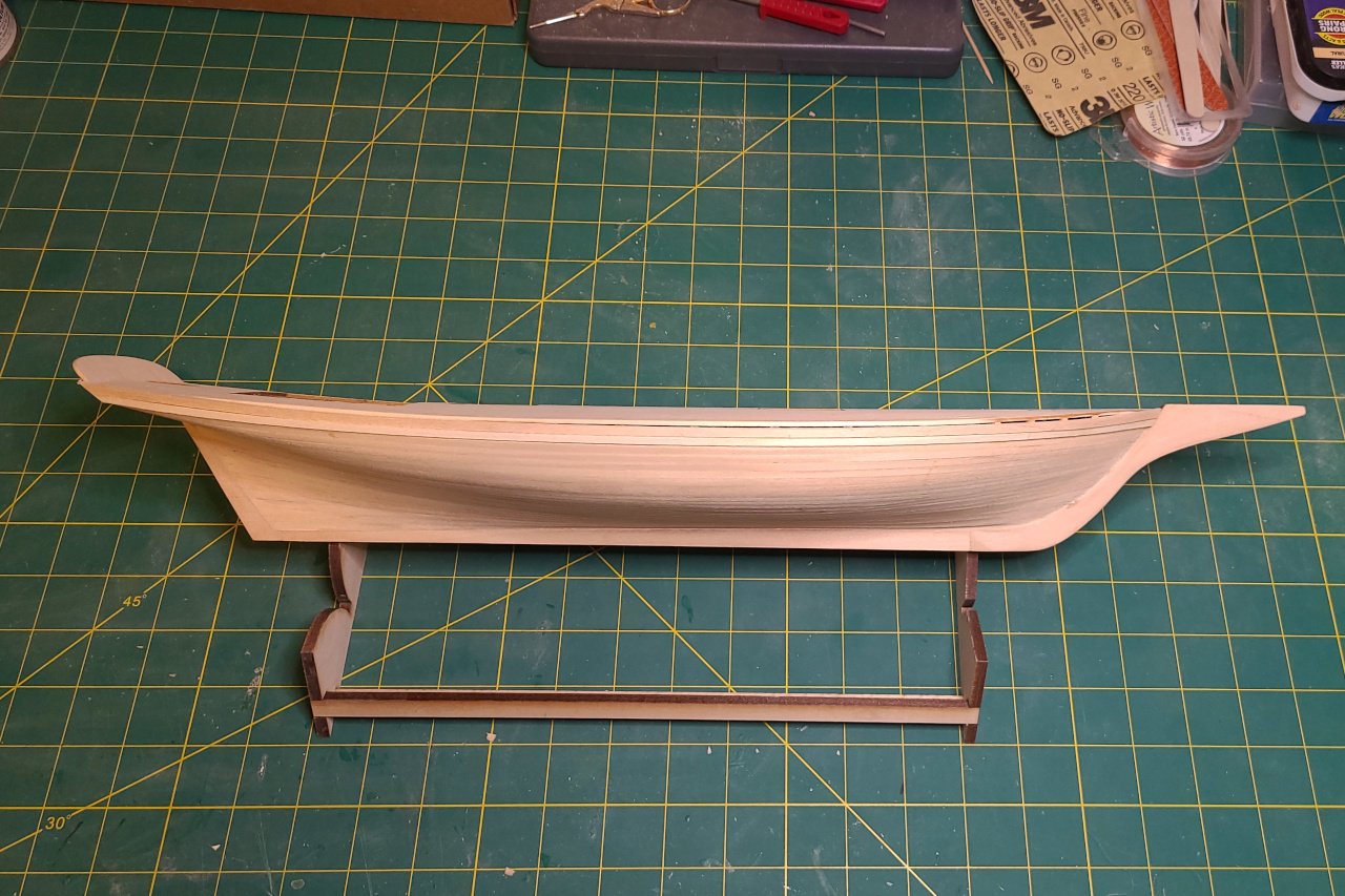
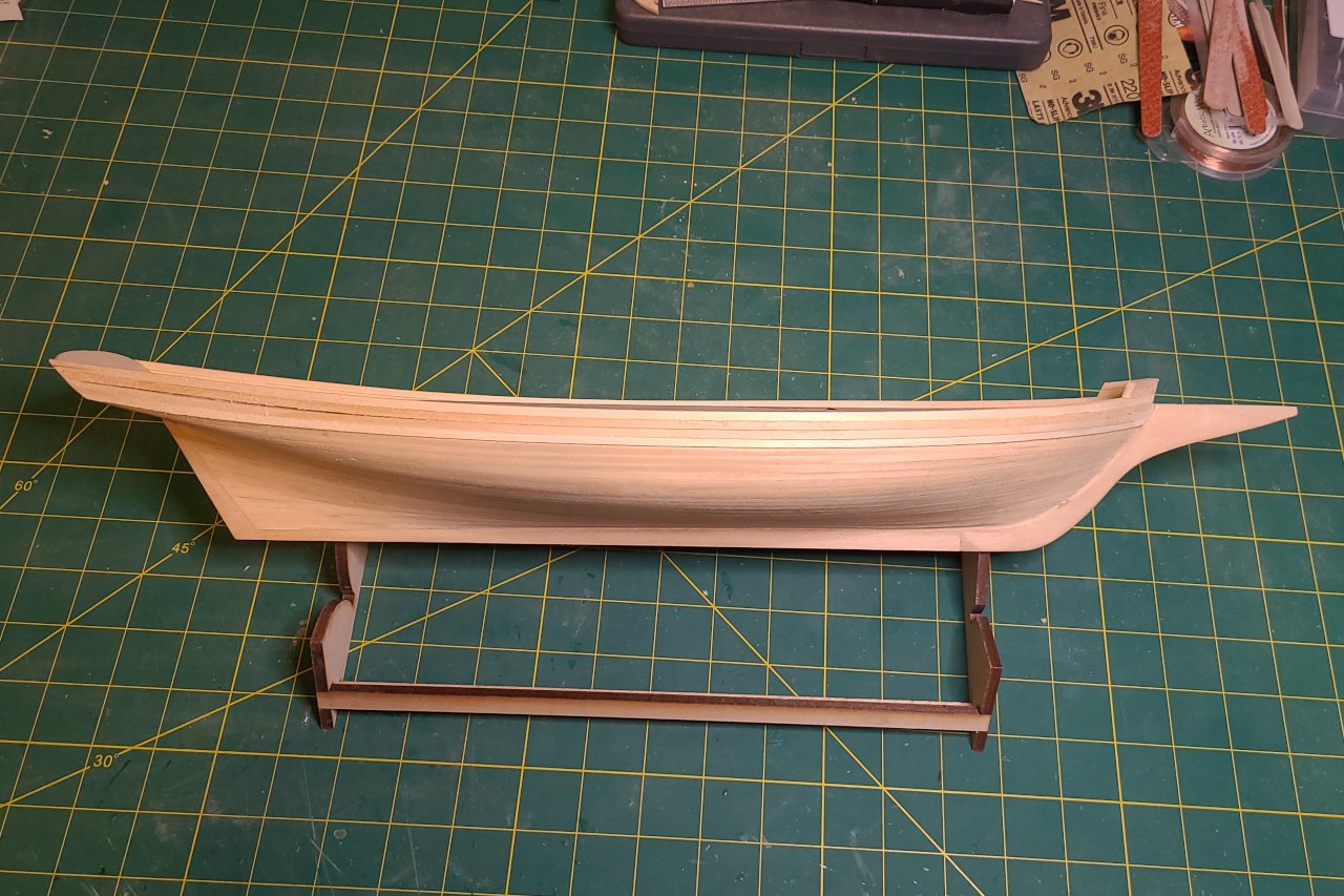
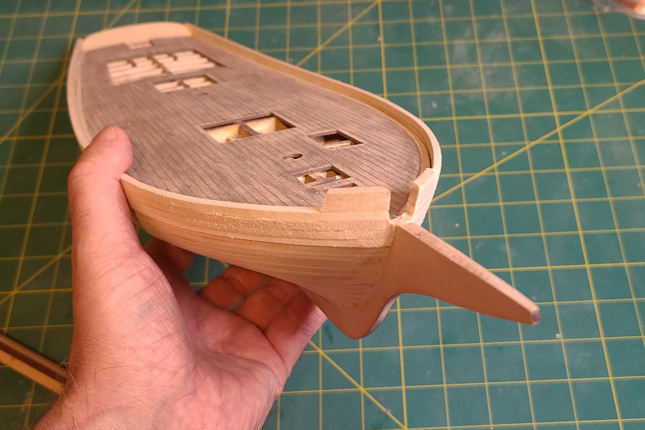
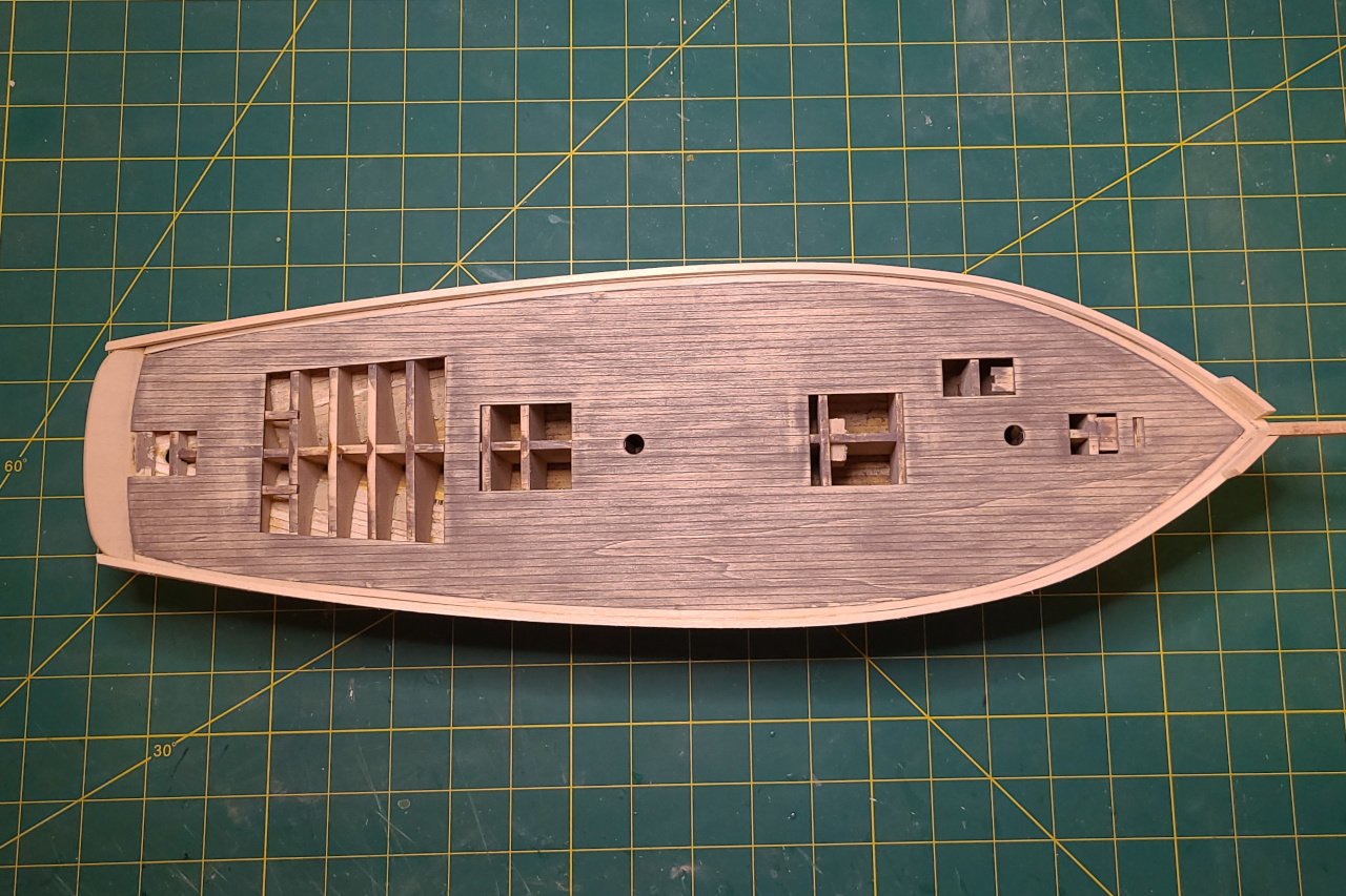
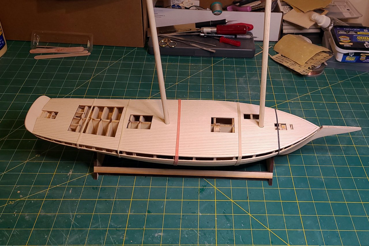
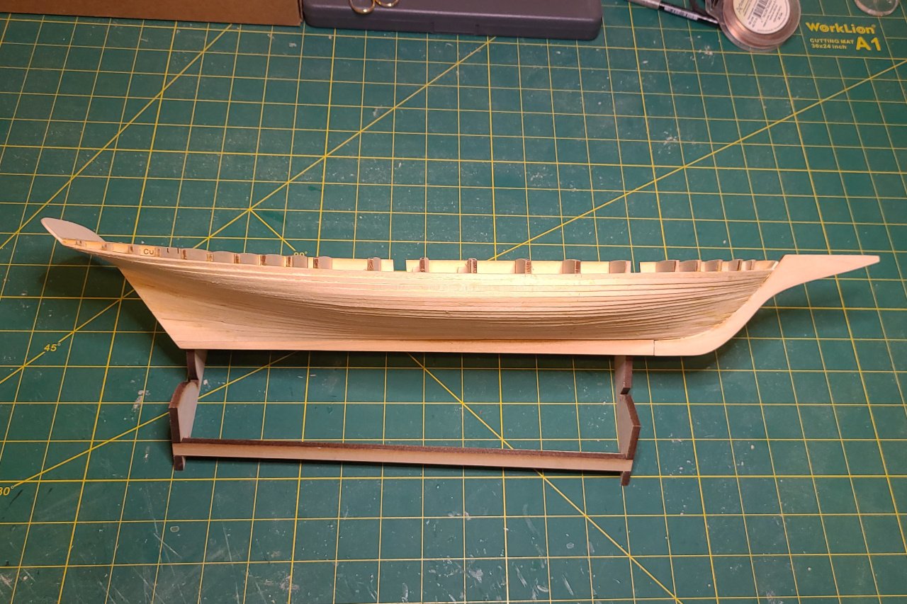
Now it's time to plank the hull above the bends line. The planking needs to be thicker, so I used 1/8" x 1/8" strips. They don't bend well on their own, so I soaked them in water and clipped them around a bowl to encourage the most extreme curve needed. Two planks added... And four planks... There is a bit of a gap between the planks aft. (And other imperfections not visible in these pictures.) These bits were added at the front that reinforce the hawse holes. (There is probably a name for them, but I'm not aware of it.) The stern has issues. The thick planking just added runs too high and will need to be reduced. And the whole stern needs to be more rounded. Also, I think the piece I fashioned is too short. After wood filler and hours of sanding, things are looking better. The stern is improved, but still needs work. I'm going to try to bend a thin strip to fit around the top of the stern. Somehow... I also stained the deck, then tried to sand it back to give it a weathered look. It's not too bad. The biggest issue is that, because the deck was laser scribed from a single wood sheet, there are some natural patterns in the wood that continue across planks. Next time: Adding some hull details and getting it ready to be painted.
-
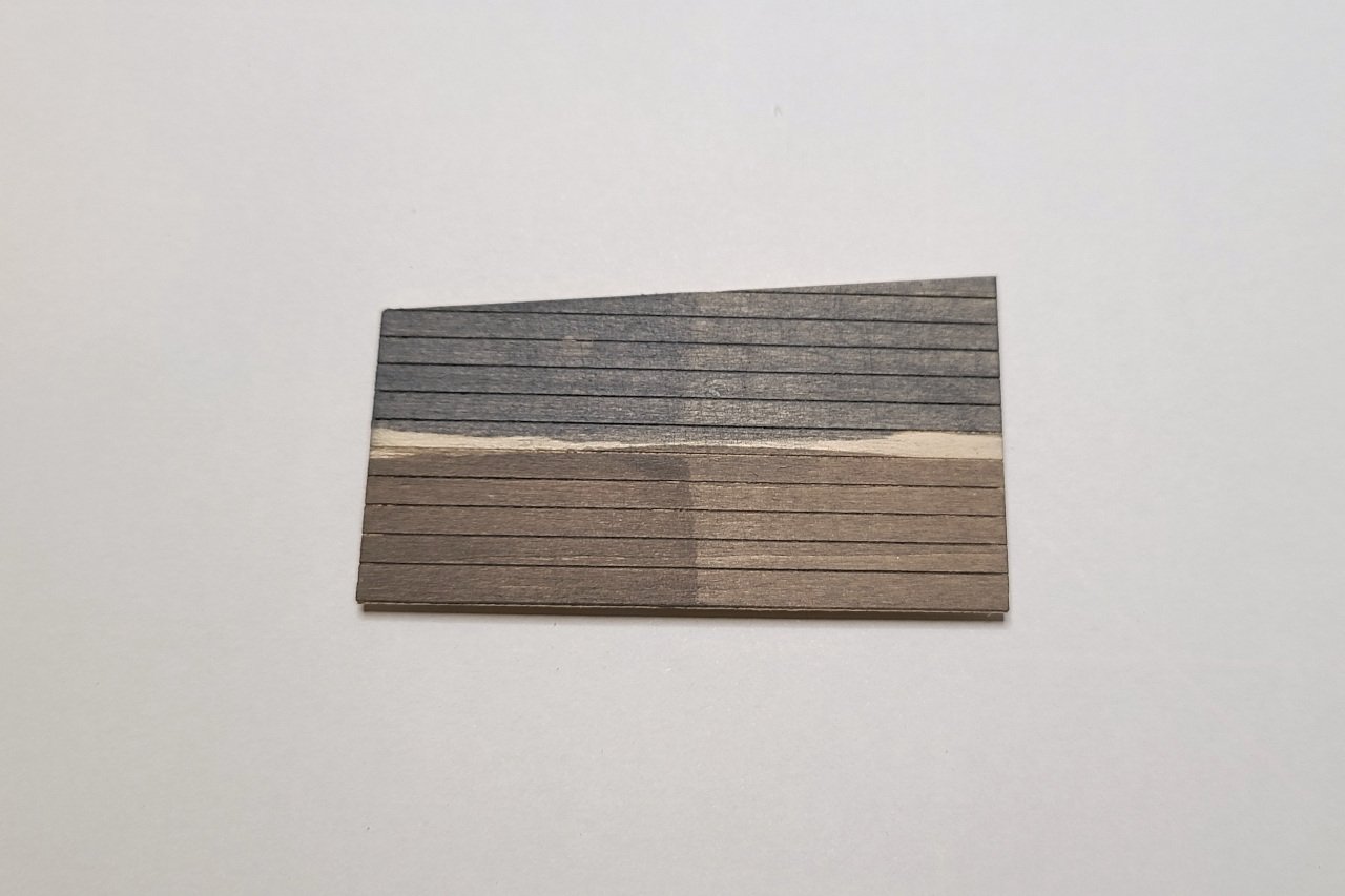
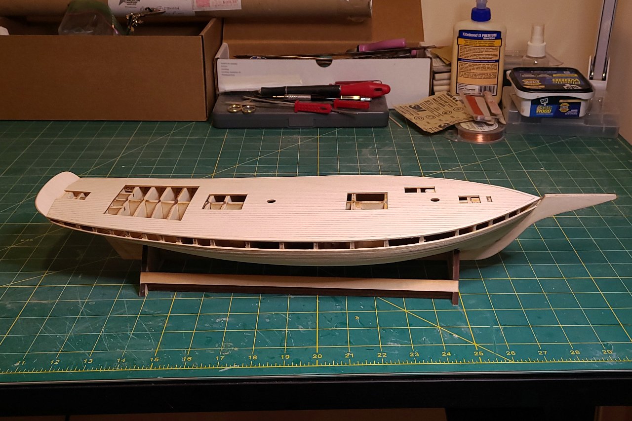
I wanted to get the deck in place next, as the sides of the deck would add more surface area to attach the bends planks. Rather than planking the deck, I chose to laser cut a scribed deck. First I had to determine the pattern for the planks. Looking through pictures of schooners of the same location and era, I found that straight planks were as likely as planks that follow the curvature of the bulwarks. I did not find any examples of nibbing. I decided to go with the simple option of straight planks. The design was laid out in Fusion, including the waterways and cut outs for the various deck features. And it was taken to the laser cutter. (This was the second version. I cut one originally then discovered a flaw in it later.) The deck was aligned with the hull by inserting dowels into the mast holes. Then rubber bands held the deck in place while the glue dried. And the deck is in place. I want the deck planks to have a weathered look. I picked up two stains that looked likely to work. The top is "weathered gray" and the bottom is "classic gray". A solid coat is at left and at right was the result after wiping the stain immediately after application. None of these is exactly what I'm going for, though the result at the bottom right is closest.
-
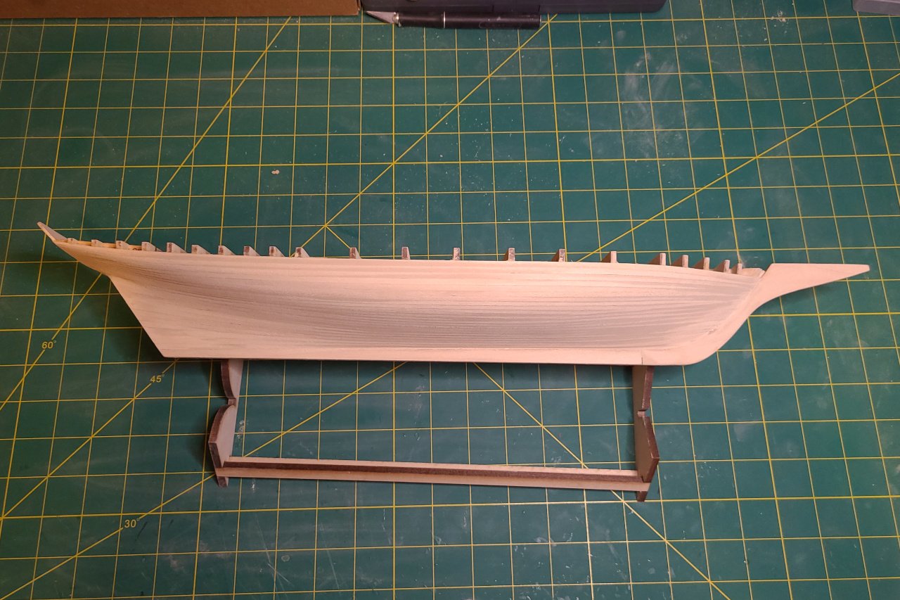
Planking of the hull was finally completed. The planking was quite clinkered in spots, especially here at the bow. Fortunately, wood filler exists. After a generous amount of wood filler and lots of sanding, the hull is pretty smooth. The stern post was glued on and a few gaps were filled in.
-
I listed pungies built by Joseph W Brooks, but he built other vessels too. The schooner Mattie F. Dean was built by him, but wasn't a pungy. There is a painting of the Mattie F. Dean on the Mariner's Museum website. Can you see what non-pungy features it has? I'll have to think about this. There are some flaws in my laser cut patterns that I've had to work around. I'm a little hesitant to give them out.
-
Planking of the hull continues. In Fusion, I designed the stern piece. It was not worth the trouble to go get it laser cut. I just printed out the pattern and then cut it from 1/16" sheet. The strake immediately below the "bends" was planked. If you look back at my laser cut patterns, you'll see where the location of this was marked on the bulkheads. Getting this strake in exactly the right position is important, so that the bends (which will be thicker) will run correctly. Now I'm planking the remaining space to complete the lower hull. I have family visiting this week, so work will be on hold for a little while.

-
Thanks, Jerry. I have updated the post to use the correct term.
-
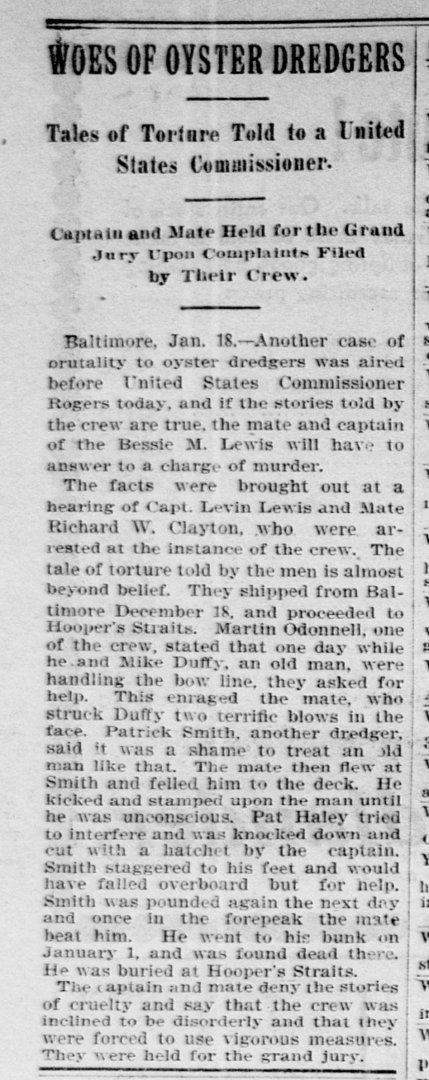
I couldn't find an account of what happened to Lewis after. However, I did find that Lewis was arrested for the incident described below. (Washington Times, 19 January 1898). His sentence was 2 years in jail and a $100 fine. Lewis died in 1902 at age 41.
-
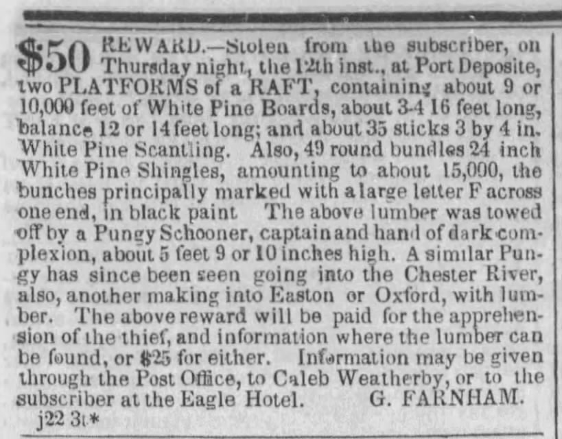
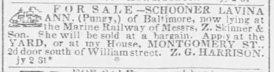
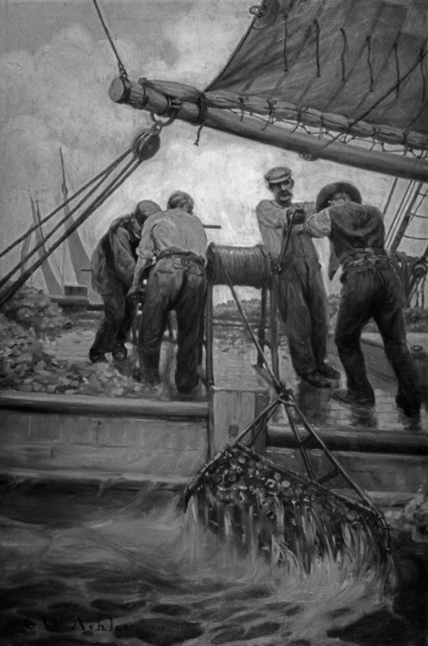
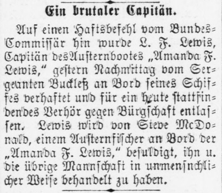
Historical Interlude 1 - What is a pungy? The pungy was a schooner unique to the Chesapeake Bay, a direct descendant of Bay pilot schooners and 1812 blockade runners and privateers. [1] The pungy type originated in the 1840’s. [2] The first mention I could find of “pungy” referring to the Bay schooner is the clipping below, from the Baltimore Sun 22 June 1840. The advertisement below shows that the term “pungy” was in use in the 1840’s. Below: Advertisement for sale of the pungy Lavina Ann, Baltimore Sun 5 July 1847 No one knows for certain the origin of the name “pungy”, but some speculate that it comes from Pungoteague or Machipungo, two towns on the lower Eastern Shore of VA. [3] Below: Builder's half hull model of a pungy, circa 1855. Image source: Chesapeake Bay Maritime Museum, retrieved from https://collections.cbmm.org/mDetail.aspx?rID=2004.0057.0001.00&db=objects&dir=CBMM A number of characteristics distinguished pungies from other Bay schooners. [4] Pungy James A. Whiting (built 1871) painted by Louis Feuchter in 1947 Image source: The Mariner’s Museum, retrieved from https://catalogs.marinersmuseum.org/object/CL12482 A - Flush deck, with only deckhouses and hatches protruding above it B - No bulwarks, only a low log rail, to ease loading & unloading; open quarter rail aft C - Clubbed jib & foresail boom (after 1850) D - Raking stem and sternpost E - Stout spike bowsprit with minimal or no steeve, no jibboom F - Topsail, if present, is single gaff topsail on the main G - Topmast bowed forward Based on the builder's model of the pungy Ida, built in 1873, John G. Earle listed these characteristics of a pungy hull: [5] 1. Full convex bow; clean slightly hollow run, with displacement well forward 2. Sharply raking stem, curving into the keel to form a gently rounded forefoot 3. Sharply raking sternpost leading directly to transom (no counter) 4. Relatively sharp sections 5. Forward sections are all convex, and flare boldly, consistent with the strongly raking stem, to form a full, beautifully-rounded deck line forward 6. The after sections within six feet of the stern become nearly horizontal for the greater part of their lengths, fairing to the sternpost rabbet in a concave curve and on the outboard ends, rounding to the stern in a quick convex curve. High, flat after sections with shallow quarters, are typical of the pungy. During the warm part of the year, pungies would haul cargo, bringing produce, lumber, and grain from points around the Bay to larger cities, and returning with fertilizer and other goods. Pungies would also make runs to the West Indies to pick up tropical produce. Their speed minimized the spoilage during those trips. [6] During the winter, pungies fulfilled their primary role: dredging for oysters. The pungies’ rig was particularly adept at crossing back and forth across the oyster beds, dragging the dredge behind. This was difficult and dangerous work. Conditions were cold and wet, leading to pneumonia and frostbite. Wounds to the hands were common during the culling of oysters. And unexpected jerks and reverses of the dredge handles could cause all manner of injuries. [7] Below: "The Dredge Comes Up from the Deep like a Mining Cage of Steel" painting by Clifford W. Ashley 1908 (best known for the Ashley Book of Knots) Image source: The Mariner’s Museum, retrieved from https://catalogs.marinersmuseum.org/object/CL20648 Pungy captains sought out vulnerable men to do this work. European immigrants, who could not speak English, were popular targets, as were men recently released from jail. Below: 24 November 1896 article from Der Deutsche Correspondent, a Baltimore newspaper for German immigrants Translation: A brutal captain. On the basis of an arrest warrant from the Federal Commissioner, L. F. Lewis, captain of the oyster boat "Amanda F. Lewis," was arrested yesterday afternoon by Sergeant Buckless on board his ship and released on bail for an interrogation taking place today. Lewis is accused by Sieve McDonald, an oyster fisherman on board the "Amanda F. Lewis," of having treated him and the rest of the crew in an inhumane manner. There were a few pungy variants. One called a "beanie" had the rudder stock coming up behind the stern, rather than through a hole in the transom. A "she-pungy" was a pungy with a centerboard. The Genesta (built 1885) and Kessie C. Price (built 1888) were two examples. The pungy dominated the oystering trade until the end of the 19th century, when bugeyes and then skipjacks became the preferred craft for oyster dredging. Pungies acted as buyboats for oysters and continued to haul other cargo, but were quickly replaced by powered craft. 1: Footner, Geoffrey M. (1998). Tidewater Triumph. Mystic Seaport Museum Inc. pg. 253 2: Burgess, Robert H. (1975). Chesapeake sailing craft. Tidewater Publishers. pg 59 3: Snediker, Quentin and Jensen, Ann (1992). Chesapeake Bay Schooners. Tidewater Publishers. pg 48 4: Snediker and Jensen. Chesapeake Bay Schooners. pg 48-49 5: Footner. Tidewater Triumph. pg 224 6: Burgess. Chesapeake sailing craft. pg 59-60 7: Wyman W. (1884). Hardships of the Coasting Trade, and Particularly of the Chesapeake Bay Oystermen. Public health papers and reports, 10, 273–281.

-
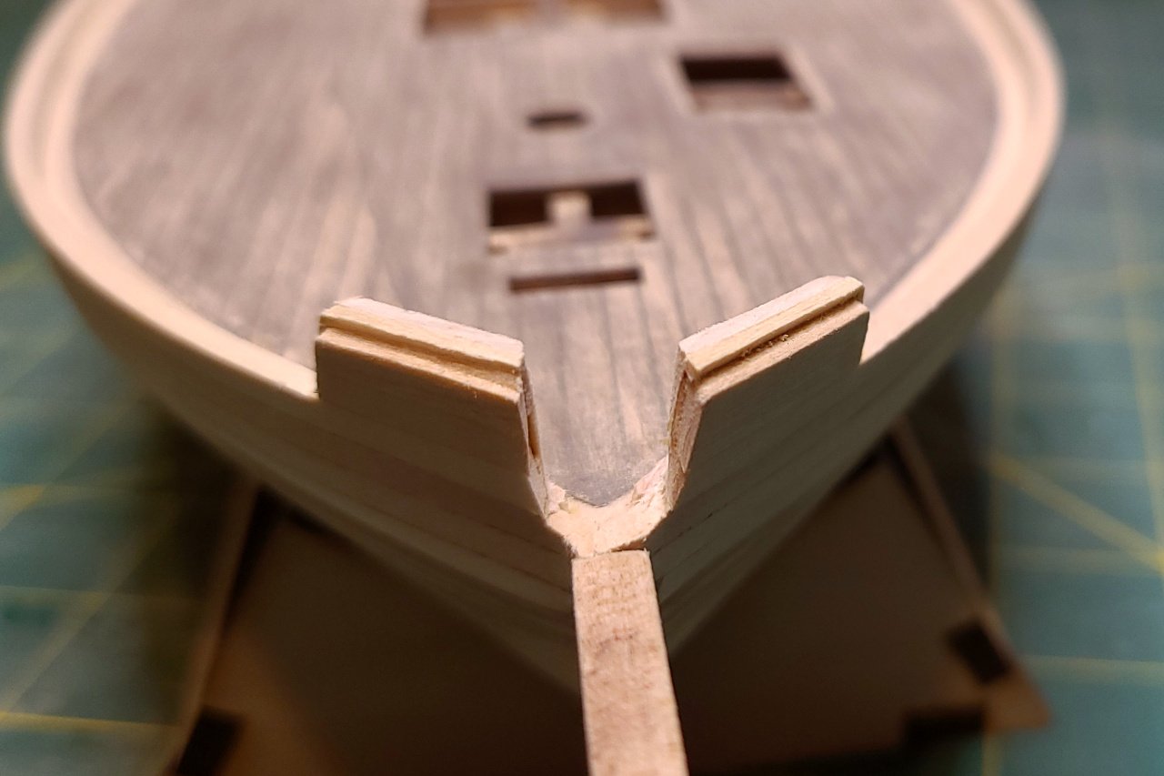
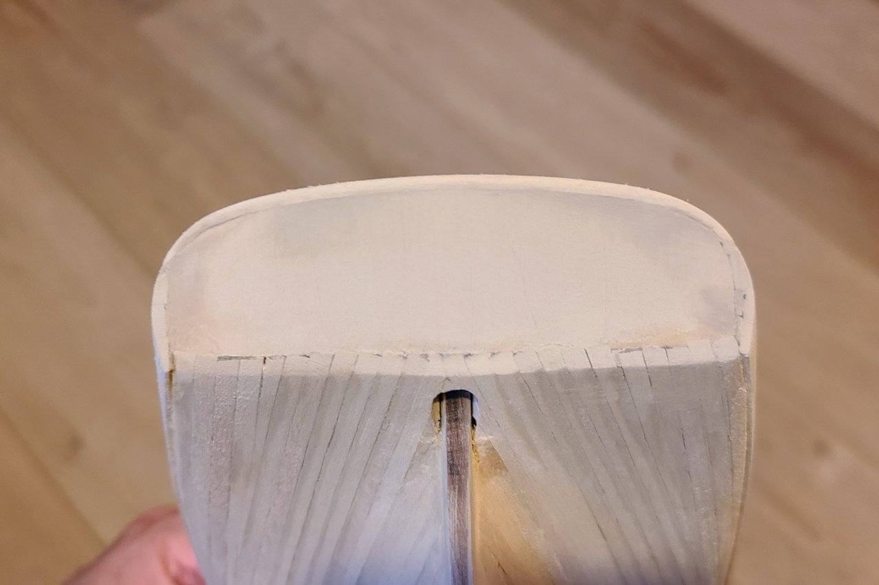
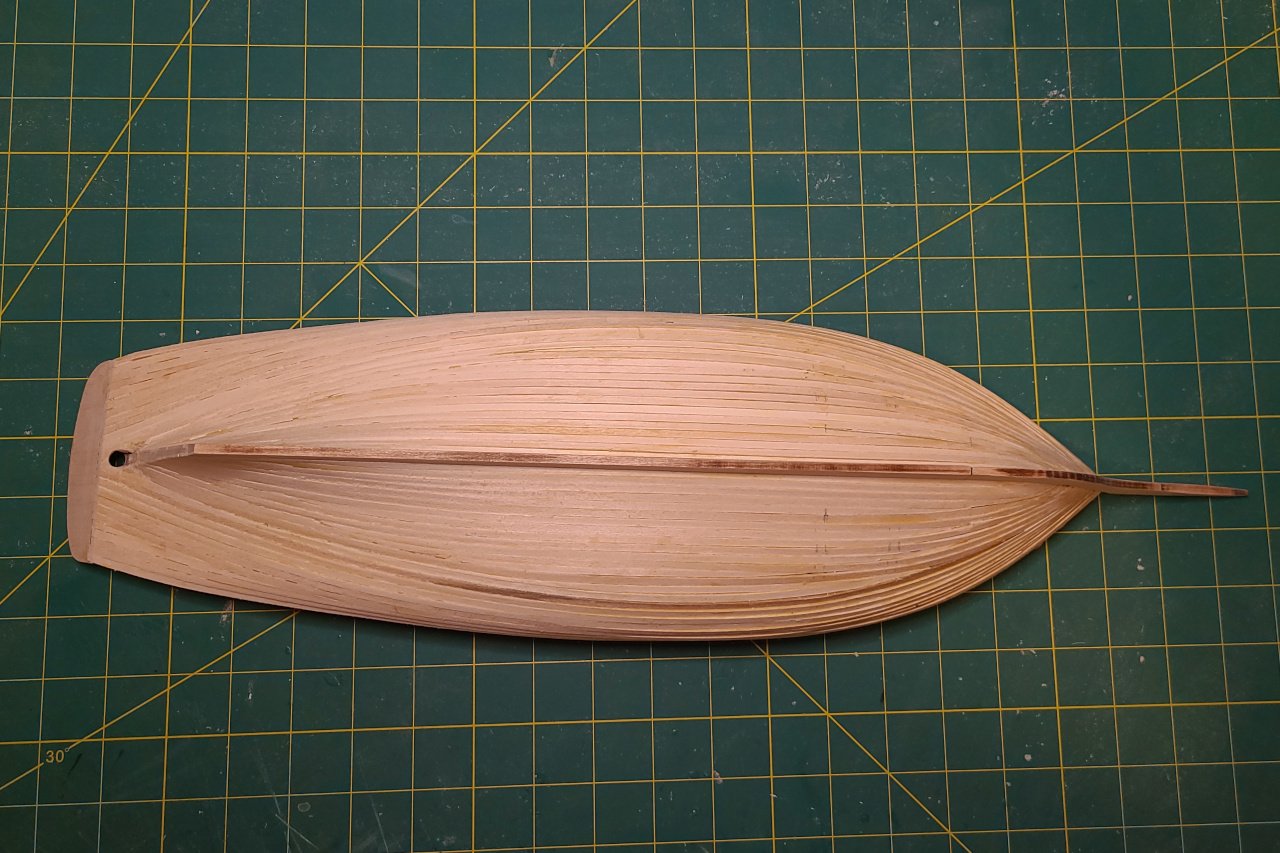
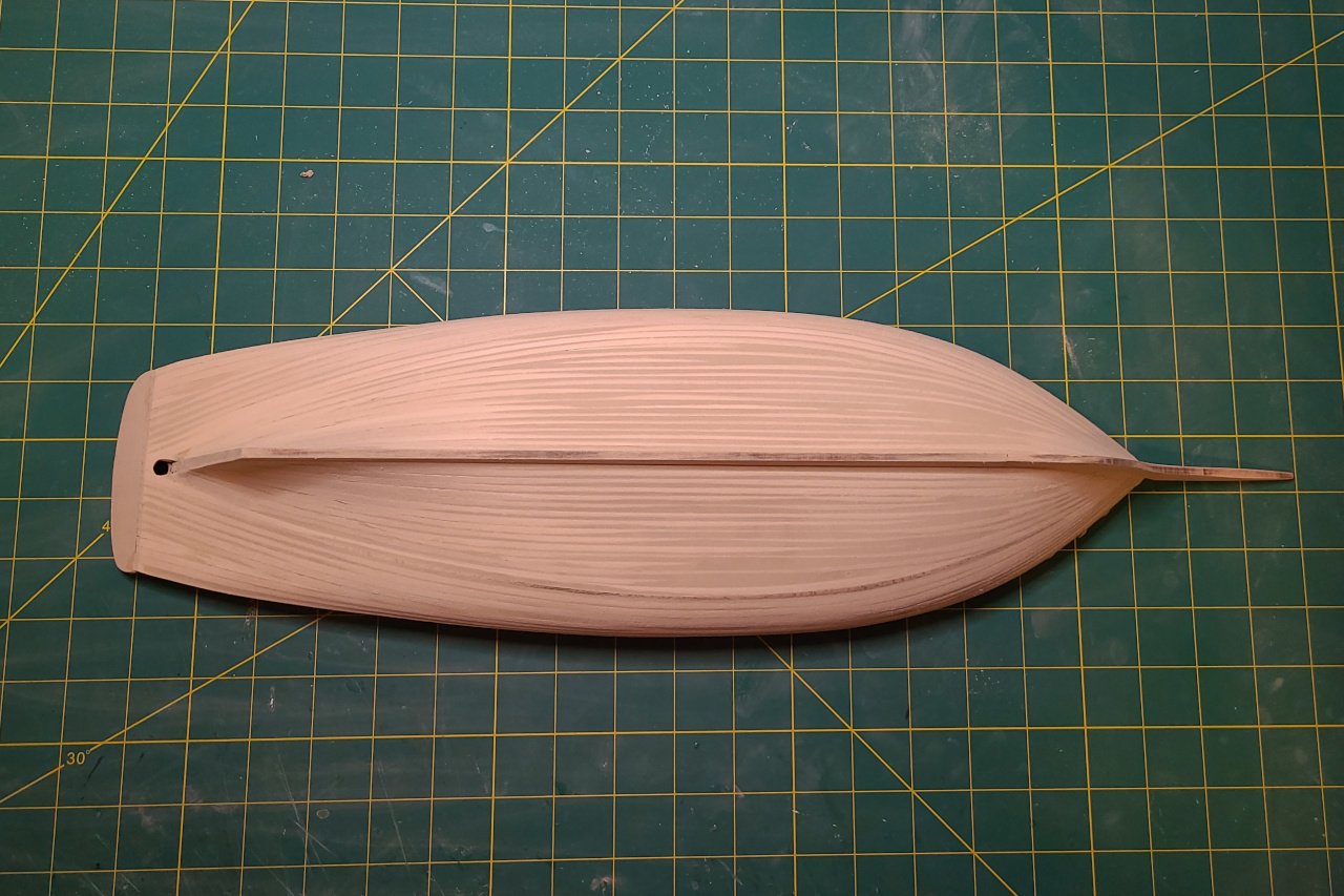
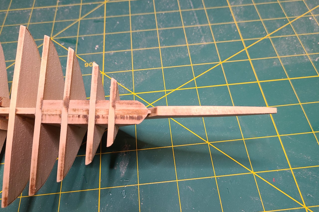
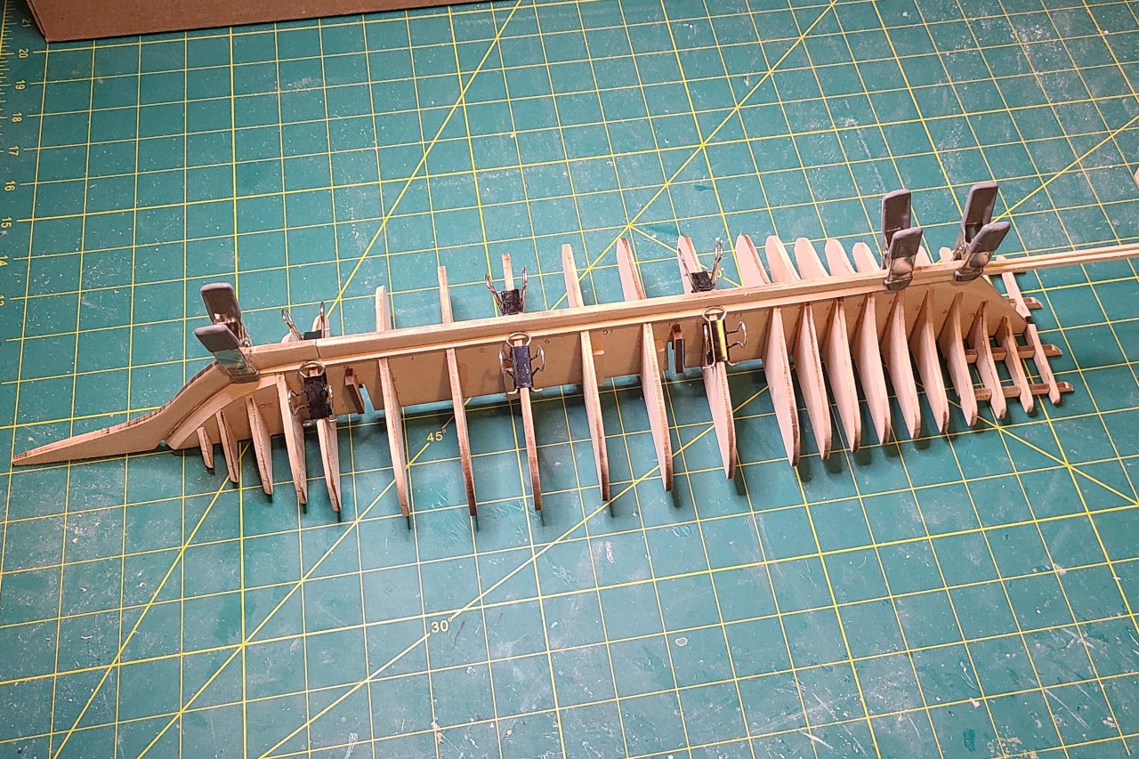
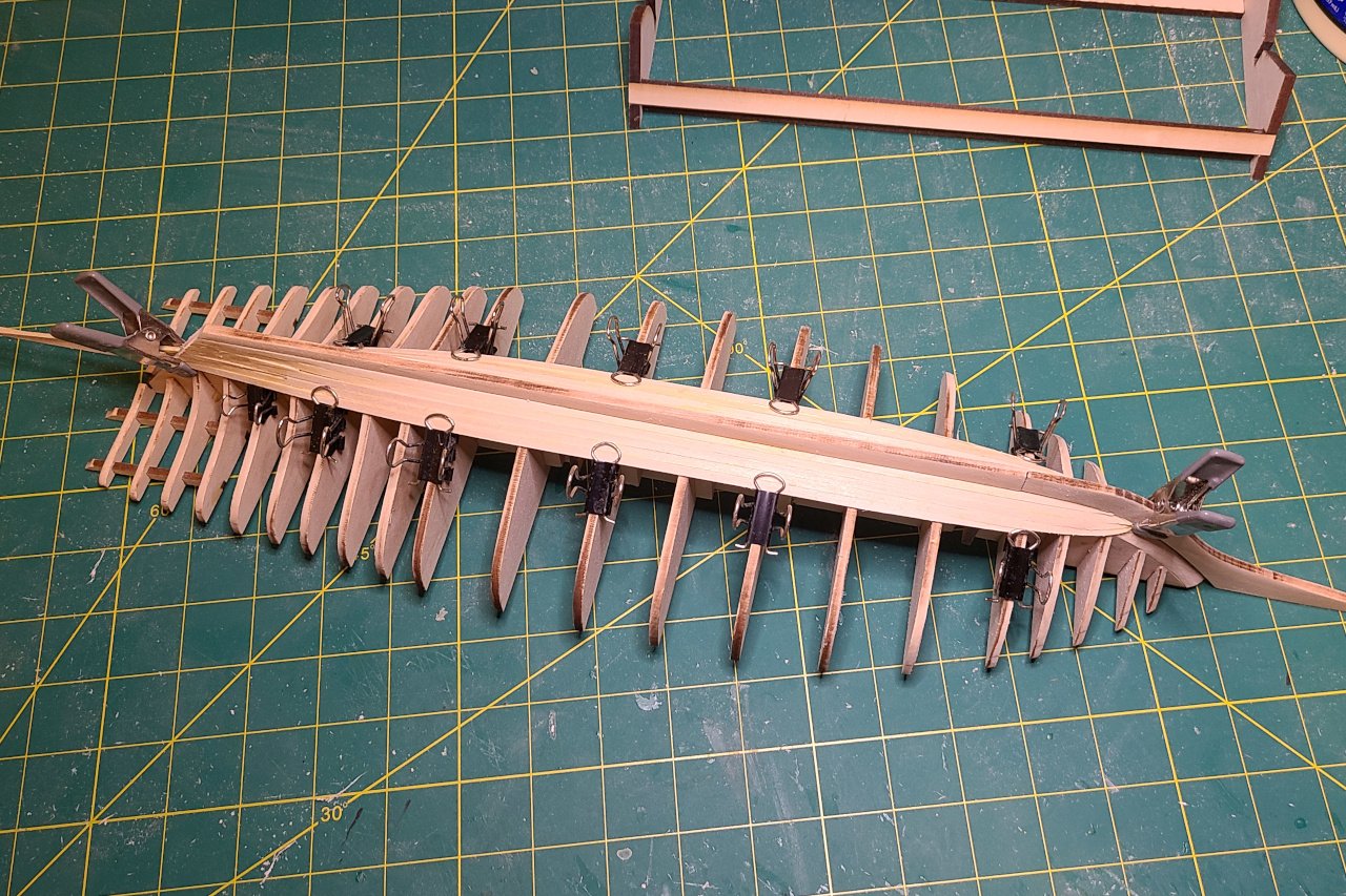
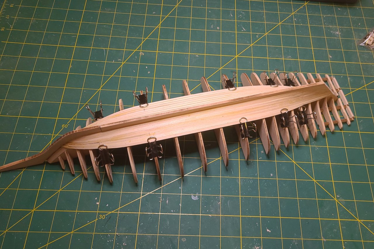
The stem and keel were tapered and then glued on to the thin strip. The ugly gap between keel and stem will need to be filled in later. The gap between the stem / keel and the thin strip on the false keel forms a channel that the planks will fit into. And the first planks are on. More planking... And more planking... It's not too bad, but there are gaps and imperfections. The plank ends at the bow are particularly ugly. Hopefully, filler and sanding will smooth it all out. I added some wood pieces here at the stern. And sanded them down. This will provide more surface area for the stern piece to be glued onto. Note to self: Need to make the stern piece. It needs to be in place before the upper hull can be planked.
-
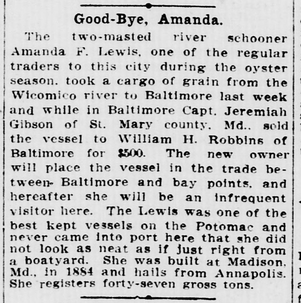
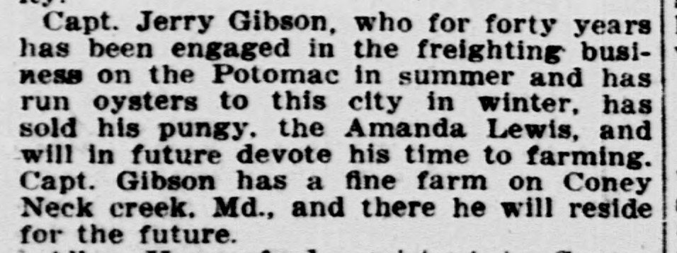
Hi, George. It's great that you have a connection to the Amanda F. Lewis. I presume your relative was Jeremiah Gibson (1846 - 1935)? He was her captain during the early 1900s. Washington Evening Star newspaper 4 August 1908: Washington Evening Star newspaper 28 August 1908:
-
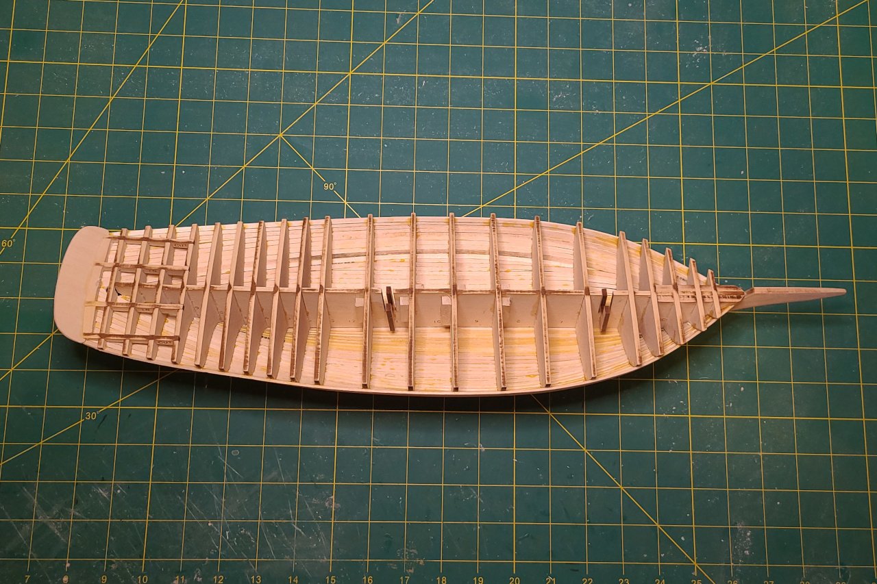
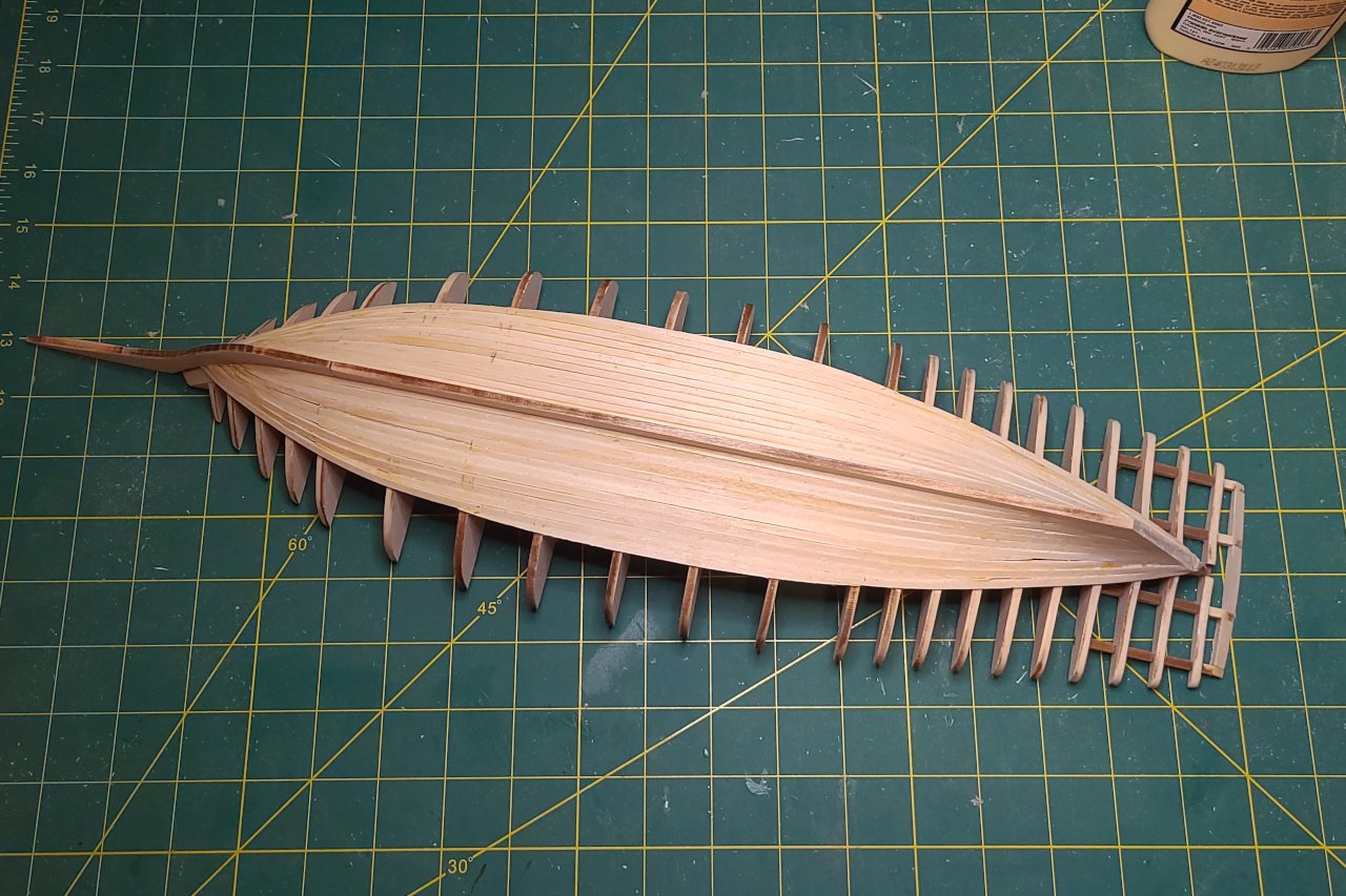
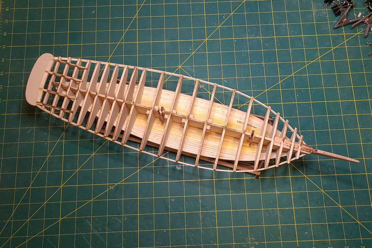
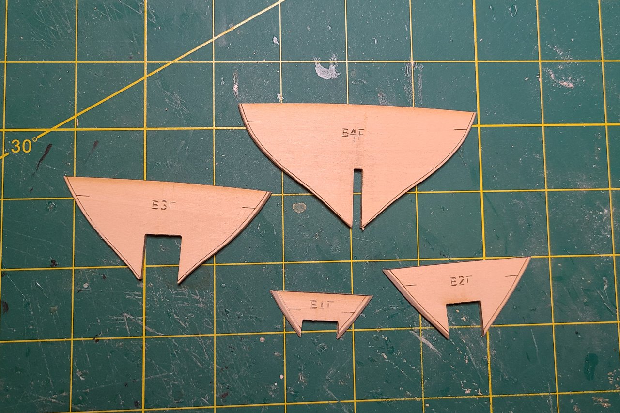
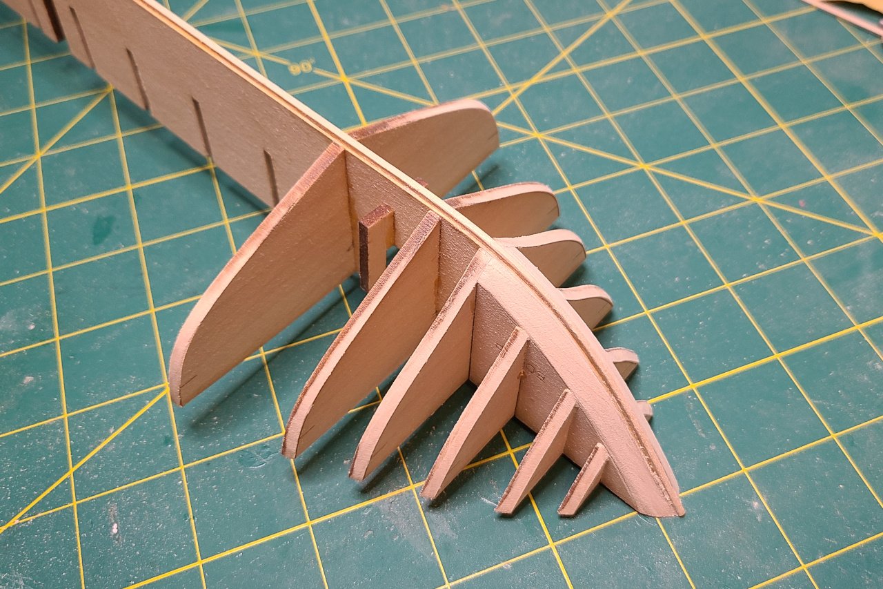
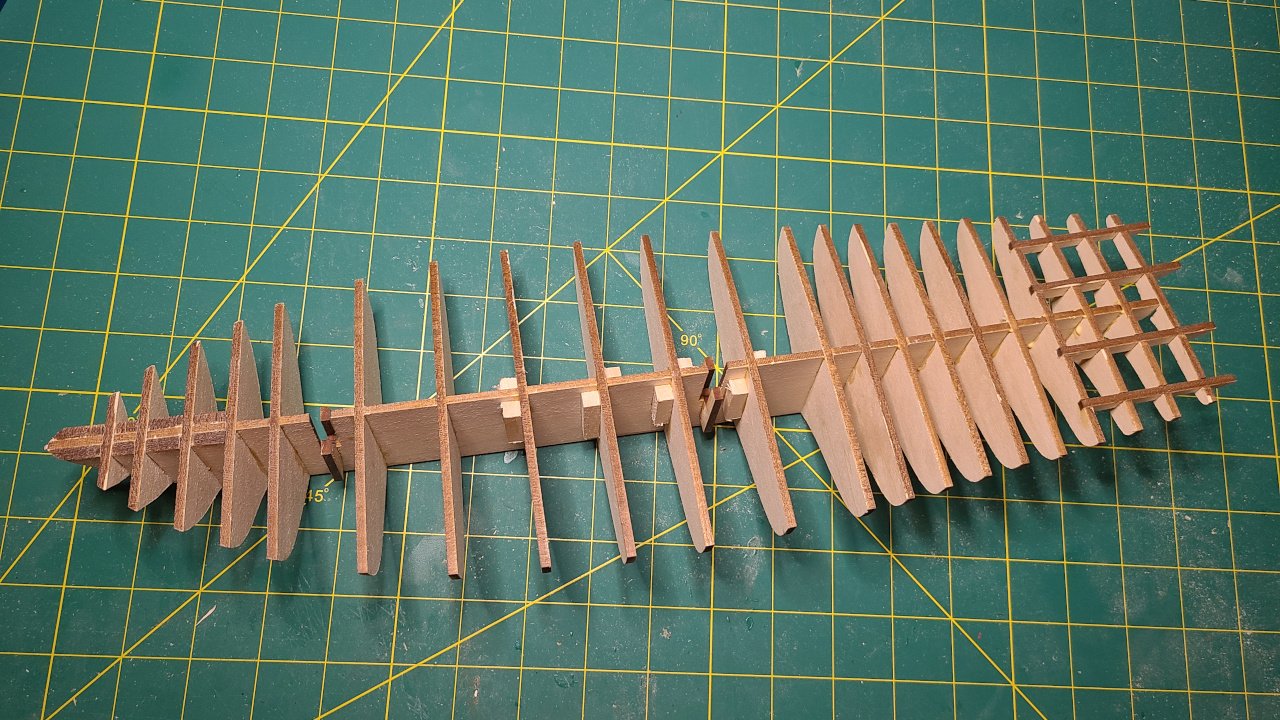
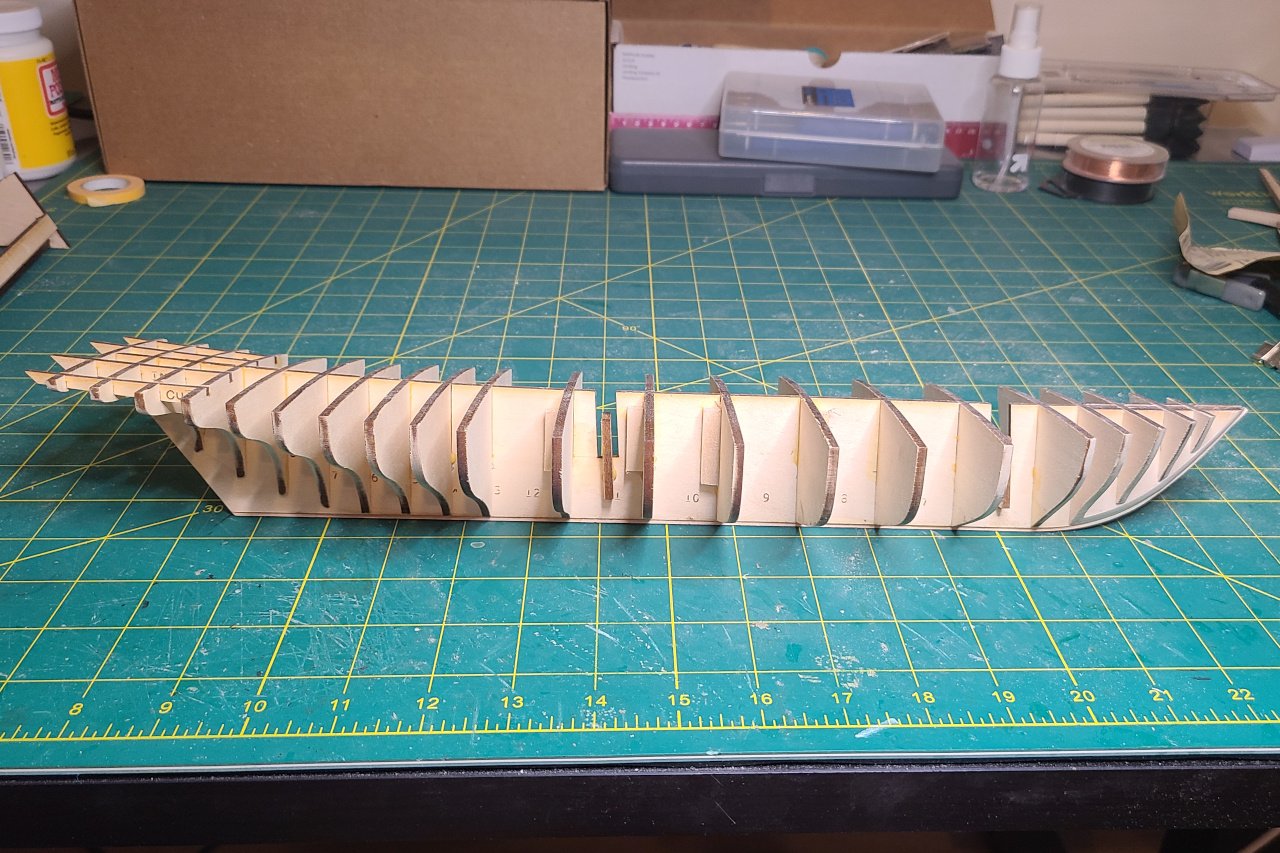
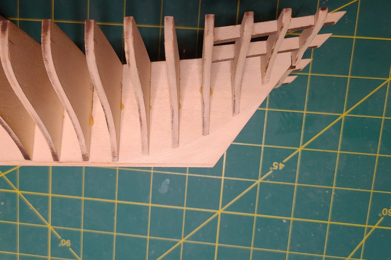
A thin 1/16" x 1/16" strip was glued to the bottom of the false keel to act as the rabbet. Pieces were partially faired using the engraved fairing lines. They will be sanded back further once glued in place. Here are the pieces at the bow after being sanded back. Adding more bulkheads... And more bulkheads... Everything is assembled. Here is the design versus reality: Lots of sanding the bulkheads aft to get a smooth surface. Also, the false keel was sanded thin below the bearding line. And it's just about ready to start planking.
-
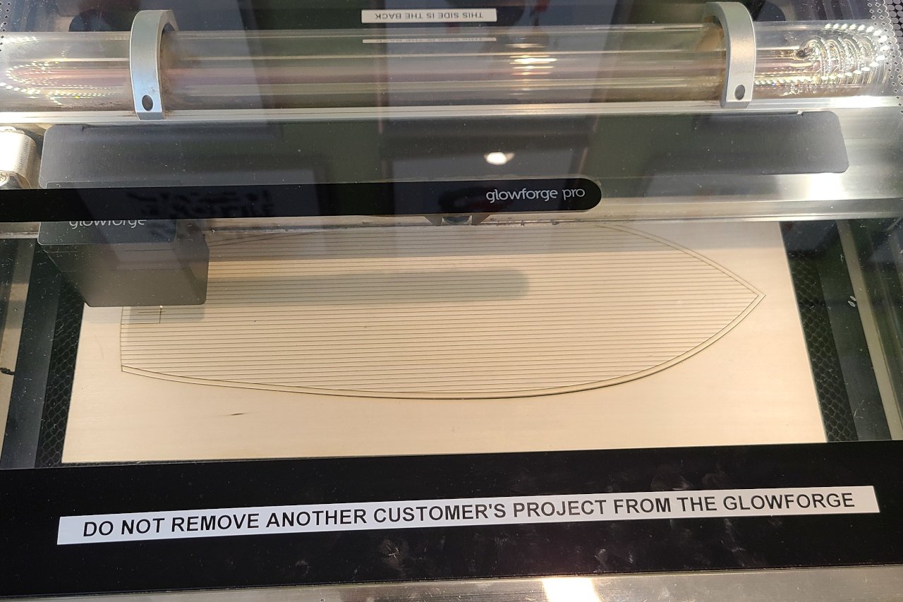
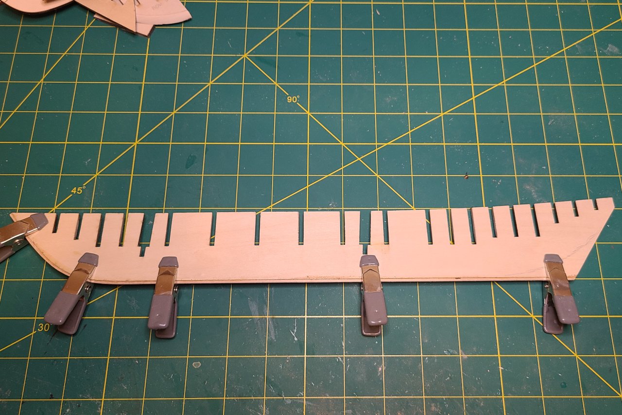
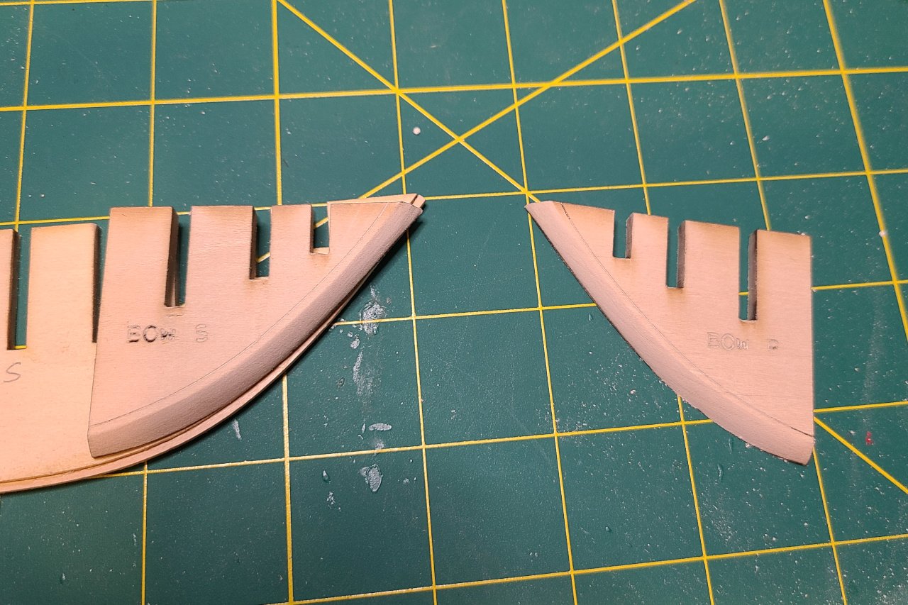
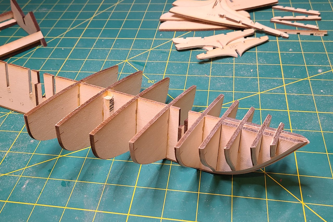
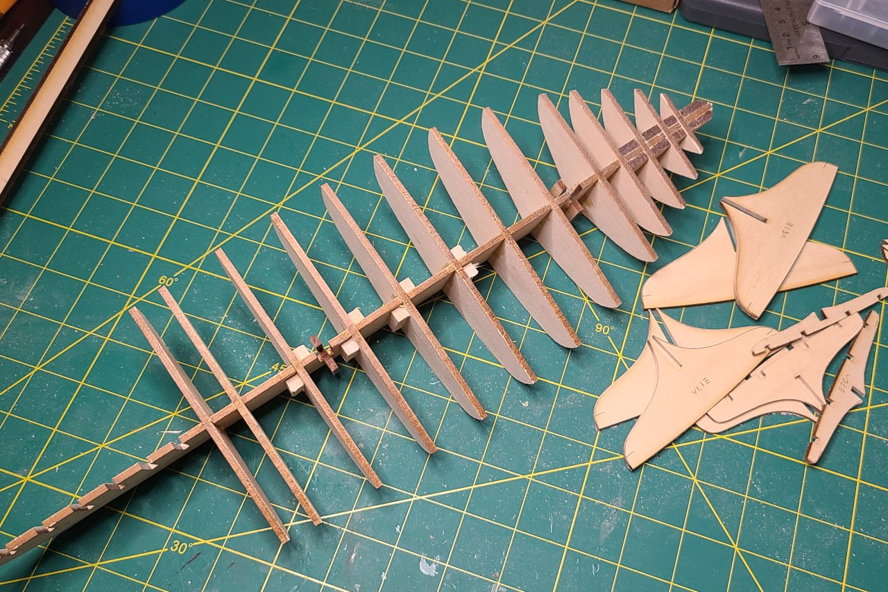
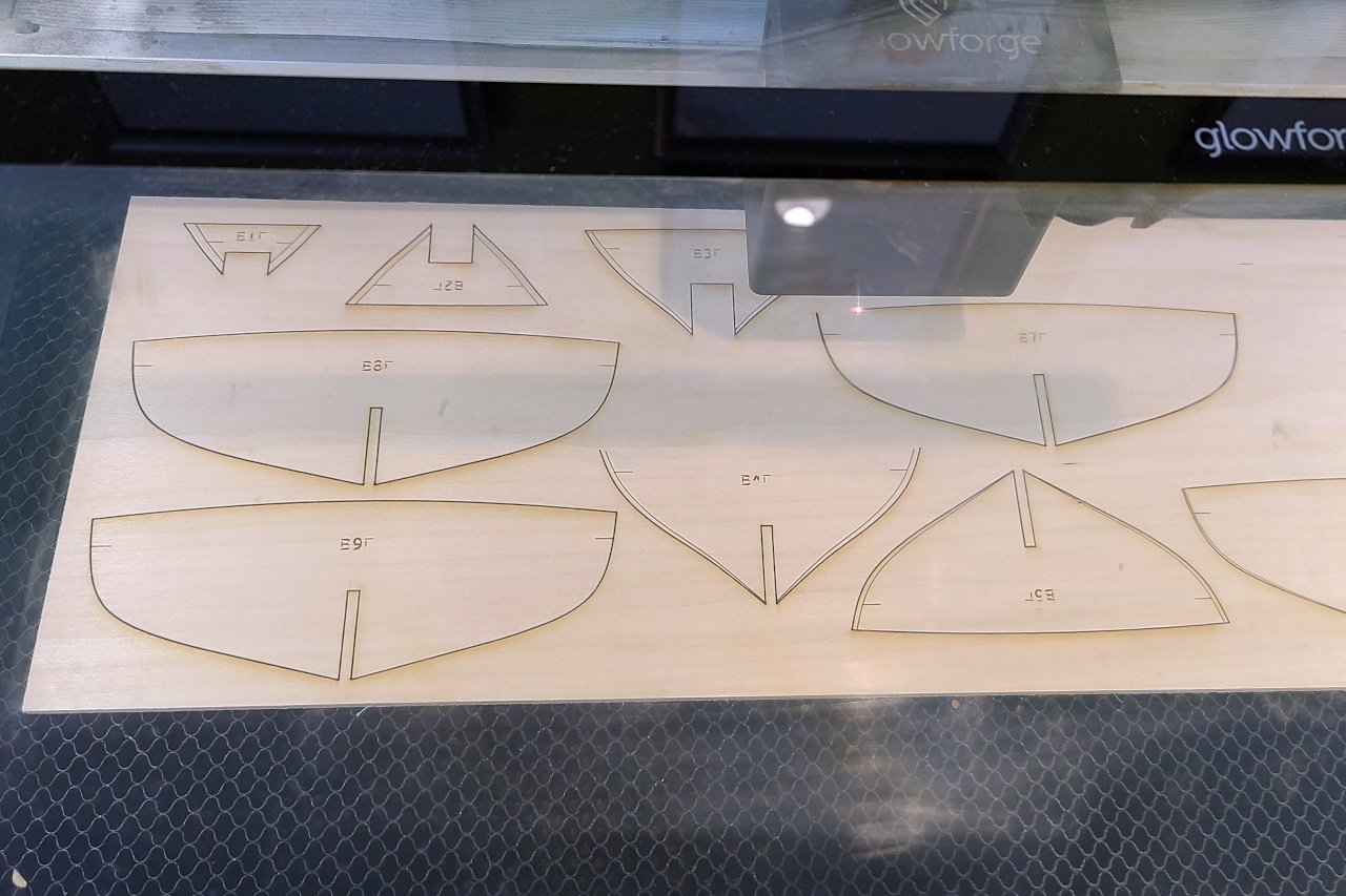
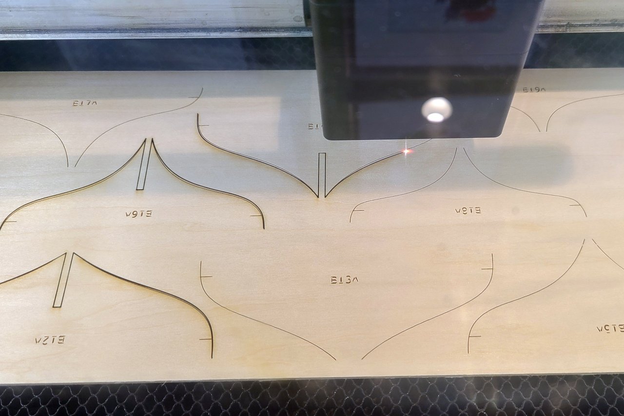
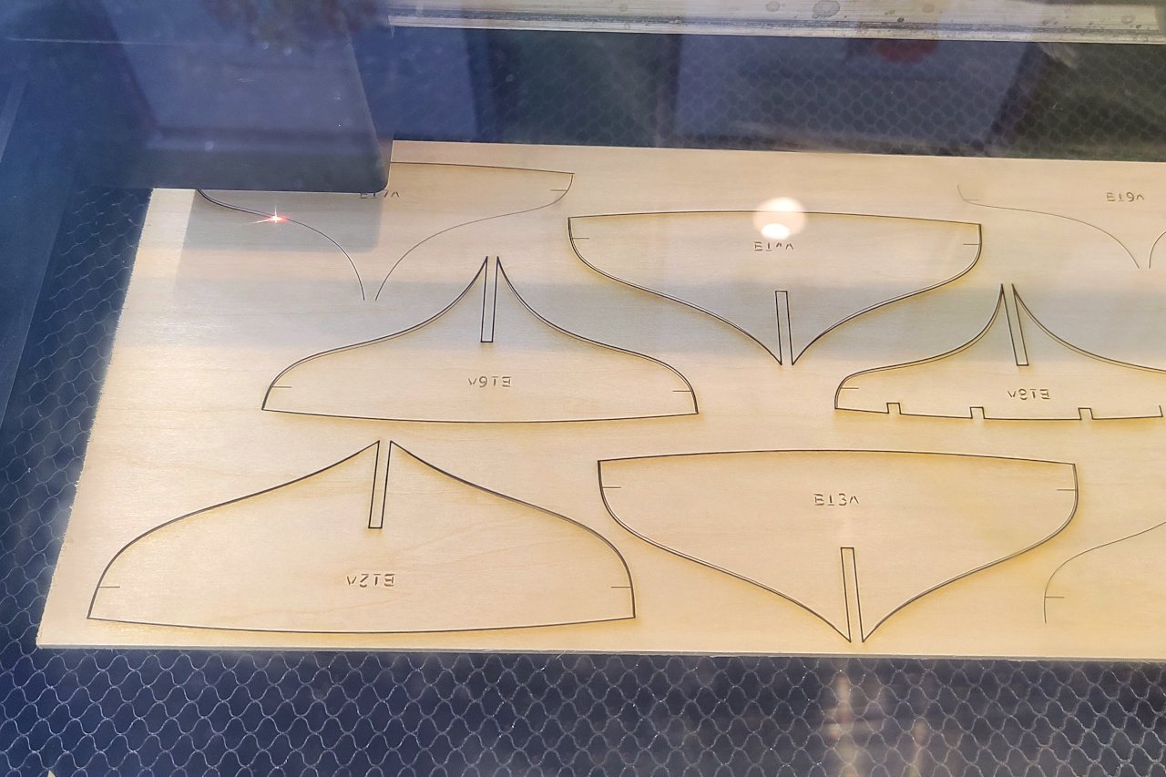
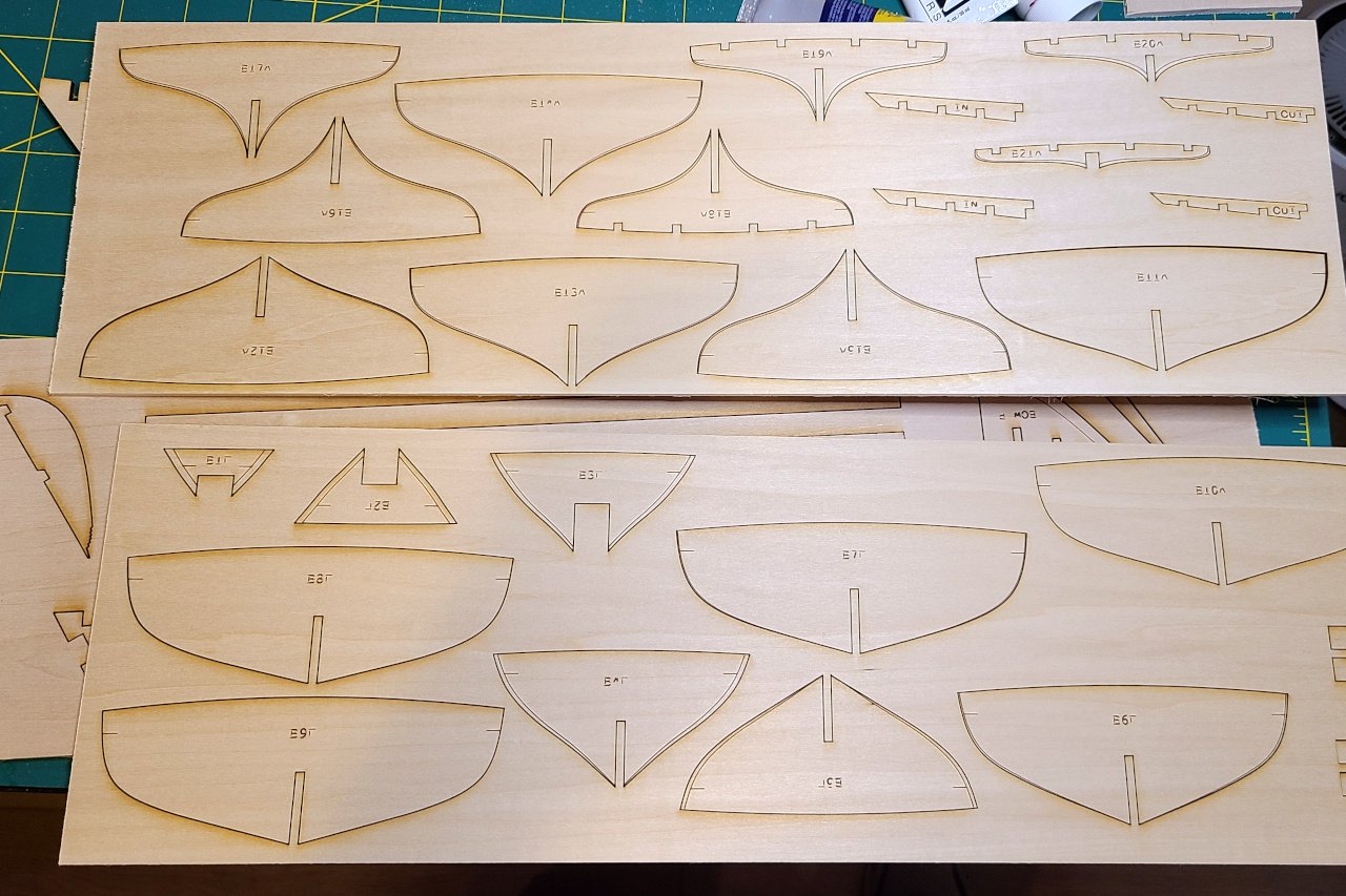
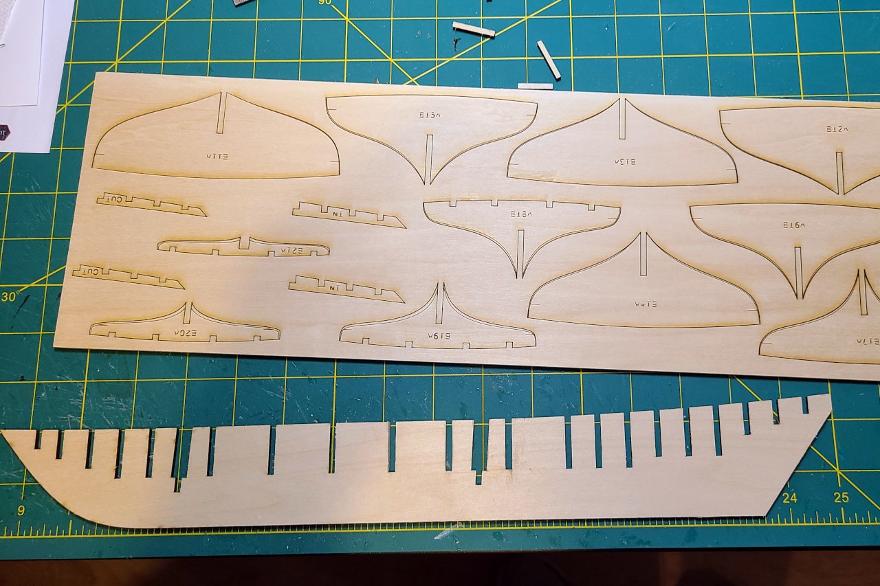
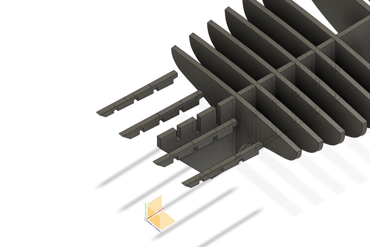
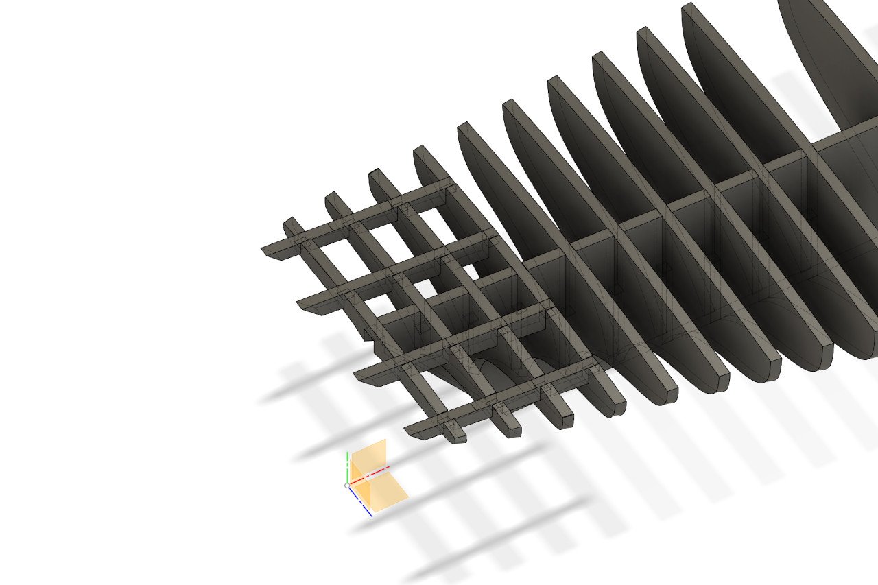
I am very fortunate to have a local library with a Glowforge available for public use. I visited and laser cut my pieces today. VRRRRMMMMM!!!!! ZAPPPPPPPP!!!! BBZZZZZZ!!!! (Insert your favorite laser cutting noises here.) And it's done. Time to put it all together. Some laser cutting notes: During some earlier testing, I estimated a .15mm kerf for the laser. I adjusted my patterns with that in mind, as I didn't want the pieces to be too loose when fitted together. However, I overshot and everything is too tight. I need to sand off a little bit around every notch. Ugh. I had some old laser cutting notes from my Sultana build that said that text should be converted to paths. I did that with all text, but some text has become unreadable. I think the Glowforge can handle text objects in SVG files, so I should have just let them be. Oh well.
-
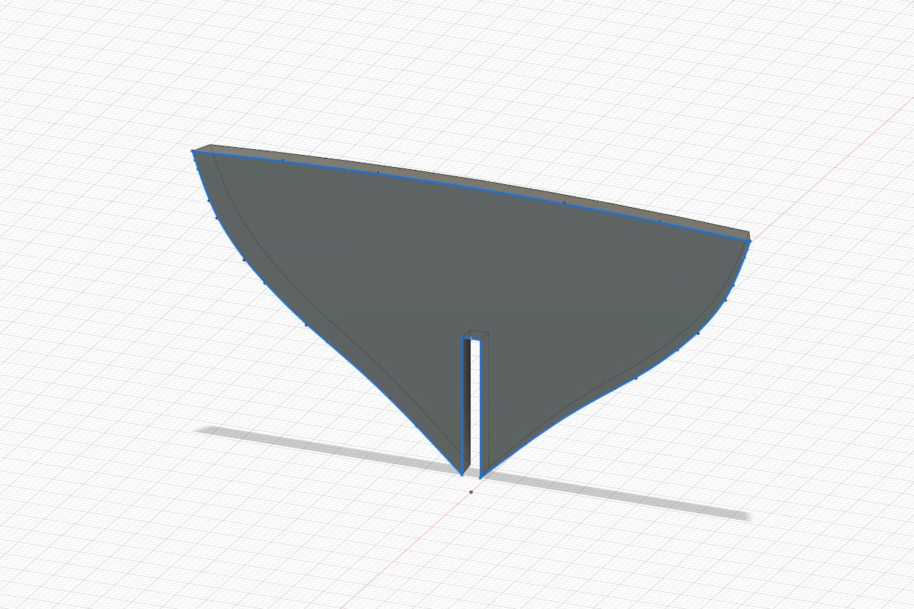
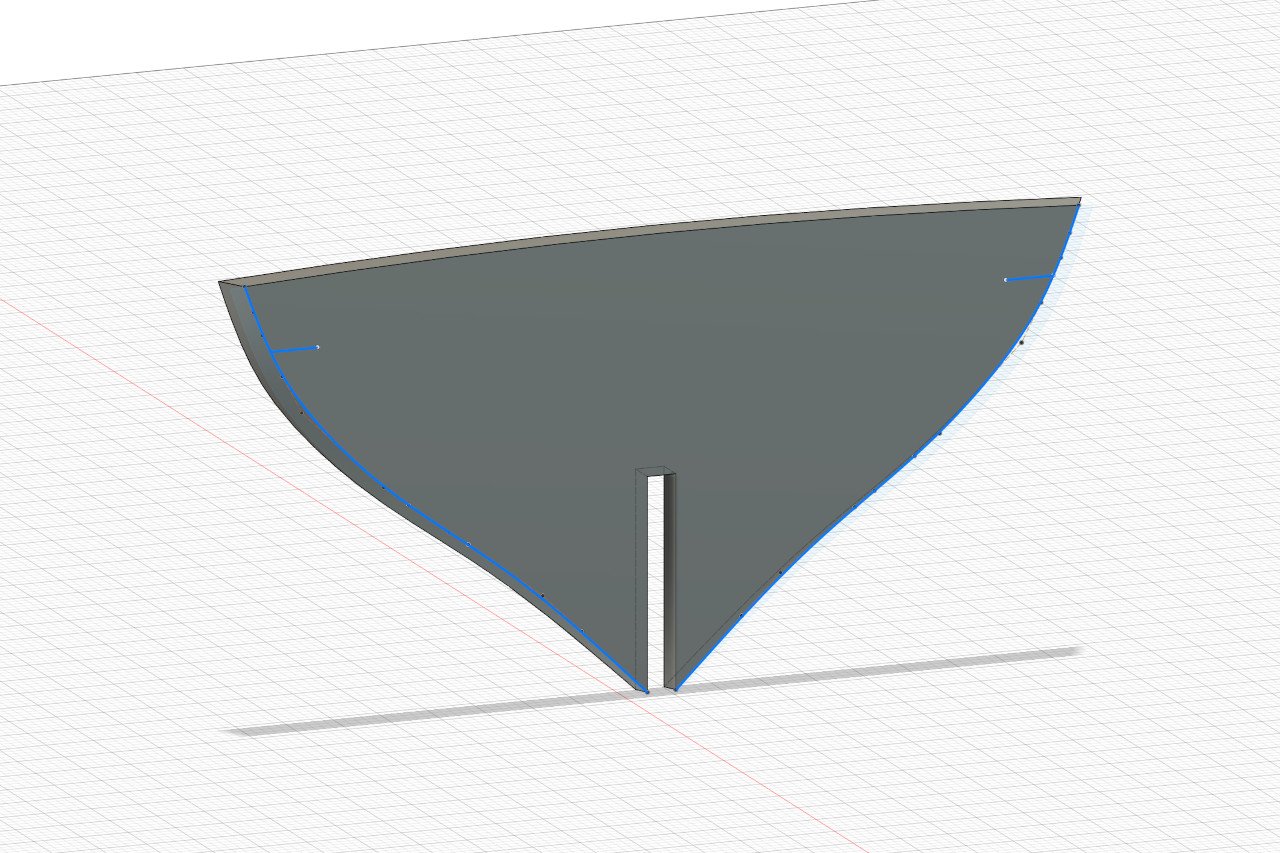
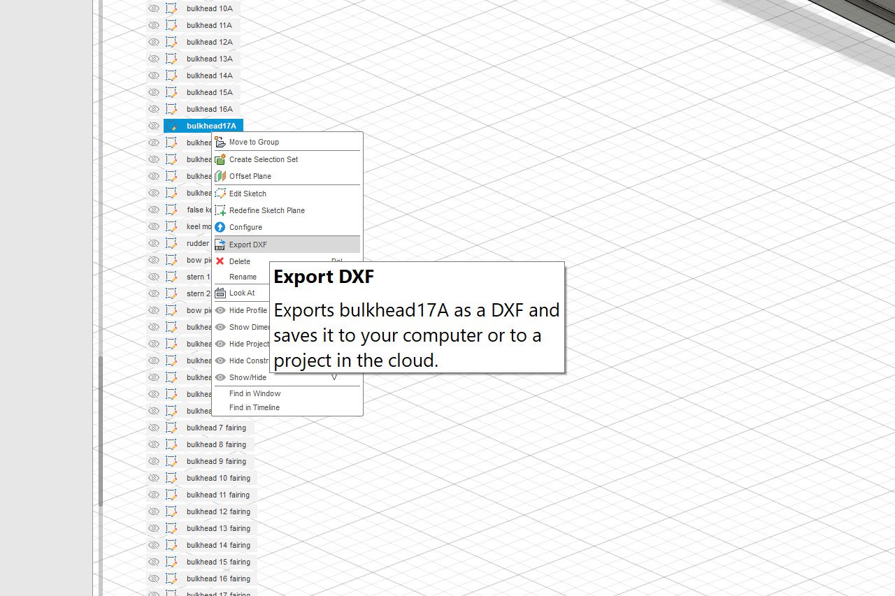
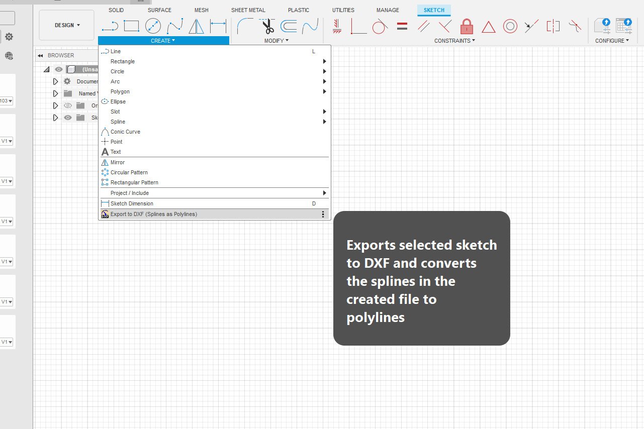
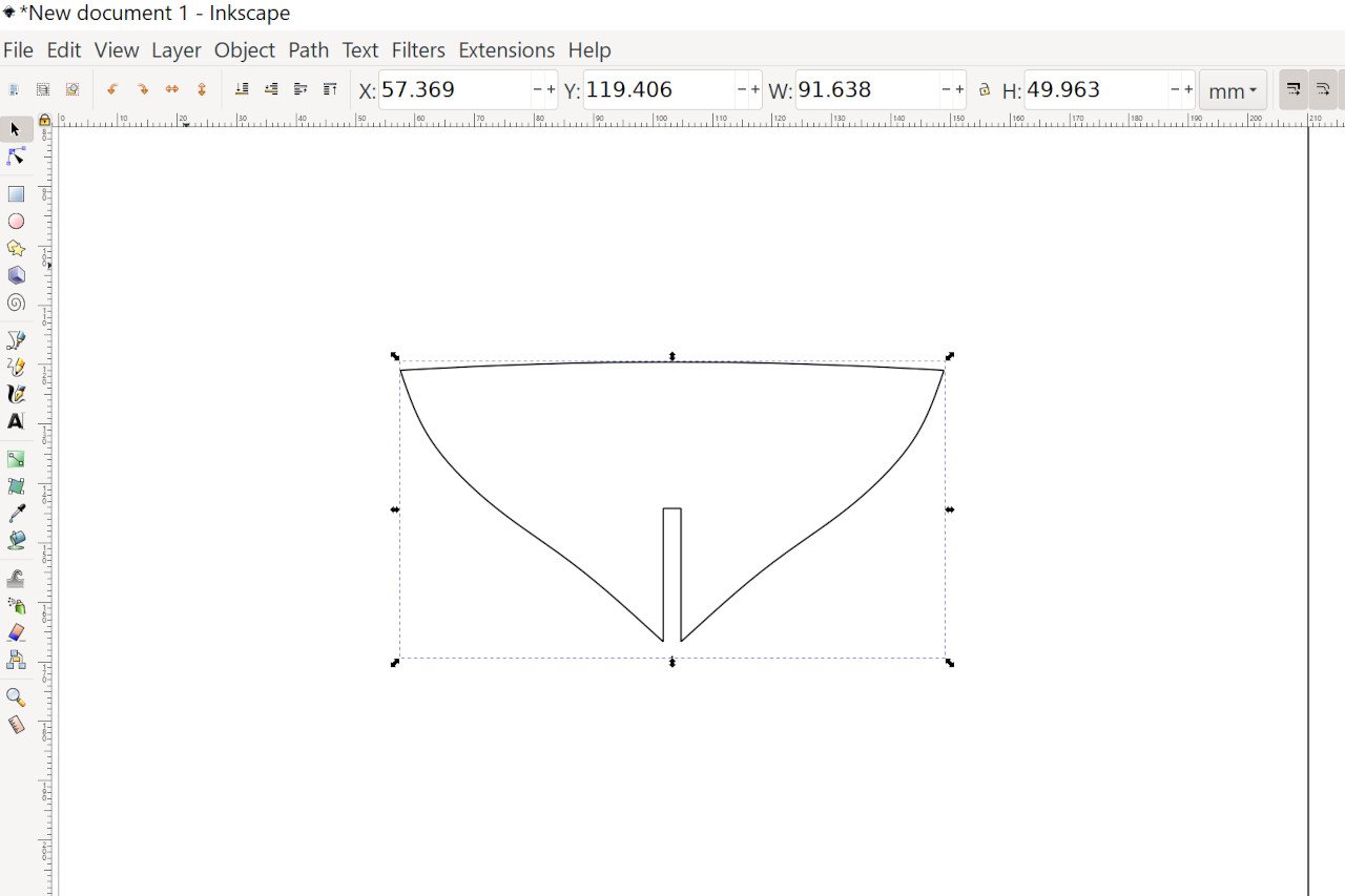
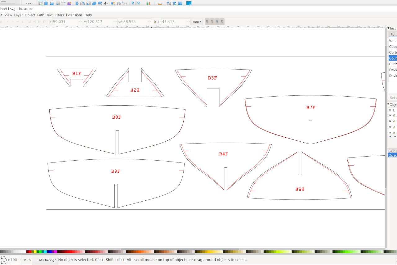
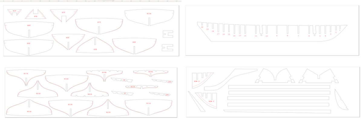
Bulkheads (and other pieces) are composed of two sketches. First is the overall shape (blue lines): And the sketch with the fairing lines or other guidelines: These can be exported to DXF by right clicking on a sketch and choosing the export DXF option. There is one major issue with DXF export and Fusion. If the sketch contains fit-point splines, those splines don't get exported. (Control-point splines are ok.) The solution is to download and install the DXF Spline To Polyline plugin for Fusion. Once installed, when you are editing a sketch, there is a new option under the Create menu to export with splines converted to polylines. However, when I tried this, I still had issues with the converted splines not appearing after importing the DXF into Inkscape. The solution I found was to open the DXF in QCAD, then immediately Save As a new DXF file. The file output by QCAD was finally usable. I laid out my pieces for laser cutting in Inkscape. I created a new Inkscape document with dimensions equal to the material. Then import each DXF. For fairing lines, the paths are changed to red. These will be engraved rather than cut. Add each piece one by one, and add some text to identify the pieces. Four sheets in total were required. Next time: laser cutting.

-
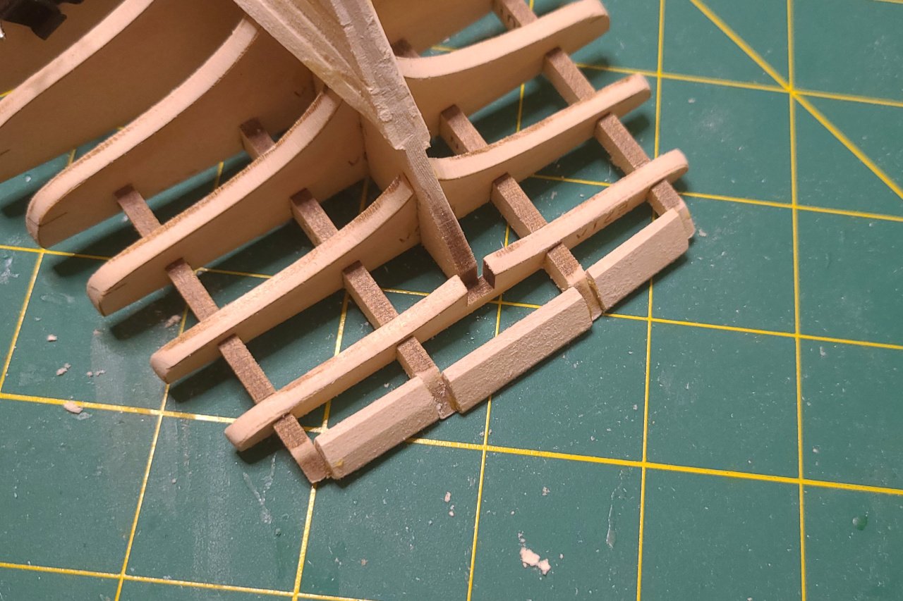
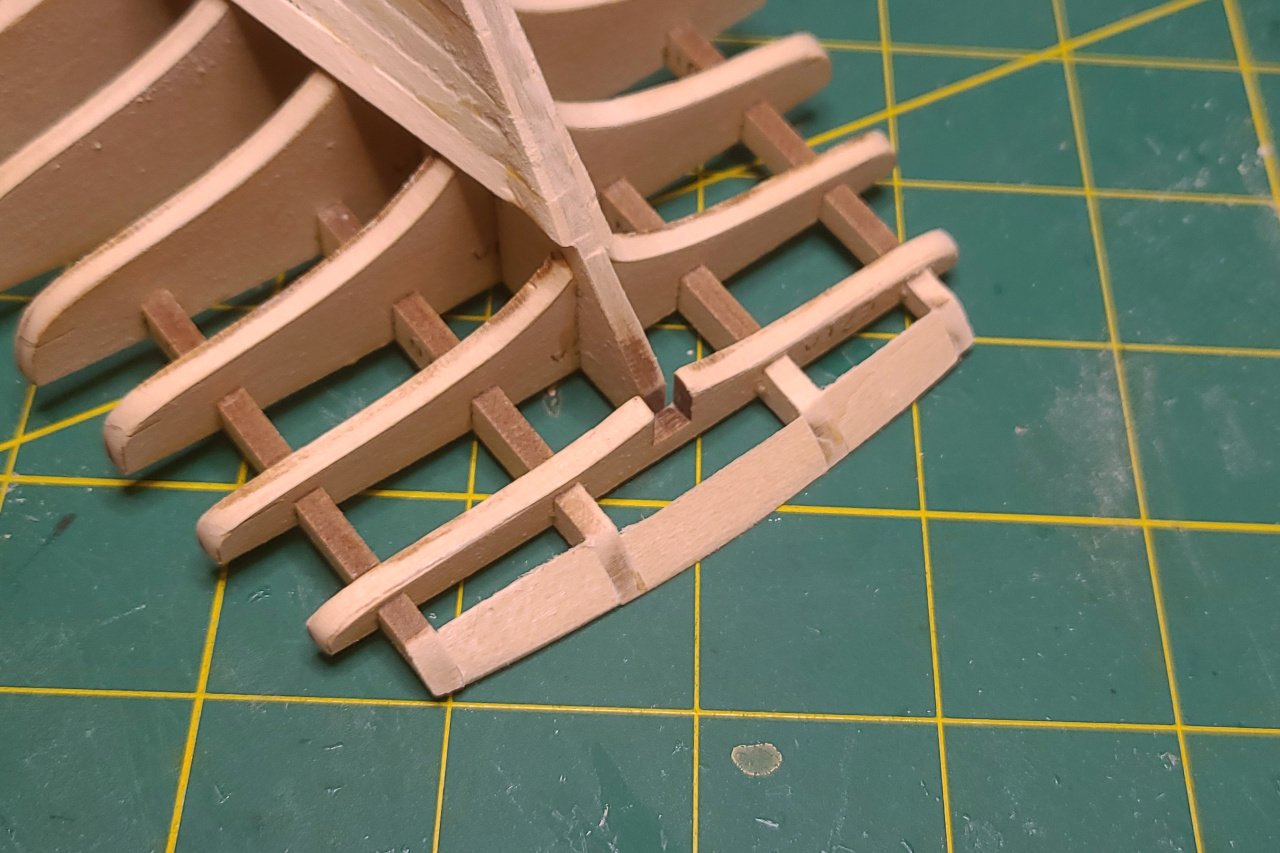
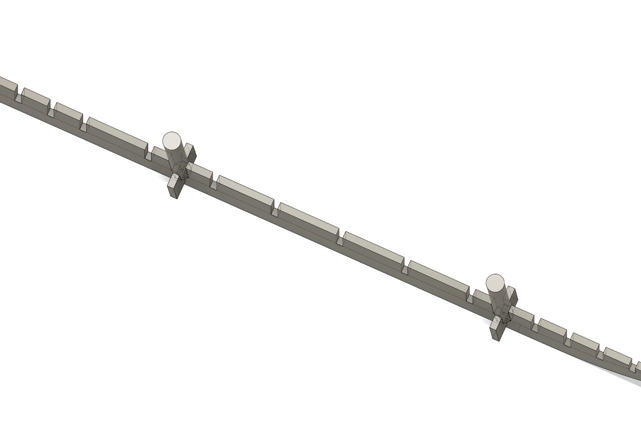
Sorting out the notches to make the stern pieces hold together: Added some pieces to hold the masts: The stem, keel, and sternpost were separated into different pieces and the rudder shape was defined. I'm happy with how things are at this point. Now I need to export each of the shapes, create a layout for each laser cut sheet, and get it all laser cut.
-
Hi, Deltawaldo. Welcome to Model Ship World. The hull shape I've been using for this project isn't an enclosed mesh, so it's not suitable for 3D printing. I would have to start over with the goal of making a 3D printable object. If you're truly interested, I can give it a go. I'm very excited to hear that you're related to shipwright Joseph W. Brooks (1832 - 1915). Do you have any family history to share? Pungies built by J. W. Brooks (presumed incomplete): A. Weiskittle - 1882 Amanda F. Lewis - 1884 Angie McNamara - 1862 Christopher C. Fallin - 1869 Francis J. Ruth - 1871 G. A. Kirwan - 1882 Hattie and Francis - 1881 J. W. Brooks - 1868 Moore and Brady - 1880 Twilight - 1884 In a Baltimore Sun article from March 6th, 1938, author Eric Steinlein calls Twilight a sister ship of the Amanda F. Lewis. Geoffrey Footner, in Tidewater Triumph, says that Brooks' last pungy was built in 1885, but does not name it.
-
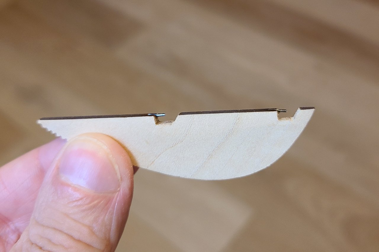
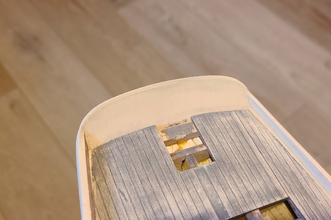
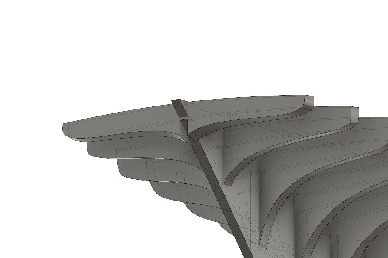
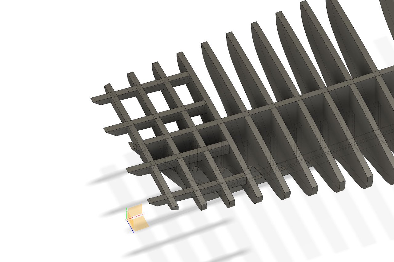
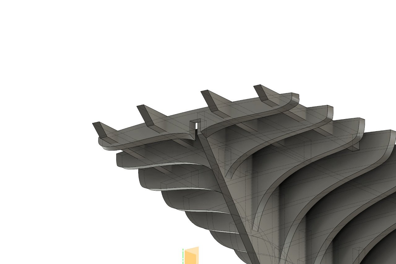
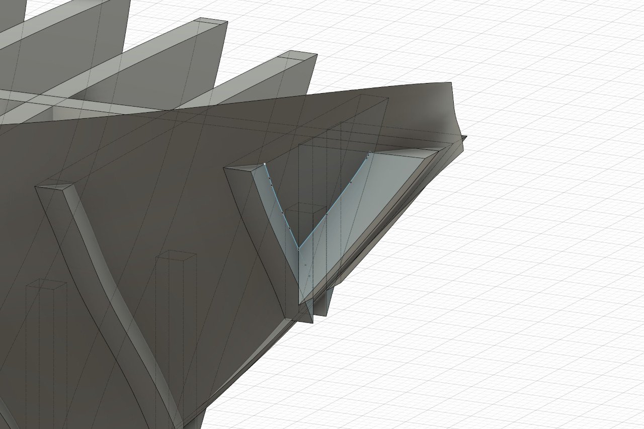
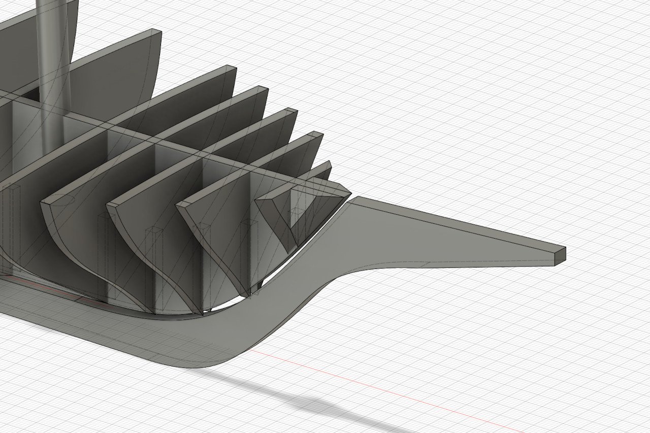
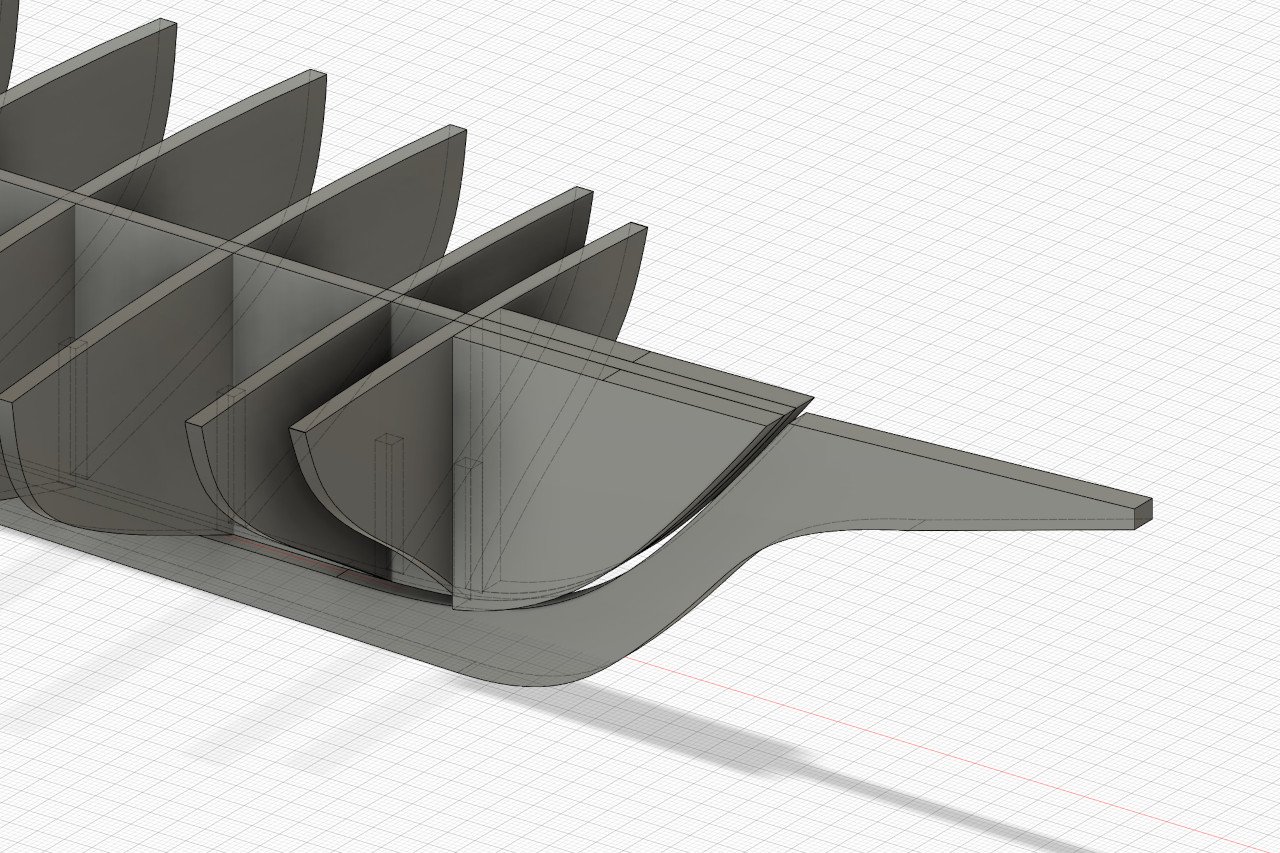
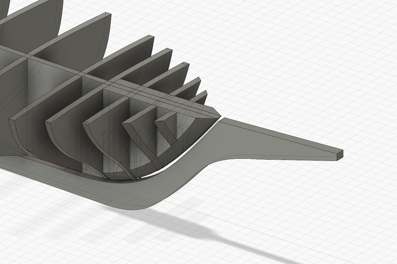
Let's look at the stern. The aft-most bulkhead has a problem. The notch I originally planned isn't correctly sized, and any notch I do make will leave little to no room for the pieces to join. However, I wanted to add some pieces anyway that would define the end of the transom and provide a surface for the stern piece to attach. They can also strengthen the whole aft structure. And they provide a solution to the issue above, because the final bulkhead can be attached to them. The aft-most bulkhead still needs a notch so that there is room for the stern post to rise behind it. (The stern post appears in the picture above, but not the one below.) Next I worked on determining the fairing guidelines of each bulkhead. This was done by finding the intersection of the hull surface with the forward or aft edge of the bulkhead. An example of the final design of a bulkhead piece is below. Note the short horizontal lines on each side. Those were added to mark the lie of the wale on each piece. Using the fairing lines, I created faired versions of each bulkhead piece within Fusion. The animation below shows the difference between the pieces before and after fairing. Let's check by todo list. Some items are complete, and some have been added. Add some shapes at the bow to help define its shape. Add pieces to form the transom and stern. Inscribe fairing lines on each bulkhead piece. Inscribe lines on the bulkheads to indicate the line of the wale. Add pieces to hold the masts in place. Finalize the shape of the false keel, add the rabbet, etc. Add the remaining notches so that the whole thing fits together like a puzzle. Save designs and create laser cutting layout. Take it to be laser cut.
-
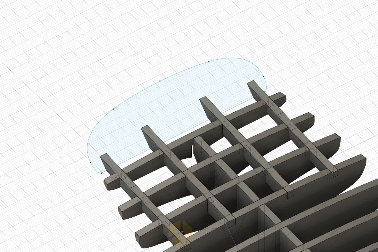
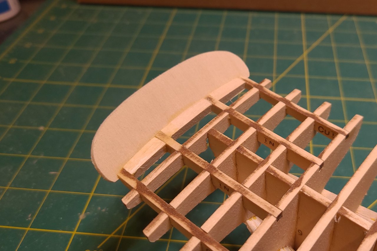
I'm working on refining the 3D design. I now have what lots of kits call a "false keel" - the internal piece that the bulkheads are glued to. And I traced out mock-ups of the stem, keel, sternpost, and rudder, though those aren't in their final form. Note the thin gap between keel and body. When I build this, I will place a thin 1/16" x 1/16" strip in that gap to act as the rabbet. I'd like some extra surface at the bow on which to start the planking. Using the design at this point, I could place two pieces at the bow as shown. I'd like to see how that will work once the bulkheads are faired. I can visualize that by first finding the intersection of the bulkheads with the hull inner surface. And using those intersection lines, I can trim the bulkhead pieces so they appear as they will be once faired. Here, the first bulkhead and the two new pieces are faired. First, it seems like there isn't much point in having the first bulkhead so far forward. Also, the new pieces are so small that they only help for the uppermost hull planks. Instead, I thought to add much larger pieces at the bow, as shown below. This shows the design with the new pieces as well as the first two bulkheads faired. The forward-most bulkhead has been moved aft slightly. I think the surfaces now will make things easy to handle all the hull planks at the bow. I still need to cut out new notches in the pieces to accommodate the new form.
-
Topsail schooner sail plans and rigging
SardonicMeow replied to Dr PR's topic in Masting, rigging and sails
Phil, I found a picture of the mystery sail on the Lynx. Have a look at https://schoonerwoodwind.com/star-spangled-sailabration/ and scroll about halfway down. You'll see that Lynx has a two-part fore course. I have no idea if this arrangement would have existed historically. Photo credit: Ken Kaye
- 104 replies
-
- 2
-

-

-
- schooner rigging
- Topsail schooner
- (and 1 more)
-
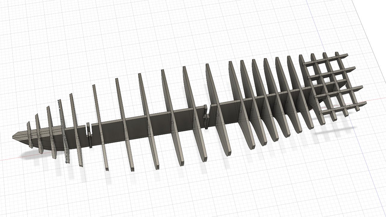
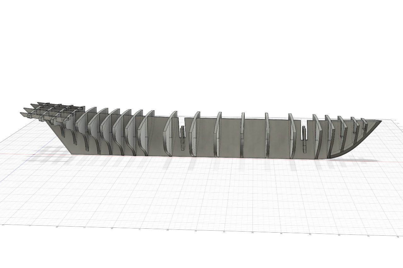
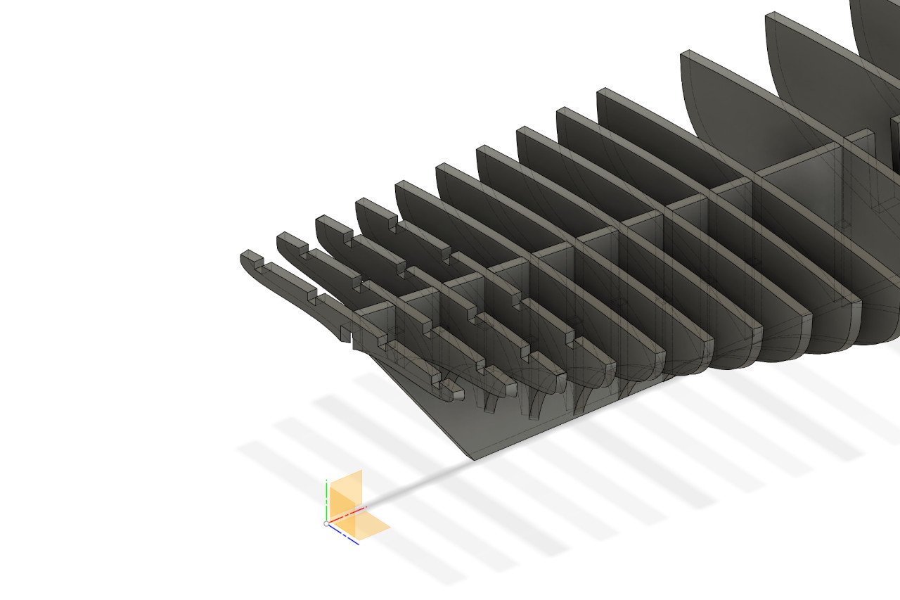
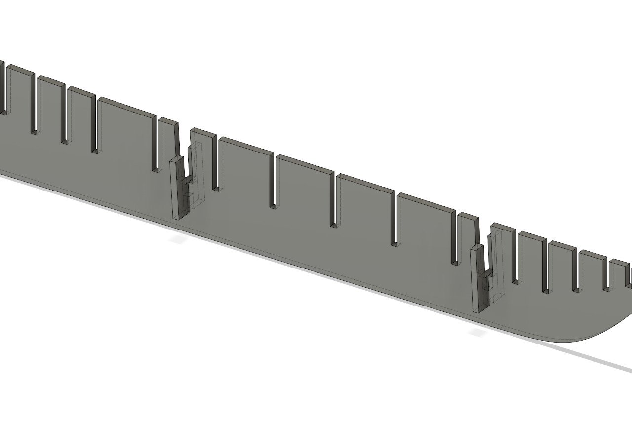
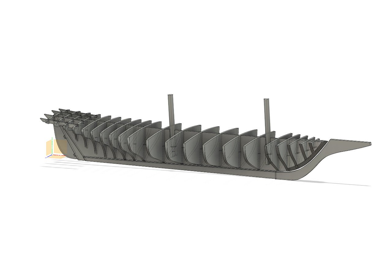
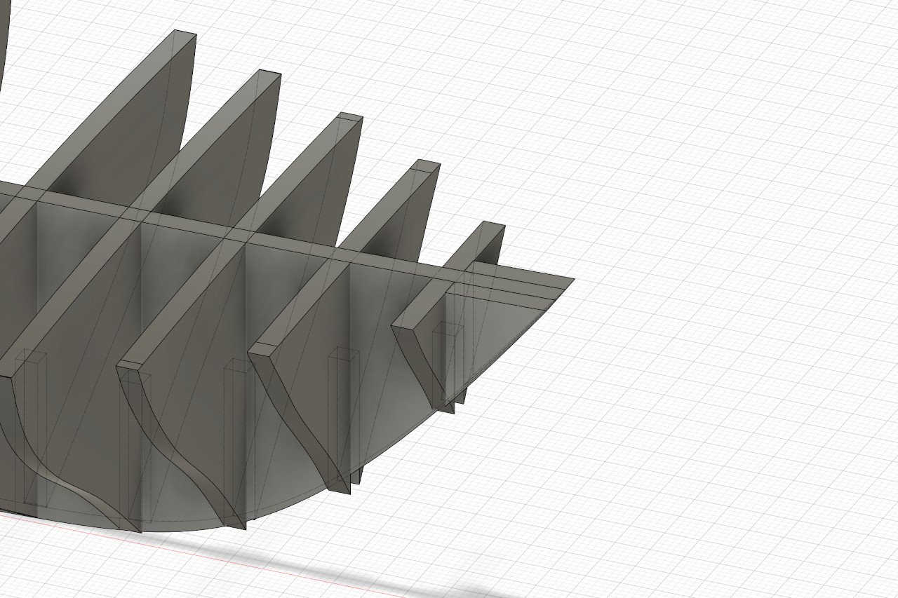
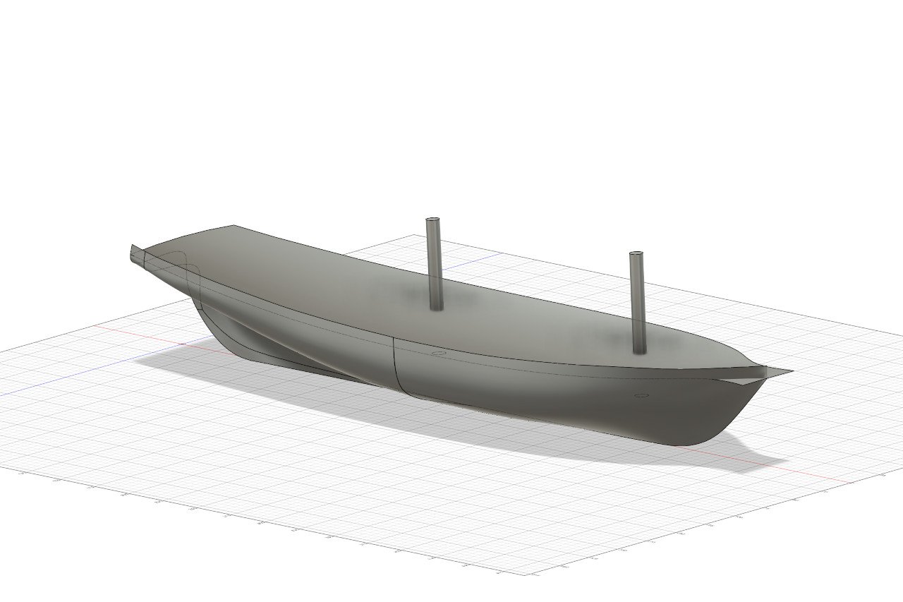
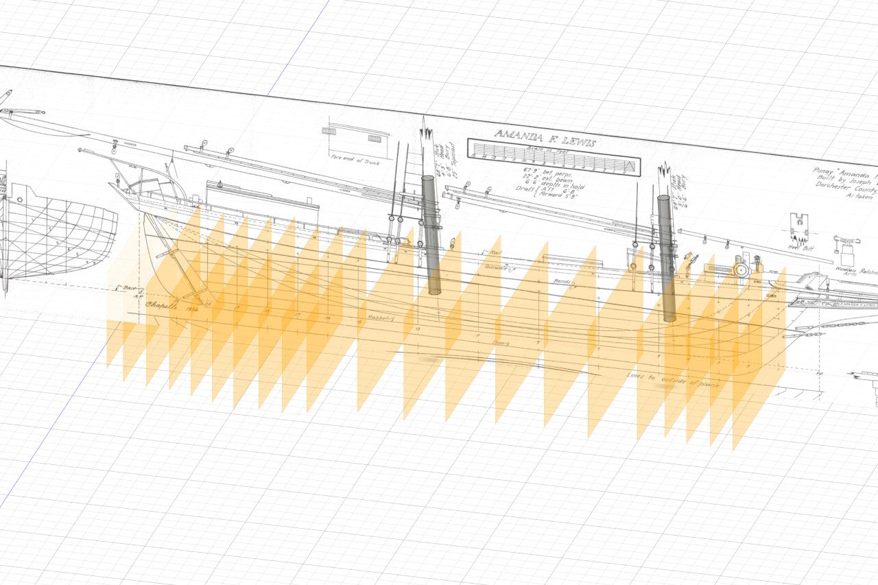
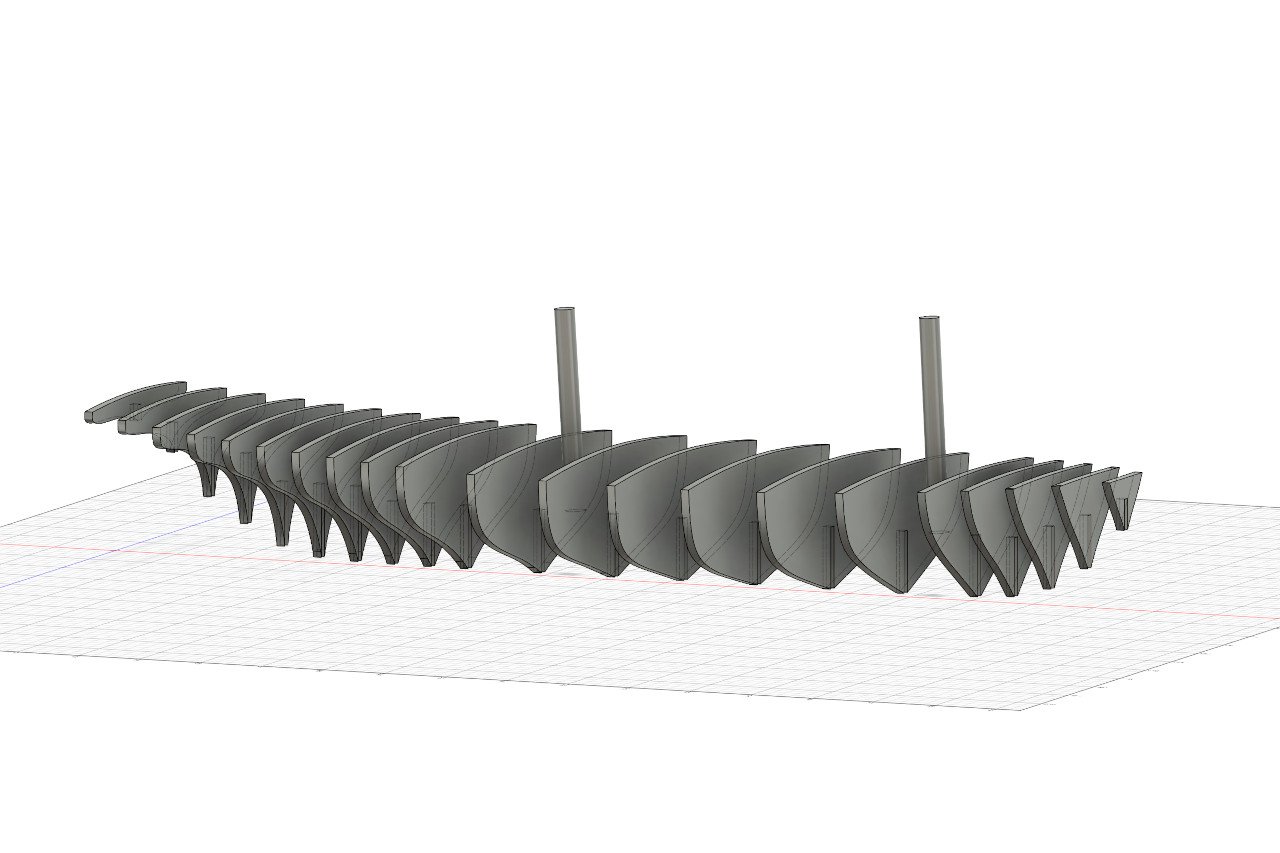
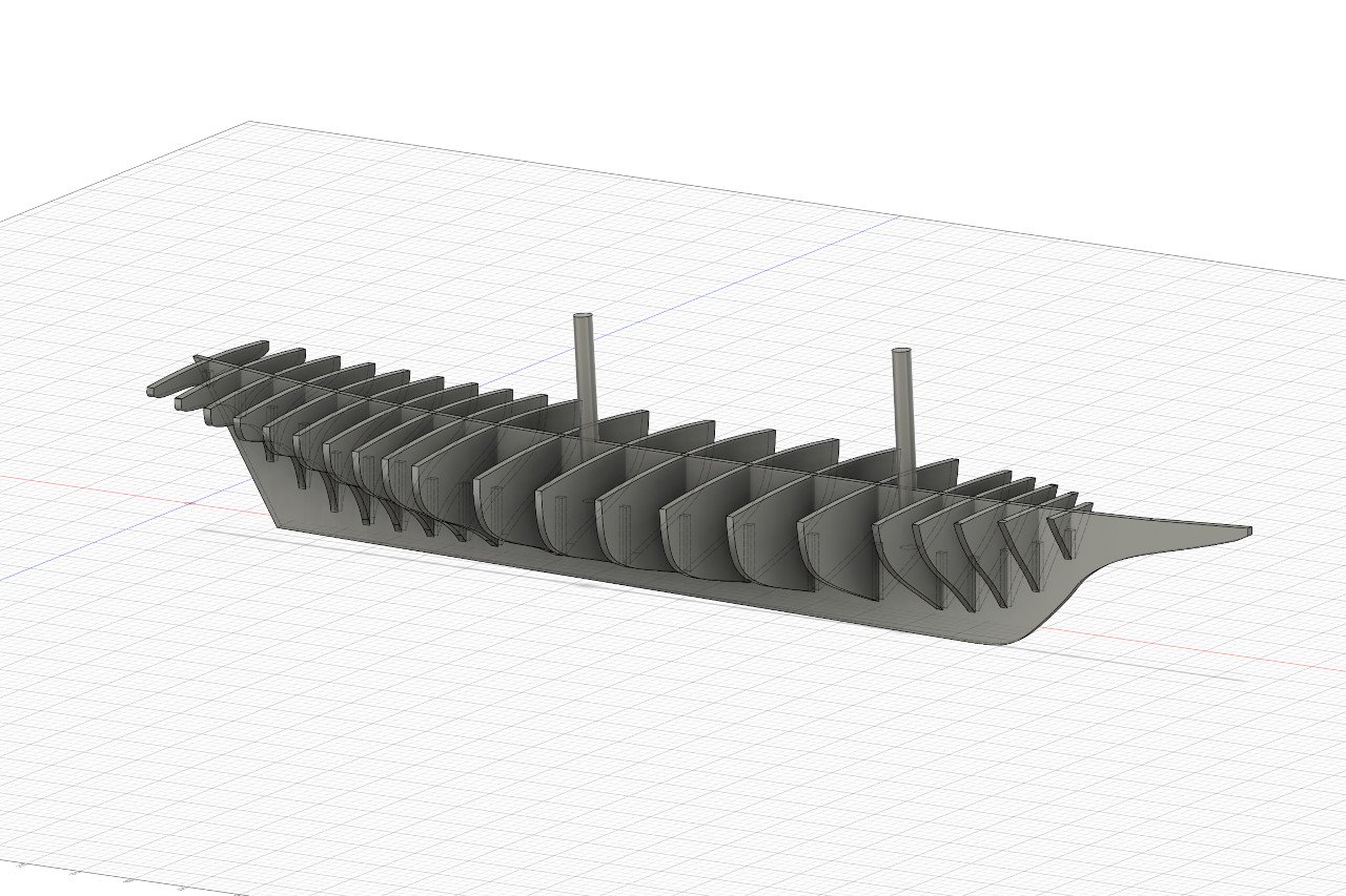
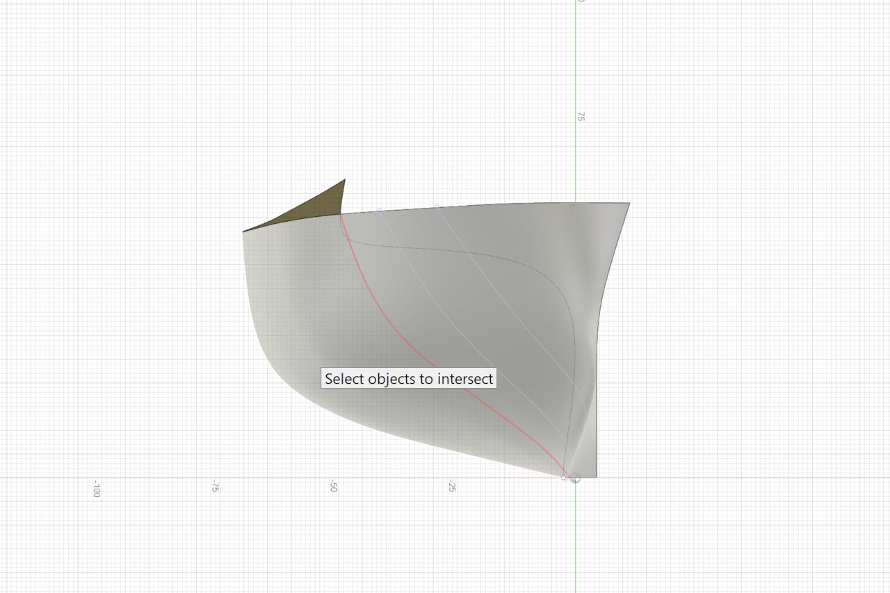
I created cylinders of diameter equal to the dowels I will use for the masts. They were placed at the correct rake and ended where the dowels will end in the hull. I was not satisfied with the hull from before, so I gave it another go. The bow is cleaner and I also extended the shape aft beyond the last station on the plans. This will allow me to identify the shape for a bulkhead as far aft as I'd like. I also extended the deck surface fore and aft so that it would be available for finding the top surface of bulkheads wherever I choose to place them. Now it's time to create the bulkhead shapes. First, I need to choose where the bulkheads will be. There are few restrictions. I started by placing the bulkhead locations on either side of the masts to be sure that there would be space for the bottom ends of the masts. After that, it was generally even spacing, with bulkheads closer together at the bow and stern. This is a lot of bulkheads, but I hope it will make it easier to plank the hull. The process of creating the bulkhead shape is straightforward: Start a new sketch on the plane of the bulkhead. Use the Project/Include -> Intersect tool to acquire the lines of intersection with the hull and deck shapes. (The red line in the image below shows the plane of the bulkhead intersecting the hull.) The result looks like this. I add the notch at the bottom. It is sized to match the thickness of wood sheet. The superfluous overlapping lines are removed. Repeat the process until all the bulkhead shapes are formed. I can thicken these to get an idea of how it'll look. And I quickly sketched out the keel to get a better idea of the final form. This was just a quick shape to visualize how things will look. The final stern post / keel / stem will be a little different. To do next: Add some shapes at the bow to help define its shape. Add pieces to form the transom and stern. Inscribe fairing lines on each bulkhead piece. Inscribe lines on the bulkheads to indicate the line of the wale. Add pieces to hold the masts in place. Finalize the shape of the false keel, add the rabbet, etc.

-
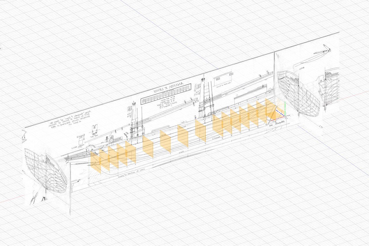
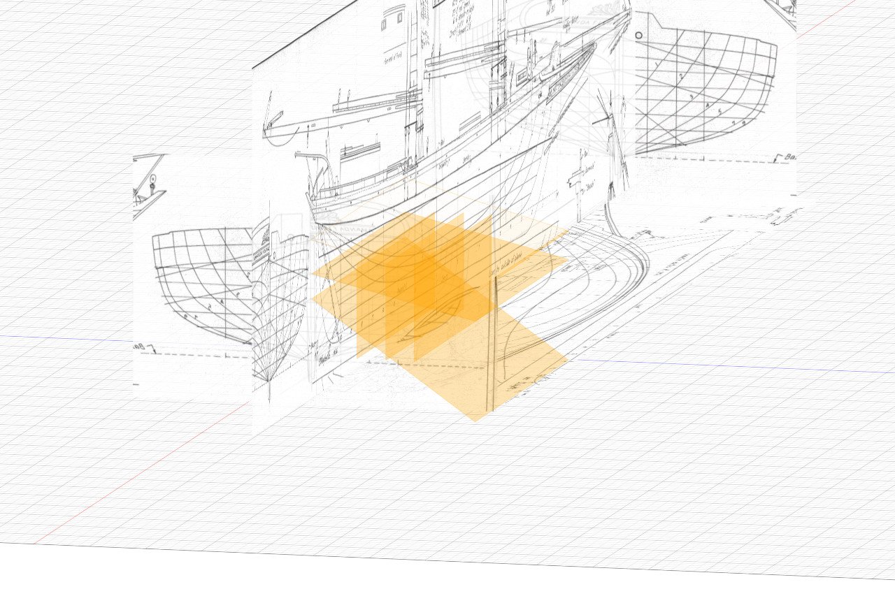
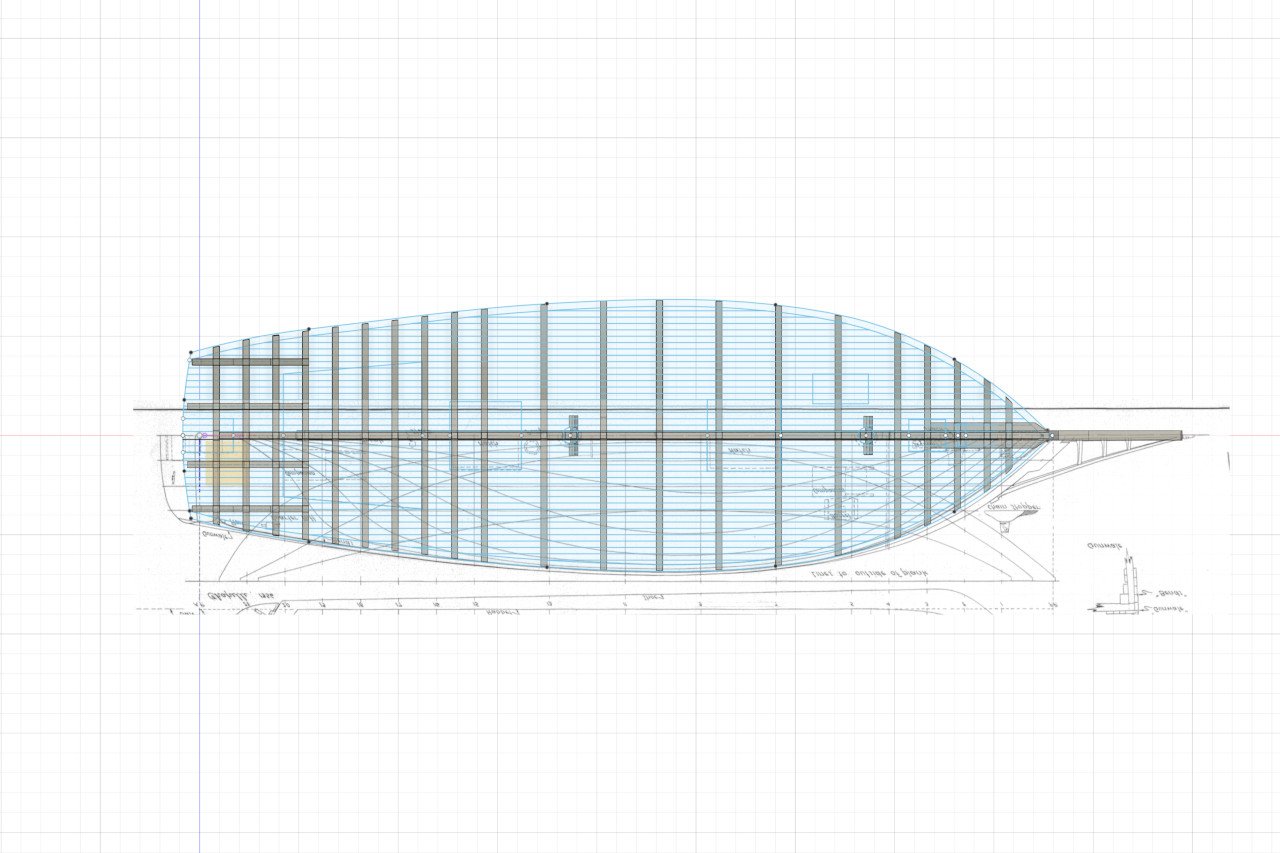
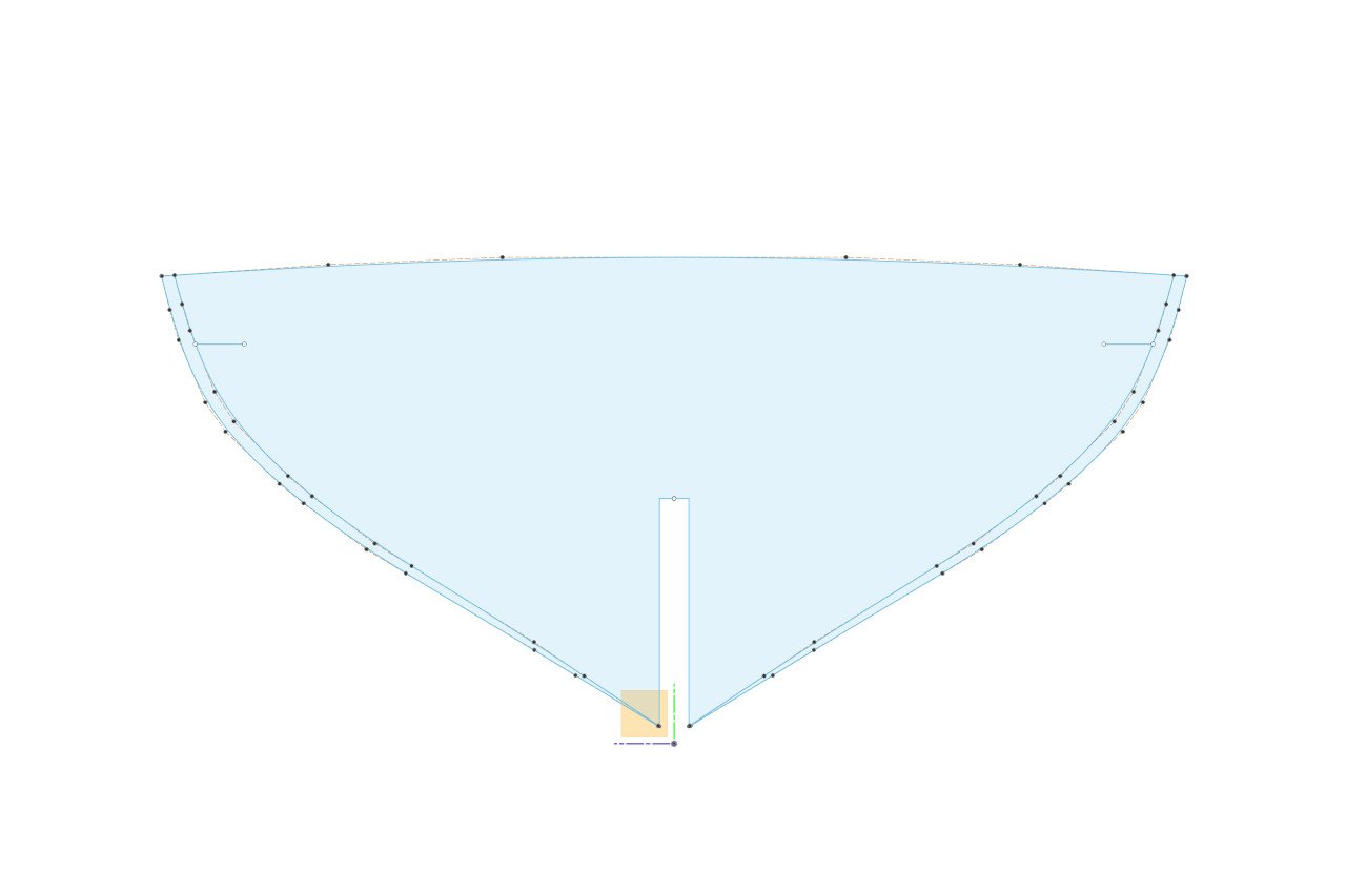
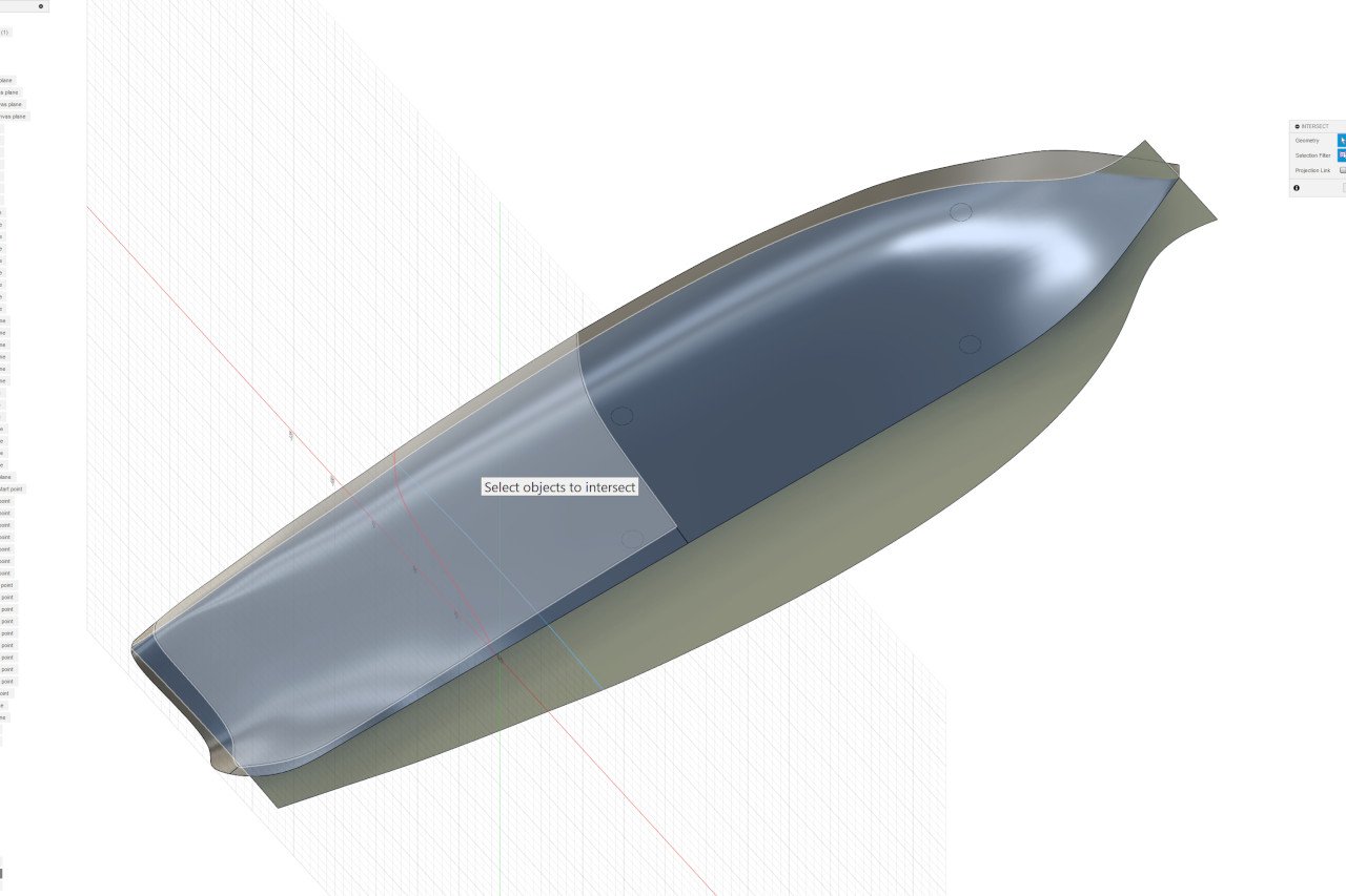
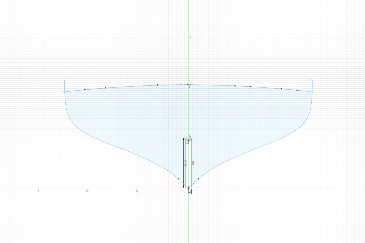
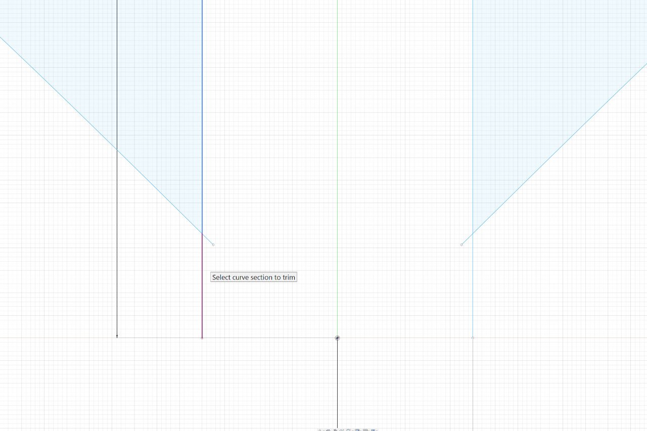
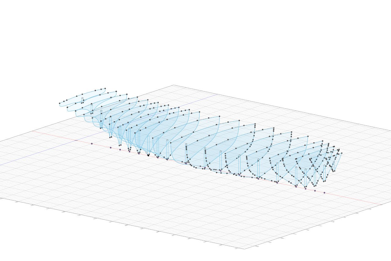
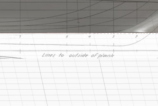
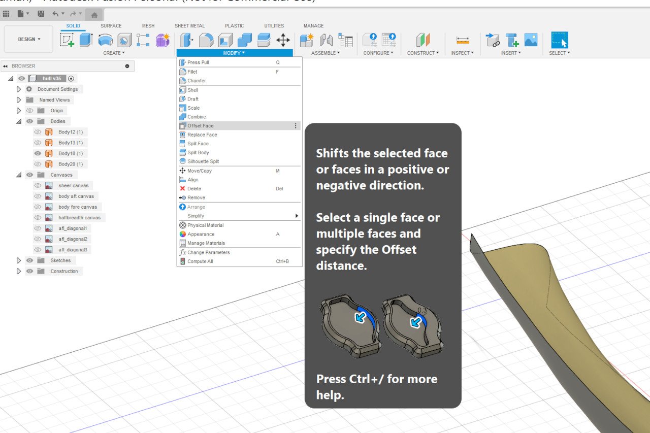
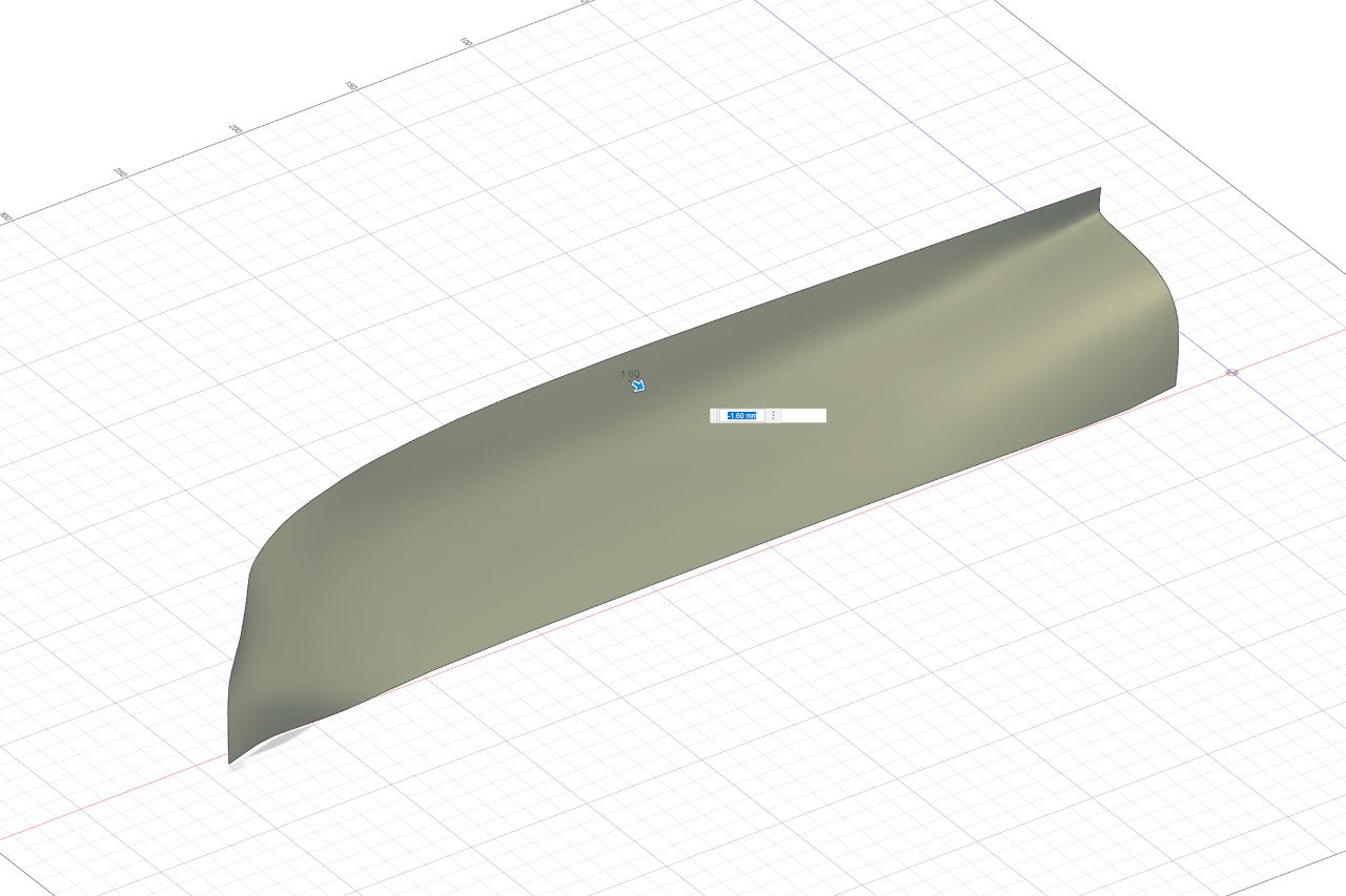
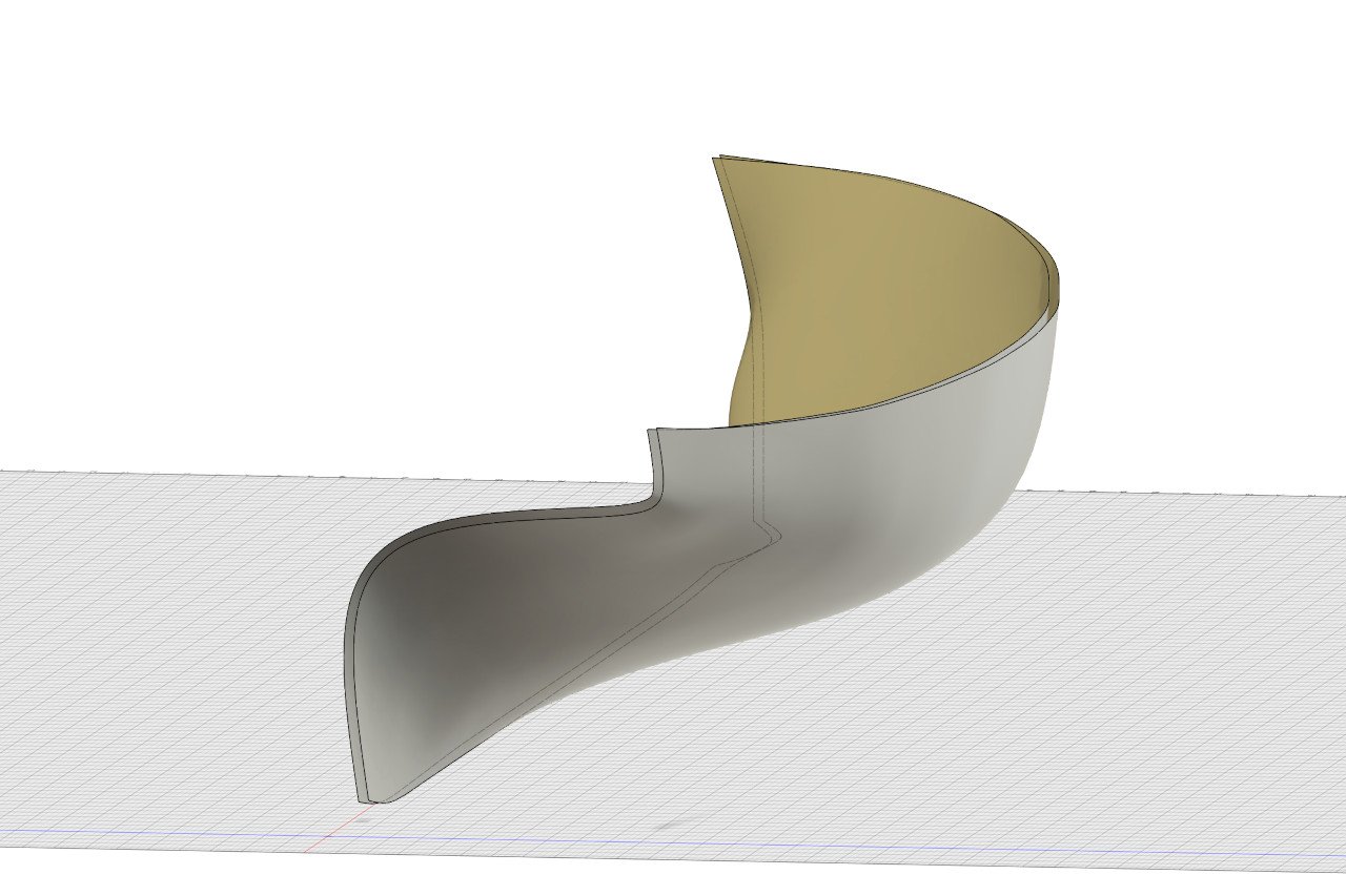
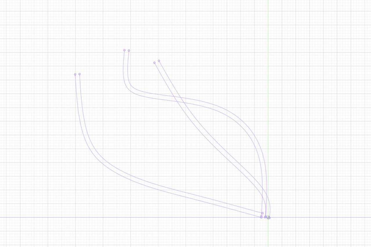
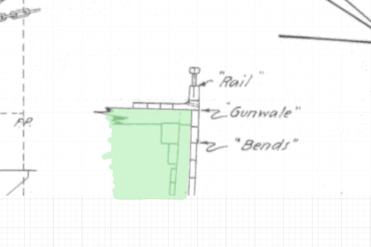
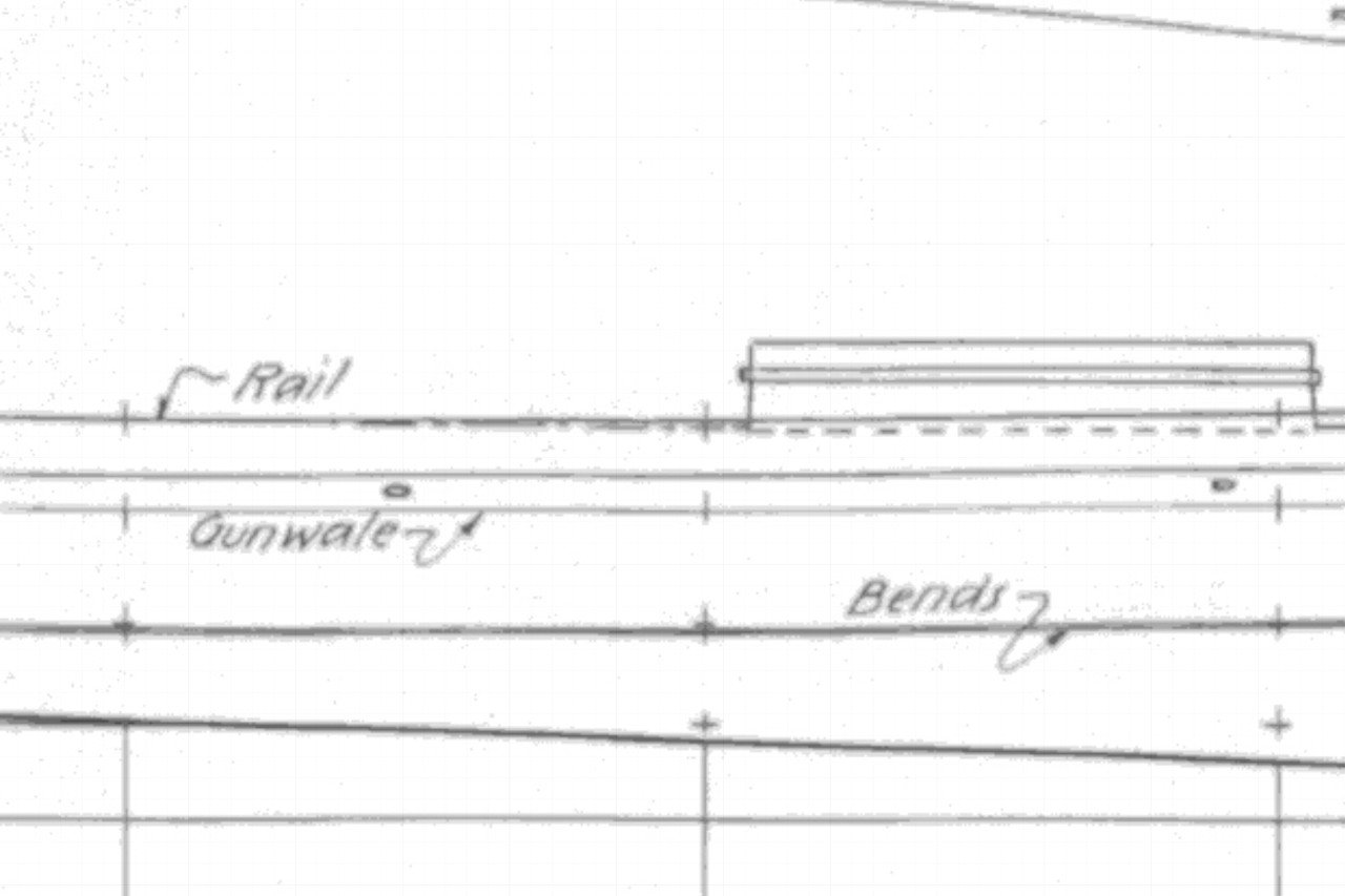
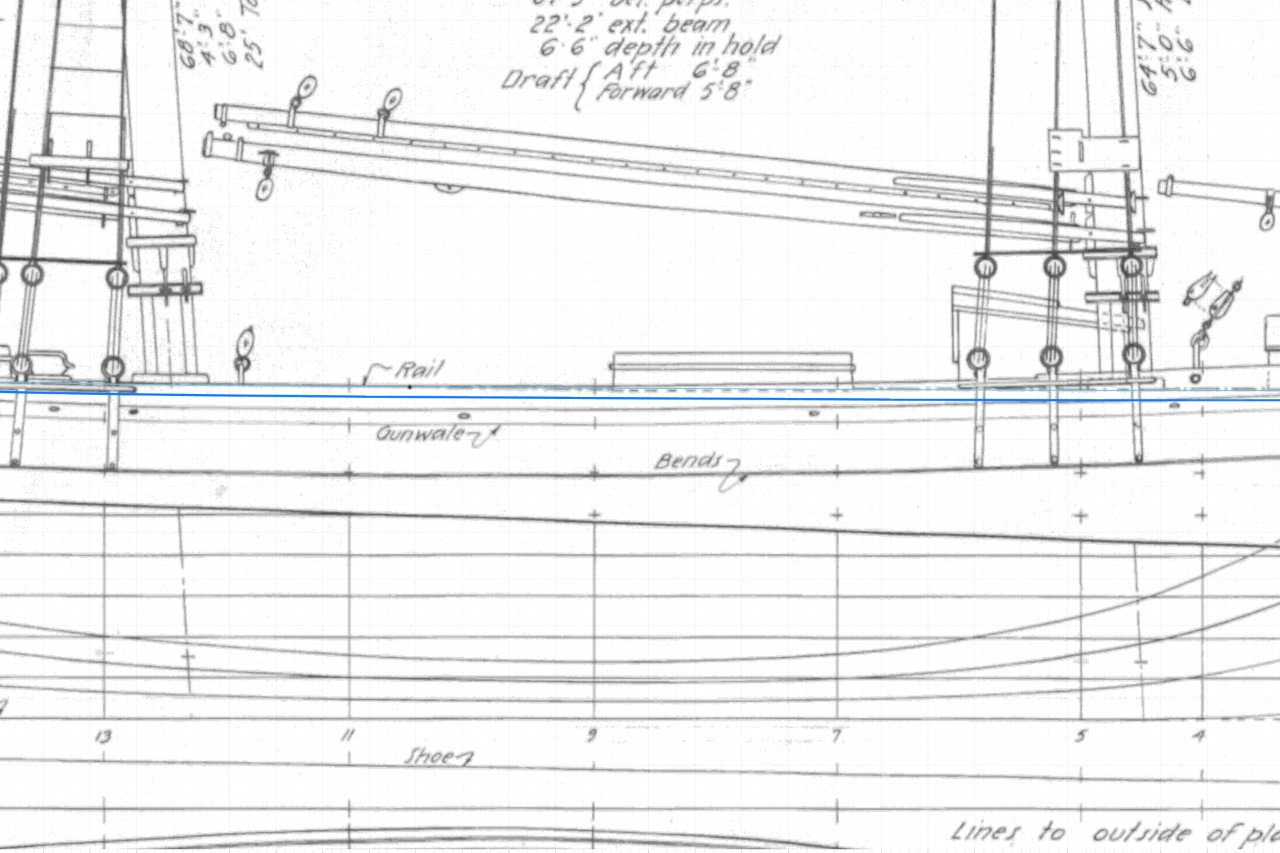
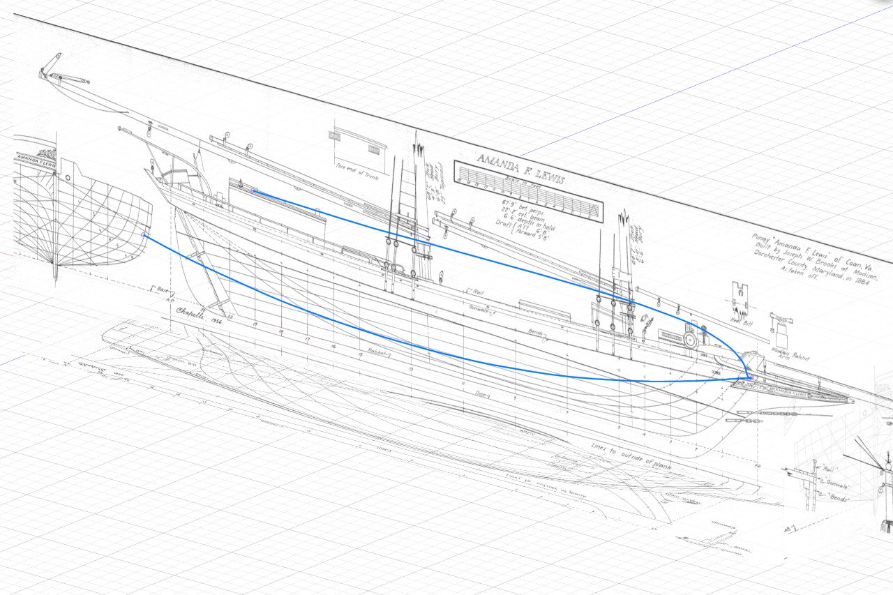
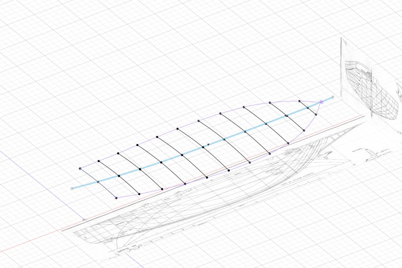
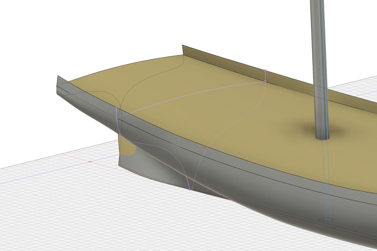
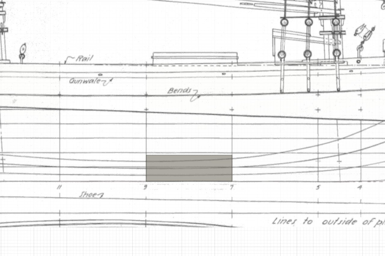
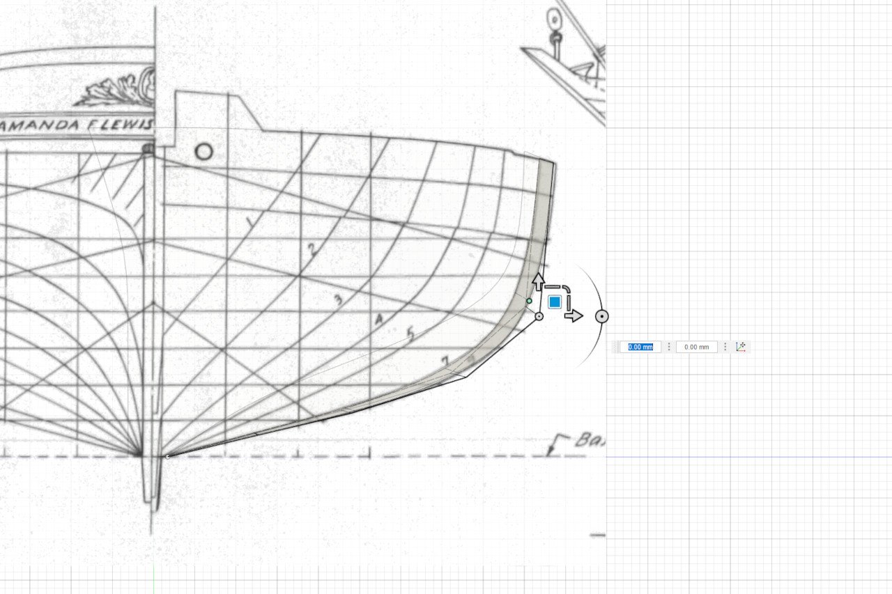
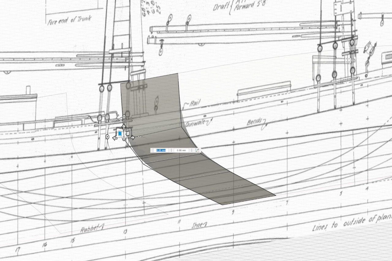
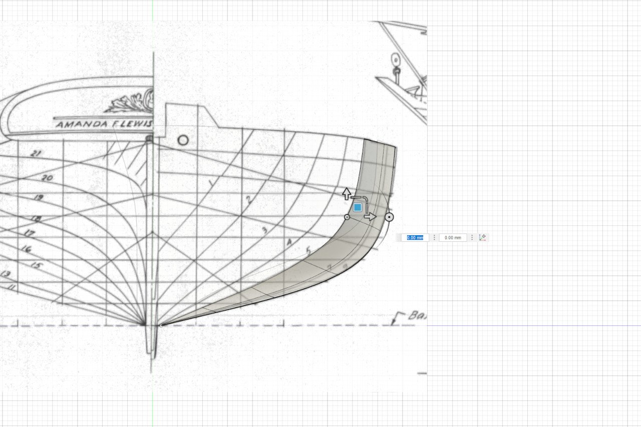
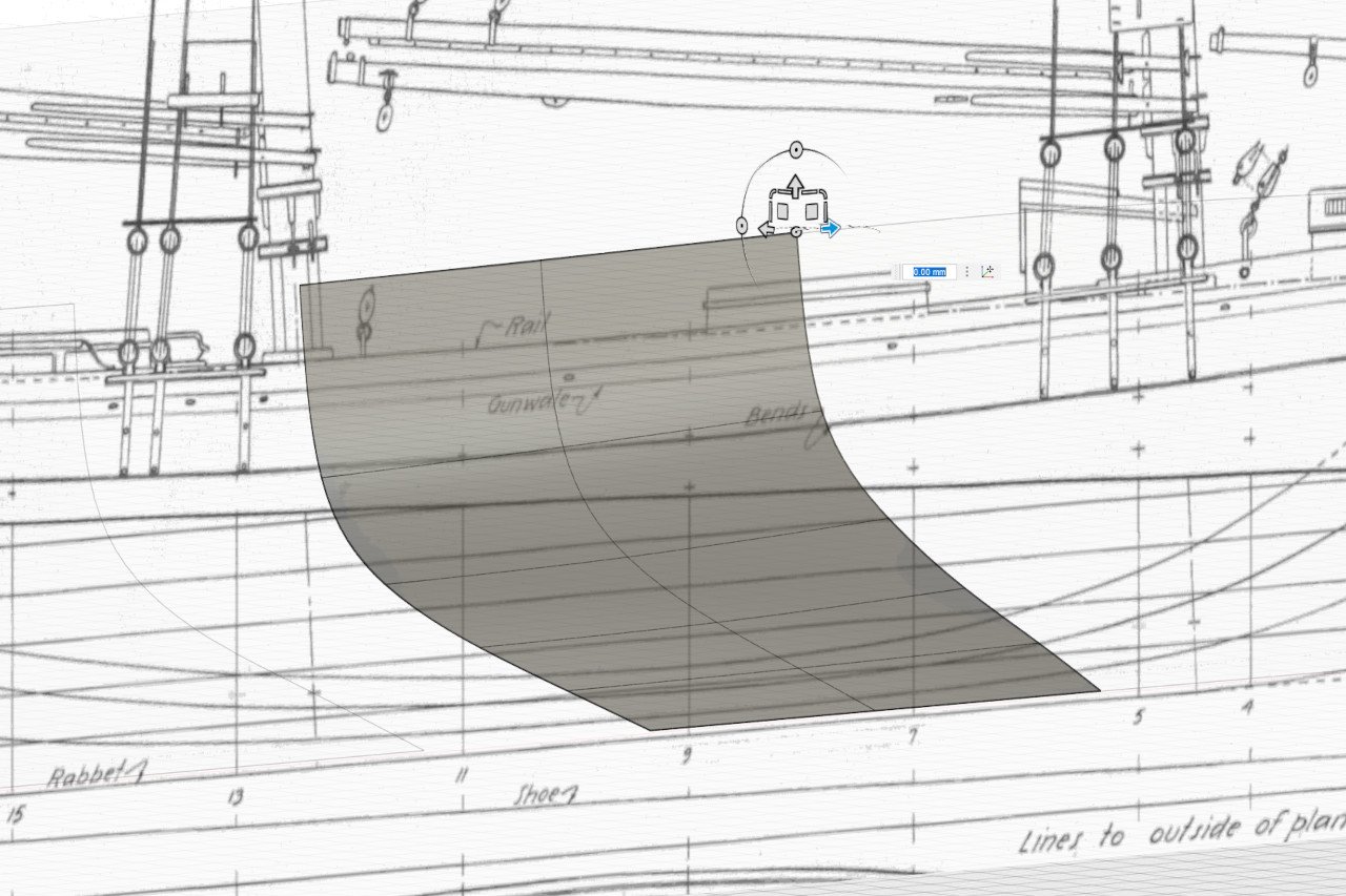
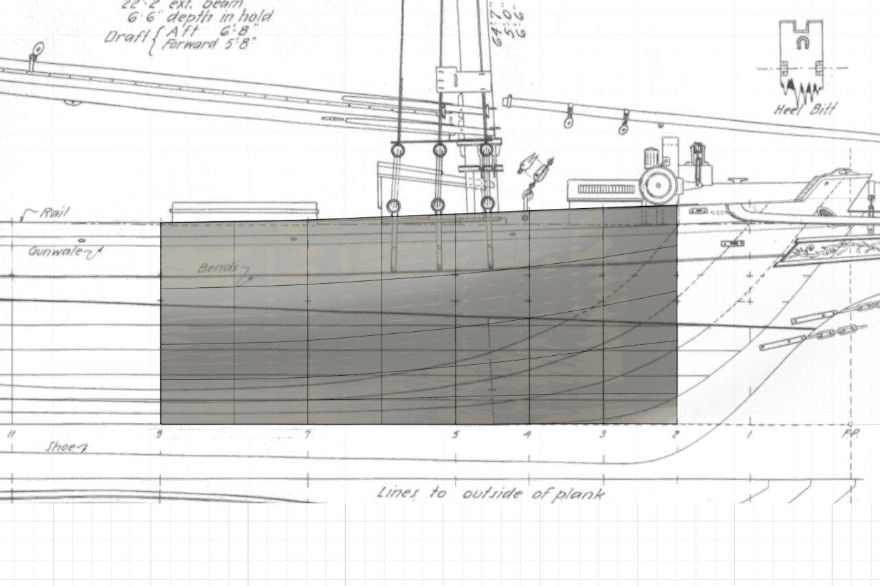
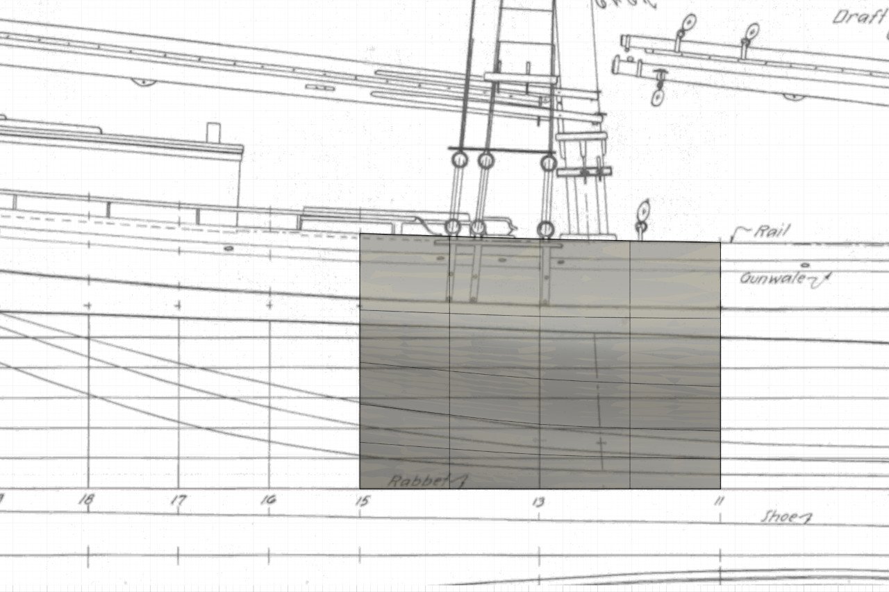
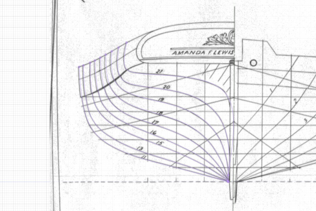
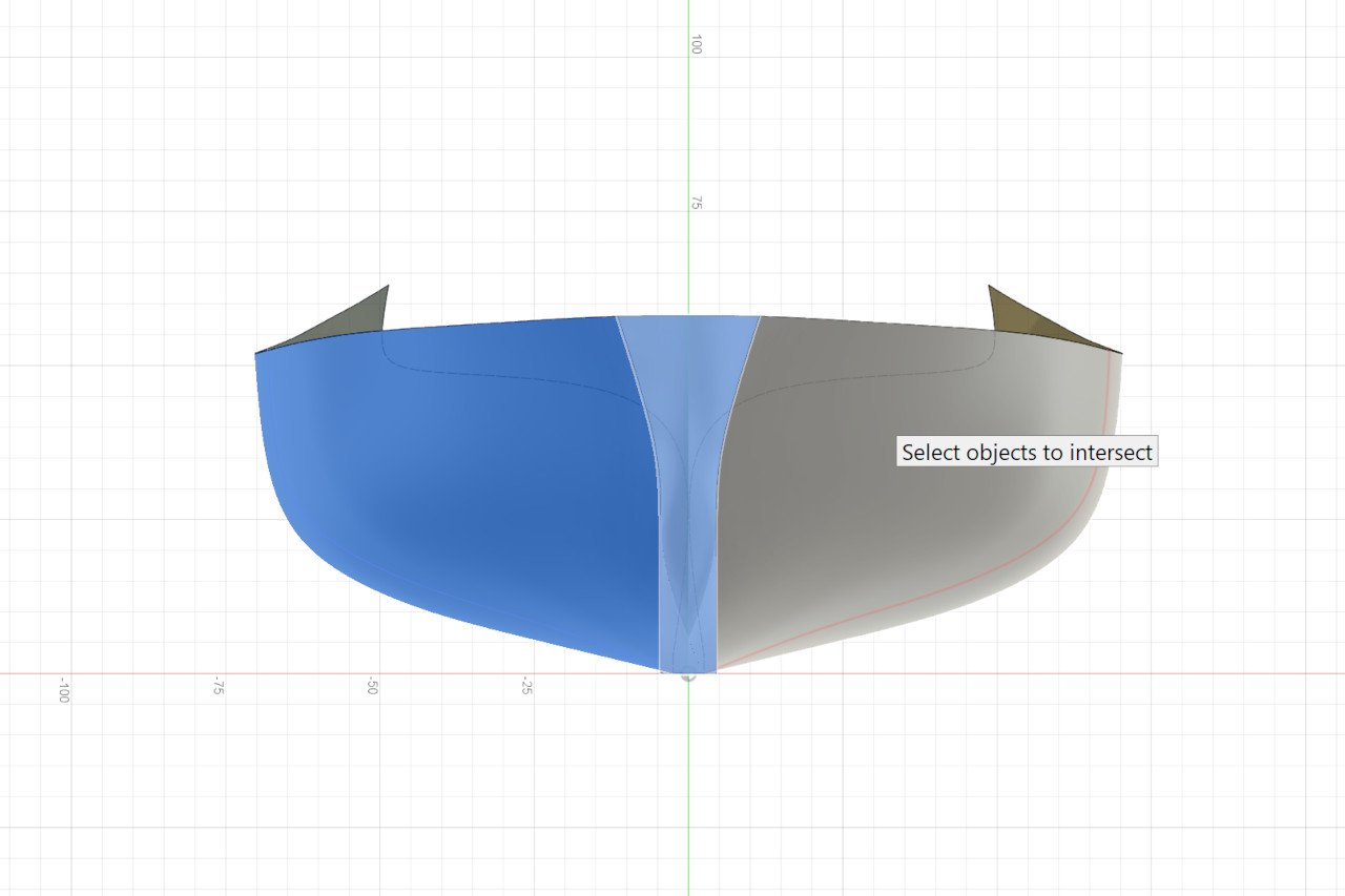
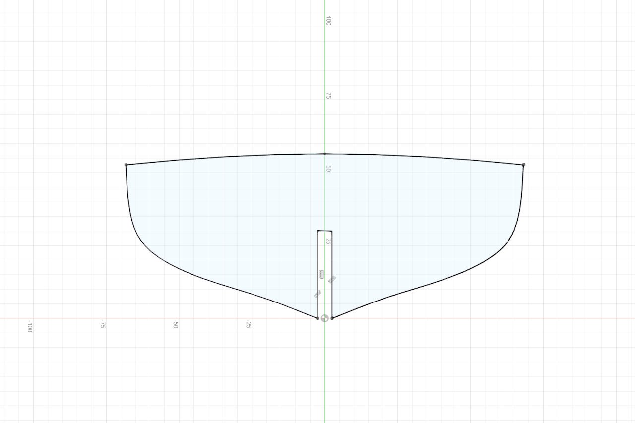
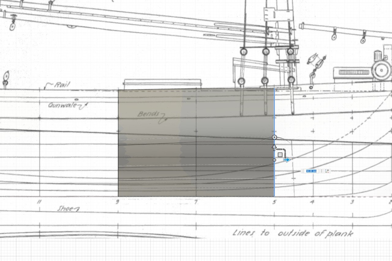
Last time I created a hull form in Autodesk Fusion. At the end of that log, I alluded to an issue with the work I had done so far. The problem that I have, is here on the plans. The lines are to the outside of the hull. That means that if I use the hull form as it is, create bulkheads with it, and then plank the model, it will be wider than it should be. Instead, I need to create bulkheads that represent the hull form at the inside of the hull planking. Fortunately, Fusion has a powerful feature called offset that handles this. It can create a surface offset by a given value that is normal to that surface. So I select my surface and create a new surface offset by the plank thickness. Here are the old and new surfaces. I generated station lines for the old a new surfaces at three points on the hull to show how the thickness is maintained. This diagram from the plans shows a cross section of the hull. You can see how the hull and deck planks lay. Note also the wale or "bends", above which the planking is thicker. The underside of the deck meets the hull planking at the gunwale line. I want to create bulkheads that match the inner side of the hull planking and the underside of the deck planks. I have shaded in green the portion of the target bulkhead shape. The next task will be to define the underside of the deck. Here is a view on the plans from the side. The gunwale is clearly marked. The deck at the center line is indicated with a dashed line. Is that the top of the deck or the underside of the deck planks? I can see that the mast coats are above the dashed line, so it must be the top surface of the deck. Because I need the underside of the deck, I just traced the line of the deck surface at the centerline and then created a new line offset down the thickness of the deck planking. Then I found the intersection of the edge of the underside of the deck at the waterway by intersecting the gunwale curve with the hull form. (I mirrored the hull form before doing this, so I could get the curves on both sides. Then I found the points where the odd numbered stations intersect with the gunwale and centerline at the underside of the deck. I joined these points with a curve. Here it is at station 1. There is almost no deck camber here at the bow. And these are the camber curves (black lines) for all the odd numbered stations. Using those curves, I created a surface which represents the underside of the deck. The surfaces are displayed here. And here is an example bulkhead (light purple lines) created by finding the curves at the intersection of the hull and deck surfaces. (As you can see, I also added some dowels for the masts.) This is good progress. I'm just about ready to create bulkheads. I still need to work out the form of the stern, which I dread, so I'll be putting that off.
-
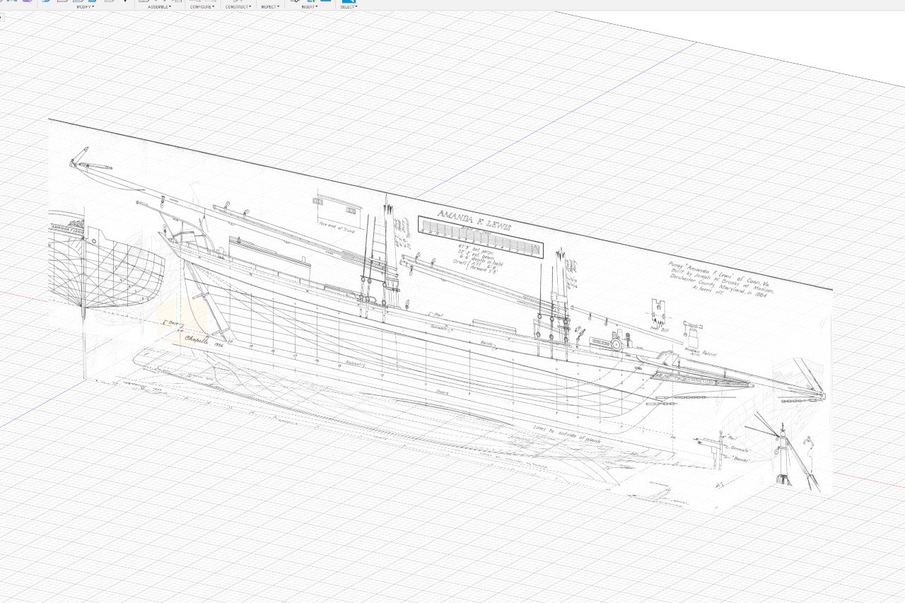
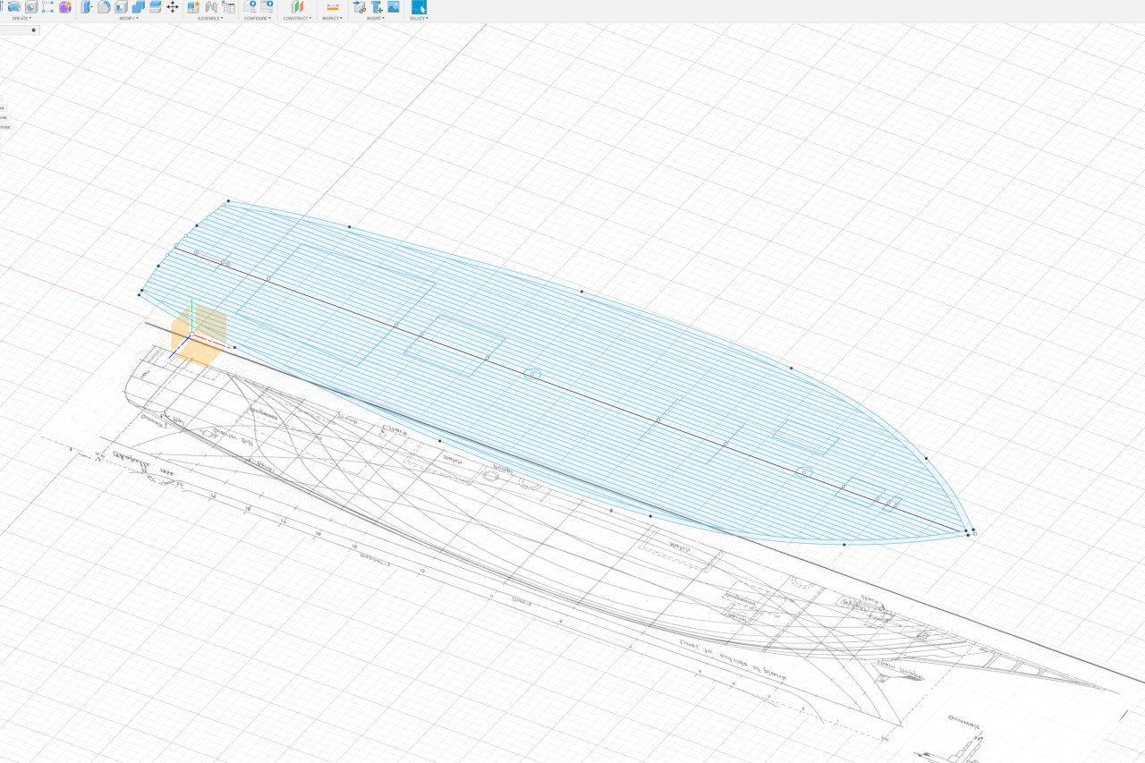
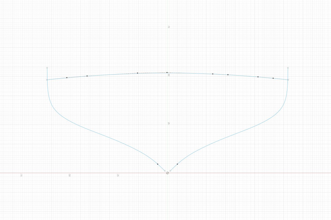
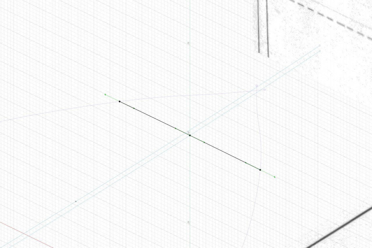
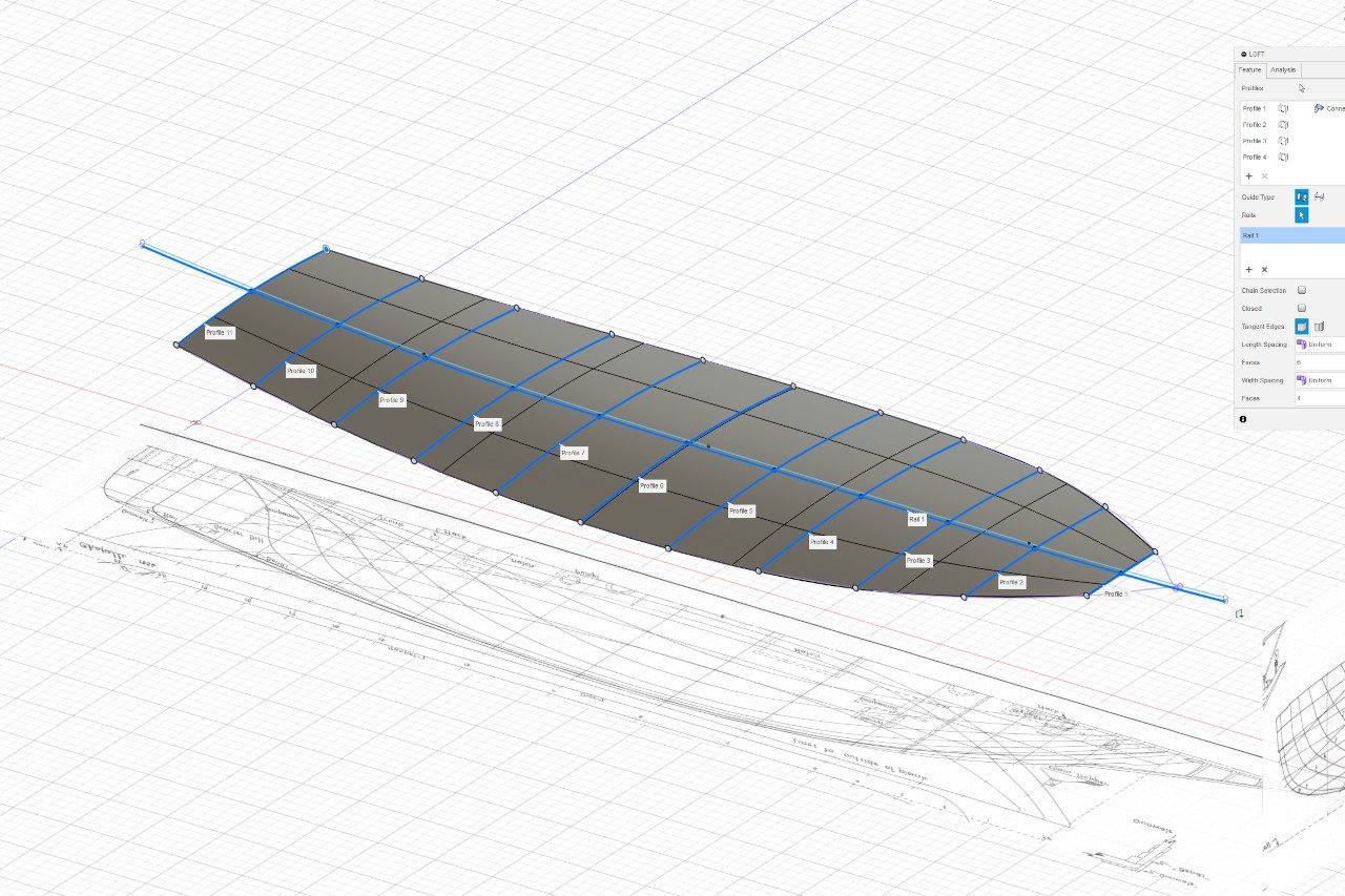
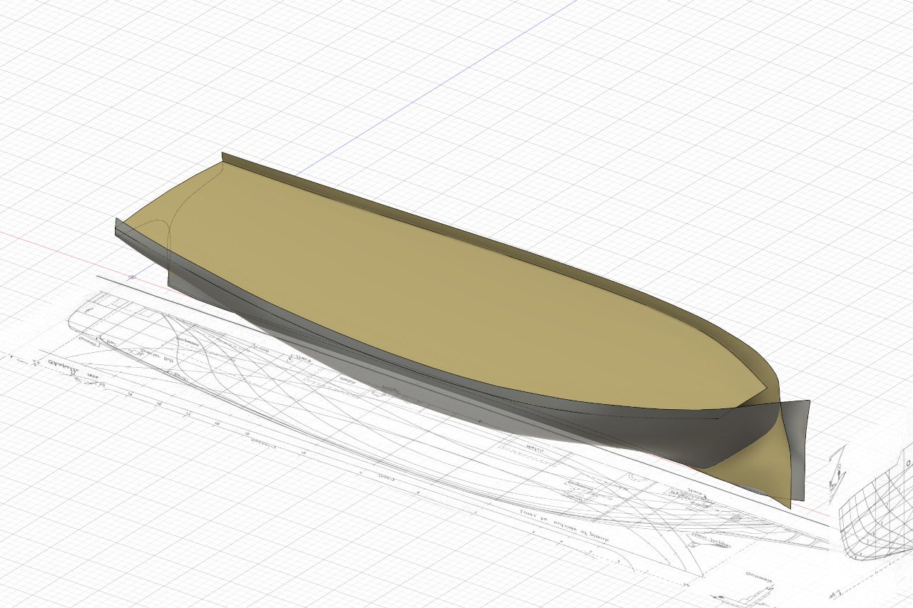
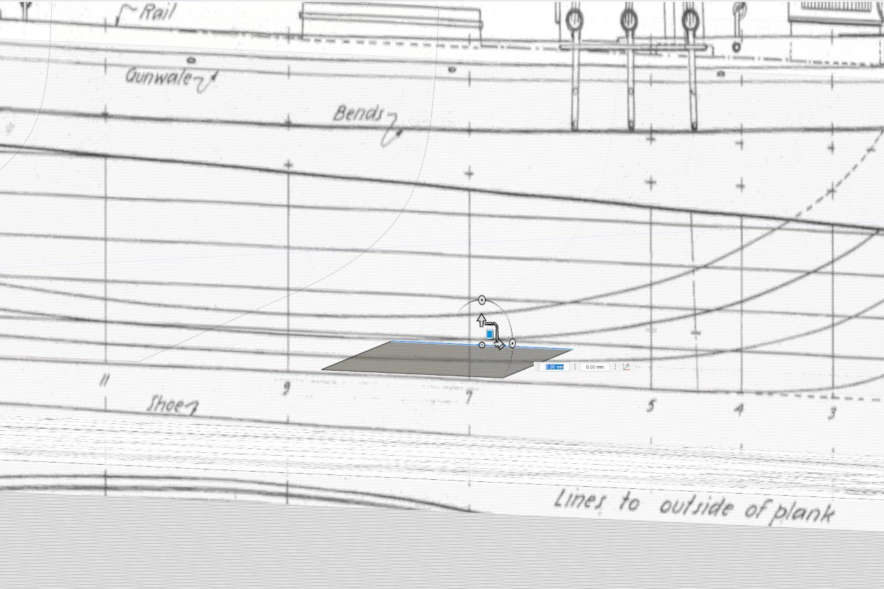
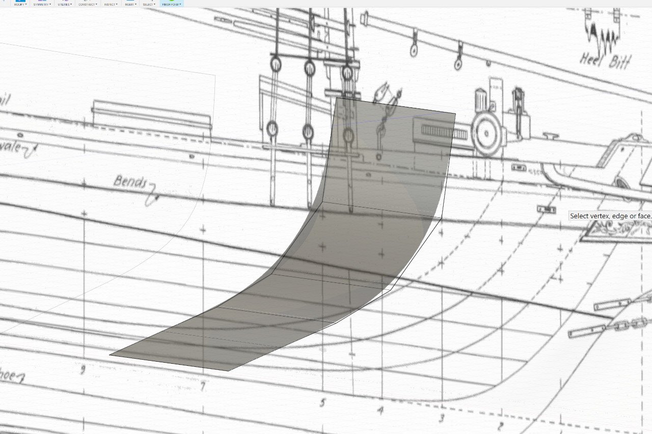
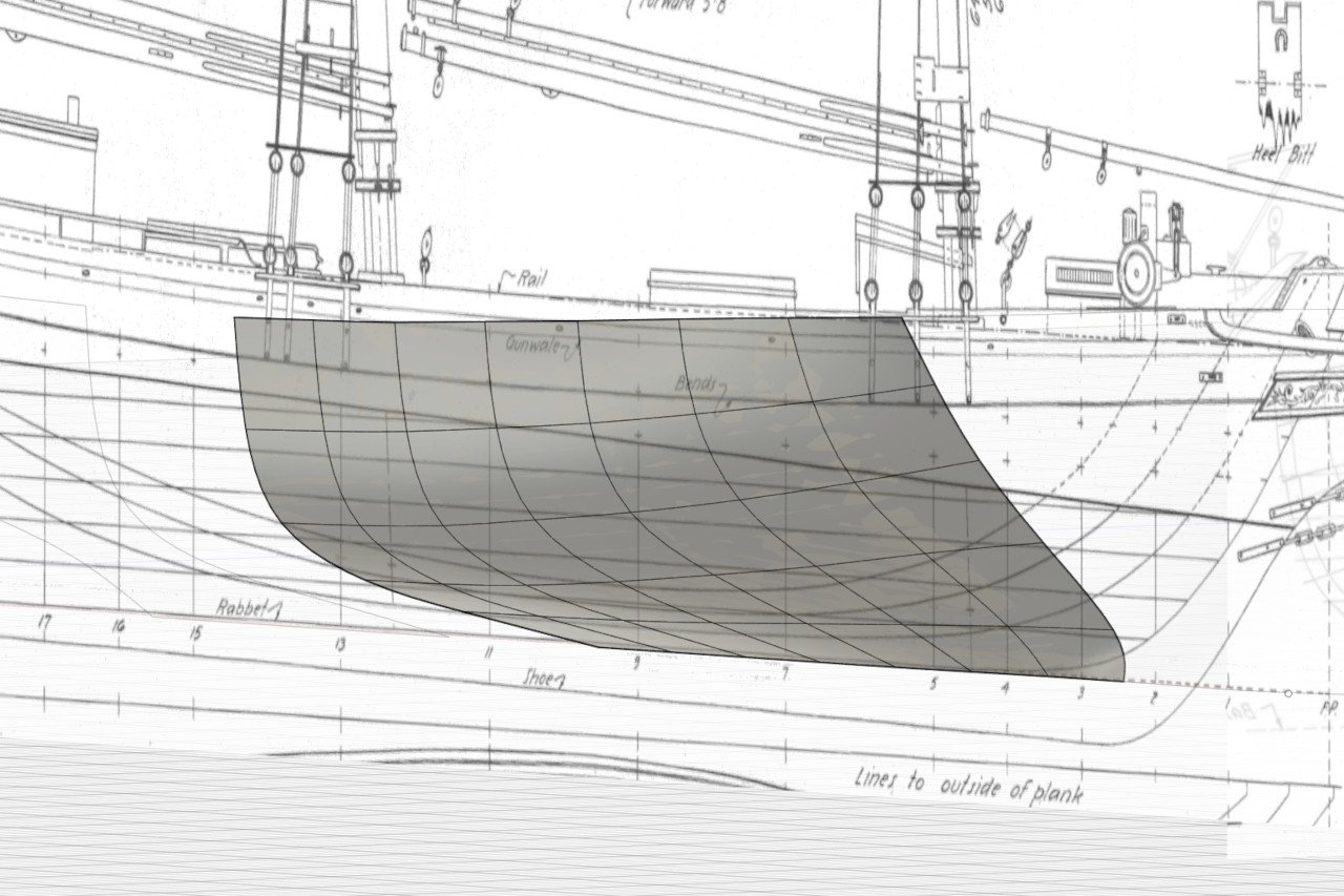
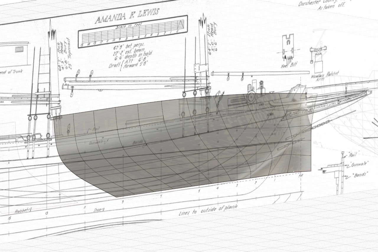
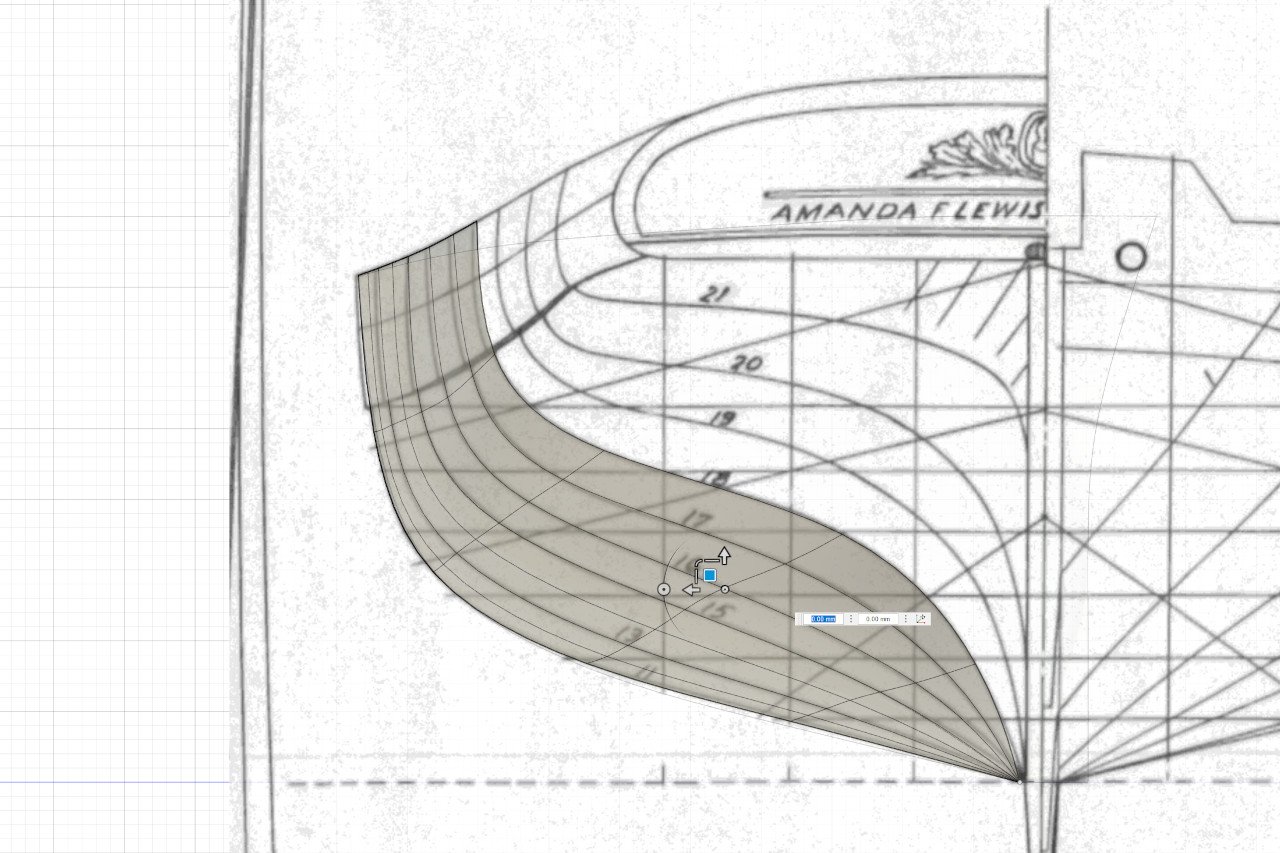
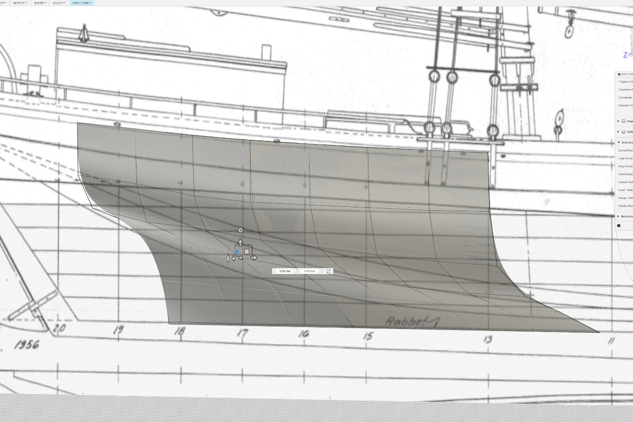
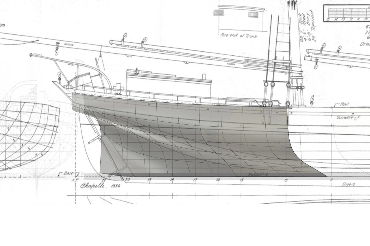
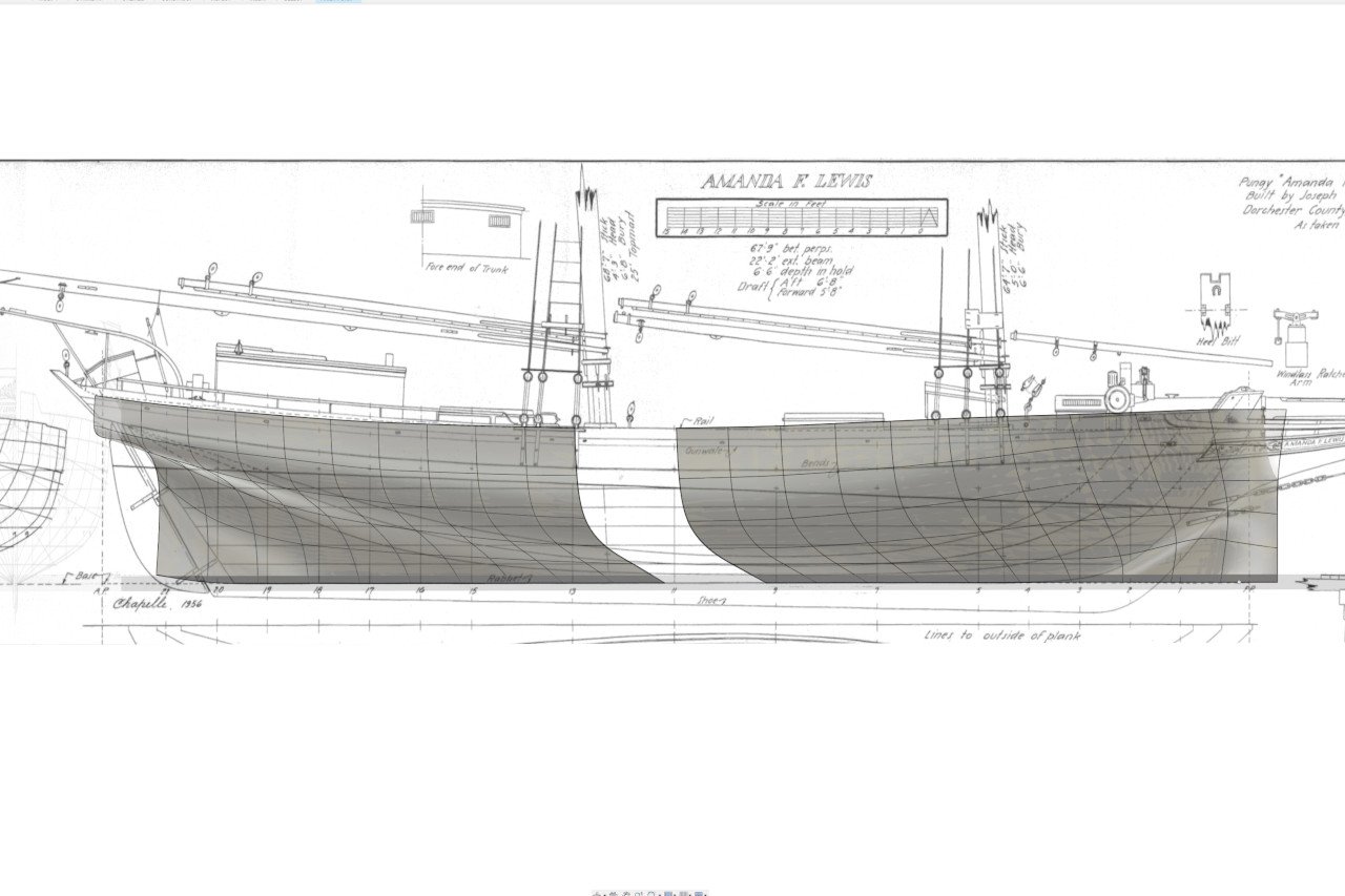
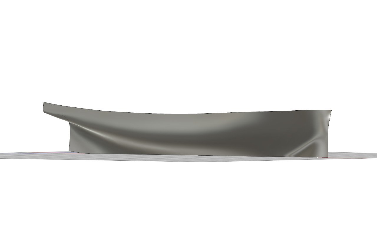
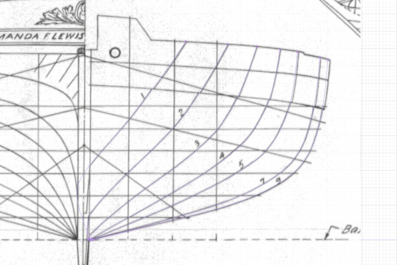
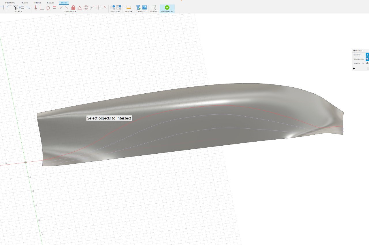
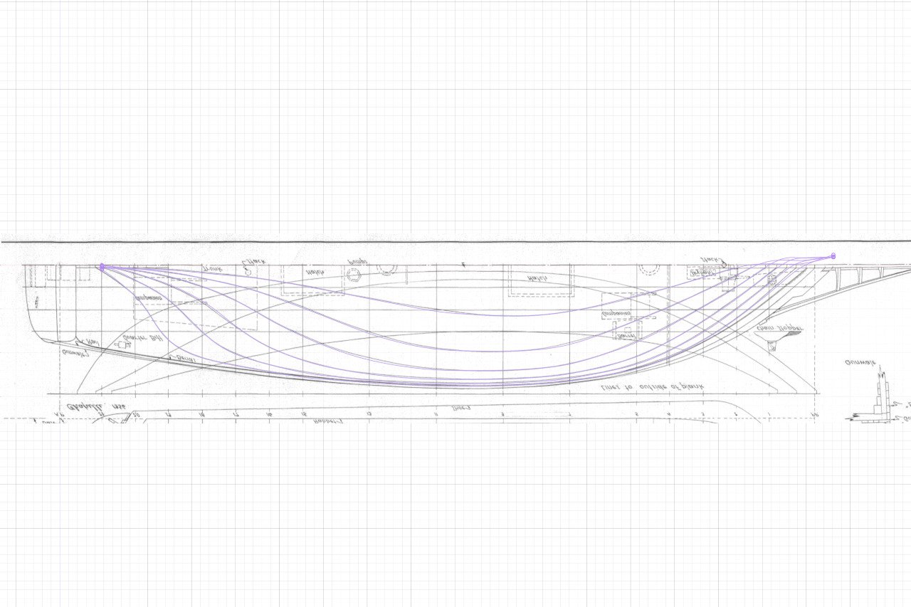
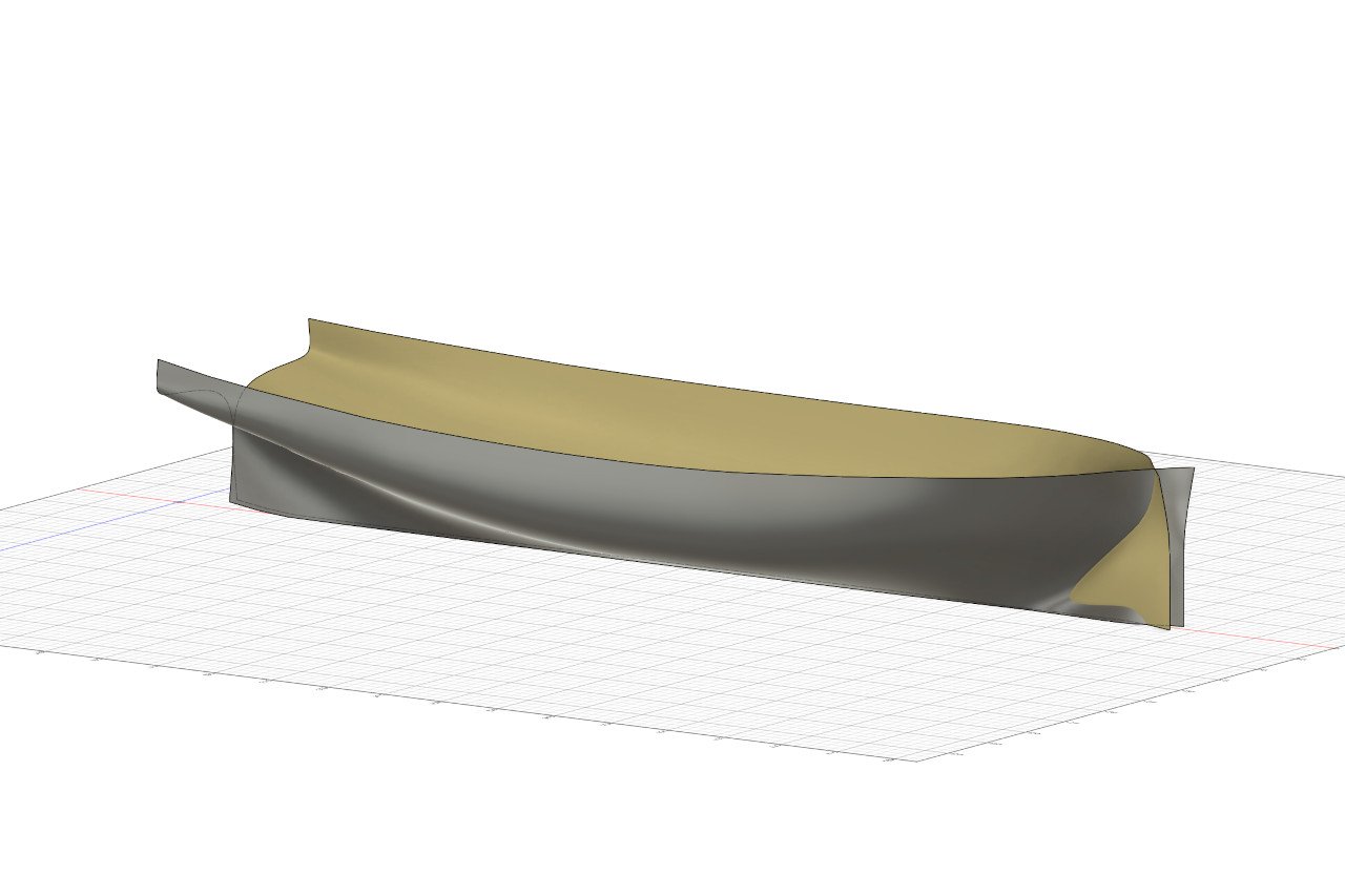
Let's use the imported plans to create the shape of the hull. I start by going into Fusion's Form environment, which allows the creation of smooth objects out of t-splines. It begins with a single face, strategically placed between stations 7 and 9. The face is tilted outward at an angle consistent with the deadrise at that point on the hull. And then the face is extruded until there are five faces total. I found through previous experimentation that five was a good number. Fewer faces and I didn't have enough control points to create a matching curve for each station. More faces and the curves started to get wobbly. This picture shows how the grid of control points and lines (black lines) define the shape in gray. In most of the later images, I have hidden the control grid so that only the hull surface is displayed. Each edge was adjusted to conform to the hull curvature at the stations (7 and 9 in this case). Here is the same viewed from a different angle. Then the forward edges are extruded toward the bow to create the next section. And the new edge is matched to the curvature. And the same procedure was repeated for each station going forward. Note that I subdivided the grid between stations 7 and 9, and between 5 and 7, so that the spacing between grid pieces would remain consistent. Failure to do this caused the grid to abnormally stretch in a disproportional manner as new stations were added. It's starting to get a nice shape. Trying to get the shape right at the bow was trouble. There is probably a clean way to end the form in a shape that matches the curve of the stem, but I don't know enough about the Form modeling environment yet to do it. Instead, I just continued to extrude the form out and tried to match the correct form at the bow. There is some pinching and distortion of the form here, but that portion of the form is beyond the boundaries of the actual hull, and none of the shape at that point will be used. So it doesn't really matter. With the forward portion of the hull complete, I started the same process working aft. Here it is after a few sections are completed. And compete all the way to the final recorded station. I'll have to wing it later to capture the shape of the stern. Now I have two halves. It was necessary to work in two pieces separately, because if I tried to create it all at once, the forward pieces would, in a head-on view, obscure the aft pieces, making it impossible to view them as I worked on them. There is a feature to merge edges, which I used to unify the two pieces. After exiting the Form environment, it looks like this. How accurately does the shape conform to the lines of the hull? Well, we can validate it by generating new lines and comparing them to the plans. Fusion has a great feature that lets you plot the intersection of a form and a plane. Let's do that, first with the section lines. In the image below, I have already plotted stations 1 and 2 (purple lines) and I'm currently plotting the intersection of station 3 (red line). After plotting all the forward sections (purple lines) they can be compared to the plans. And the same for the aft stations. It looks good. Let's check the waterlines too. Below, I waterlines 1 and 2 (purple lines) have already been plotted, and I am plotting waterline 3 (red line). Now all the waterlines are compared to the plan. It's not 100% perfect, but at this scale, the deviation is no more than a millimeter. I'm satisfied. So, what's the point? First, let's mirror the hull shape. Let's consider how this can be used to create a plank-on-bulkhead model. I can choose any point along the length of the hull for a bulkhead. At the point where I want a bulkhead, I can plot the intersection of the hull form and the bulkhead plane. Add the deck camber and a notch, and I have a pattern for cutting out. So I'll need to decide how many bulkheads I want and where they will be. I also need to sort out the exact camber of the deck. But there is one big problem with my hull form that means I can't use it until it's addressed. If you've been reading all the notes on the plans, maybe you've noticed what I need to take into account. This has been a big update, so that issue will be saved for next time. Thanks for reading this far.
-
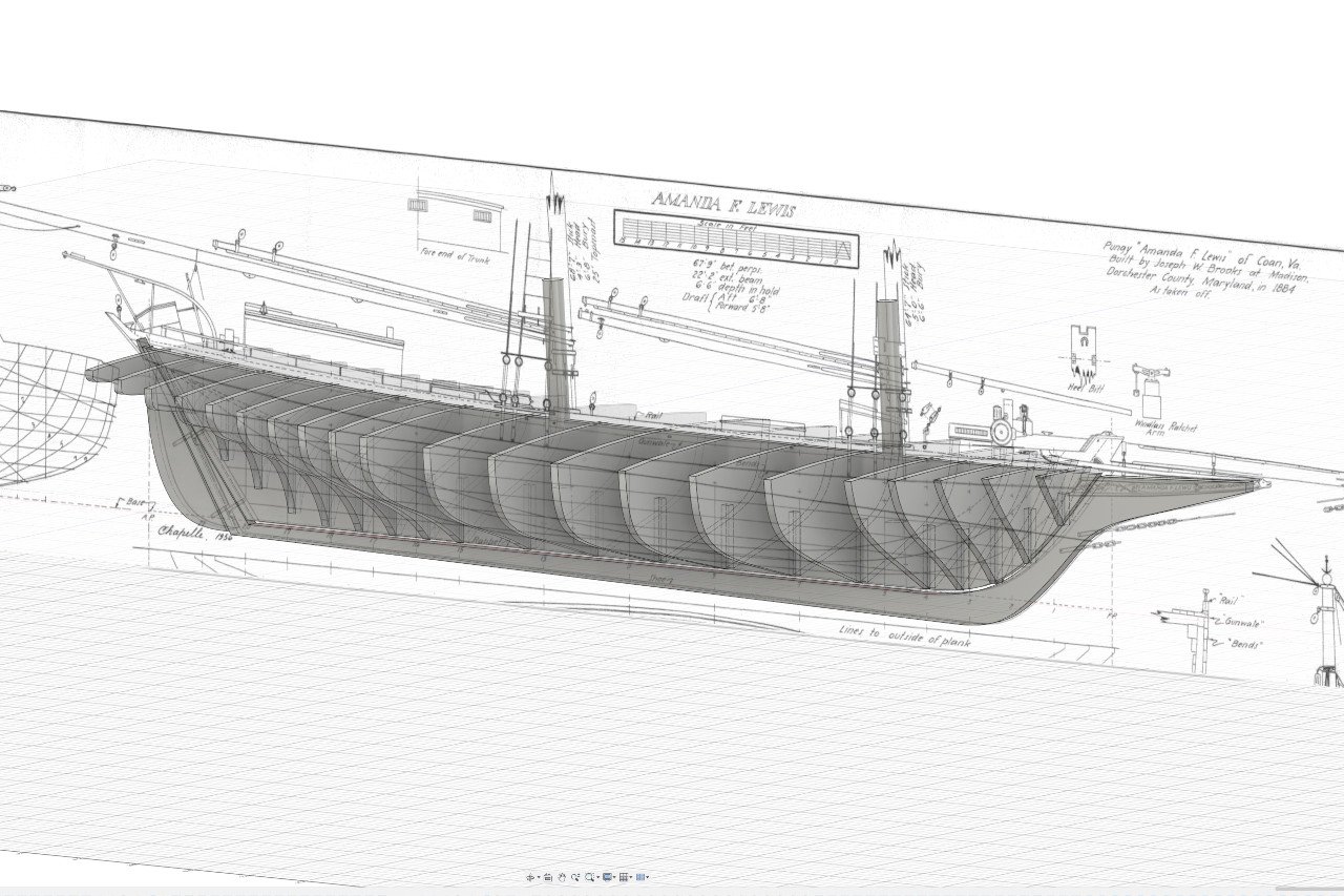
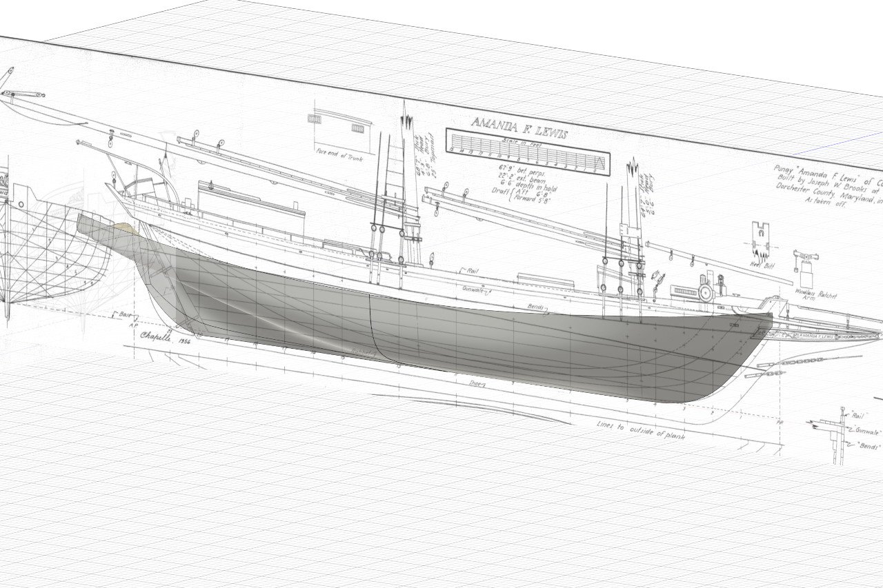
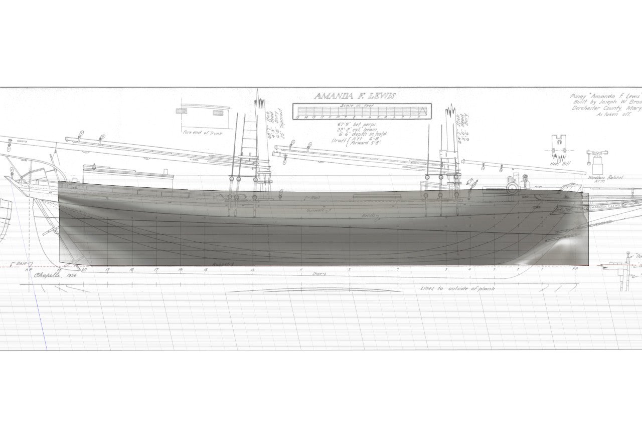
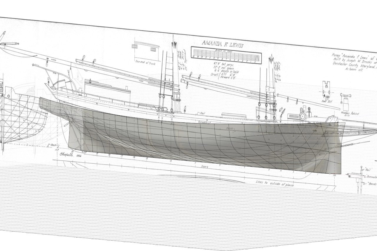
I order the Amanda F. Lewis plans from the Smithsonian. The ship was surveyed as part of the Historic American Merchant Marine Survey in 1936 or 1937. H. I. Chapelle drew the plans in 1956 based on that survey. And, wow, they're big. The scale of the plans is 1:32. Hmm, if I made the model in that scale, it would be just about 1 meter from tip of bowsprit to tip of boom... Tempting, but I think a model that large would trigger a spousal veto, so that's a no-go. 1:48 is what it'll be. I put the plans on one wall and photographed them from across the room. The various views were put into separate image files and brought into the Autodesk Fusion environment. Offset planes were created for each station position. As well as for each waterline. And for the buttock lines and diagonals too, though they might not be used. And with that, the 3D environment is ready for design work.