HOLIDAY DONATION DRIVE - SUPPORT MSW - DO YOUR PART TO KEEP THIS GREAT FORUM GOING!
×


SardonicMeow
-
Posts
333 -
Joined
-
Last visited
Content Type
Profiles
Forums
Gallery
Events
Everything posted by SardonicMeow
-
 Welcome to my build log for the Amanda F. Lewis, built in 1884. She was a pungy, a type of schooner unique to the Chesapeake Bay. This will be a plank-on-bulkhead build at 1:48 scale. There will be lots of 3D design, there will be pirates, maybe a road trip or two, no doubt plenty of successes and mistakes. I hope you will follow along. Below: 1933 painting of the Amanda F. Lewis by Louis Feuchter, painting photographed by me at the Chesapeake Bay Maritime Museum. It shows the vessel during her later years.
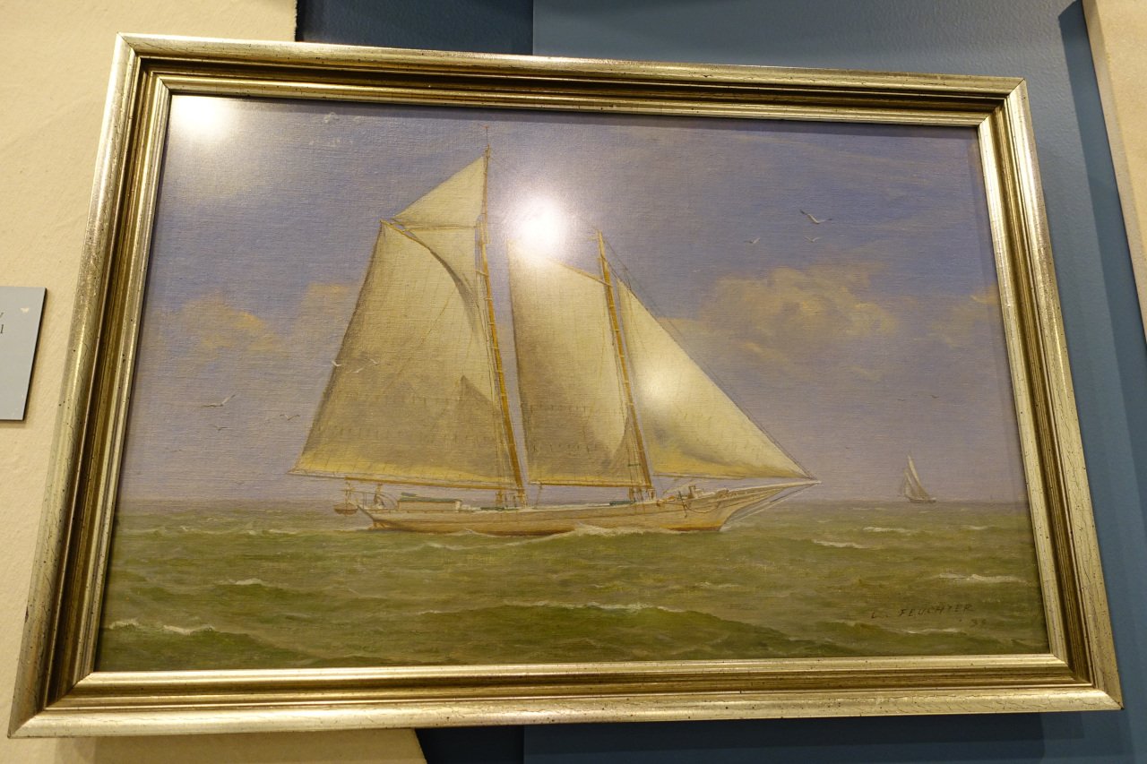
-
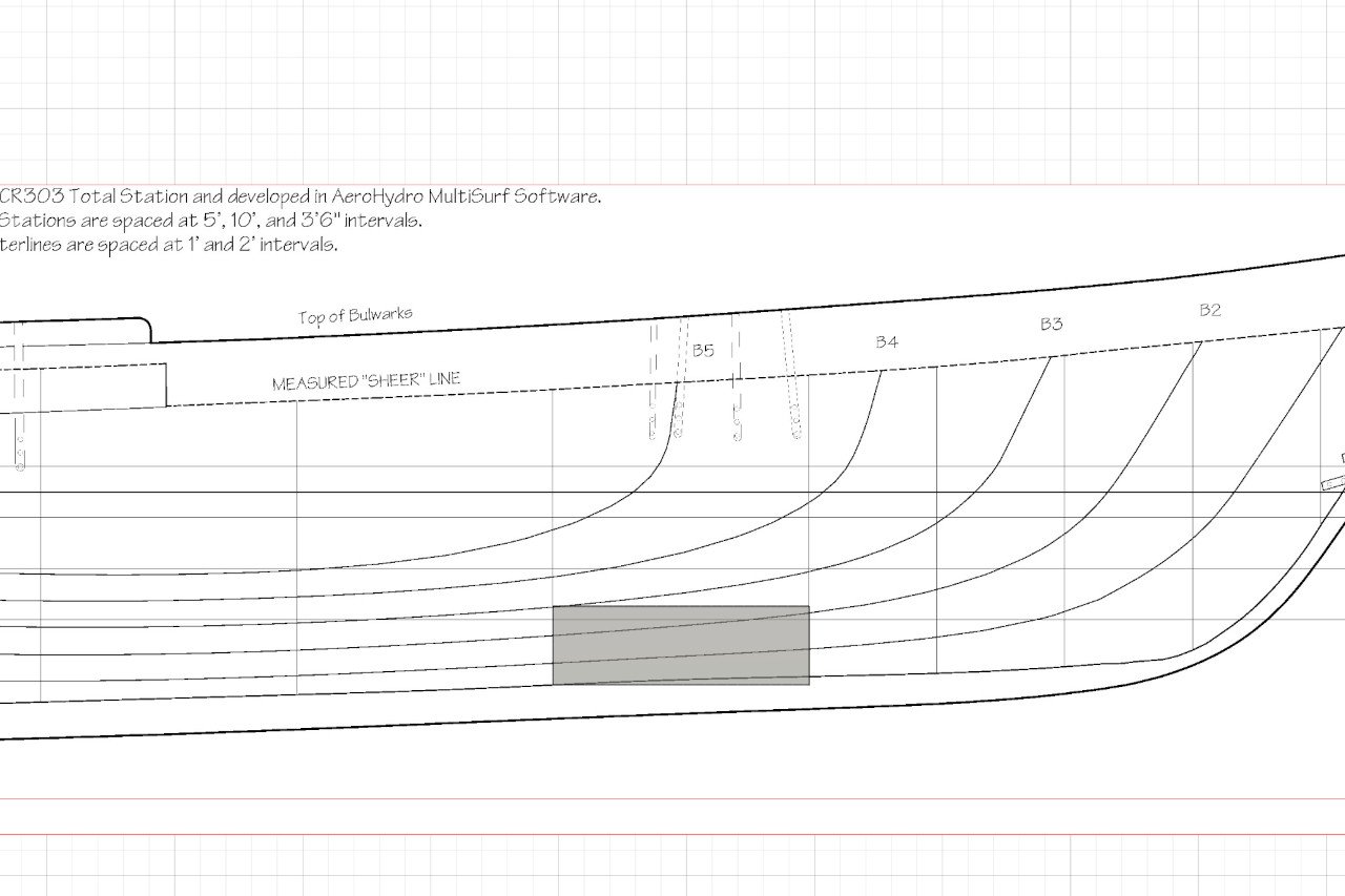
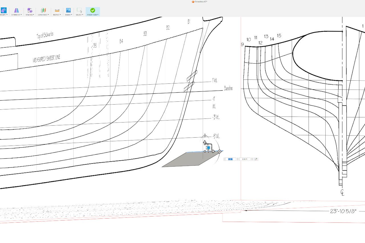
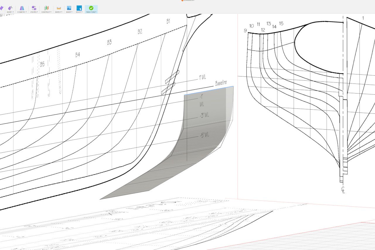
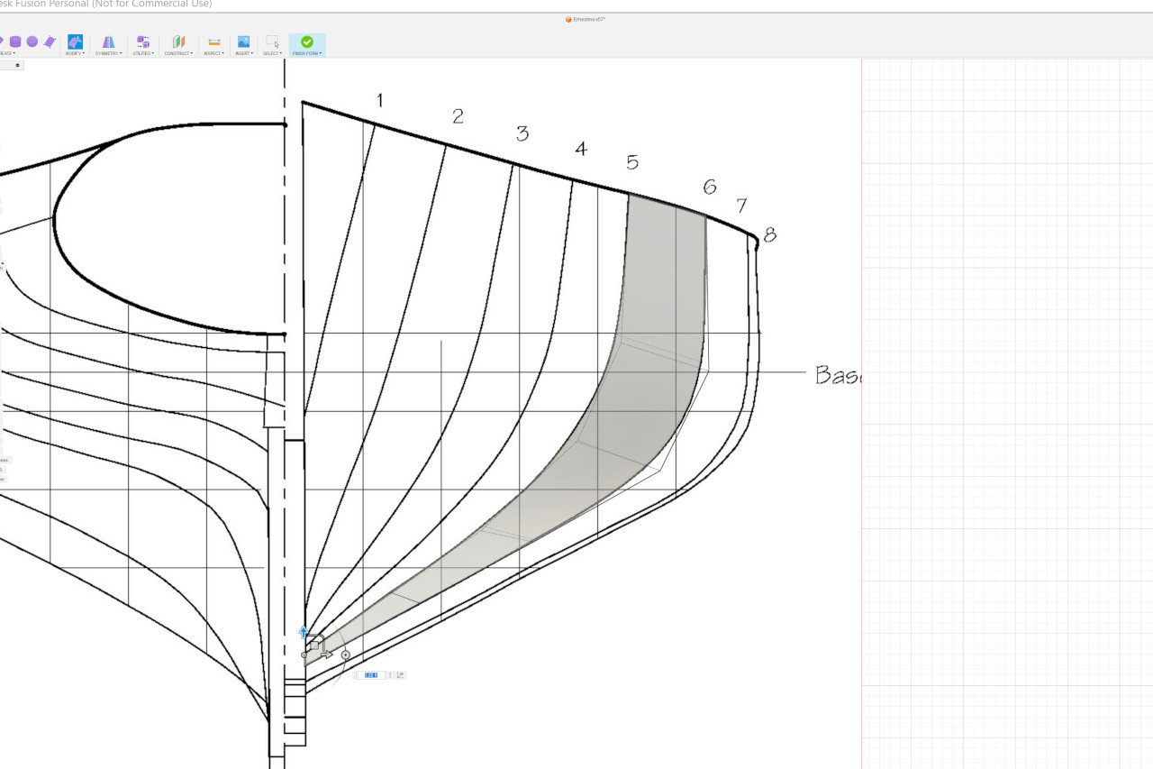
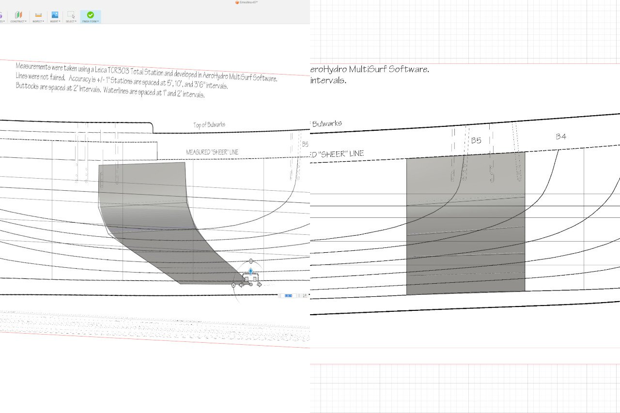
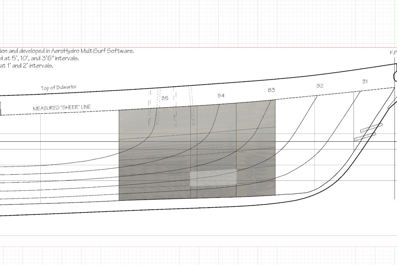
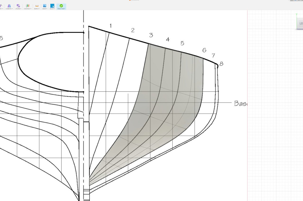
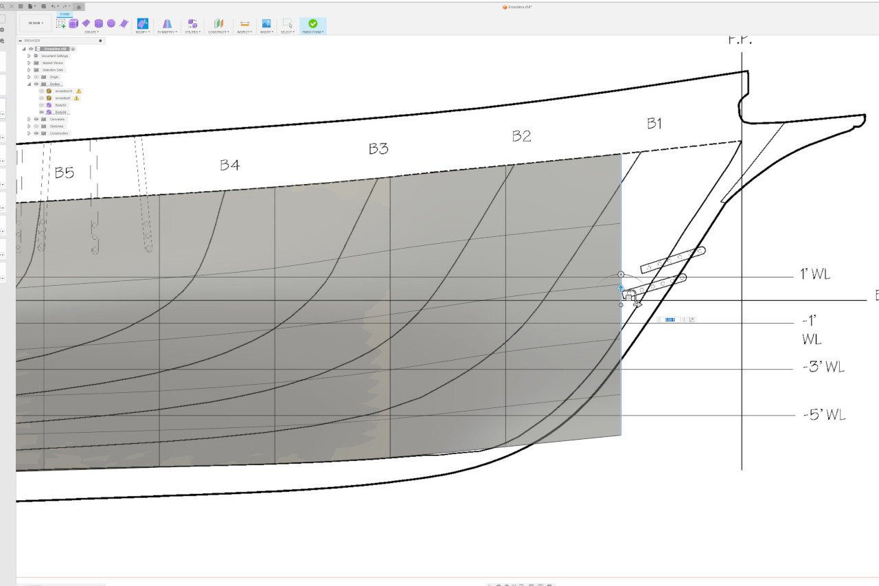
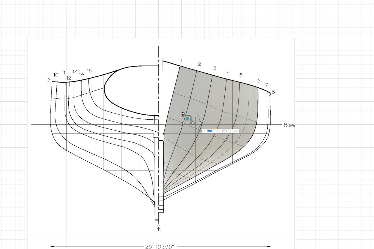
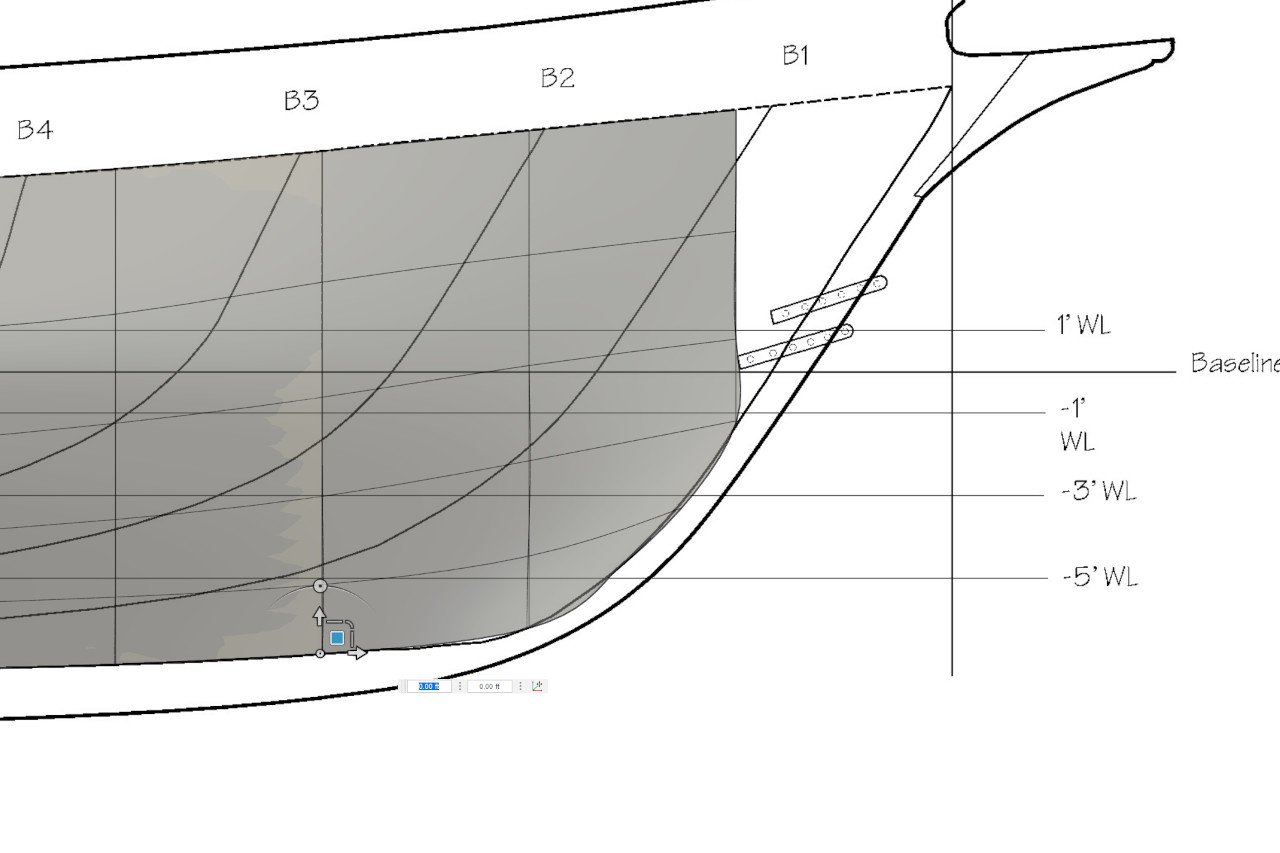
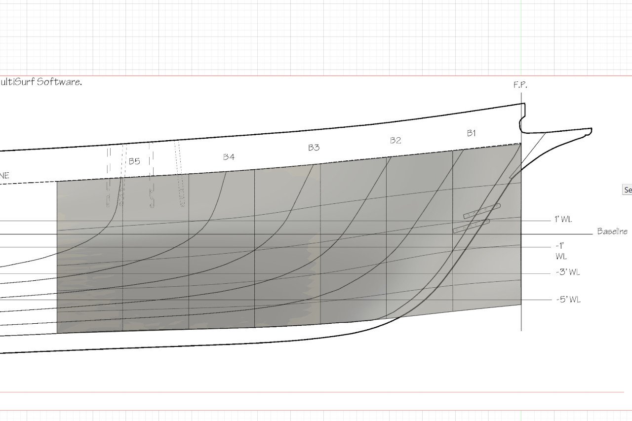
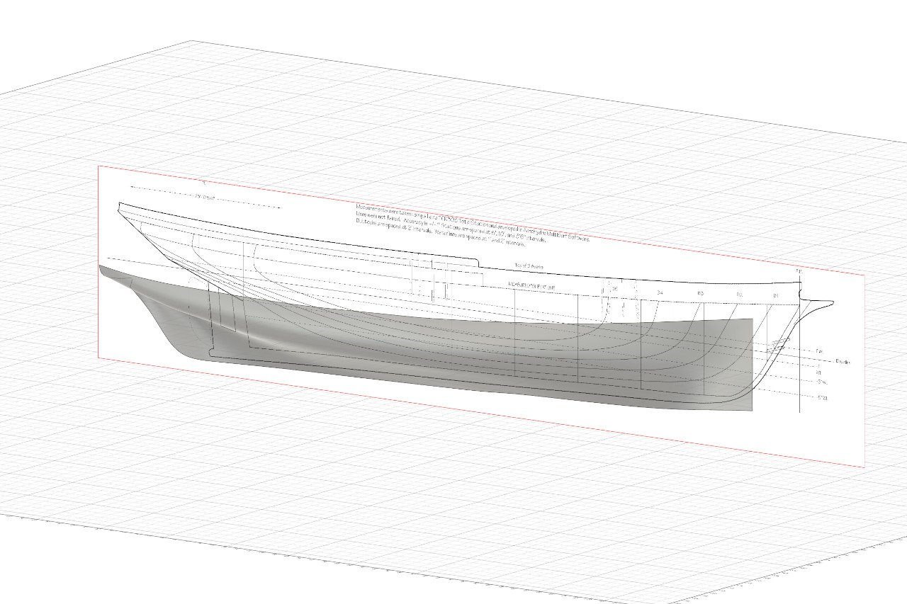
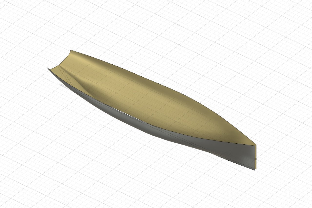
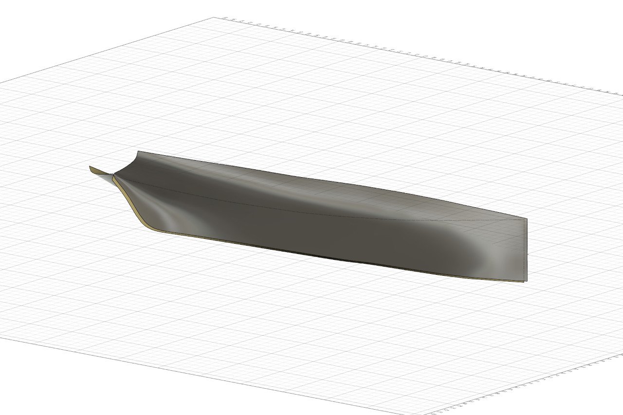
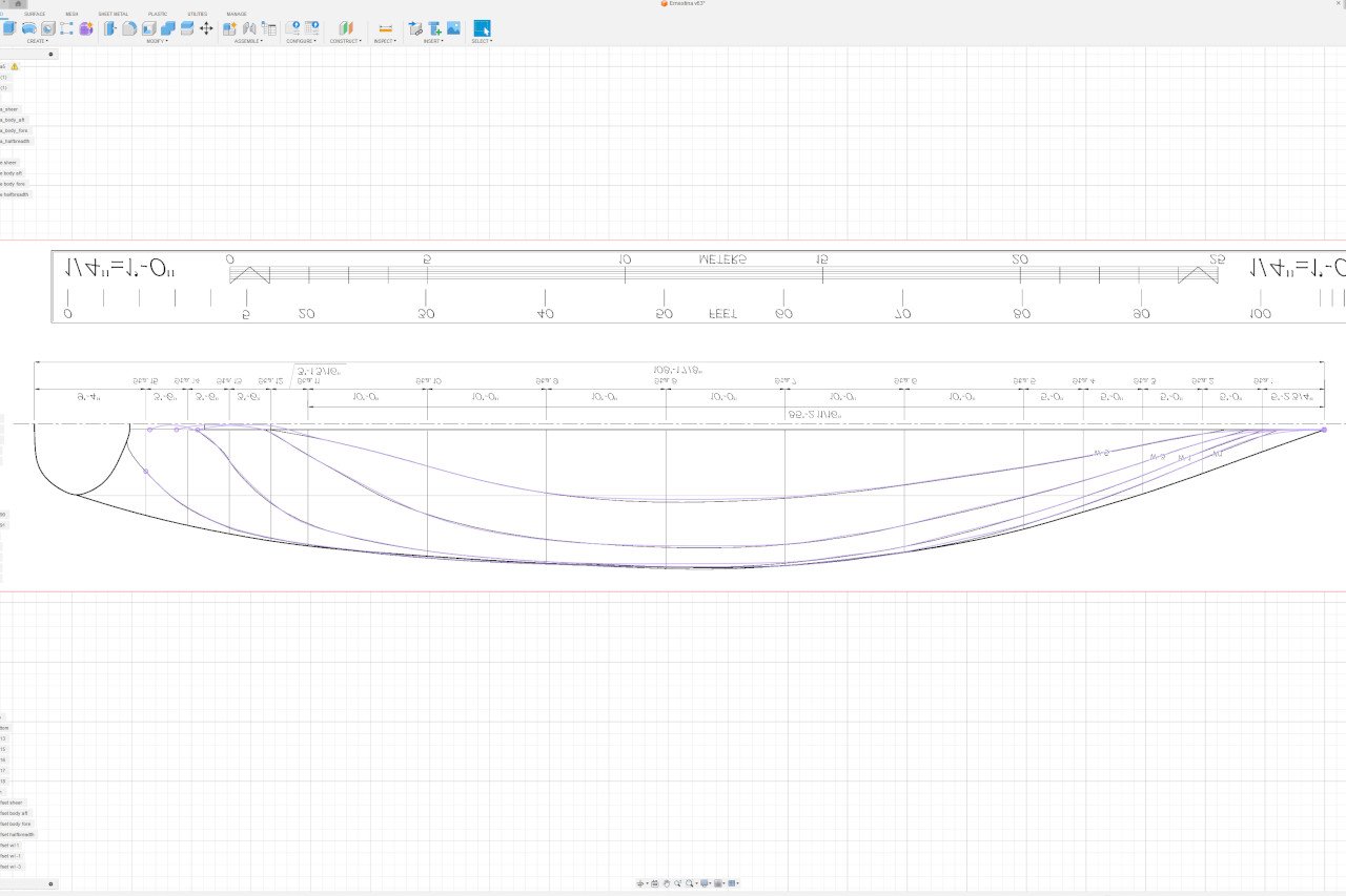
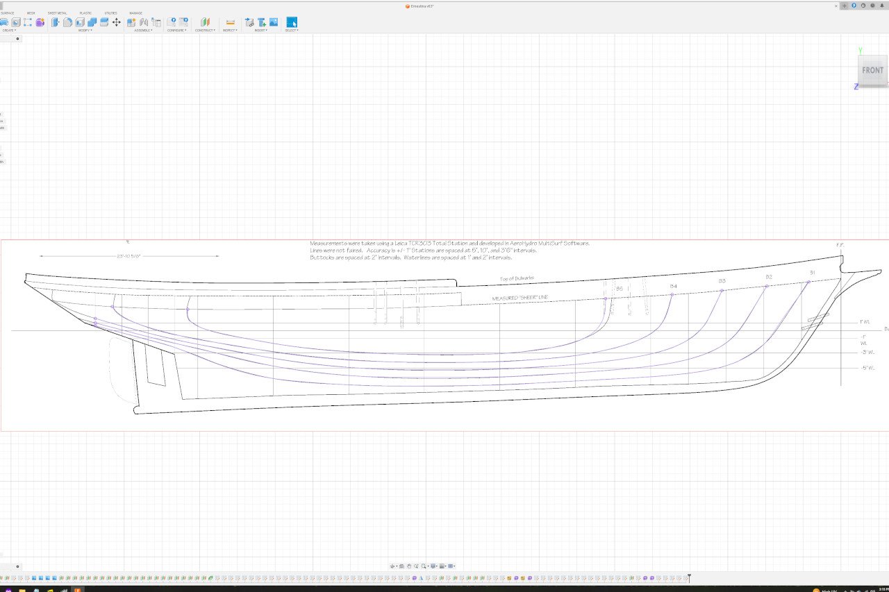
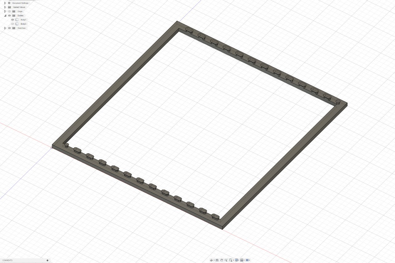
I finally got around to experimenting with Fusion's form environment. Here's a log of a method that gave me decent results. (At least, decent enough to get a form that I can slice at will to make patterns for a plank-on-bulkhead model. As you'll see, it doesn't give me a clean form for 3d printing or rendering a picture. But making bulkheads is my goal.) I start by going into form mode, and creating a simple rectangle. I grab the upper edge and lean it out a bit. Then, holding Alt as I drag I extrude a few more rectangles. Here you can see how things exist in the forms / t-spline environment. There is a grid of control points (black lines) which control the smooth form (in gray). In the Y-Z view, I adjust the curve of the edges to that they match up with the correct station lines. Fusion allows this to be done either by moving the control points or by dragging points on the curve itself. I found dragging the points on the curve to be much easier. Here is the hull section viewed at an angle and from the side. To continue, I extruded (added another row or column of control grid points) in the direction of the bow. I adjusted the curve of the new edge to the station. And then another. Working my way toward the bow. At this point, I tried to match the edge to the stem, but things started getting wobbly and I lost my clean vertical lines, which I need to match each station. There must be a way to cleanly end forms, but for now, it eludes me. So instead I just kept extending the form forward as it was. The process going aft was basically the same. (I forgot to take screenshots. Oops.) Near the rudder I did curve things in a little. The form was completed and mirrored. It looks pretty clean. The true test is to see how it holds up if I derive lines from it. I created new lines by plotting the intersection of the waterline planes and buttock line planes with the new surface. The results look good. The only significant deviation I see is the forward end of buttock line 5. As always, there is more and more to learn. If you read this far, I hope it was interesting.
-
Mark, I've been looking at the last few pictures in your last update, and I fear that the shortening that you've done at the stern will cause some issues. To my eyes, it looks like the transom and sternpost are too close together and this won't allow enough room for the rudder stock to come up between them.
-
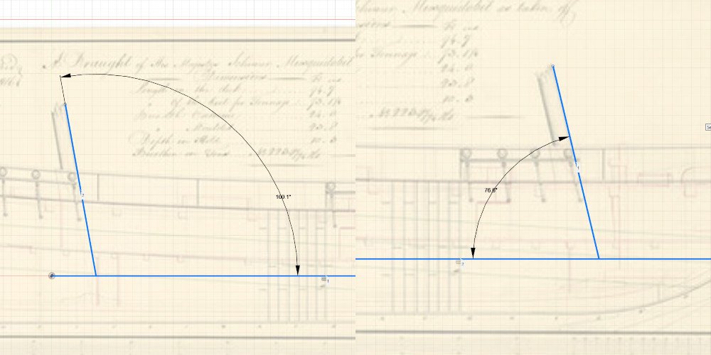
I grabbed the low res image of the plans from https://prints.rmg.co.uk/products/lines-plan-of-musquidobit-1813-j7636 Brought them into Fusion, and made a quick measure of the angles. I get 13.4 degrees for the foremast and 10.1 degrees for the mainmast. These might be off by a few tenths of a degree since I was just eyeballing my drafting lines in Fusion. I've done this for a few other schooners, and the masts are never parallel. There is always some difference in the angles of the rake.
-
I've been looking forward to it since you mentioned you'd be working on this one. I'll be following along.
-
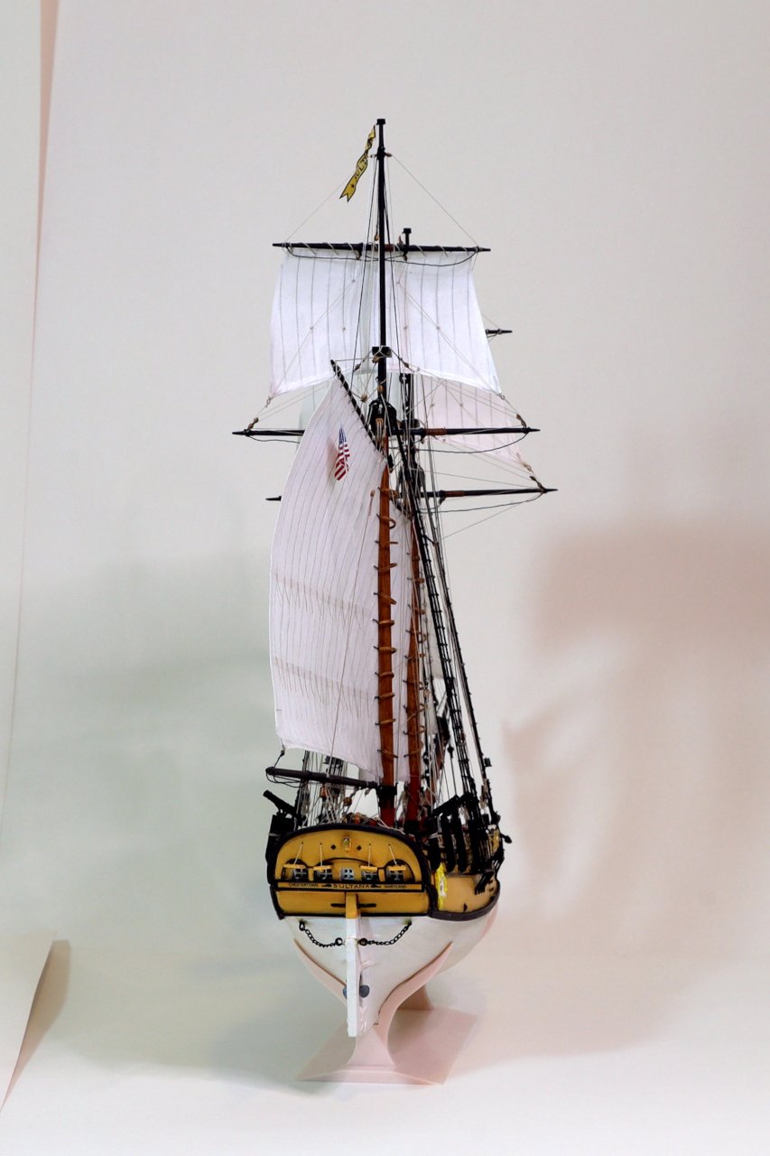
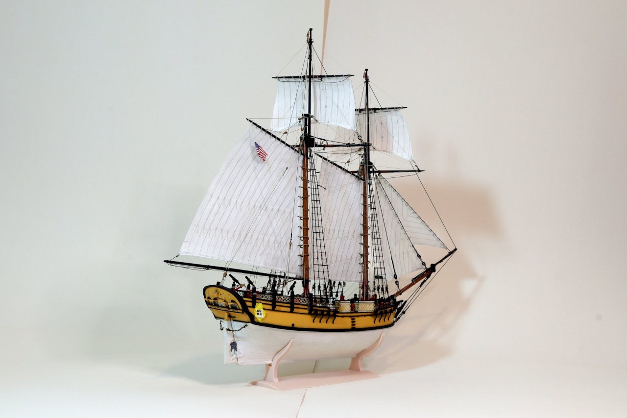
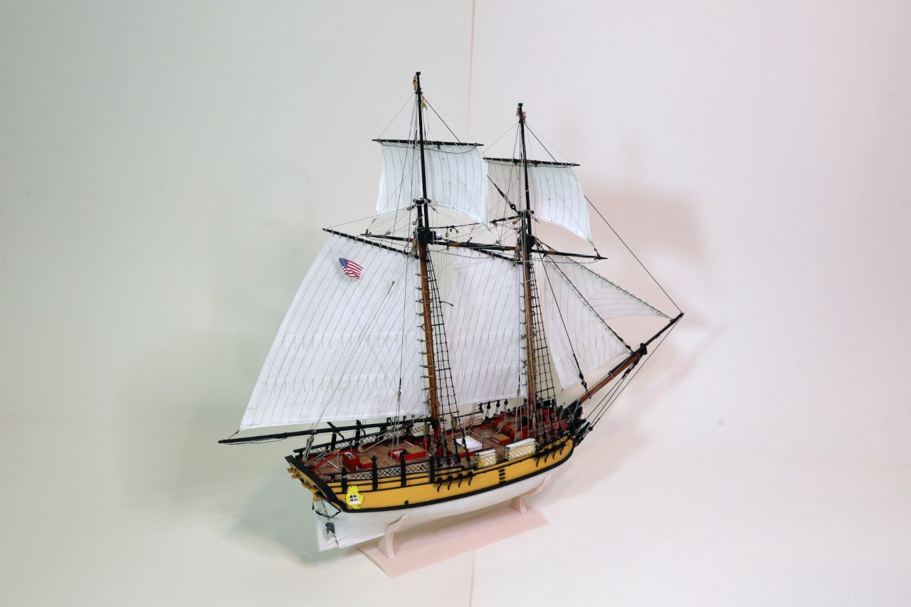
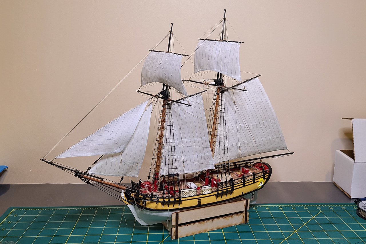
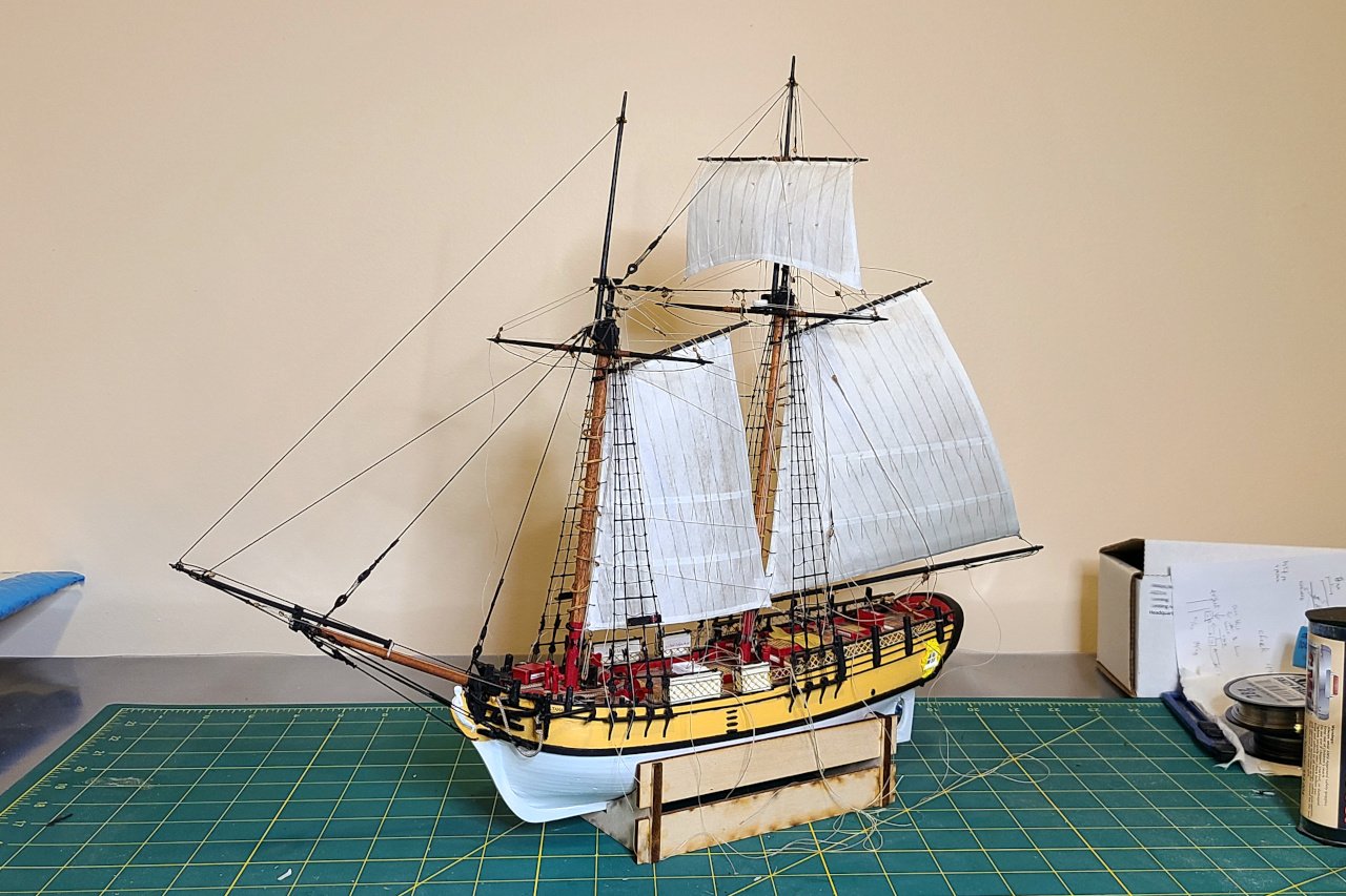
Having reached the end, it's hard to know what to write. This has been a build like no other, and one where I created a lot of challenges for myself. The main goal was to expand my modeling experience and to try out some unconventional techniques. That goal, I think, was achieved. If I could go back in time and give myself advice, I would have recommended making this a fully scratch build and executing it in 1:48 scale (or even 1:32). I have read that when Model Shipways releases a new POB Sultana, it will be in 1:48 scale, and I can understand why. Working at 1:64 has been the biggest challenge, and many times I wished I didn't have to work with such small blocks and other components. I'm also disappointed by the sloppiness of some of my work, especially the painting, and the lack of crisp details on some of the components that I made. (And that big glob of dried glue, that I've been strategically hiding when I take pictures.) I still have lots of room for improvement. Thank you to everyone who has been following along with this build. Your comments and encouragement have been much appreciated. I hope to see you when I start my next one. Moderators, if you are reading this, please mark this build log FINISHED.

- 222 replies
-
- 10
-

-

-
- sultana
- model shipways
- (and 1 more)
-
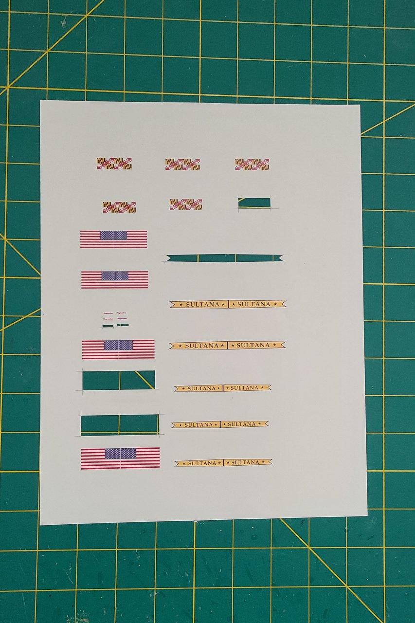
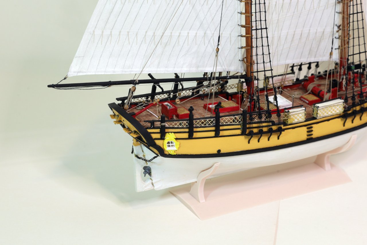
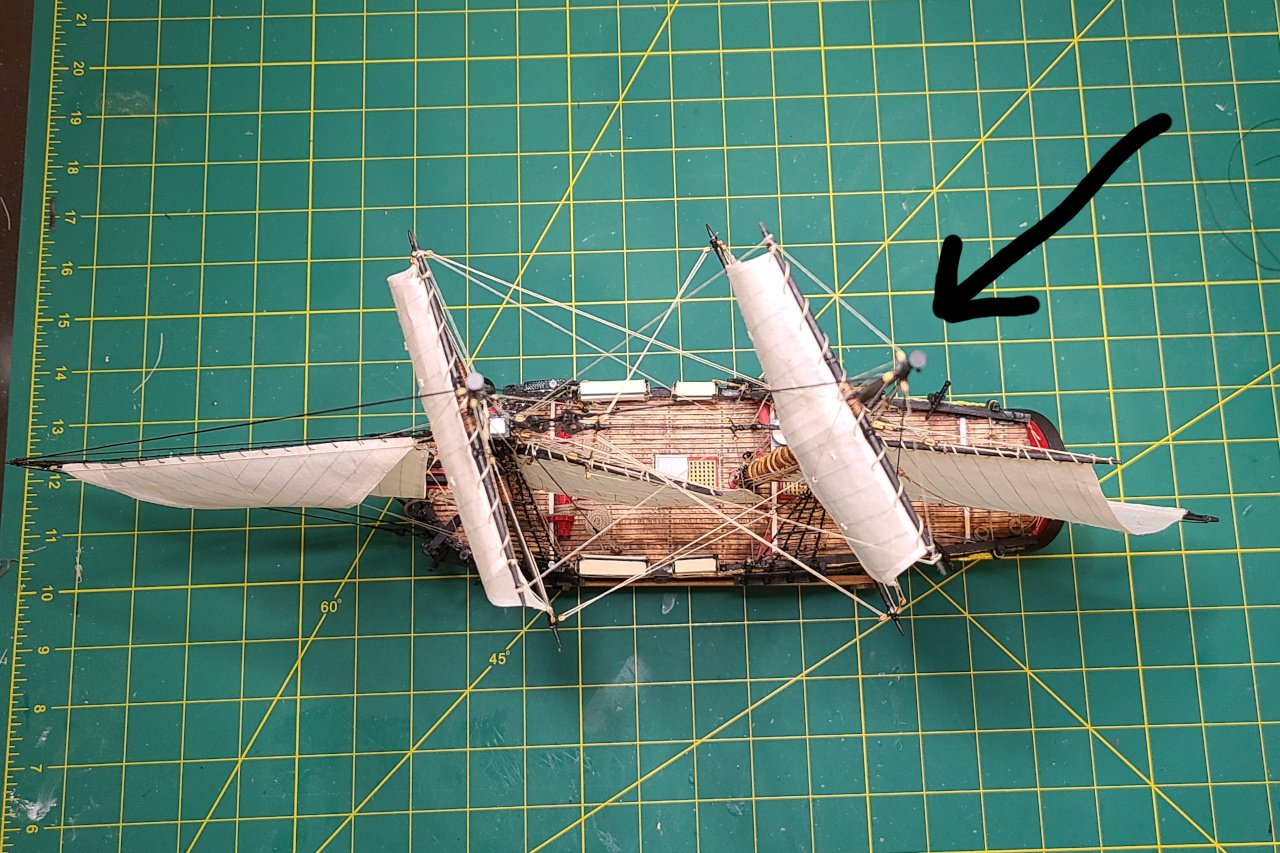
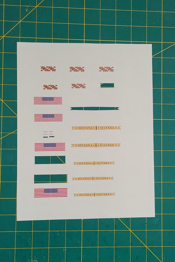
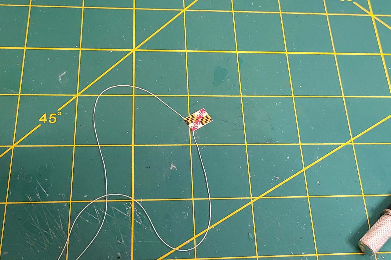
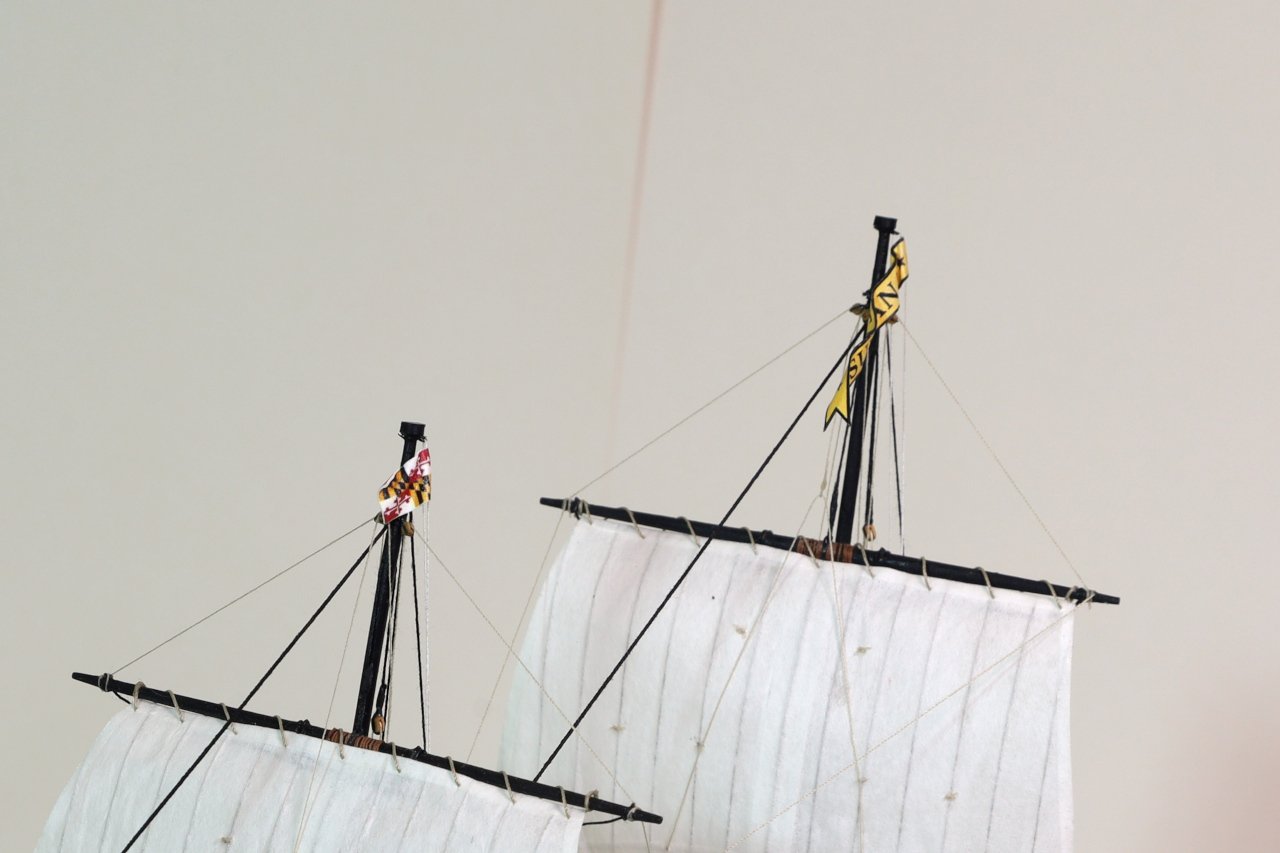
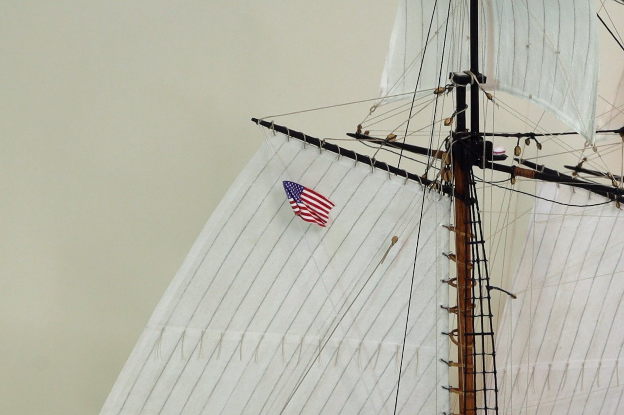
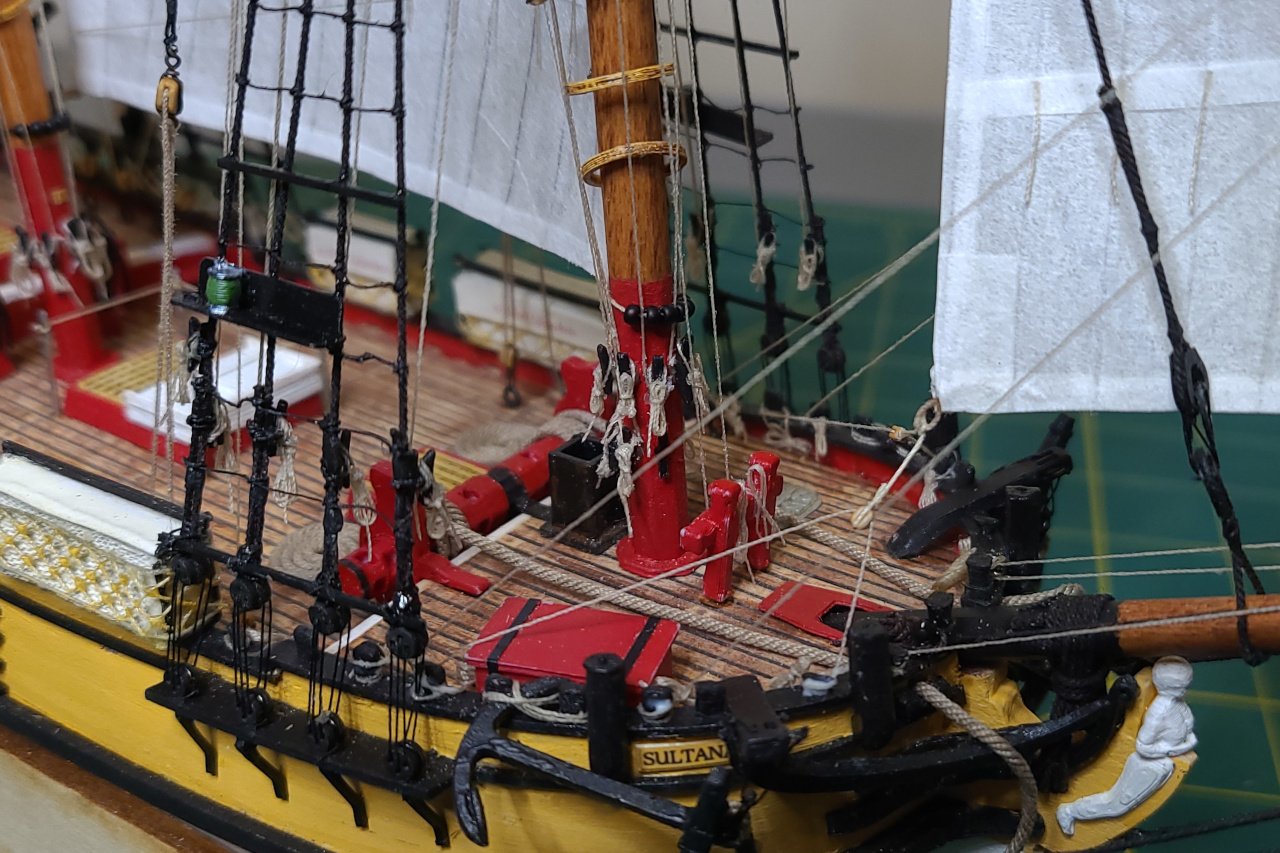
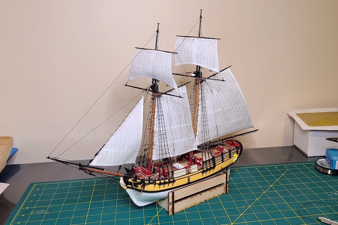
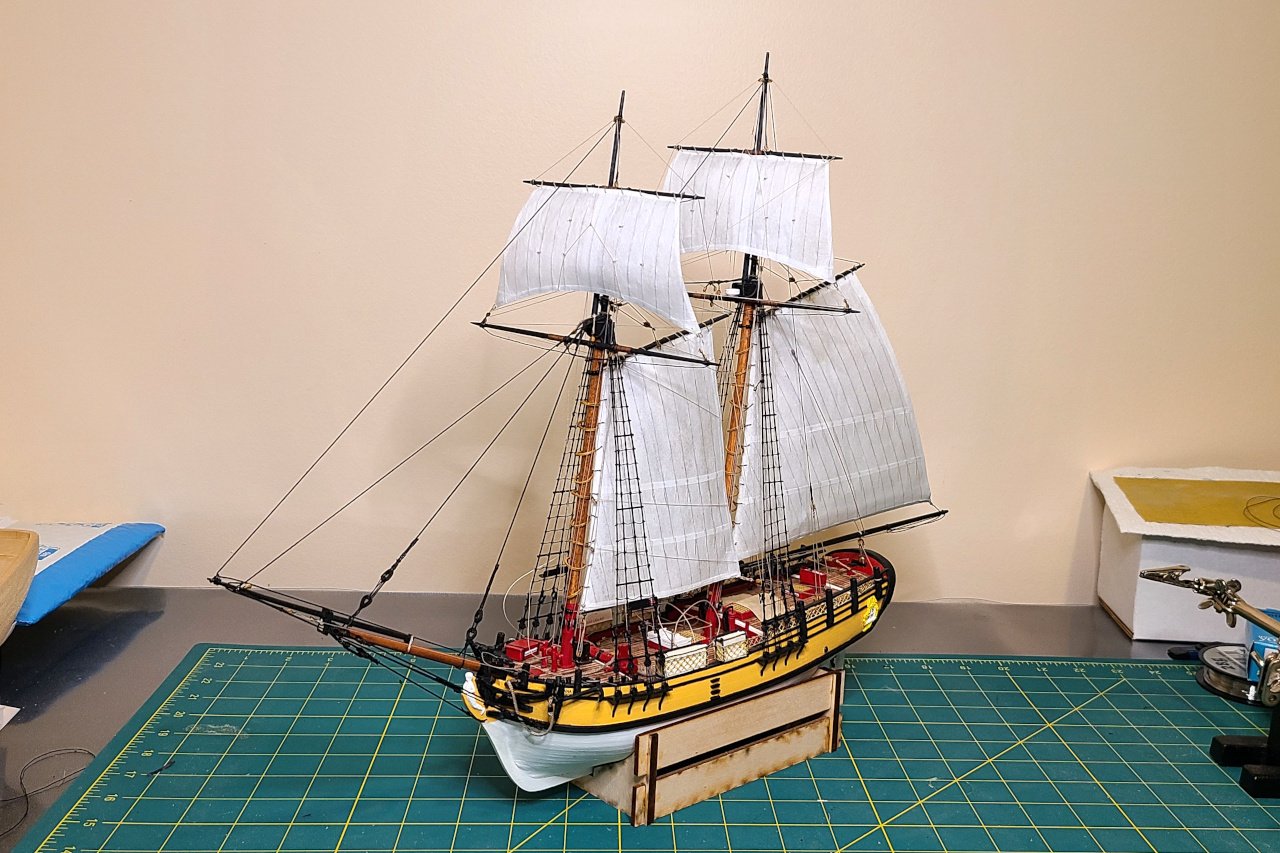
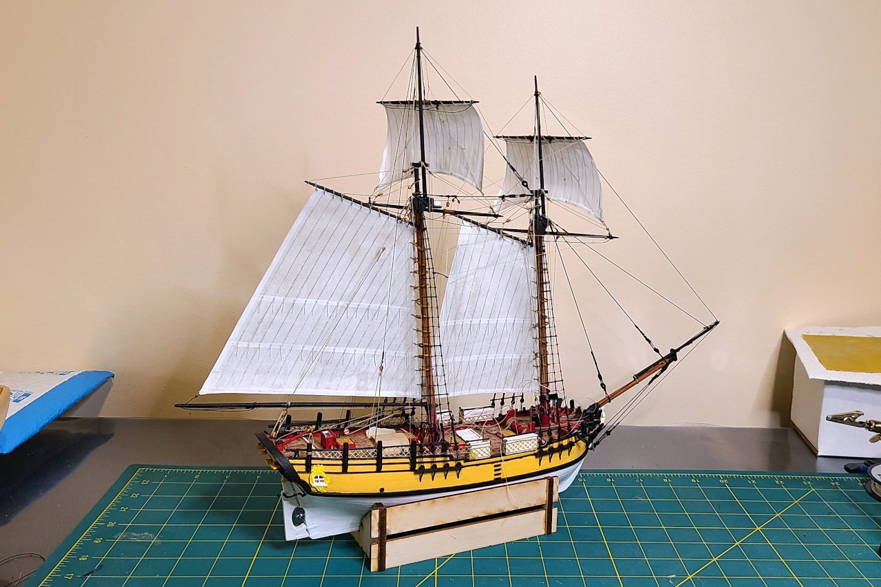
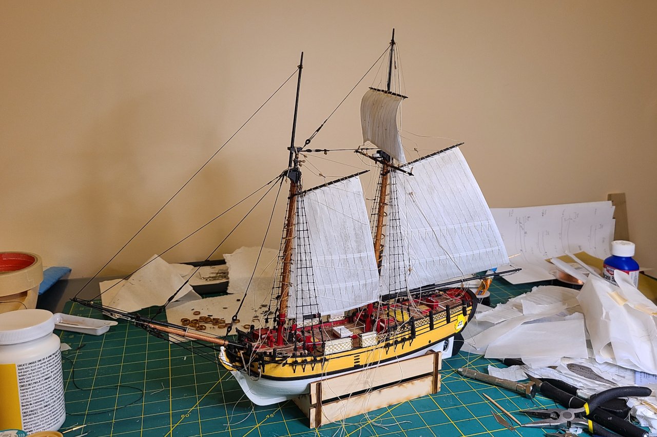
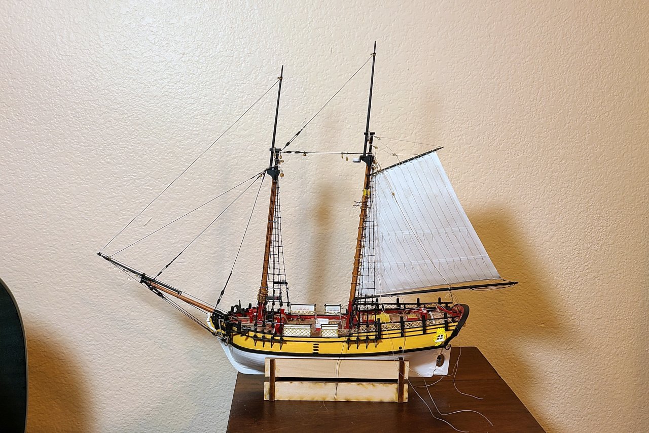
With flags, the most important thing to consider is the wind direction. I have been working with the idea of the wind coming from the direction as shown below. I think this is plausible with the sails in the orientation they have been set to. I worked out the flags and their sizes and created a sheet for them. Multiple copies were added to allow for mistakes and to try a few variations in size. It was printed out at the local shop. The colors a good, but the paper is a bit thicker than I would have liked. The flags were carefully cut out and glued onto thread, then formed by wrapping the paper around a toothpick until the curves looked good. The flags on the masts, showing the wind coming from behind, but not too strong. And this one back here gets blown into the mail sail. TODO: Tie down jib sheets DONE Make a zillion rope coils (it was closer to 60) DONE Glue on a zillion rope coils DONE Swivel guns DONE Flags DONE Ship's boat? I've decided that this will be a separate project, to be completed at a later date FINISHED We'll save crossing off number 7 until next time, where I'll reflect on this project and include a bunch of beauty shots.
- 222 replies
-
- 2
-
-
-
- sultana
- model shipways
- (and 1 more)
-
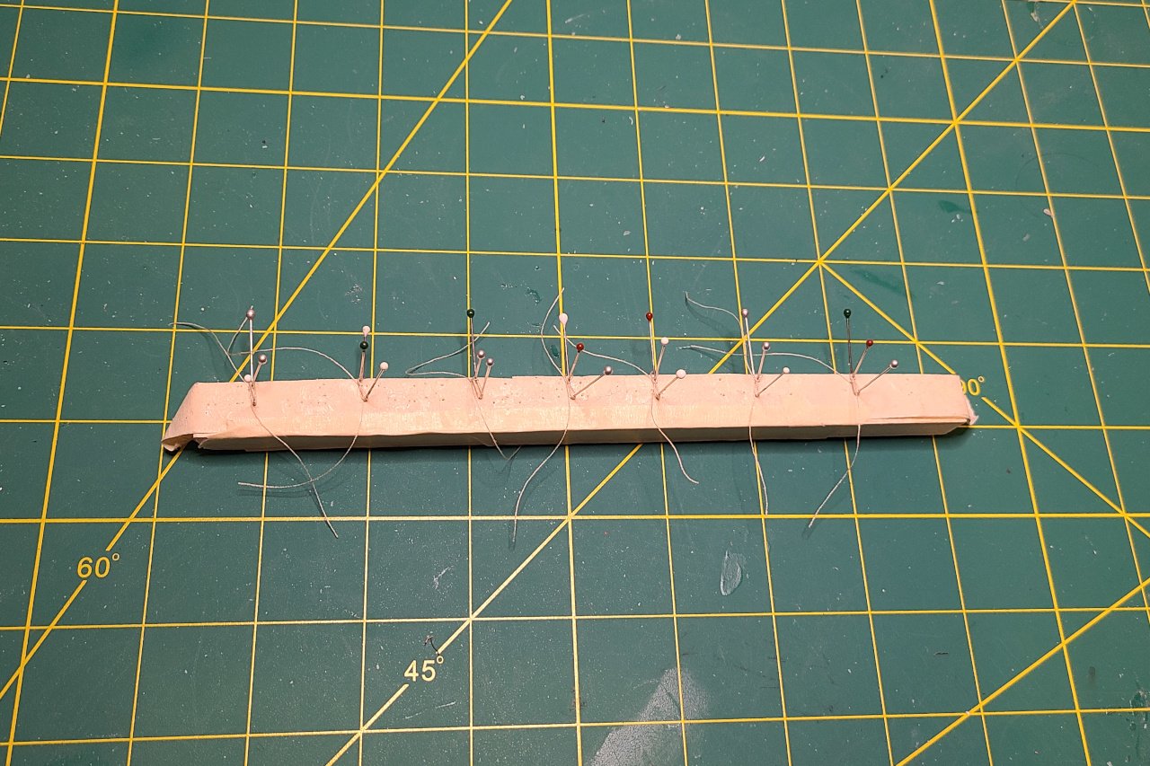
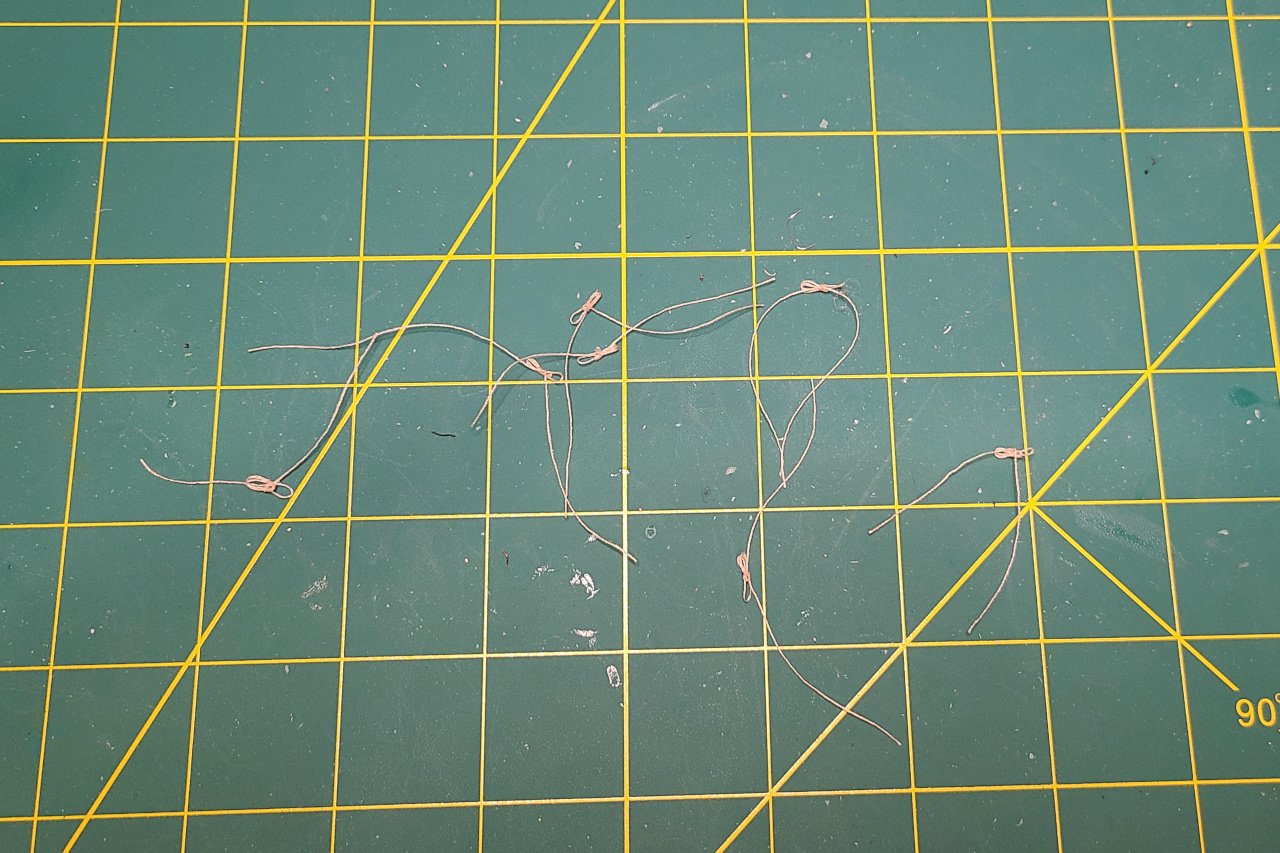
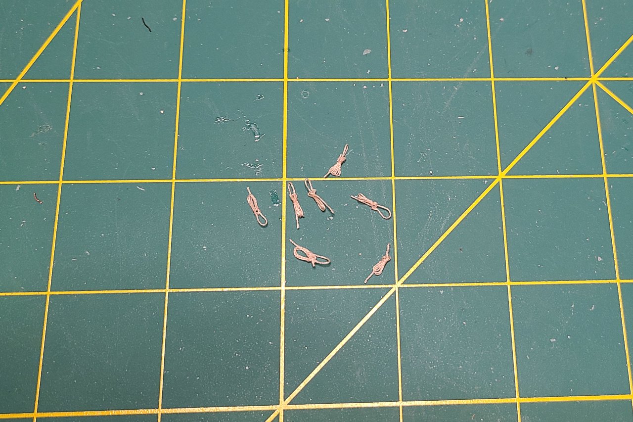
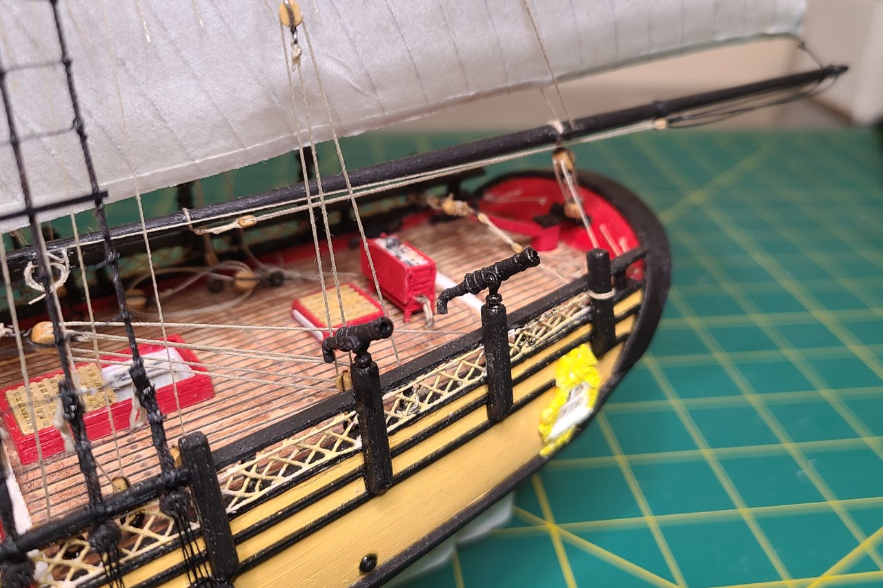
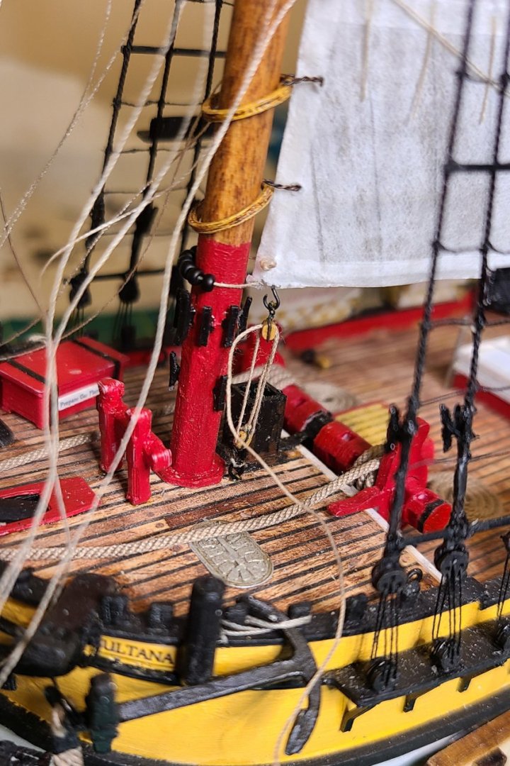
Making rope coils. After some experimentation, I ended up wrapping thread around some pins stuck into a scrap strip of balsa. They were strategically glued, and after the glue dried, the pins were removed and the rope coils were pulled off. And the excess thread was cut away. Here are some rope coils on the fore mast. And on the shroud cleats I tried making my own swivel guns, but I wasn't happy with any of them, so I used the kit-supplied guns. The barrels were drilled out, but they were otherwise unmodified. TODO: Tie down jib sheets DONE Make a zillion rope coils (it was closer to 60) DONE Glue on a zillion rope coils DONE Swivel guns DONE Flags Ship's boat? FINISHED

- 222 replies
-
- 2
-
-
-
- sultana
- model shipways
- (and 1 more)
-
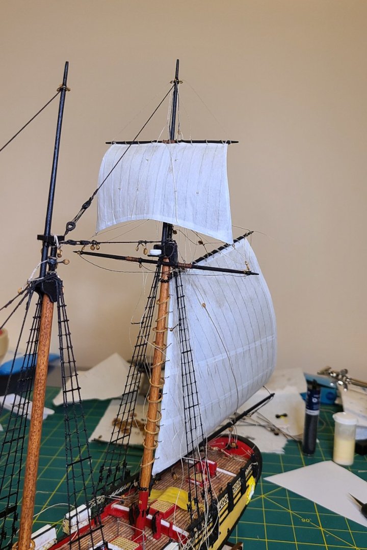
Sail 6 of 6 is on. TODO: Tie down jib sheets Make a zillion rope coils Glue on a zillion rope coils Swivel guns Flags Ship's boat? FINISHED
- 222 replies
-
- 4
-
-
- sultana
- model shipways
- (and 1 more)
-
I think it'll be a 19th century Chesapeake Bay craft, but I'm still in the research phase.
-
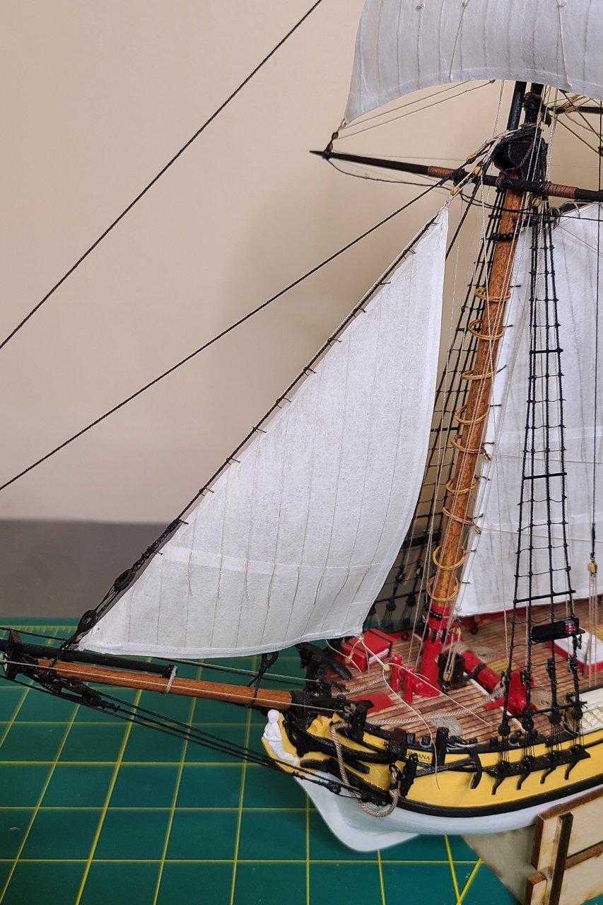
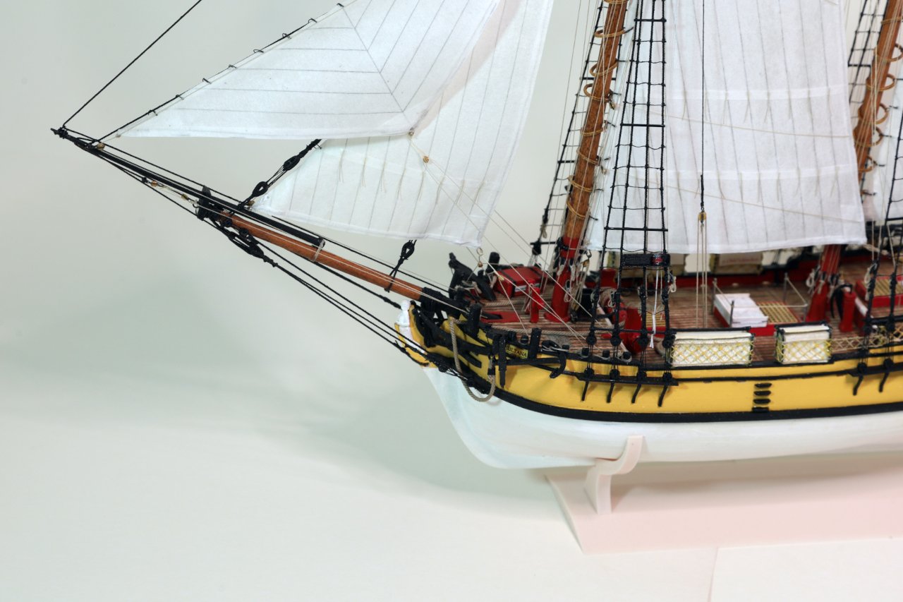
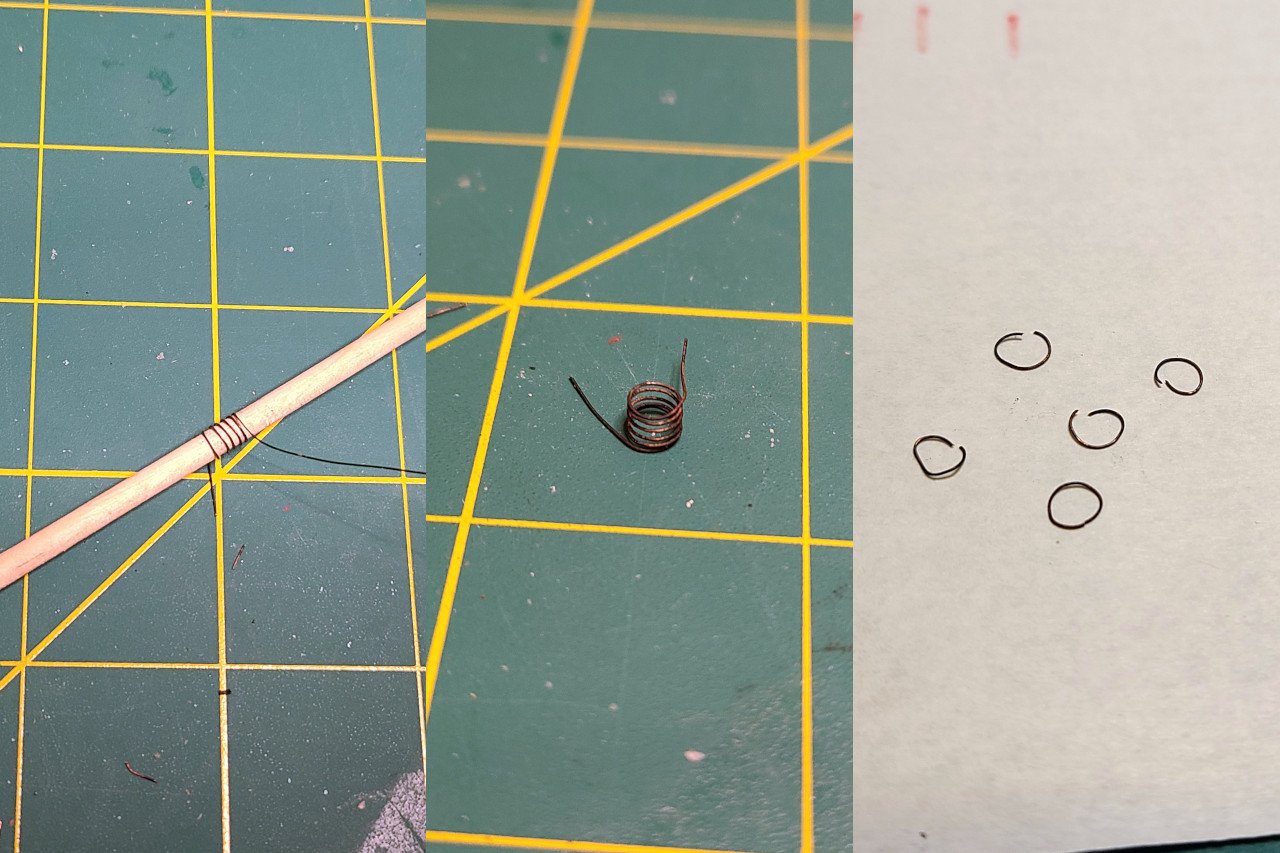
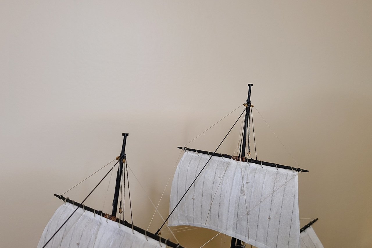
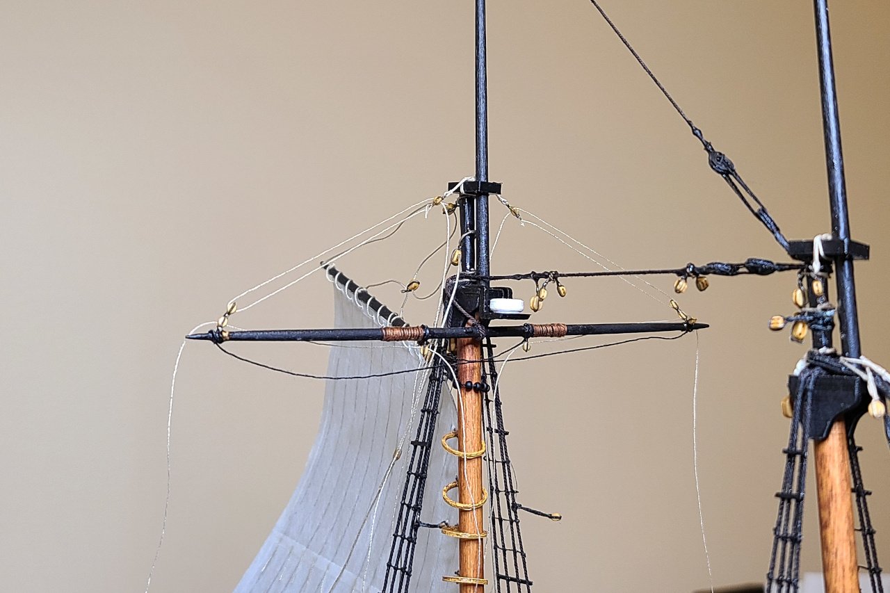
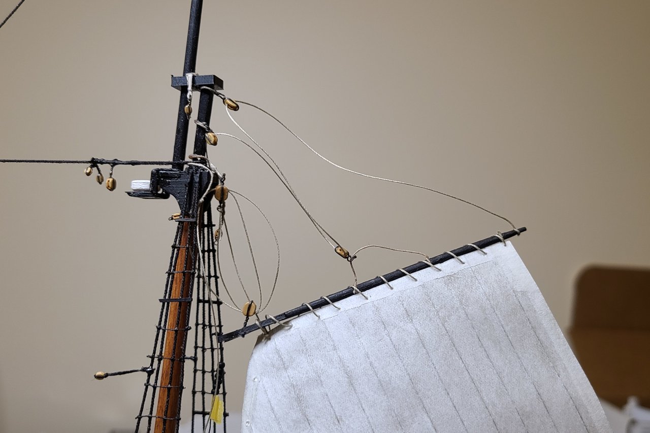
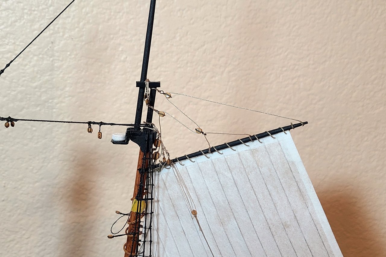
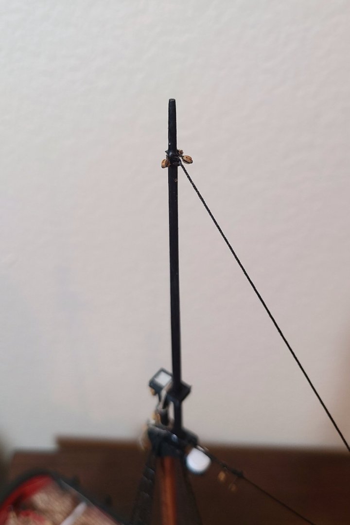
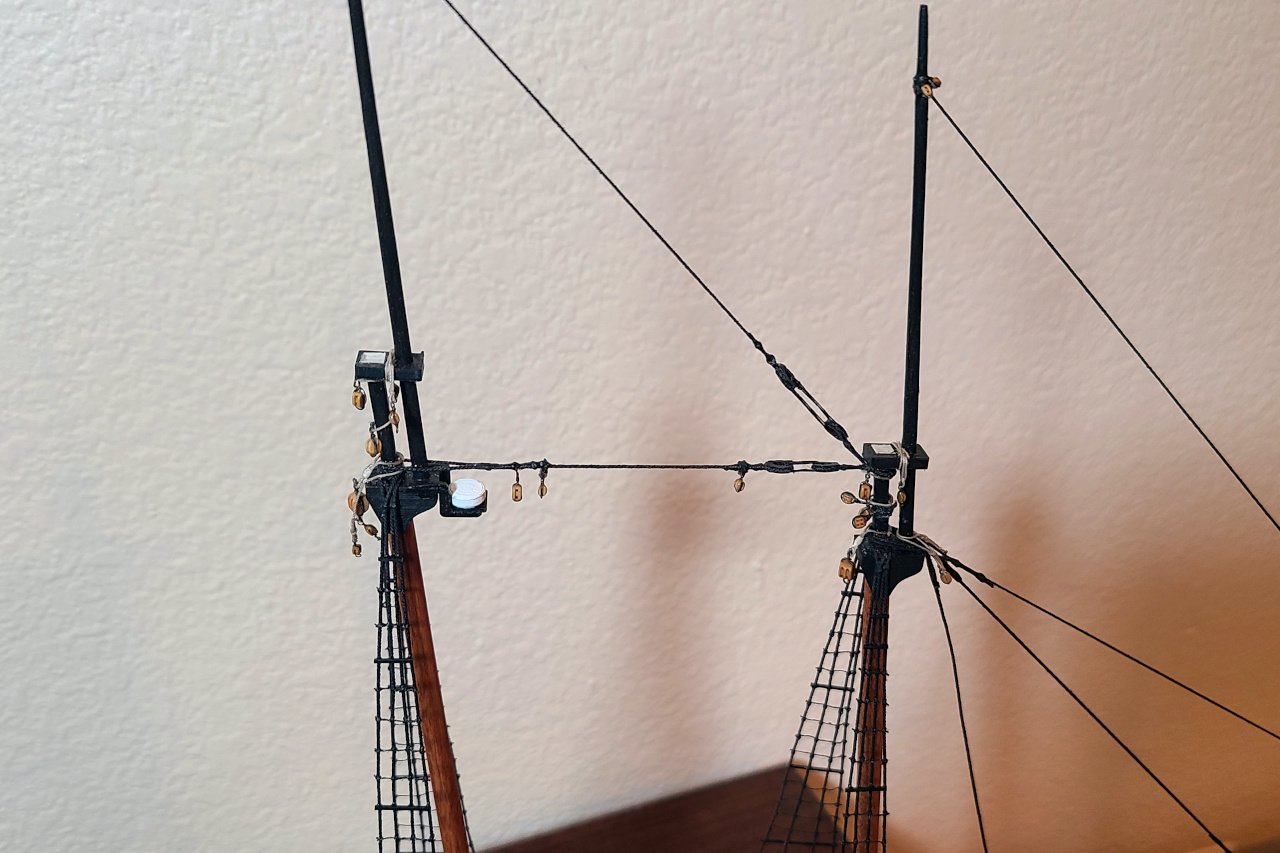
To attach the jib sails, I made hanks as shown below by wrapping blackened wire around a dowel, resulting in a spring, then cutting the spring into individual loops. Here's the inner jib. The line at the top is for the downhaul. Note how a pair of blocks splits the sheets into four separate lines. And here is the sail in place. The backstays for the foremast were also on the todo list. If you look back at post #173 in this thread, you'll see how I tied off some line on cleats in preparation for this step. I anticipated that those cleats would be completely inaccessible and it's a good thing. The mast trucks were 3D printed. Development was interative, Goldilocks style: too large, too small, just right. Here are the mast trucks after being glued on. It really makes things look finished. Looking good and almost done.


- 222 replies
-
- 4
-
-
-
- sultana
- model shipways
- (and 1 more)
-
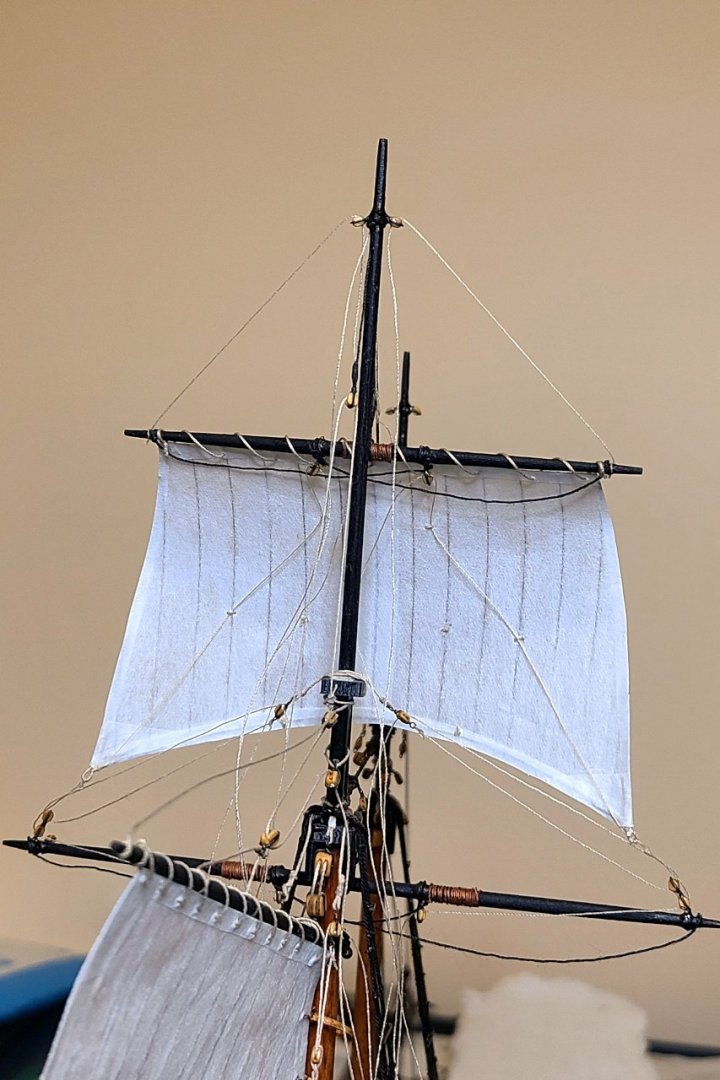
The fore topsail is on. And here's a view from the back. And a view from the top. It's quite a maze. Two more sails to go, plus the many finishing details.
- 222 replies
-
- 6
-
-
- sultana
- model shipways
- (and 1 more)
-
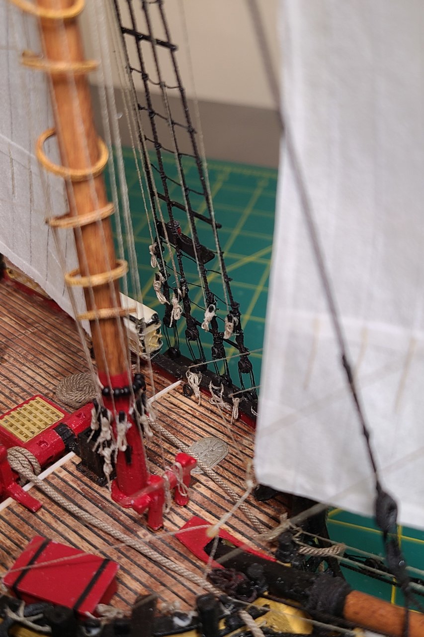
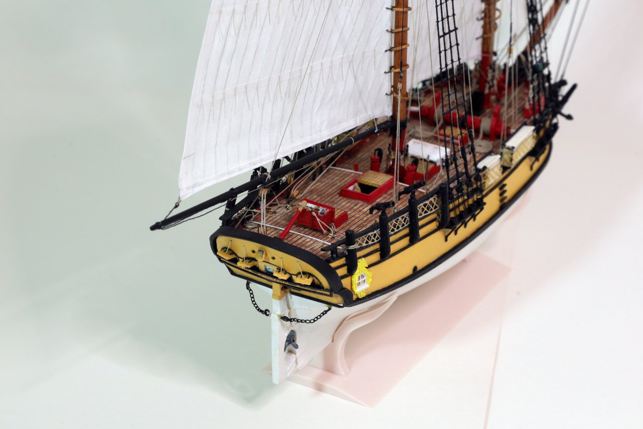
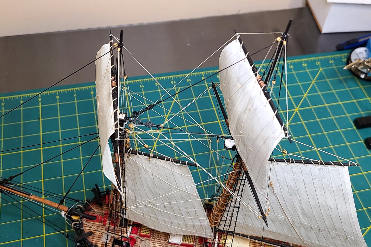
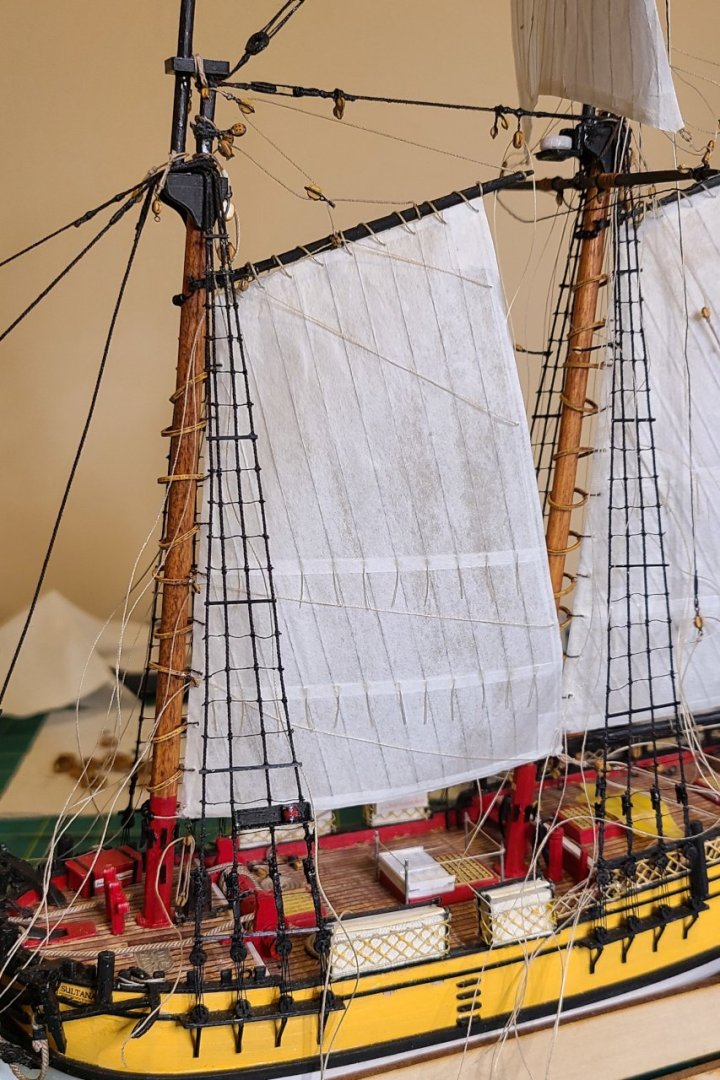
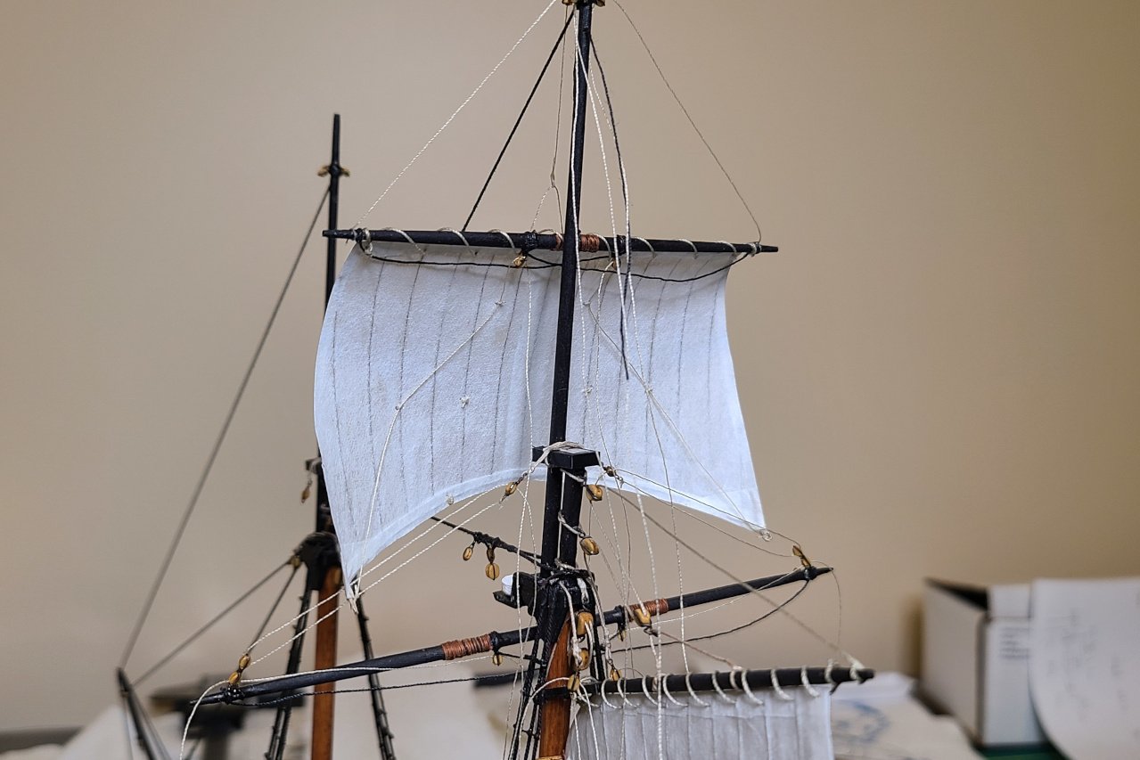
A small update. Lots of lines that were loose have been belayed and glued. It doesn't look like much of a change between this update and the last, but I spent several hours tugging and adjusting until I was happy. I hung the fore lower yard from its sling and threaded the lifts and braces. The mainsail still has some lines that need final adjusting before it's permanently set. Another thing I did was redo the forestay, which had accumulated some noticeable slack. I've been unhappy about that for a while.
- 222 replies
-
- 4
-
-
-
- sultana
- model shipways
- (and 1 more)
-
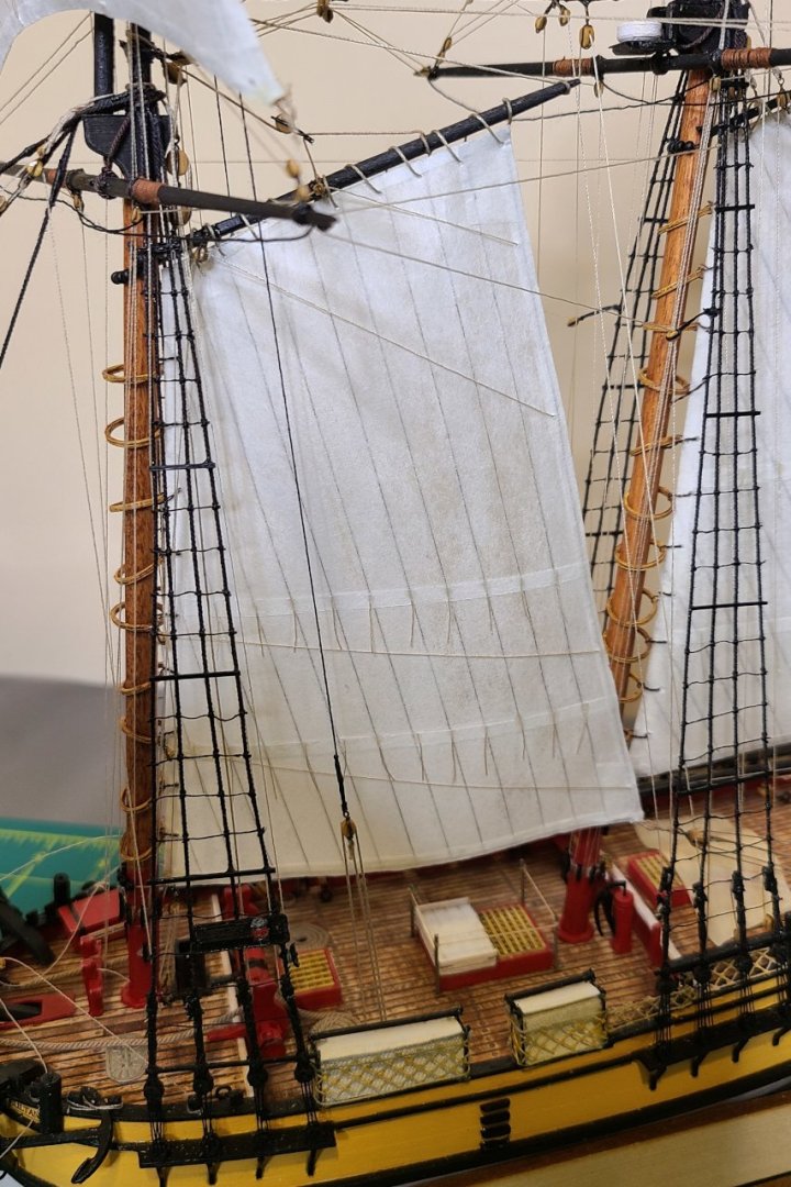
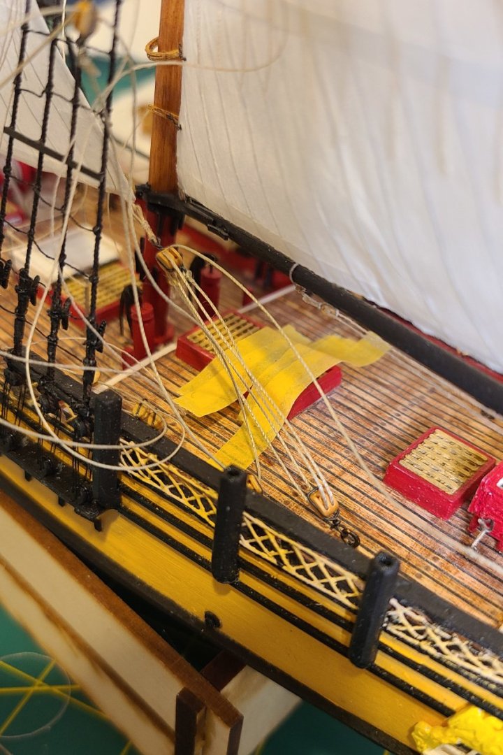
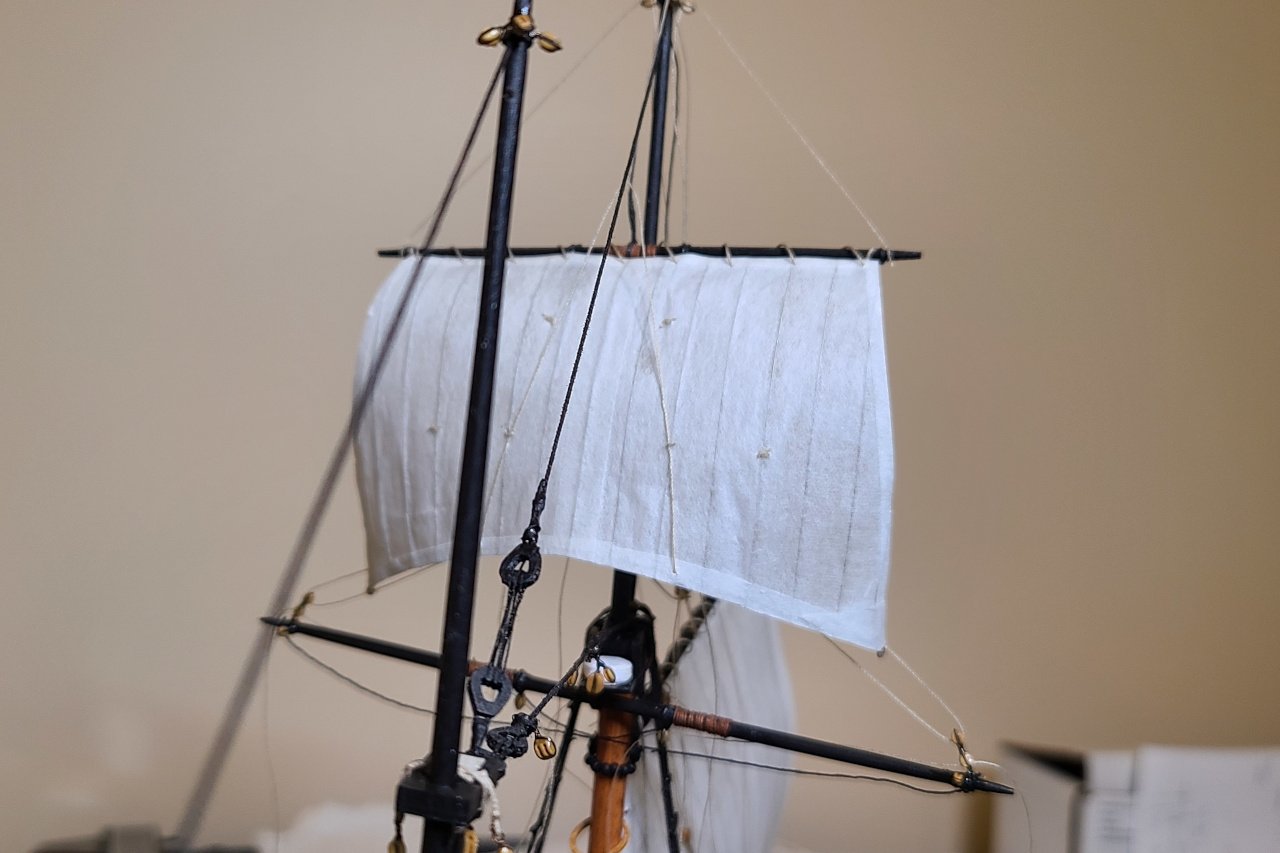
Here's the foresail. The brails that run through blocks on the gaff have been pre-threaded. The remaining brails run through blocks on the mast hoops and will need to be run after the sail is attached. And the sail is on. As with the mainsail, the sail is linked to the mast hoops with wire. There is one error here. The blocks for the third brail from the top should have been attached to the mast hoop fourth from the top, not fifth. You can see how the angle of the run of that brail doesn't match the others, but would be parallel to the others if it were in the right place. Unfortunately, when I realized this mistake, the glue was set and those were literally my last 2mm blocks. So I'll have to live with it. Down here at the tack, the sail is hooked onto a tackle that was previously threaded. The mainsail sheet runs through a pair of double blocks back here. And here it is, three sails down, three to go. Ugh, what a messy workspace. Next I need to get the spaghetti under control before moving on to the remaining sails.

- 222 replies
-
- 3
-
-
-
- sultana
- model shipways
- (and 1 more)
-
Thanks for following along, Mark. It's hard to believe it's finally all coming together.
-
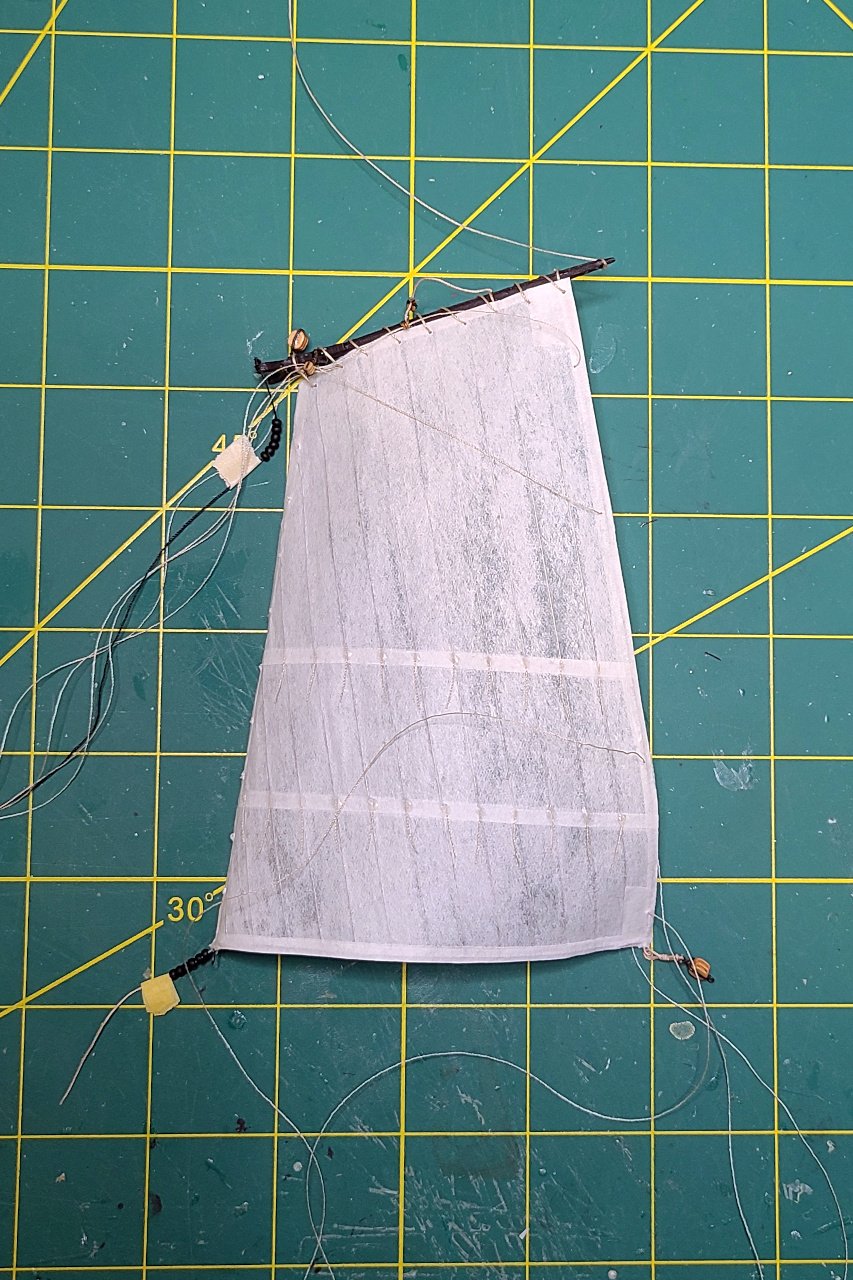
Prior to being attached to the mast, the main topsail's lower yard has its blocks pre-threaded. It is held up by its sling and lifts. Now the upper yard. The sail is laced on. The bunt lines are visible here on the front. And the clew lines are pre-threaded through the blocks on the back. Here is the upper yard, held up only by its lifts for now. The halliard is threaded through the sheave hole in the mast. But the halliard (black thread) currently goes nowhere. A block is carefully attached to the free end of the halliard and rigged. Also, the sheet lines previously threaded through blocks on the lower yard are attached to the sail. And with that, most of the rigging of the main topsail is complete. Still to do for the main mast: backstays and braces for the yards. And right now, nothing is belayed. It's all loose so that I can fiddle with how I want the sails oriented. I think the braces will wait, as I suspect they'll get in the way of my efforts to attach the foresail.
- 222 replies
-
- 4
-
-
- sultana
- model shipways
- (and 1 more)
-
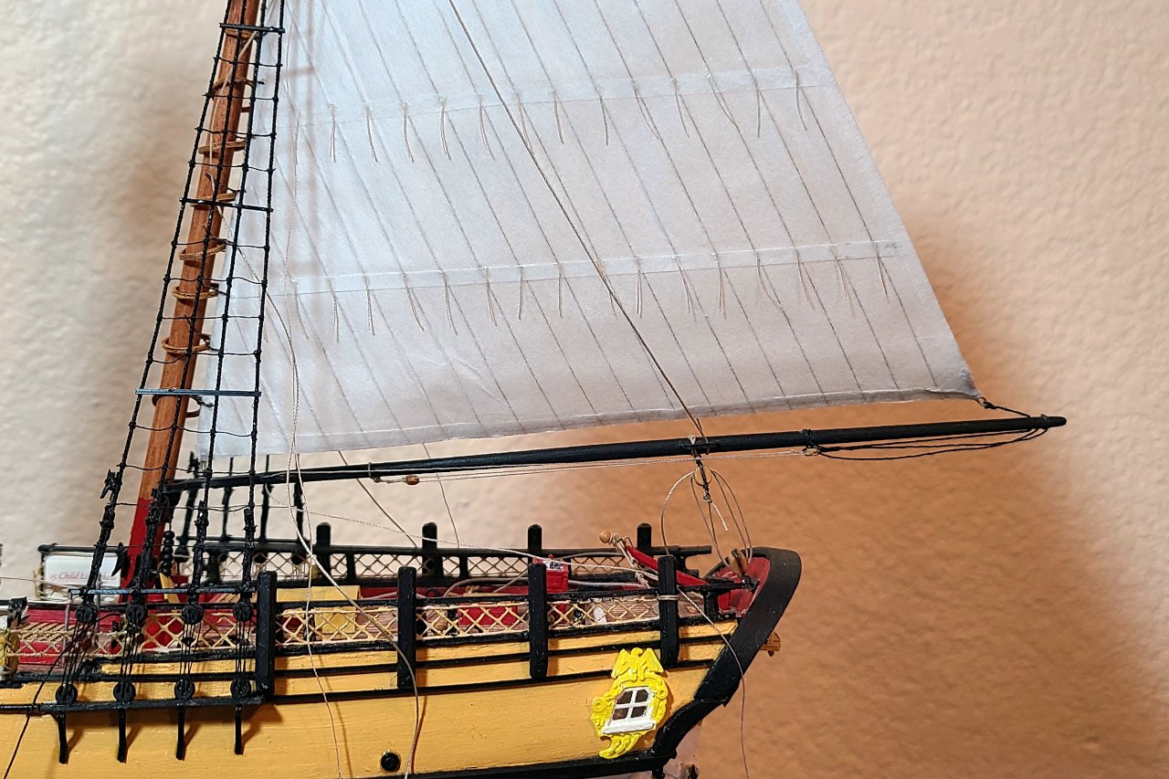
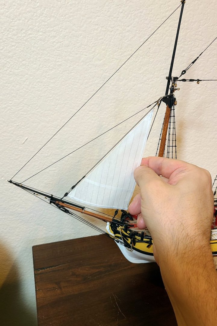
I'm starting with the mainsail. First, it's laced to the gaff. I decided it was best to attach the boom to the sail before placing it on the model. The tack of the sail is attached to a hook above the boom jaws. The outhaul passes through a sheave at the end of the boom and ends on a block which, along with another block on the boom, is a tackle for the outhaul. I pre-ran the line for that tackle. The parrels were added to the gaff and boom with some tape to keep the beads from coming off. The sail is attached first by the throat and peak halliards. Loose at first, then gently tugging little by little into place. Wire was previously twisted around each mast hoop, and this wire went through holes in the luff of the sail. Foolishly, I didn't attach the wire before the mast hoops were on the mast and impossible to remove. Therefore, it was awkward to get the wire twisted and it couldn't be done neatly. It's not bad from far away but doesn't look so great close up. The topping lift and boom sheet were threaded, and the sail is looking pretty good. Right now, nothing is glued. Everything is held in by friction and can be adjusted as needed. One sail down, five to go.
- 222 replies
-
- 8
-
-
- sultana
- model shipways
- (and 1 more)
-
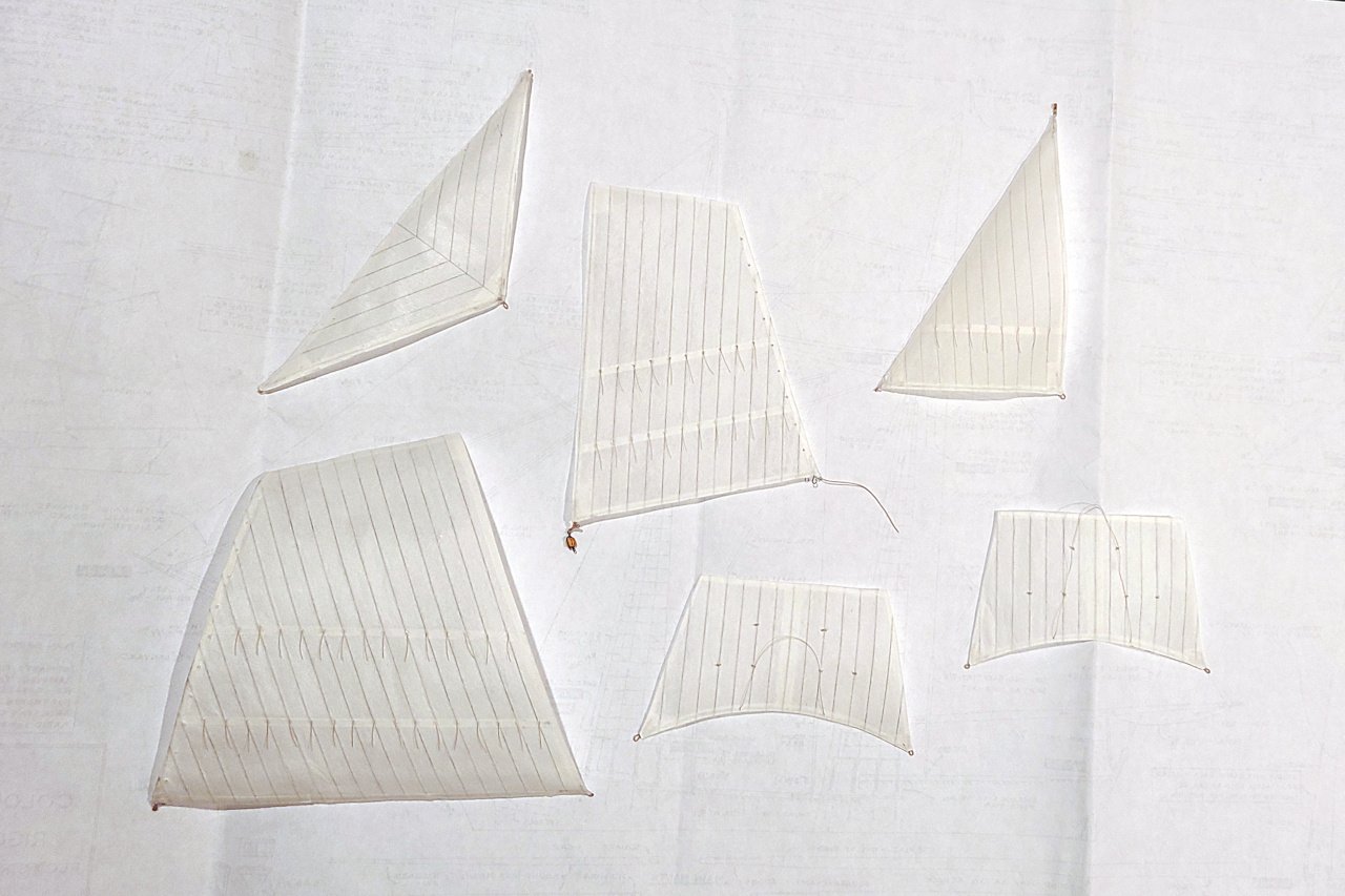
Making sails... I had the crazy idea of putting wire inside teabag paper in order to make sails that can be shaped. It was mostly successful, but didn't fully achieve what I wanted. For all the details, have a look here: https://modelshipworld.com/topic/37106-some-silkspan-tips/page/2/#comment-1083821 Once I had wired teabag paper, the sail pattern was marked. Additional strips of teabag paper were glued on for reef bands, edges, and reinforcements And then the sail was cut out. And here they are. As you can see, I have already been experimenting with shaping the sails. Now everything can finally come together. My greatest worry is that, as I work on the rigging, belaying points and other things will become inaccessible, so I've been thinking hard about the best order to assemble everything.

- 222 replies
-
- 6
-
-
- sultana
- model shipways
- (and 1 more)
-
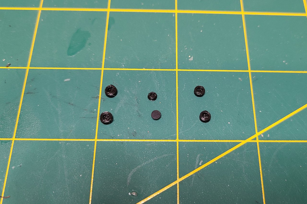
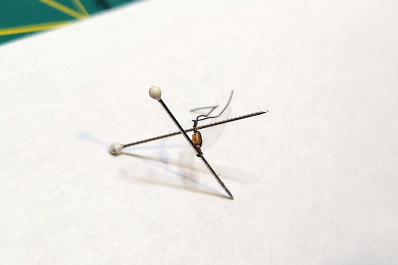
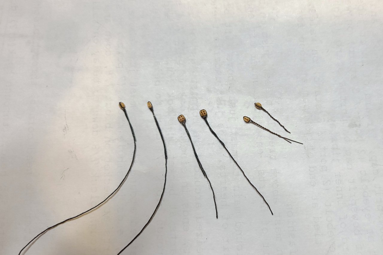
Mark, the kit comes with some wire, but it's not formed into eyelets. I have been making eyelets by wrapping wire around a pin, then around the block. (I really should learn how to do this properly with thread rather than wire. But wire is convenient, especially on the smallest blocks.)
- 222 replies
-
- 1
-
-
- sultana
- model shipways
- (and 1 more)
-
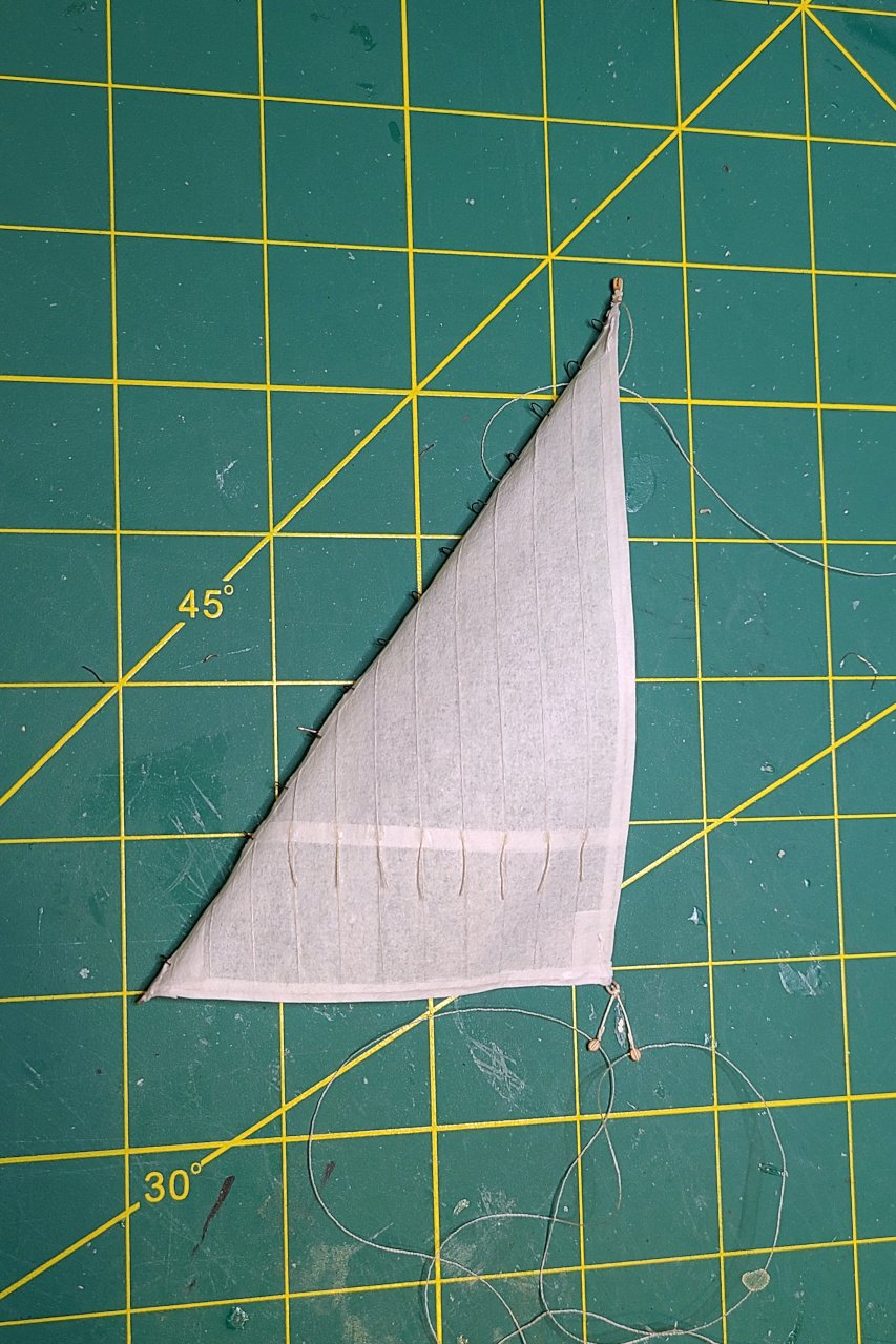
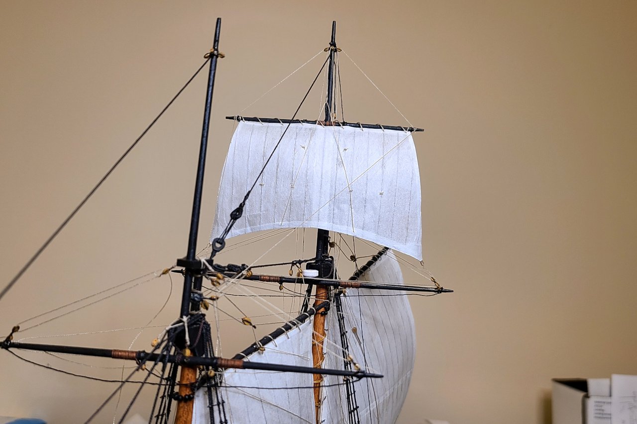
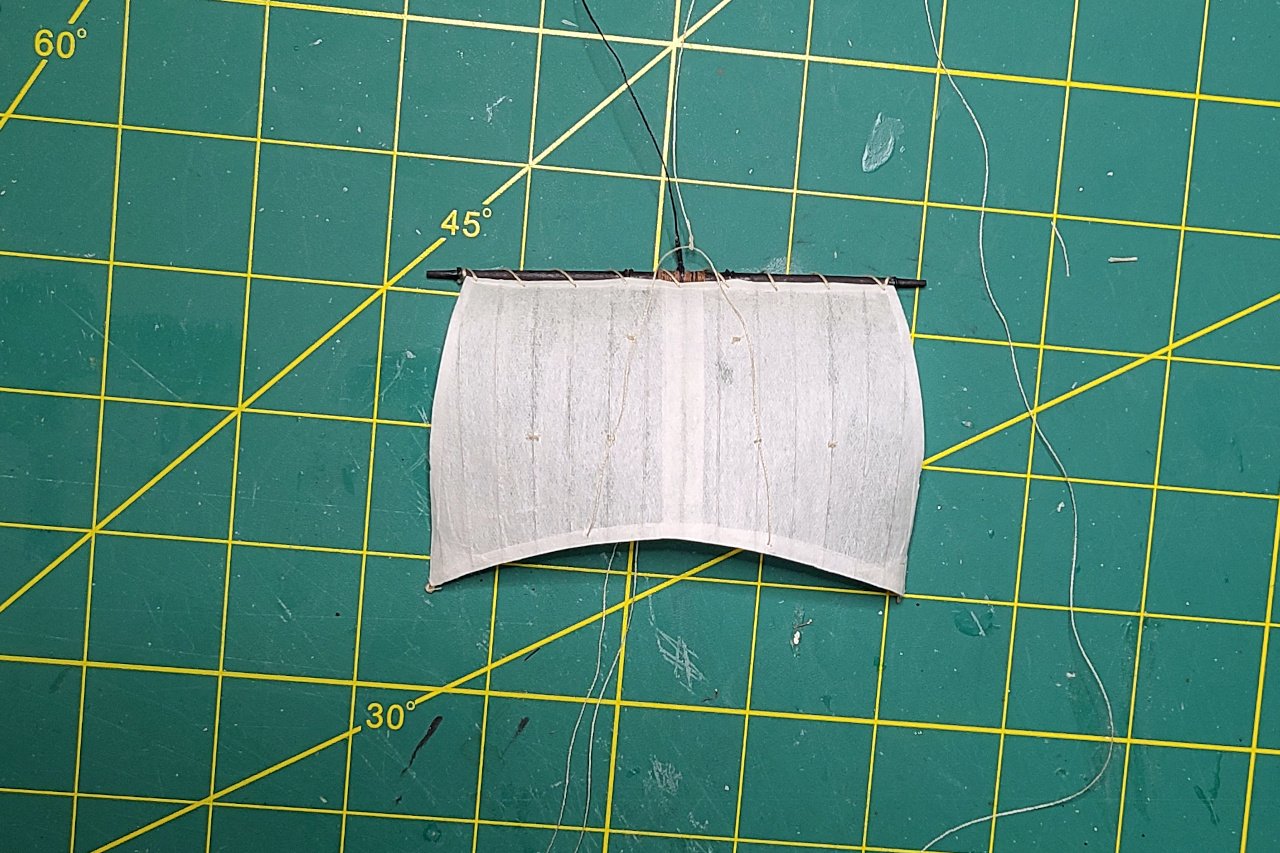
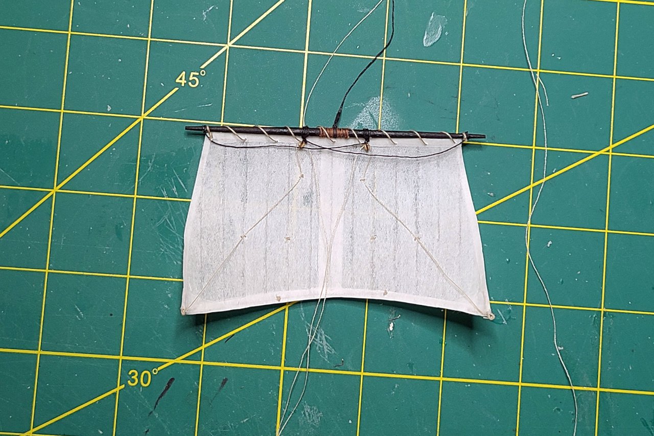
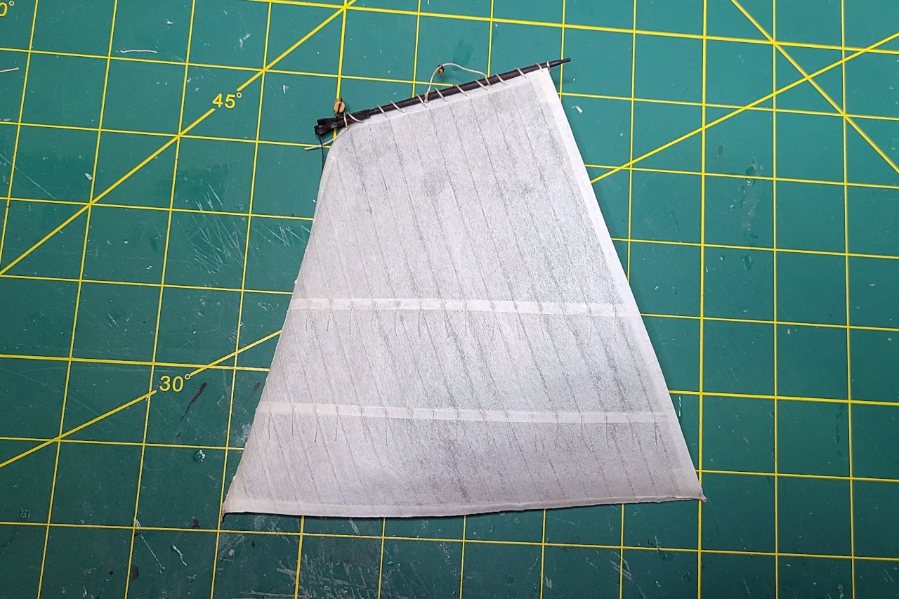
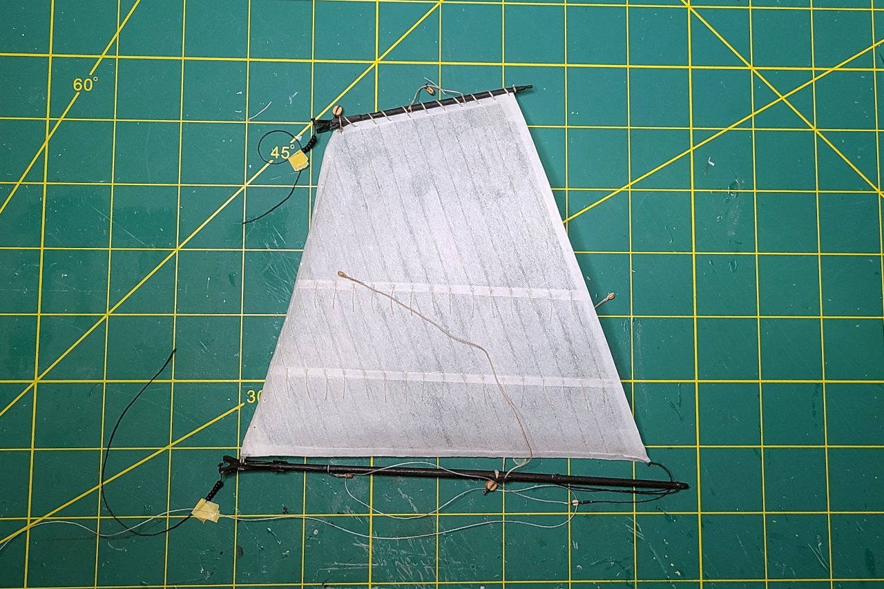
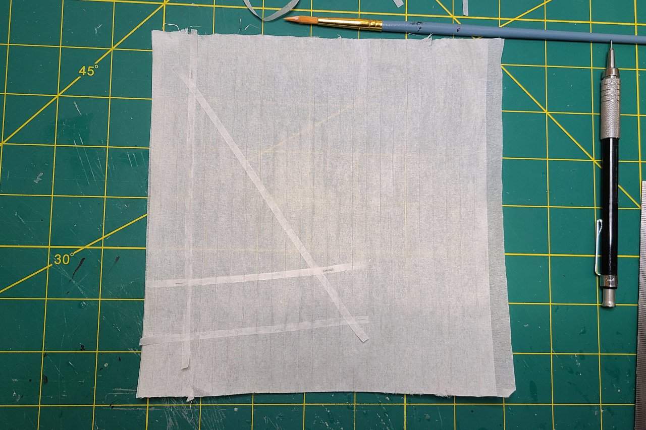
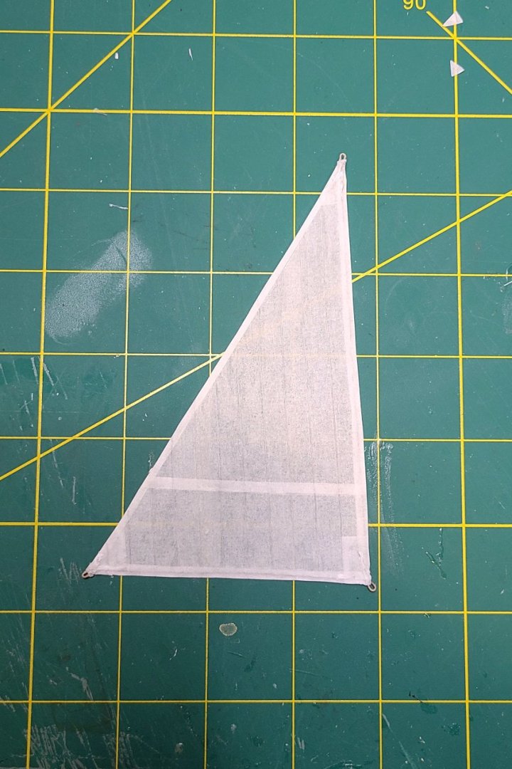
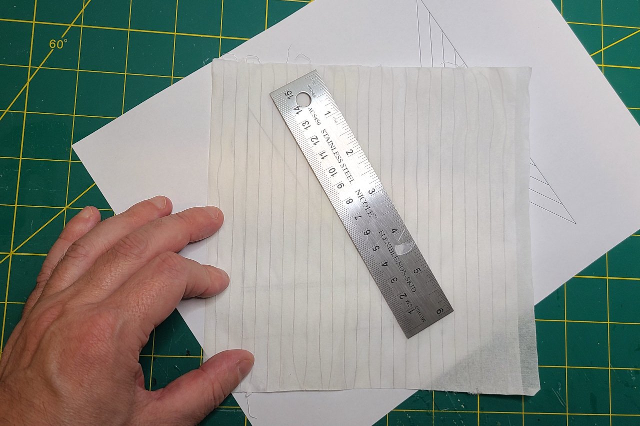
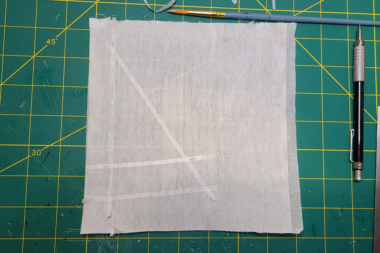
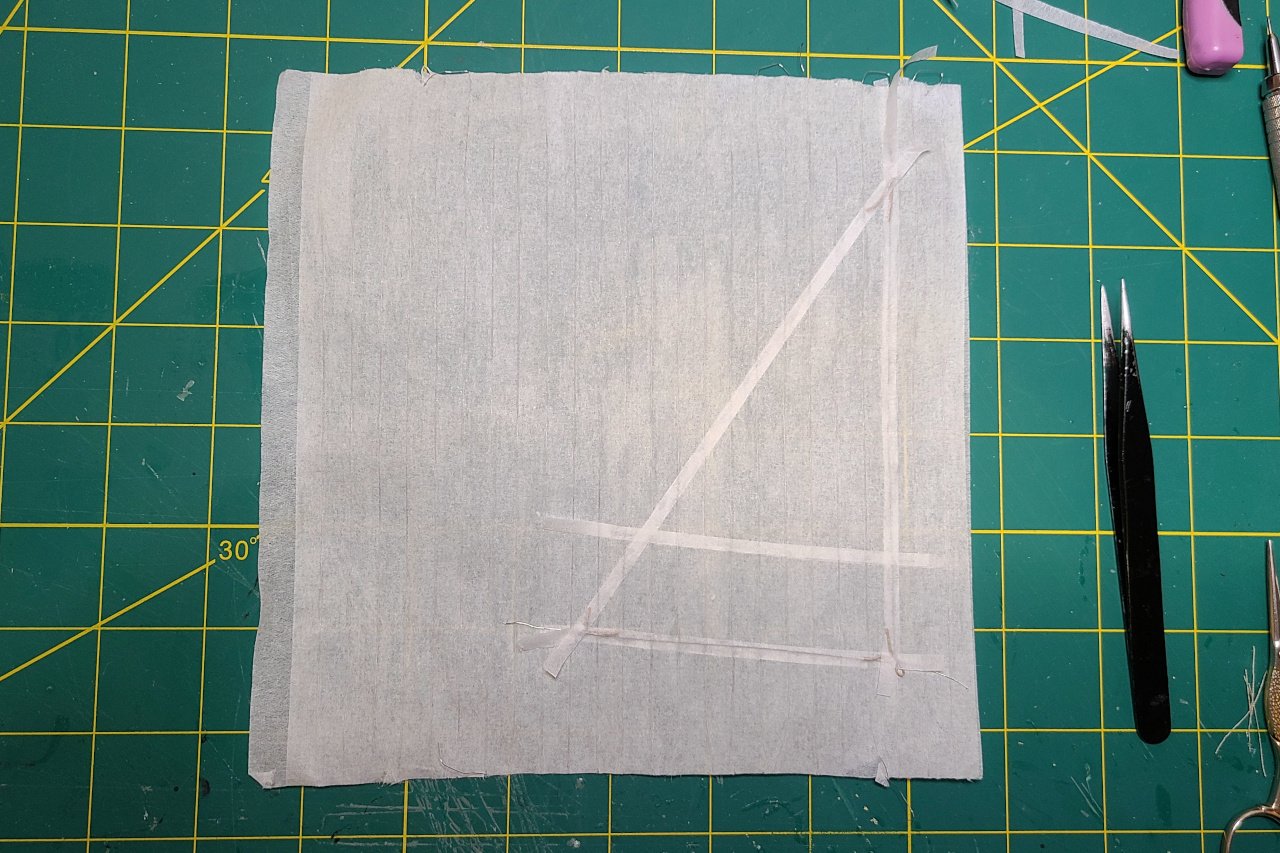
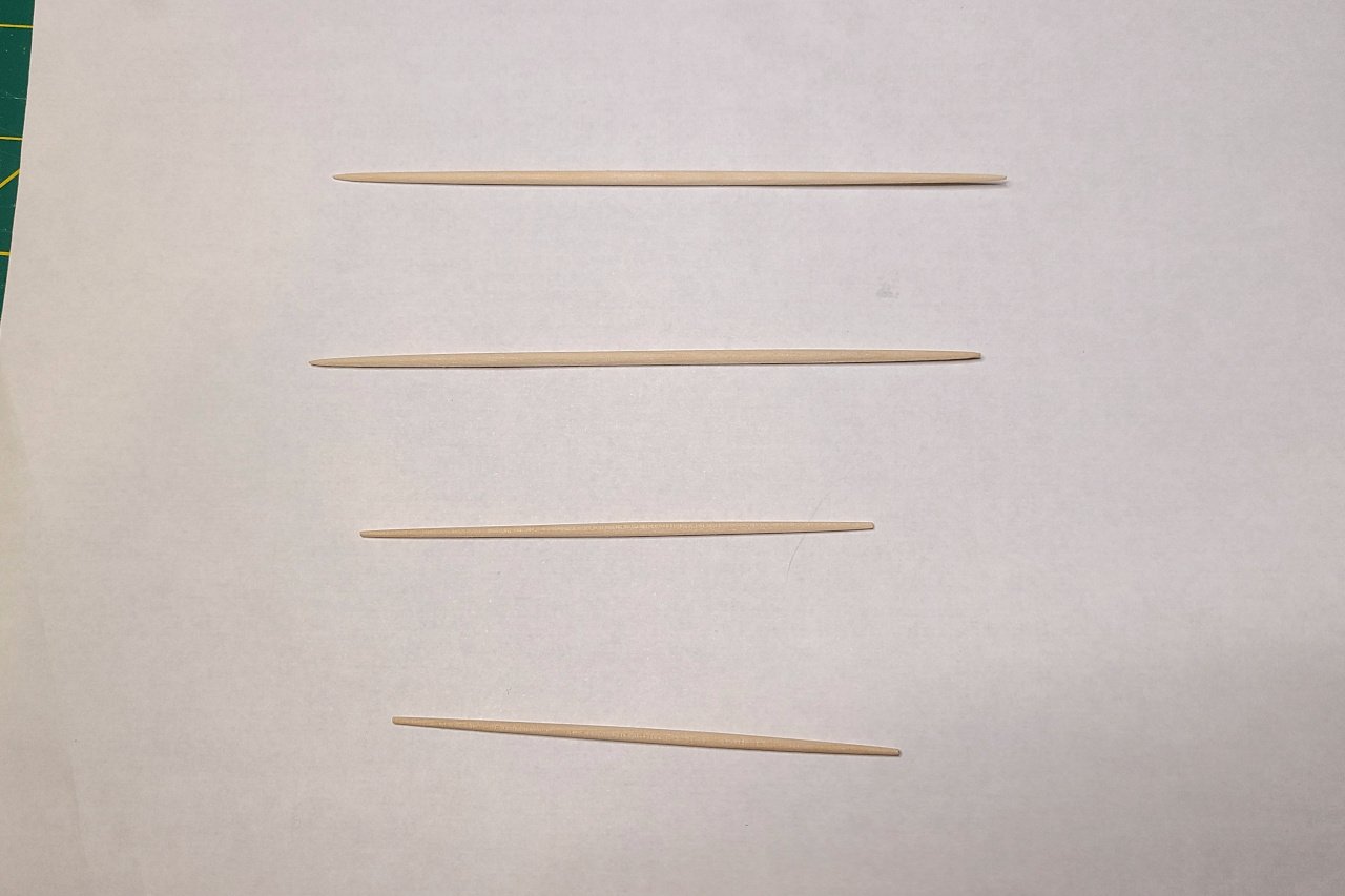
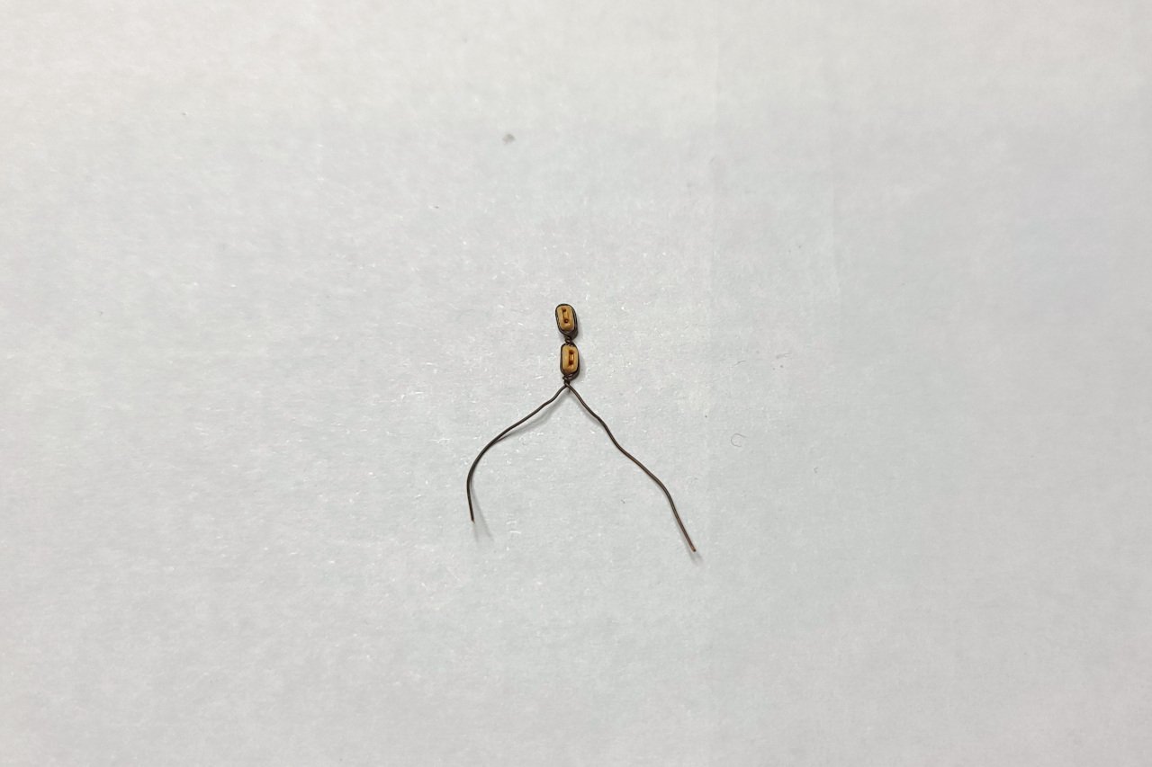
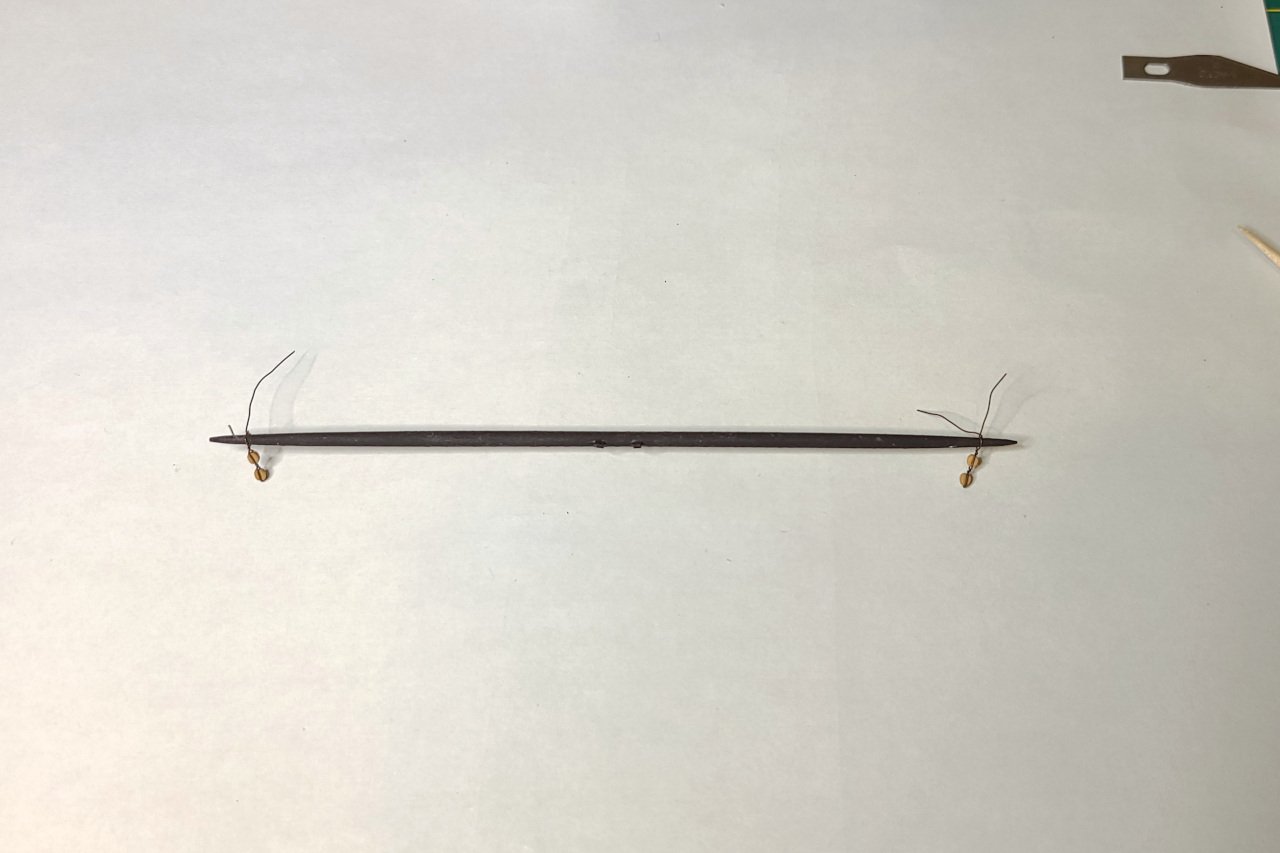
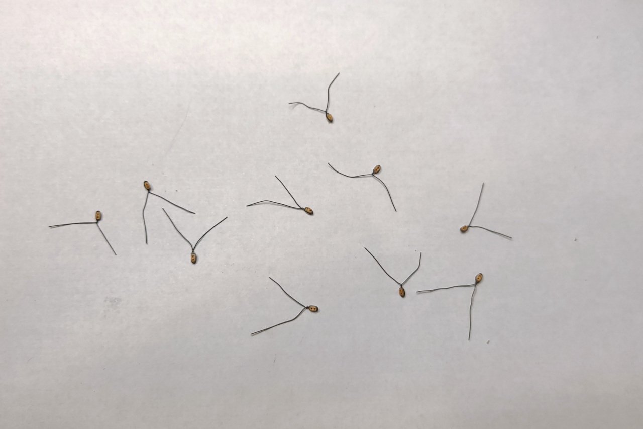
I have been thinking for a while about how to make sails for my Sultana. I want them to look good, of course, but also I want sails that appear full of air. Sails that hang straight down on a schooner just look sad. I purchased some of the material sold as artist teabag paper and have been experimenting with it. On my model, at 1:64 scale, the sail seams would need to be less than half a millimeter wide, with panels 7mm wide. Overlapping the teabag paper to achieve this would be nearly impossible. For such narrow seams, one would typically represent them with lines scribed by a pencil. But in this thread, there was mention of using wire to allow the sails to hold shape. And that got me thinking. What if there were a solution, a crazy solution, that takes care of everything? Below is what I came up with, after a few iterations of testing my ideas. First, the design in Autodesk Fusion. Teabag paper is taped tightly around a piece... ...that fits into the contraption. Then 34 gauge wire is threaded from one end to the other. Glue is spread and a second piece of teabag paper is placed over the first. To do this, I tried both a glue stick, and brushing on white glue. The picture below shows brushed on glue. As you can see, there are some inconsistencies in coverage, and these show up as blotches in the final product (though they aren't as prominent once the glue is dry). With the glue stick, there were fewer blotches, but because the glue stick couldn't fit into the edges, there was glue absent around the border. This allowed some wires to shift inside. Here I start to make the sail, using a pattern printed on office paper. The lines show up fairly well through the two layers of teabag paper. In this picture, by the way, is material from a trial using the glue stick. You can see how wires near the edges have shifted, reducing the usable area. Carefully cut strips of teabag paper are glued on for the reef bands and edge reinforcement. Cringles and an extra wire at the foot of the sail are glued on and covered with teabag paper strips. Once all the gluing is complete, the sail is cut out. It's not too bad. All the wires do allow some shaping of the sail. This picture doesn't show it very well, but there is some decent curvature of the sail, particularly along the edge at the stay. Anyway, I hope you found this interesting.


- 50 replies
-
- 14
-
-
-
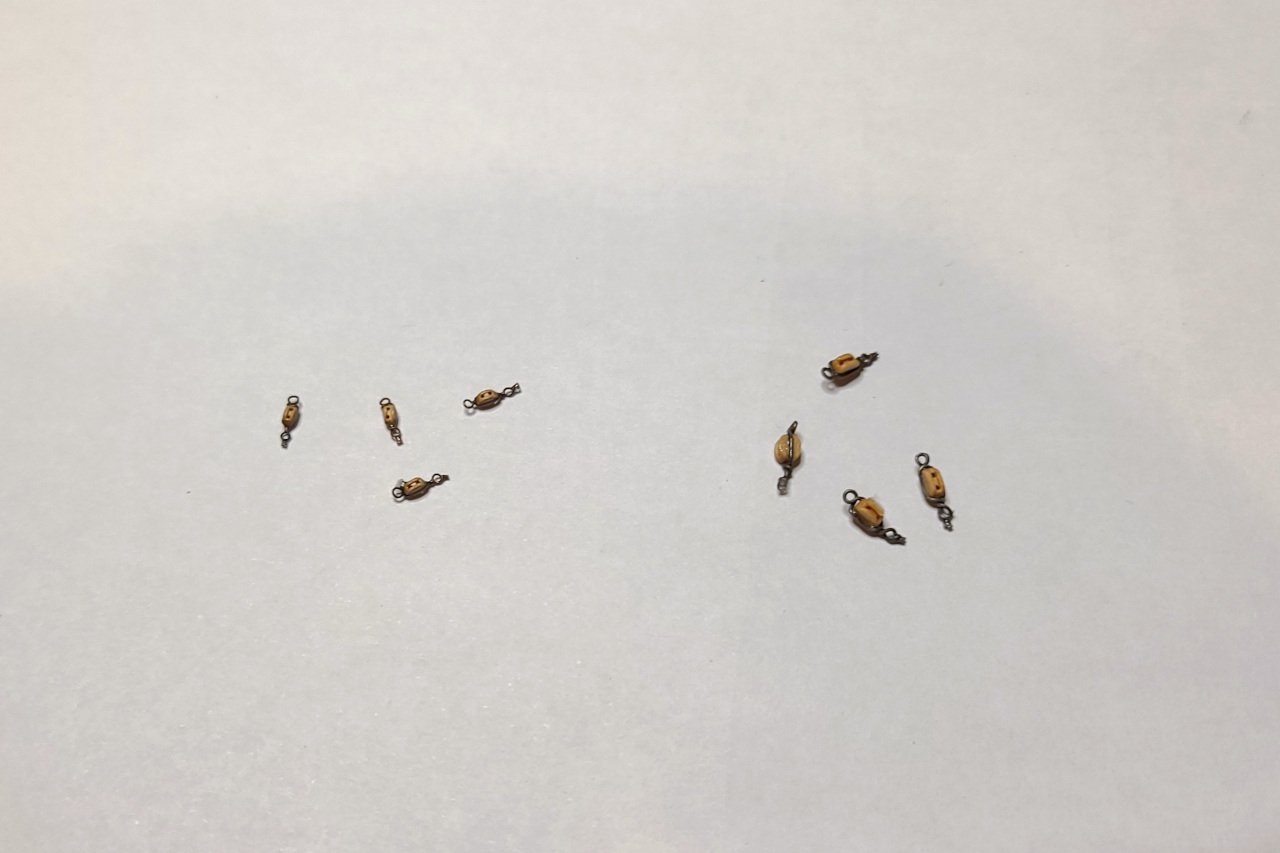
Preparing blocks... Blocks here... Blocks up here... (And this reminds be that I still need to fashion masthead trucks.) Blocks all over... There will be 102 blocks in total. Everything is ready for the running rigging at this point, but there's a final major task to work through. That'll be next time.
- 222 replies
-
- 9
-
-
- sultana
- model shipways
- (and 1 more)
-
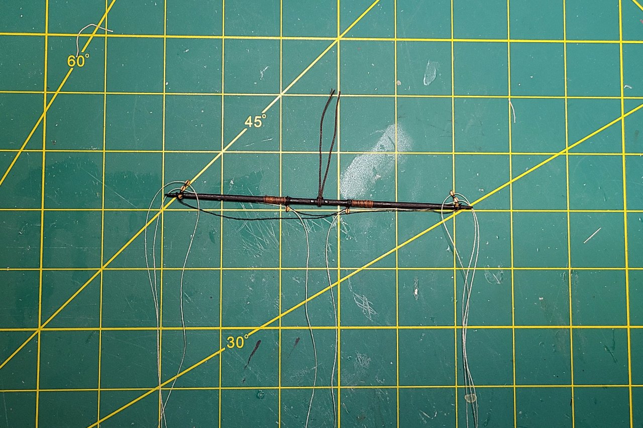
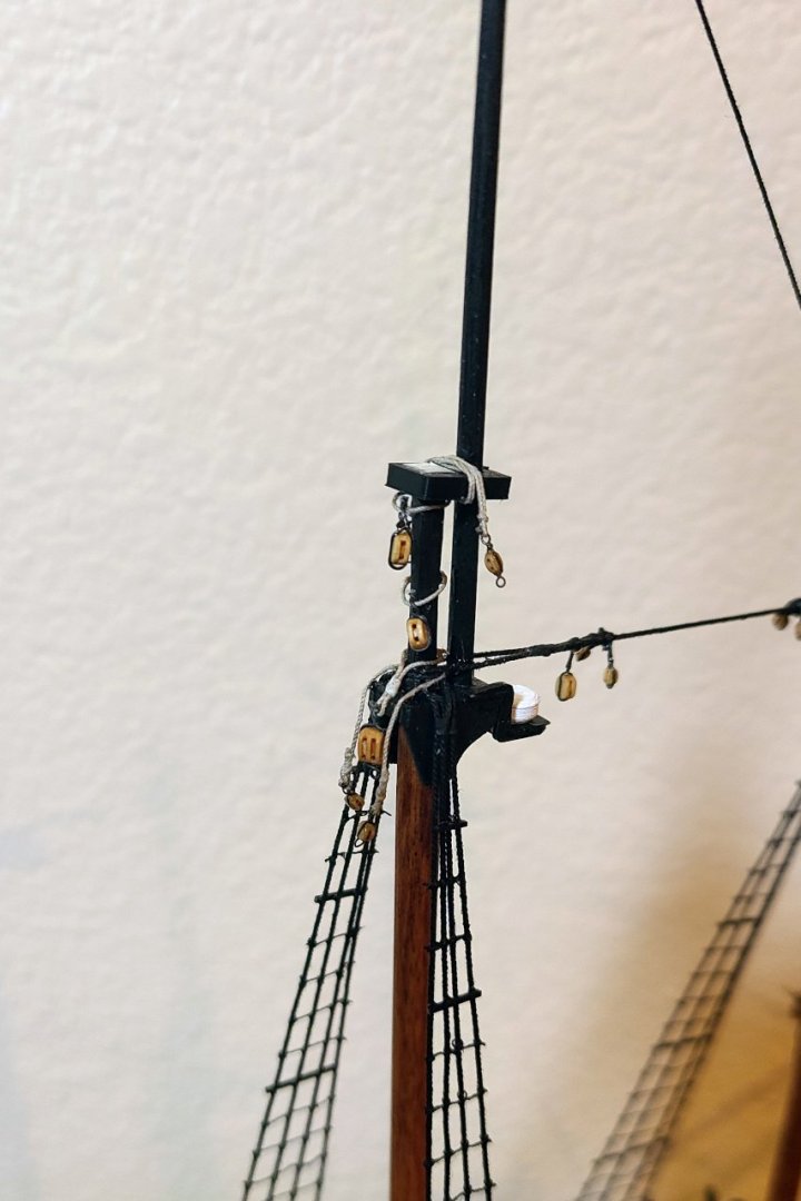
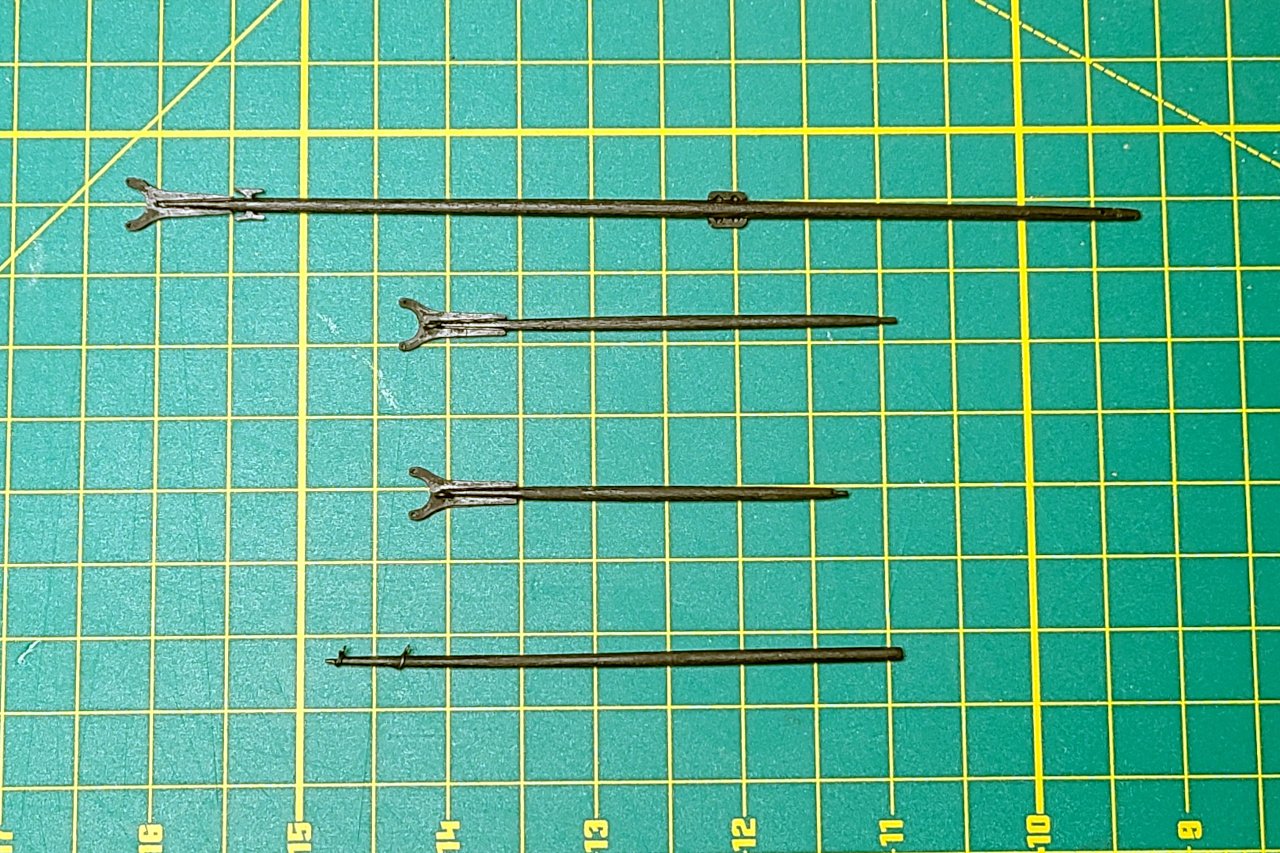
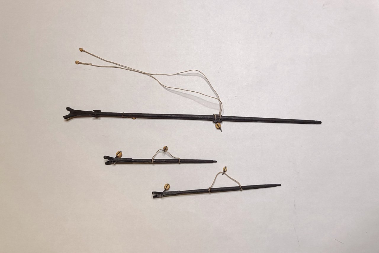
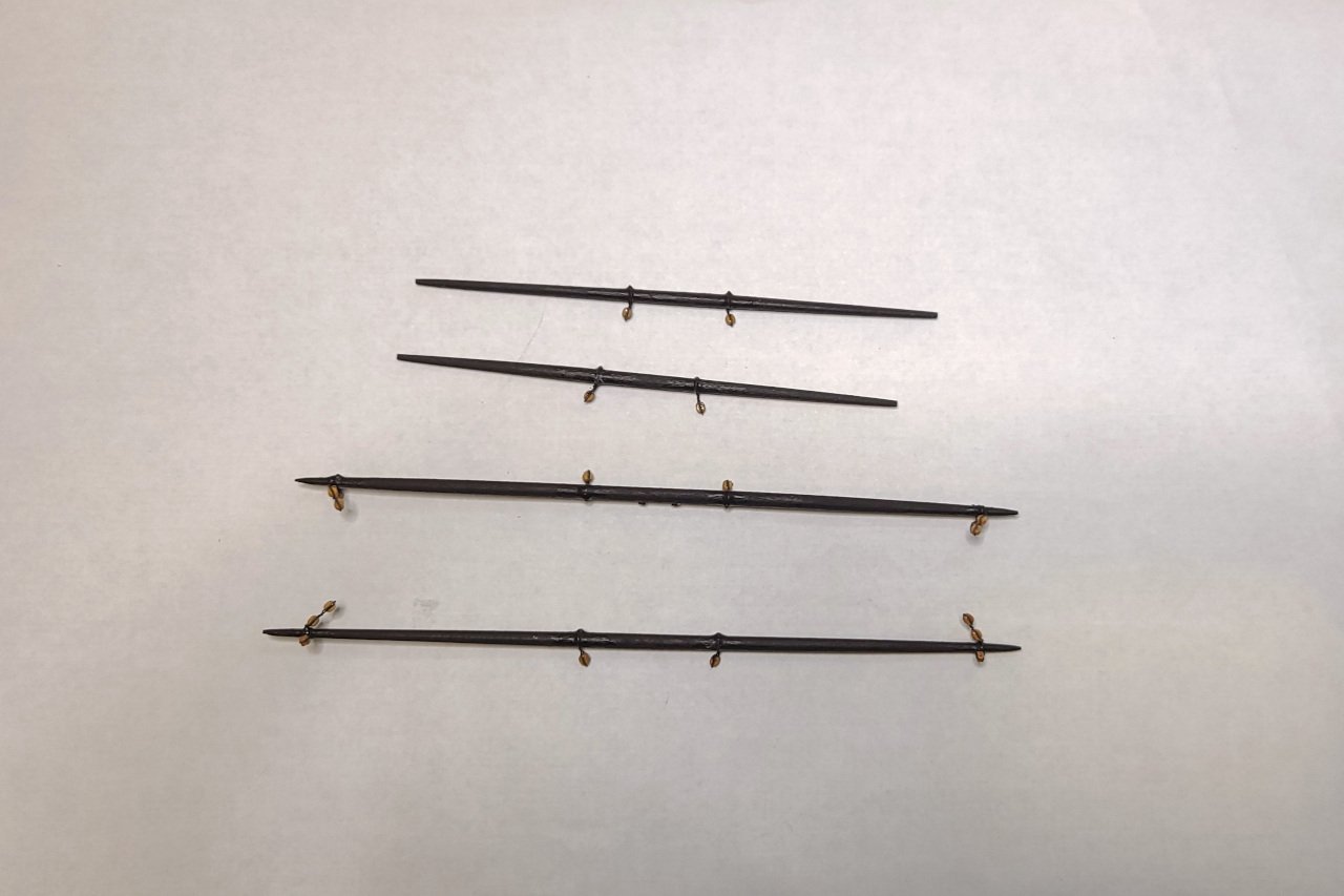
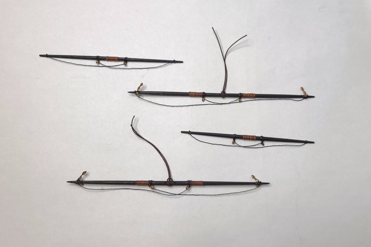
Here's a picture from a while ago when I made the boom, gaffs, and jibboom. The boom and gaffs have had blocks and some rigging elements added. Now to make the topsail yards. These require a lot of tiny 2mm blocks. I have been using blackened 30 gauge wire to attach them to the yards. And then footropes and other elements are added.
- 222 replies
-
- 6
-
-
- sultana
- model shipways
- (and 1 more)
-
Enjoy. I hope the pictures answer more questions than they create. (One peculiarity I noticed is that the gaff throat halliard is completely absent on the model.)
-
So, I happened to be visiting family in the Toronto area over the holidays and went to see the Surly model at the Art Gallery of Ontario. My pictures have been posted. I hope they are useful to vossiewulf and others.
-
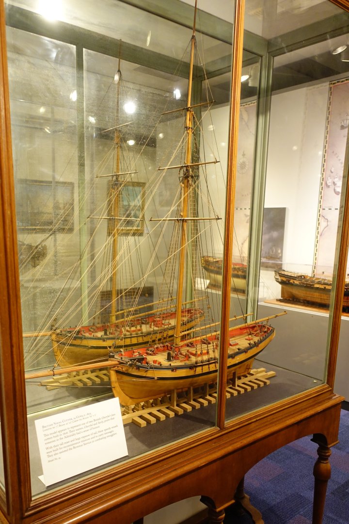
The Cheerful model at the US Naval Academy museum has three yards. I have lots of pictures, if you're interested.