HOLIDAY DONATION DRIVE - SUPPORT MSW - DO YOUR PART TO KEEP THIS GREAT FORUM GOING!
×


SardonicMeow
-
Posts
333 -
Joined
-
Last visited
Content Type
Profiles
Forums
Gallery
Events
Everything posted by SardonicMeow
-
 Point, I would also appreciate it if you could show us in more detail how to reached this point. I'd love to see, in more detail, how you did the work in the Form workspace. Floyd, have a look at my Sultana build log (which I really do plan to get back to once the summer is over). I modeled the hull in Fusion 360, took cross-sections, and then laser-cut pieces from those. (My cross-sections were created using the Intersect operation, not any add-on. I'll have to see what Slicer can do.)
 -
Regarding the loop, I used cloth covered wire there. The hidden wire is why it holds its shape. (I should point out that a loop like that isn't how the line would be attached on an actual ship.)
- 68 replies
-
- 2
-

-
- virginia 1819
- artesania latina
- (and 1 more)
-
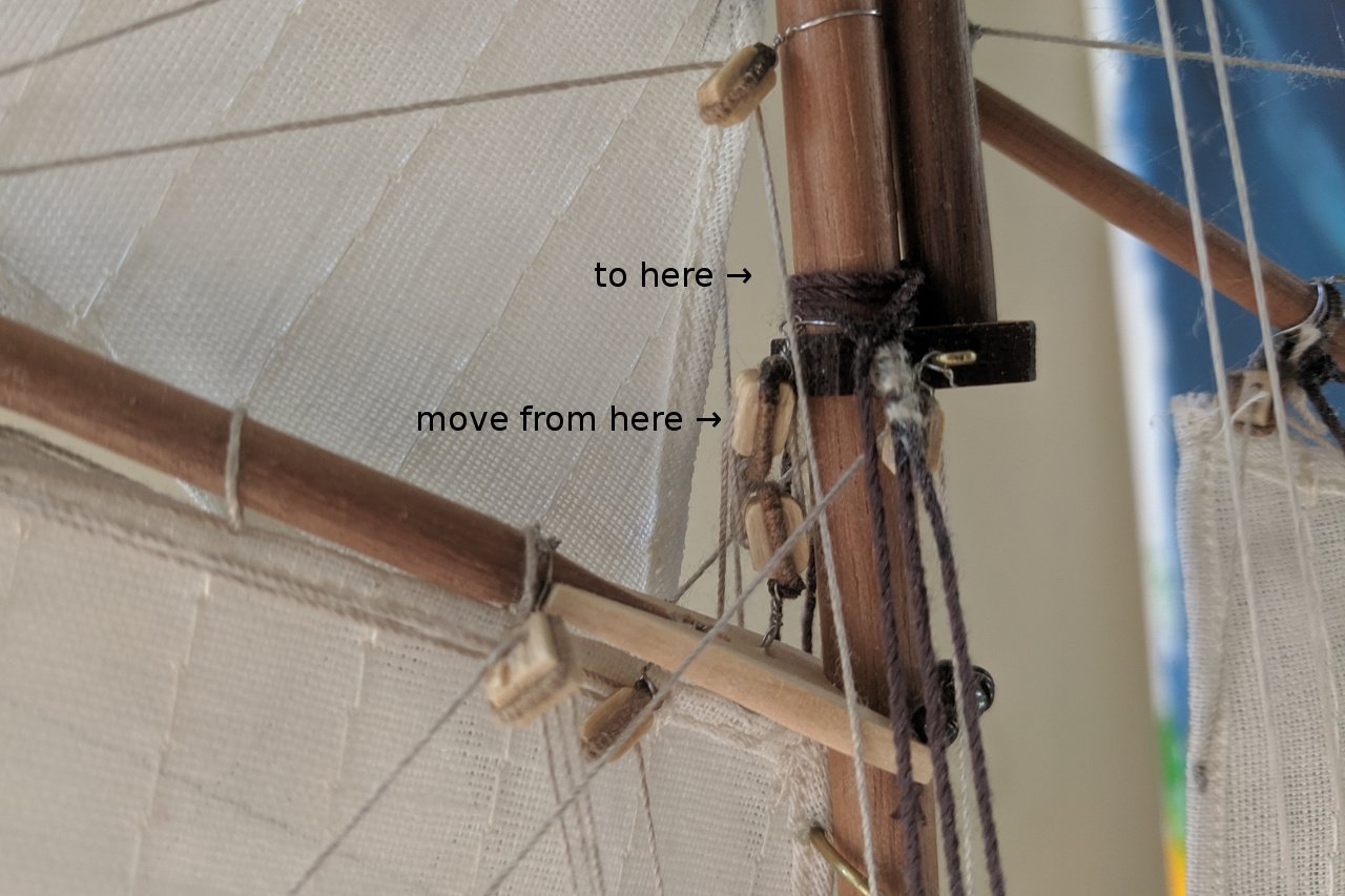
Sorry, but I'm not sure what "loops" you mean. Are you asking how the sails are attached to the gaffs?
-
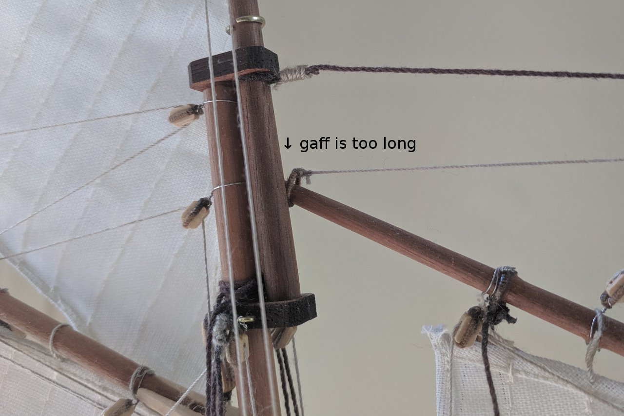
Uh oh. That means you'll inherit my mistakes too. 😀 I'm sure there are other minor problems, but the one that stands out is that I placed that block on the mainmast for the throat halyard too low. It limits how high the gaff can be raised. In the picture below, you can see that the two blocks (one on the gaff, one on the mast) are touching. The other issue that I remember isn't directly related to blocks but may affect your placement of them. If you follow the length in the plans, the foresail gaff is too long and will hit the mainmast no matter how you adjust the lines. I recommend that you cut it a little shorter than the plans show (testing it before you cut, of course). I'll post again if I remember any more issues.


- 68 replies
-
- 3
-
-
- virginia 1819
- artesania latina
- (and 1 more)
-
I've been a proud member since January 2018. 😁 You're doing great, Matt. Once you work around the rudder issue, all the most frustrating parts are behind you.
-
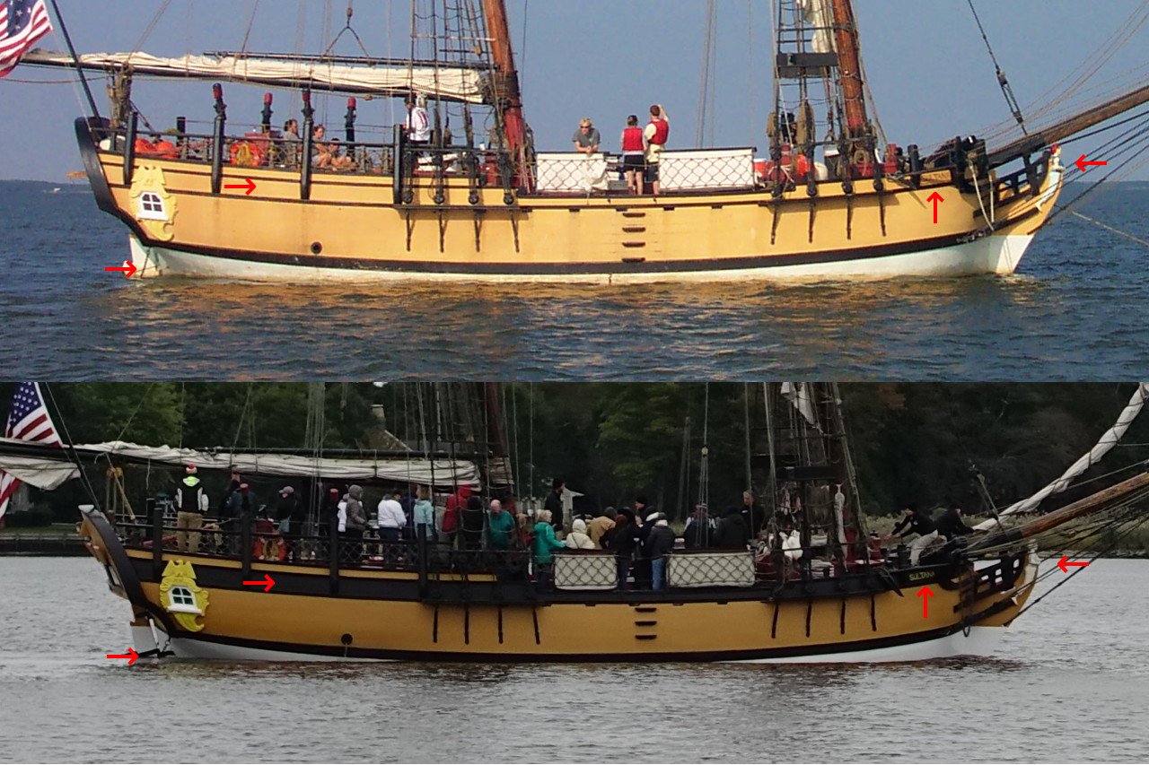
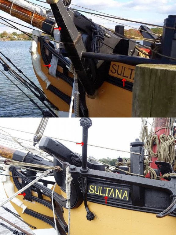
Ships are living things that change over time. I am approaching a point where I'll have to make some decisions about what specific point in time I'll depict in my model. Here are two pictures of the Sultana. The top one is from the blog ship25bsa.smallsquareddesigns.com and was taken August 2003. The lower picture was taken by me in October 2018. The most obvious change is the black stripe painted between the planksheer and caprail. The nameplate at the bow was changed to match. The painted figurehead in the older picture is a rare sight. Nearly every other picture I've found has the figurehead solid white, and I plan to keep it that way. There are other minor changes (like the pintles and gudgeons I have pointed out), as well as other minor details not visible in these pictures. What do you think? Do you prefer the older look or the newer look? I think I'm leading toward the older version. Here's another comparison picture. Top is from the blog 829southdrive.blogspot.com November 2014 and the bottom is another of mine from October 2018. It's not obvious from the top picture, but the band between planksheer and caprail is painted black. However, the bow nameplate is still light. Note the light gammoning rope. The only other time I've seen it light is in pictures of the Sultana at launch. I'll be using black gammoning in my model. The big difference in these pictures is the change in the style of anchor.

- 222 replies
-
- 1
-
-
- sultana
- model shipways
- (and 1 more)
-
Clare's build log of the Independence can be found on his website.
-
Brush. I thinned the paint a little, which is why it took several coats, but helped to keep the paint smooth. As long as my brush strokes followed the flow of the planks, they were nearly unnoticeable.
- 222 replies
-
- 2
-
-
- sultana
- model shipways
- (and 1 more)
-
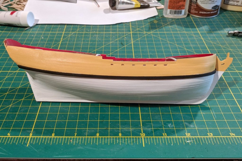
Strips for the wales were bent, painted black, and glued into place. The contrast between the black wales and the light hull colors is striking.
- 222 replies
-
- 7
-
-
- sultana
- model shipways
- (and 1 more)
-
Artist acrylic, because that's what I had on hand. Naples Yellow from Liquitex was the closest match I could find for the yellow color of the hull.
- 222 replies
-
- 2
-
-
- sultana
- model shipways
- (and 1 more)
-
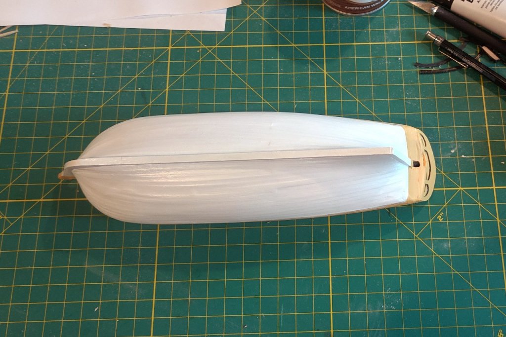
The hull was painted. Multiple coats were required for good coverage.
- 222 replies
-
- 5
-
-
- sultana
- model shipways
- (and 1 more)
-
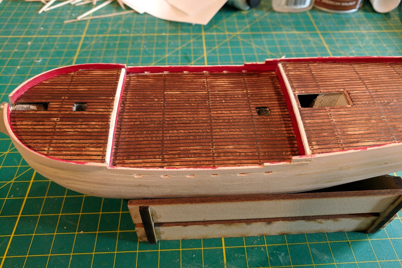
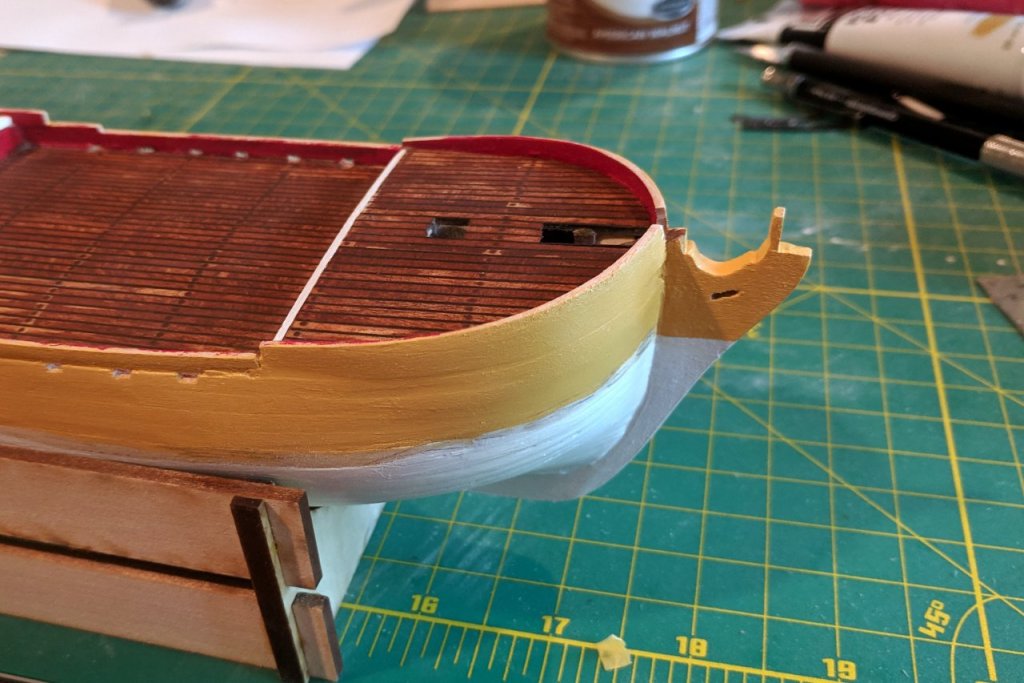
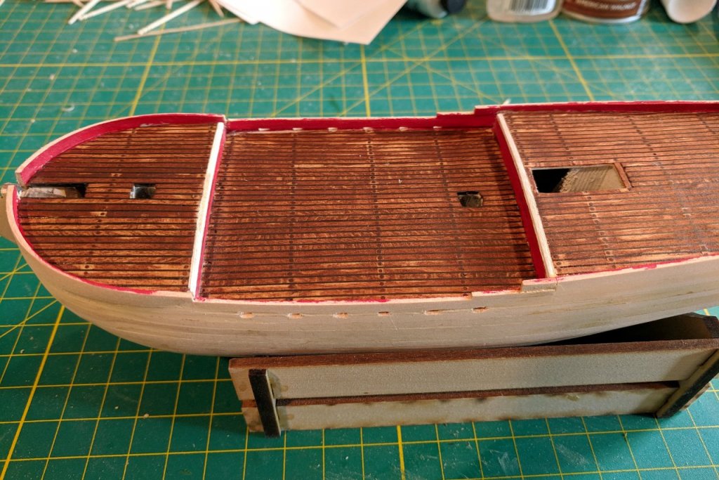
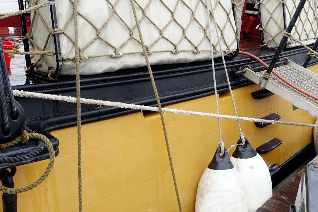
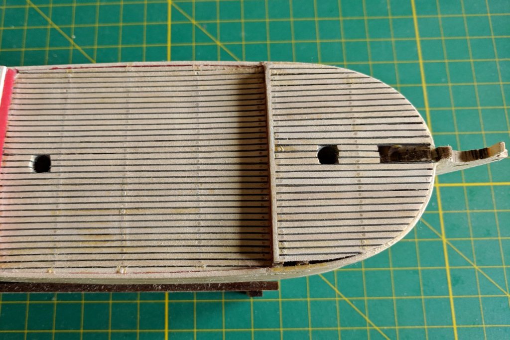
A bad cold and a variety of obligations made me put the build on hold for a few weeks. The deck has been stained. In spite of lots of sanding, there was still enough glue to make the stain cover inconsistently. However, if you look at pictures I've posted of the deck earlier, there is some inconsistency due to weathering, so I'm not too upset. The bulwarks were added and painted red on the inside. Figuring out the right height for the bulwarks was a challenge. Six slots for the scuppers were added on each side of the main deck. I did not completely succeed in making them perfectly rectangular. Here's an image of the scuppers on the real ship.
- 222 replies
-
- 3
-
-
- sultana
- model shipways
- (and 1 more)
-
How does it look with the bowsprit dry-fitted? It seems to me that the bowsprit, more than the windlass, would limit the space to work.
- 574 replies
-
- 3
-
-
- cheerful
- Syren Ship Model Company
- (and 1 more)
-
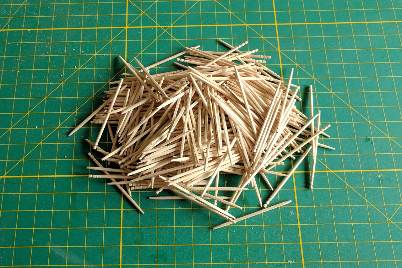
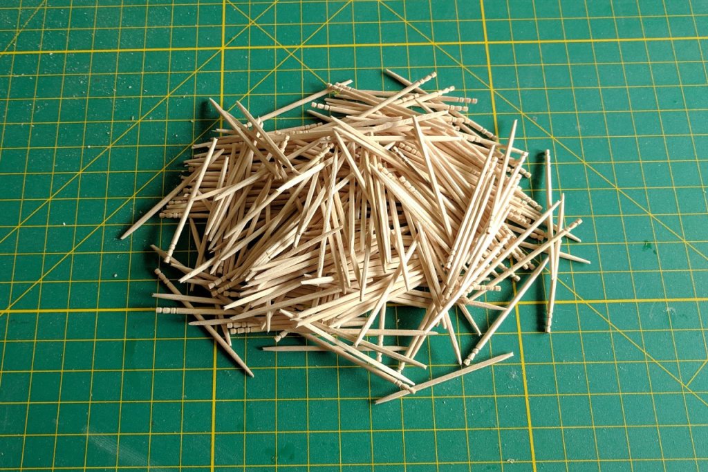
Trenails are done. Next step is to apply stain. What am I to do with all these tipless toothpicks? When someone spends 20 years building the Taj Mahal out of a million toothpicks, is this how it starts?
- 222 replies
-
- 3
-
-
- sultana
- model shipways
- (and 1 more)
-
Yes, those are the exact toothpicks I've been using. 😀
- 222 replies
-
- 1
-
-
- sultana
- model shipways
- (and 1 more)
-
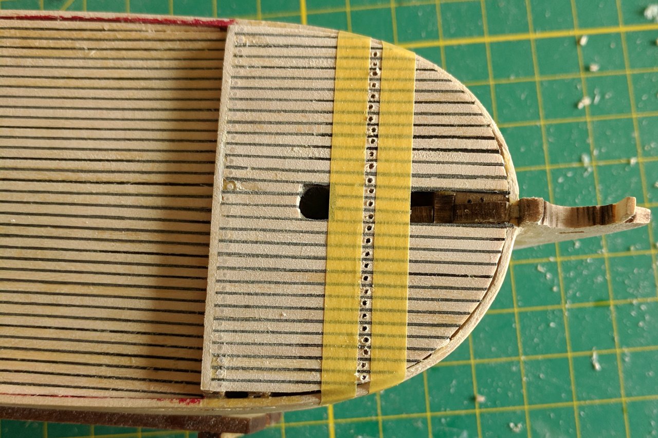
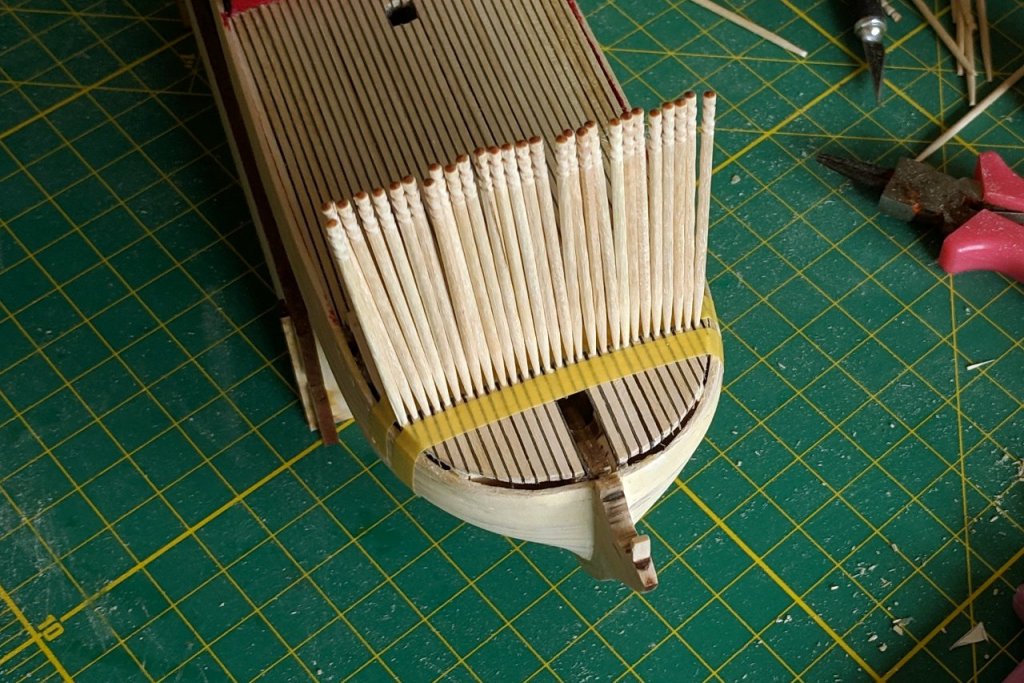
I was hoping to find a less-tedious solution, but after further experiments, I have accepted that the toothpick method is the way to go. I used tape to define the location for the trenails. Holes were drilled along the line. The toothpicks are glued in. After drying, the toothpicks are chopped off and the surface is sanded down. Getting a straight line is a challenge.

- 222 replies
-
- 5
-
-
- sultana
- model shipways
- (and 1 more)
-
Have a look at this update in Blue Ensign's build log for Cheerful. I'm thinking of doing something similar. I'm currently experimenting with several methods, toothpicks included.
- 222 replies
-
- 1
-
-
- sultana
- model shipways
- (and 1 more)
-
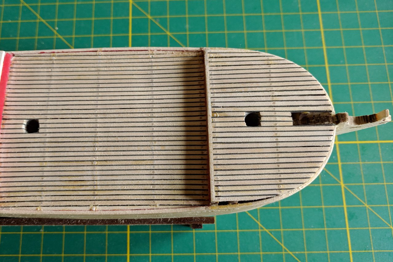
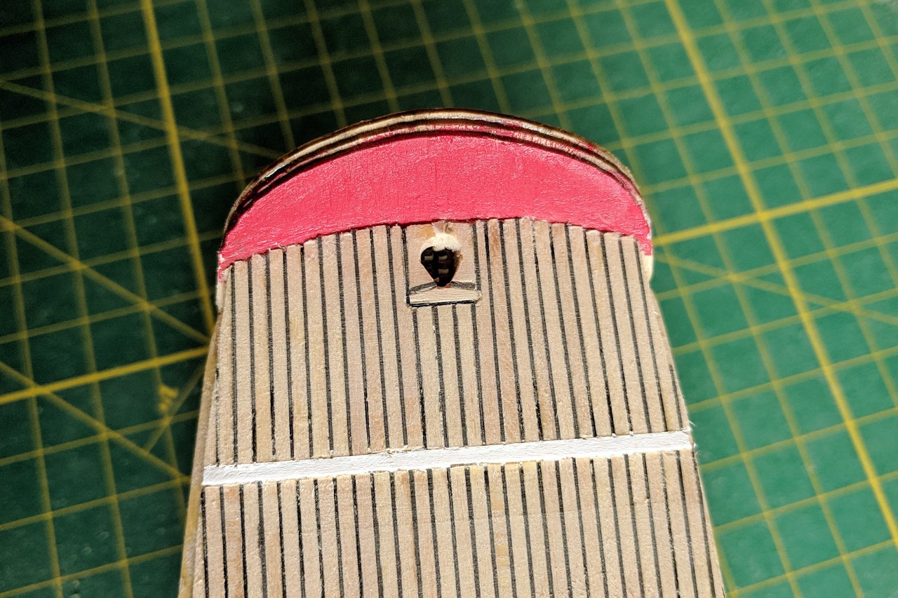
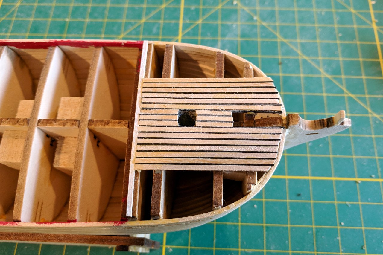
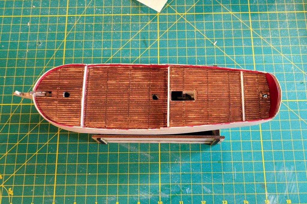
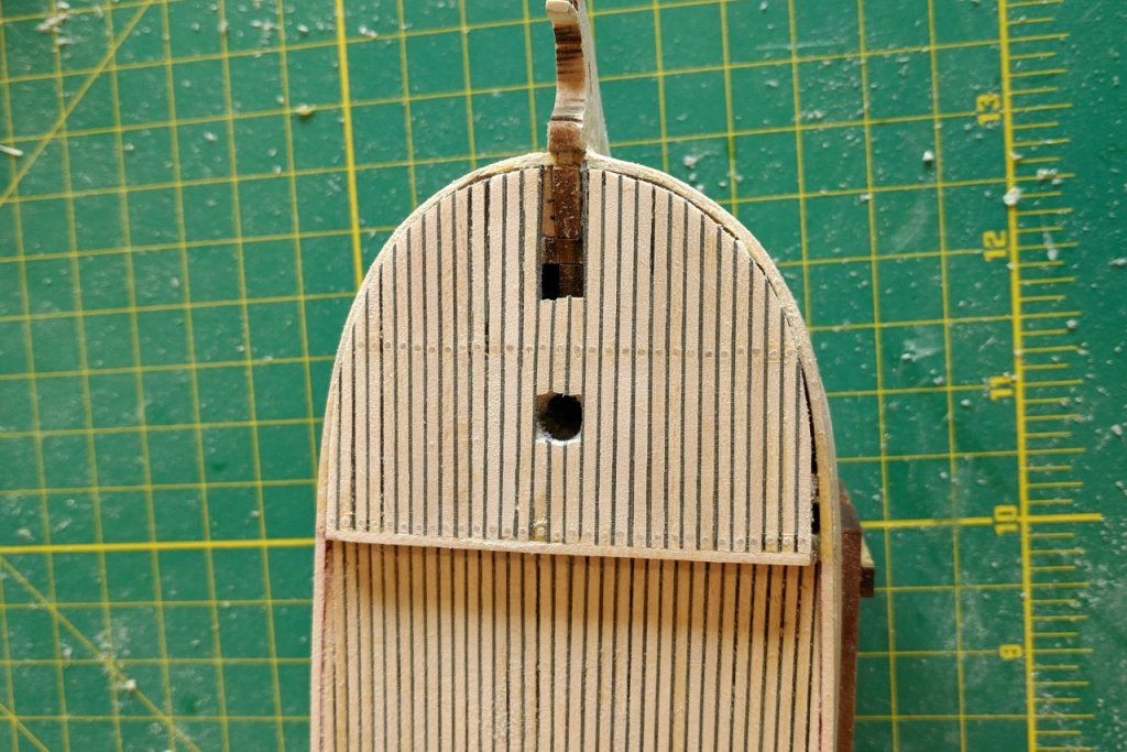
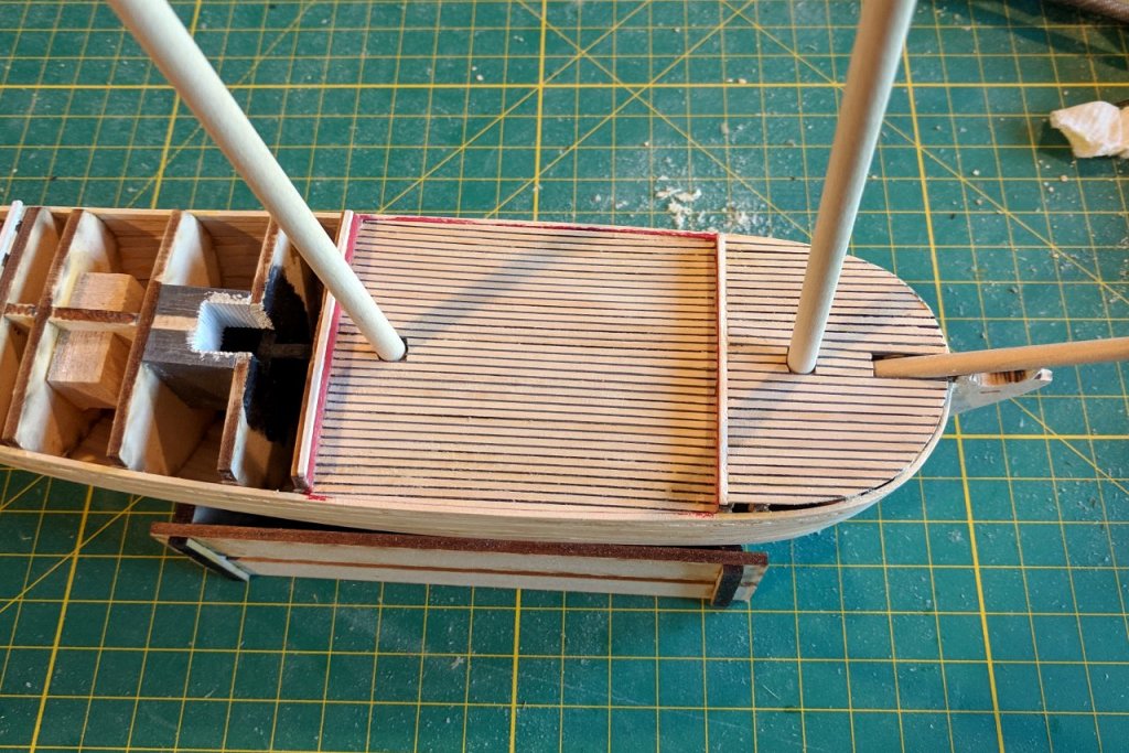
Thank you all for following along. Here are some shots of the planking / caulking procedure. I first cut a length of strip to just larger than the required size, then slowly sand one end a little at a time until it fits perfectly. Then I cut a matching length of the plastic. Glue is applied and the strip is added as shown below, with a tiny space between the old and new strips. Then the plastic strip is put into place between the two deck planks. I start at one end, then run my finger down the length of the strip. After that, the deck plank is firmly pushed into place and excess glue is removed. And at last the deck planking is complete. One particular challenge was the hole for the rudder. This picture on the site ship25bsa.smallsquareddesigns.com was especially helpful in creating the detail of the hole. Next I need to decide how to handle coloring the deck and adding trenails.

- 222 replies
-
- 4
-
-
- sultana
- model shipways
- (and 1 more)
-
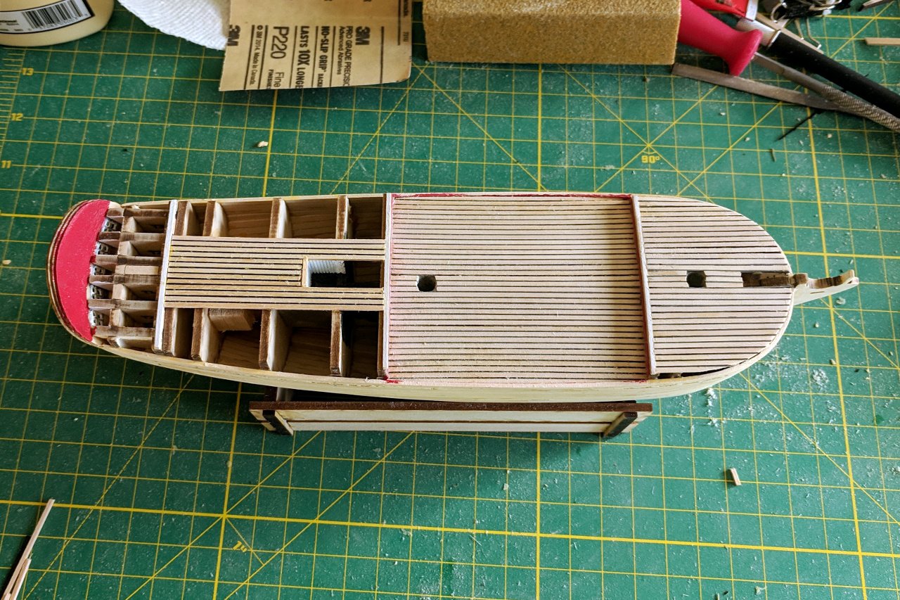
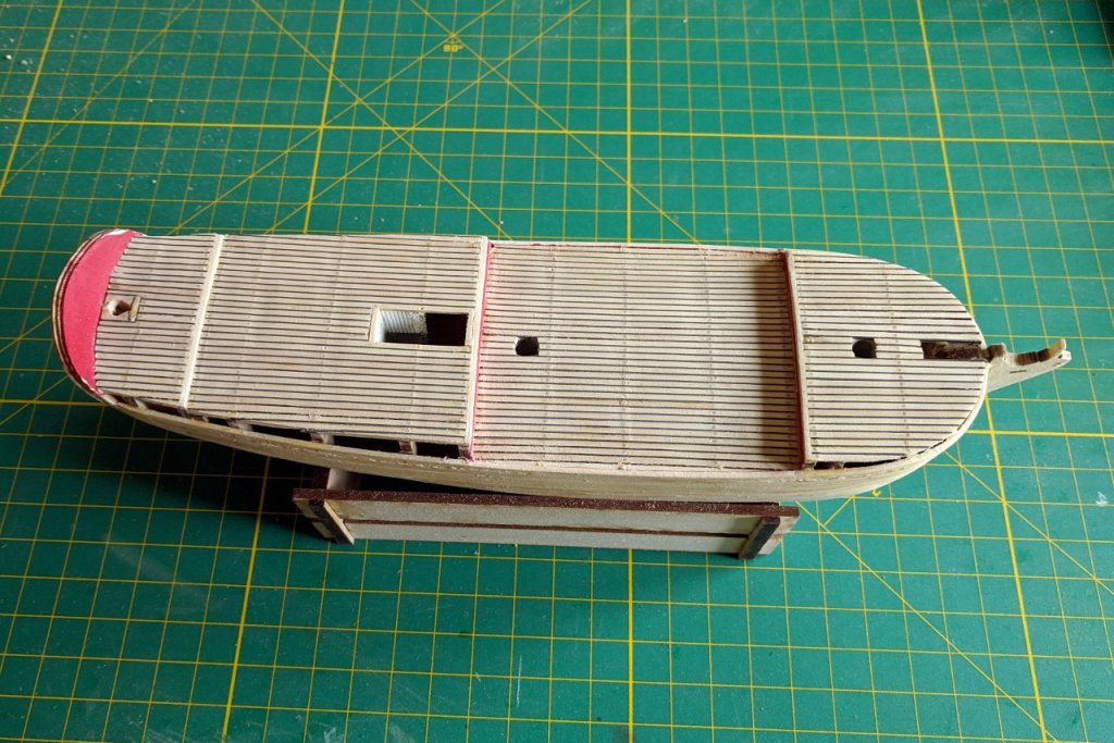
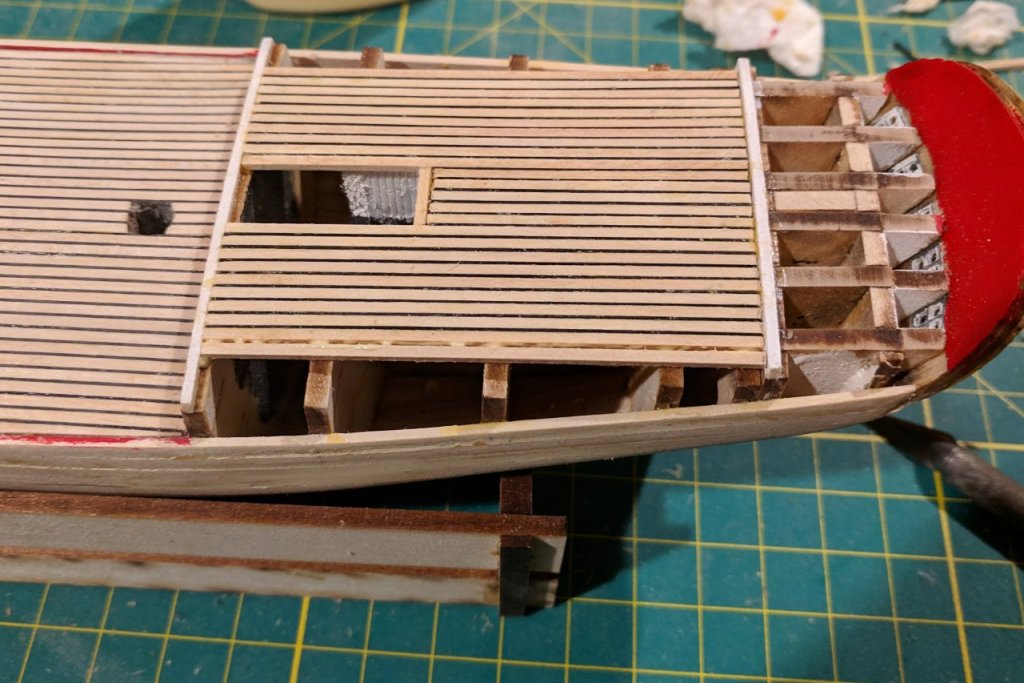
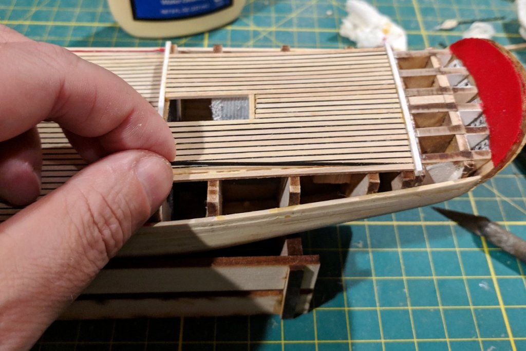
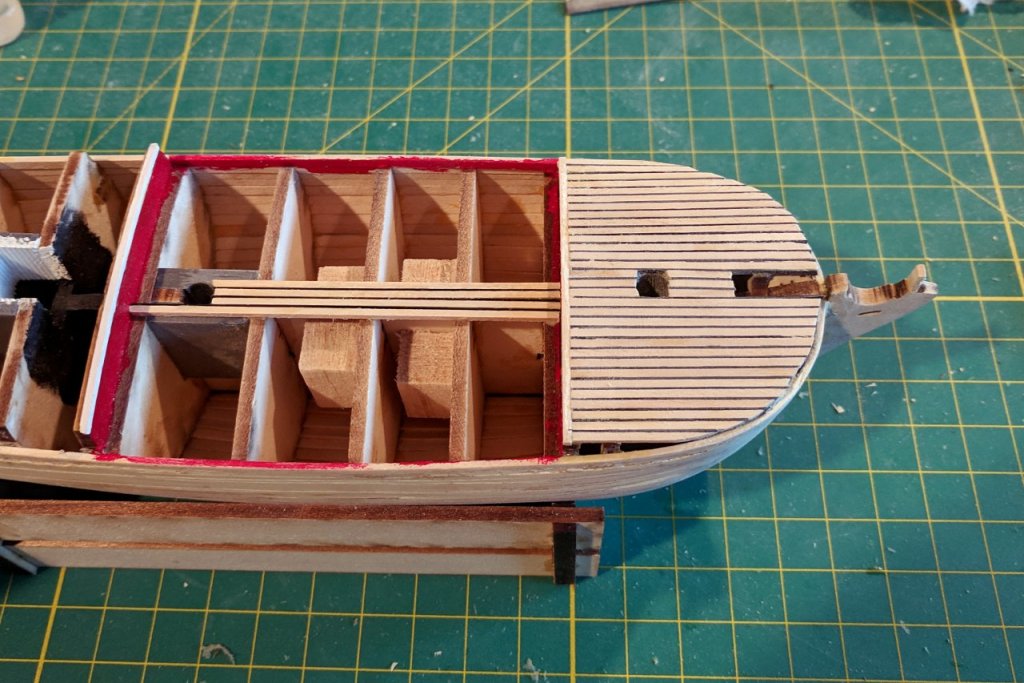
Deck planking continues. I did a test fit to make sure my mast and bowsprit holes were still accessible.

- 222 replies
-
- 4
-
-
- sultana
- model shipways
- (and 1 more)
-
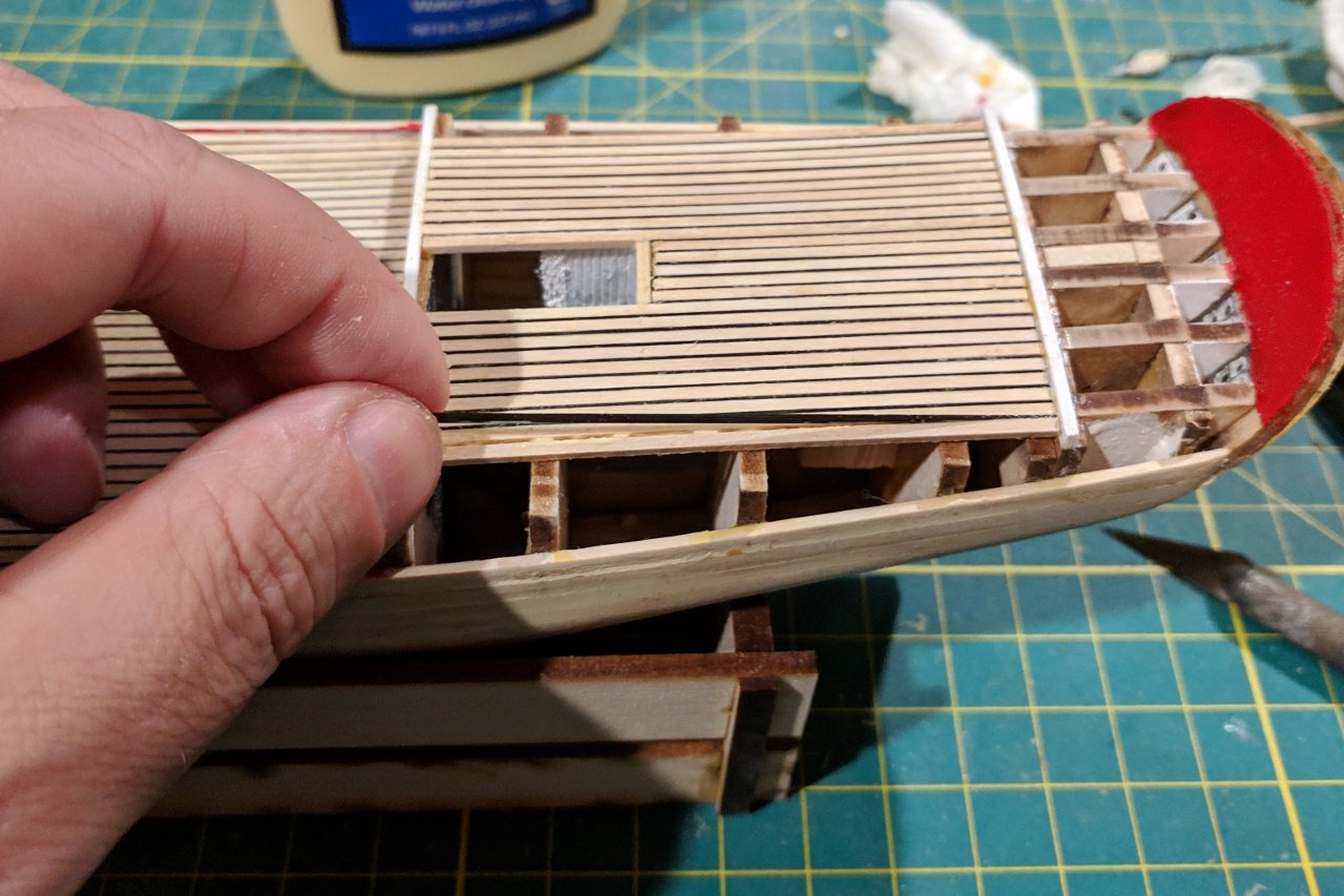
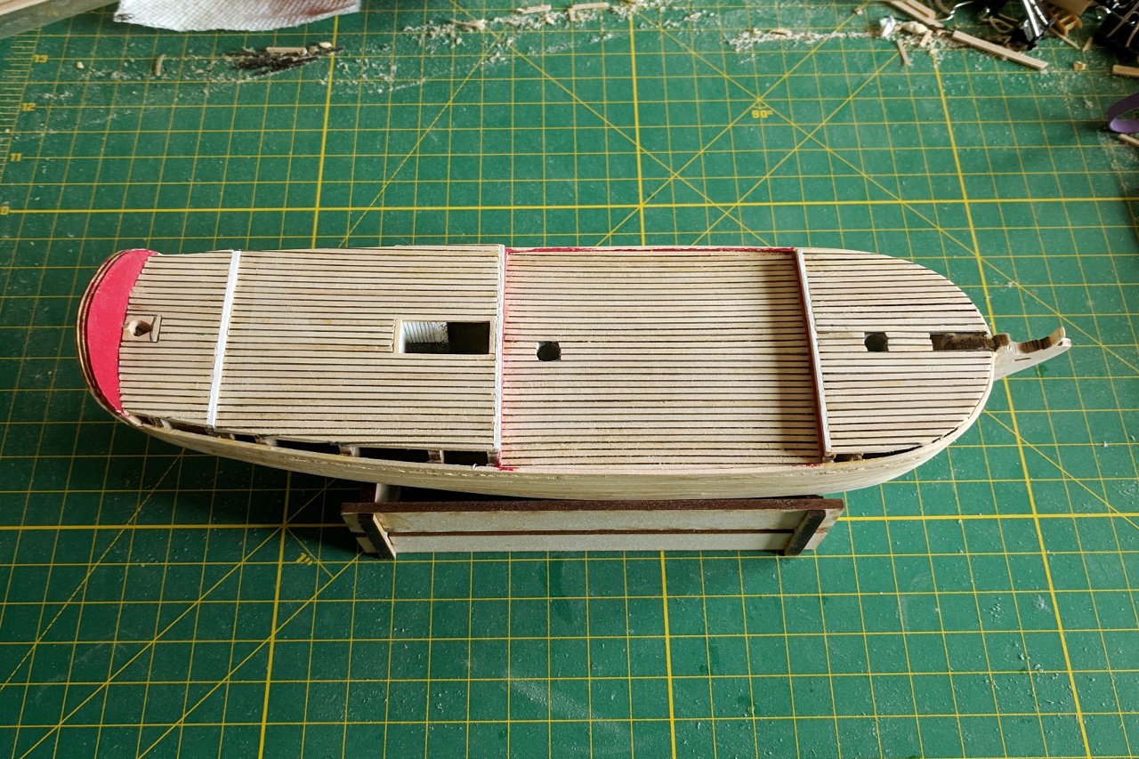
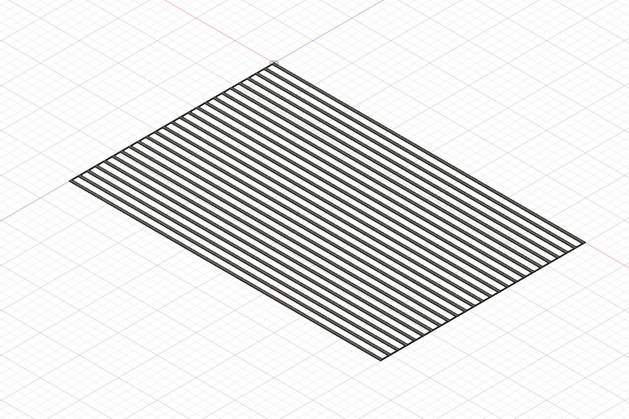
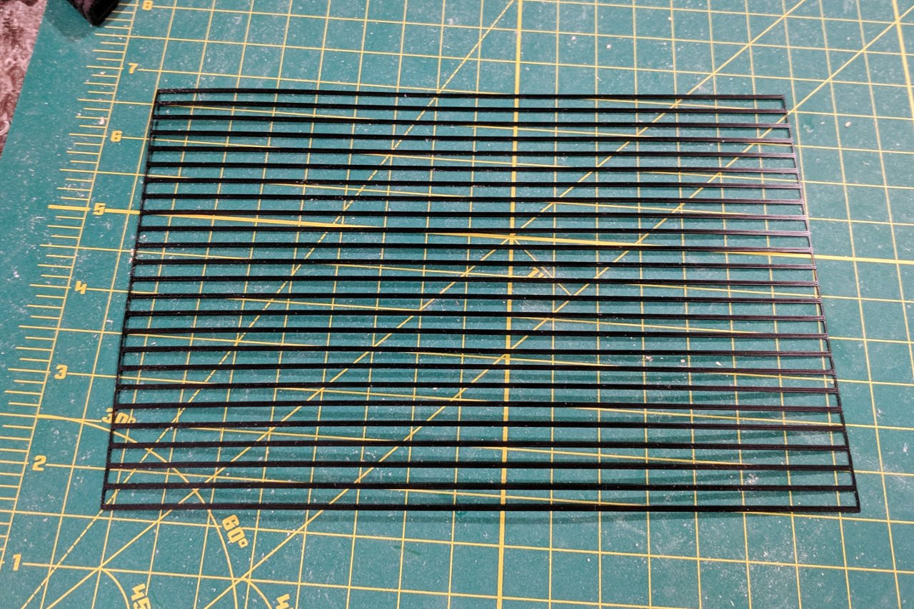
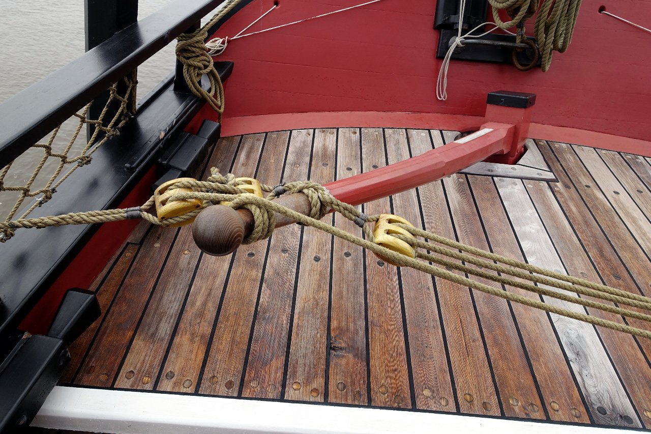
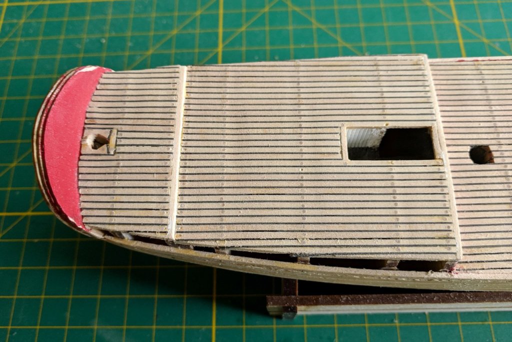
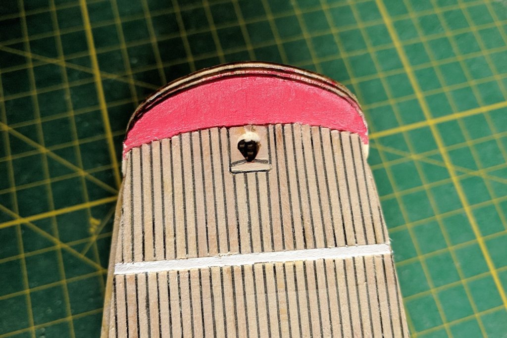
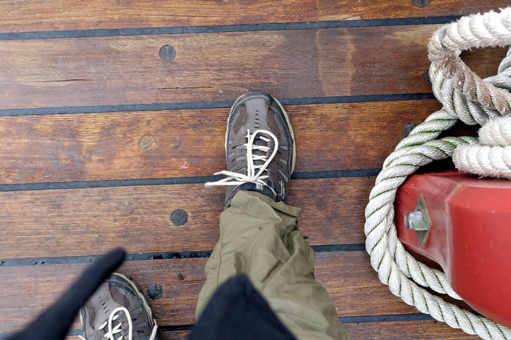
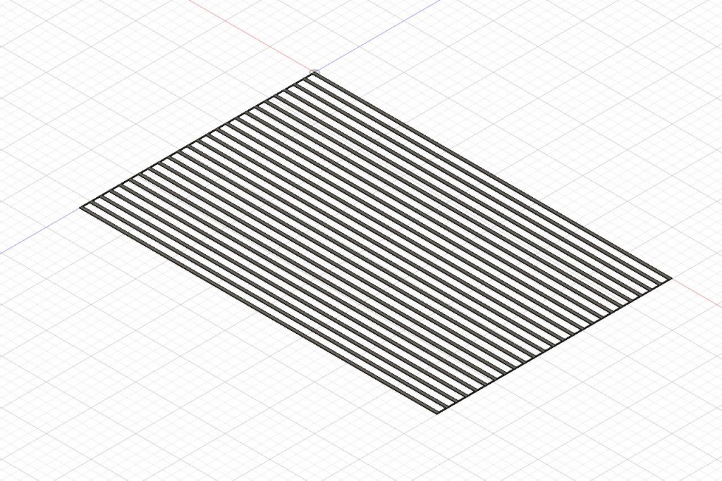
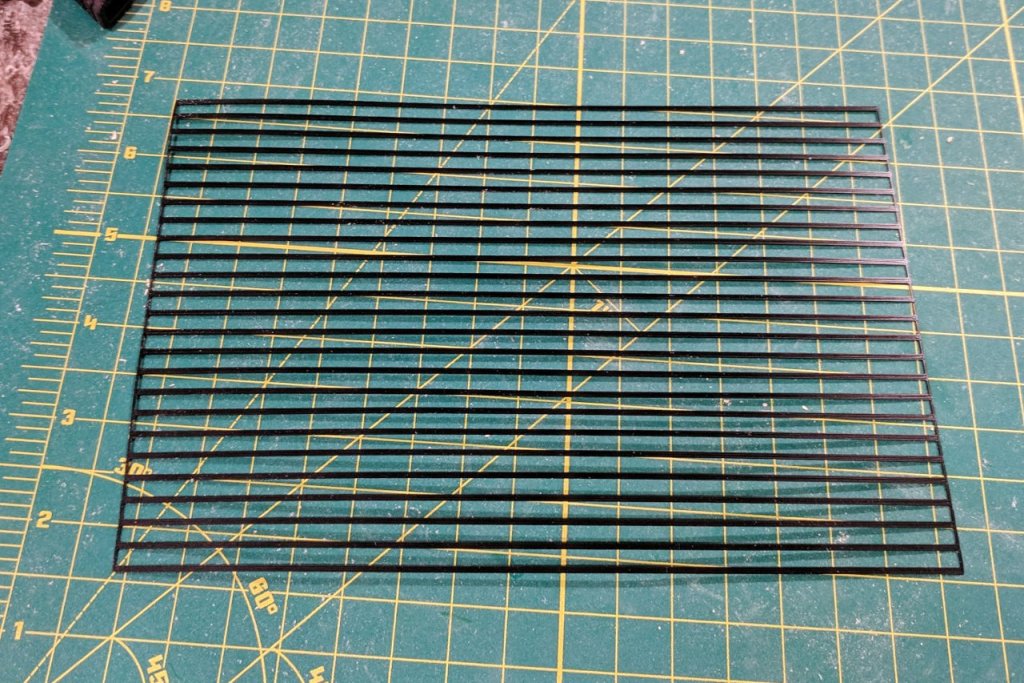
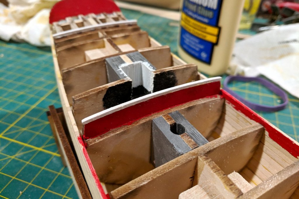
It's time to think about the deck. Here is my foot, taking a very scientific measurement. The deck planks, caulking included, are a little over two shoe lengths. That's... um, (multiply by the scaling factor, carry the three), how wide? Better yet, I'll consult the appendix in the Schooner Sultana book. The appendix says the deck planks are 5 inches wide. At 1:64 scale, that's about 2mm. I'll be using 1/16" x 1/16" strip for the deck planks, which is close enough. A few other things to note: the inner bulkwarks, transom, and other surfaces are painted red. At all deck level changes, there is a white strip. There is a deck plank along the center line, rather than planks on either side of the center line. I have checked multiple pictures and confirmed that, even at the longest part, all deck planks are continuous; there are no breaks. That means there will be no butt-shift pattern. Lastly, note how thick and dark the caulking is. I have added red paint where needed and white strips at the edges of each deck. The white strips are 1/16" and the bulkheads they lay on are 1/8", so there is still enough surface for the ends of the deck planks to lay on. I want to replicate the thick, dark caulking between the deck planks. Imagine if I had strips of black plastic that were as thick as the decking strips and just wide enough to create a nice thick black line between planks. About .4mm will do. Anything I imagine I can model in Fusion 360. And after loading black filament, it's 3D printed. Starting to plank the deck. My procedure is to cut some 1/16" x 1/16" strip to size, and cut some black plastic to match. I add glue to the strip and put it almost in place, then carefully slip the plastic into the gap. Then push the plank firmly into place. The rough edge at the front will be filed down to a nice curve to accept the bulwarks, which will be added later. The forecastle is done. Starting to plank the main deck.


- 222 replies
-
- 4
-
-
- sultana
- model shipways
- (and 1 more)
-
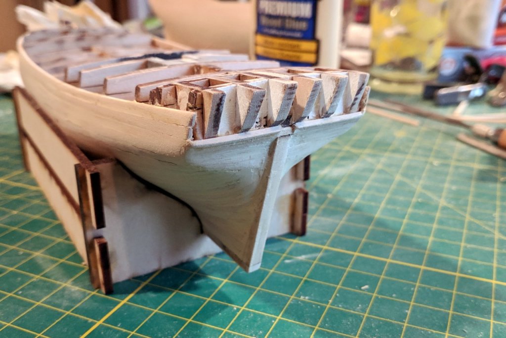
Attaching the transom. The inner part first. And the other two parts. I painted ahead of time because it would be too difficult to get a brush into the recessed areas. The pieces were attached in a staggered fashion so that the top surface would be horizontal. This will allow the trim piece to sit properly on top. The view from the back. 1/16" x 1/16" strips were added to fill in the remaining space. A little more work is needed to smooth out the area just below the transom piece.
- 222 replies
-
- 3
-
-
- sultana
- model shipways
- (and 1 more)
-
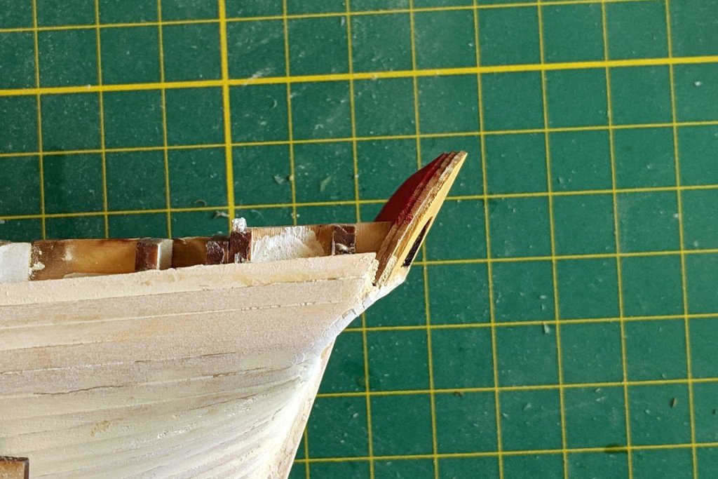
I don't recall having this issue, but looking at the pictures in my build log, the bottom of the transom piece and the deck beam piece were of equal width. So sanding it down looks like the right thing to do.
- 68 replies
-
- 3
-
-
- virginia 1819
- artesania latina
- (and 1 more)
-
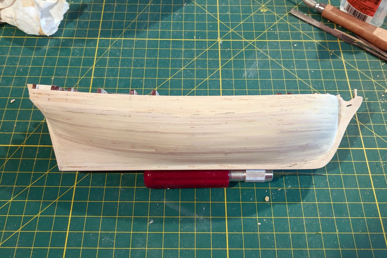
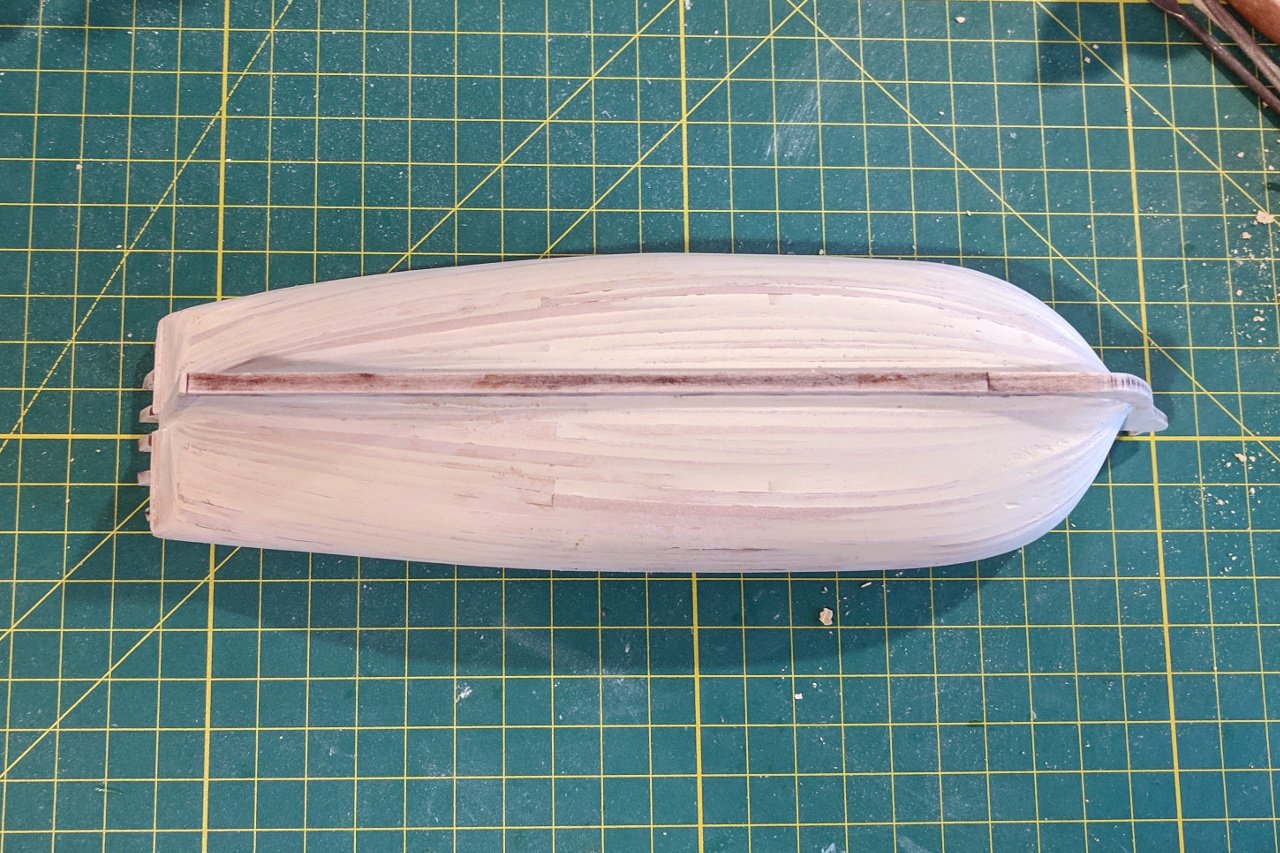
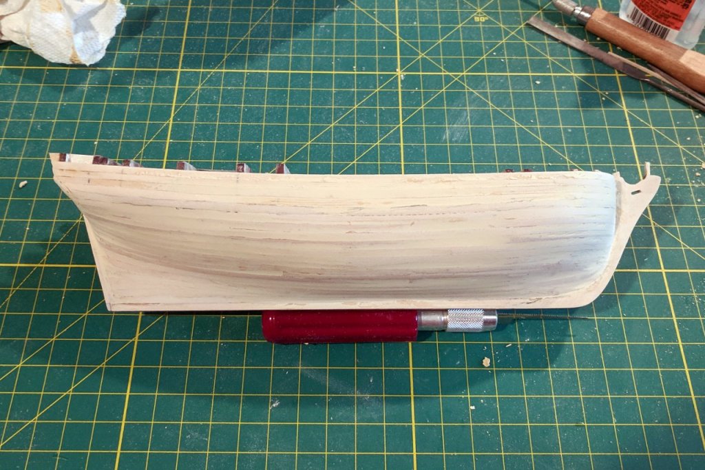
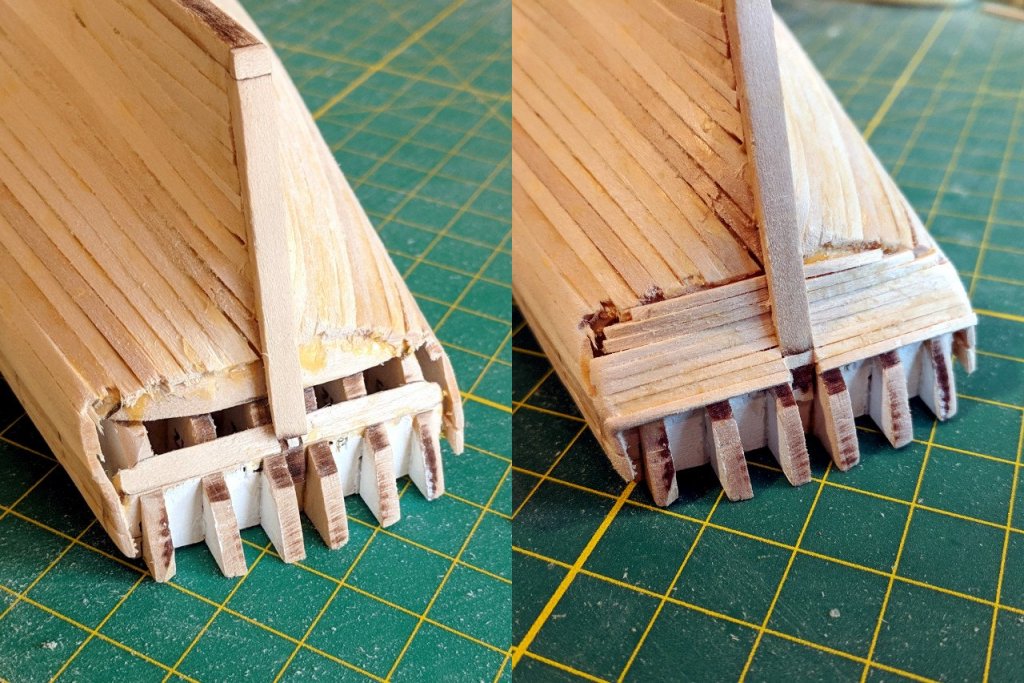
I ended up applying wood filler and sanding at this point. First, I was worried that the rough handling during sanding might damage the transom pieces if I attached them first. And second, I was just impatient to get the nice, smooth hull that I hoped for.

- 222 replies
-
- 6
-
-
- sultana
- model shipways
- (and 1 more)
-
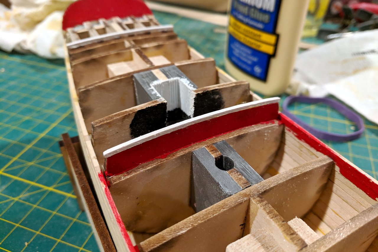
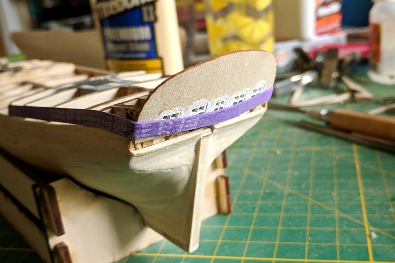
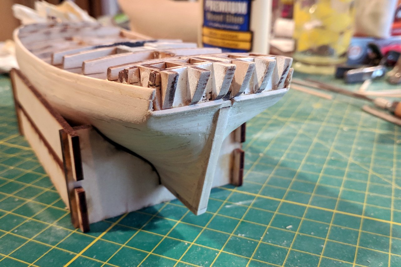
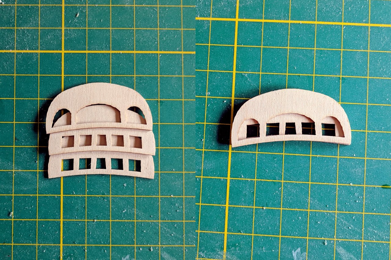
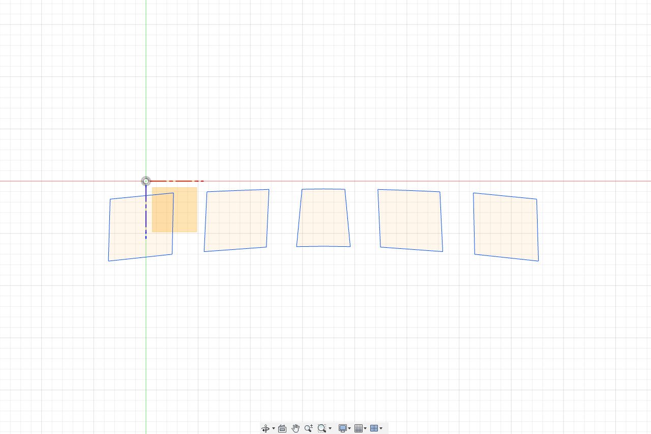
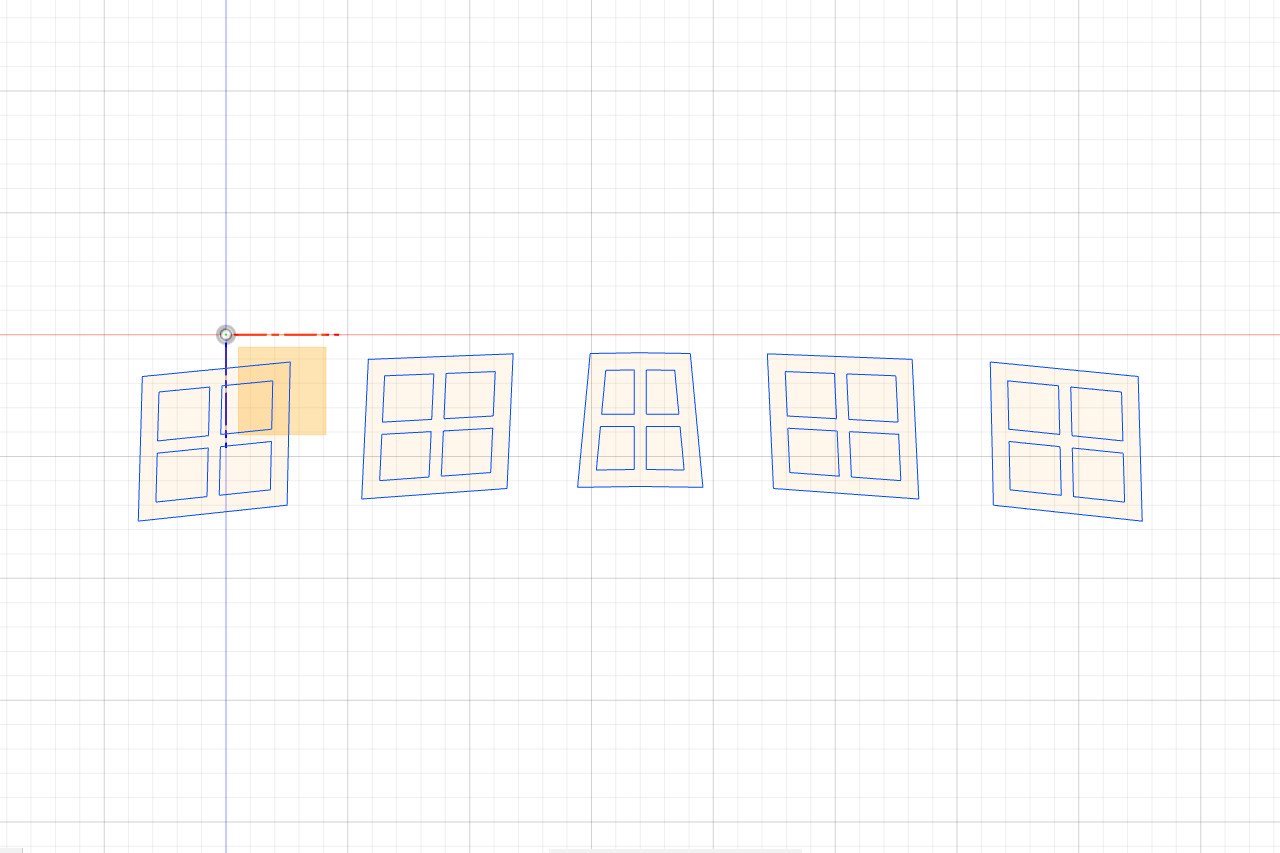
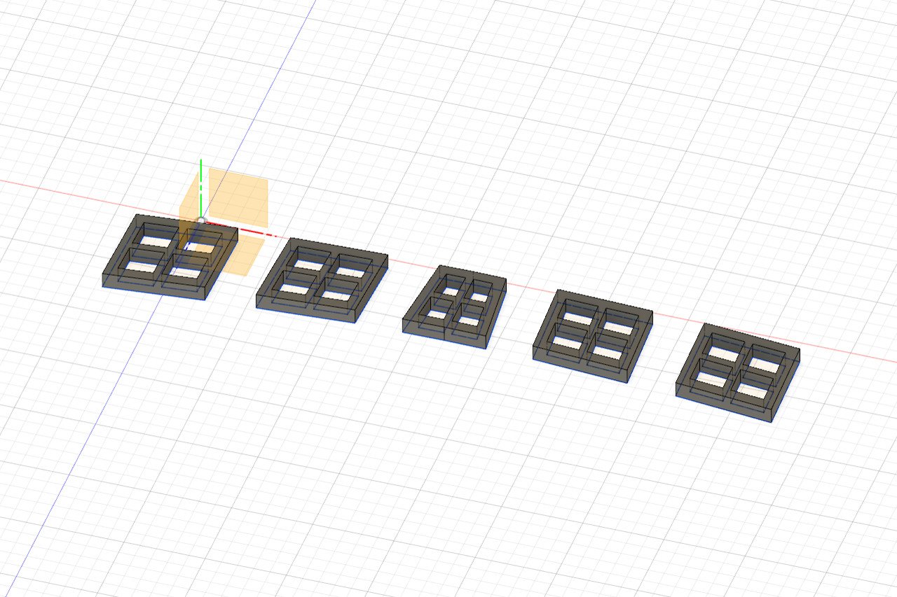
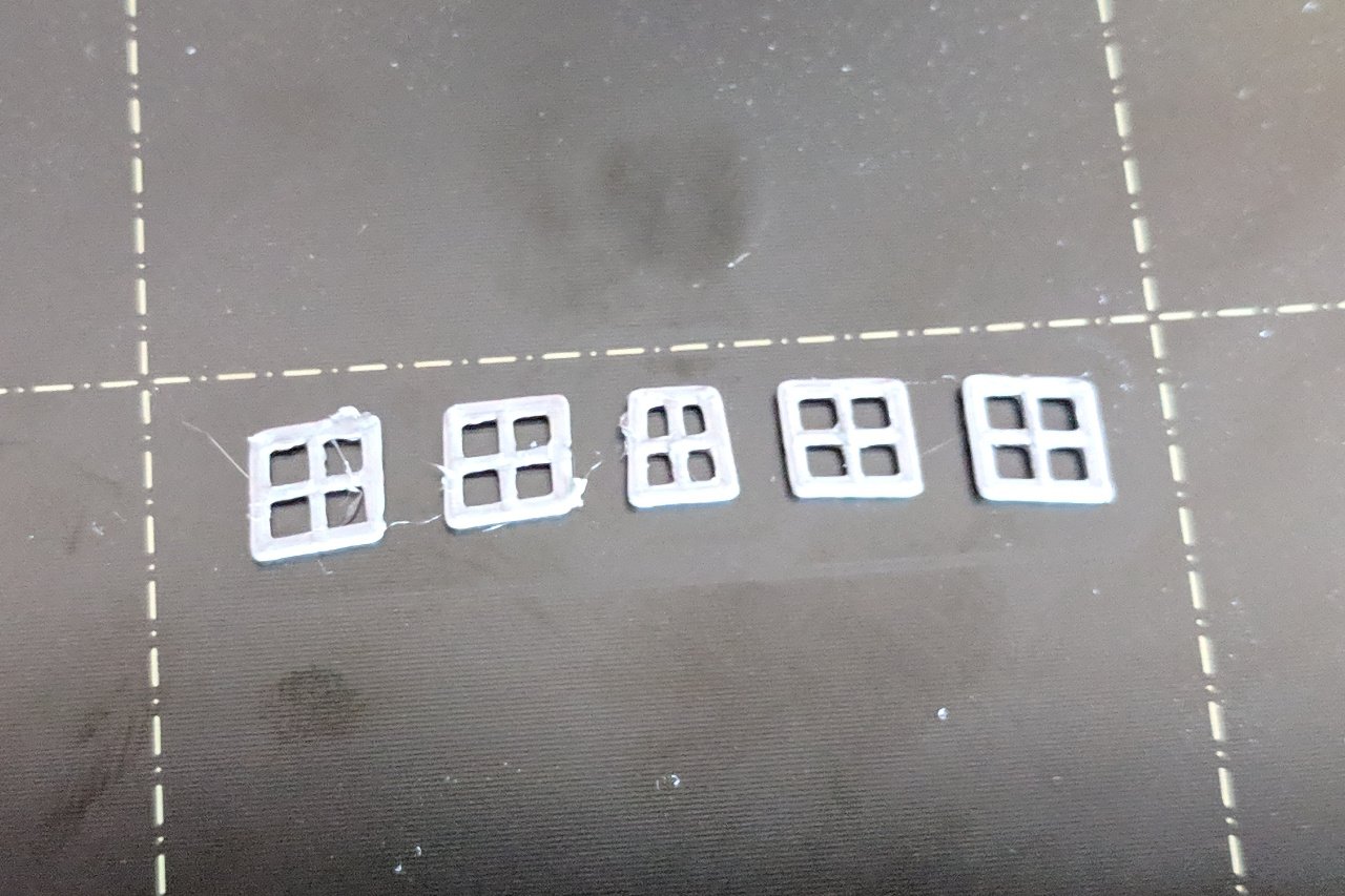
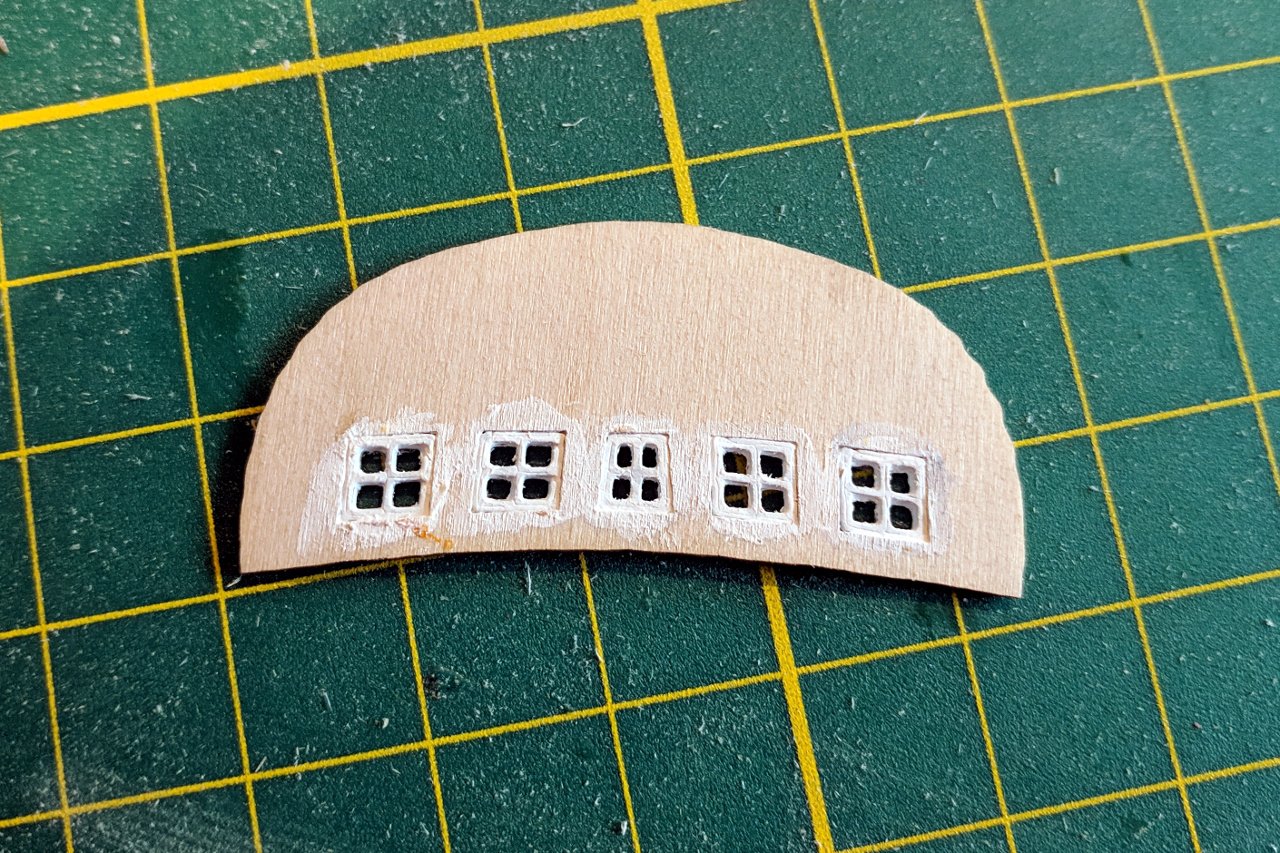
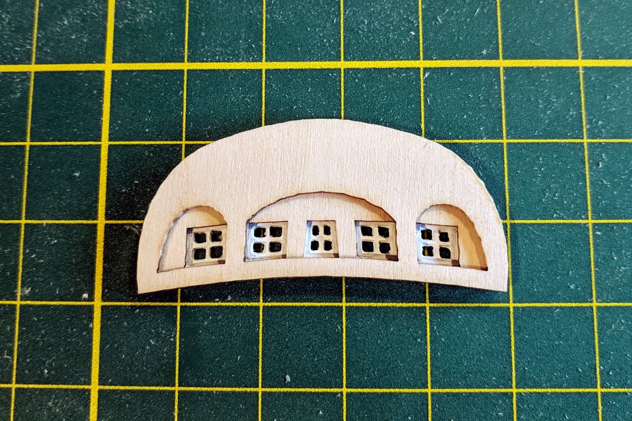
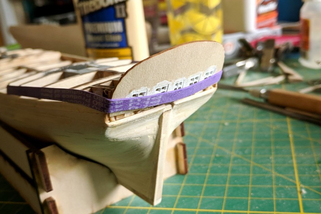
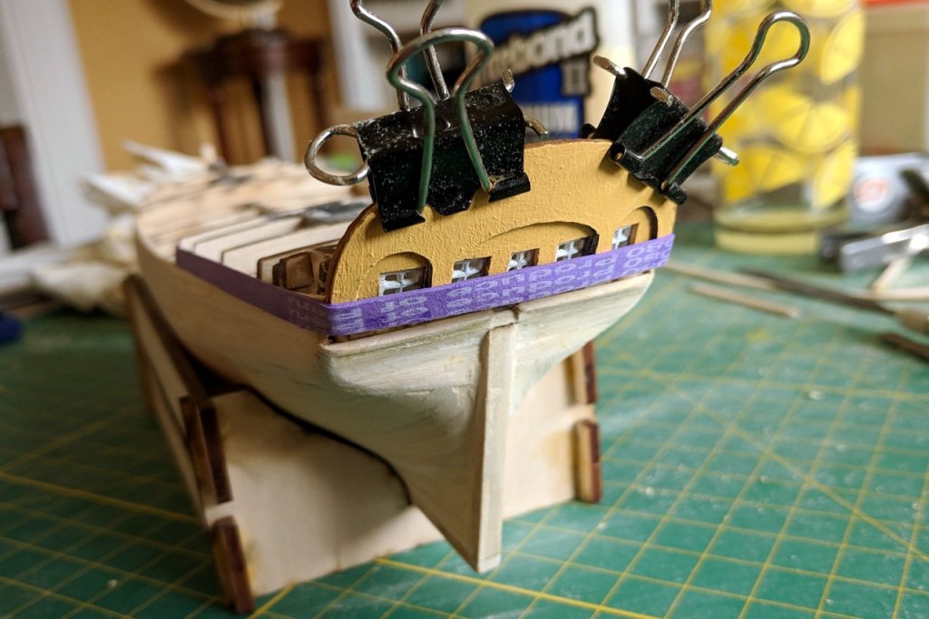
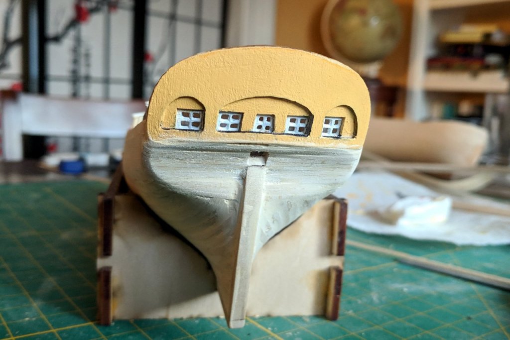
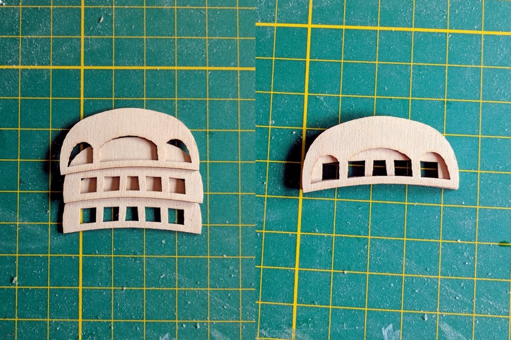
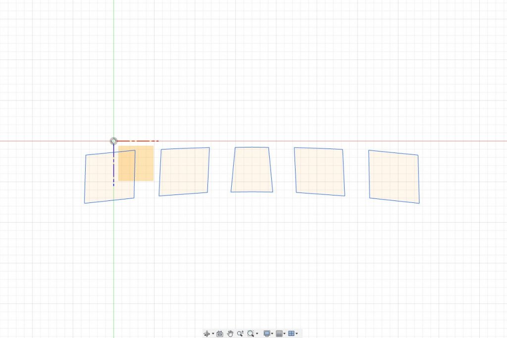
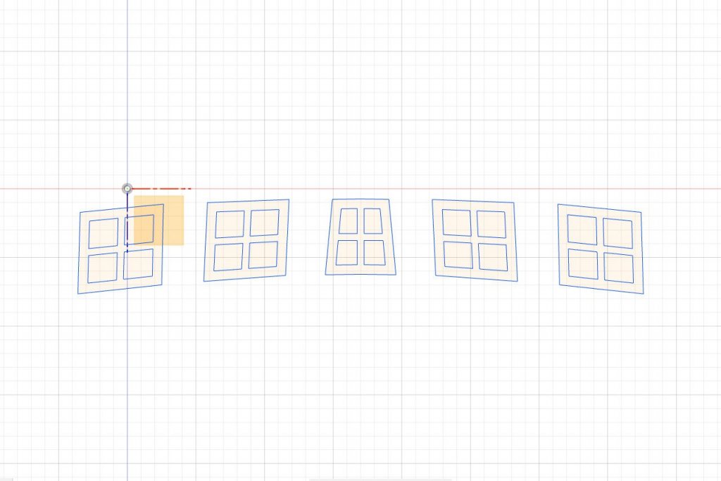
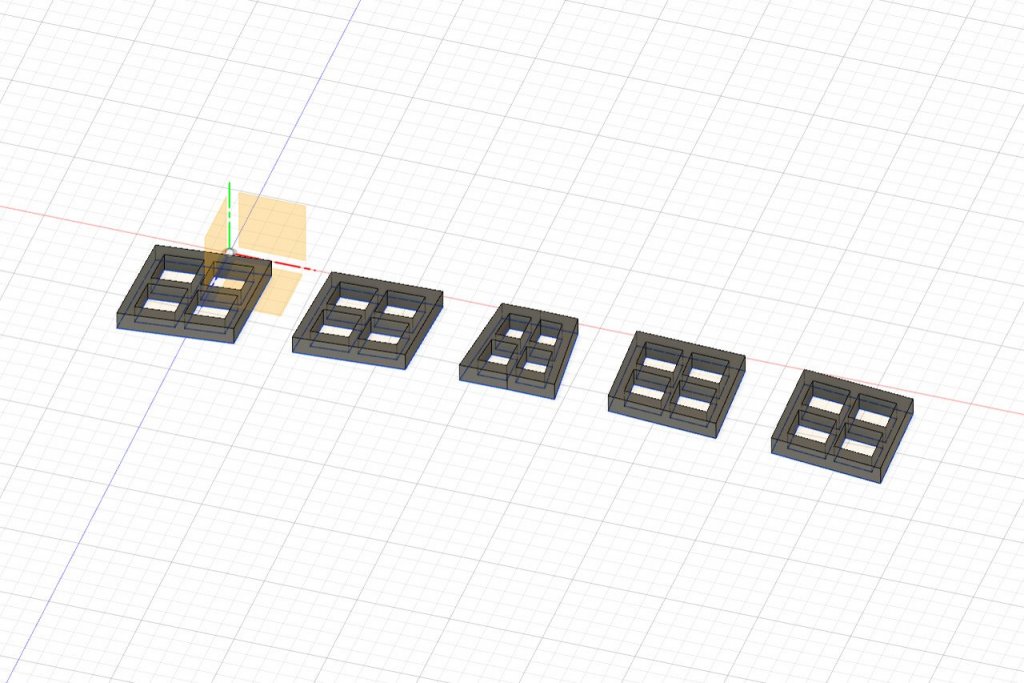
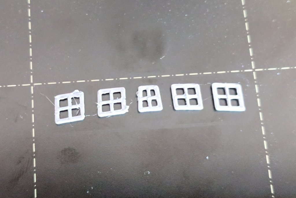
Using 1/16" x 1/16" strips, I have filled in part of the counter. It's clear that I'll need some filler to patch the gap between the hull planks and the counter planks. Next, I want to glue on the transom end pieces and then I will be able to fill in the remaining space. My transom end pieces are three laser cut pieces, 1/32" thick, which bend easily. The three pieces will be sandwiched together to form the transom shape with its recesses. However, before I attach those pieces, I should put the windows in place. Here are the window shapes in Fusion 360. Panes for the windows are added. And the shapes are extruded. Saved and 3D printed. The pieces are glued in and painted white. And here is how it looks all assembled.


- 222 replies
-
- 3
-
-
- sultana
- model shipways
- (and 1 more)