HOLIDAY DONATION DRIVE - SUPPORT MSW - DO YOUR PART TO KEEP THIS GREAT FORUM GOING! (Only 72 donations so far out of 49,000 members - Can we at least get 100? C'mon guys!)
×


SardonicMeow
-
Posts
333 -
Joined
-
Last visited
Content Type
Profiles
Forums
Gallery
Events
Everything posted by SardonicMeow
-
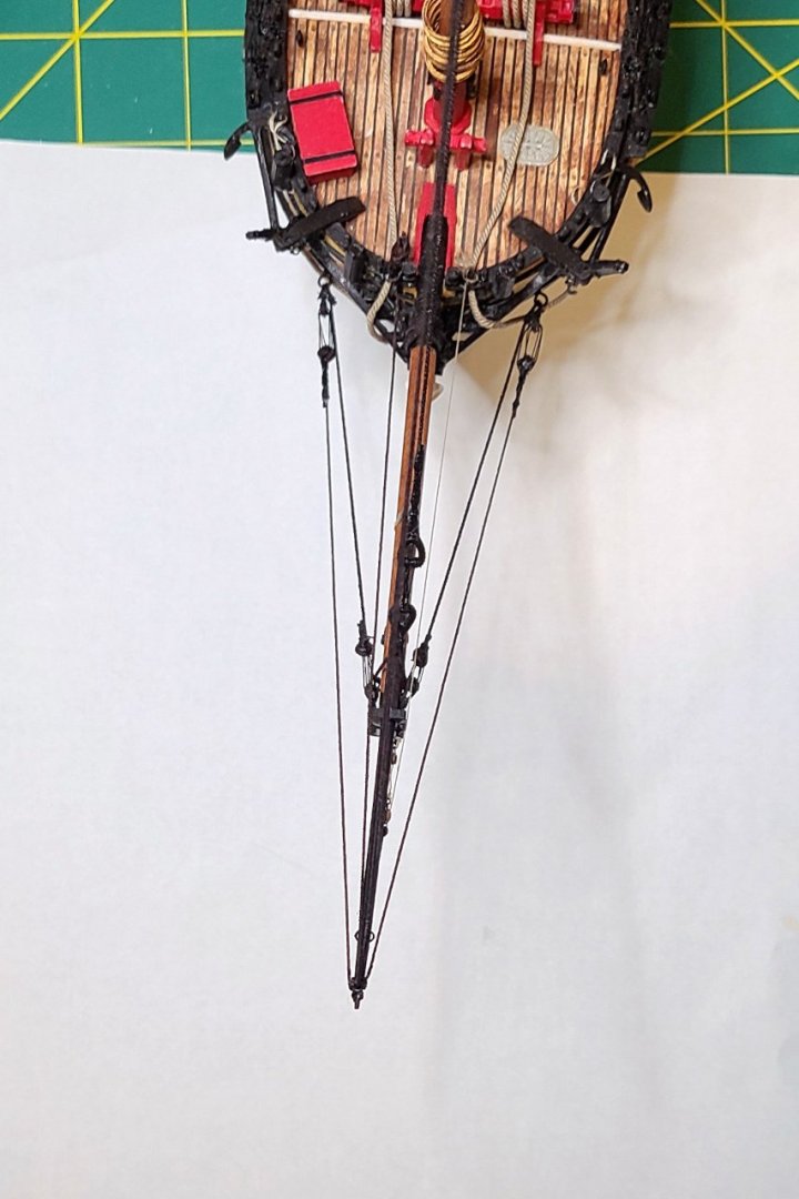
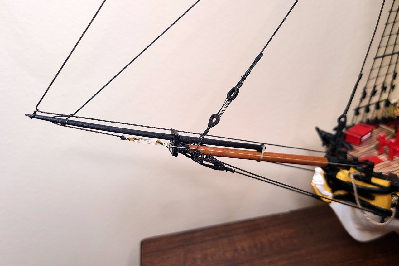
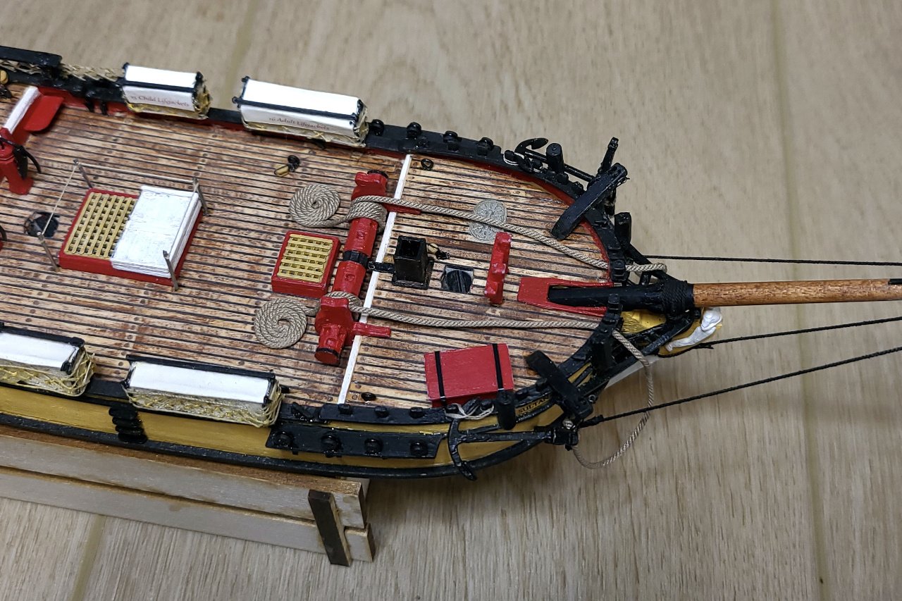
 Here are the jibboom guys hanging free with deadeyes at the end. The deadeyes were linked with deadeyes previously attached to eyebolts at the bow. Here's a neat view of everything from above. The main stay and main topmast stay were added each with a pair of hearts. Next time: adding lots of blocks, probably.
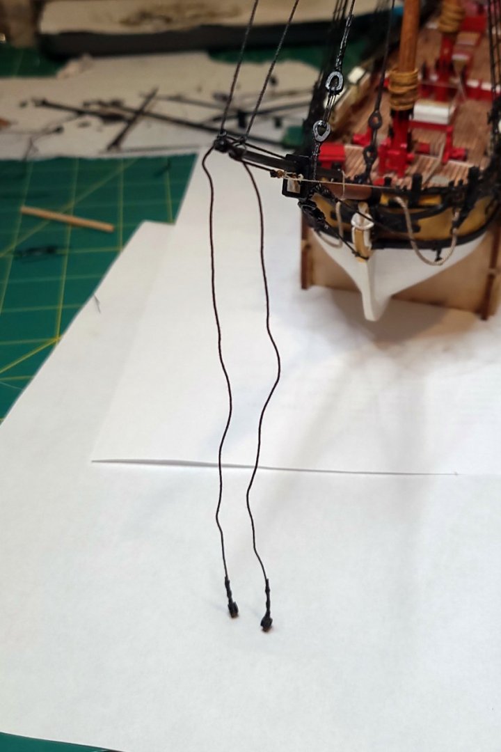
- 222 replies
-
- 6
-

-
- sultana
- model shipways
- (and 1 more)
-
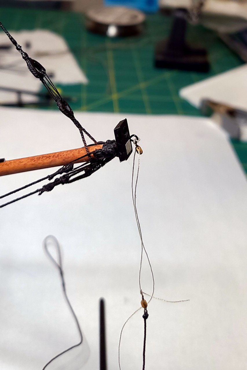
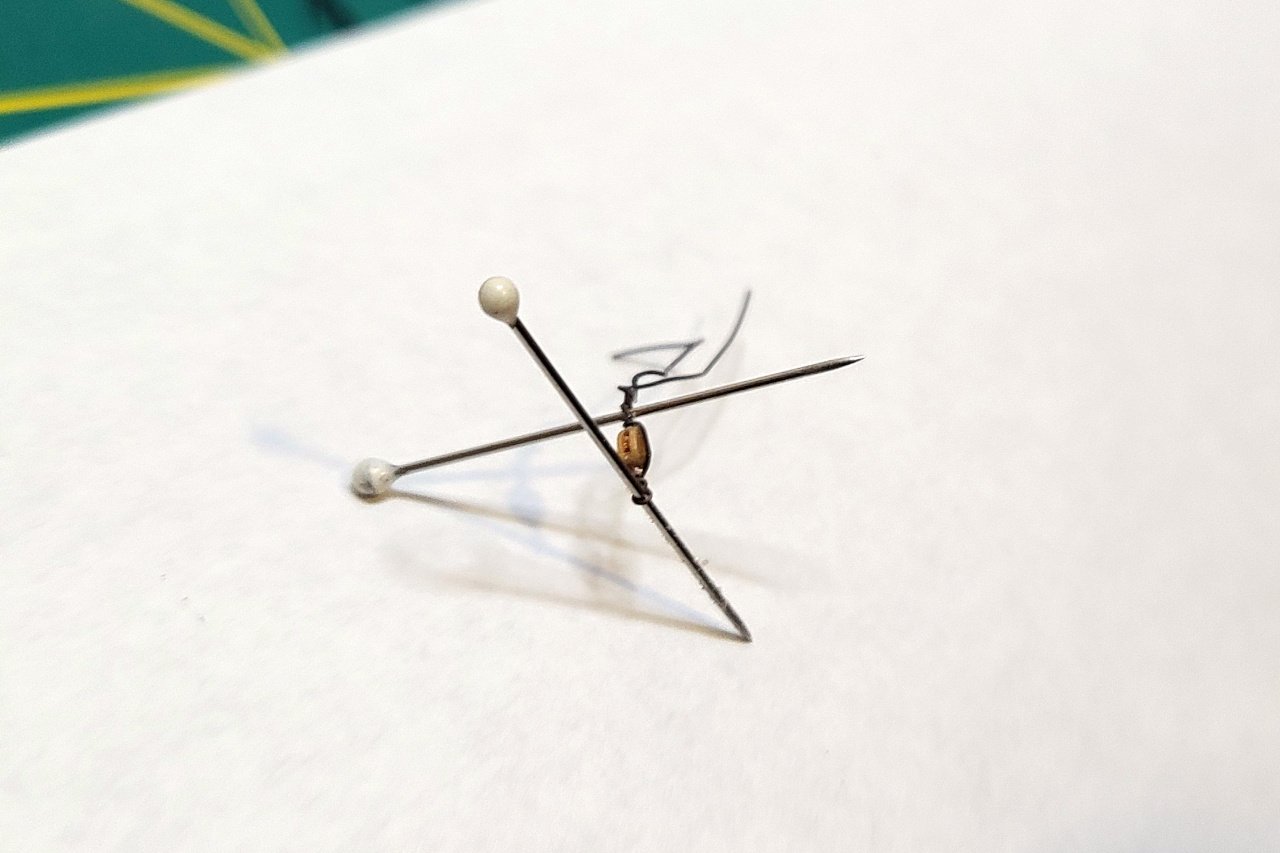
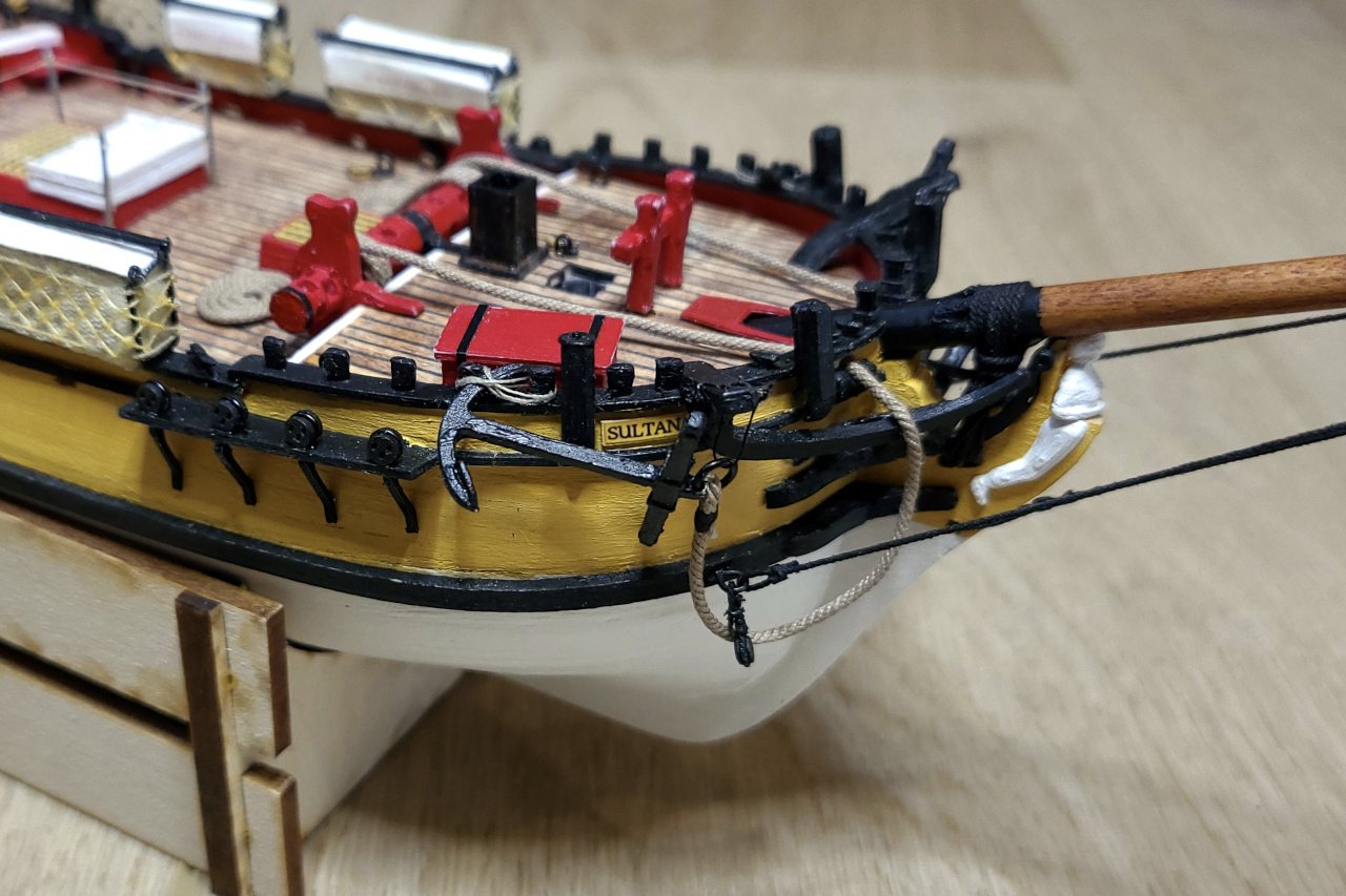
Wire is wrapped around a pin, around a tiny 2mm block, and then around another pin to give me two loops at either end of the block. Glue was applied and excess wire was cut off. The outer jibstay was threaded through the jibboom with the block at one end and a seized loop at the other end. Before the jibboom was put into place, the block at the end of the jibstay and the block already placed at the end of the bowsprit were threaded. Finally, the jibboom was glued into place and the line between the blocks was tightened. The fore topmast was glued on and the fore topmast stay was run from the top of the topmast and through the loop at the end of the jibboom. There are a few more details to do around the bowsprit and jibboom but the majority is complete. Unfortunately, the tightening of subsequent stays has caused the forestay to become slack. I'm hoping that the mainstay will pull the foremast back a little bit and correct that.

- 222 replies
-
- 6
-
-

-
- sultana
- model shipways
- (and 1 more)
-
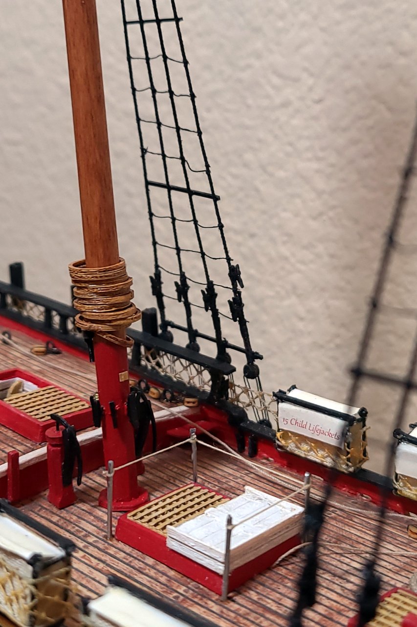
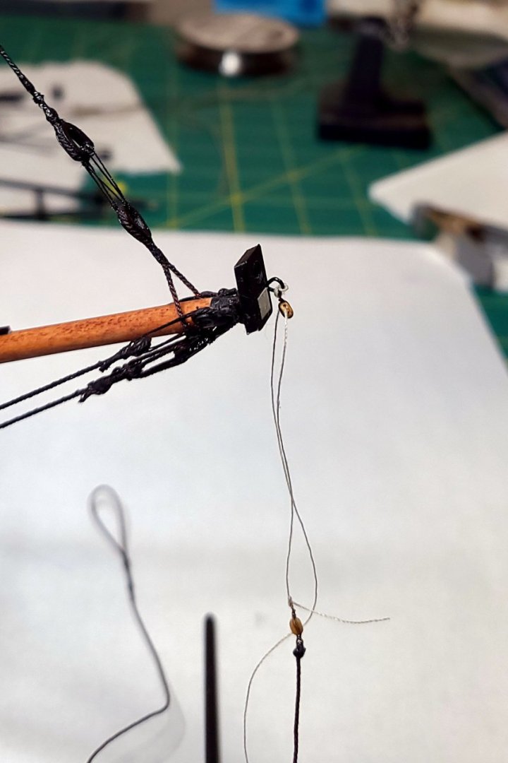
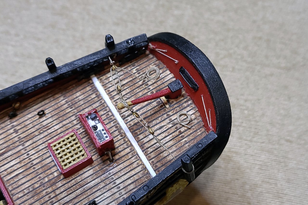
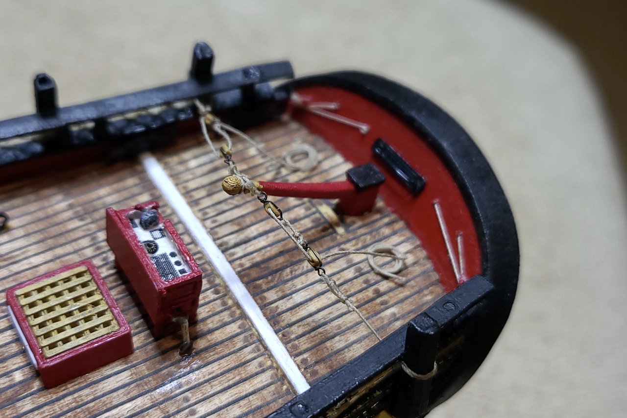
Thanks, Matt. I'm definitely going to push through to the end. Glad you're following along again. So, I said that the shrouds were done, but I forgot about the cleats. As before, I laid the model on its side, and was able to glue the cleats simply by applying glue and laying the cleats on the shrouds. Afterwards, I used some thread to reinforce each cleat. One heart for the forestay was already attached to the bowsprit several build log updates and four years ago. The forestay was seized to the foremast and the hearts were threaded. It took multiple attempts until I was able to get the pair of hearts oriented the way I wanted. The heart for the inner jibstay was also attached to the bowsprit. For now, it's just dangling loose on the bowsprit.
- 222 replies
-
- 4
-
-
- sultana
- model shipways
- (and 1 more)
-
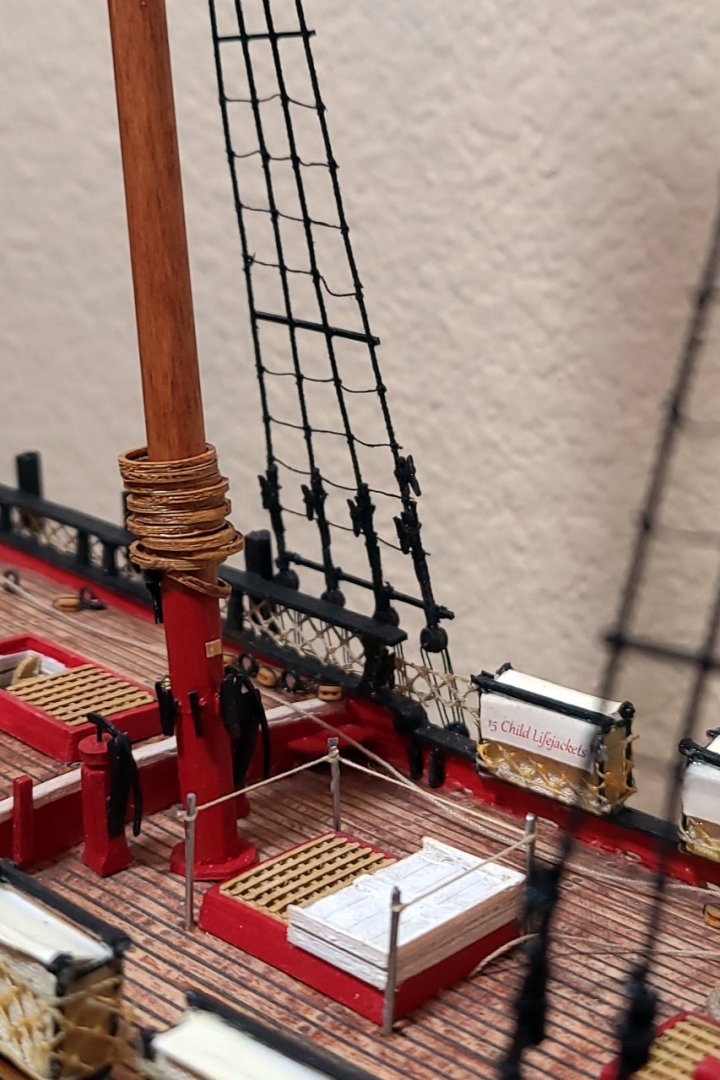
There are poles or rungs (not sure what the right term is) where every fifth ratline should be. These were added by laying the ship on its side and gluing black plastic strips in place. With that, the ratlines are truly complete.
- 222 replies
-
- 6
-
-
- sultana
- model shipways
- (and 1 more)
-
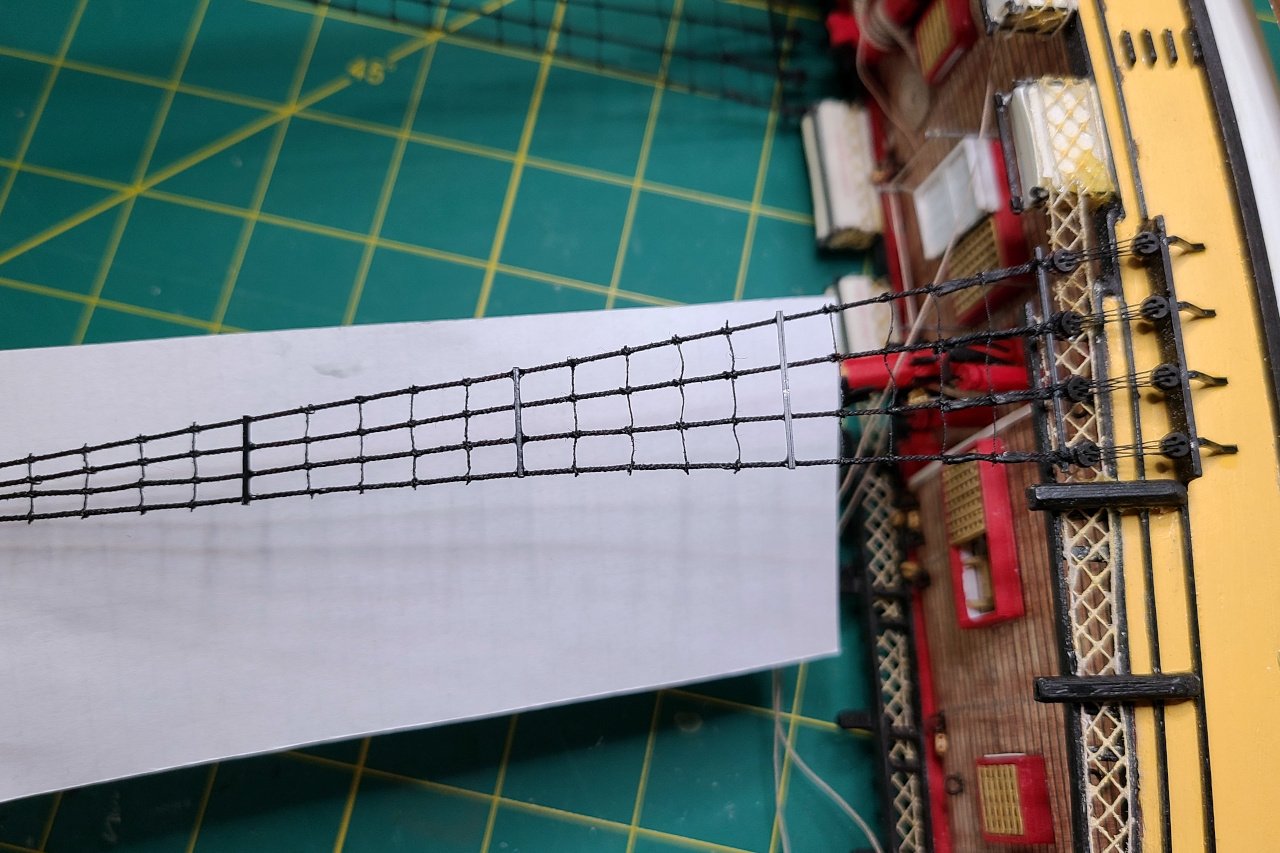
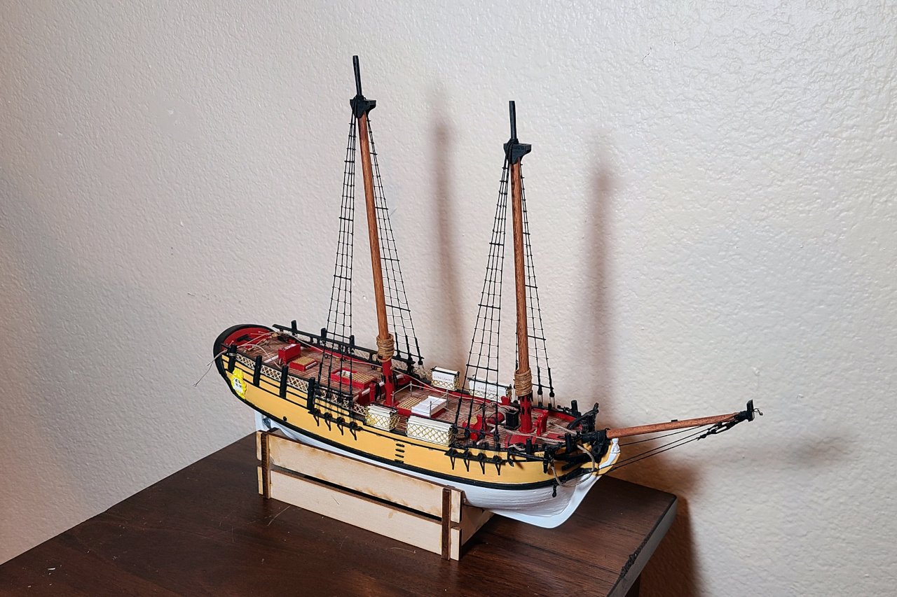
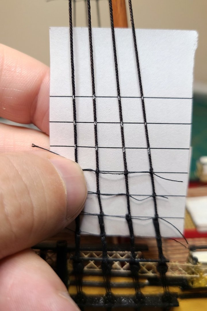
The ratlines are complete. Quite a time-consuming operation. It took me... wow. What year is this? As shown below, I printed out a spacing guide and used chalk to mark the location of each knot on the shrouds. Here's a shot with all the ratlines done. Note the gaps in the ratlines. Those will be addressed in the next update.
- 222 replies
-
- 5
-
-
- sultana
- model shipways
- (and 1 more)
-
Thanks for clarifying, Eamonn. I think the right name for the sail you're describing is the fore staysail. Looking at your (really lovely) pictures of the Ballahoo in profile, there is a very short distance between the fore mast and fore stay, so I assumed there would be no fore staysail. But it's certainly possible. As always, I look forward to seeing your progress.
- 1,039 replies
-
- 3
-
-
- ballahoo
- caldercraft
- (and 2 more)
-
I've been spending a little while looking at your diagram. The only major issue I see is the foresail sheet. Perhaps you intended to assign that to the aft pinrails, but put it on the fore pinrails by mistake? Also, I don't see what a foresail halyard would do, as the foresail can be raised and lowered with the gaff peak / throat halyards.
- 1,039 replies
-
- 2
-
-
- ballahoo
- caldercraft
- (and 2 more)
-
Hi, Max. If you have discovered any new techniques in Fusion 360, please share. As for including pictures, start a reply, then click on the "choose files" link at the bottom where it says "Drag files here to attach, or choose files..." Move your cursor into the position in your text where you want the image to appear, then click the plus sign on the image. For more help, look in the "How to use the MSW forum" forum.
-
Very interesting to see a different take with the painted hull, coppered bottom, and modified anchors. Thanks for sharing.
-
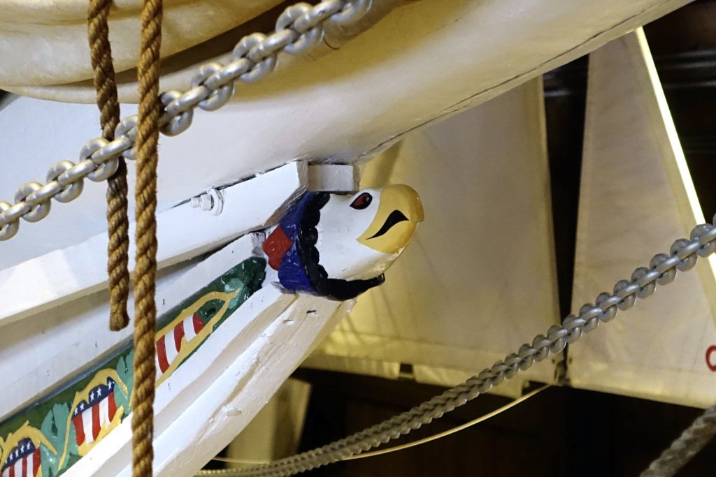
Here's a picture I took of the figurehead on the E. C. Collier. I love how yours captures the same feel and style of this and other skipjack figureheads I've seen.
- 82 replies
-
- 8
-
-
- skipjack
- wye river models
- (and 2 more)
-
Nope. The mistake is not yours, it's Artesania Latina's. You're finding flaws in the kit that every other builder also encounters. I like your fix for the rudder. I think it'll look better than the correction I made to mine. To my eye, your stem still looks a little low. You'll need the bowsprit at an angle such that a line from the end of the bowsprit running aft towards the bow will be able to go over the bow railing.
-
Hull modeling with Blender
SardonicMeow replied to SardonicMeow's topic in CAD and 3D Modelling/Drafting Plans with Software
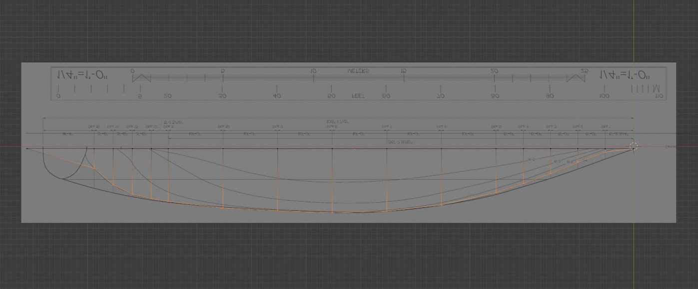
Yes, the horizontal lines are the waterlines. In the plans you posted, they are labelled F, G, H, and I in two of the three views. They are not labelled in the side view, but you can figure out which match the corresponding lines in the other drawings. To make the vertices match up to the lines, you'll need to subdivide the plane object to get the right number of lines, then slide the lines up, down, left, or right to match up with the lines in the plans. -
Hull modeling with Blender
SardonicMeow replied to SardonicMeow's topic in CAD and 3D Modelling/Drafting Plans with Software
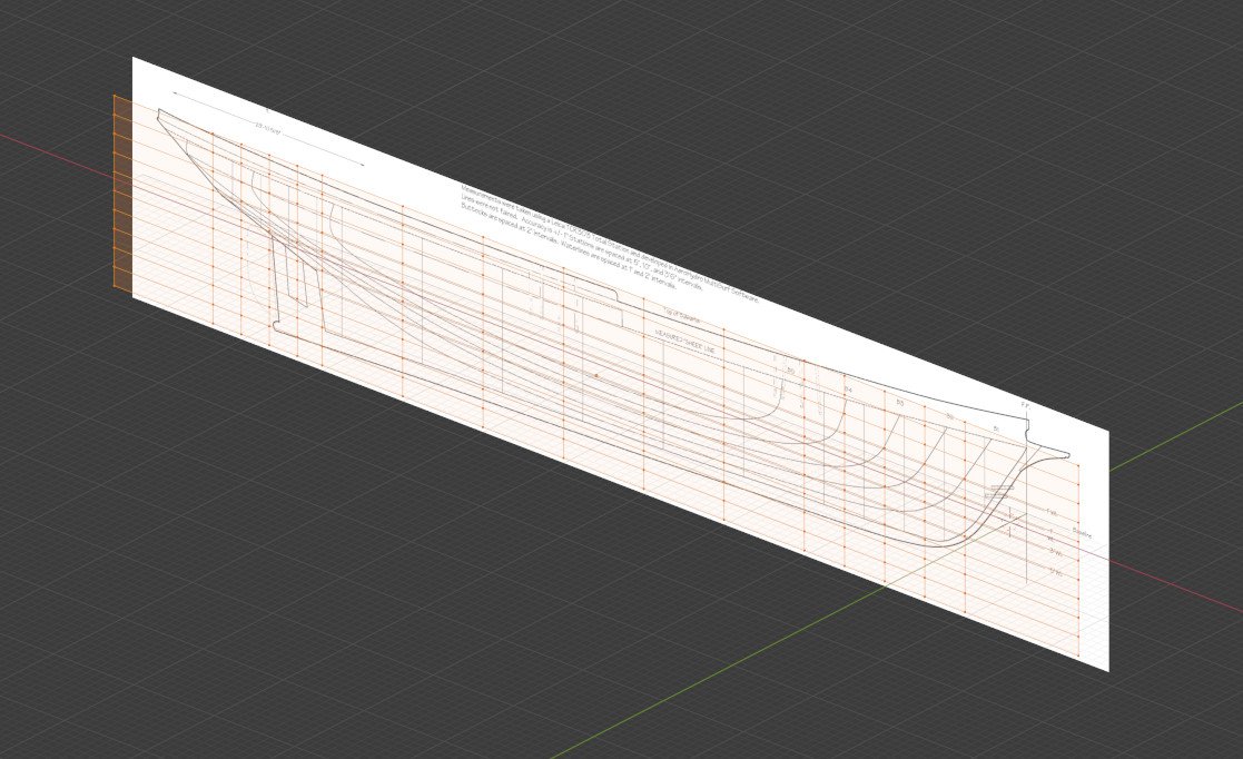
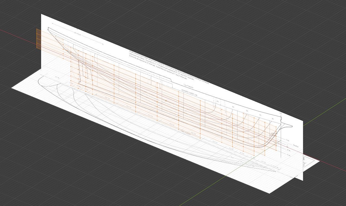
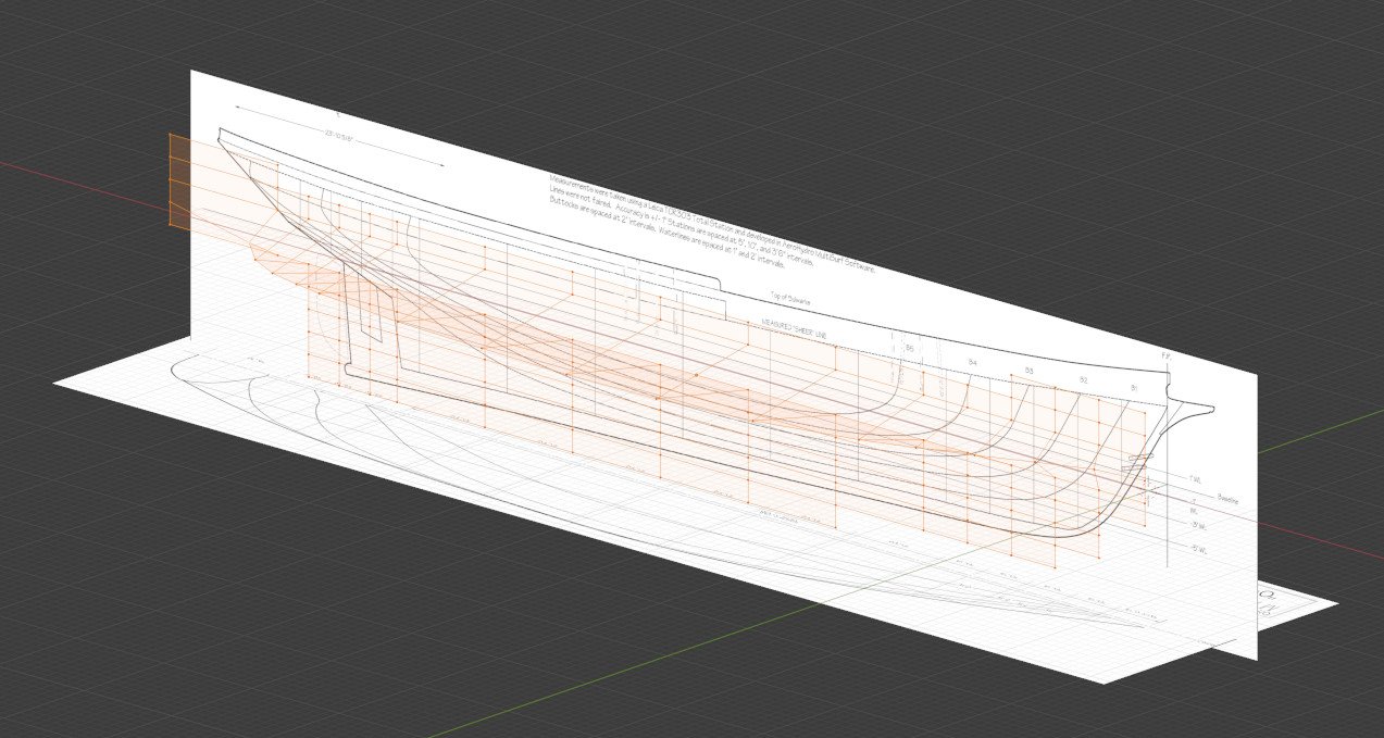
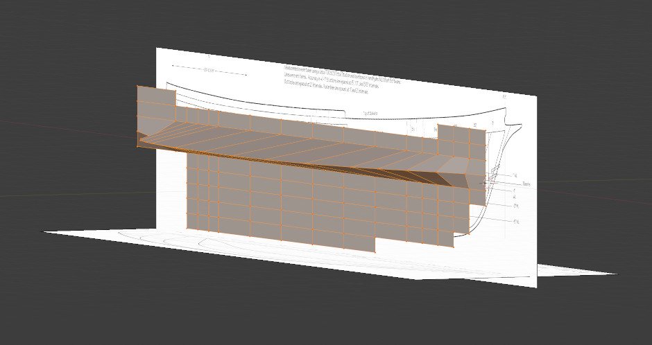
Ok. You're asking about the waterlines. On the plans that you posted, the waterlines are marked F, G, H, and I. These lines appear as straight lines on the first two pictures and are curved in the view from above. In my procedure, I create a Blender plane and subdivide it so that it matches the way the lines are arranged on the plan. Here is the side view of the plans I used and below that the blender object. By subdividing it this way, there is a vertex at every intersection of each of the lines. Here is another view of the same. Notice that at the beginning, the object is flat. The vertices will need to be pulled out into the hull shape. Here is a similar view with the other plan image visible. Also, I have deleted some of the vertices that I know will be unused. At this point, to follow the curve of a waterline, you have to go along each vertex of the waterline and move them one by one outwards to match the line on the plans. This picture is the view from above after a single waterline has been completed. And here is the same from a different viewing angle. I have captured both a wireframe and solid view. You can see how the vertices for a single waterline have been pulled out to match the proper curve. To complete the hull, it's just a matter of repeating the same procedure for all the other lines. I hope that answers your question, but if not, let me know and I'll try to explain further.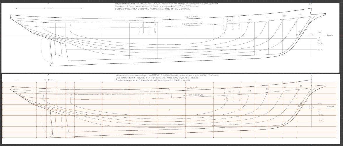
-
Hull modeling with Blender
SardonicMeow replied to SardonicMeow's topic in CAD and 3D Modelling/Drafting Plans with Software
I'm not sure what you mean by "match the curvature of the top view". Can you post a picture? -
Topsail schooner sail plans and rigging
SardonicMeow replied to Dr PR's topic in Masting, rigging and sails
Thank you for this, Phil. It's by far the best explanation of schooner rigging I've seen in one place. I do have a question about the jib / fore staysail inhaul. Wouldn't the more common arrangement be a downhaul that starts at the peak, runs down the stay (either through the hanks or free) to a block at the bowsprit, then to the bow? That would allow the sail to be entirely hauled down to the bowsprit, which isn't possible with a line attached at the tack. In this arrangement, the tack would simply be attached by a hook at a fixed point at the bowsprit cap or traveler. Maybe there would be an inhaul for a flying jib, but a downhaul + hooked tack for a jib or fore staysail?- 104 replies
-
- 3
-
-
- schooner rigging
- Topsail schooner
- (and 1 more)
-
Welcome to Model Ship World! You're off to a great start. The trenails on your deck are particularly well done. I look forward to seeing your further progress.
-
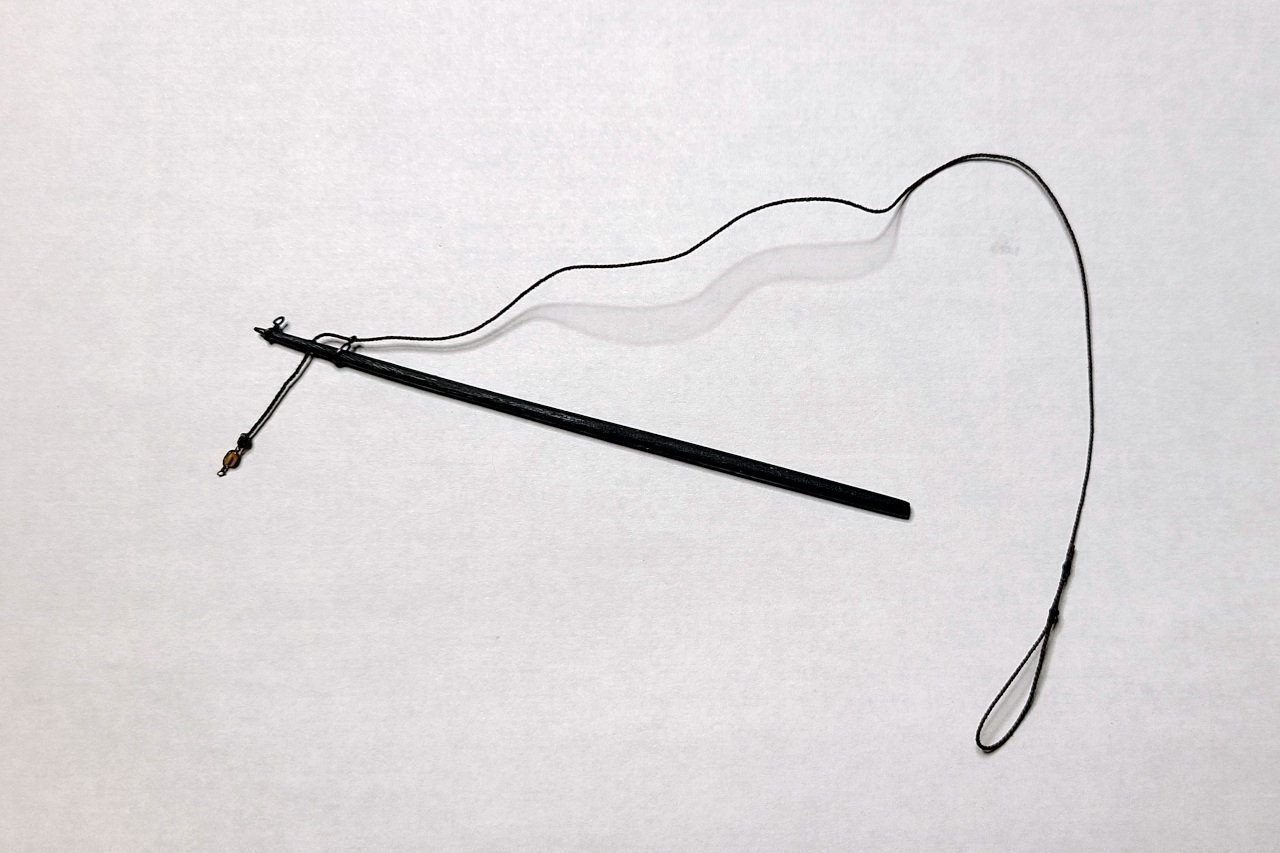
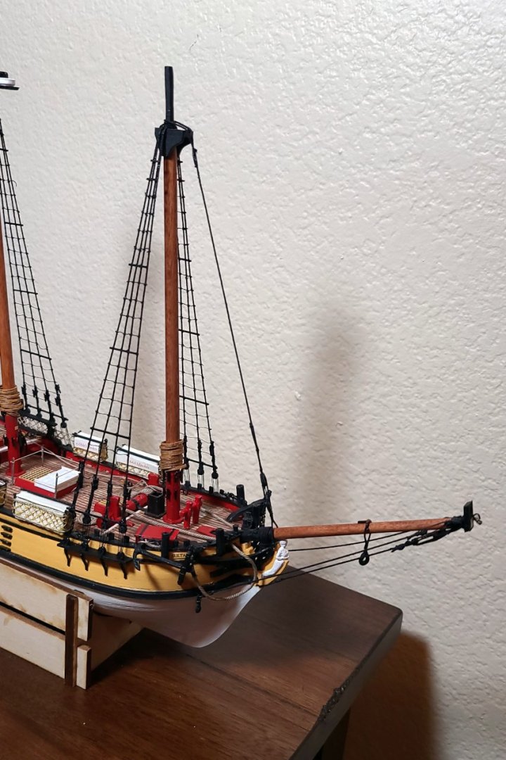
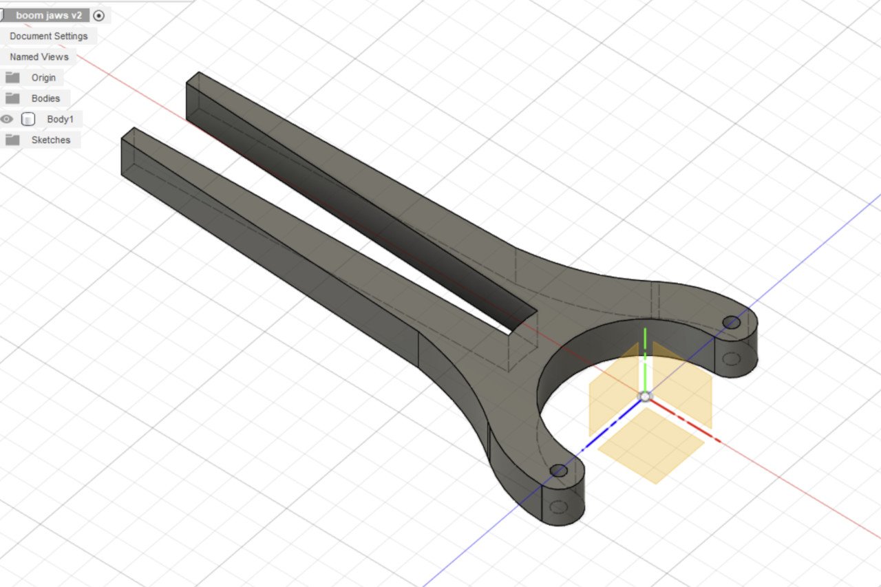
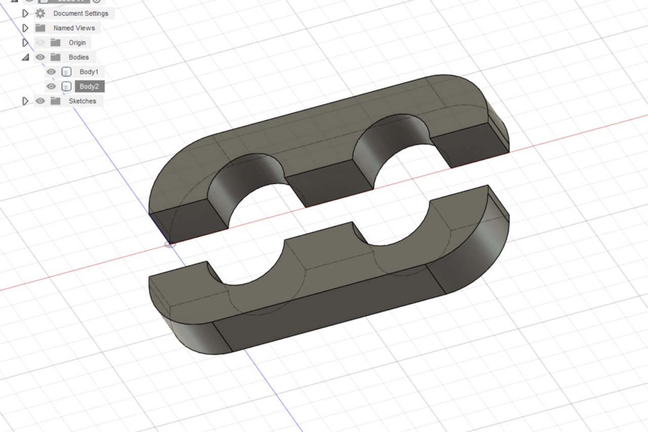
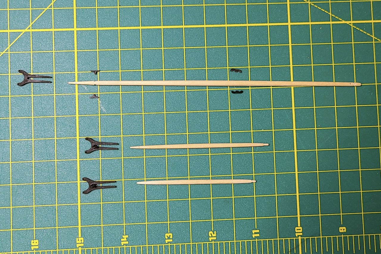
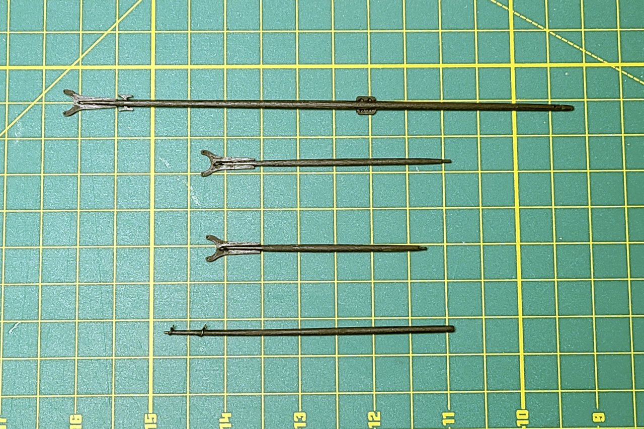
All the lanyards have been tightened and the sheer poles have been added. The next logical step is to run the ratlines. Yes, the ratlines are definitely the next thing that should be done. I have never done ratlines before. I'm really intimidated by the ratlines. An so, to avoid doing the ratlines, I worked on the boom and gaffs. First, of course, a few 3D printed parts. The dowels for the boom and gaffs were cut and formed. And all of it was glued together and painted black. Also pictured is the jib boom which I worked on a little while ago but haven't pictured here before.
- 222 replies
-
- 3
-
-
- sultana
- model shipways
- (and 1 more)
-
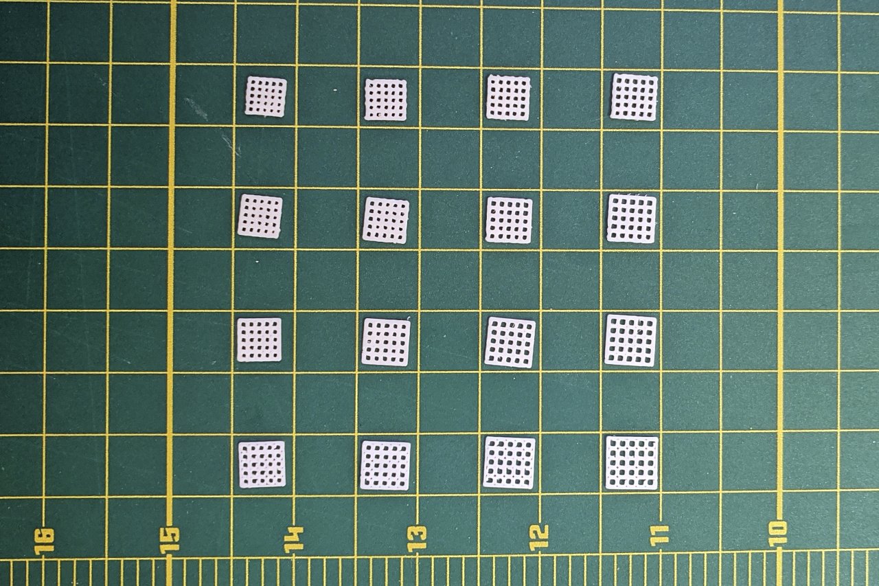
I haven't tried 3D printing blocks, but could give it a try. Now would be a good time, as I am actively avoiding the unpleasant task of tying ratlines on my Sultana. I did try printing deadeyes, but did not take any pictures at the time. From what I recall, deadeyes of diameter 4.5mm and larger were acceptable, but attempts at smaller diameters were malformed. Looking through my pictures, I did find the one below where I tried to produce grating. Left to right the hole size increases. Top to bottom the distance between holes increases. For the covers for the hatches on my Sultana, I used gratings with holes of 1.1mm per side and .7mm between holes.
-
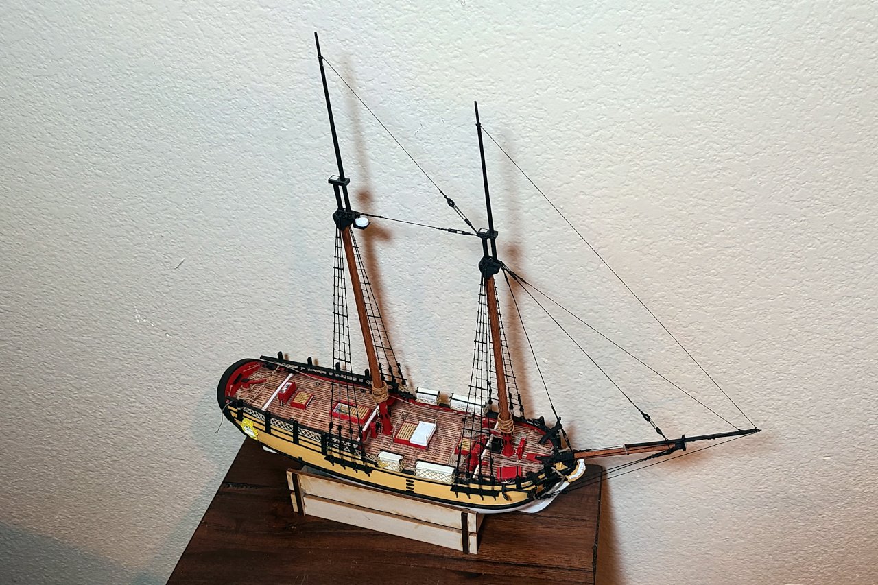
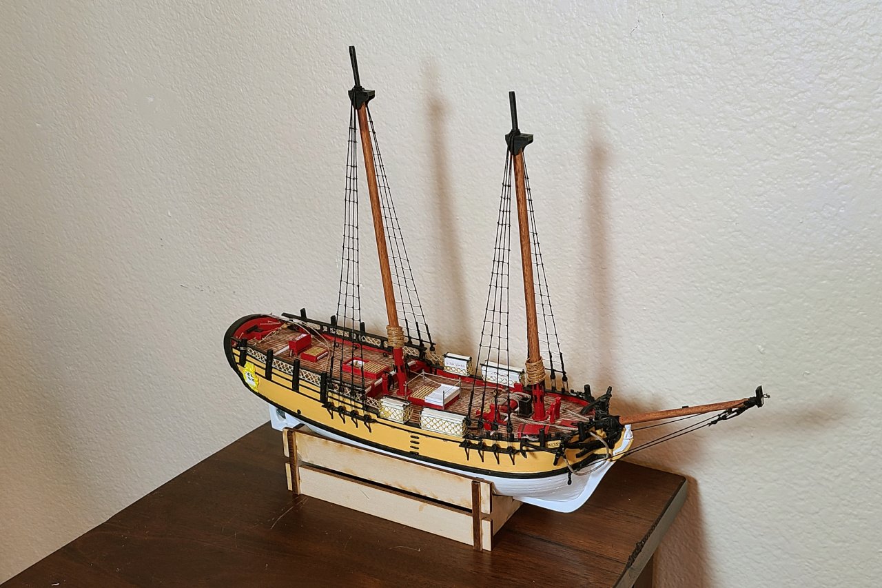
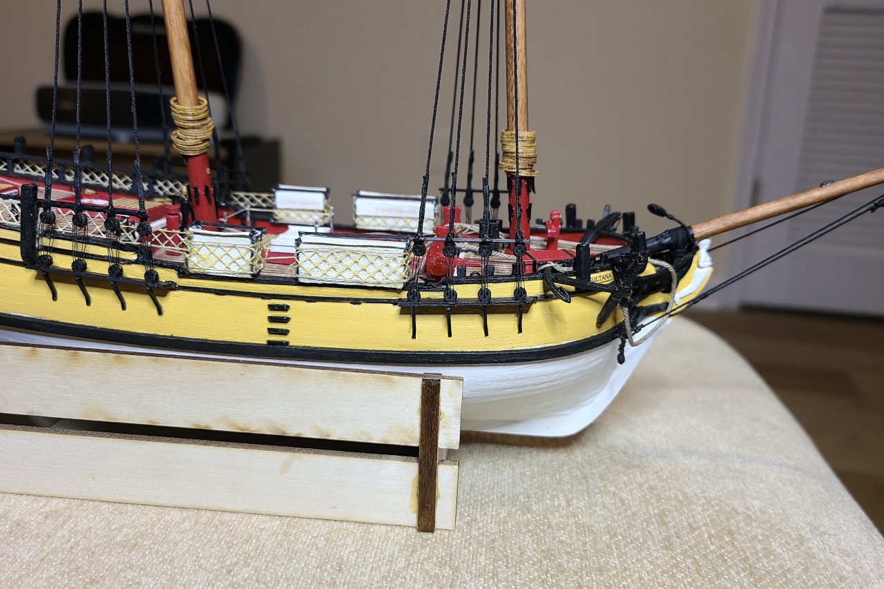
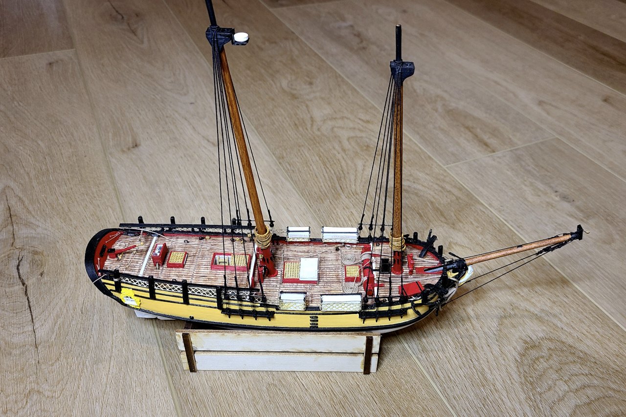
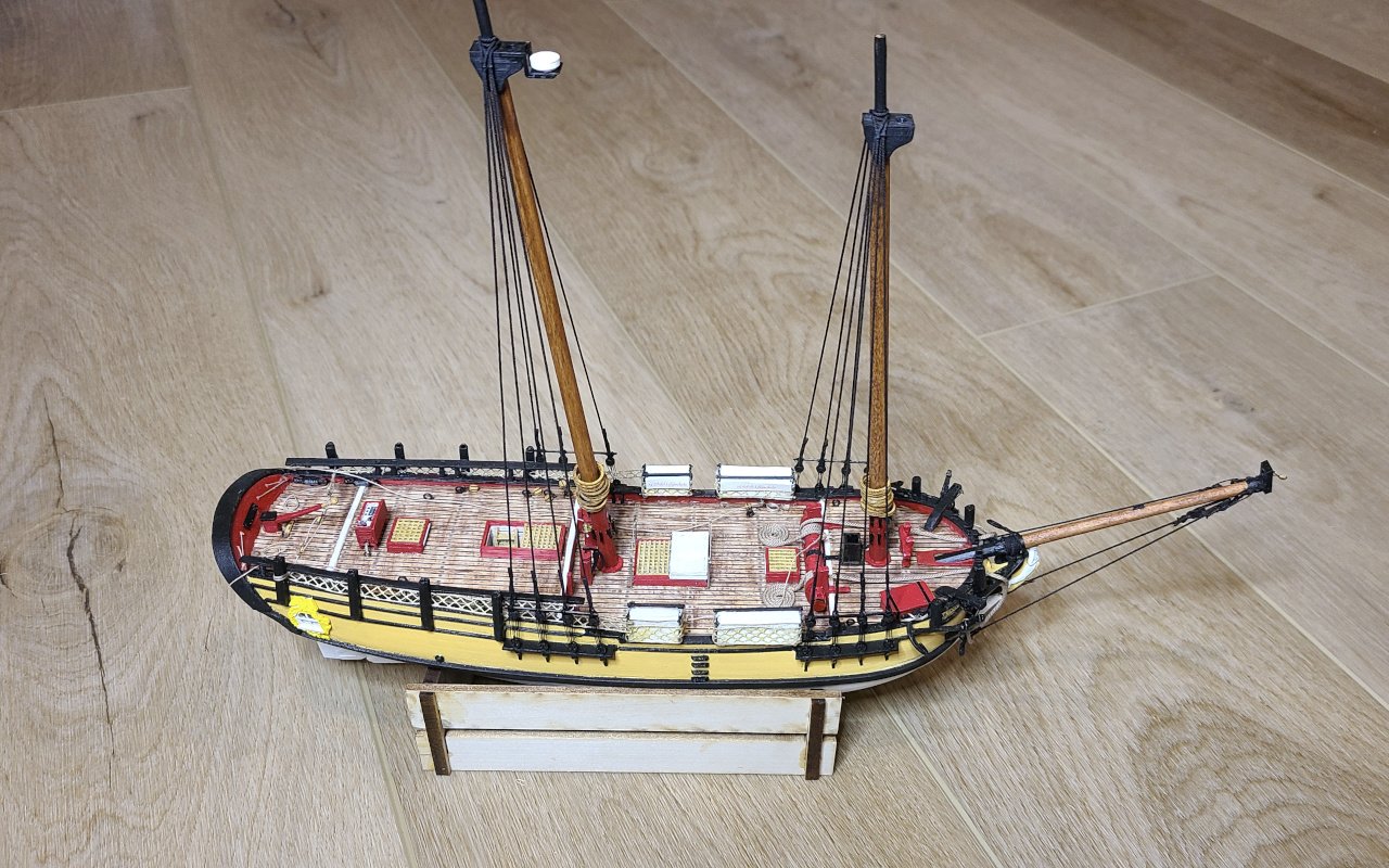
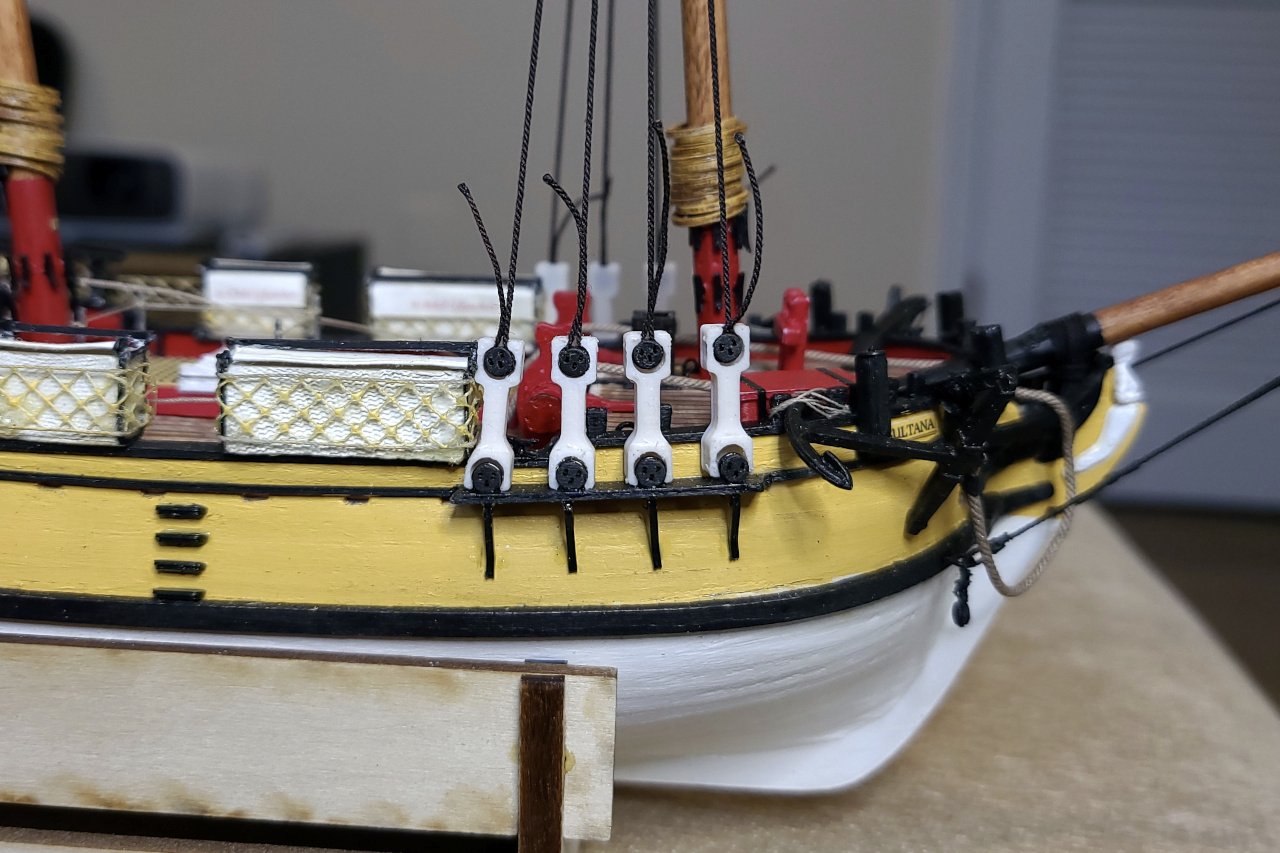
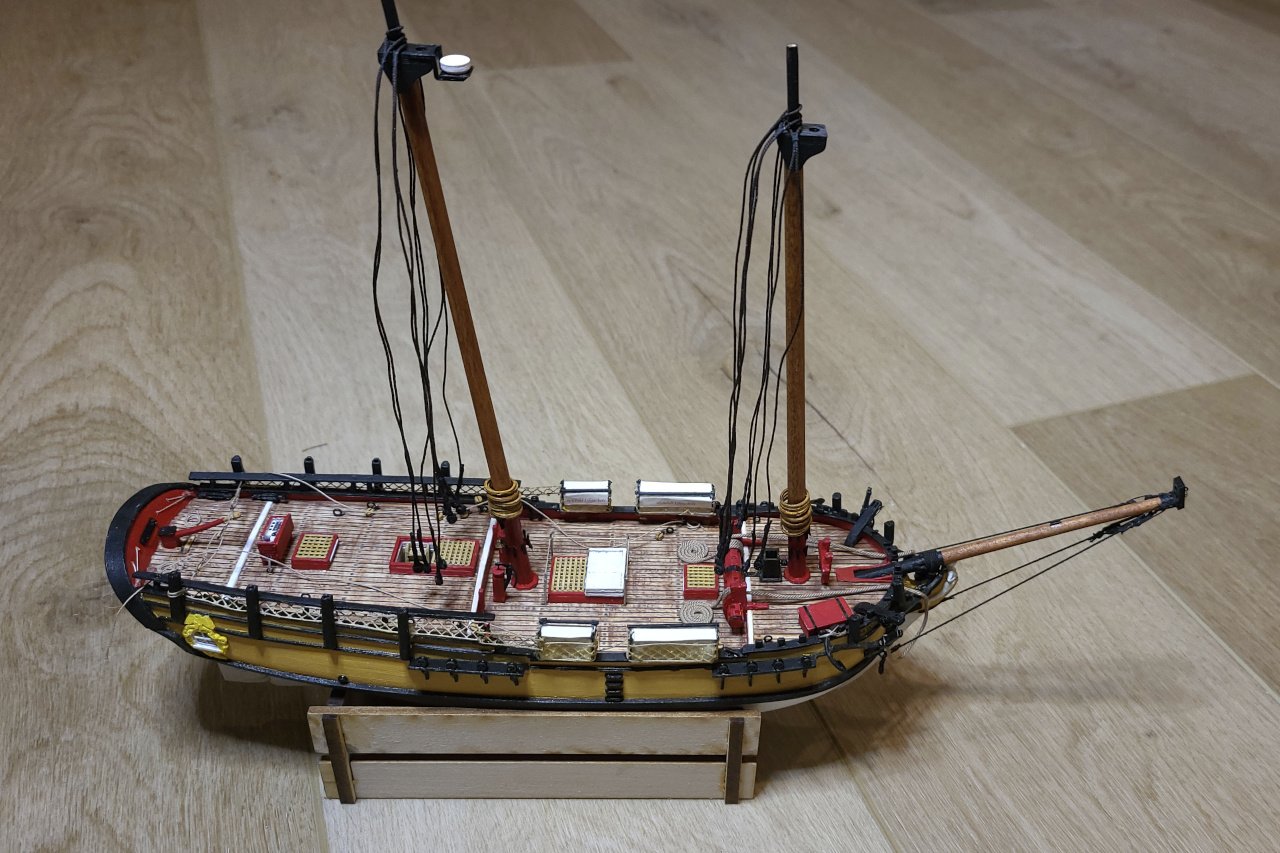
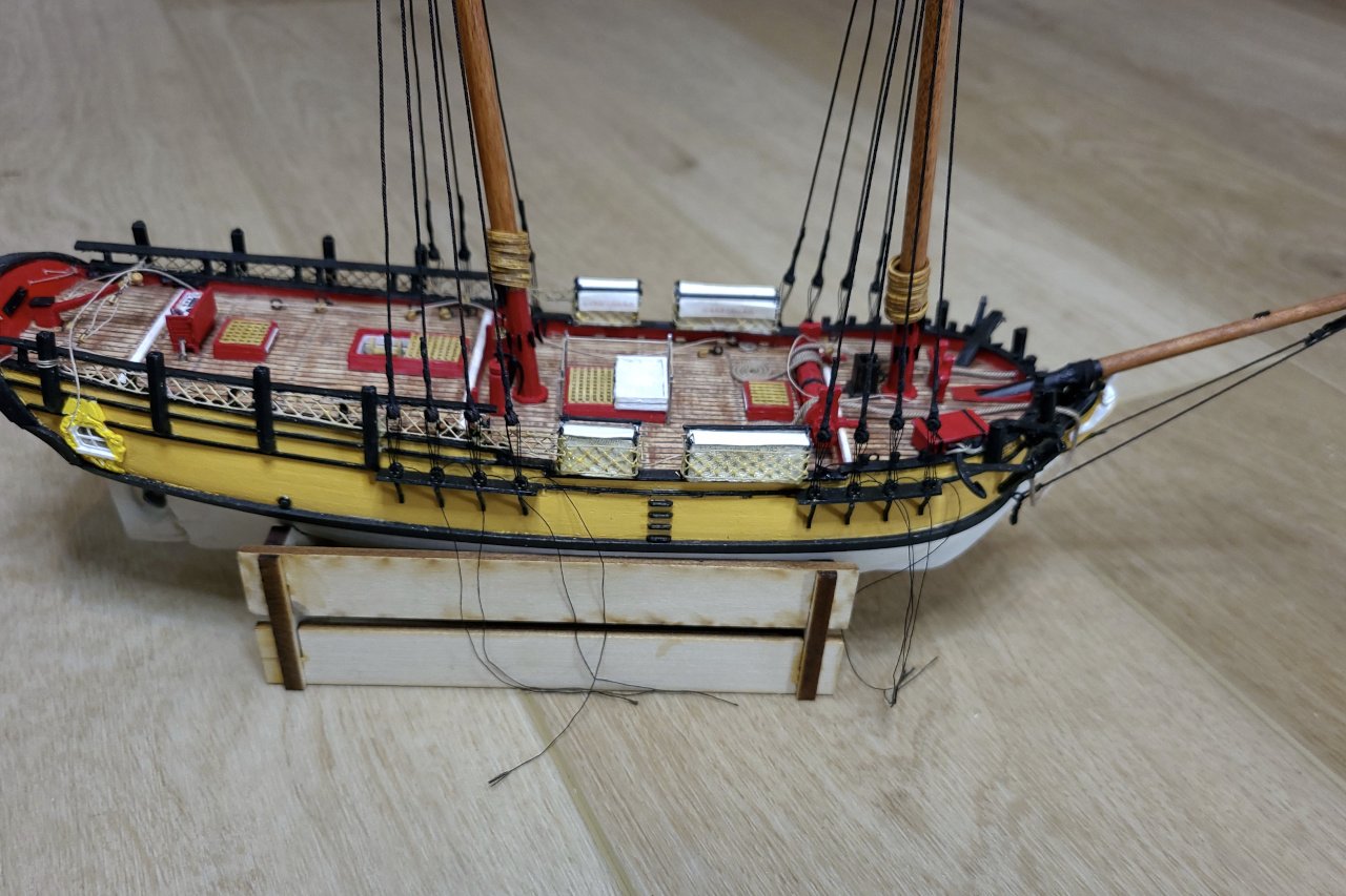
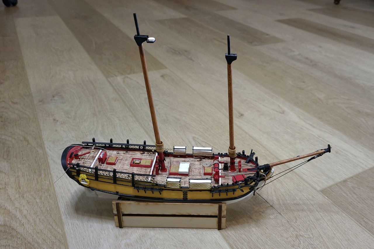
Below is a picture of my Sultana, still in progress. As an experiment, I have been using 3D printing for as many parts as I can. Results have varied. Some parts are convincing, others suffer from the limitations of 3D printing with a consumer-level printer. There is a limit to the level of detail, and sharp edges are often impossible to achieve. And, of course, even when painted well, plastic can't match the texture and appearance of wood. Anyway, look it over, try to spot what is 3D printed, and I'll list the 3D printed pieces below the image. List of 3D printed parts: White figurehead Yellow quarterbadges All the black railings, caprails, stanchions, hull trim, channels, catheads, etc. Most items in red including the tiller, binnacle, hatches, pumps, windlass and bitts Gratings on the hatches Mast hoops Mast cleats Mast caps and bowsprit cap Have a look at my build log for details of each specific part.
-
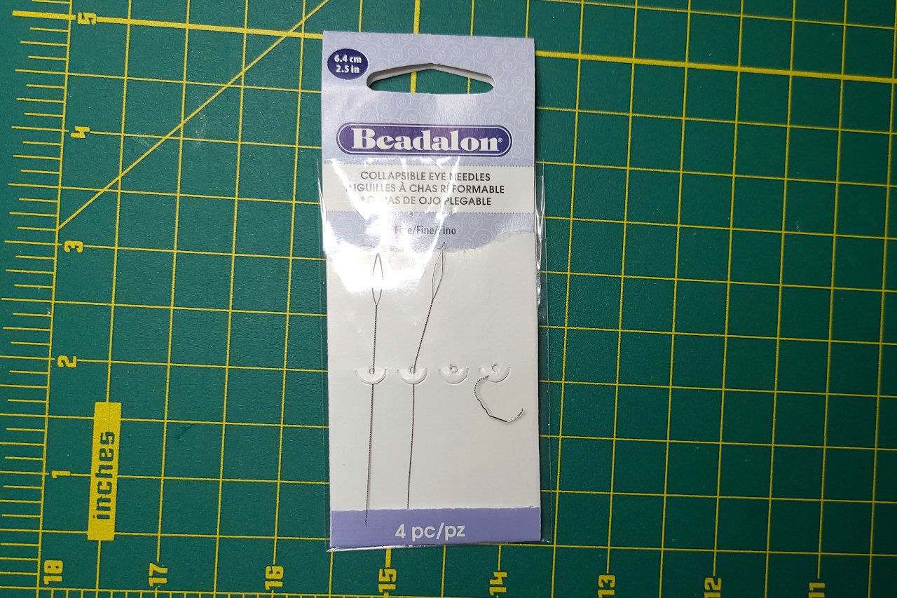
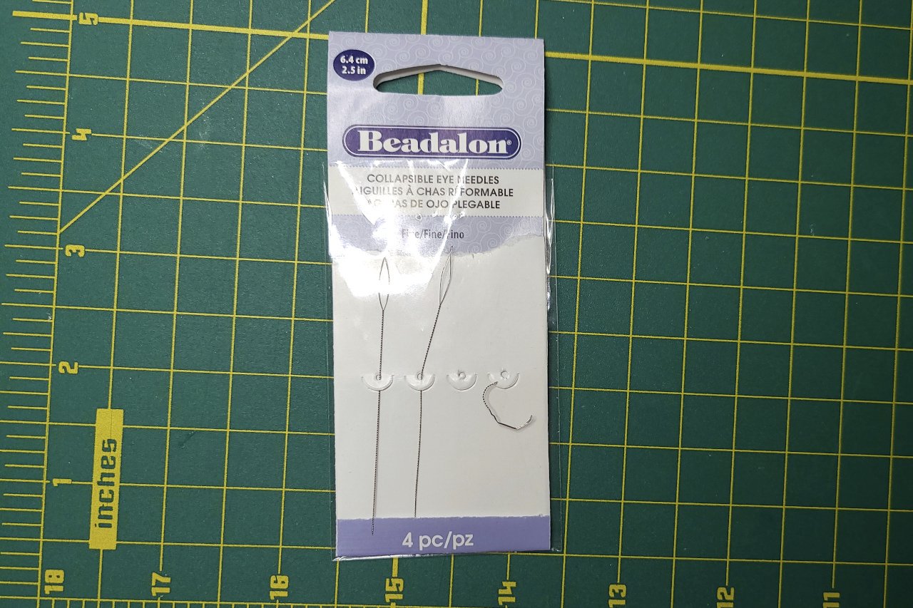
For the deadeyes on my Sultana, I used the very thin beading needles pictured below. These are by far the thinnest needles I have found. However, even though the needles are flexible, I could not use a full needle because the deadeyes are mounted so close to the hull. I get around this, I cut a needle short and bent it into a curve. The bent needle, much abused but still in one piece after threading 16 pairs of deadeyes, is also visible in the picture.
-
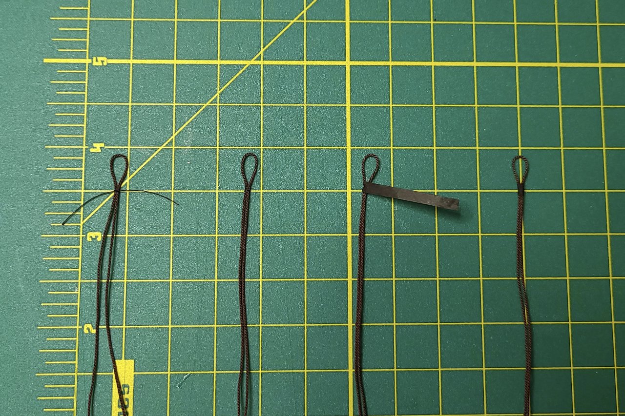
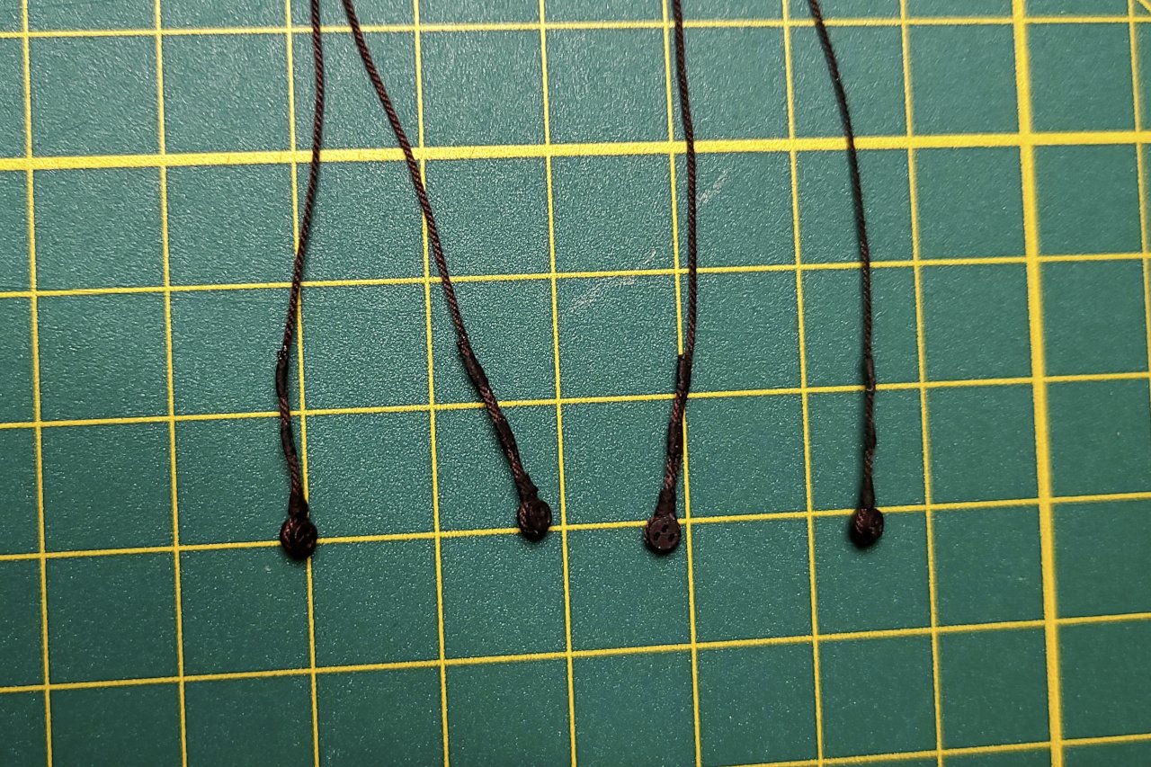
Right. The single thread at the beginning really just serves the purpose of holding the ropes together so a little CA glue can actually bond them. The crepe paper covers the glued spot, and both adds strength to the bond and adhesion, since it's saturated in the diluted glue. I have tugged at the seizing points and they are held together well enough to endure some abuse. At 1/64 scale (and probably 1/96, 1/128, etc.) it's an effective illusion of seizing and much easier than seizing with thread.
- 222 replies
-
- 2
-
-
- sultana
- model shipways
- (and 1 more)
-
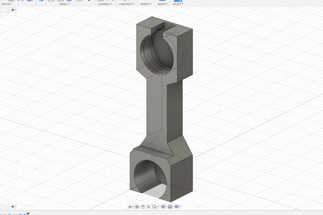
Here is the method I have been using for seizing. I think I found this in the build log of Jersey City Frankie's Niagara, though I am unable to find that build log anymore. The procedure is as follows: Tie thin thread at the point where the ropes join and secure with a tiny drop of CA glue. Cut off the loose ends of the thread. Use a tiny drop of CA glue to attach a small strip of black crepe paper and wait for it to dry completely. Using a mixture of 50% white glue / 50% water, dampen the crepe paper strip and wrap it around the ropes. There is a 3D printed solution to every problem. I was thinking about how to get the correct spacing of the deadeyes, and came up the with part pictured below. Here are the spacers at work. (The upper deadeyes are oriented incorrectly in this picture, but were turned the right way later.) All the deadeyes were seized to the shrouds following the method described above. Now it's time to thread the lanyards. The greatest challenge at this point is the small space between the lower deadeyes and the side of the hull. In order to fit the lanyard line through the lower deadeyes, I cut short a thin beading needle and bent it into a semicircle. The final state of the poor abused needle, after all the lanyards were threaded, can be seen below. All the lanyards have been threaded but not yet tightened, so they are not yet in their final, properly spaced positions. But this is a good stopping point for this build log entry.
- 222 replies
-
- 6
-
-
- sultana
- model shipways
- (and 1 more)
-
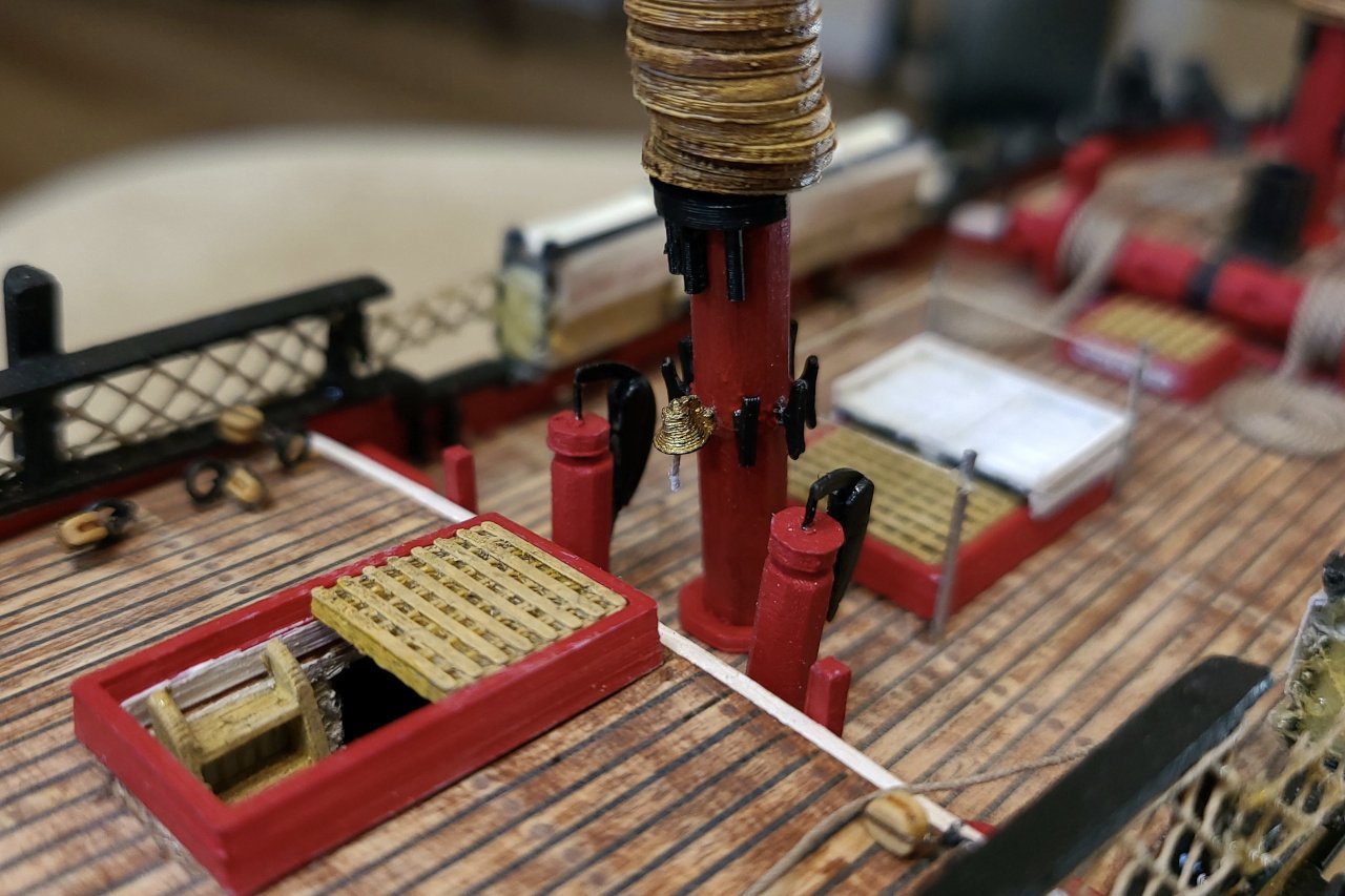
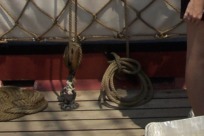
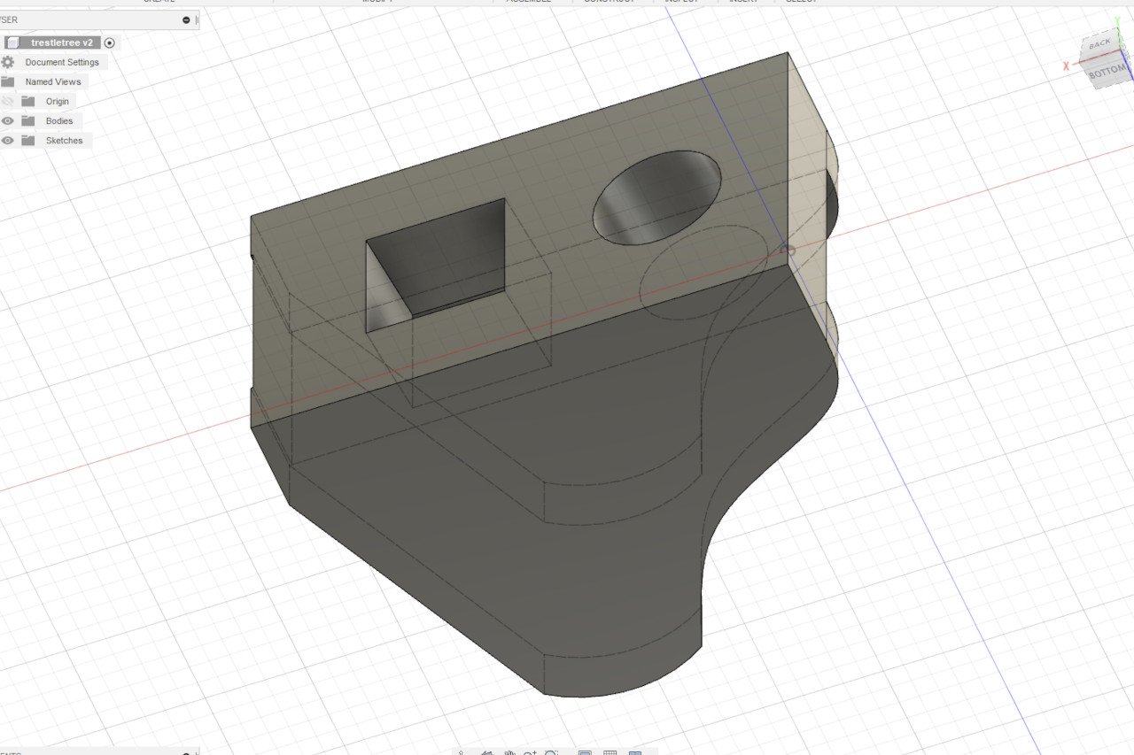
The ship's bell can be found on the back of the mainmast. These cleats on the bulwarks are for the foremast running backstays. There is no way I will be able to reach them once the shrouds are in place, so I attached some line and left a length sufficient (I hope) to rig the backstays later. Here is a picture of that particular cleat on the actual ship. Finally the masts were glued in and the trestle trees on top of them. The mainmast trestle tree has a platform for the radar. Here is the 3D design for the trestle tree. Next time, the shrouds.
- 222 replies
-
- 4
-
-
- sultana
- model shipways
- (and 1 more)
-
The anchors have been added. I'm mostly satisfied, but in hindsight, I feel that a thinner anchor cable would be better. (I used the .045 miniature rope as in the Sultana practicum.)
- 222 replies
-
- 4
-
-
- sultana
- model shipways
- (and 1 more)
-
I attached blocks and line for the tiller. This was my first time using the Syren 2mm blocks. Manipulating them and threading line through them was a big challenge. There are some other areas of the ship that call for these small blocks and I'm not looking forward to it.
- 222 replies
-
- 4
-
-
- sultana
- model shipways
- (and 1 more)