HOLIDAY DONATION DRIVE - SUPPORT MSW - DO YOUR PART TO KEEP THIS GREAT FORUM GOING!
×


SardonicMeow
-
Posts
333 -
Joined
-
Last visited
Content Type
Profiles
Forums
Gallery
Events
Everything posted by SardonicMeow
-
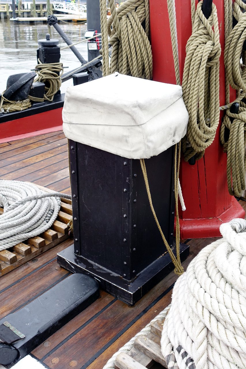
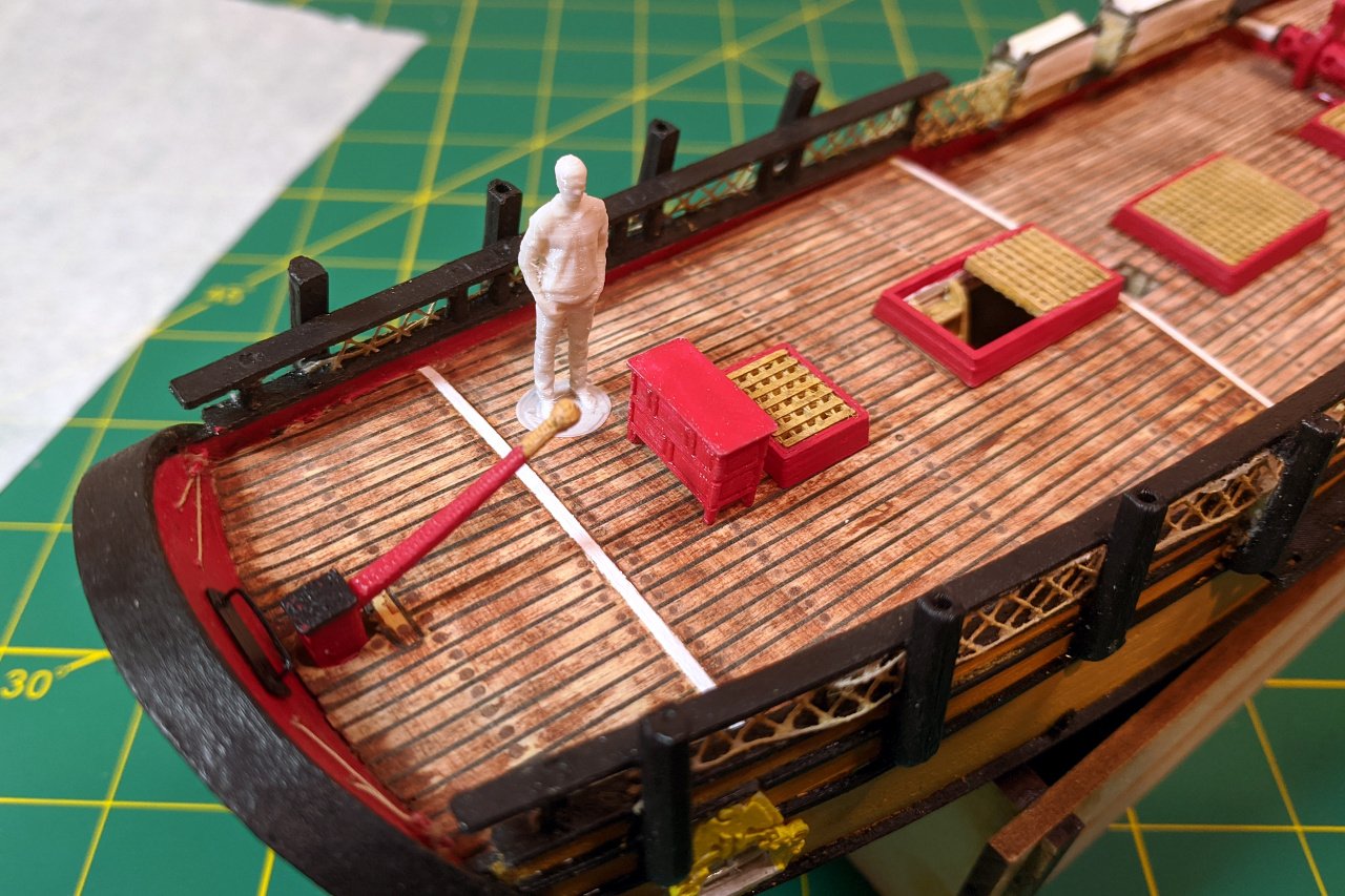
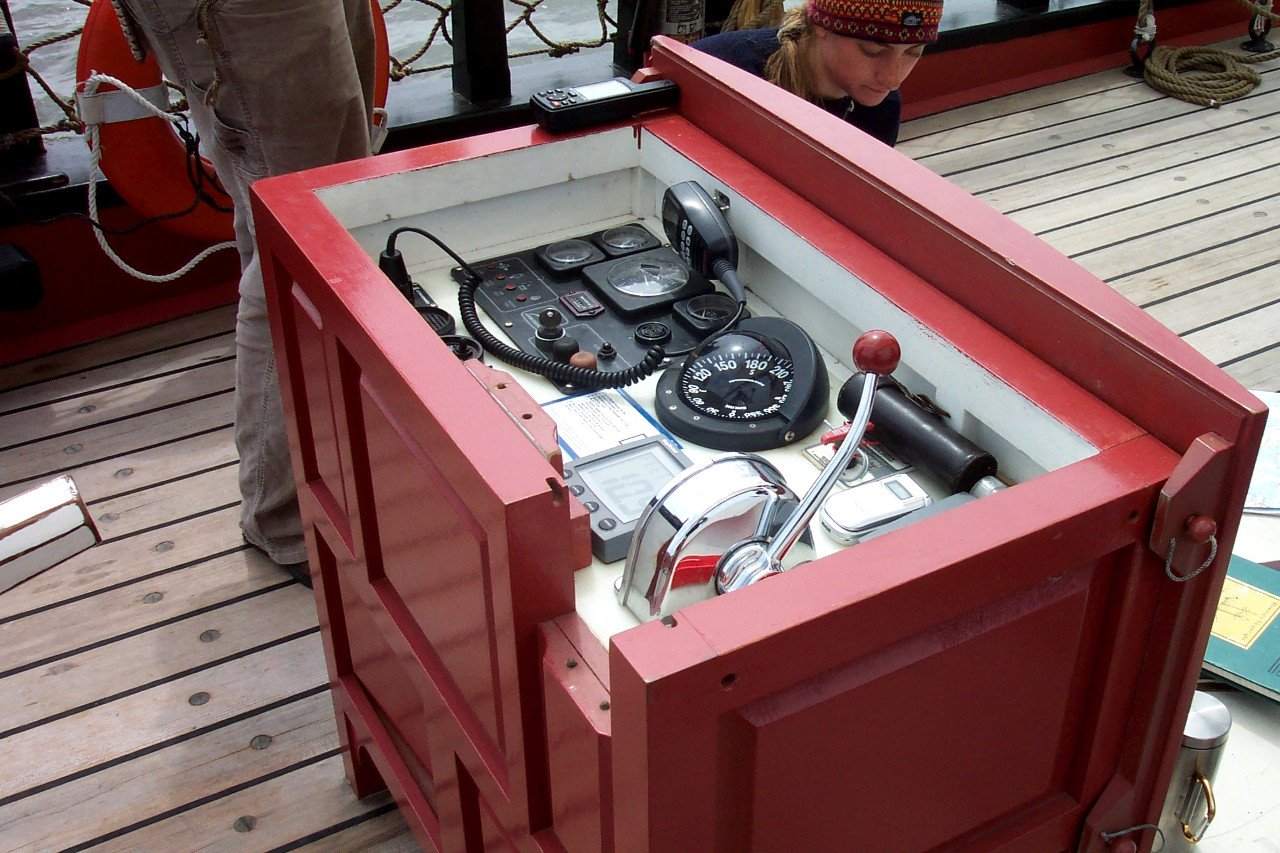
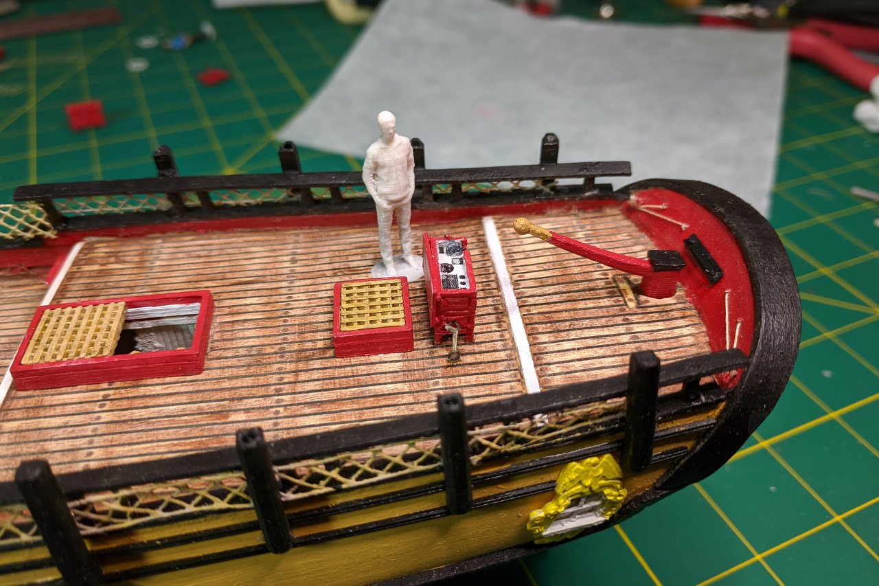
 I started work on the binnacle by creating a 3D design with the lid on. This was not bad, but a bit boring. The best picture of the open binnacle I have found is from ship25bsa.smallsquareddesigns.com, which has been a great resource for reference photos. I first tried adding the details of the instruments as raised parts of my 3D design, but it was beyond the ability of my 3D printer to render them in sufficient detail, so the result was just little plastic blobs, which were made worse after painting. My revised design replaced the instruments with a little piece of paper. Testing the binnacle on the model. And finally it is glued on and tied down to rings on the deck.
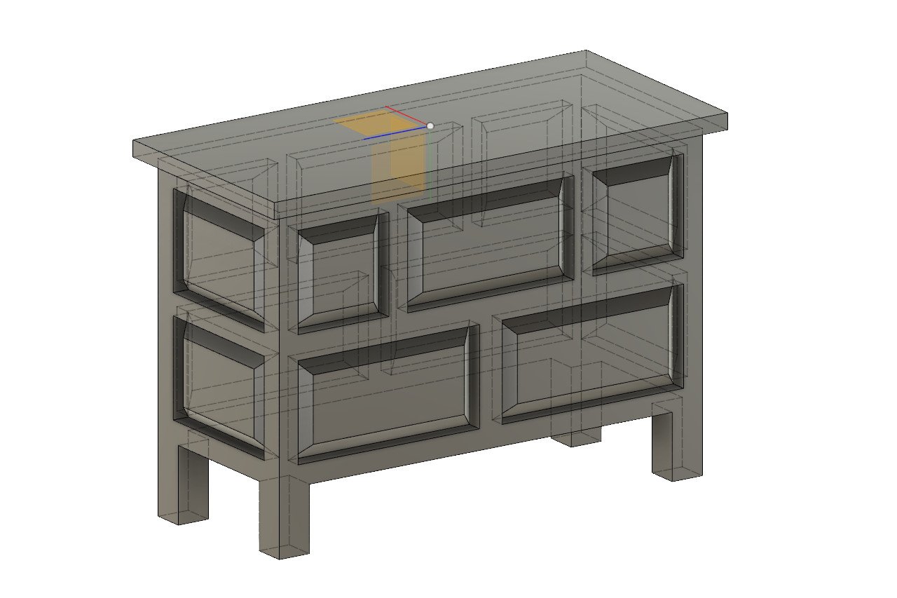
- 222 replies
-
- 5
-

-
- sultana
- model shipways
- (and 1 more)
-
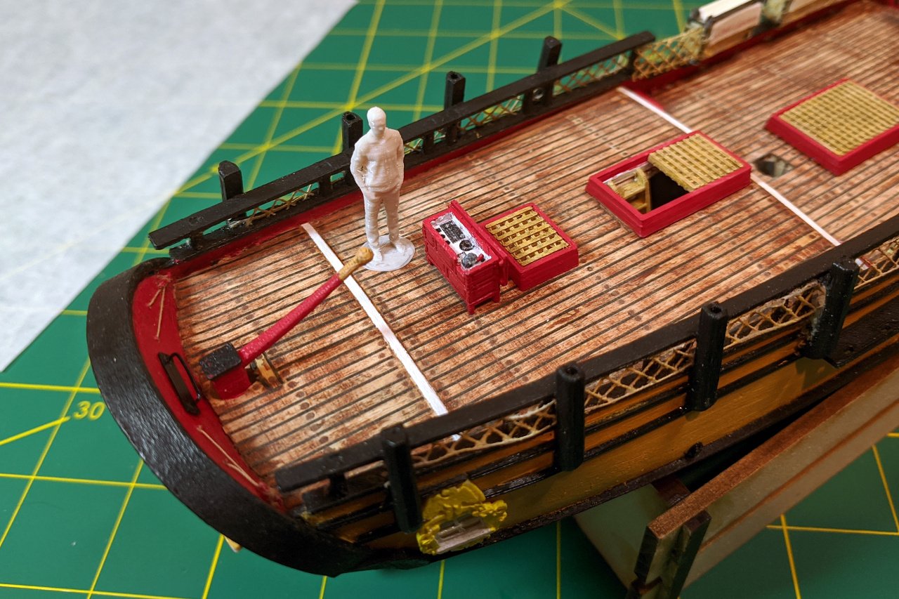
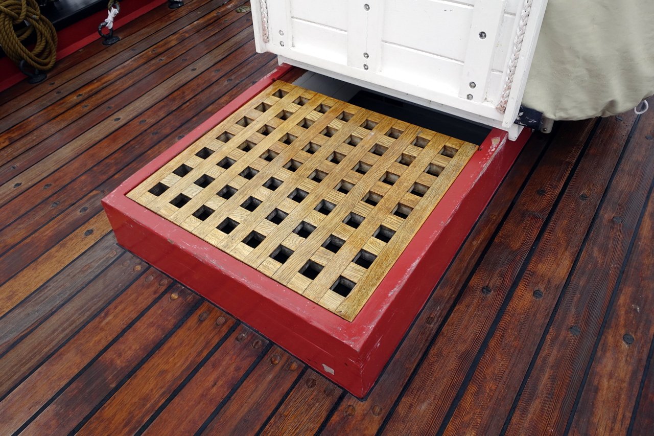
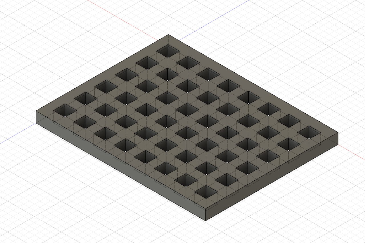
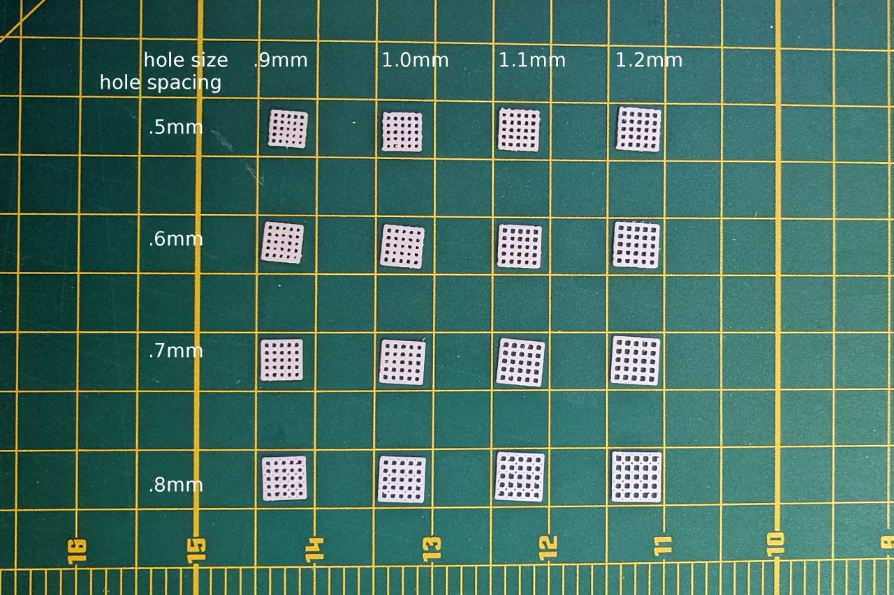
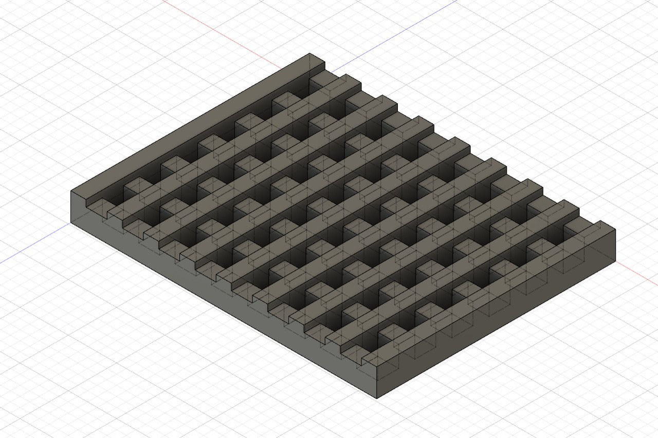
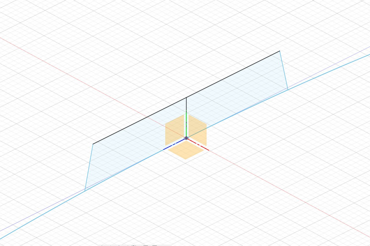
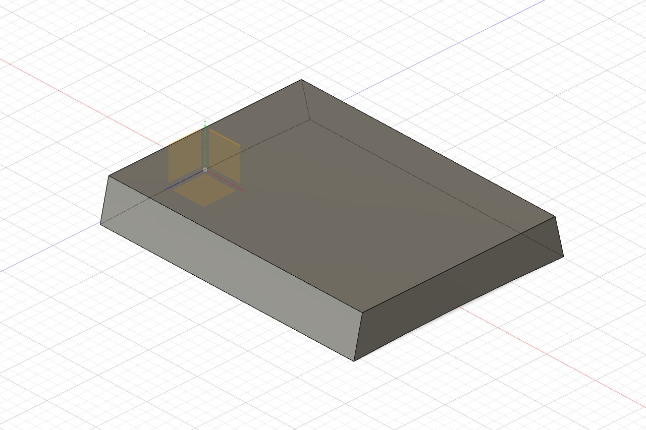
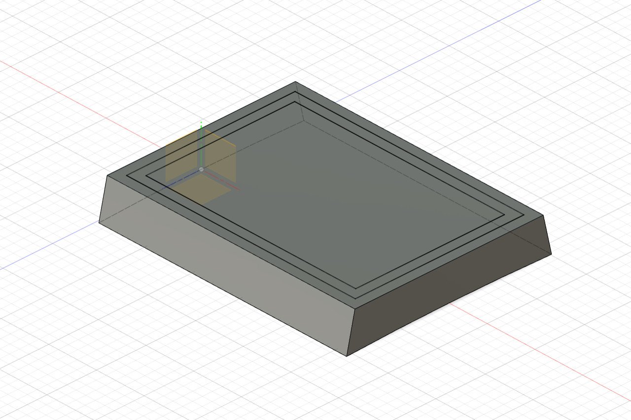
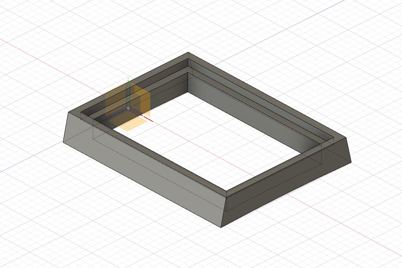
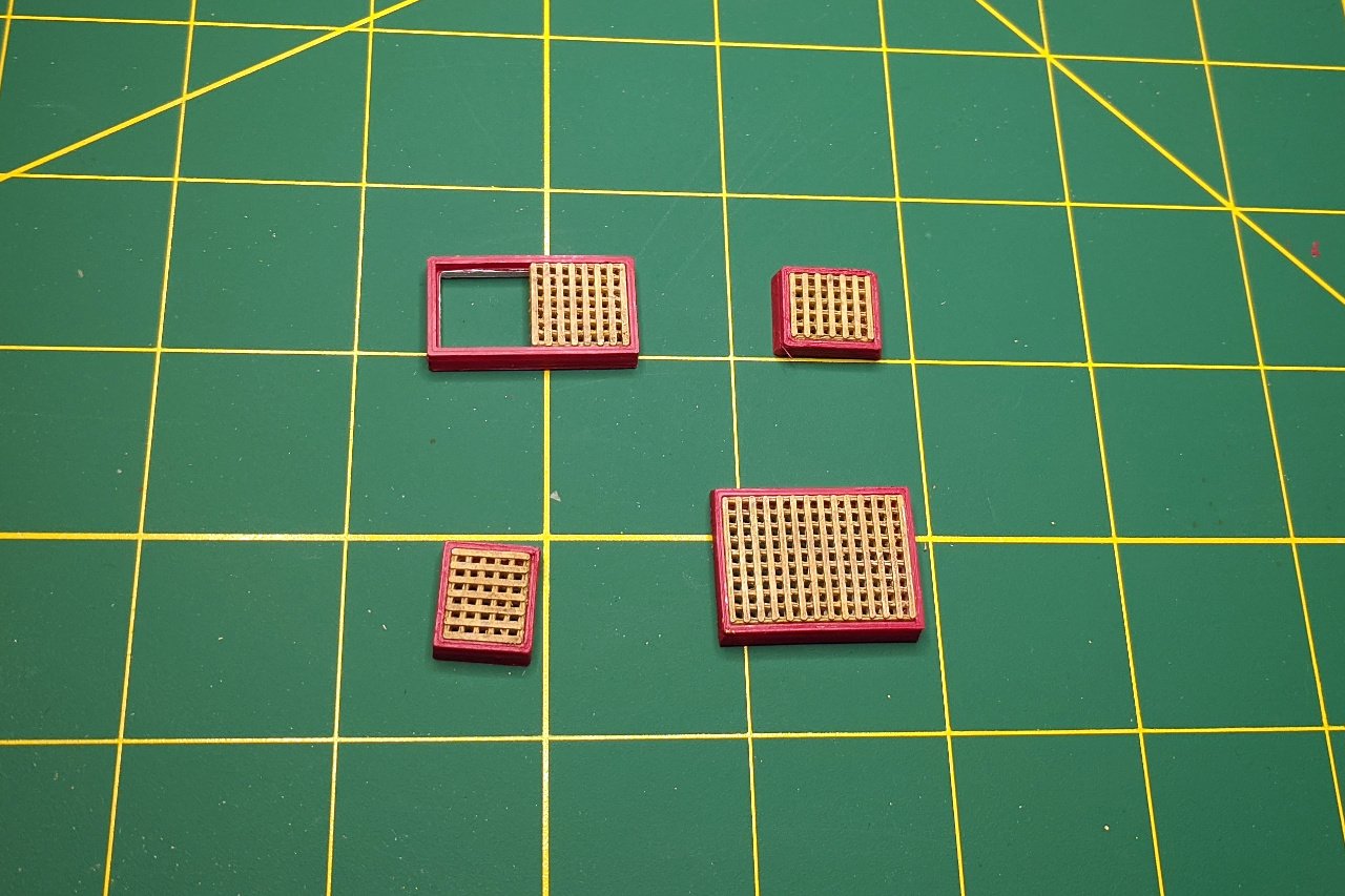
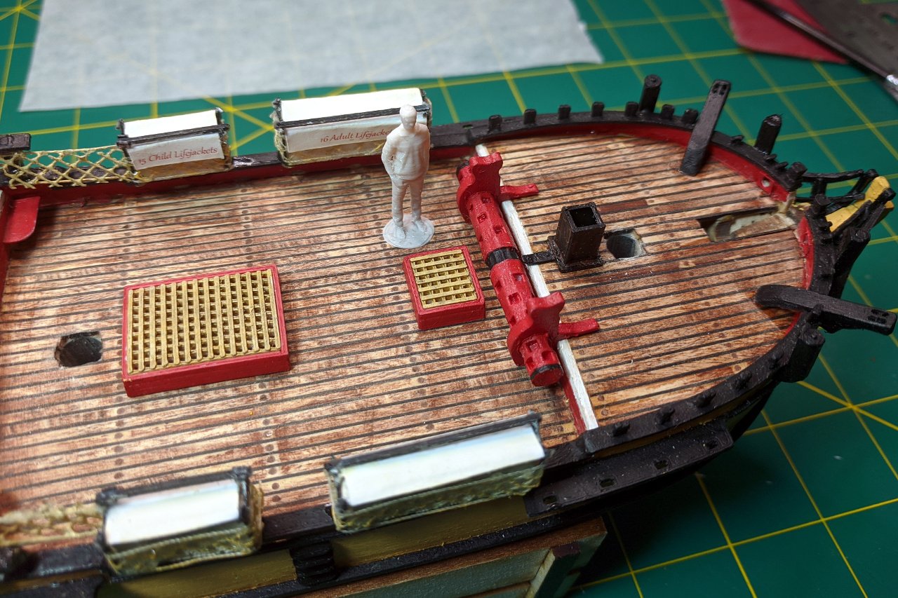
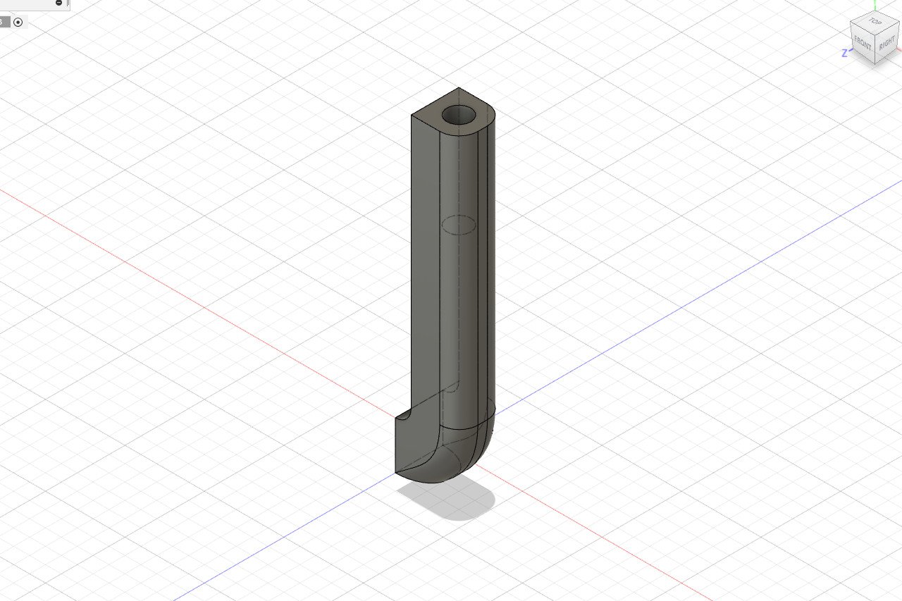
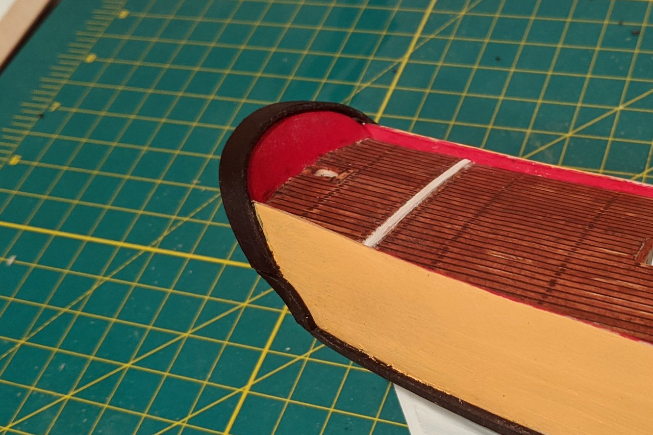
The Sultana has four hatches. Two are small: one is located aft of the windlass and the other is forward of the binnacle. A long, medium sized hatch is on the quarter deck, and will be open to expose the ladder on my model, as it is on other Sultana models. Finally, there is a large hatch on the main deck. Most models depict the main hatch covered with boards, but on the Sultana replica, the large hatch has grating and a ladder down. The picture below is of the medium hatch, with the grating in place to cover the ladder. Note the white cover. All of the hatches on the Sultana have these covers, which keep out water. However, I think I will omit the white covers. Creating a grating in Fusion 360 isn't too hard. Draw a rectangle, draw one of the square holes, use a rectangular pattern to create the remaining holes, then extrude the sketch. For the grating on the Sultana, I need to have the holes and space between holes at roughly .6mm in size. I ran an experiment to see how small I could make grating that still retained square-shaped holes. As you can see, the pieces in the lower right are acceptable, while the ones in the upper right are not. This shows the limits of what I can do with 3D printed grating. After some experimenting, I found that having the surface raised in one direction makes the grating look better. Next is the hatch coaming. From my earlier work, I already knew the exact curvature of the deck camber. From there, I created the profile of the coaming. And then the profile was extruded. I created a new sketch on the coaming surface to indicate where the recess is. And the relevant parts were cut out. After 3D printing and painting, here are my final hatches. And here are the hatches on the model. The aft-most small hatch hasn't been glued down yet, because I need to place the binnacle first, then glue the hatch an appropriate distance from the binnacle.

- 222 replies
-
- 3
-
-
- sultana
- model shipways
- (and 1 more)
-
I know. It's been an interesting experiment, to see how far I can go with 3D printing. I'm not aware of anyone else who has tried making a wood / plastic hybrid like this.
- 222 replies
-
- 2
-
-
- sultana
- model shipways
- (and 1 more)
-
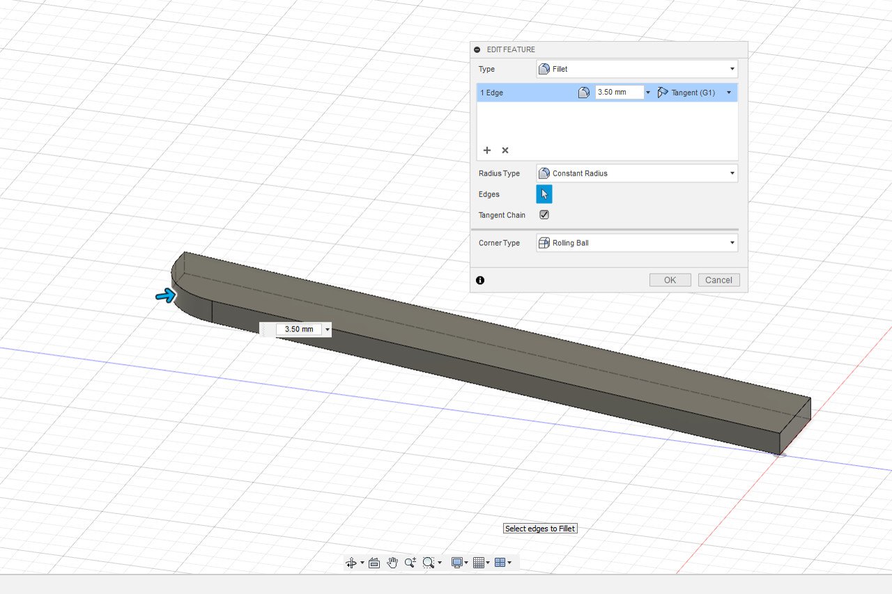
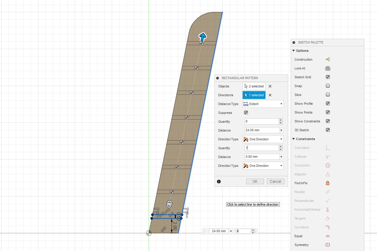
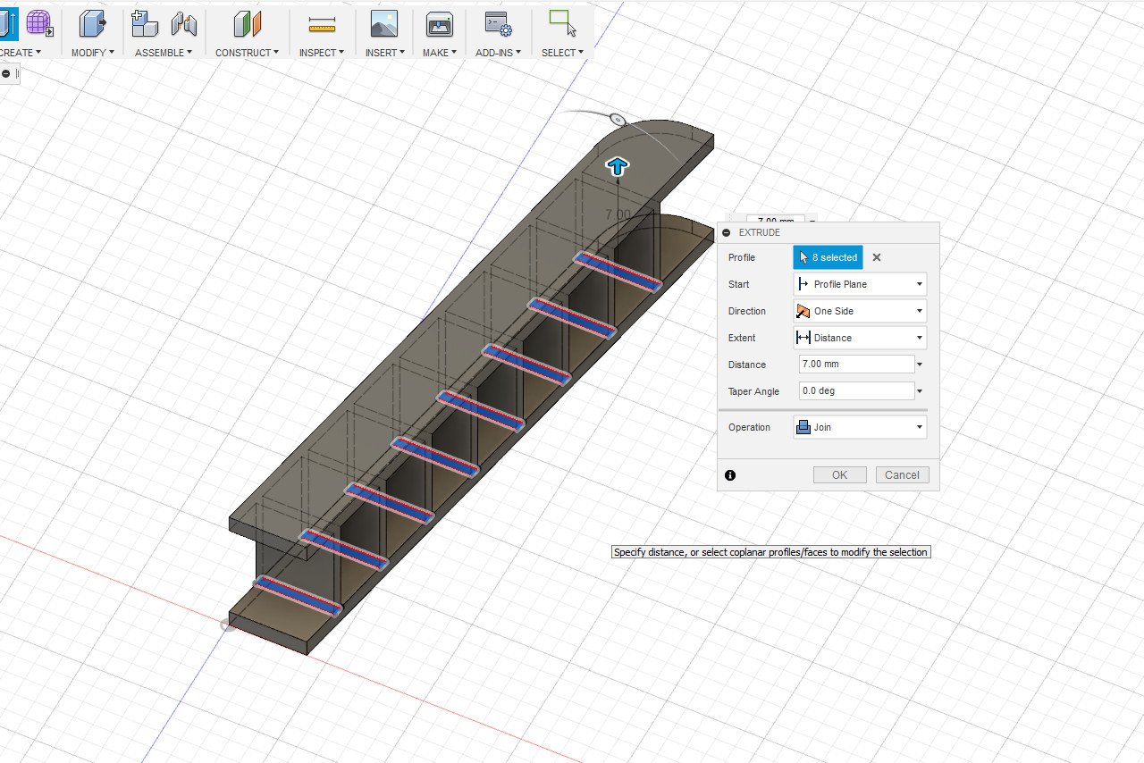
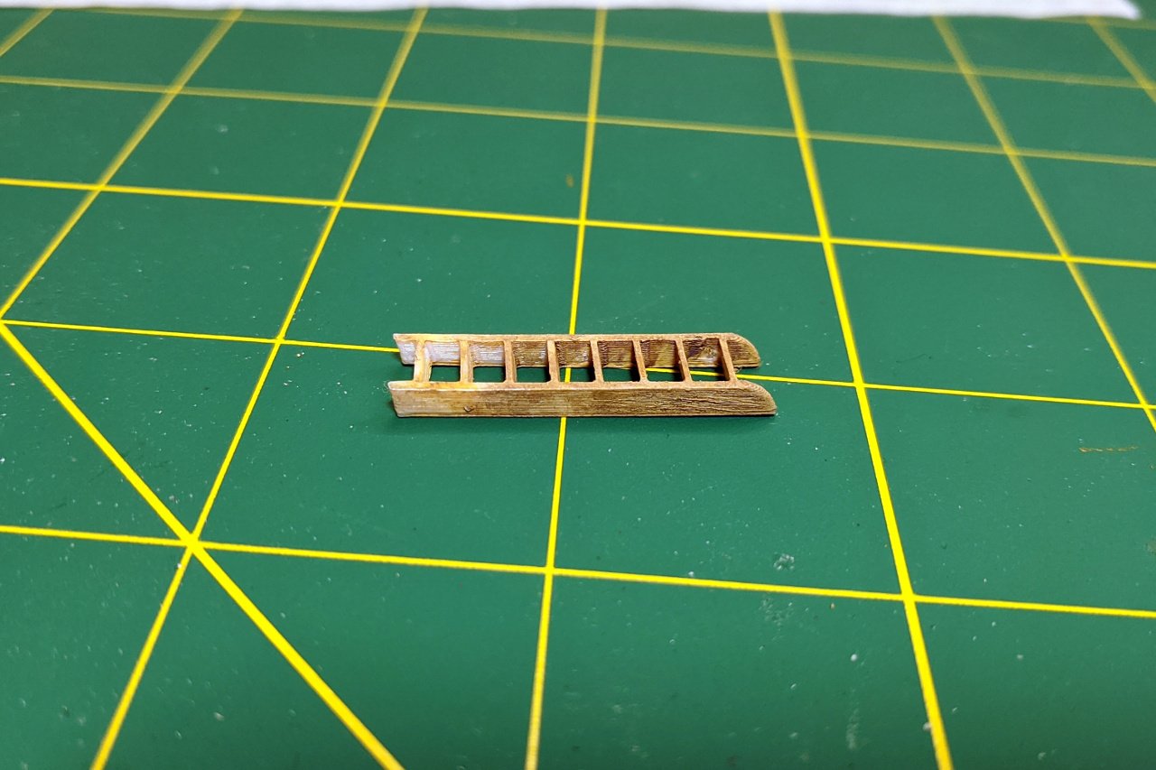
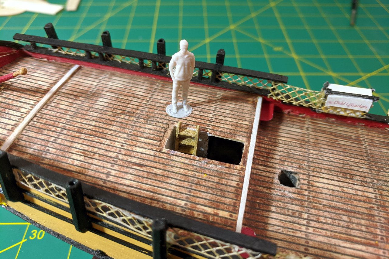
This details building the ladder. First, one side of the ladder is created. The fillet feature allows the ladder to be rounded off at the top. One step of the ladder is created, and a rectangular pattern operation creates the remaining steps. Extrude the steps and add a copy of the side piece, and the ladder is complete. Using a knife, I scribed some lines into the 3D printed part to simulate wood grain. The piece was painted a wood color followed by a brown wash to enhance the texture. And finally, the ladder is glued into place.
- 222 replies
-
- 4
-
-
- sultana
- model shipways
- (and 1 more)
-
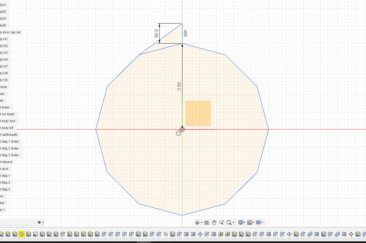
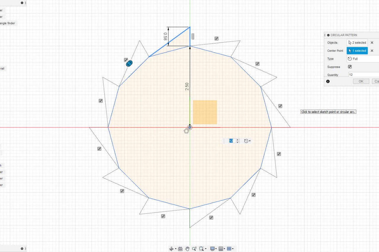
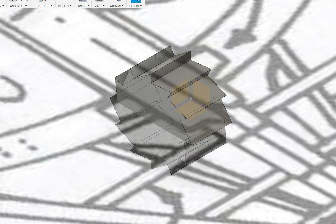
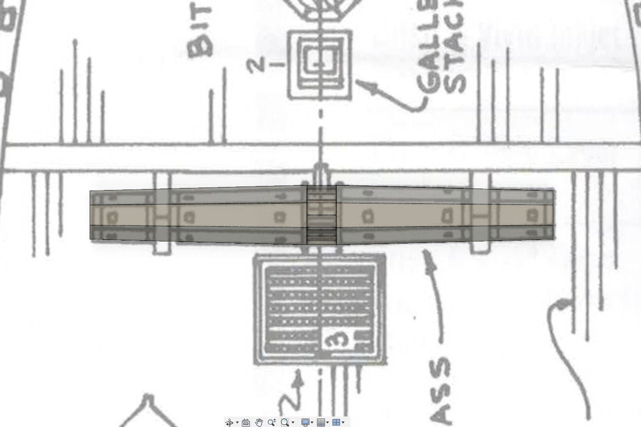
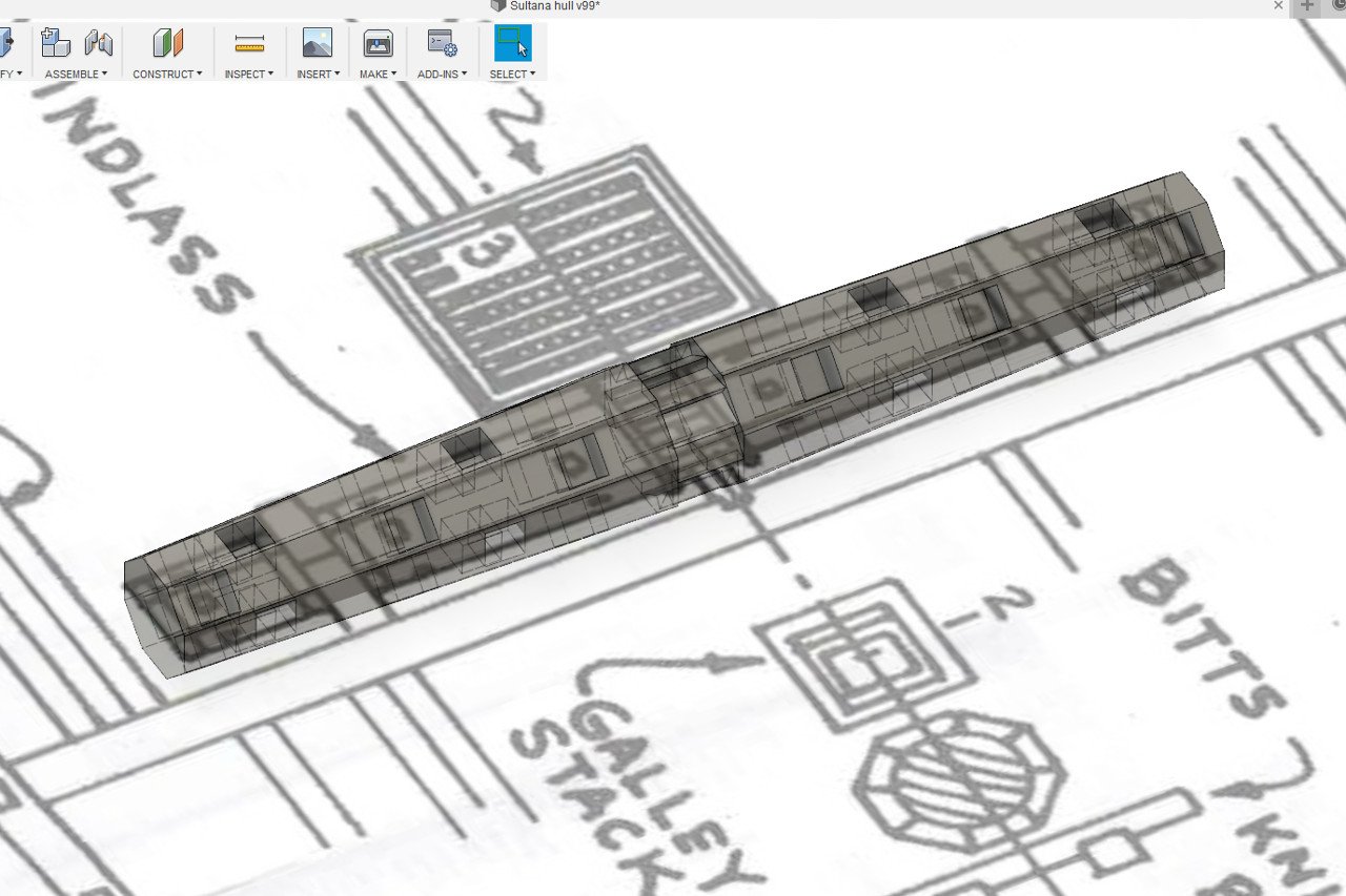
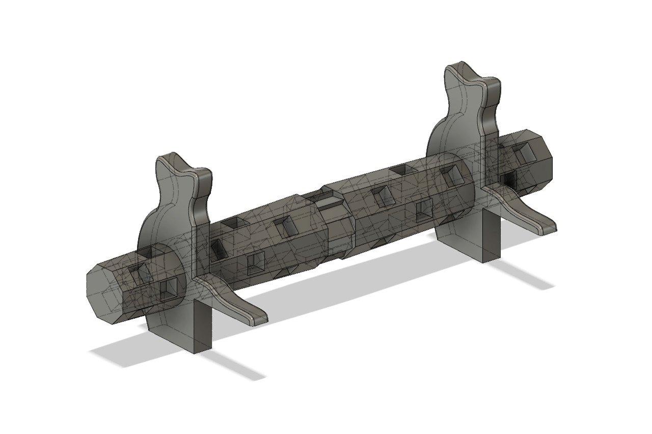
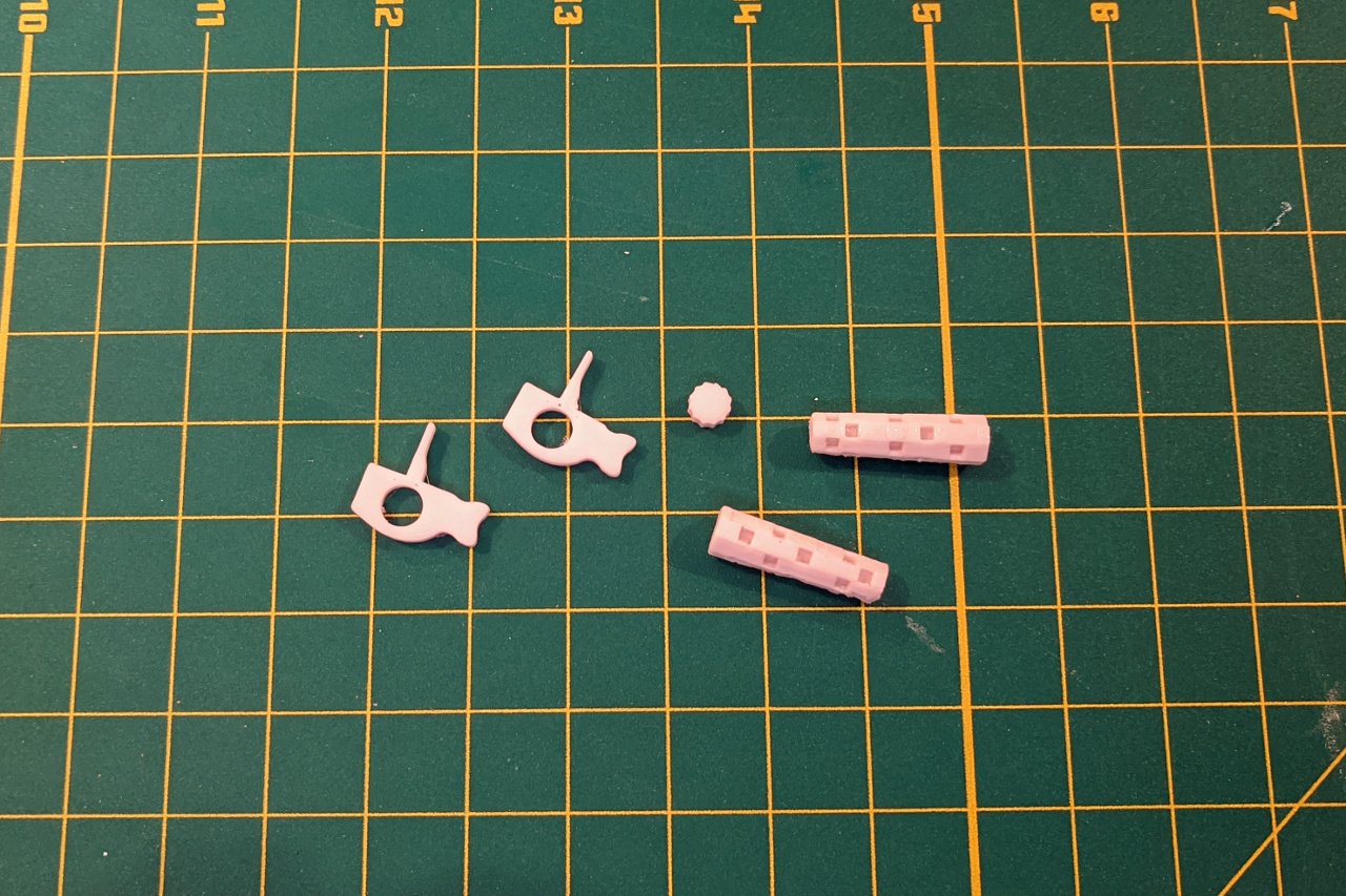
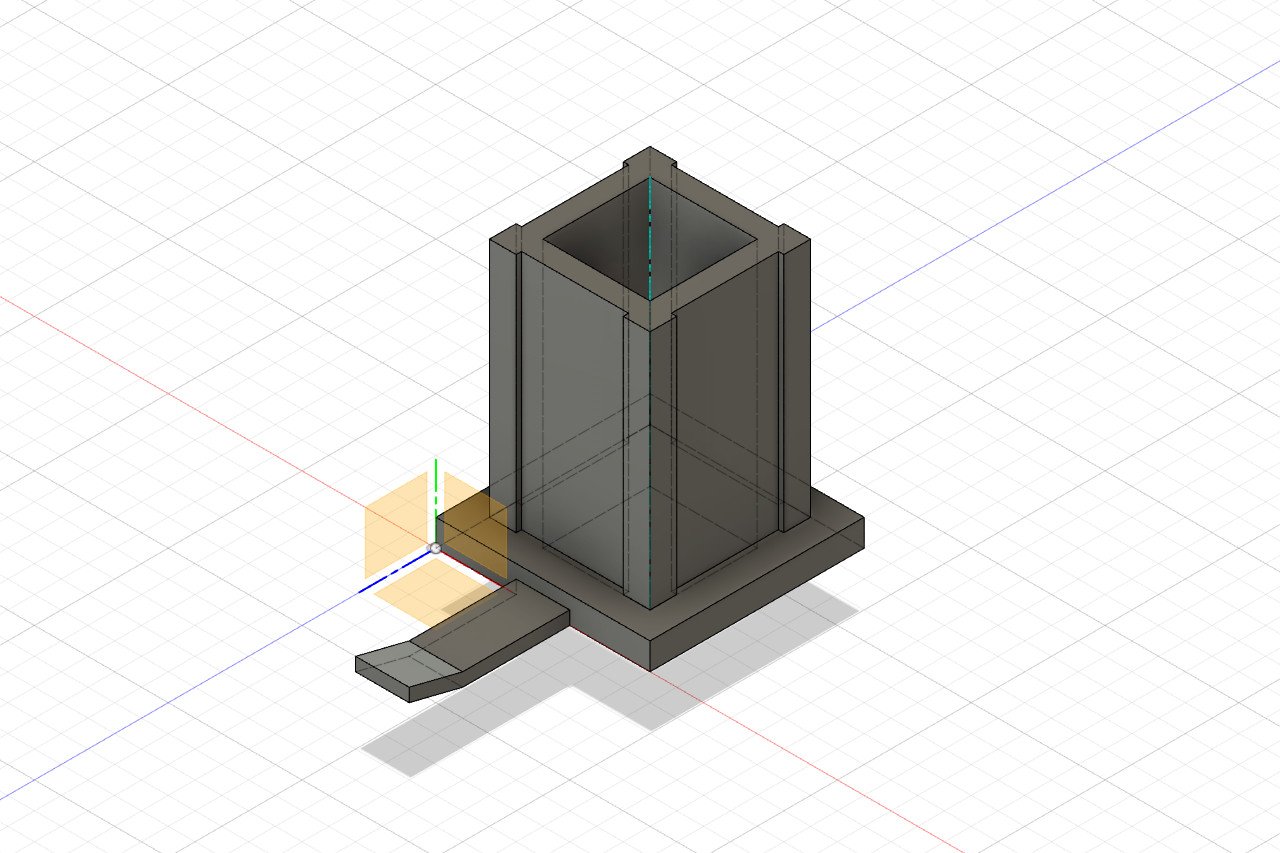
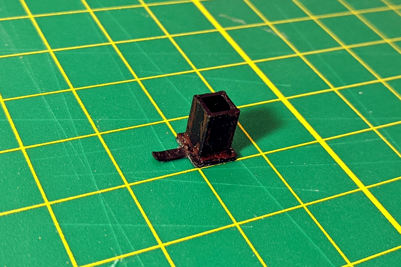
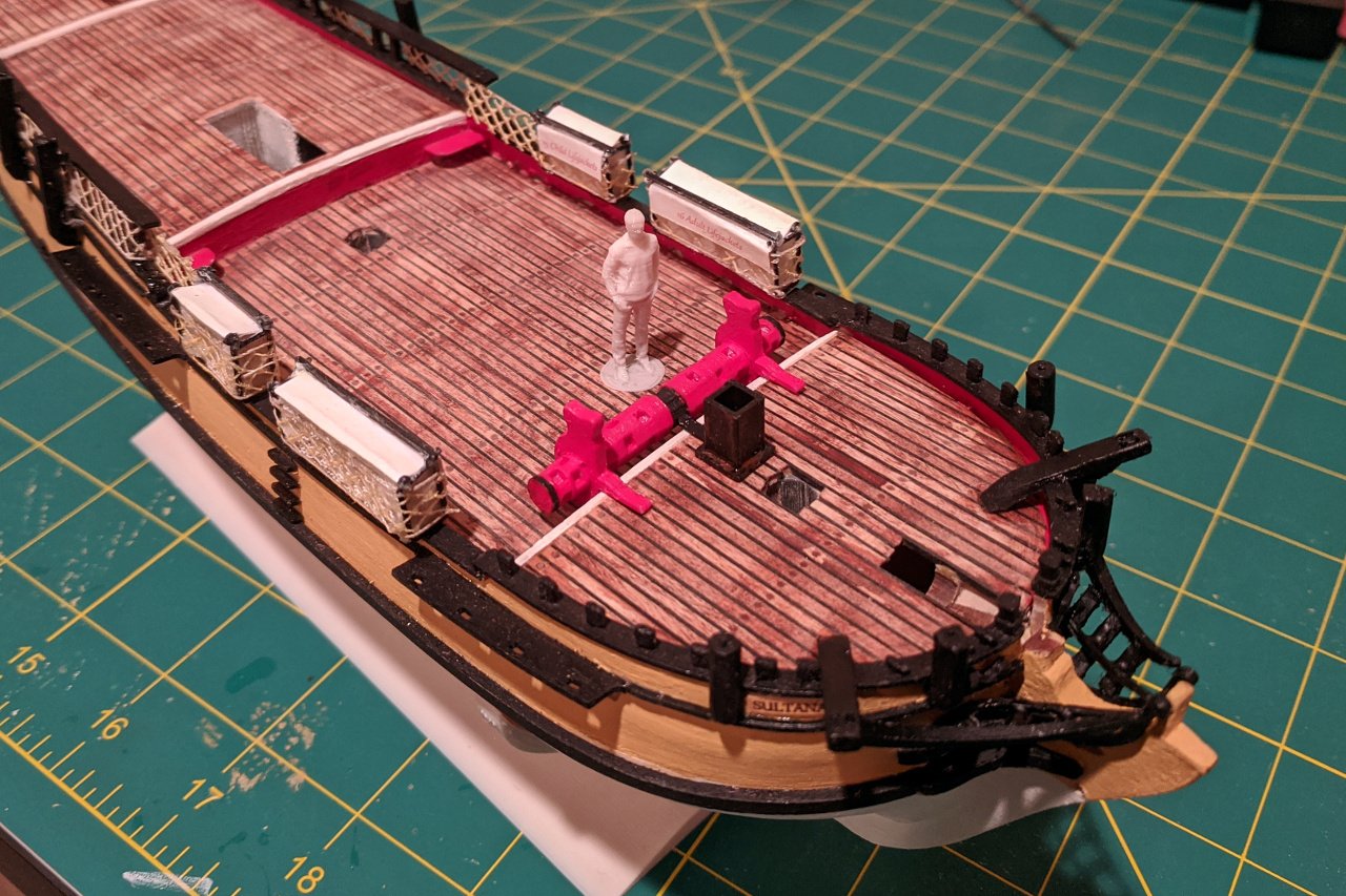
Let's build the windlass, starting with the ratchet gear. After studying a number of pictures of the Sultana's windlass, I determined that the ratchet gear has 12 teeth. I created a 12 sided polygon and added one tooth. Then I used the circular pattern function to copy the tooth for a total of 12 units. An extrude operation created the final shape of the ratchet gear. Adjacent to the ratchet gear, I created an octagon, then a second smaller octagon the correct distance away. I used the loft function to create a shape between the two octagons, then mirrored that shape to the other side. The holes were added and both rectangular and circular patterns were used to place the holes around the windlass. And finally, the supports were modeled. All of the windlass parts were 3D printed. The windlass pawl and galley stack are connected. Here is a picture of the galley stack. For now, I have decided to omit the white cover on the galley stack. This is the galley stack 3D model. And this is the 3D printed part. I used some burnt sienna paint to indicate rusting. (There is no rust in my photo of the galley stack, but it is present on other photos I have found.) The windlass and galley stack glued on to my Sultana.

- 222 replies
-
- 4
-
-
- sultana
- model shipways
- (and 1 more)
-
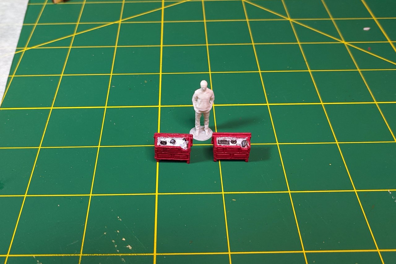
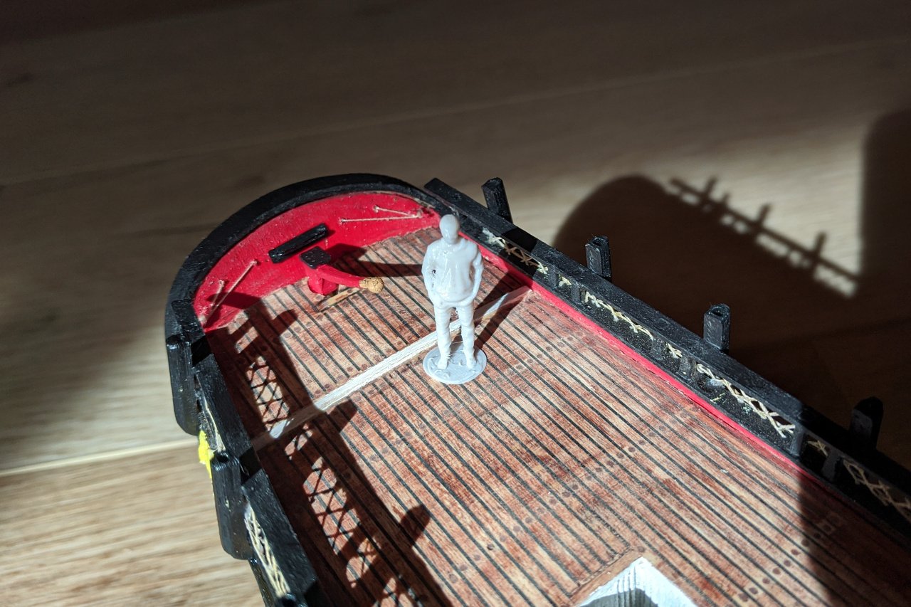
I have been looking at publicly available 3D models in order to find a suitable figure that I might use as a starting point for modeling the Sultana's figurehead. This guy, "Standing figure of Alex" by user thowe on Thingiverse, won't help for the figurehead, but I thought it might be nice to have him available as I work on features of the deck to validate the scale of the pieces I work on. I scaled him down to 1:64, and printed him out. Expect him to appear in future installments.
- 222 replies
-
- 2
-
-
- sultana
- model shipways
- (and 1 more)
-
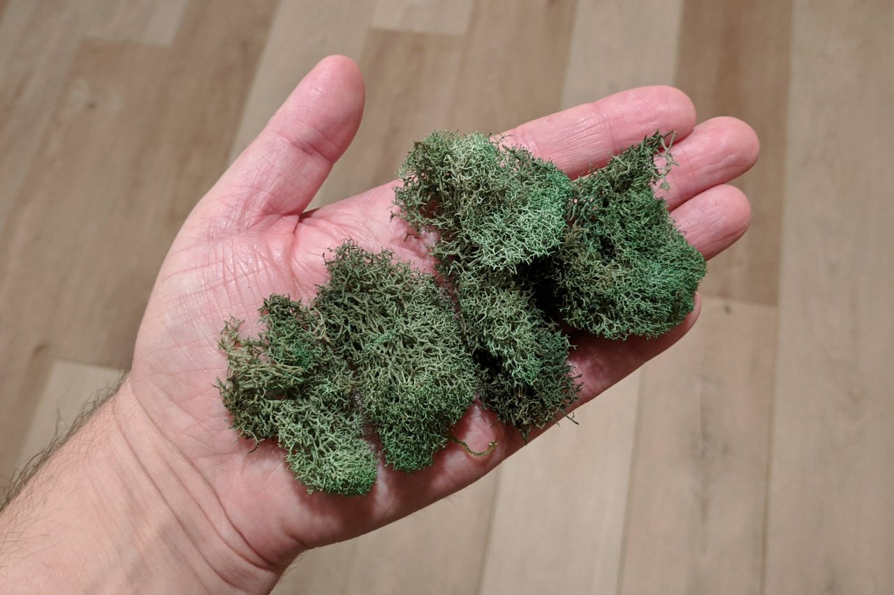
Jon, have a look in your local craft store for dried moss. It may be in the floral arrangement section and/or with materials for model train terrain. I have used it in the past for a diorama, and it may work as seaweed.
-
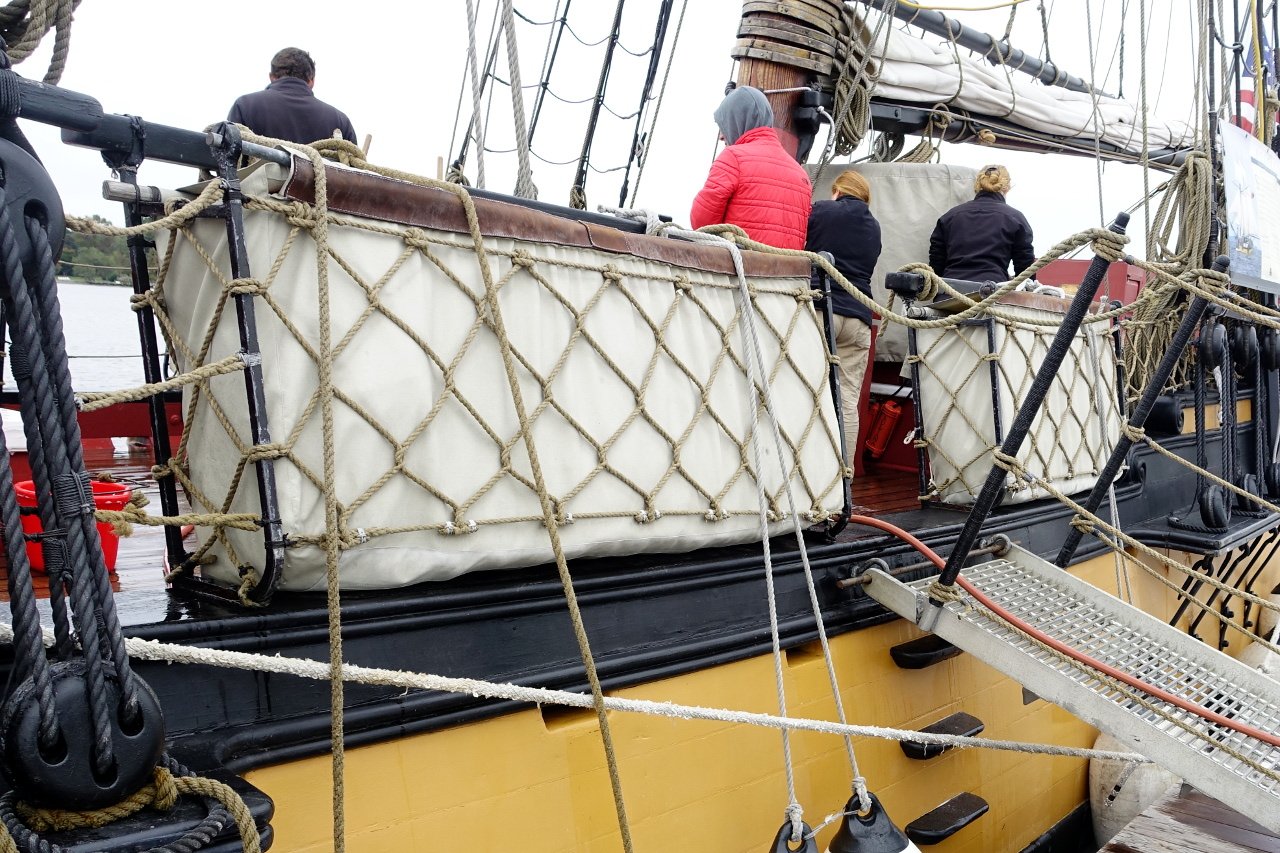
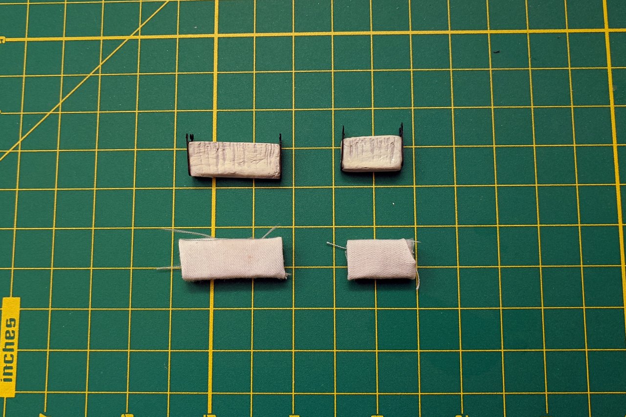
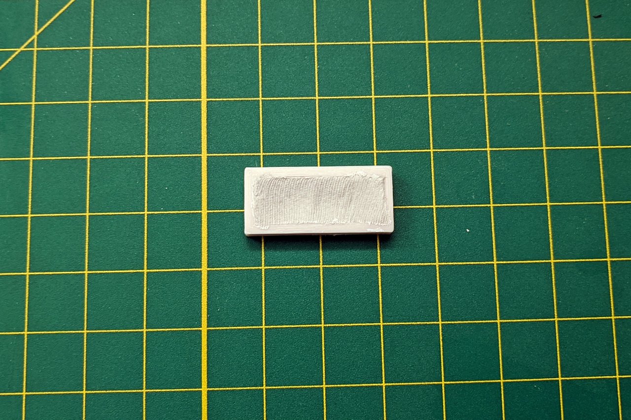
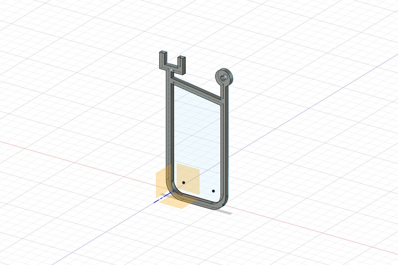
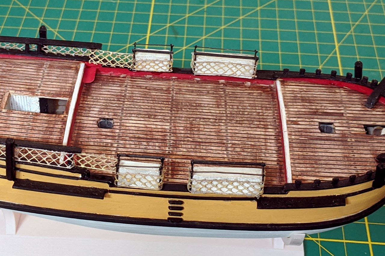
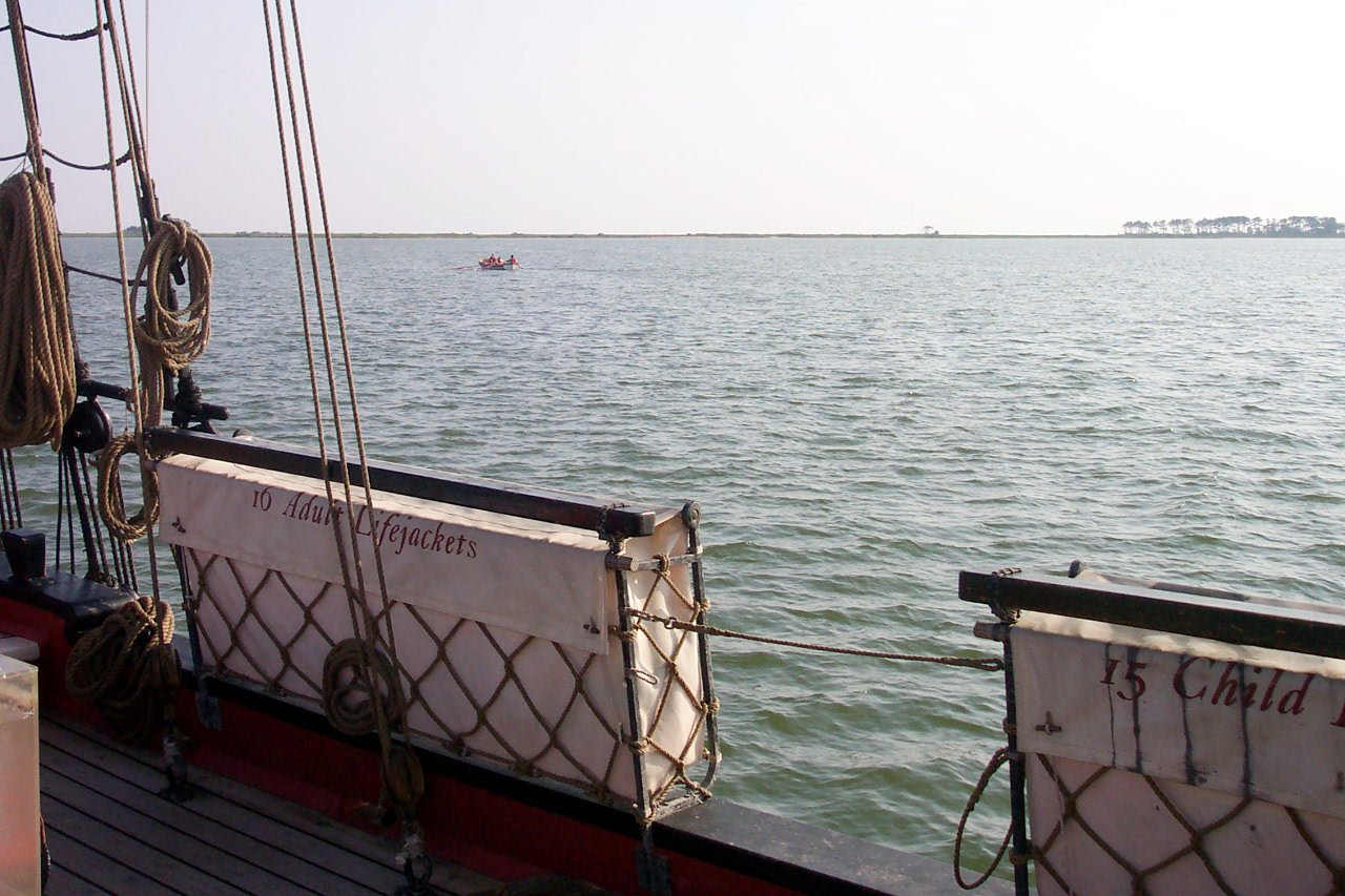
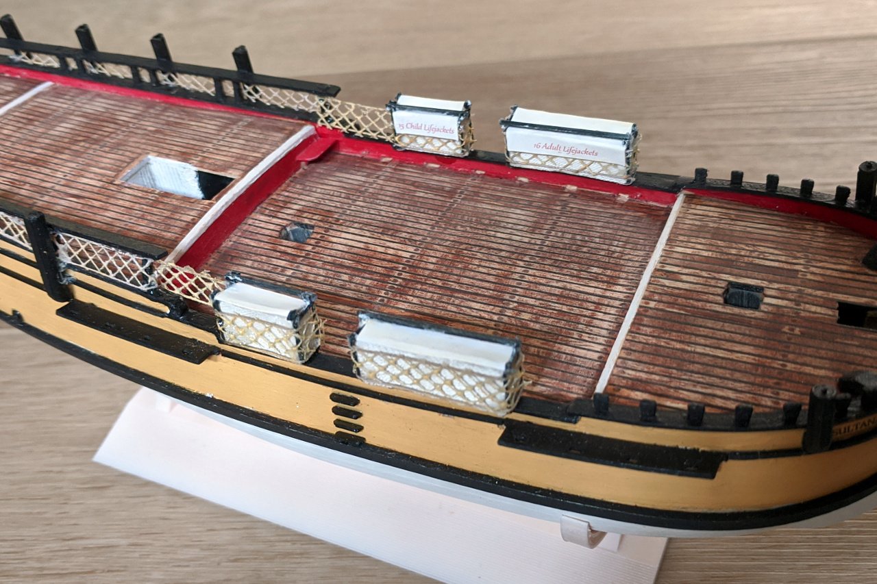
On the Sultana, lifejackets are stored in containers at the sides of the main deck. These are arranged to resemble hammock storage, with rails and netting around them. The picture below is my own of the lifejacket storage. I tried several methods of creating the shape of the lifejacket storage. The top shows an attempt using modeling clay. The lower attempt was using blocks wrapped by fabric. I was not happy with either result. The method I settled on was to create a mold of the correct size, fill it with modeling clay, then press fabric against the side, giving it an imprint of the fabric texture. The metal rails were designed and 3D printed. All the pieces were assembled and wrapped in netting, which was produced using the method I have described earlier. Bars across the top were added. I was mostly satisfied, until I saw this photo on ship25bsa.smallsquareddesigns.com which shows that I omitted the covers. The covers wrap over the outer bar and on the inside is a hanging flap which identifies the contents as lifejackets. I went through the fonts on my system and was pleased to find that I already had the correct font: Gabriola italic. The covers were printed on paper and glued on to the model.
- 222 replies
-
- 6
-
-
- sultana
- model shipways
- (and 1 more)
-
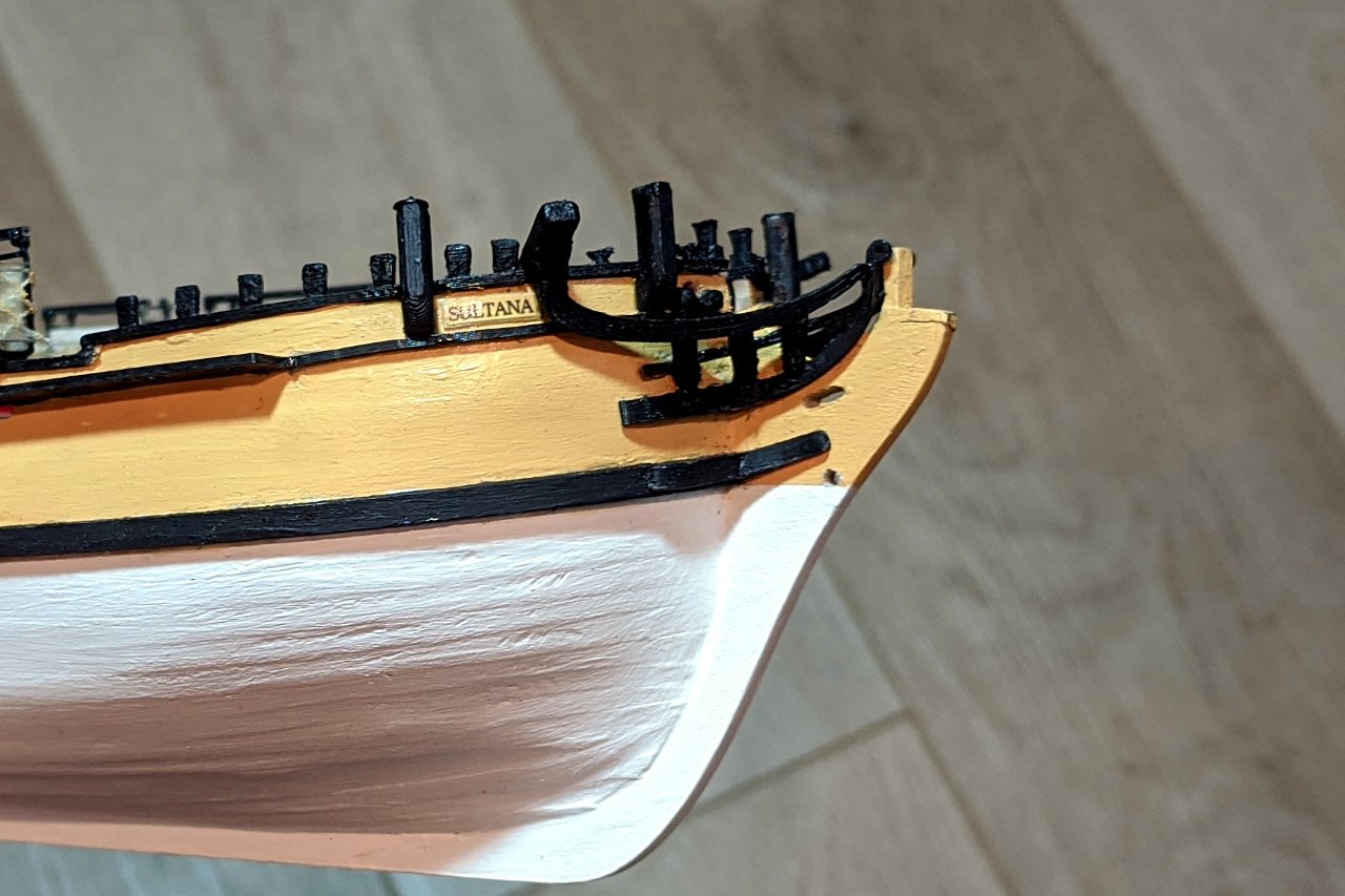
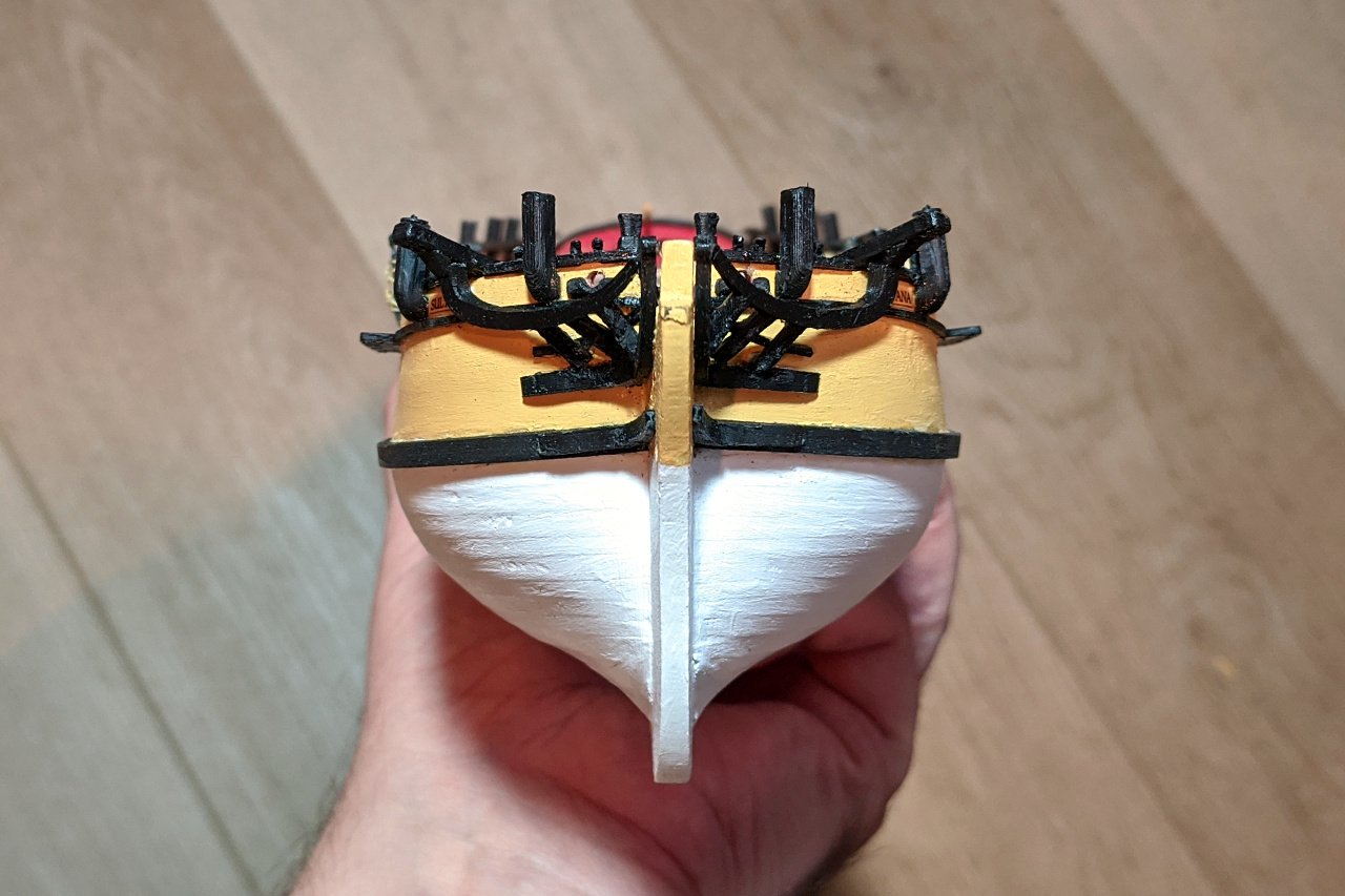
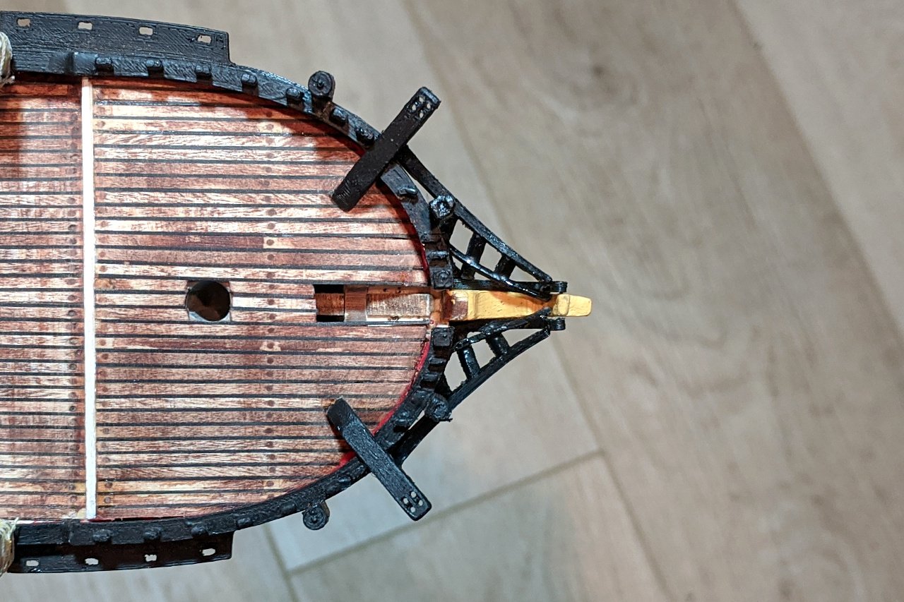
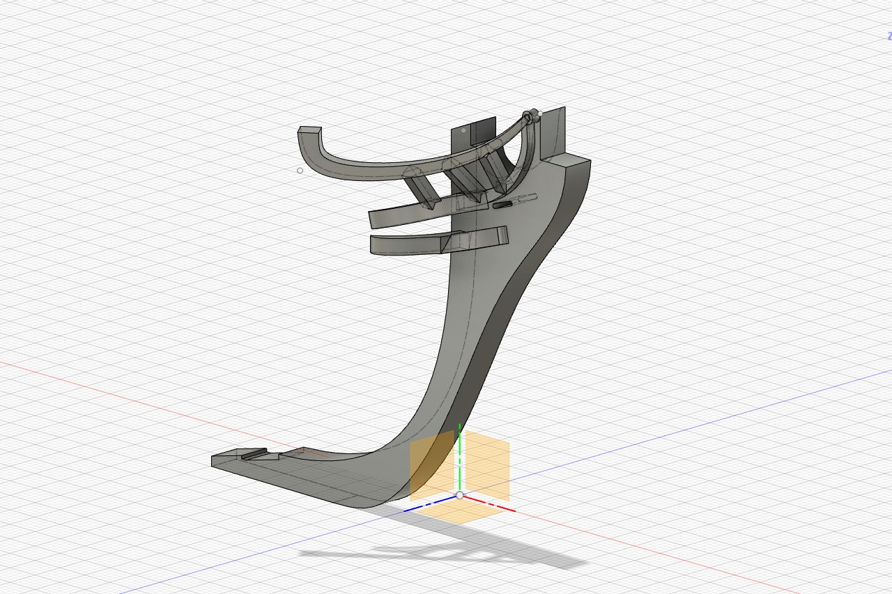
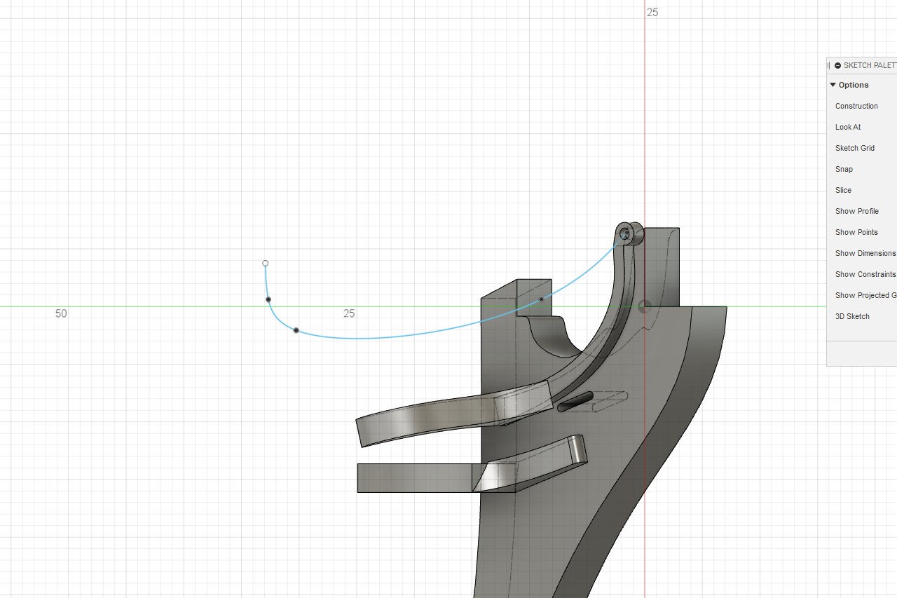
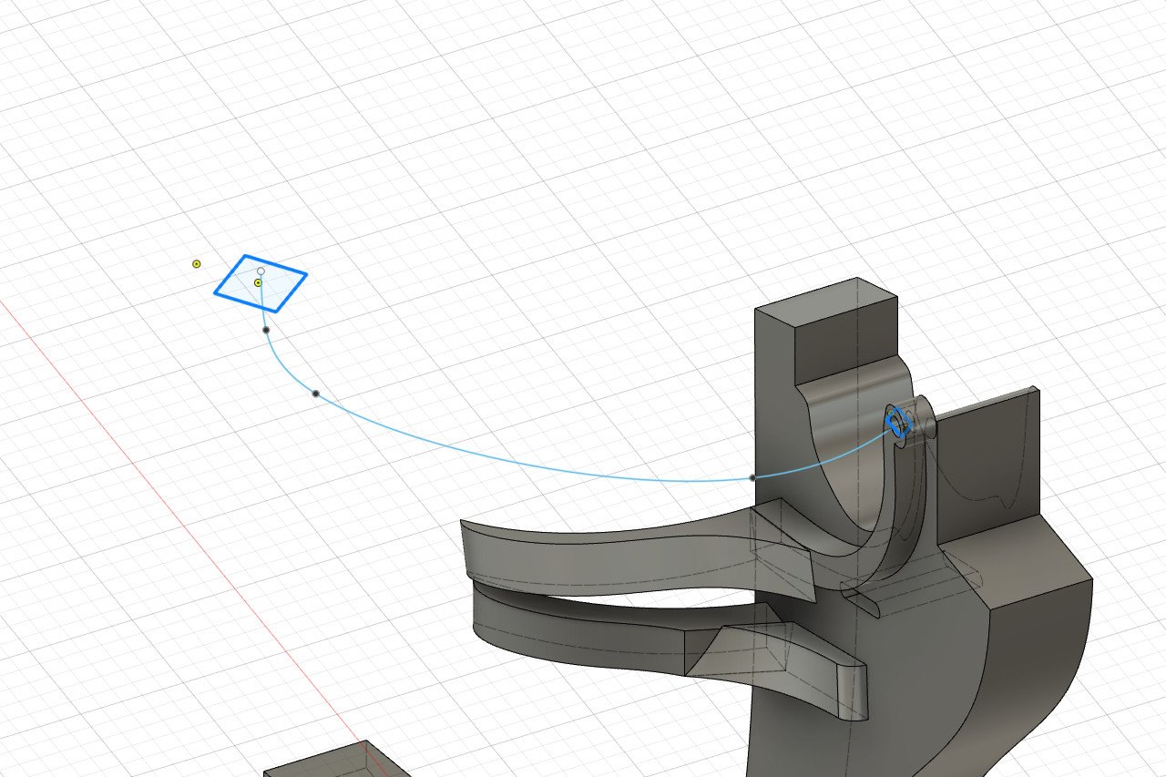
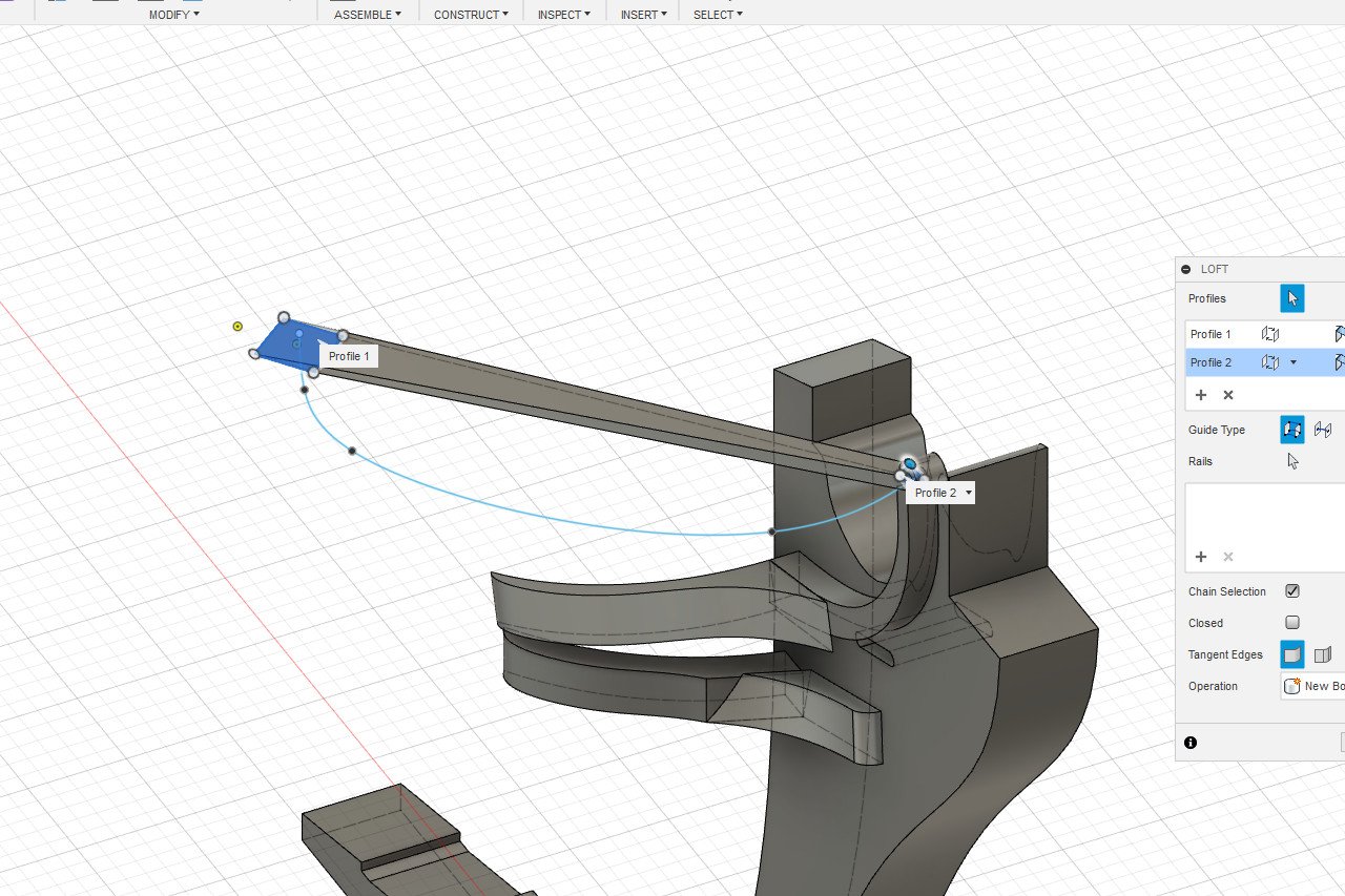
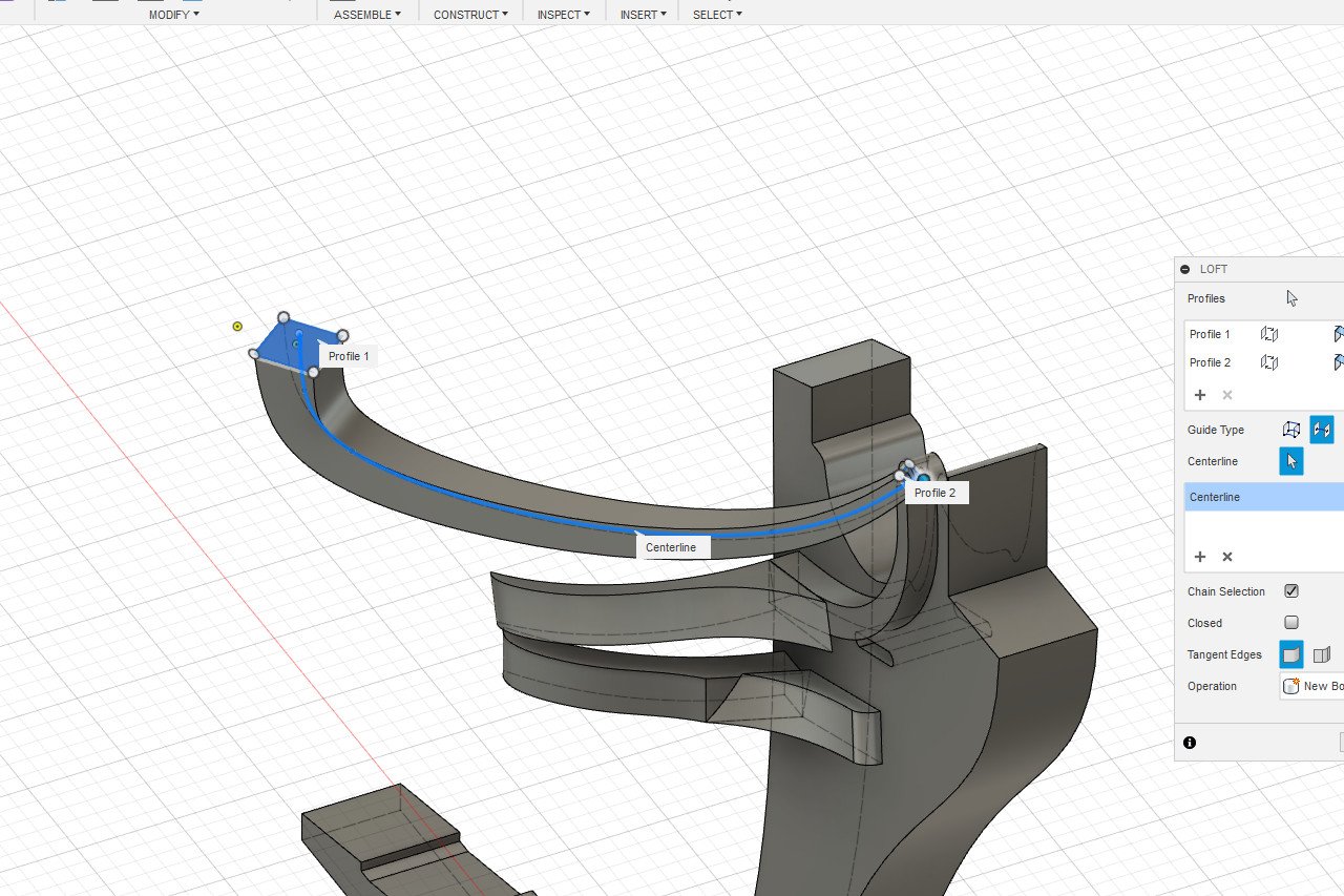
I have completed the head rails, head timbers, and cheek knees. I found it best to work on the cheek knees first, and head rails last. It was necessary to make several parts in multiple pieces, as the shapes were too complex to model as one. I also attached the printed nameplate to the outer bulwarks. Here is the 3D design for the various 3D printed parts. For the curious, here is how I created the shape of the headrail in Fusion 360. I started by creating a construction plane which passes through the underside of the cathead at one end, and through the stem at the other. On this plane, I created a sketch and drew the curve of the headrail. This curve passes through the center of the eventual part. Next, I created two construction planes. The planes are tangent to each end of the headrail curve. On the planes, I created the start and end shapes for the cross-section of the headrail. In this case, a 3mm x 3mm square at one end and a 1mm x 1mm square at the tip, highlighted in blue below. To create a shape, I used the loft tool. Initially, the loft connects the two profiles via a straight path. In the loft dialog, I changed the guide type from tails to center line. I selected the headrail curve as the centerline, and the curved shape is created as I wanted it.
- 222 replies
-
- 4
-
-
- sultana
- model shipways
- (and 1 more)
-
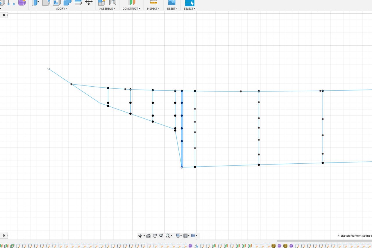
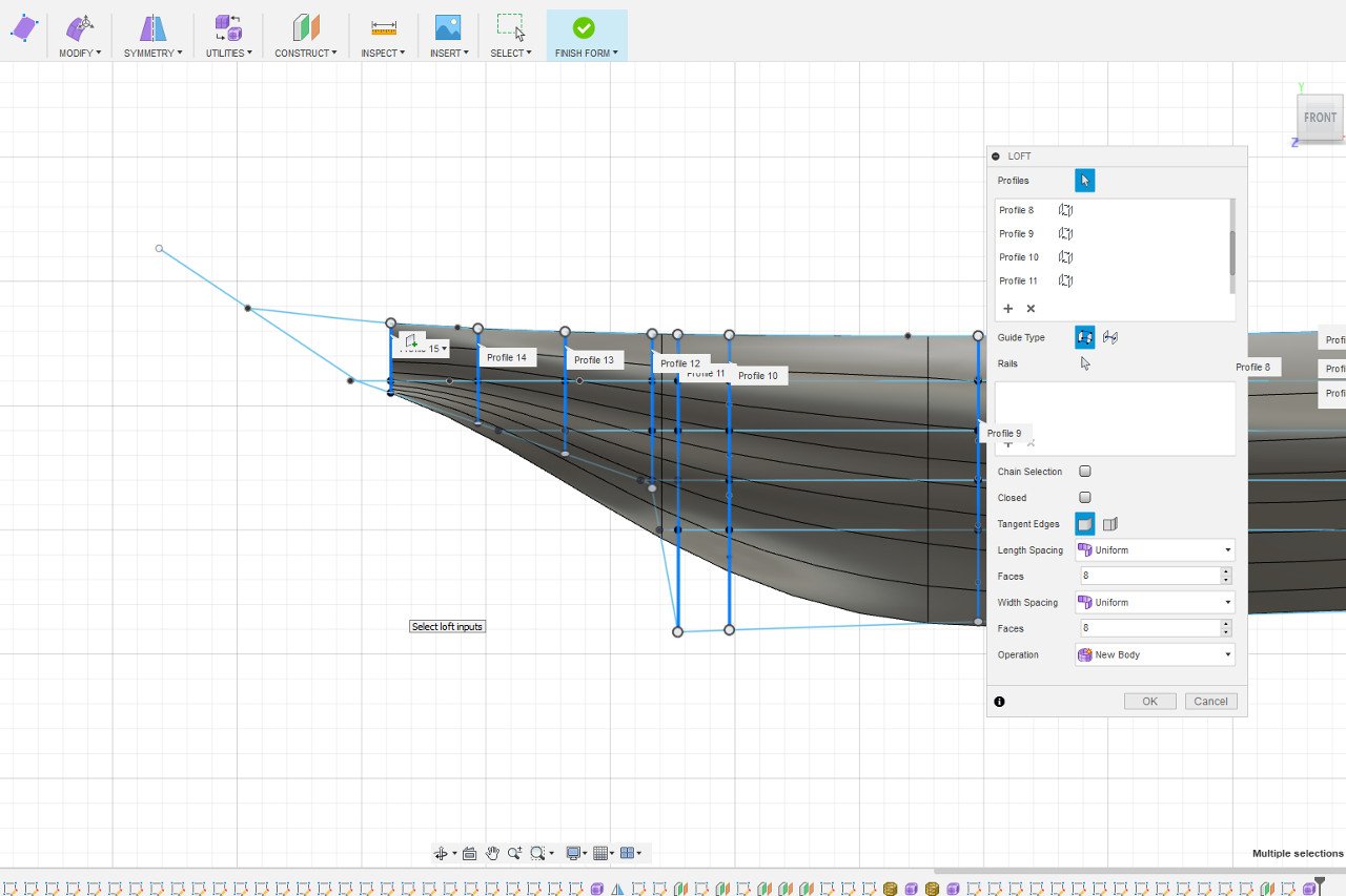
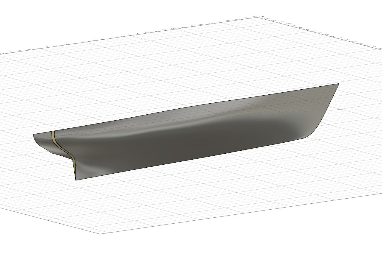
Interesting idea. I think you mean a new station as shown below by the thicker blue line. If I try a direct loft across all the stations, it doesn't work. My keel is made of multiple lines, so it can't work as a rail, and not all waterlines pass through all stations, so they can't be used as rails. However, I get some good results from three separate lofts. Curiously, the direction of the normals is not consistent between each of the lofts, but the resulting surfaces are usable.
-
I drilled the hawseholes and added reinforcement pieces on the outside and inside of the bulwarks around the holes.
- 222 replies
-
- 2
-
-
- sultana
- model shipways
- (and 1 more)
-
Thanks, Matt. If you look back at older pictures, my deck was much darker. I sanded it down to lighten it up, and fortunately, it ended up with a good weathered look. Now the question is whether I should move on to the bits I really want to do (all the stuff on the deck), or the bits I don't want to do (headrails and figurehead)...
-
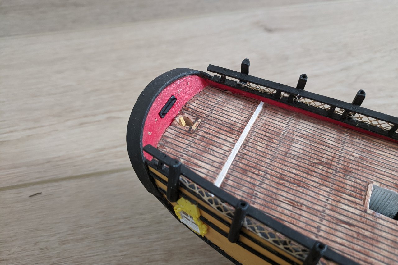
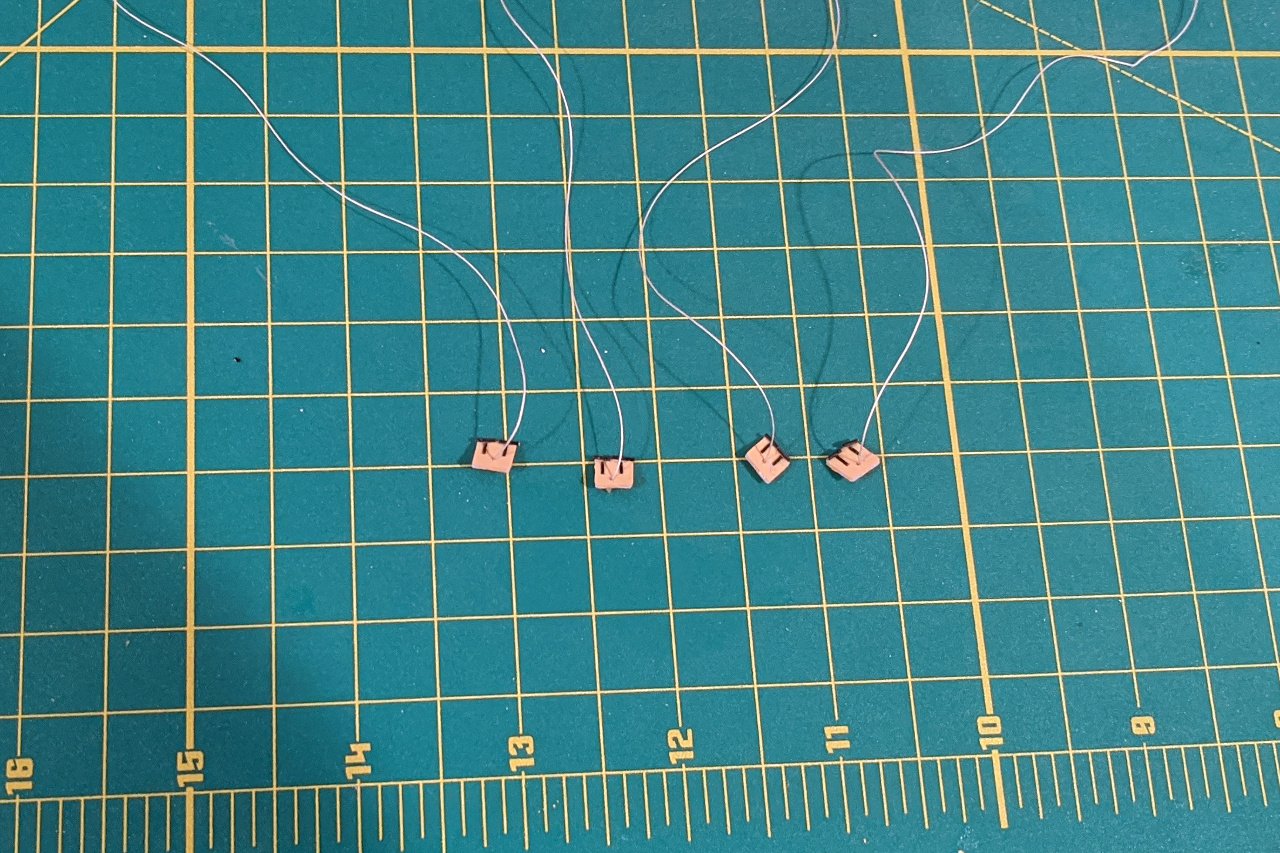
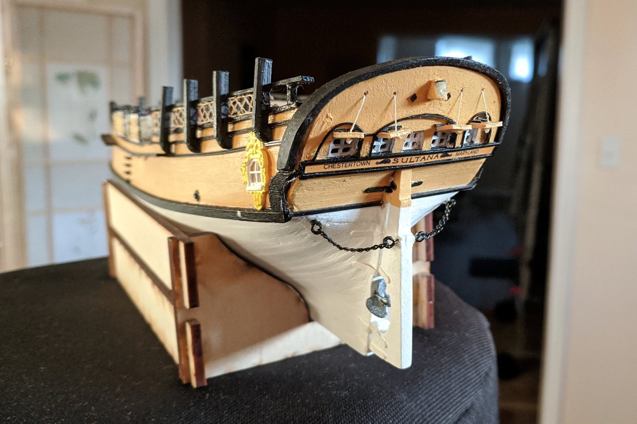
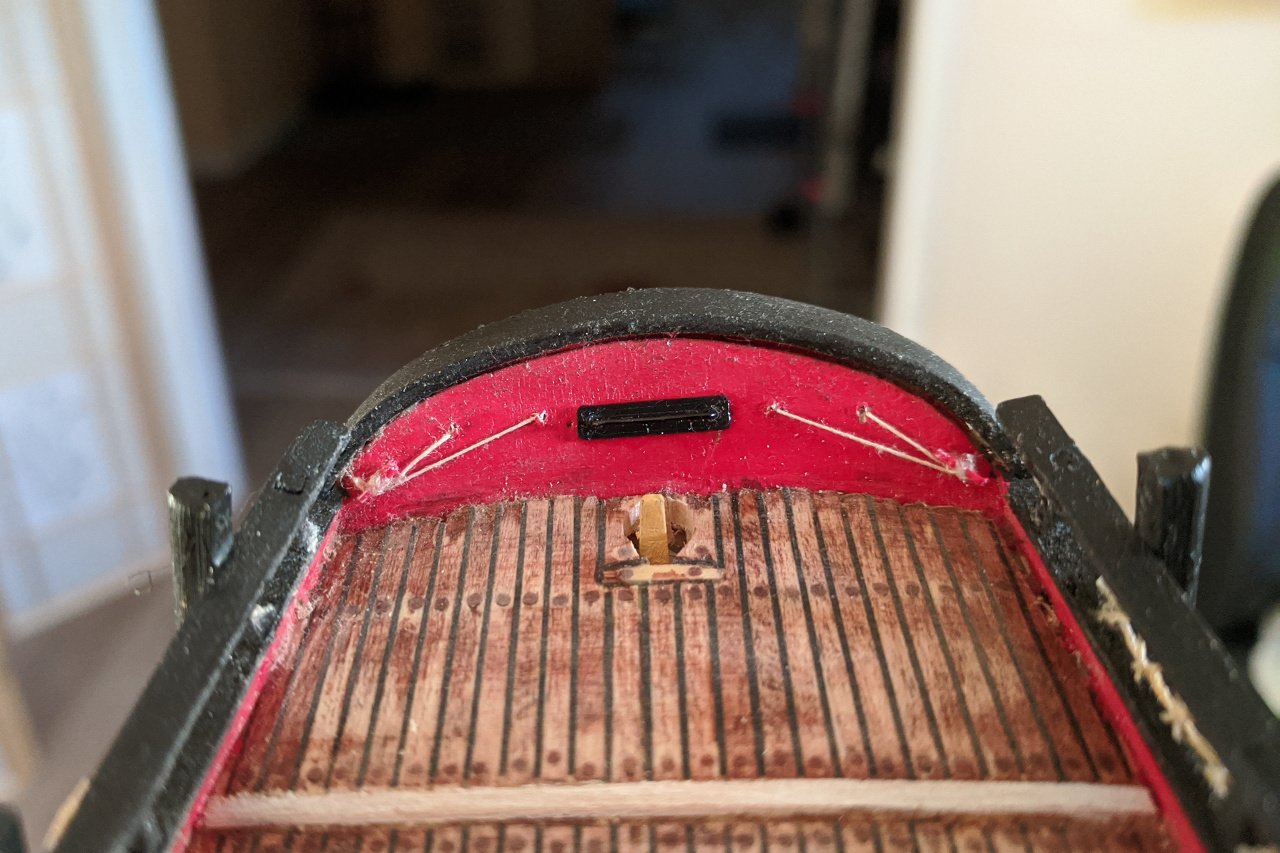
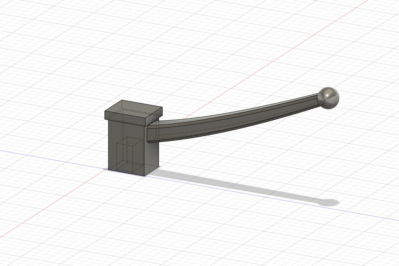
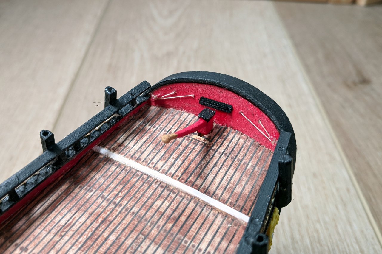
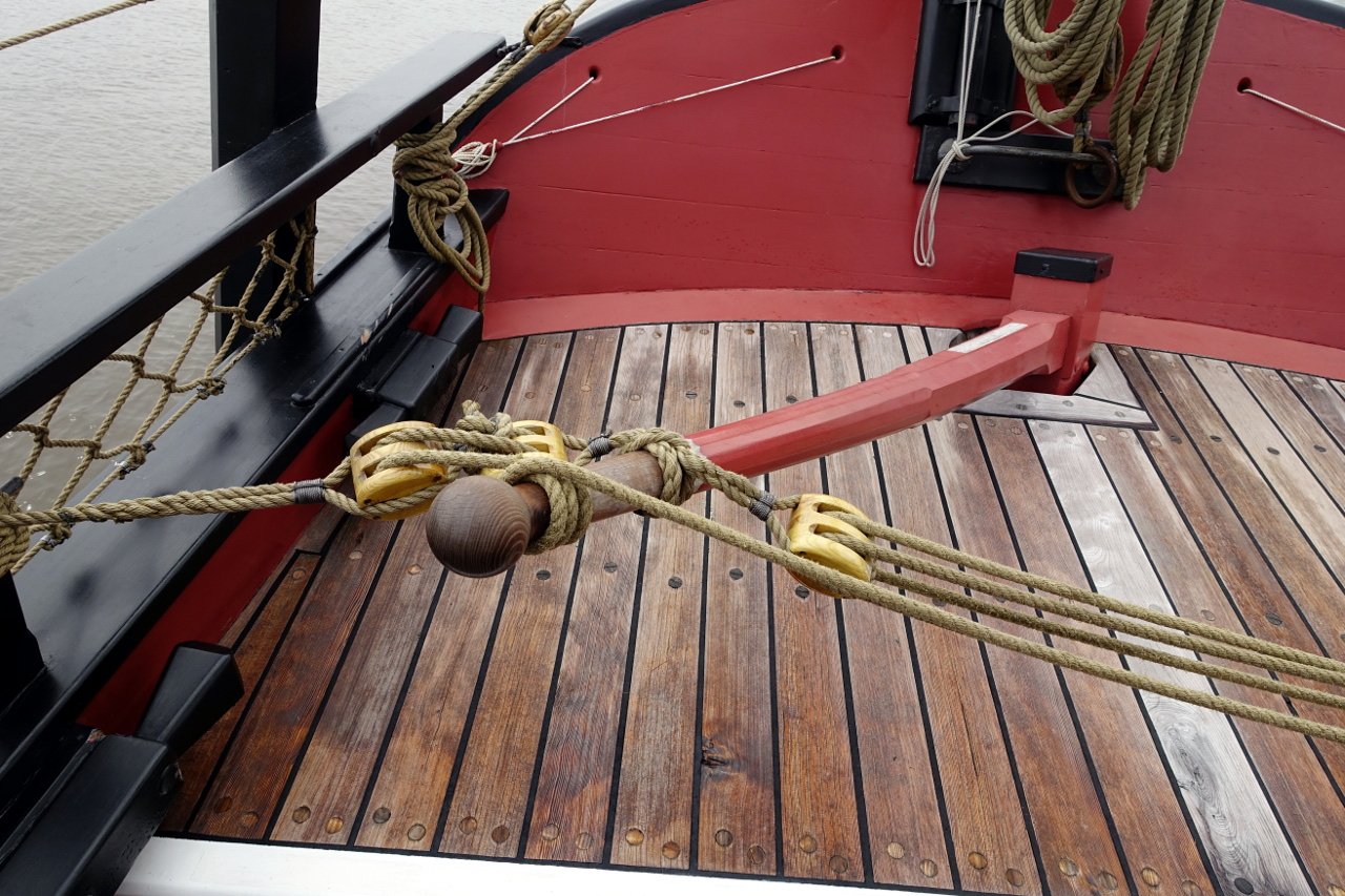
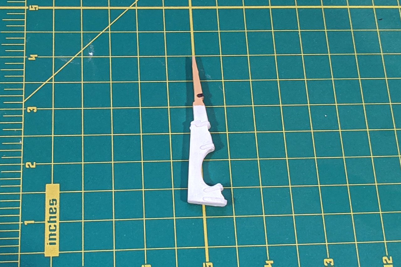
With the rudder in place, all it needs is the tiller to be complete. However, it will be difficult to work on several final features of the transom with the tiller in place, so those need to be completed first. Of those, the first is the boom sheet traveler, with a black plate behind it. You can also see the holes that were drilled for the window cover ropes. The transom windows were laser cut, so I already had their exact shape an size from the laser cut template. From that, I was able to produce the window covers in the correct size. Hinges were added in black, and the rope was threaded through each window cover. Here are all the window covers in place. I also added the lamp, whose "glass" was made by building up layers of clear glue. The small diamond shapes next to the lamp, both here on the model and on the real ship, exist to hide where the ends of the boom sheet traveler puncture the transom. On the other side of the transom, the ropes are tied off on two very tiny cleats. Finally, I can make the tiller. Here is the 3D design. The tiller was 3D printed, painted, and installed on the ship. Here is a photo I took of Sultana's tiller
- 222 replies
-
- 5
-
-
- sultana
- model shipways
- (and 1 more)
-
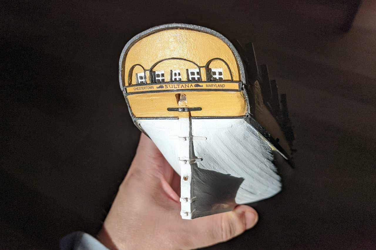
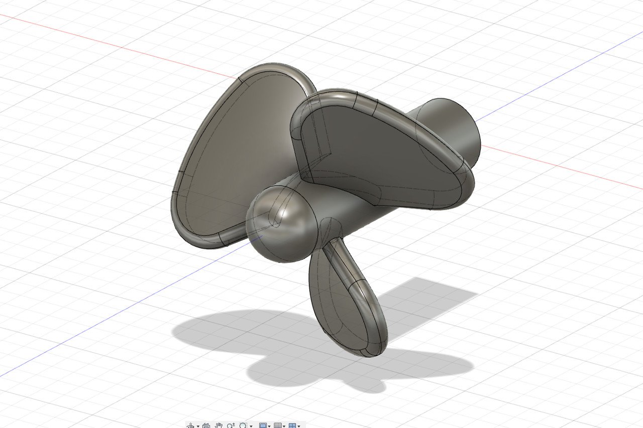
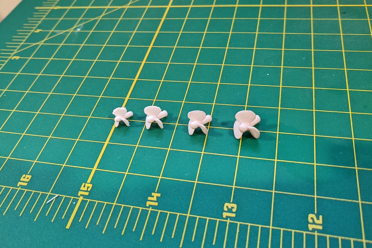
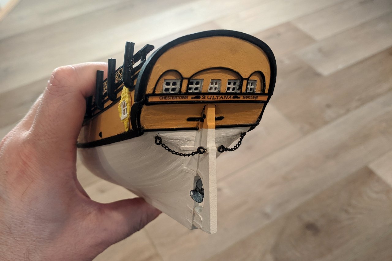
Strips for the pintles were added to the rudder. I determined that, at this scale, pins were not needed and would be hidden from view anyway, so they were omitted. The gudgeons were added to the hull. After watching a few tutorials, I managed to create a reasonable propeller in Fusion 360. I wasn't sure what the right size would be to fill the space, so I printed it in several sizes. The rudder and propeller were glued into place, and the rudder chains were attached. Here is my reference photo for the rudder, found on sultanaeducation.org.

- 222 replies
-
- 5
-
-
- sultana
- model shipways
- (and 1 more)
-
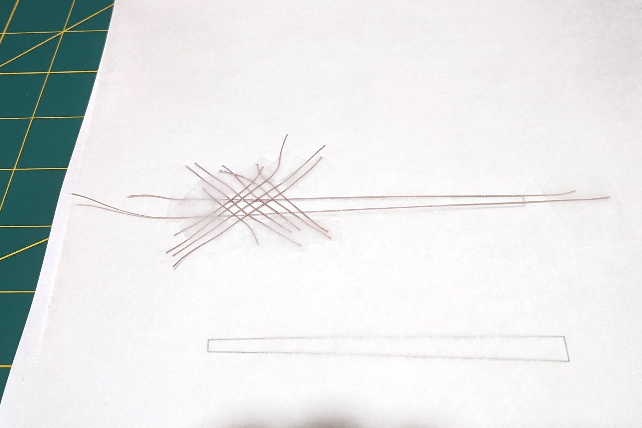
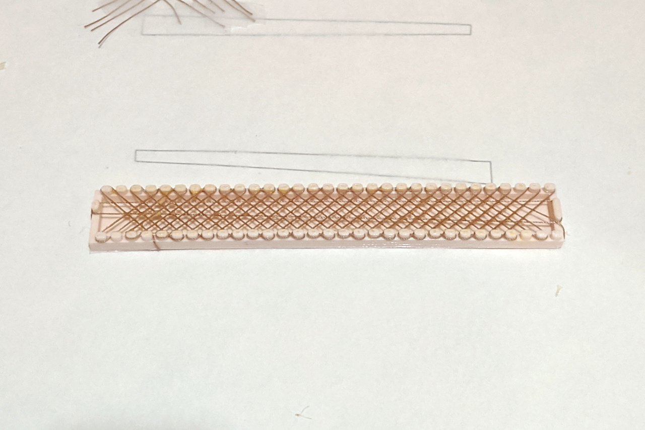
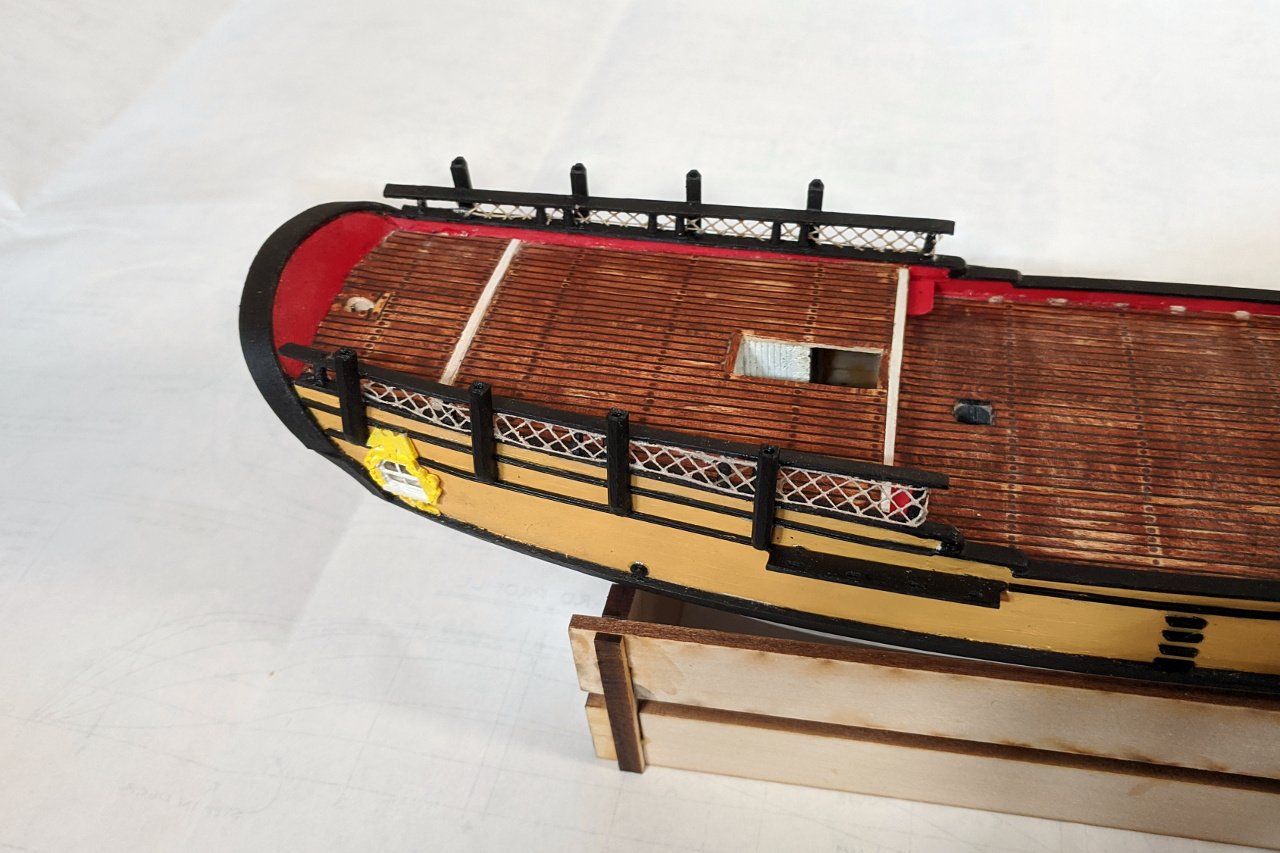
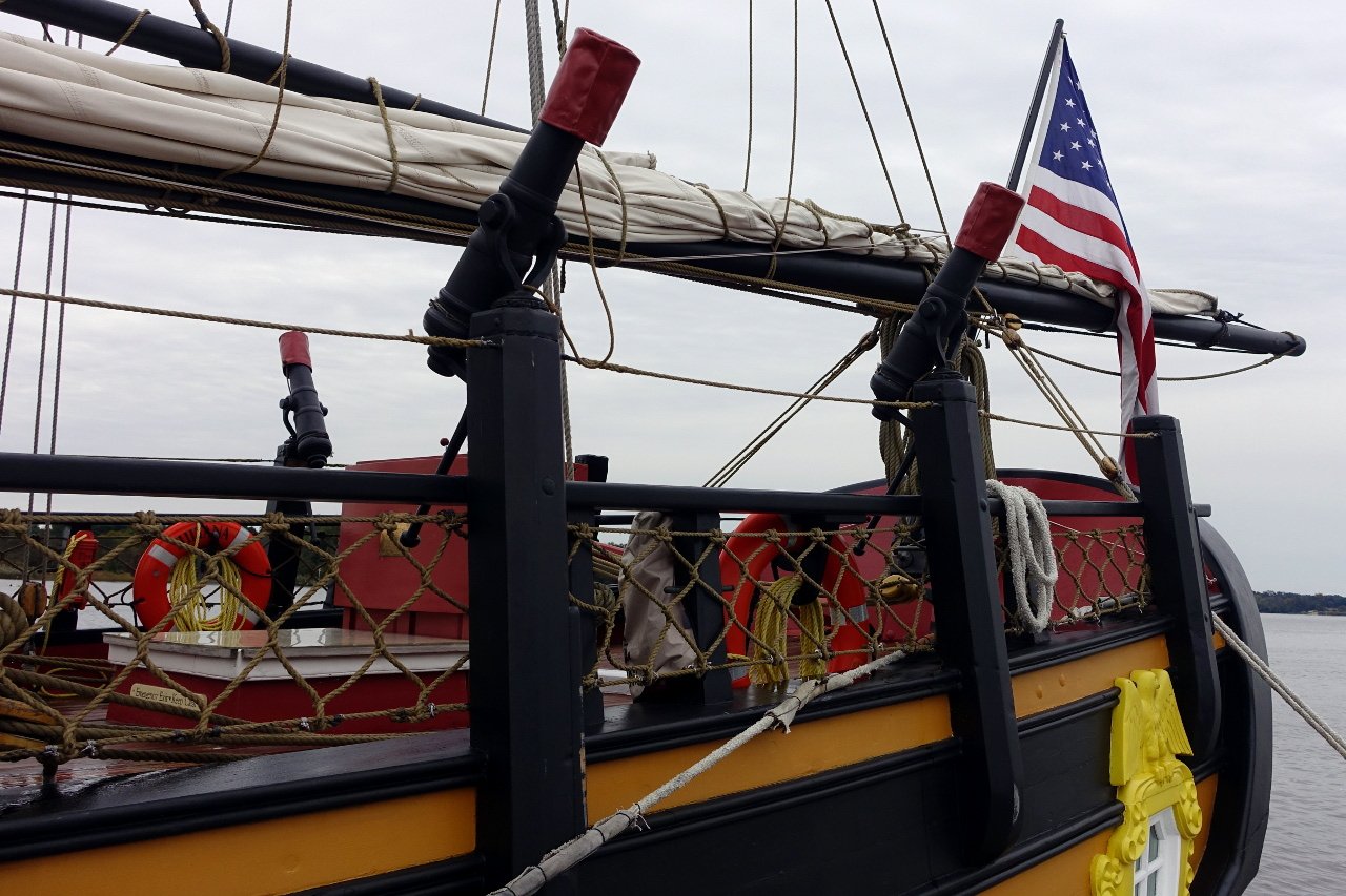
There is netting along the aft railings of the Sultana. My first thought was to use some tulle. However, the scale was wrong, and the tulle was too thin and light, barely noticeable. I tried painting the tulle to darken it and thicken the strands, but the paint failed to adhere. It was clear that I would need to make my own netting from thread. My next attempt started by trying to form netting from individual strands of thread, which I would saturate with glue to hold them together. You can see how far I got below. It was immediately clear that I didn't have the patience for this method, and the mesh would be uneven. Of course, there is a 3D printed solution to every problem. I 3D printed a jig to use for forming the netting. Then glue was applied to hold it all together. And the netting was put on the ship. Also note the deck steps which were added around the same time. Here's a reference photo I took which shows the netting. Mine is a little lighter in color, but acceptable.
- 222 replies
-
- 6
-
-
- sultana
- model shipways
- (and 1 more)
-
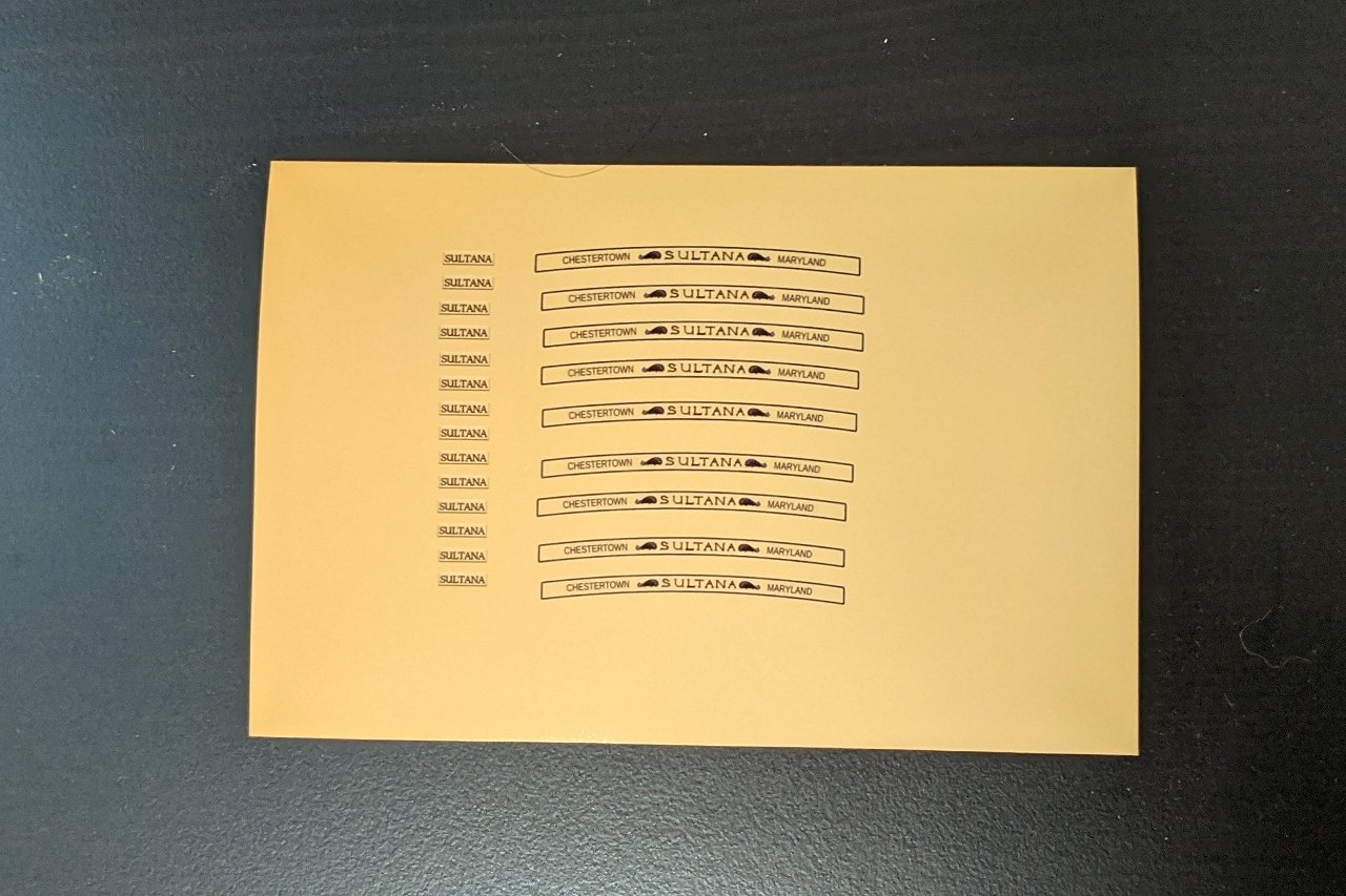
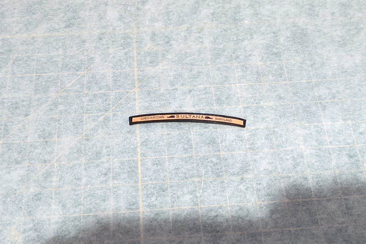
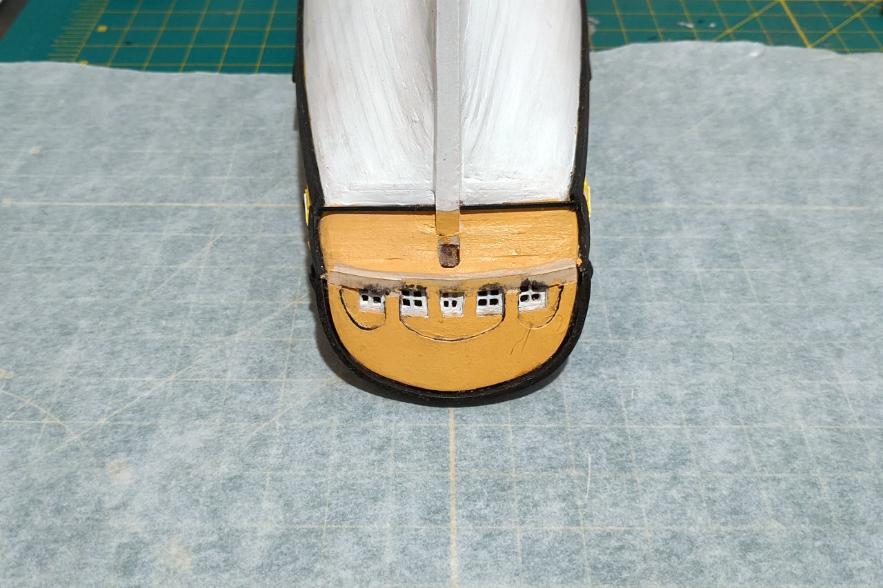
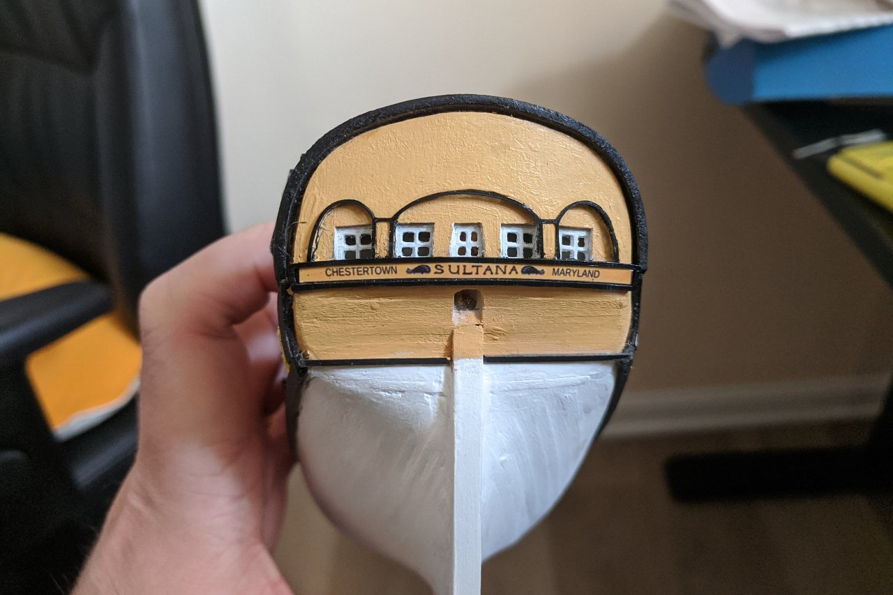
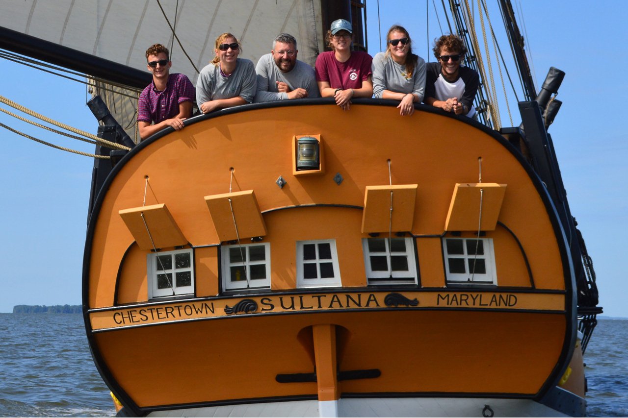
Here is the template I used to laser cut the window overhang on the stern. By using the lines on that template, I was able to create a pattern for the black trim around the windows. The 3D form is below. This was printed on my 3D printer. I also created a form for the area below the windows. I designed and printed out the lettering on photo paper. I wasn't sure exactly how large it should be, so I created a set of images in varying sizes. The images on the left will be used later for the nameplate on the bow. The lettering was cut out and glued to the shape that will go below the windows. It was necessary to trim away some of the wood below the windows so that the shape would fit properly. And this is the result, with the pieces glued on. Some touch-up of the paint will be needed. And this is a reference photo from sultanaeducation.org showing the stern. I will need to add the window covers and the lamp, but I think I will save that for later. If I added them now, they will be in danger of breaking off while I work on other parts of the ship.
- 222 replies
-
- 6
-
-
- sultana
- model shipways
- (and 1 more)
-
Swivel gun stocks were designed. They were 3D printed at various heights as needed. In addition to the swivel gun stocks, the steps on the side of the hull and the round drainage hole were also made. The picture below shows everything glued in place.
- 222 replies
-
- 7
-
-
- sultana
- model shipways
- (and 1 more)
-
The design and 3D printing of parts continues. This time, it's the channels. After some experimentation, I made them a little bit larger than what appears on the plans. The tabs were added as an aid in attaching them to the hull. Here are the pieces after printing. I also printed long strips, 1mm x 1mm, to use as the trim. Note how the channels and trim are merged.
- 222 replies
-
- 3
-
-
- sultana
- model shipways
- (and 1 more)
-
I was fooled too. What incredible work. I am looking forward to seeing more. In particular, I would like to see the method for developing the hull shape from the plans.
-
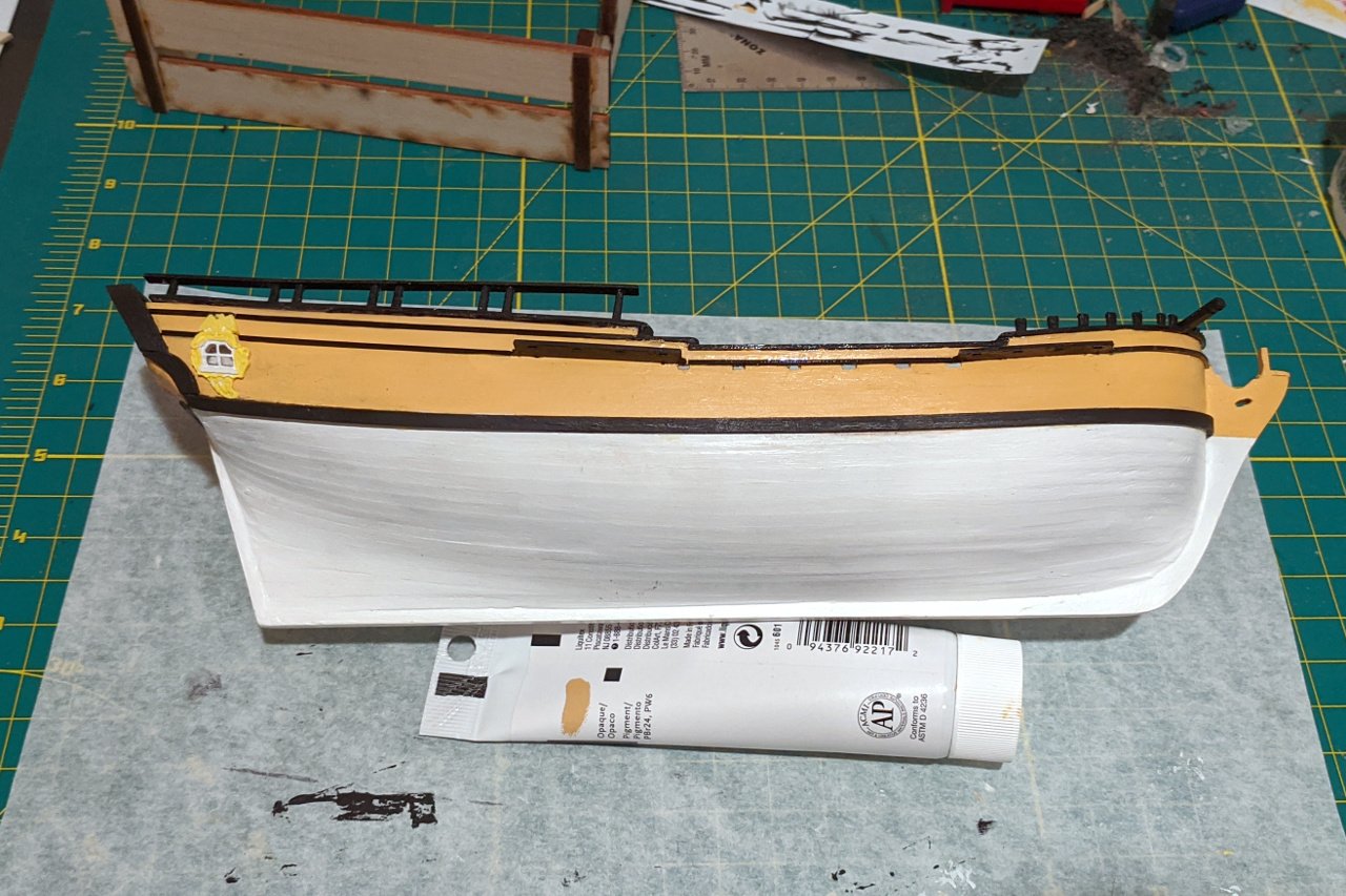
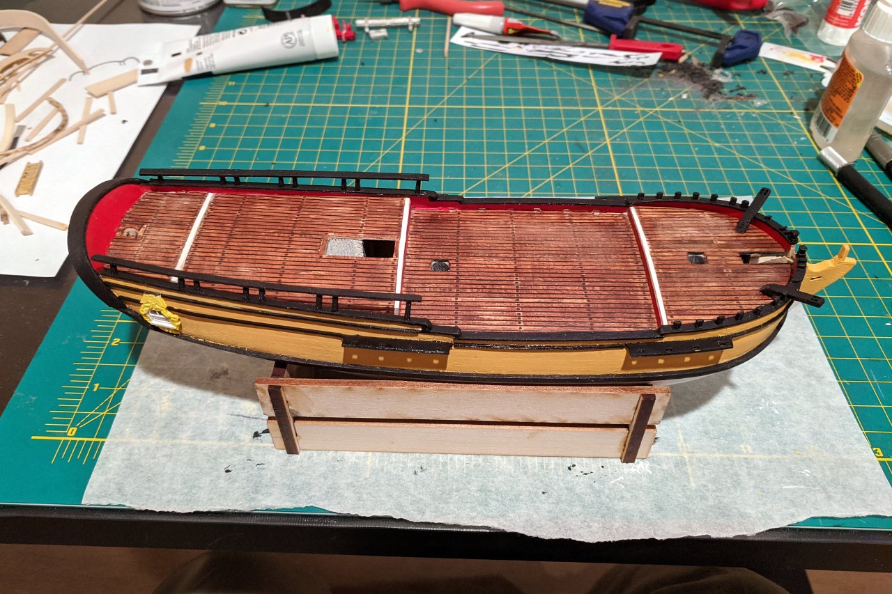
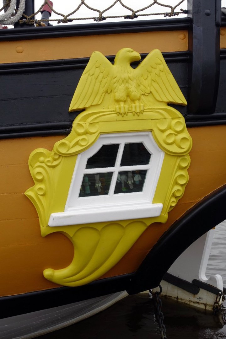
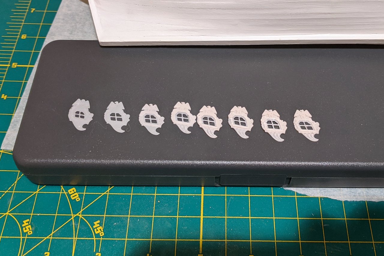
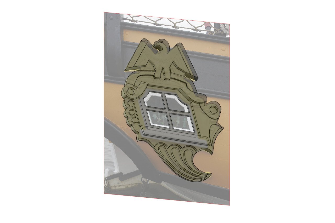
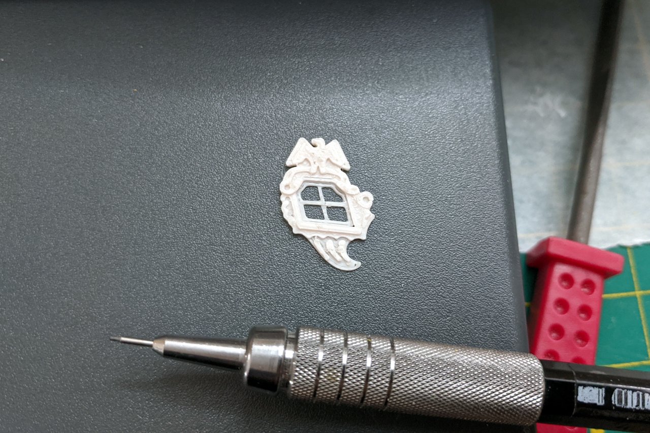
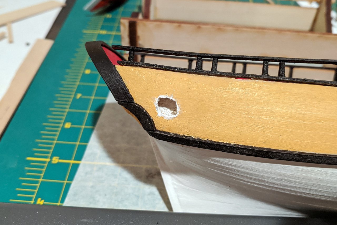
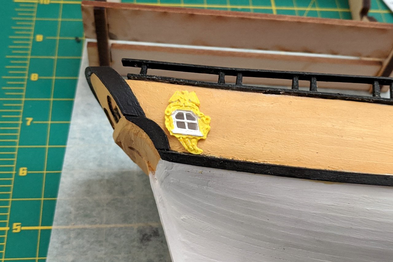
Time for the quarterbadges. Here's a nice big picture I took last year of the Sultana's quarterbadge. Initially, I thought I would model this in Fusion 360's T-Spline modeling area. However, that proved to be beyond my abilities with the software, and ultimately, not necessary at the scale at which I'm working. The quarterbadge form pushes my 3D printer to its limits. In the end, the best approach was not to try to model the quarterbadge form perfectly, but to arrive at a shape that would create the best badge based on the limited ways the 3D printer would produce each layer. I started simply by creating a single layer object to establish the general outline of the shape. From there, I gradually built up each form of the badge. The picture below shows the evolution of the design. The following pictures show my final 3D design and the corresponding 3D printed part. The mechanical pencil is included for scale. When I designed the bulkheads for the model, I intentionally made sure that there would be empty space inside the hull at the location of the quarterbadges. In fact, if you go back to my post of 20 March, you can see on the last picture that I painted that area white before planking over it. All of that was for the purpose of having the interior visible through the quarterbadge windows. I carefully broke through the planking and exposed the cavity. My design wasn't perfect, and some bulkhead wood also had to be filed back a bit. The cavity was given an extra coat of white paint. (The walls of the Sultana's cabin are painted white.) The quarterbadge pieces were painted yellow and white, and cellophane was glued to the windows as glazing. Then the quarterbadges were glued into place.
- 222 replies
-
- 7
-
-
- sultana
- model shipways
- (and 1 more)
-
FUSION 360 PROBLEM
SardonicMeow replied to AON's topic in CAD and 3D Modelling/Drafting Plans with Software
Derek, it took some searching (using the keywords startup / hobbyist), but I found the relevant page: https://www.autodesk.com/campaigns/fusion-360-for-hobbyists -
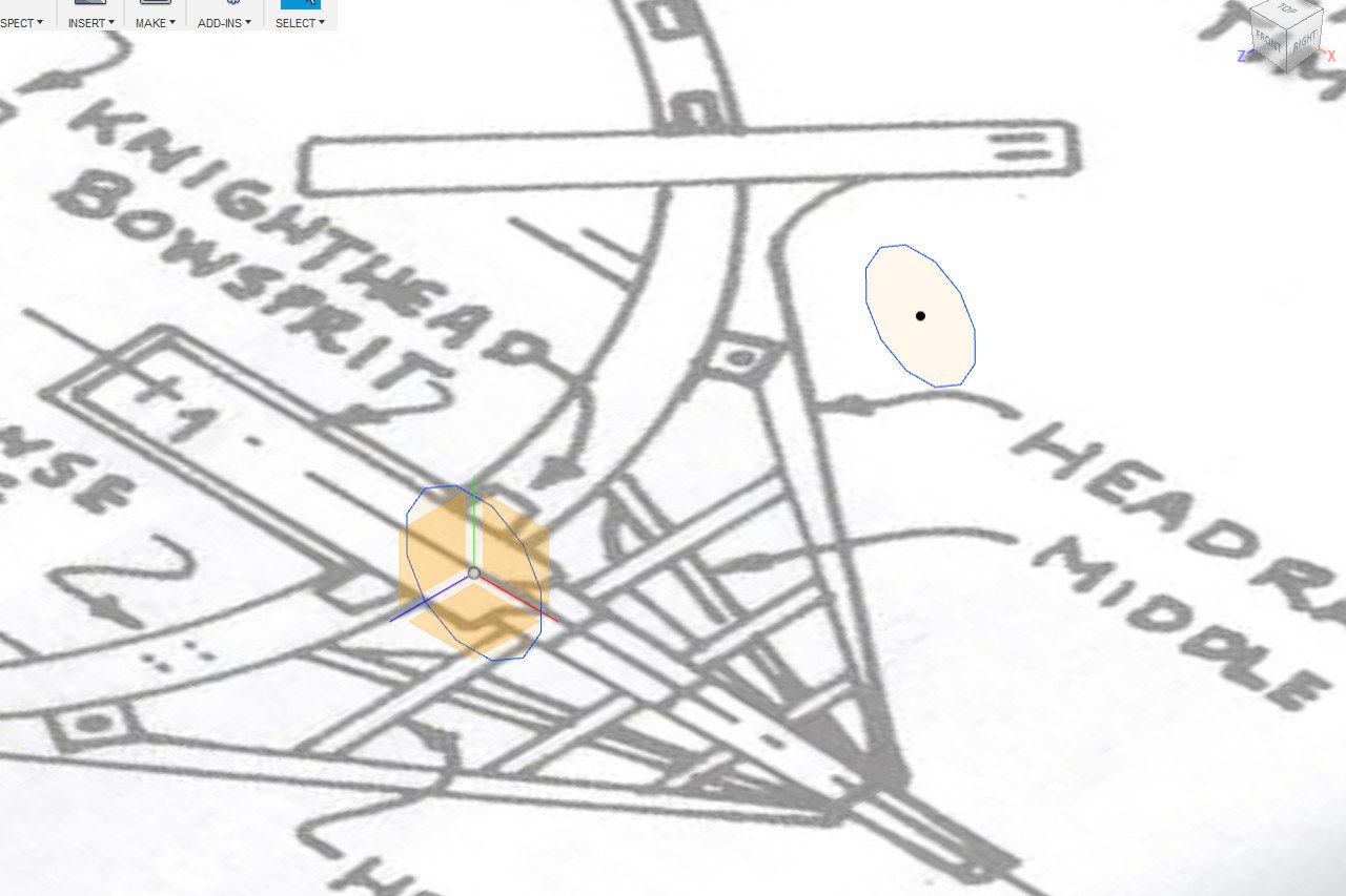
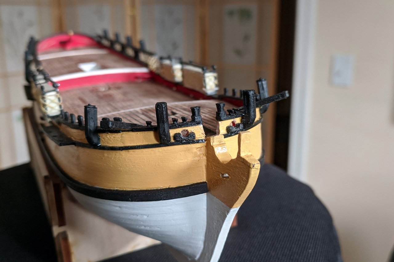
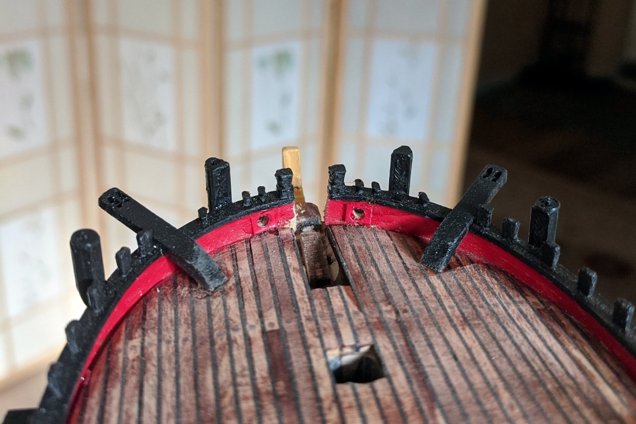
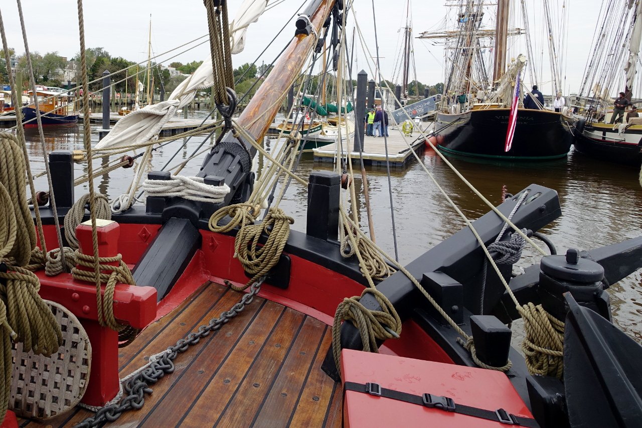
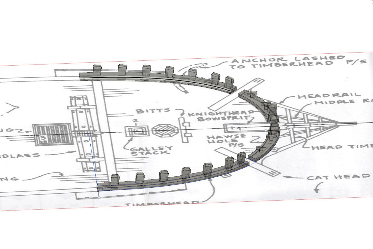
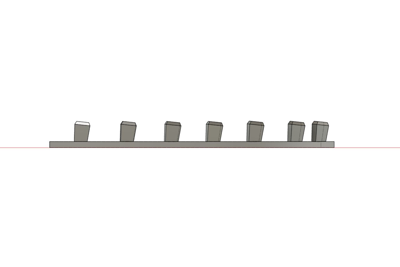
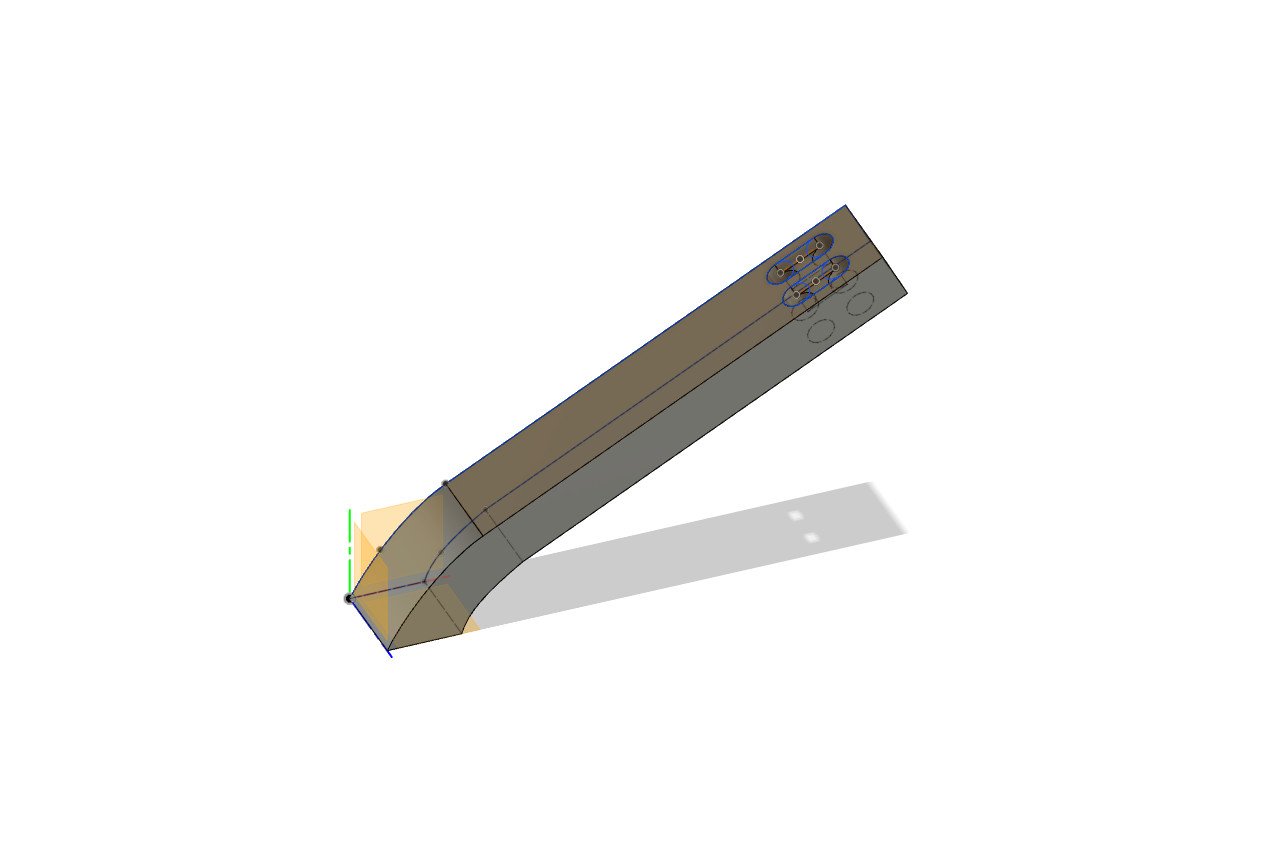
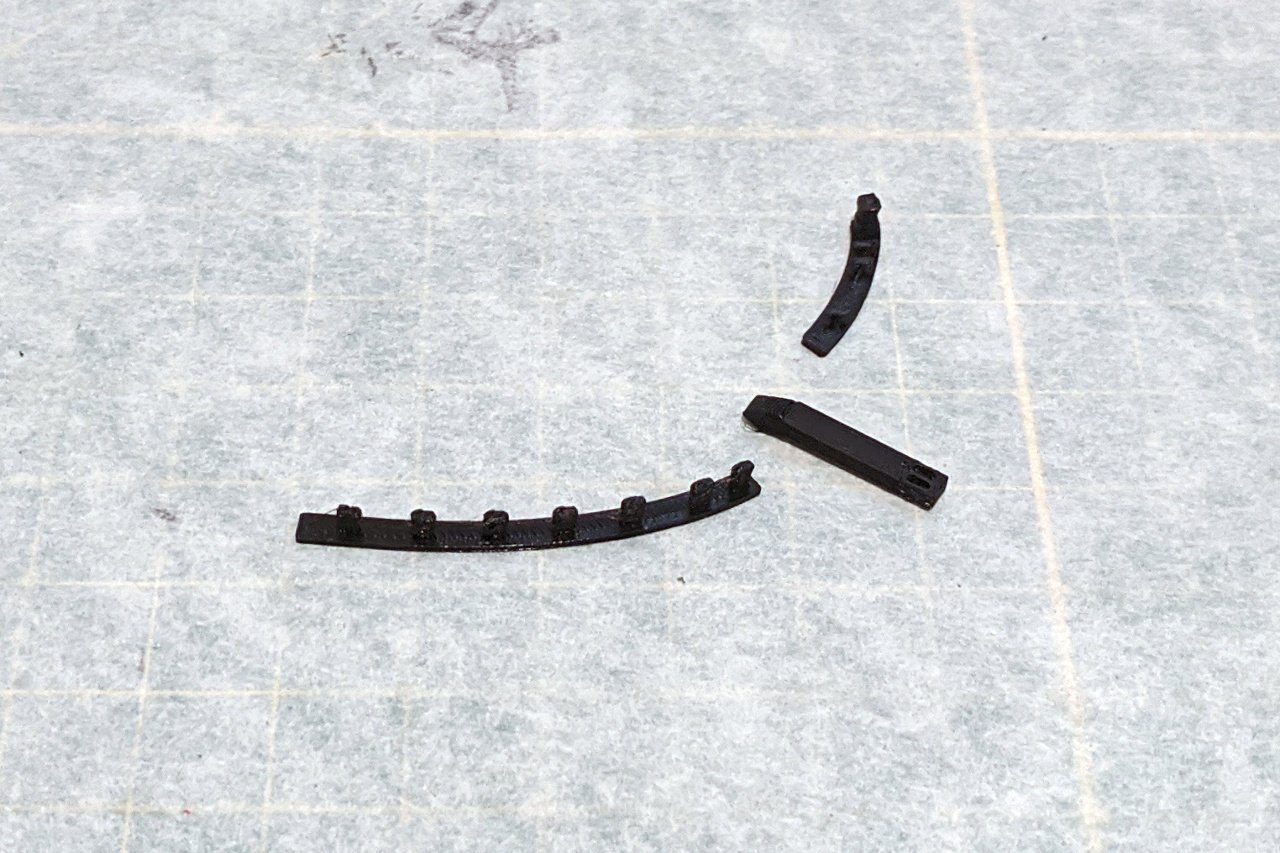
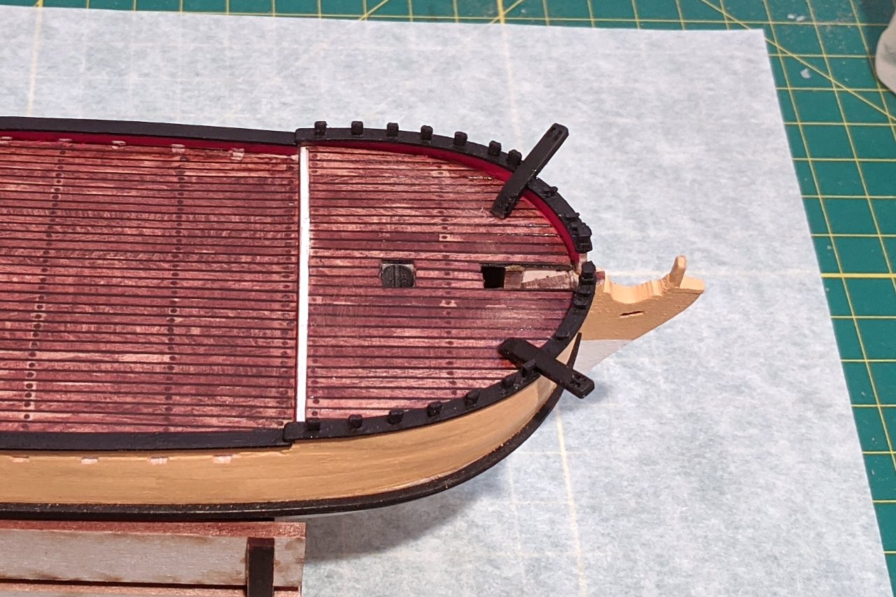
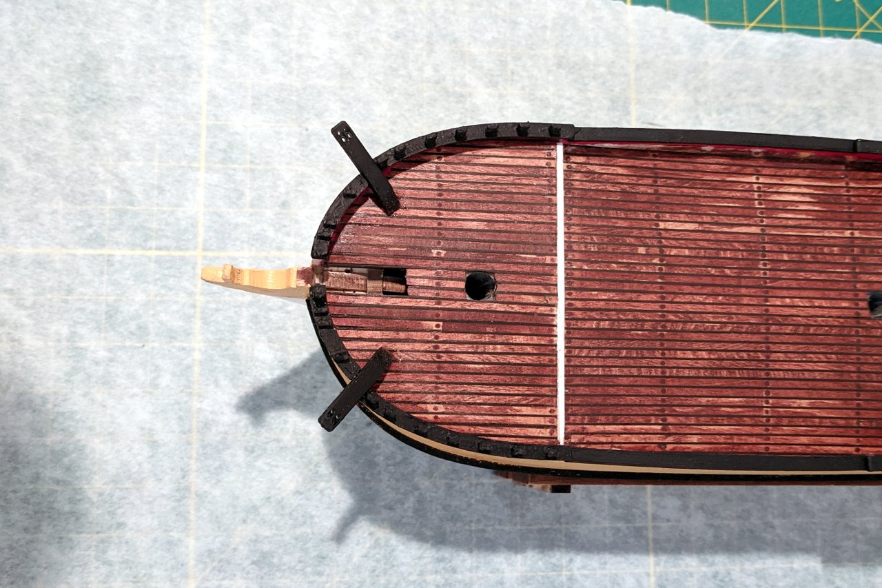
Here's a shot on the Sultana looking forward. The rails at the bow are somewhat complicated. The knightheads stand proud on either side of the bowsprit. Working along the rail, there are three cleats, then the rail is broken by the cathead. After the cathead, there are seven timberheads, which are wider at the top. This picture shows my final design for the forward rails. There were several iterations to get things where I was satisfied. This picture shows how the timberheads were angled to match the slope of the bulwarks. And this is the design of the cathead. All the pieces were 3D printed. Here are the pieces for the starboard side. All pieces were gently sanded and painted matte black prior to gluing. Two shots of the pieces after being glued.
- 222 replies
-
- 7
-
-
- sultana
- model shipways
- (and 1 more)
-
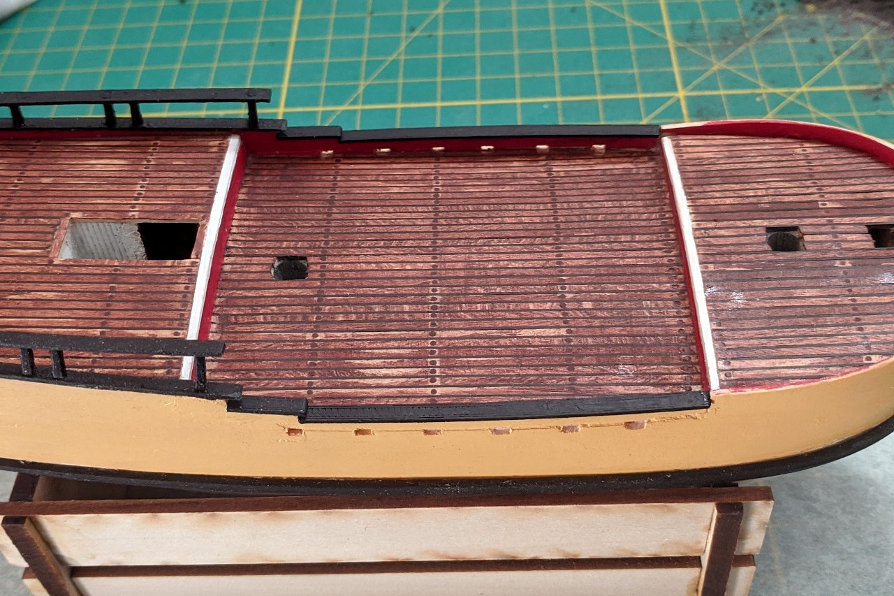
Just a small update today. I produced and glued the rails at the lowest level.
- 222 replies
-
- 3
-
-
- sultana
- model shipways
- (and 1 more)
-
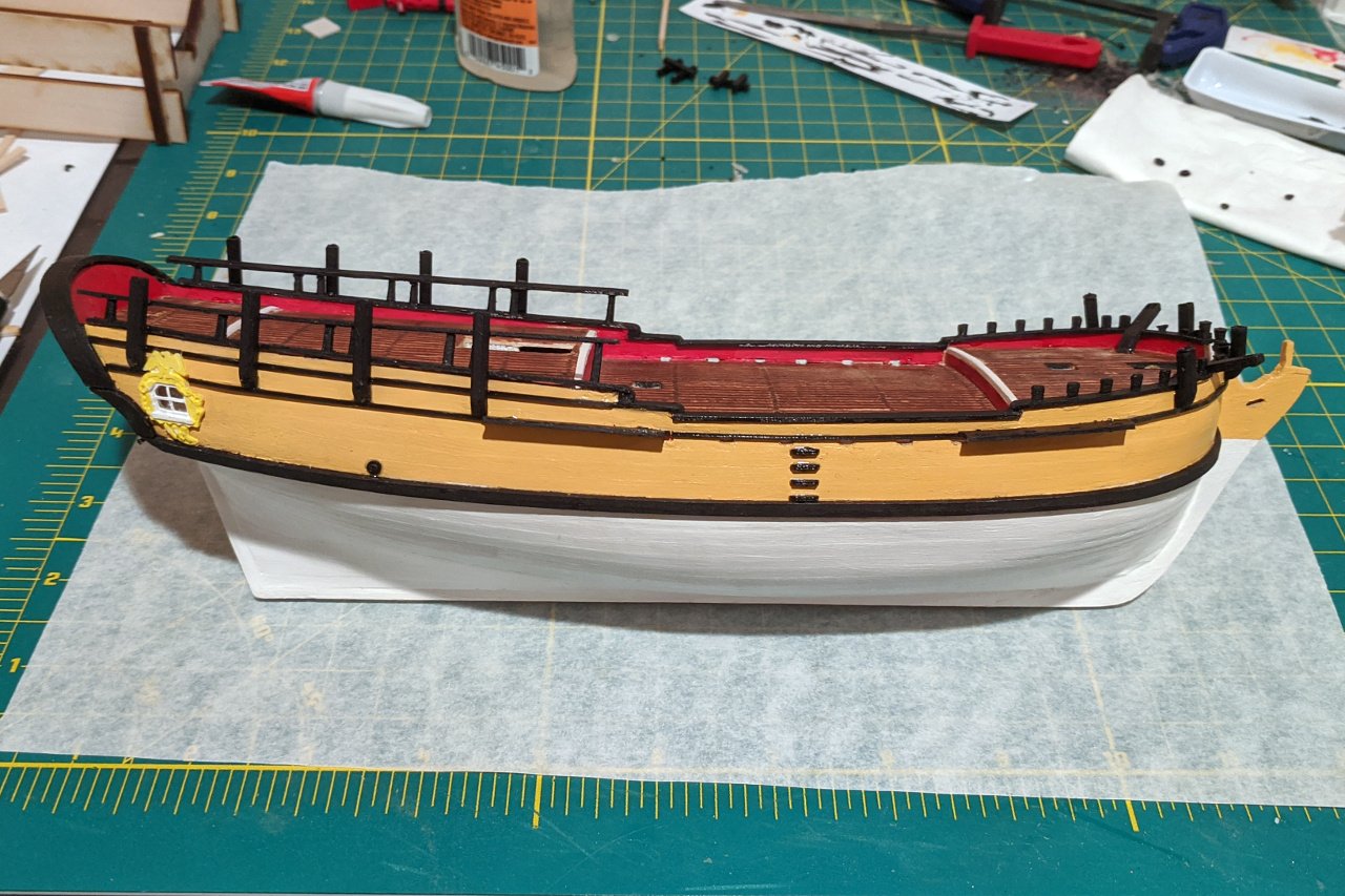
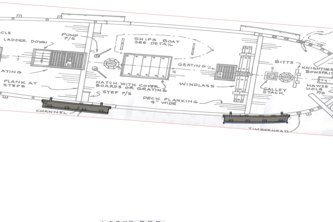
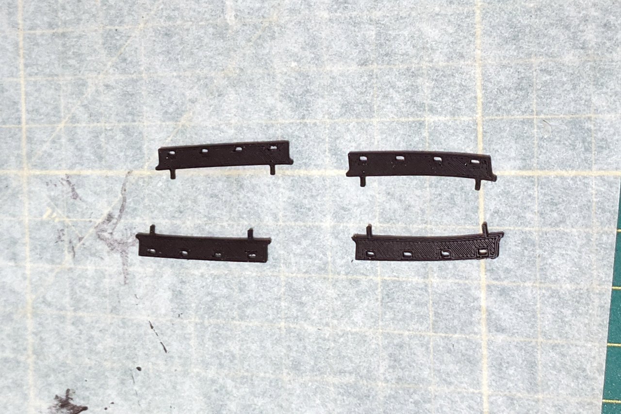
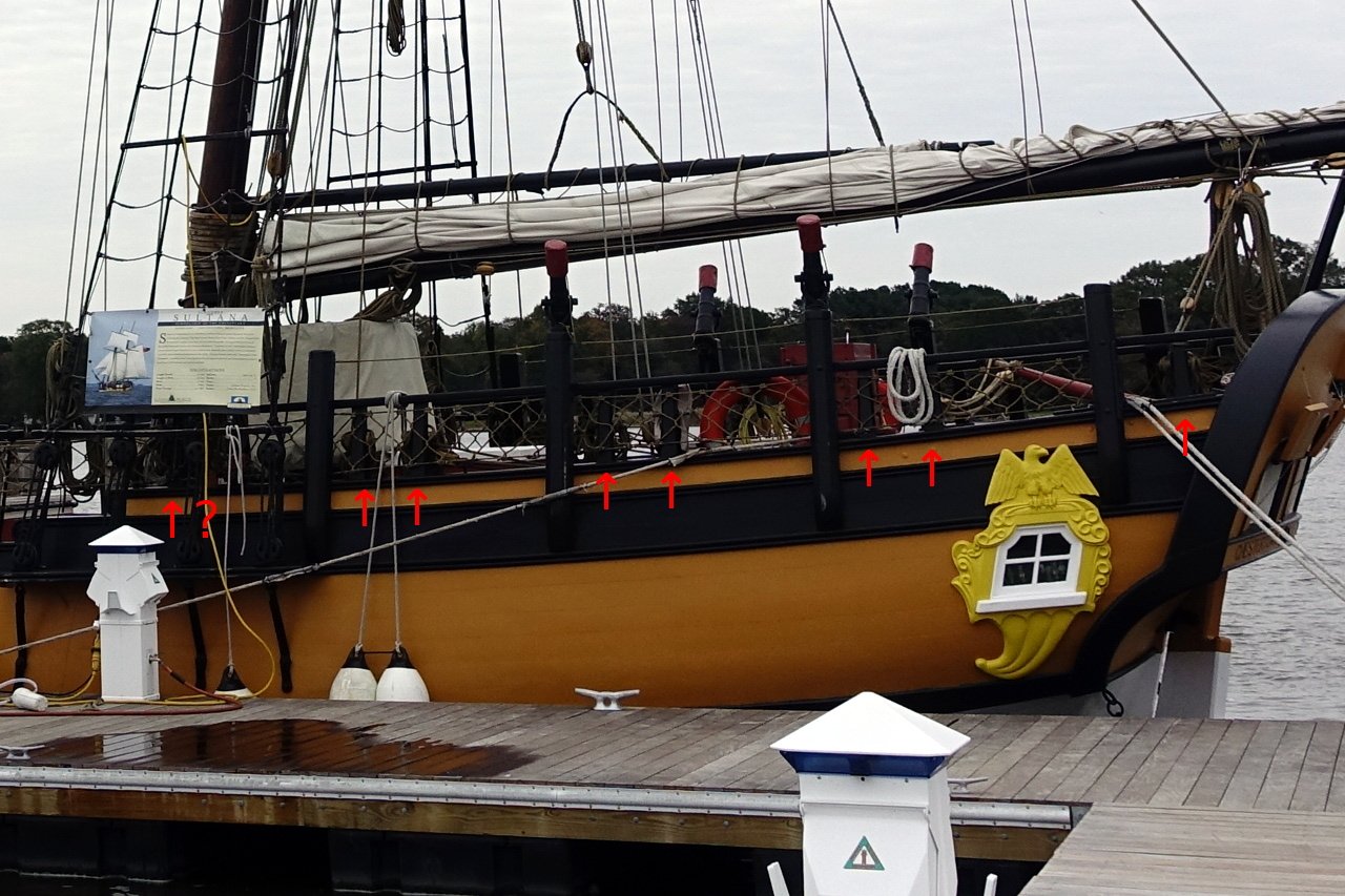
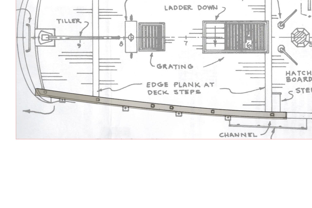
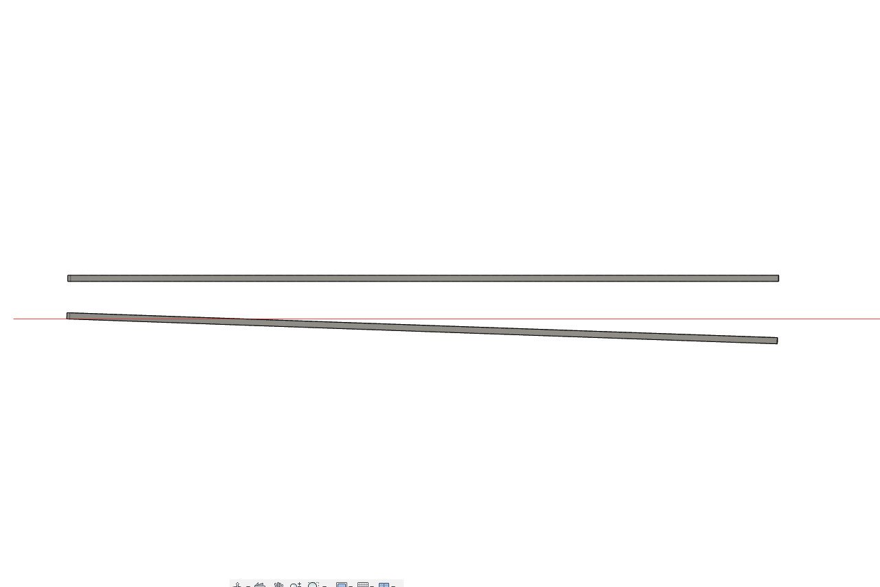
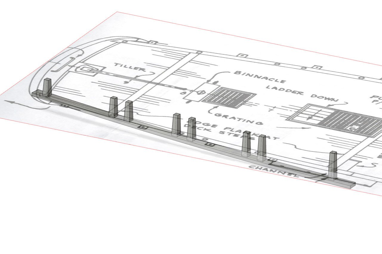
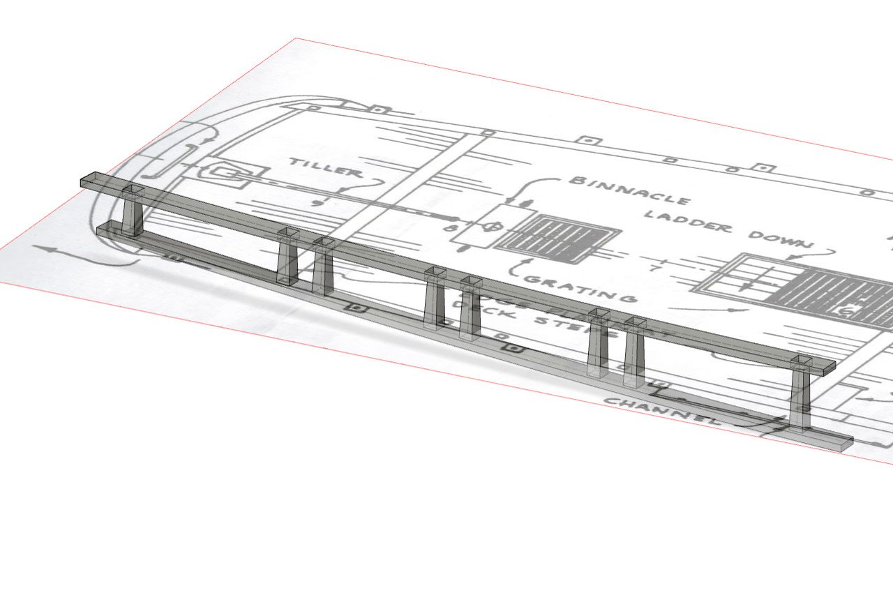
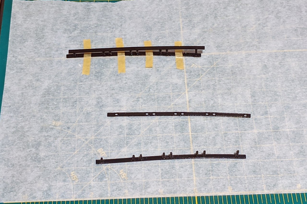
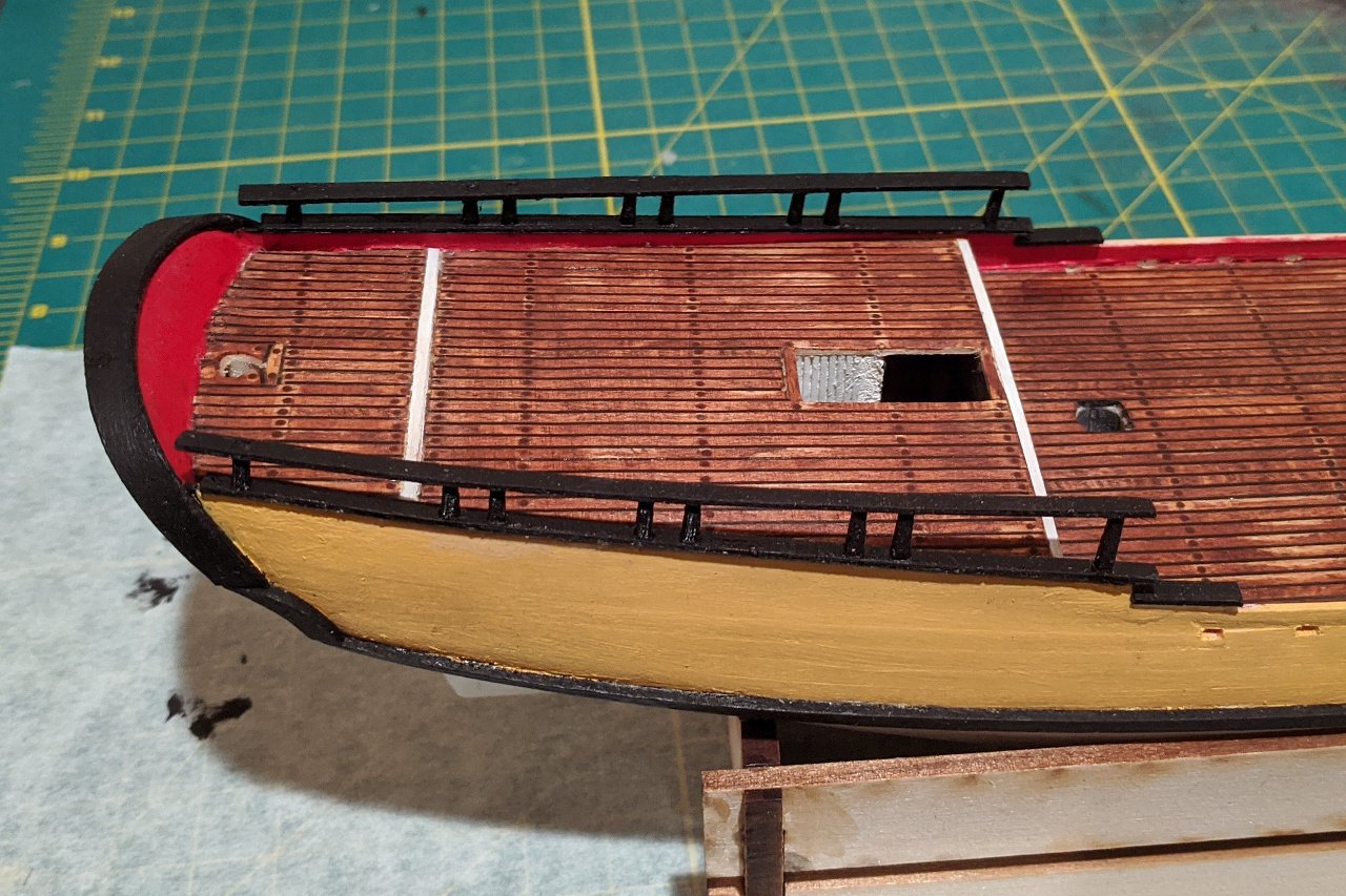
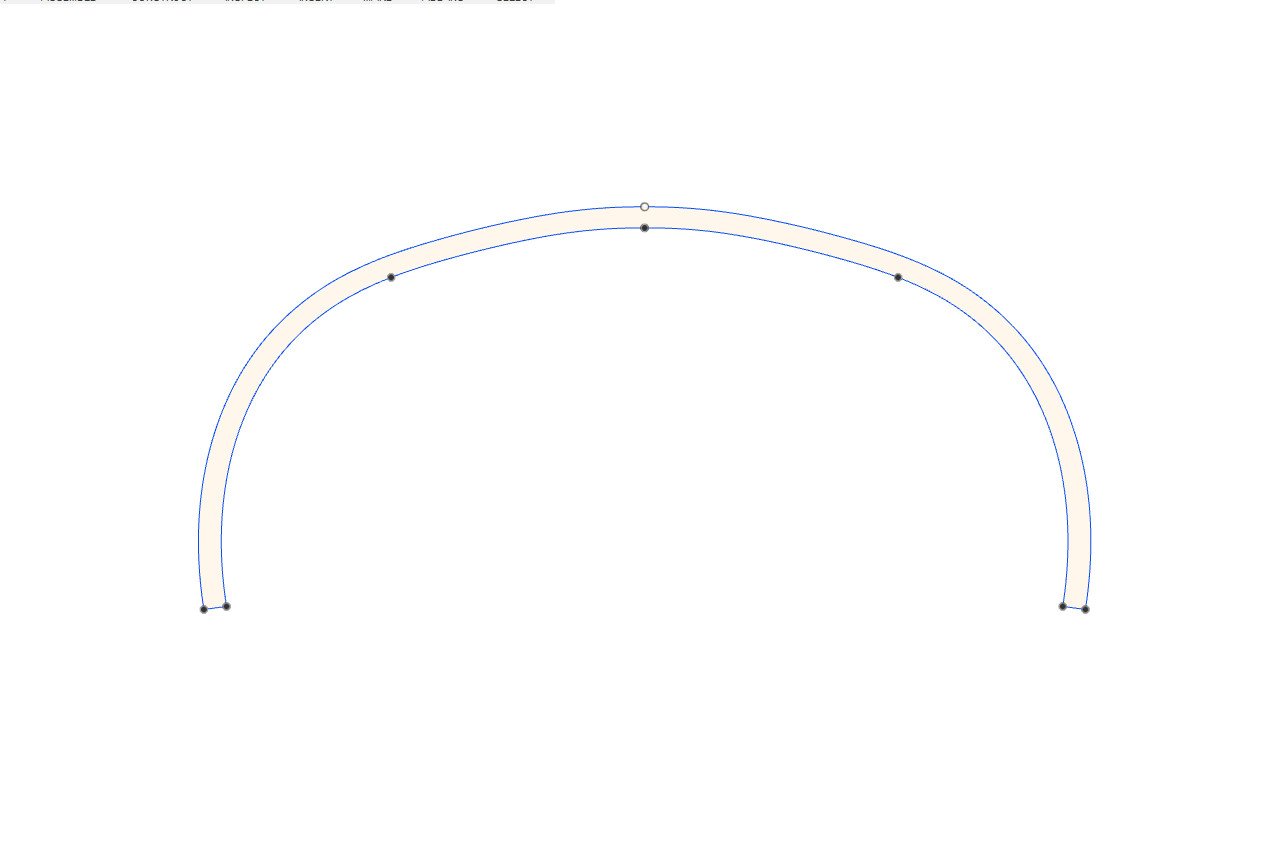
The aft rails are next. Below is a picture of the Sultana with the rail stanchions marked. Middle stanchions are in pairs, and there are singles at each end. (At least, that's what I assumed. The foremost may also be a pair, but I couldn't see it clearly in any pictures, and I went with a single.) I created the shape of the rail in Fusion 360 to match the curve of the edge of the deck. All rails here and in future steps will be 3.2mm wide and 1mm thick, to mimic 1/8" x 1/32" strip wood. I made a copy of the rail and positioned the rails in approximately the angle they would appear on the ship. The stanchions were added. Stanchions are 2mm square at the base, tapering to 1.5mm at the top. Stanchions are taller forward and shorter aft to match the angle between the rails. The upper rail was moved slightly aft, then square holes were added to accept the tops of the stanchions. Here are the 3D printed parts. The set above are being glued together. The set below are fresh out of the printer. And finally the rails were glued to the ship. The rails were painted with black to remove the glossy plastic finish. I also made some short rails for the next step down. These are also visible in the picture.
- 222 replies
-
- 6
-
-
- sultana
- model shipways
- (and 1 more)
-
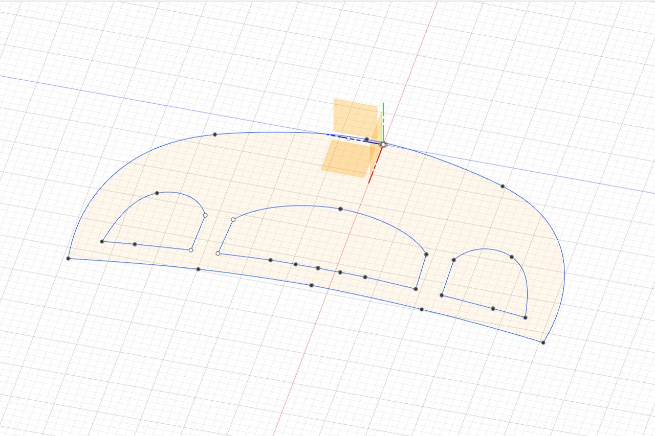
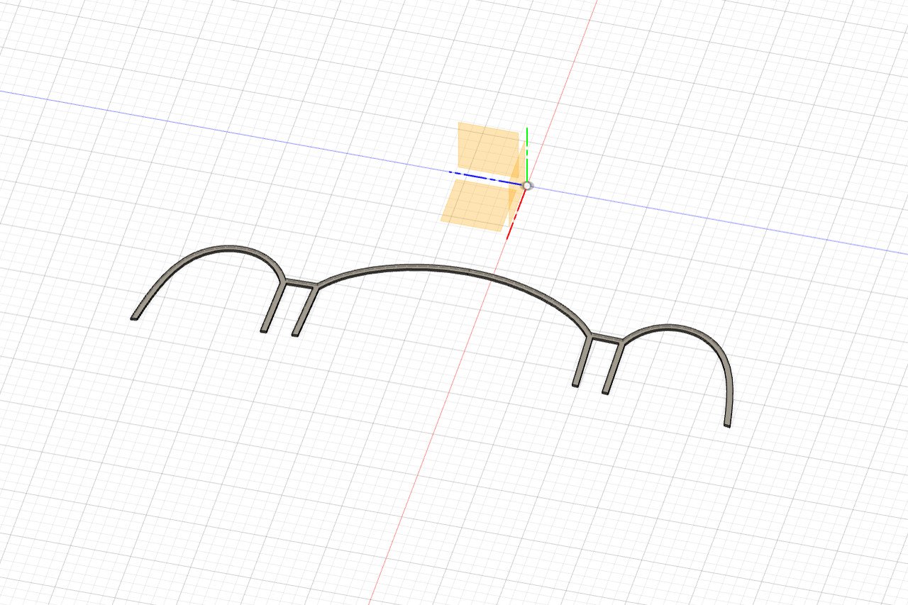
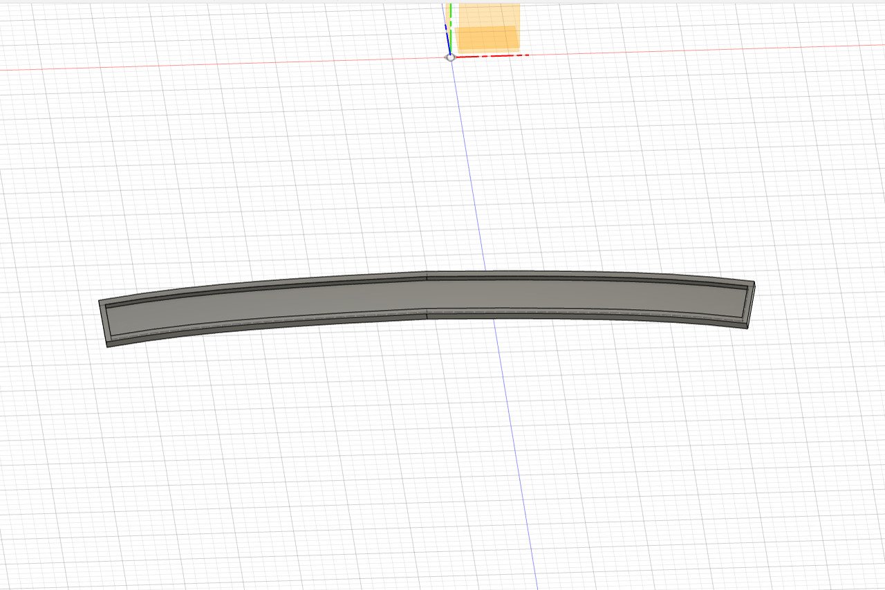
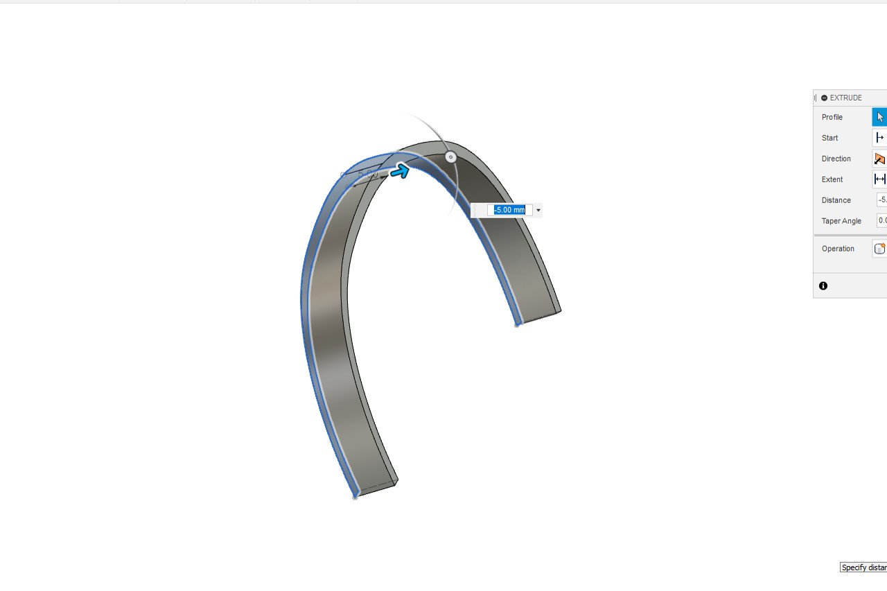
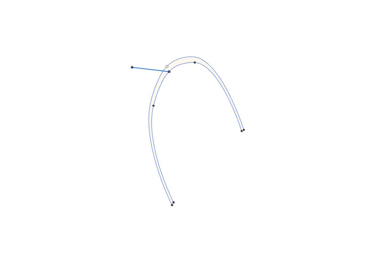
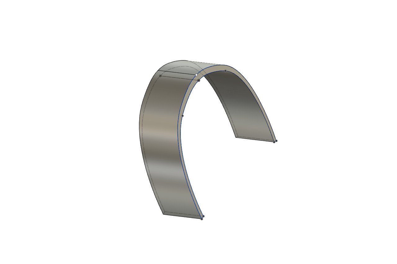
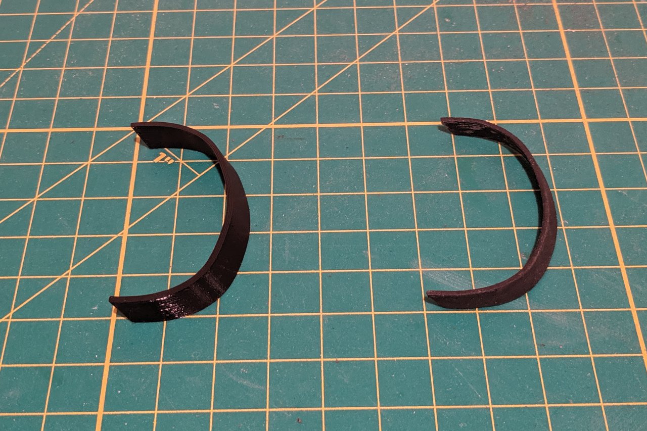
With the warm months just a memory, I'm back to working on the Sultana. There are several parts that I'm anxious about on this model. The cap rail over the transom is one. I tried to bend a wood strip for the part, but had little success. So I have tried to produce it via 3D print instead. Modeling it in Fusion 360 was also a challenge, and I ended up with something of a compromise, as can be seen below. I started with the curve of the transom shape that I had developed previously for the laser cut transom pieces. I thickened the curve to a thickness of 1.5mm. Then I wanted to extrude it horizontally. But when I tried to extrude I realized that it could only be extruded normal to the plane of the sketch. That wasn't what I wanted. It turns out that the Sweep, rather than the Extrude, operation was the correct one. I added a line in the direction and length (10mm) that I wanted. With that, the Sweep operation created the shape. Below on the left is a picture of the piece as it came out of my 3D printer. I intentionally created a piece longer than necessary, with the intention of filing it down to the correct fit. In the picture at the right is the final piece after being filed down. And the piece was finally glued into place. I created the small curved fashion pieces in wood, painted black, which merge the cap rail and wales.
- 222 replies
-
- 6
-
-
- sultana
- model shipways
- (and 1 more)