


hamilton
-
Posts
1,771 -
Joined
-
Last visited
Content Type
Profiles
Forums
Gallery
Events
Posts posted by hamilton
-
-
Hi Harlequin:
I'm not so sure....I don't mind the ratlines so much - throw on a few podcasts and settle in for some clove hitches....though on this one I think there will be more ratlines than I've ever done....I did close to 1000 on the San Francisco, but I think there might be a few more than that here.....chip away, chip away
hamilton
-
Hi Augie:
Yes, indeed - it's beginning to feel like I've spent forever on the framework - and there's a lot more to go! My one worry about the POF ship's boat is that its shape might not be exactly right for the type of boat it's supposed to be (a pinnace). I might find myself modifying it, as well!!
hamilton
-
Well I've finally finished shimming the outboard bulkheads...phew! What a lot of tedious work! I'll post some pictures later. Next comes some more niggling, but also I think more interesting work - framing the sweeps & ballast ports. Here's how I'll approach it.
1. Identify the waterline and mark it along the outside edges of the bulkheads
2. Mark a point on each bulkhead a little less than mid-way between the false lower deck and the main deck defining a line that runs parallel to the waterline (this is the location of the sweep ports, which run parallel to the waterline)
3. Install 2mm x 2mm scrap wood along that line to mark the lower edge of the sweep ports/ballast ports
4. install another set of scrap wood strips 2mm above the first set - this is the top edge of the sweeps
5. install a pair of scrap wood strips 5mm above the first set of strips at a point corresponding to and below gunport 6 - this is the ballast port
6. add small pieces of scrap wood vertically between the two horizontal strips to mark out the sweep ports which should be 2mm square
7. add small pieces of scrap wood vertically to define the ballast ports (5mm x 4mm).
Once this is done, I'll fix up the tops of the bulkheads and install the main deck. Then it's time for some serious fairing!! Good night to all
hamilton
-
Hi there:
So in looking through Goodwin's Anatomy of the Ship HMS Blandford, I've found a couple of clues (in different places) as to how to mount the ship's boat. Goodwin has an illustration on page 63 which shows the main sheet bitts fitted with a gallows. This resolves the aft mounting. Then on page 27, in the section with the photographic plates, there is a picture of a model from the NMM of a 20-gun 6th rate which is fitted with a gallows just forward of the fore hatch. Good thing I read the caption!
hamilton
-
I'm with Augie on this - in the past I've often given up updating my build log when it comes to the rigging simply because I can't seem to get decent shots! I'll have to try this technique - it's looking great.
By the way - I notice that you've got black standing rigging, though Corel only supplies hemp line....did you dye their line or did you replace it? If you replaced it, what did you use? I ended up ordering some of the usual Model Expo rigging line - not the best looking but easy to work with...I think that when I build the Bellona I'll order Morope to replace Corel's line - though I do like the Corel rigging line......
Anyway, looks like you're almost there! Looking great!
hamilton
-
Hi B.E.:
Thanks for the comment! Yes, this kit does beg for a good bashing. So far it's felt like most of the bashing has been my head against the wall! But with Goodwin's Anatomy of the Ship Blandford as a guide, I'm going to try to modify this kit quite a bit - as mentioned before, adding open bulwarks, adding sweep ports and sweeps, adjusting the belfry and f'csl rail, adding ladders to the f'csl, adjusting the rigging and belaying arrangement, etc.
One thing that's been plaguing me is how to mount the ship's boat (which I'm also replacing with a 3.5" plank-on-frame boat from ME). Corel shows the boat mounted aft on a gallows bit and fwd on the base of the belfry, which is centred on the f'csl rail. But Goodwin shows the belfry off centre, which means that the forward positioning suggested by Corel is not going to work for me.
Goodwin's book provided the solution - he shows the main sheet bits (which are not really included in Corel's kit at all but replaced by the gallows) fitted with a gallows up top. And then in the section of photographs, there is an example of an early model of a 20-gun 6th rate that has a gallows fitted forward (just in front of the forward hatch). So I'll be adding this as well....
Anyway, that's all for the future. After I finish shimming, the real bashing will begin - I'll frame out the sweep ports (2mm x 2mm - which will be quite tricky) and the 2 ballast ports (5mm x 4mm), fair the whole thing, and then start the first planking & building up the open bulwarks and re-doing the gunport frames....yikes! What have I got myself into!
hamilton
-
Hi Augie:
Thanks for stopping by! Yes there will be a lot of fairing to do - you probably noticed that the shimming on bulkheads 9 & 10 appears in the photo to be a little dippy...in reality it's not as bad as it looks on camera - it's just the angle. However, I've been rough fairing the bulkheads at the same time as I'm shimming so that I can try to get as accurate a run of planks as possible. The real fairing will begin after I install the deck, which needs some minor adjustments to the outboard edge in order for the planks to run smoothly. This is undoubtedly the most extended and tedious framework assembly I've yet done on a kit - though I imagine there are worse cases out there....
hamilton
-
Hi there:
Still mired in shimming the outboard bulkheads....2 nights in the last week and probably 2 more to go.....sheesh! I prefer ratlines!
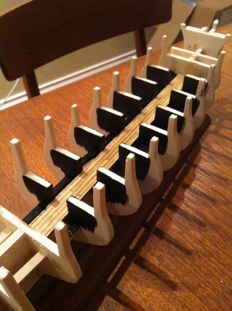
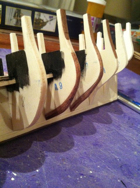
Anyway, I thought I'd post a couple of pictures to show the work in progress. I did take a bit of a break from shimming to plank & install the lower deck and blacken the bulwarks & bulkhead braces so they'll disappear when the main deck is installed. I imagine that not much is going to be seen of the lower deck once all is said and done, but I thought I'd plank it anyway with a 3-butt shift (no trunnels here, though I will take a stab at trunnelling the main deck).
As I mentioned before I'm using .6mm thick sapelia for the shims (courtesy of Artesania Latina). In the photos below you can get a sense of how much shimming was required overall across the port side (I've only just begun the starboard side), and also the thickness of the shimming at bulkheads 9 and 10, which were the ones that rode so high above the bearding line....

Anyway, once this is done, it will be on to much more interesting and fun stages of the build - installing the main deck, fairing the frames, installing the stern framing...
After this, I'm a bit undecided as to what to do next...the instructions would have me completing the framework by adding the cabin bulkhead and the quarterdeck and forecastle subdecks (before planking the main deck...but I don't think I'm going to do this....Instead, I think I'll do the planking (at least the first planking and inboard bulwarks), then plank the deck, then install both the cabin bulkhead (which I'll scratch build) as well as half bulkheads under the forecastle (as featured in Goodwin's Blandford book). Only then will I install the quarterdeck and forecastle.
I've also decided to scrap the gunport frames supplied by Corel and simply cut out the ports from the bulwarks...this is because I want to replicate the open bulwarks that Goodwin shows for the Blandford and which wouldn't work with the metal gunport frames that came with the kit.....I'm also thinking of going with a lighter wood for the outboard bulwark planking - something like boxwood or perhaps simply basswood finished with a nice light walnut or oak stain...Anyway, this is now getting ahead of myself - I suppose I shouldn't treat this log as a diary....
Stay tuned, more to come once this boring business of bulkhead shimming's done...
hamilton
-
Hi Harlequin:
I'm excited to see the degree to which you've triumphed over this kit! It gives me hope for the future. The rigging looks great and the build is really coming alive! It is a beautiful ship once she's all dressed up....following with an envious eye to the future....
hamilton
-
Well, Harlequin - at least I have something to look forward to....
I spent the first of probably 3 evenings shimming the outboard bulkheads on Greyhound. Using a test plank running up and down the bulkheads I've determined that, apart from the 2 forward bulkheads (2 & 3) that fall significantly short of the bearding line and the 2 aft bulkheads that do the same (8 & 9), I have to add shims at some point on 4 bulkheads on the port side and 5 starboard....lots of dull work ahead - though the future results will hopefully be much improved as a result of the plodding....
I'm doing the shimming in .6mm sapelia that I have left over in quantity from my San Francisco build of this time last year. The good thing about this, is that I'll be able to show in high contrast the amount of shimming I had to do. But if you'r making me wait for pictures of the Bellona, then you'll have to wait, too, for what will probably be much less impressive shots of my shimmed-up bulkheads....until next time - to all a good night
hamilton
-
Amazing work on this restoration
hamilton
-
Harlequin! When I saw the notification in my email, I rushed here expecting to be treated to some glorious photos of the assembled framework! And now I see it's left still to my imagination....which at this time in the afternoon does not work very well.....especially when I've skipped lunch!
Anyway, it's great to hear that you've started and I patiently await some eye candy on this forum. Bye for now and thanks for all your help with Greyhound!
hamilton
-
Hello Augie:
Phew!! This has probably been one of the more entertaining reads I've had in a while in all respects - and the build is beautiful. A real inspiration. Now that I'm caught up, it'll be much easier to follow along - even though I'm a bit of a late comer to the party. Keep up the great work!
hamilton
-
The busy life of the sports dad! I imagine it in my future, too - though most likely hockey.....not looking forward to the smell, but we must make sacrifices for our children, right? I will patiently wait for the Bellona log to start steam rolling along. Bye for now
hamilton
-
Just checked out NMM on their 20-gun ship models. There's one that features a ship's boat, from a later period, but the deck elements on the models of ships of the early 18th century seem to have gallows bits atop the main sheet bits and another gallows bits atop the fore jeers bits...so the timbers on both main sheet and fore jeers bits extend upward and are capped atop with a cross bar.
There seems something clumsy to me about this solution....especially since it tucks away the sheet and jeers bits in a kind of inconvenient way....if anyone has any solution to this issue, I'd be happy to hear it - thanks!
hamilton
-
-
Hi Dave:
Thanks for the tip - very much appreciated! I'll head over to the NMM site now
hamilton
-
Hi there:
I'm working on the Corel Greyhound, but using Goodwin's Anatomy of the Ship HMS Blandford as my guide. Goodwin's book is great, but using it has raised a point of confusion for me.
Corel's kit design has the ship's boat (a pinnace) mounted on spars that are placed foreward on little brackets on either side of the belfry, and aft on a gallows bit just before the main mast.
Goodwin's book has a different belfry design (the belfry is positioned slightly to port) and there are no gallows bits, but sheet bits before the mast...
Goodwin's book seems to trump Corel's instructions/design at many points, but he also gives no indication of how to mount the ship's boat....does anyone have any idea how this might have been done on a 20-Gun frigate of 1720? Any and all suggestions welcome. Thanks a lot in advance.
hamilton
-
-
Hi Blue Ensign:
Thanks for the tips! Yes, I agree that the double-black wale with the filling strake looks really nice. At this point, I would like to try to emulate the finishing of the ship that appears on Goodwin's cover (though I may have to subcontract for the decorative scrolls and such).
My 4-year-old son was trying to convince me to carve the lion's-head figurehead....but the last thing I carved ended up looking something like a bean, so I don't think that's in my future.
The crowsfeet scare me a bit at this scale, but I will give the a shot and see how it goes...Can you tell me if they're considered standing or running rigging...? Black or hemp?
Anyway thanks for reading!
hamilton
-
Hello Harlequin:
Thanks for the encouragement. The Goodwin book on the Blandford has been a real breath of fresh air I have to say. I think it will be fun to try to incorporate some of the details he shows on the Blandford - in fact, it's possible that this build might turn into the Blandford in the long run....
One photo in Blandford's book shows a model of a 20-gun frigate with the sweeps run out. I find the look of this so captivating that if I can get up the courage I may actually take the time to carve 36 sweeps at 1:100 scale to add this other bit of interest to the model....
Anyway, my limited life experience has shown me that what happens in the world of ideas so often stays there, so who knows....Anyway - what's up with that Bellona! My patience is wearing thin for an update!
hamilton
-
As if the last post wasn't enough - I'll also update a bit of progress - I spent last night prepping the centre keel
1. carving out the gammoning hole
2. Drilling a bobstay hole
3. Marking and carving the rabbet joint
4. Cutting out the seat for the figurehead from the knee of the head
After leafing through Goodwin and Lees, I'm going to add two more features this evening and then do some reading:
1. Drilling a second bobstay hole
2. Drilling a hole at the top of the stem for the main stay collar
That will be that - nothing really glamourous, but the books have made me a little more inspired for this build after the great disappointment I've been feeling given hurdles this kit presents...and I'm getting excited to make some modifications and bash this kit up a bit....bye for now
hamilton

-
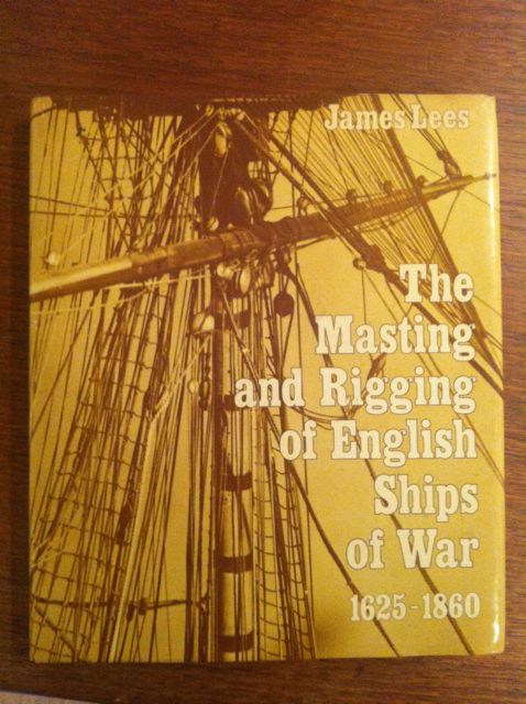
Well a bit more progress on the Greyhound to report....but first, I thought I'd show off a couple of new acquisitions

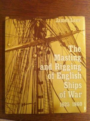
These both came in the mail today - and the timing couldn't be better - it's meant to rain all weekend, so how better to while away the hours....
I've leafed through both already and can see that the Lees in particular will continue to be an invaluable resource. The Goodwin book has been illuminating as well on a few specific points:
1. The open bulwarks at the waist, with the frame timbers used as stanchions for the rail - a feature I may use on this build
2. A series of oar sweeps following the waterline at the level of the lower deck - I'm thinking of finding a way to frame these out and add them using the system Chuck Passaro suggests for the sweeps on the Syren
3. An outboard hatch just beside the outboard ladders at the level of the lower deck - presumably for hauling supplies in and out - I think I'll try framing and adding this, too.
4. an anchor lining on the forward channel - also an easy add
5. The main wale features a thinner filling strake, though the diagram says "c. 1719" - the solid built wale is also dated "c. 1730" - so it's a little unclear whether the solid built wale corresponds to the 1719 Establishment, or whether the filling strake would still have been used....any ideas out there? I kind of like the look with the filling strake....
6. Crowsfeet on all three masts - which I'm not sure I can easily do at this scale, but which I'll try...
7. The belfry on the forecastle is towards the port side with one timberhead to the port side and three to starboard, allowing for ladders up to the forecastle port and starboard - I will definitely add these, as in the Corel plans, there is no indication of how the forecastle would have been accessible at all....
It's possible that if I want to stay as true as possible to the 1719 Establishment I'll have to add a solid wale and close off the bulwarks, but I'll need to do a bit more research on this - unless someone has a quick answer....
I've also noticed some discrepancies between Lees accounts of the 20-Gun ship of c. 1719 and the Goodwin text:
1. Lees lists 2 bobstays on a 20-Gun of 1719 - and while Goodwins drawings show two bobstay holes on the stem, he only puts one bobstay on...
2. Lees has guys p/s on the jibboom, with a running tackle eye-spliced to the spritsail yard, running through pendant blocks spliced to the end of the jibboom, back through blocks on the spritsail yard and held fast on bow timberheads
3. Lees belaying illustration for a 20-gun ship of 1719 has a very different deck arrangement than the Blandford/Greyhound. His illustration shows a vessel that clearly has a square beakhead bulkhead and a foremast on the forecastle, while the Blandford and the Greyhound have a rounded bow and the foremast on the main deck - though in other elements, the two books agree so some sense might be cobbled together from both
4. Goodwin has main sheet bitts as well as the main jeer bitts - something missed by Corel, but also represented differently by Lees. I think I'll follow Goodwin here.
5. Lees illustrates horses on the bowsprit that run through a stirrup spliced to the forestay and held fast to a bow timberhead with a deadeye-lanyard set-up. I had thought of adding footropes to the bowsprit, but since neither Lees nor Goodwin mentions these, perhaps there were none...I'm not entirely sure what function the horse played....any ideas?
Anyway - sorry for the long post! I guess I'm just excited to have these new resources to peruse....bye for now!
hamilton
-
Thanks for this detail Harlequin! This strategy makes a lot of sense. I'll be returning to this for sure when the time comes....
hamilton


HMS Blandford by hamilton - FINISHED - from Corel HMS Greyhound - 1:100
in - Kit build logs for subjects built from 1501 - 1750
Posted · Edited by hamilton
Hello all:
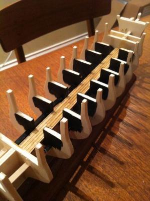
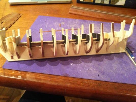
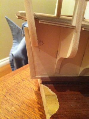
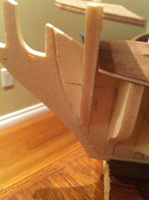
A quick update to show the beginning of the sweep port framing. I marked the waterline along the edge of each bulkhead. The sweep ports run parallel to the waterline, so I needed to establish that first. I then (stupidly) started installing the lower and upper frames along the waterline - WRONG! I should have measured up from the waterline the total width of the wales and then marked another set of lines there parallel to the waterline marks! Eventually I figured this out, undid about 2 hours worth of work and quickly did it again....made some small progress. Here's how it looked.
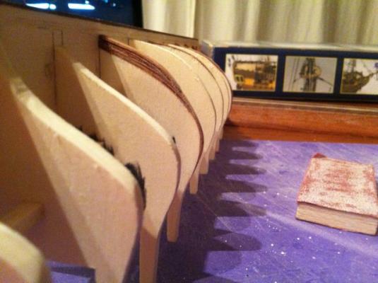
First, here are a couple of shots of the completed shimming.
Then, here are some of the frames installed wrong....
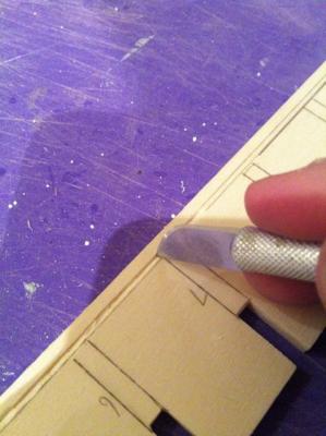
Here is a template I made to mark the bulkheads, so I could plot out the positioning of the sweep ports and the ballast ports.
The sweep ports are 2mm x 2mm and are spaced 12.5mm apart beginning just fwd of gunport 2 and continuing aft - a total of 18 on each side. The ballast port is 5mm wide x 4mm high and is situated below gunport 6 at mid-ships port and starboard. Here are a couple of close-ups of the template to show where the sweep ports and ballast ports are marked.
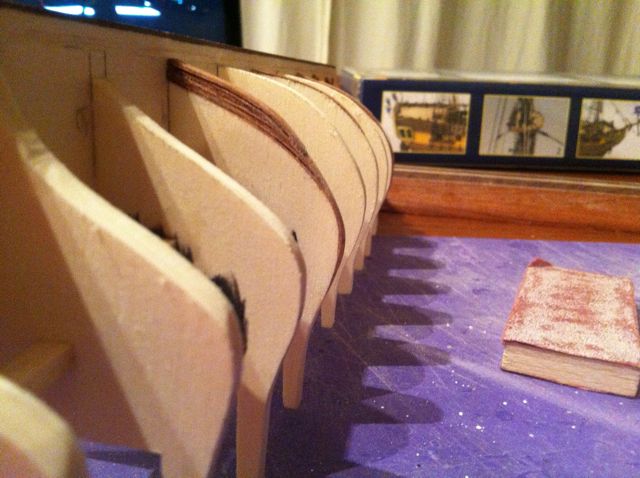
Now all these pictures feature the poorly positioned frames. Here is a final shot where the frames have been repositioned more correctly.
They still seem a shade too low, but it is honestly very difficult to try to visualise how things will look once everything is planked up....if they turn out to seem loike a disaster, I will forget about them and just plank over....Anyway, I'll post again when this process is complete. I've now completed all the lower frames on the port side and (as you see) a few of the upper ones. Still the rest of the upper frames and all the tiny little vertical frames to go and then repeat starboard....Bye for now
hamilton