


hamilton
-
Posts
1,933 -
Joined
-
Last visited
Content Type
Profiles
Forums
Gallery
Events
Posts posted by hamilton
-
-
-
Have to agree with Russ and Javelin - the planking is very impressive - after 15 models I still cannot achieve these results....clearly something is eluding me that is more intuitive for you Ronald - patience, perhaps! In any event, this build is a real treat to follow
hamilton
-
@Nirvana - Yes that's my scratch Bluenose (the last model I completed) in an early stage of development - you'll also recognise Syren perched between the frames of another project I've been slowly working up in secret - a 1:48 scratch of HMS Scarborough based on the Anatomy of the Ship Blandford - which I'm building using a hybrid P.o.B. (from the gun deck downwards) P.o.F. (gundeck and above) approach - it's another version of the 1:100 scale Corel Greyhound I built as Blandford over a decade ago.....work at the bench is slow, but time still flies!!! Aspects of Einstein's relativity theory can be experienced in this way!
hamilton
- Dave_E, robert952 and East Ender
-
 3
3
-
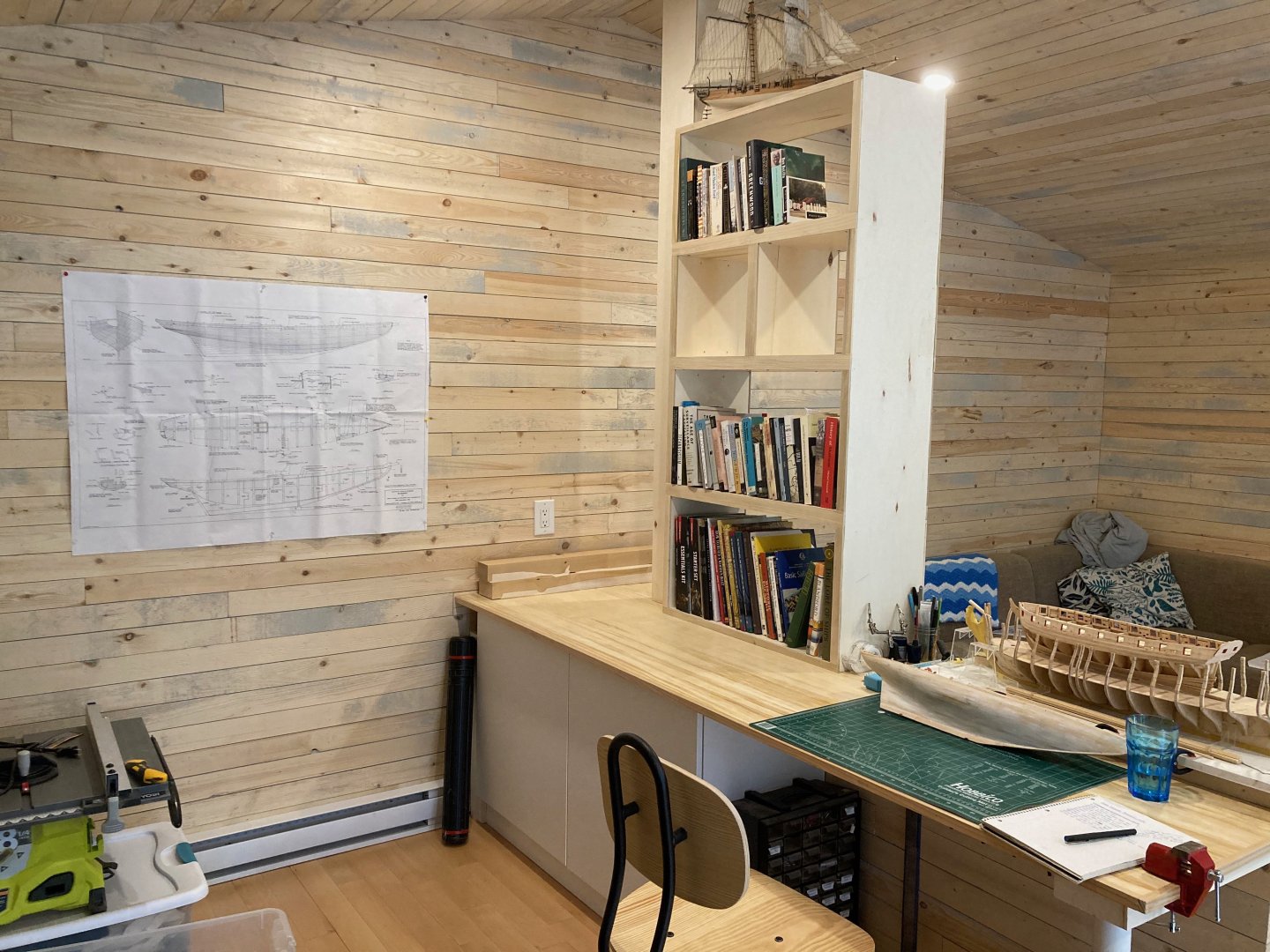
Hi Tim - nice looking space - I'm guessing you use that two-hander saw on the wall for particularly large modelling projects.
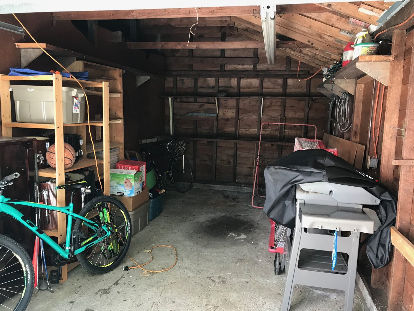
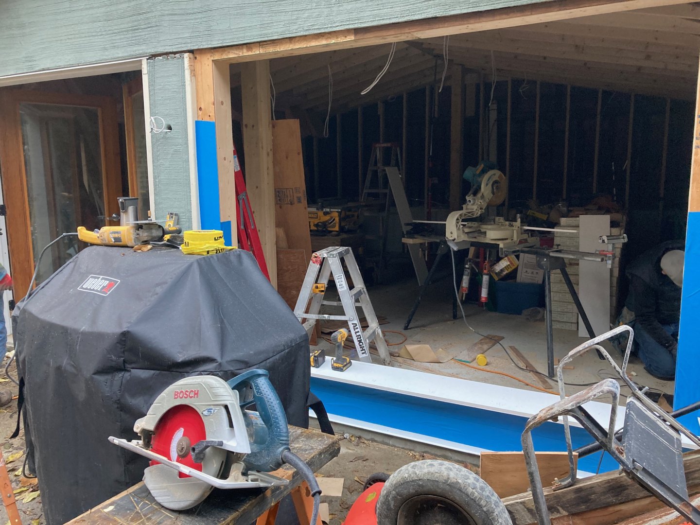
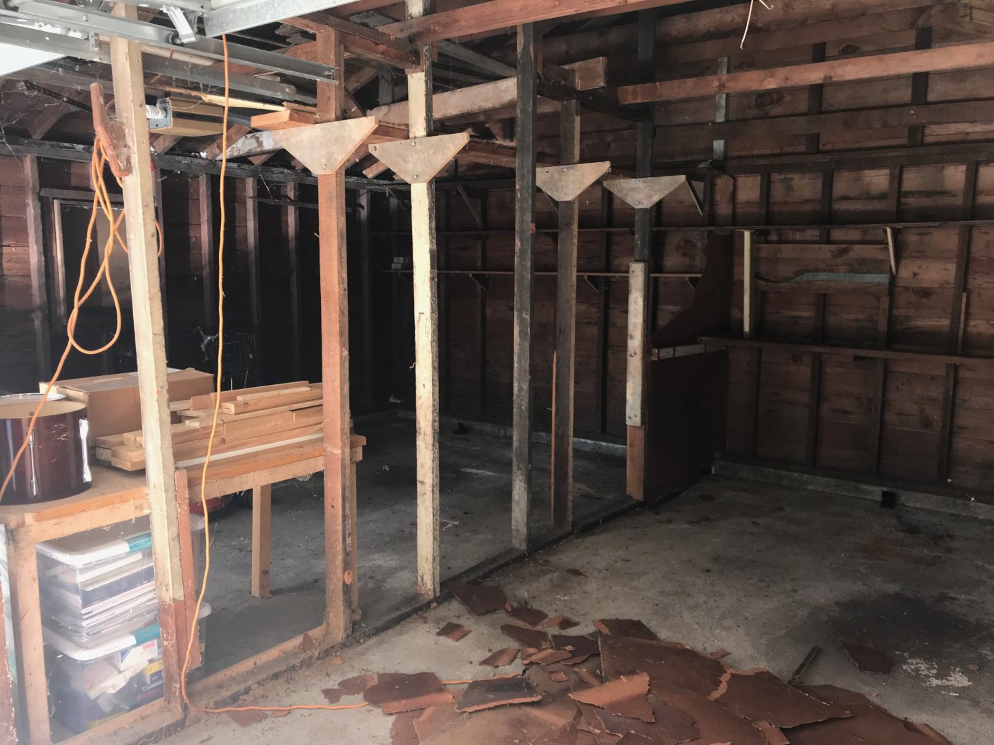
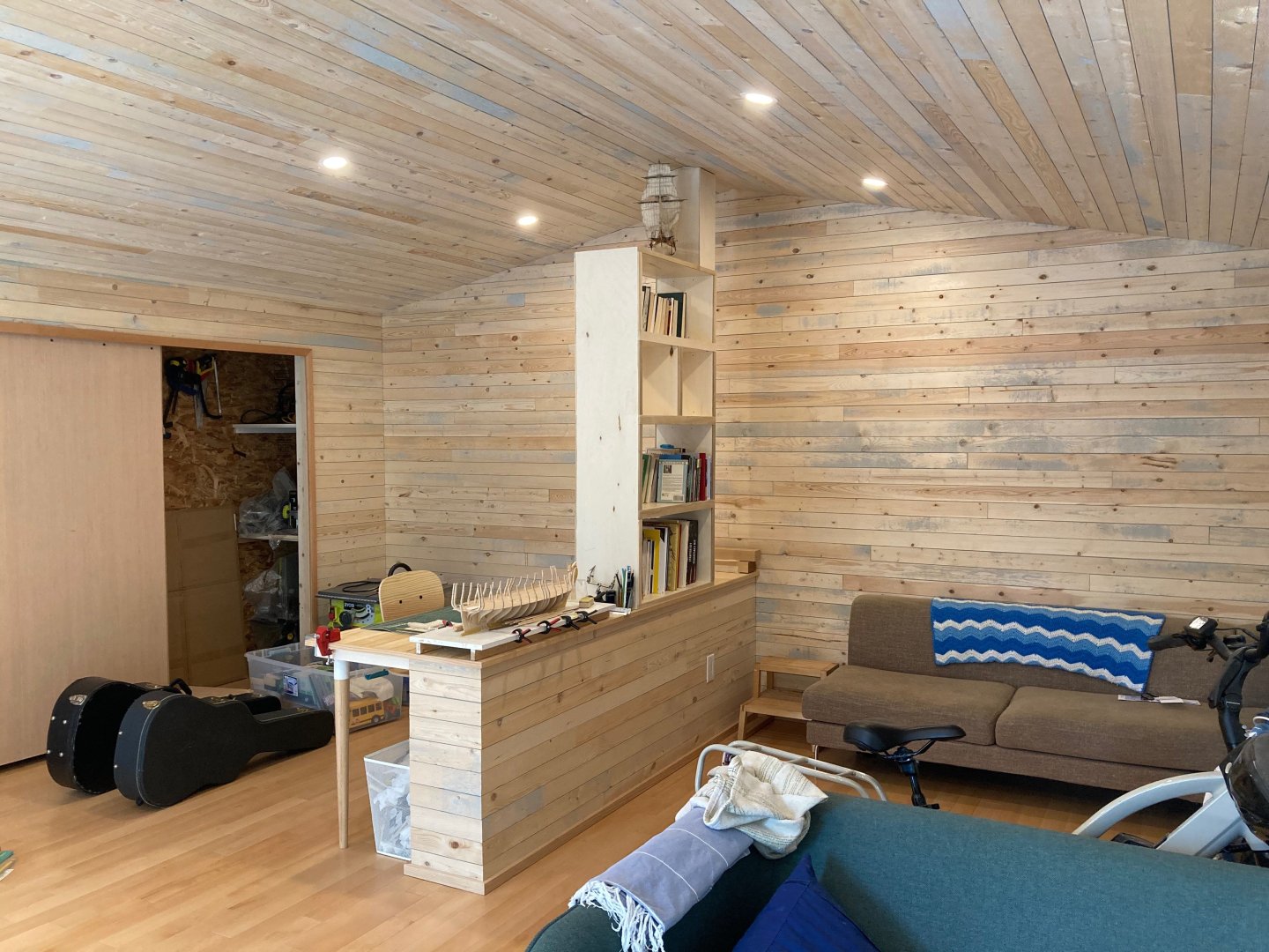
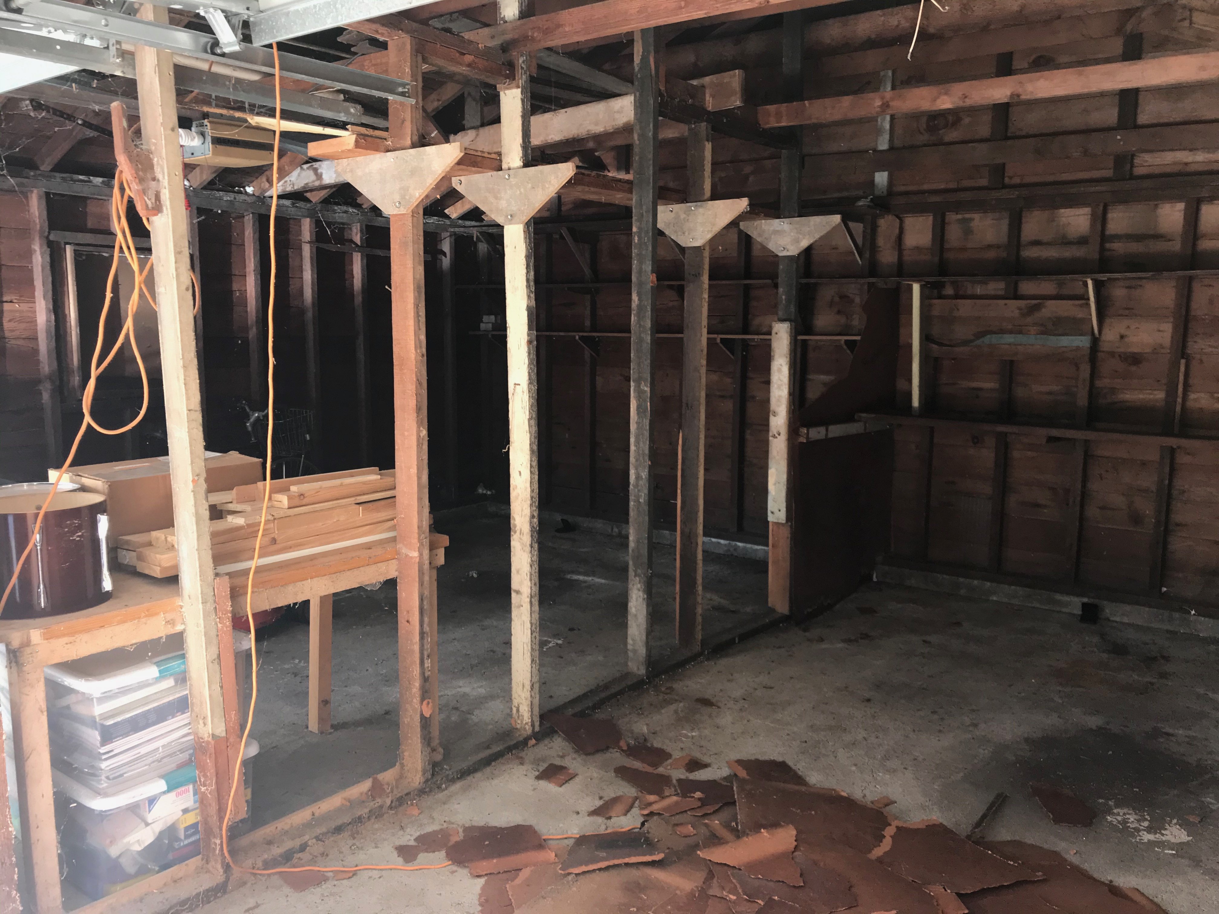
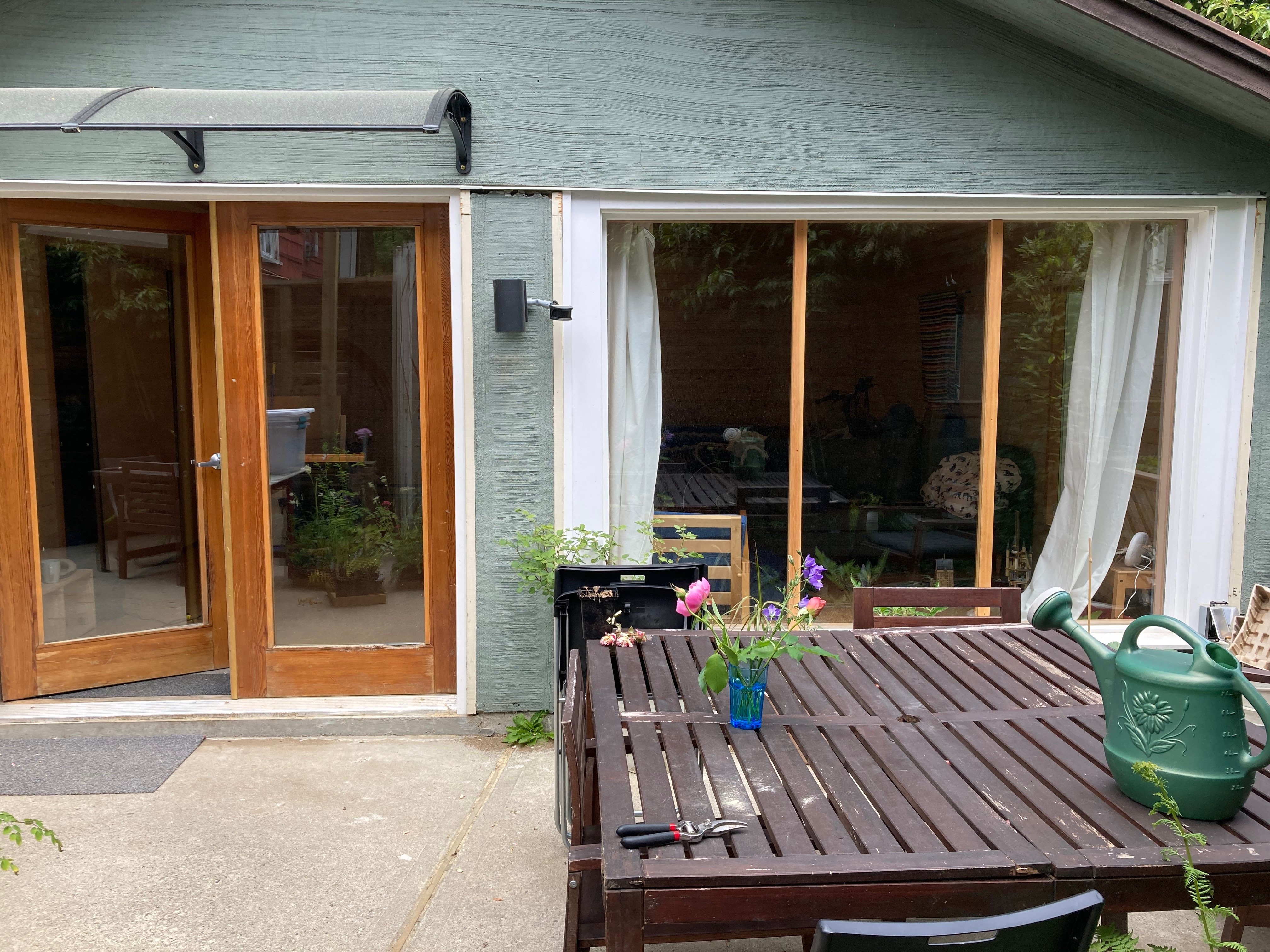
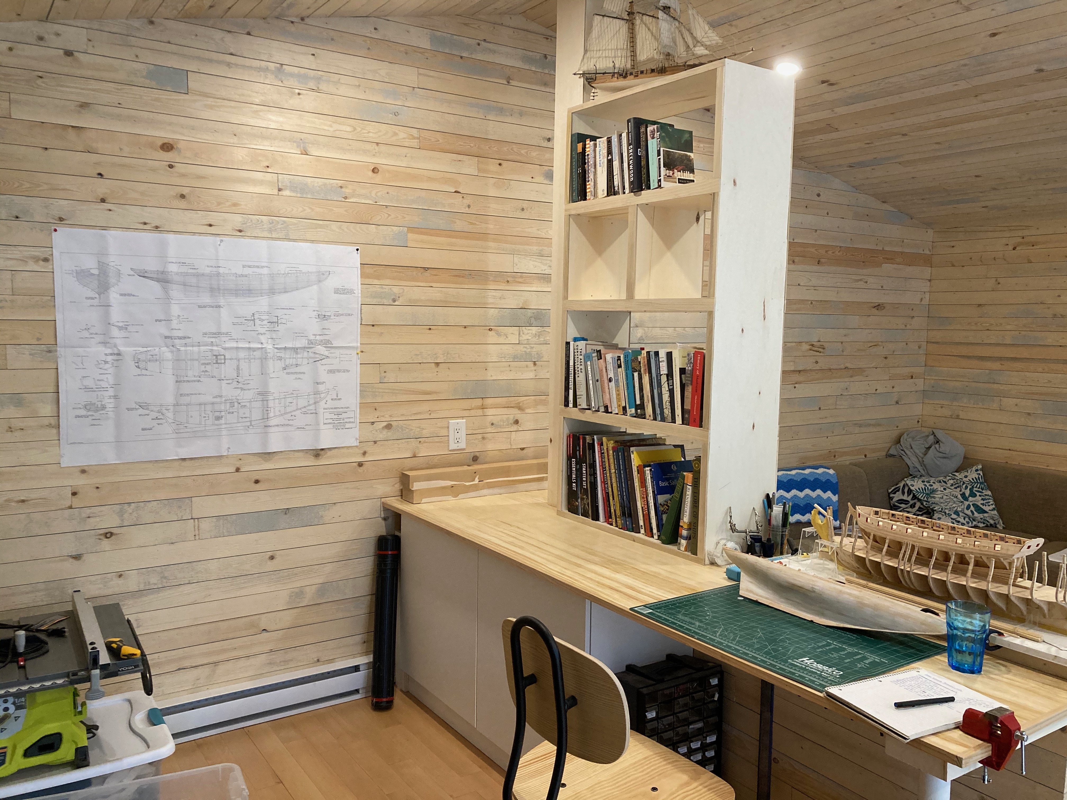
Here's my little corner of the world - though honestly it has not seen much use lately, sad to say - been too busy with work and home projects and other things for the last few months.....a couple of before shots of the dilapidated garage it used to be for comparison....the "after" photos were taken when it was more or less brand new (2021) - it is a bit messier now with more tools and more storage space....but it's a nice spot to be in on a sunny Saturday morning with a hot cup of coffee.
hamilton

-
It is hard to believe that a model manufacturer can long sustain the cost of absorbing the tariffs - though I also acknowledge my ignorance of the business side of model manufacturing...I just can't imagine that there is the kind of critical mass, given competition among manufacturers, for this to be a long-term solution. Fortunately for us Canadians, we can still import from Europe under CETA without these concerns and we (like US customers) are exempt from the UK's VAT as I understand, but our market is (like in everything else) tiny taters compared to the US....will be interesting to see what the future holds...regardless of how expensive it gets, hull planking still drives me crazy!!
hamilton
-
On 8/29/2025 at 5:51 PM, sheepsail said:
Otherwise China could simply ship to Canada or Mexico first.
Actually, in response to US tariffs on China, China imposed tariffs on Canada (I personally don't get that logic, but).....so them shipping through us is not a viable solution for the import tariff situation south of the 49th.....one thing seems clear - that things are just going to be more expensive unless you can source domestically - regardless of what country you live in....time to tighten your belts!
hamilton
- Paul Le Wol, Canute and Shotlocker
-
3
-
Cool idea - as an occasional puzzler (1 at Christmas, completed furiously; 2 in the summer, nibbled away at in my leisure) I've noticed that there are a diminishing number of good subjects and manufacturers seem mostly to be going for either branded images (disney, star wars, etc.) or really crazy-making and repetitive ones (near identical red and white striped candies in a bowl, or a bunch of watches in a pile, etc.). There is the Ravensburger 9000-piece Battle of Algiers (which I hope to get as a retirement gift - though my pension statement tells me that I won't really be able to afford to retire until my mid-70s), but right now that is not a realistic possibility, attractive as it is.
I usually try to find historical images, cityscapes or landscapes - but these are increasingly not on offer by the main manufacturers, and I just can't bring myself to do a puzzle featuring kittens playing with yarn or an assortment of Disney princesses (no judgement against those who go for that sort of thing). These images immediately attract the eye and are actually interesting subjects even for people who aren't into ship modelling.
hamilton
- Canute and thibaultron
-
2
-
Well it's been a while since I posted here - been in and out of town a lot, but mostly the issue is that I am completely stymied by the main deck framing.....I've got the beams cut and I made what I thought would be a useful framing jig, but now I really have no idea how to proceed....notching out the beams for the beam arms and carlings seems relatively straightforward, but fabricating the lodging knees and beam arms to account for the deck camber has my head spinning and every time I've sat at the bench, I find myself just looking at things, trying to decipher from the practicum exactly how to go forward....so at the moment I'm stuck and with work starting up again next week (!!!) I'm not sure when I will be able to just knuckle down and start in....
If anyone has any tips or pointers for this part of a fully framed model, I would deeply appreciate it....but this log may be silent for a bit until I can get my head around things and get back to work once again......
hamilton
- Knocklouder, Mike Y and CiscoH
-
3
-
Ahh the quartergalleries!!! This brings back memories! I think you absolutely made the right decision going your own way with these! the metal parts are both brutalistic (as a single cast piece) and also really finicky (if you wanted to paint them in anything approaching an aesthetically pleasing way). yours look good! A nice improvement on a flawed (but ultimately not too bad) kit.
hamilton
-
-
In BC we only pay GST and PST....12%. HST is in place in some provinces (Ontario, e.g.) as a slightly lower combination of these two other sales taxes....These costs are not my problem, though - for the cost of this particular kit, which is on the cheap side at $127 USD, I'll shoulder them. The issue is I can't even choose to this since I can't even make an order to Canada at all....Model Expo has taken my choice away....which I don't appreciate....
I do get why a US business would take this route in the current environment - in fact, I imagine it's tricky for many businesses to look too far into the future right now if they rely to some degree on foreign markets - but I think it should be left to the consumer to decide whether they are willing to shoulder the extra costs, rather than cut out a whole national market for a product that is already relatively low-demand....I'm certain that there are Canadian modellers (like myself) who would be willing to absorb the extra costs at least on lower-cost or medium-cost models (the current sale at M-E would still, even with duties and taxes, bring the cost lower or maybe about even with the non-sale price of the kit), rather than turn to what is undoubtedly an even more expensive source - British and European sellers and manufacturers....
Anyways, a high-barrier hobby just got a little less accessible - at least above the 49th parallel.....can't say I'm very happy about it.....good thing I have a decent back log of unstarted kits....at my current construction speed it'll probably be more than enough to ride out the current period of trade uncertainty!
hamilton
-
Hi all:
I had decided to purchase the 1:48 Phantom pilot boat from Model Shipways but discovered that Model Expo is no longer shipping to Canada because of tariffs.....this decision makes no sense since there is, as I understand, a de minimis exemption for shipments of under 800$....happy not to give ME my money if they're not willing to recognise these exemptions or make exceptions for those of us who may be willing to pay more regardless of the tariffs.....ship modelling is hard enough without politics getting in the way.....
hamilton
- MBerg and Knocklouder
-
2
-
The plating looks really fantastic - once it weathers up it'll be even better! Am now seriously considering this model to replace the 1:96 one that got destroyed...
hamilton
-
-
I can see how the coppering might have slowed you down a bit....not the most exciting, but still an exacting part of the build...before my 1:98 phantom got destroyed, the copper plates had begun to age quite nicely. I like the way this part of a model interacts with the climate over time - reminds you that the work is a living thing!
hamilton
-
It's good to hear that the kits will (in the future) still be available - I hope Chris will continue to make them available in chapters as yours so far have been....this makes them much more accessible to modellers on a more limited budget!
hamilton
- thibaultron, Ryland Craze, Chuck and 2 others
-
5
-
Thanks Druxey - I will make a couple of sanding jigs (concave and convex, using the deck beams as blanks to get the correct round-up. I have some 1/2" maple ply that I think I'll use for this purpose as it's mostly scrap anyway and will be firm enough to withstand some sustained kinetic action. Was thinking I'd sandwich a few pieces of this together to make a nice broad surface for the sanding of the beam arms. With the upper deck beams more or less completed and dry-fitting snugly, I think I can also proceed to a part of the build I'm looking forward to - making the bitt pins for the sheet and jeer bitts - the first bit of superstructural detail since I made the well...
In any event, at this point I probably won't be able to get back to Echo until mid-July, and then we're out of town again at the beginning of August....sheeesh - this summer is vanishing rapidly.....and it's not even summer!
hamilton
-
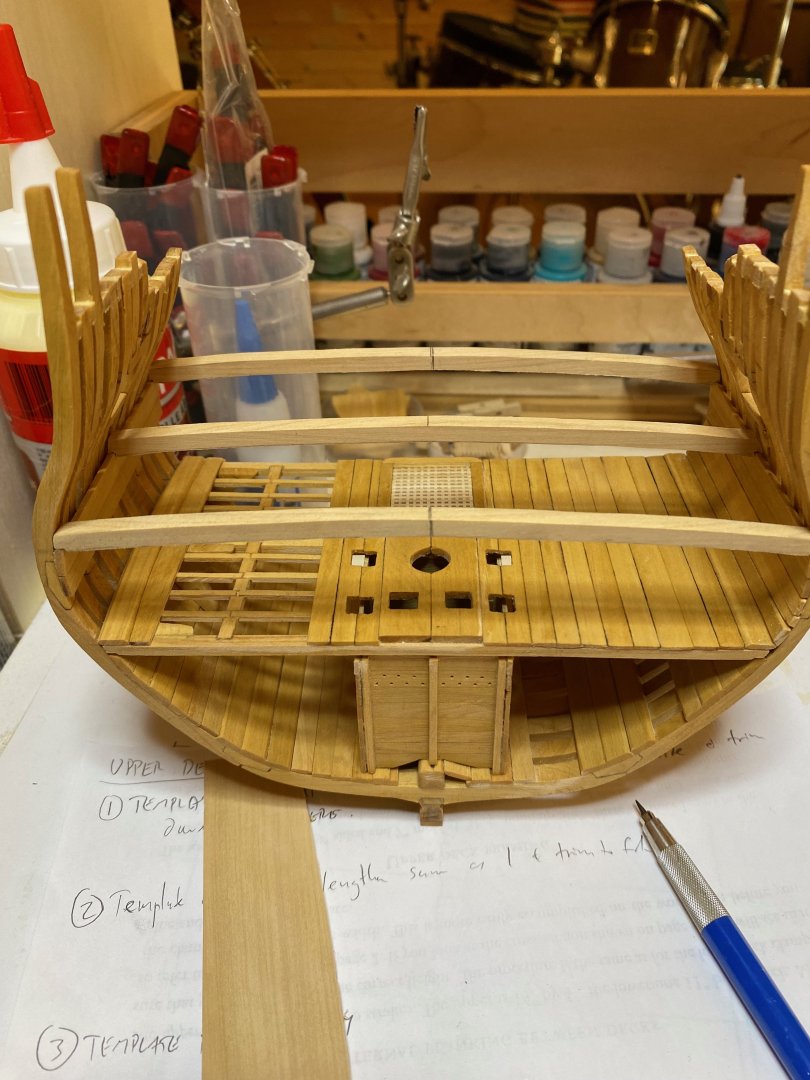
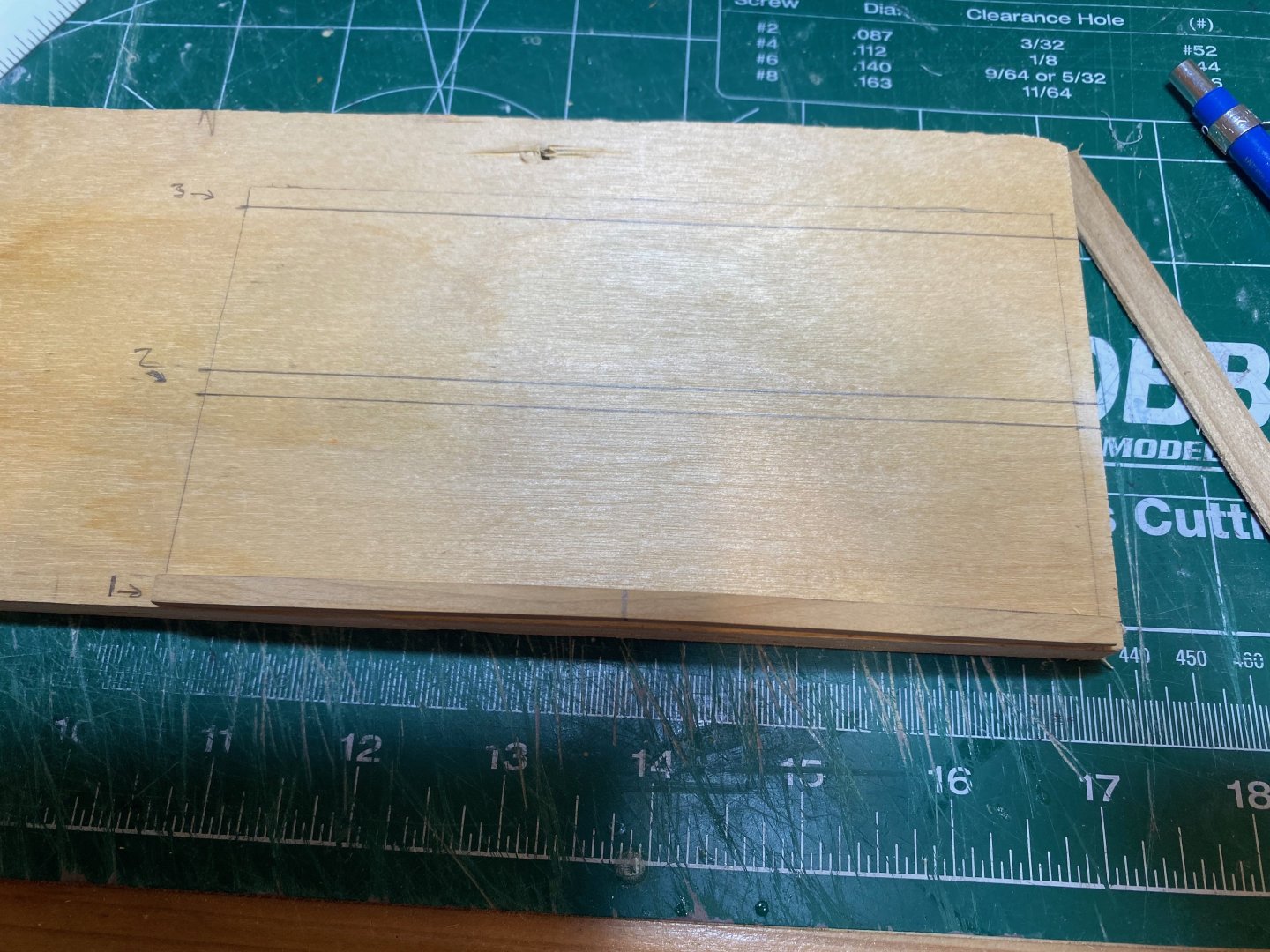
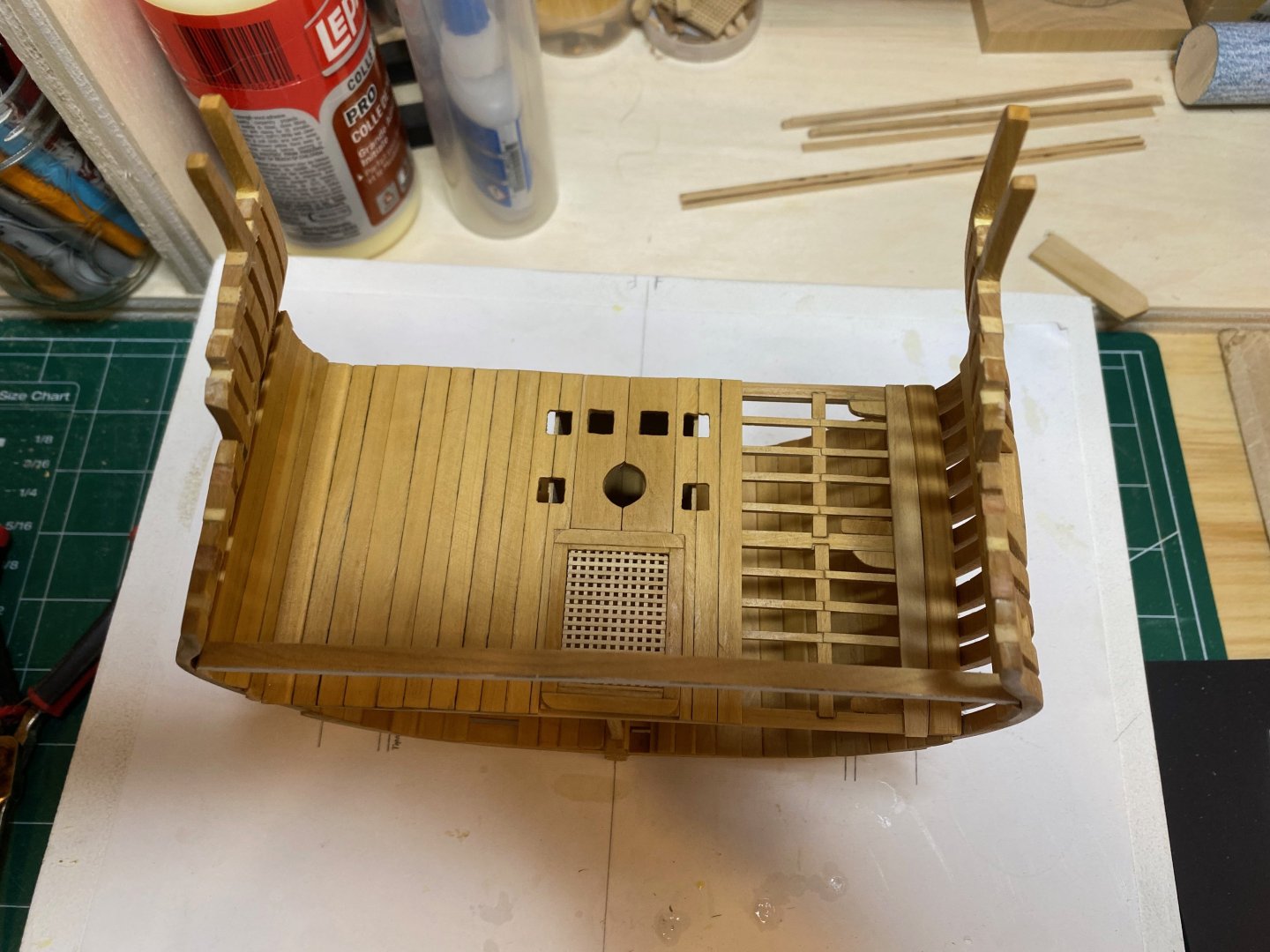
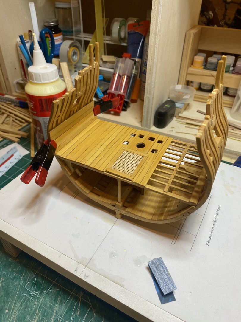
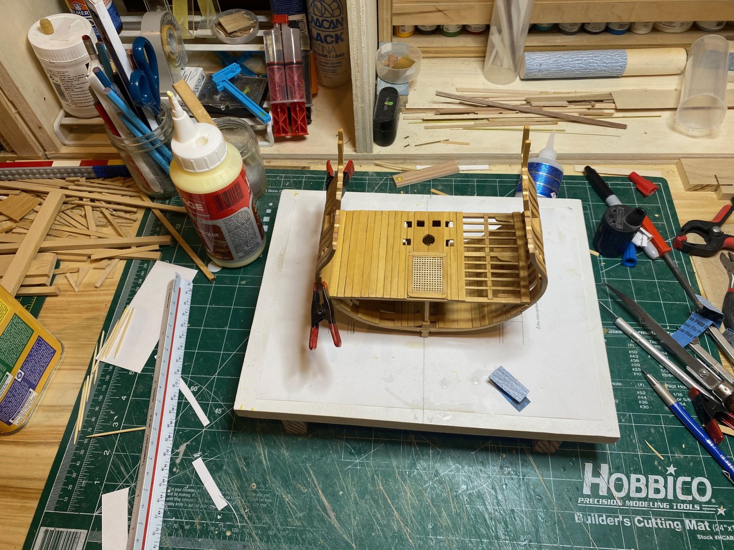
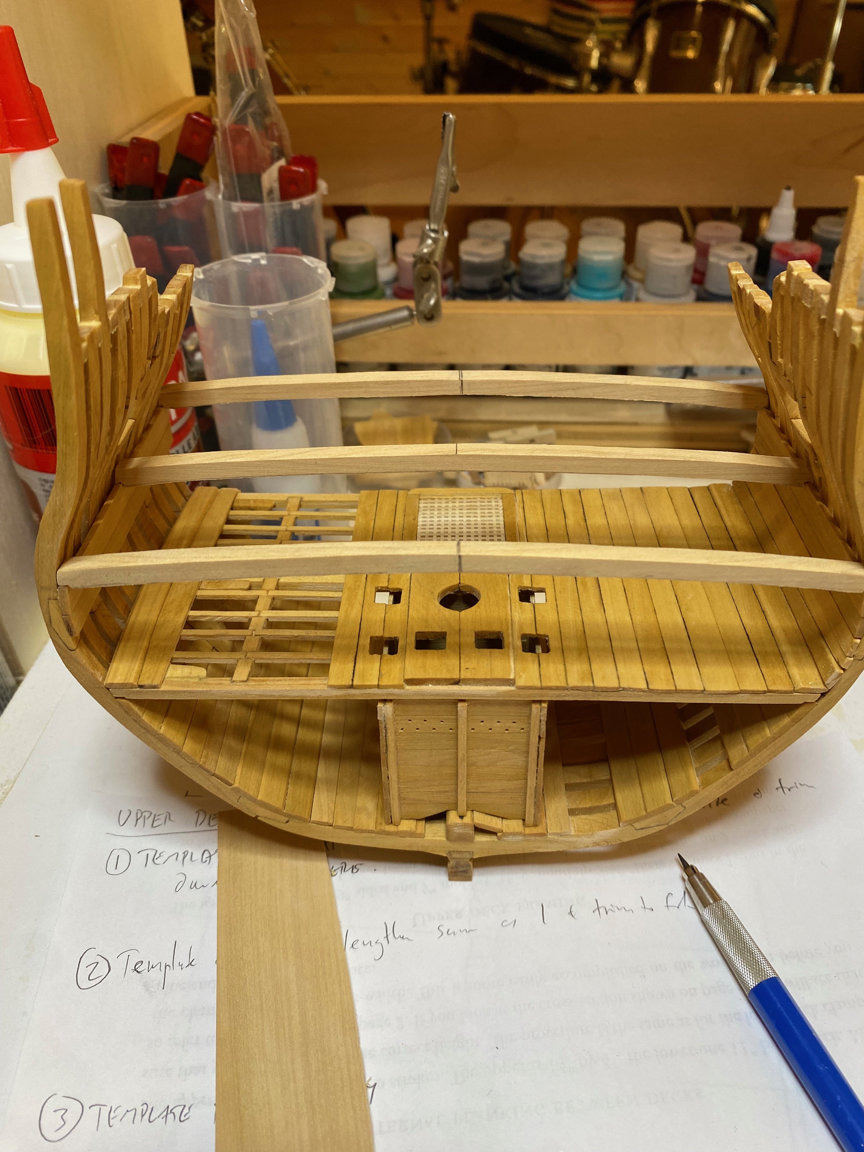
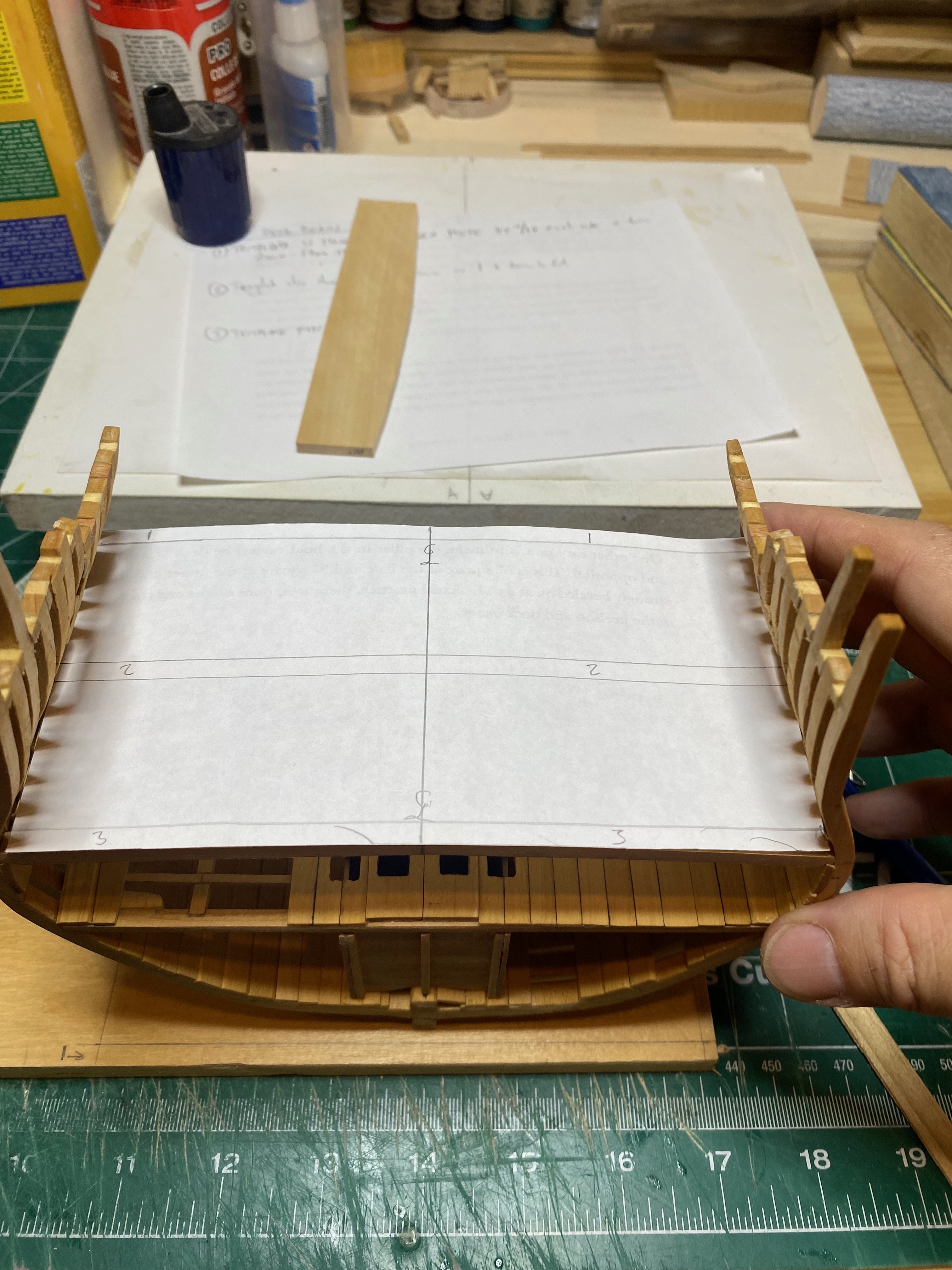
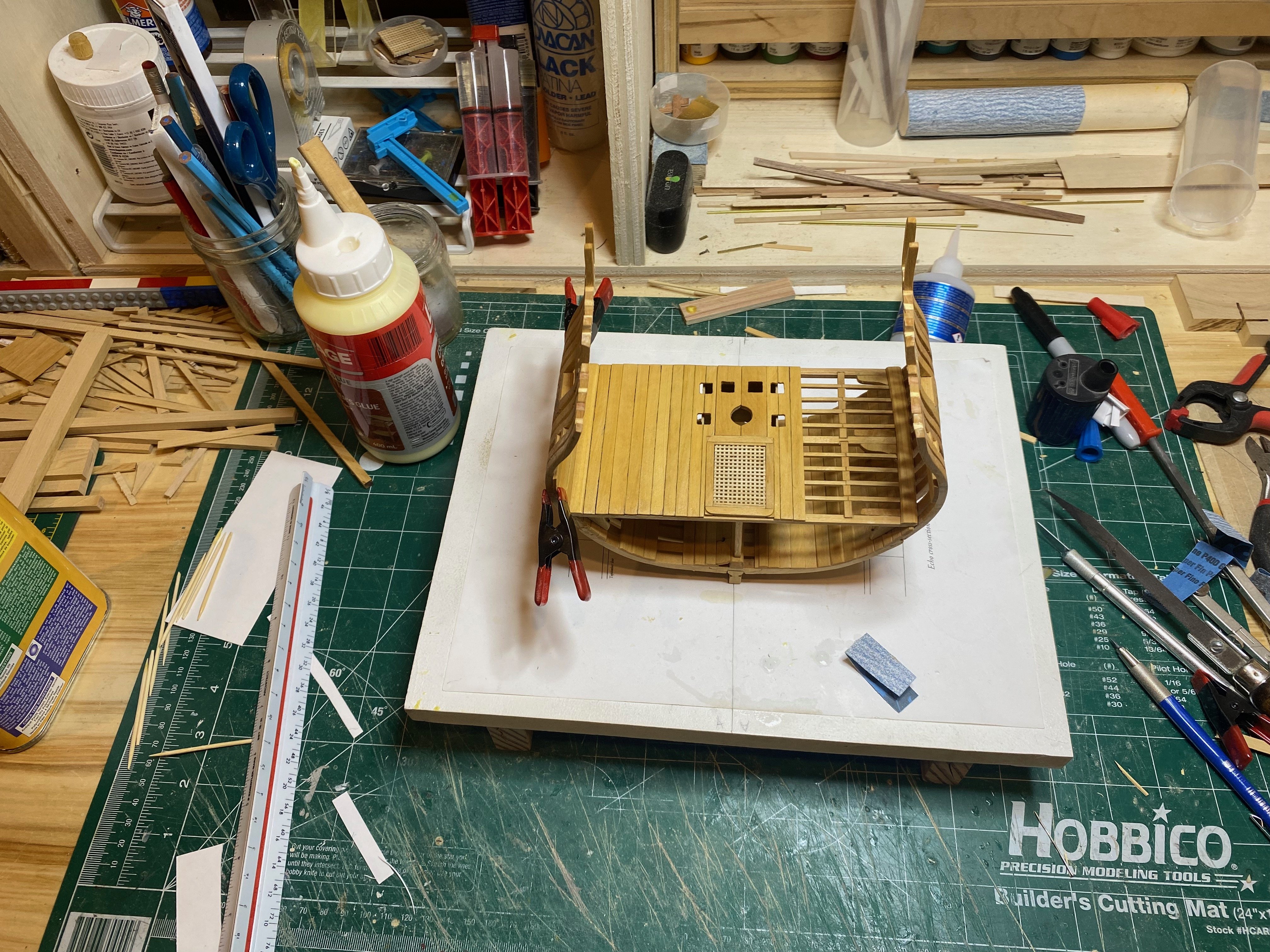
A bit more work on the upper deck framing. I've made all three of the deck beams and started to refine them (they're not quite finished but I'm not aiming for perfection, so....). My main task now is to make a framing jig so I can assemble at least the major components (beams, beam arms & carlings) off the model as I did with the lower deck. As of now I've gotten as far as making a template of the deck with the beams marked on. My model deviates slightly from the layout given in the practicum (modeller error is the blame here) so I'll use the drawings as reference for finishing the template.
I had thought of making a simple jig - fitting a couple of 1" (scale) thick battens along the port and starboard side to simulate the deck clamps (into which beams are let down 1") and then a 5-1/2" batten down the centre line (the deck rounds up by 5-1/2"). We'll see how this goes and whether I need to expand on this basic concept.....
I am a little concerned about the beam arms - these seem to be a little finicky to get right considering the round up needs to be sanded into them as well....I'm going to be away for a couple of weeks as of Friday and this week's a busy one getting ready to go, so it's hit or miss whether there'll be any time in the shop...but...in the meantime enjoy the photos and happy modelling.
hamilton


-
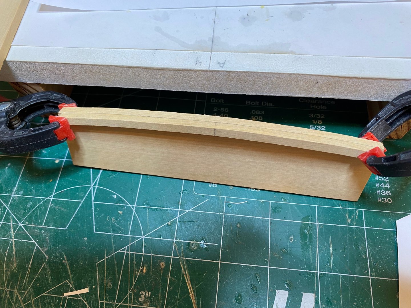
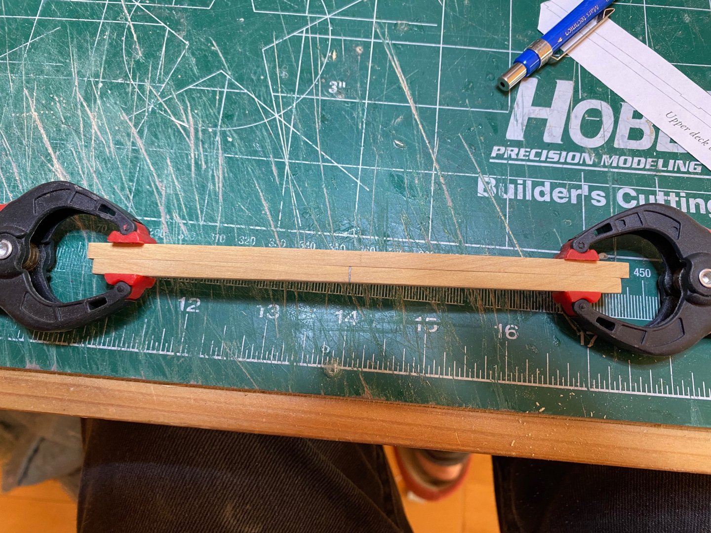
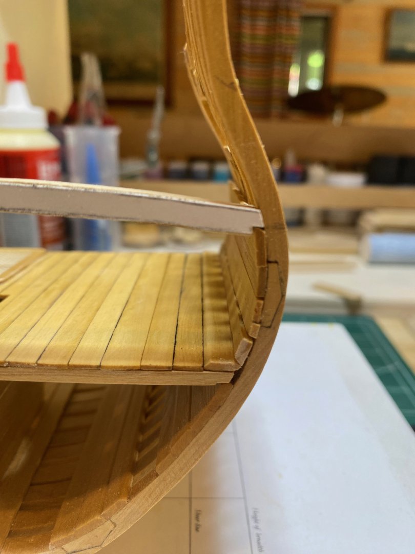
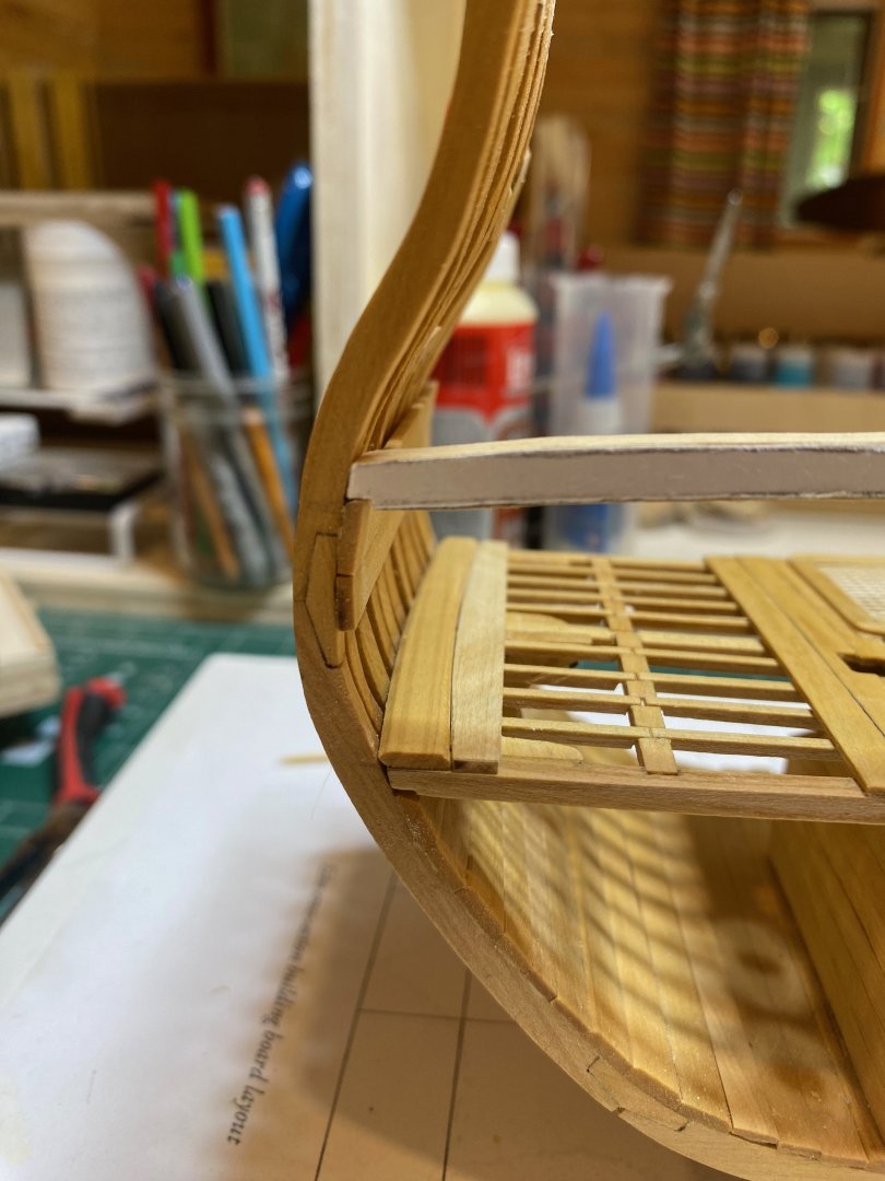
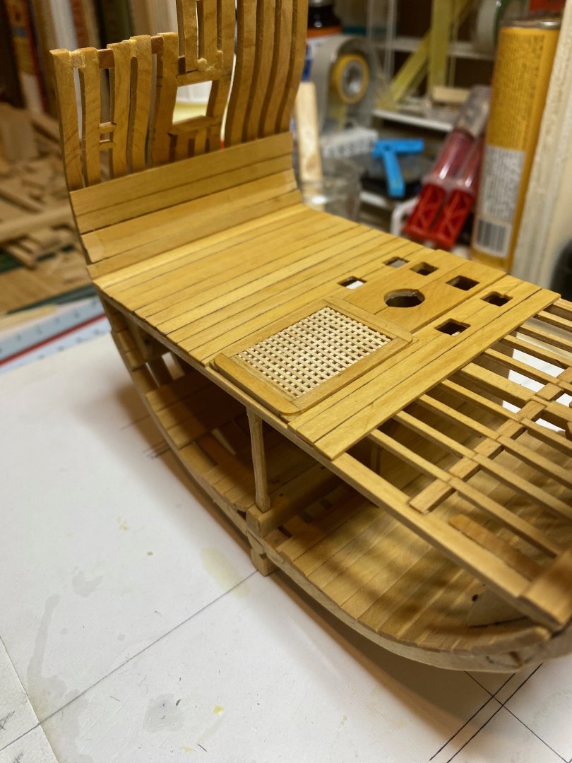
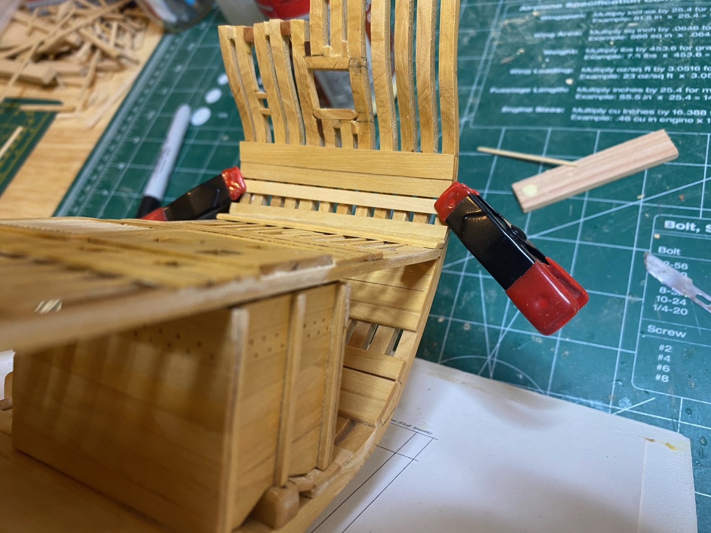
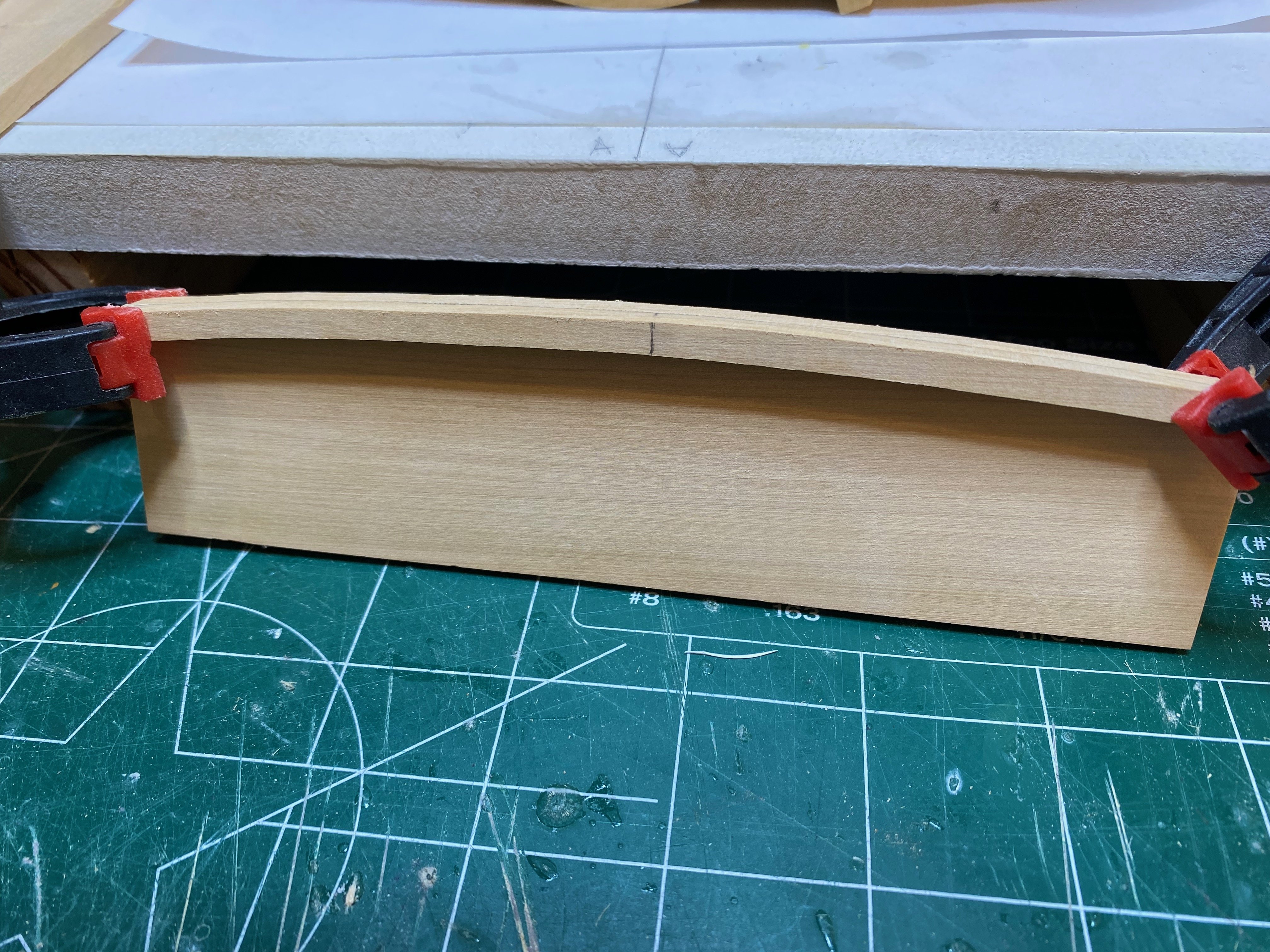
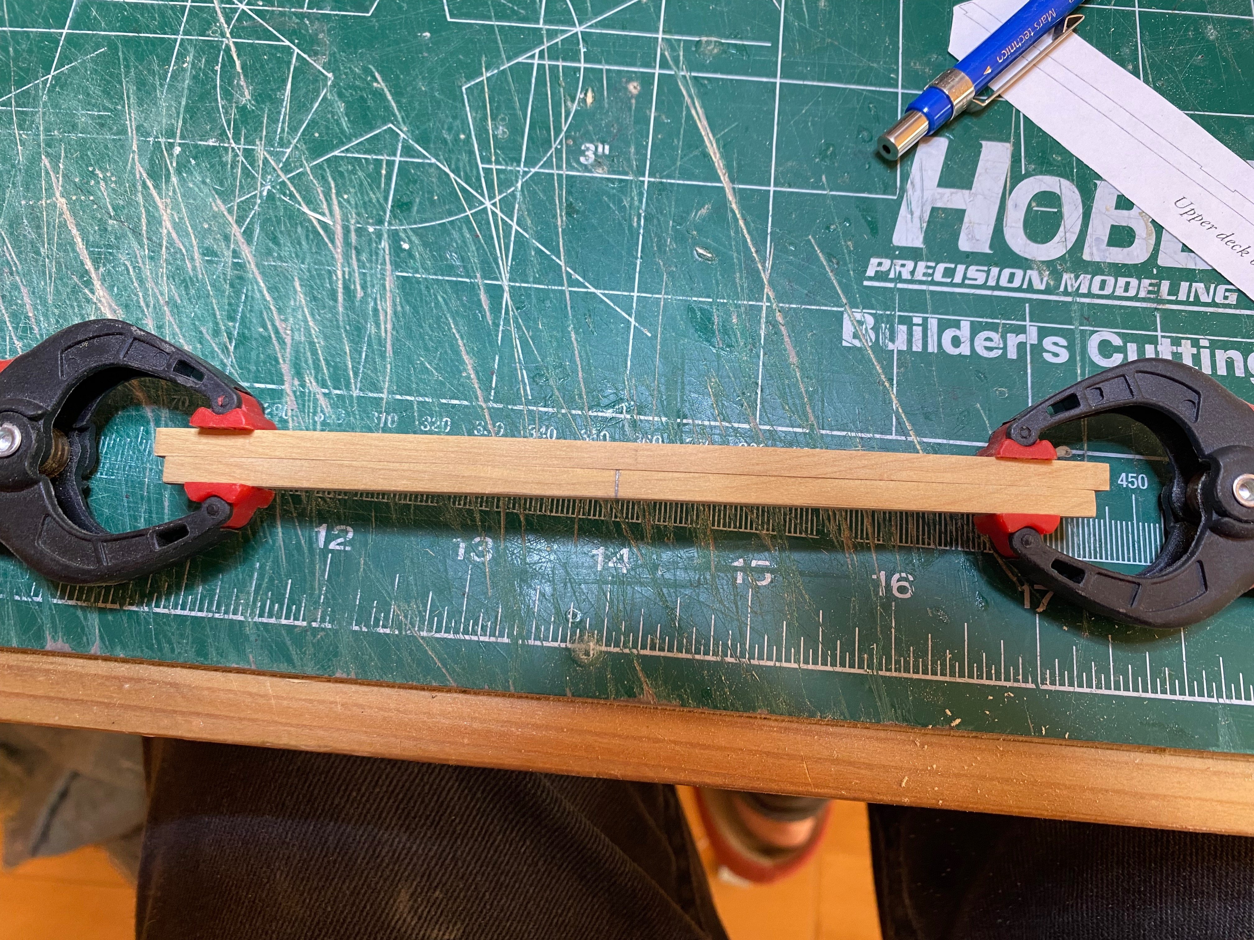
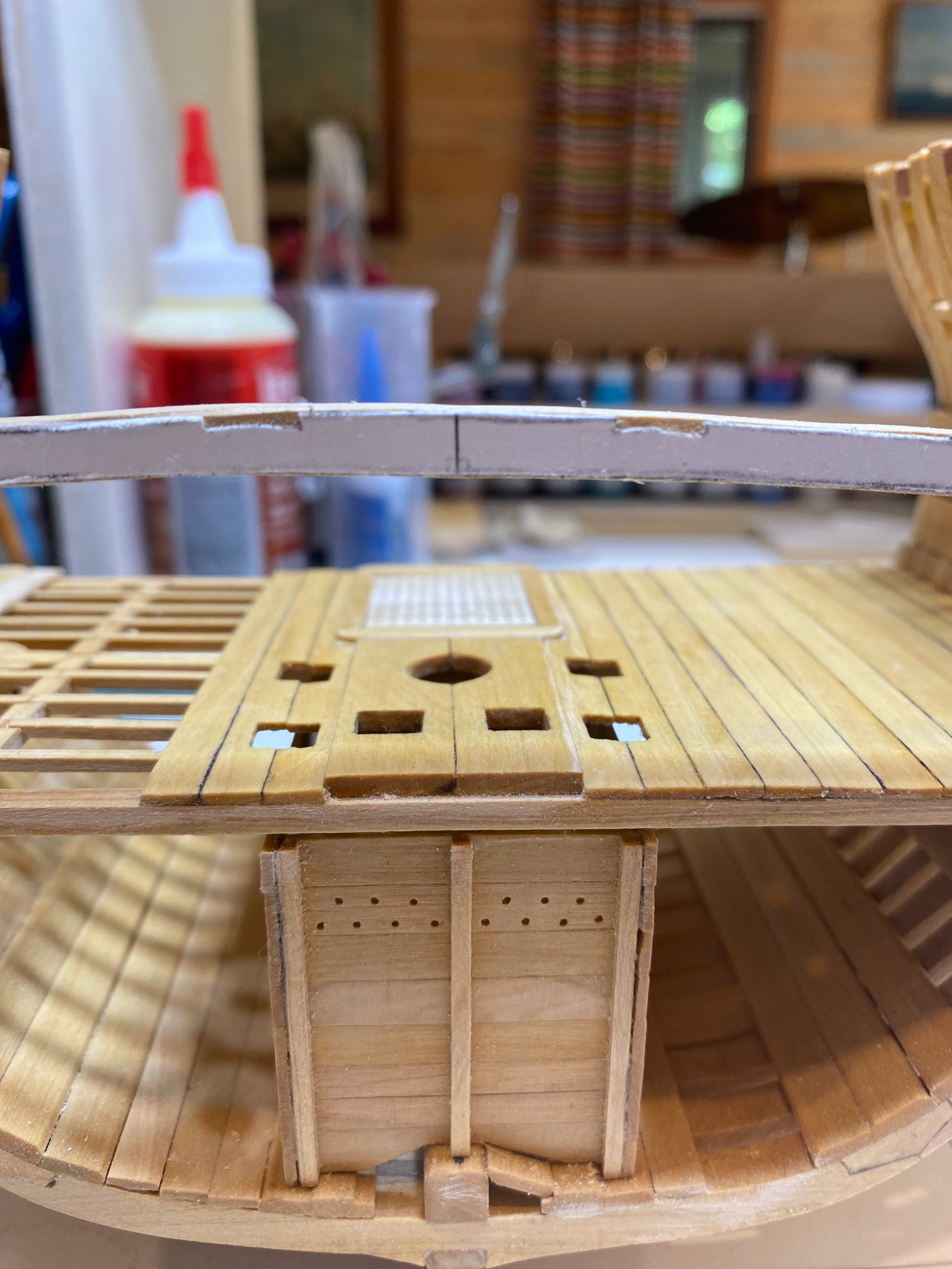
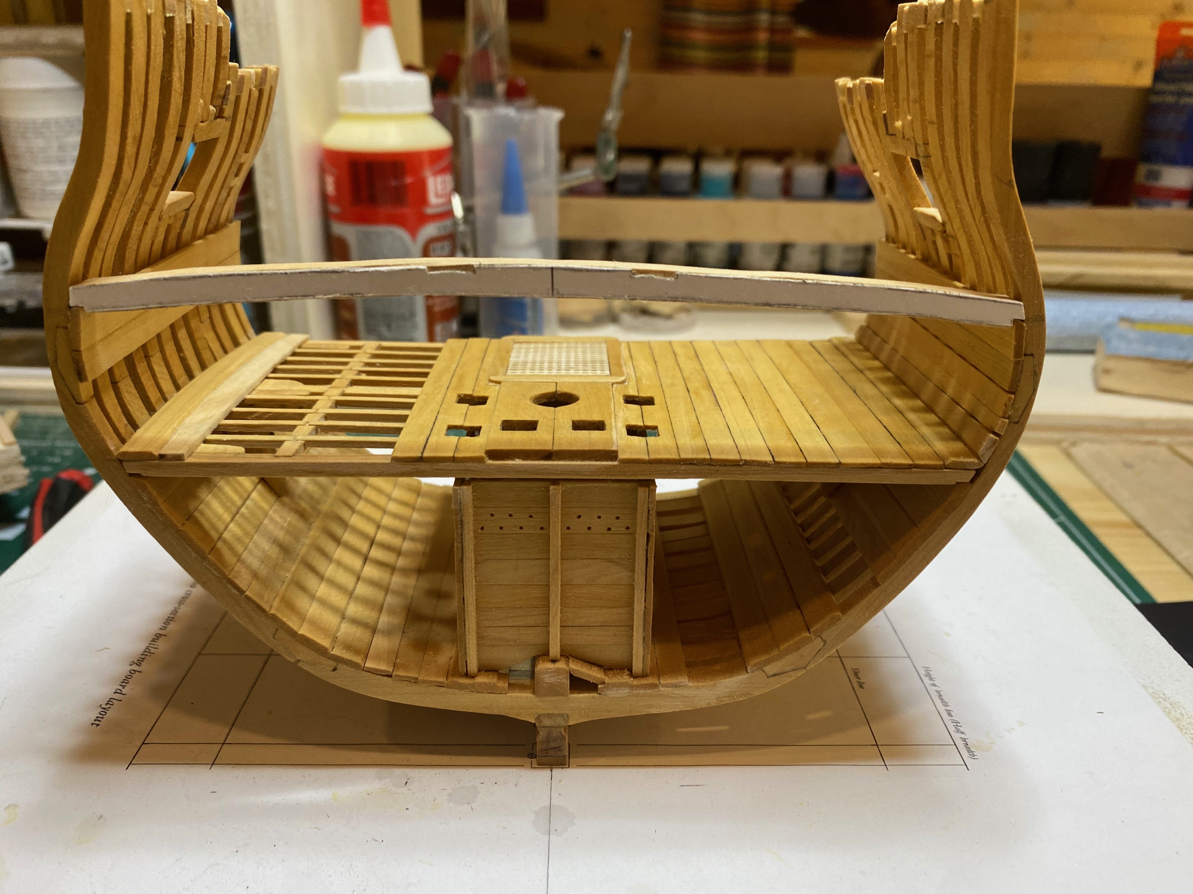
After another relatively long break, I've managed to find a bit of time to work on Echo this afternoon. No great strides forward, though I did manage to make a test of one of the upper deck beams. I made a template out of card paper using the drawing in the practicum against some carbon paper, and then rubber cemented this to some 9" boxwood that came with the original framing package. I think that next time I will simply use copies of the drawing itself, printed onto card. I think this will likely lead to a more accurate template and a better result. Fortunately I have enough of the 9" box to do a bit of testing before committing to anything.
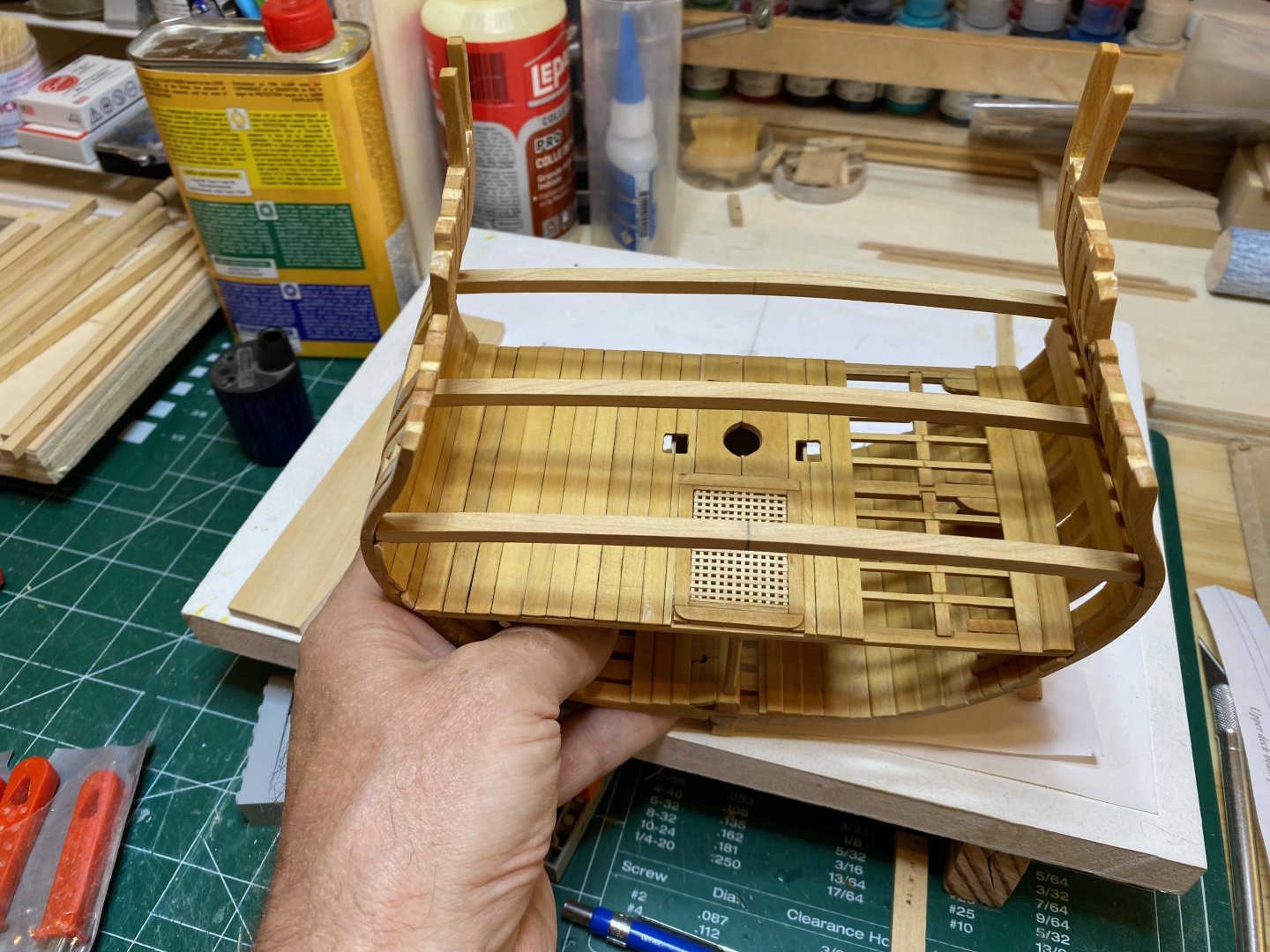
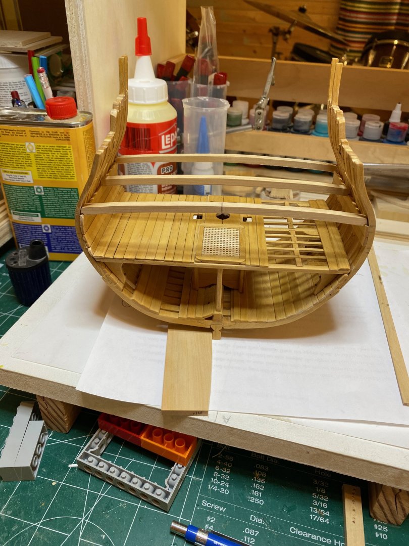
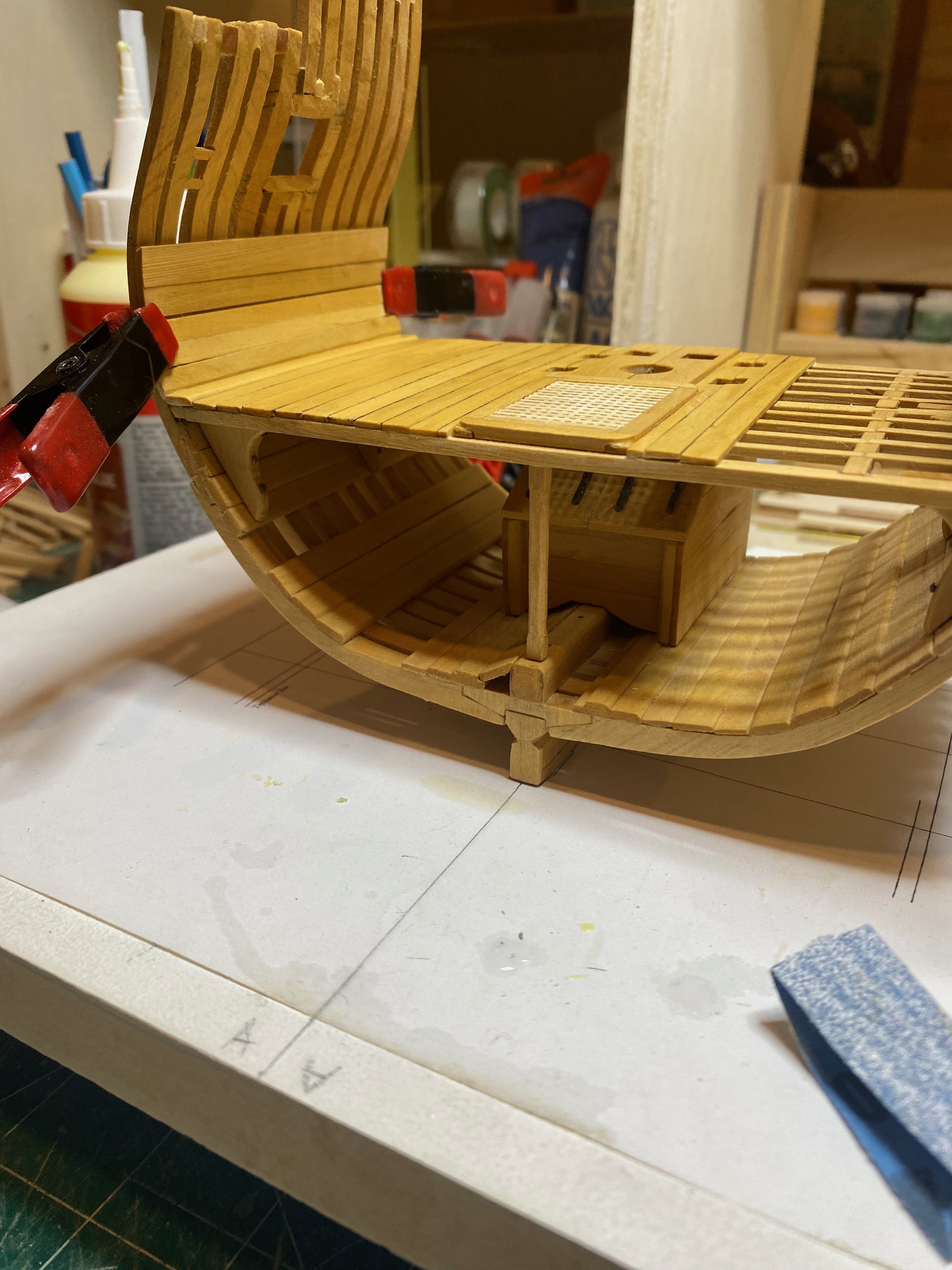
I had imagined that the test beam would be fit forward, but it ended up being a fraction to short for that purpose. But it fits perfectly athwartships in the aft beam position at frame 5. So even though right now the piece still looks very rough (as seen in the photos below) I hope I can tidy it up and perhaps use it since it does fit so nicely....I also made a strake of deck planking to fit in line with the port side lower deck waterway - not too difficult or exciting.
The upper deck framing is going to be quite tricky I think - I'm not looking forward to making and fitting the beam arms and am a bit concerned about the beams being at the correct height.....but we'll see in the next little while how it comes together.
Enjoy the photos and bye for now
hamilton


- Knocklouder, BradNSW, KARAVOKIRIS and 9 others
-
12
-
-
-
At this scale the rigging gets very crowded indeed - I followed Lees for the entire rig of my version of this kit - it was a challenge to get everything just so, but Lees facilitates things through his period-based breakdown of rigging practice by period and rate. From what I've read here, Lees is a very good standard to work to.
I also have no idea what the logic was behind the reversal of the preventer and stay in this case - but as we see all the time, questioning people who've spent their lifetimes learning about specific things is a good way to get things wrong, while following them is a good way of learning how to do things right.
hamilton
- Srenner and Old Collingwood
-
2
-
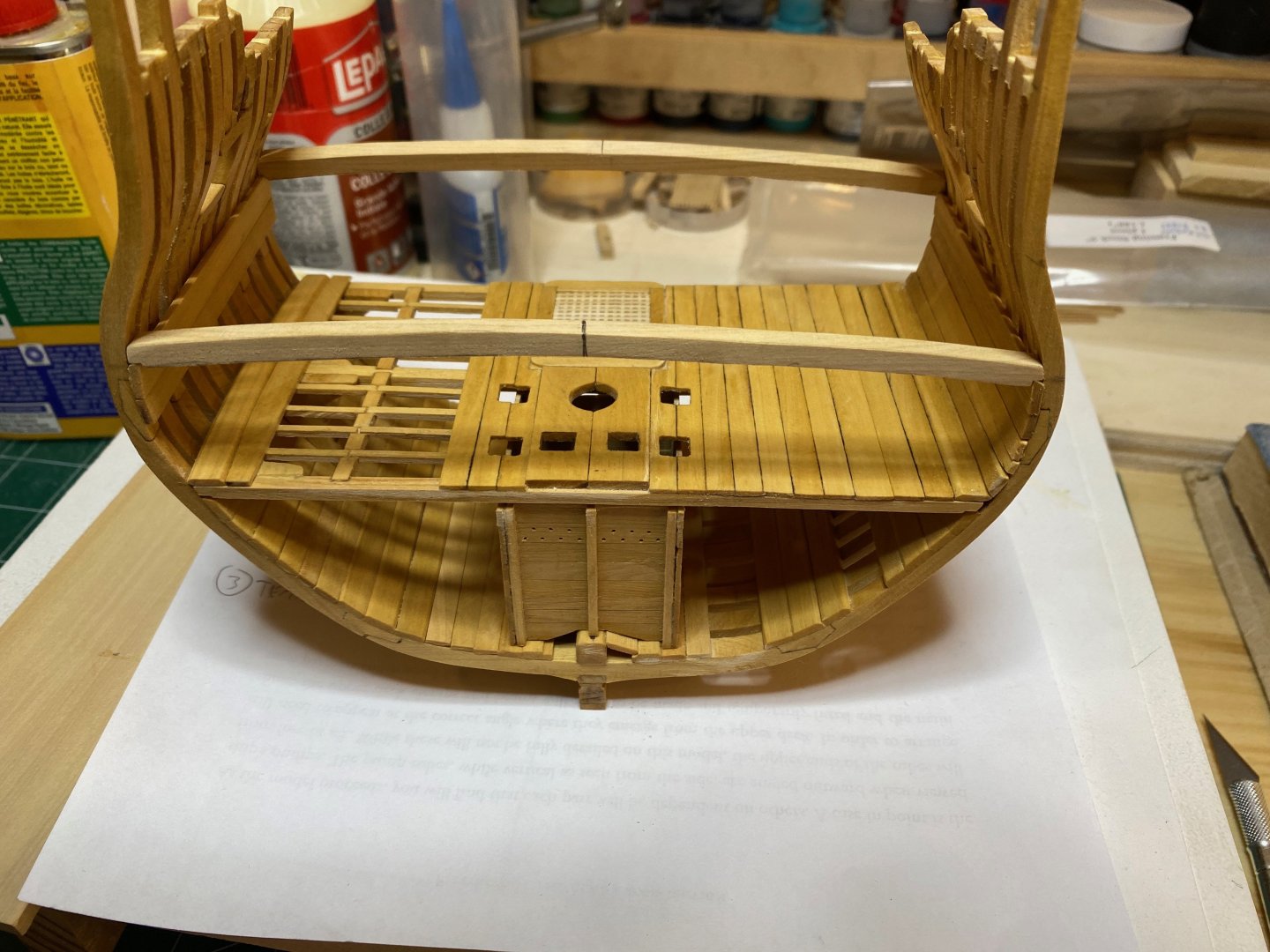
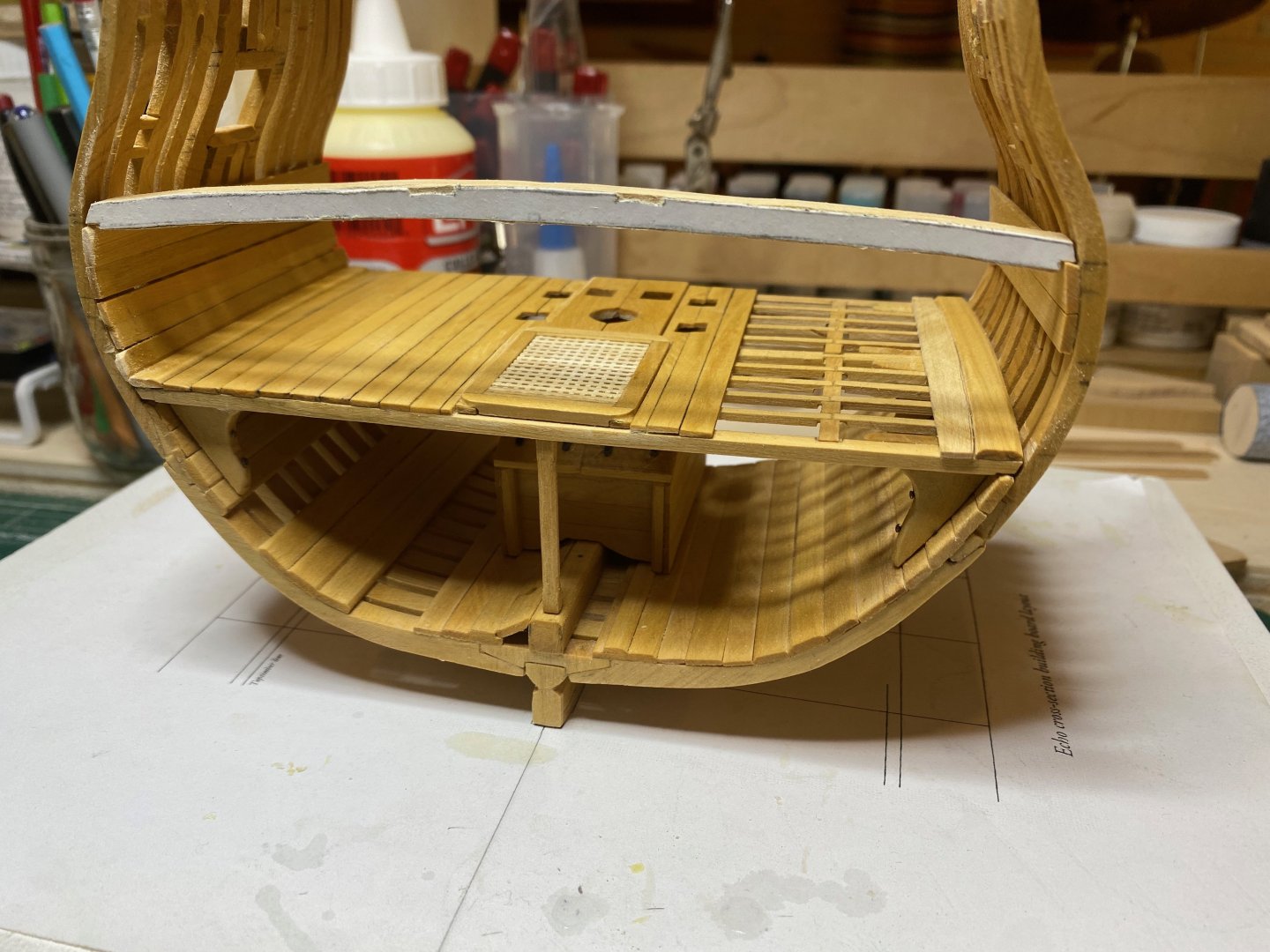
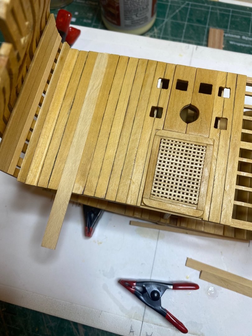
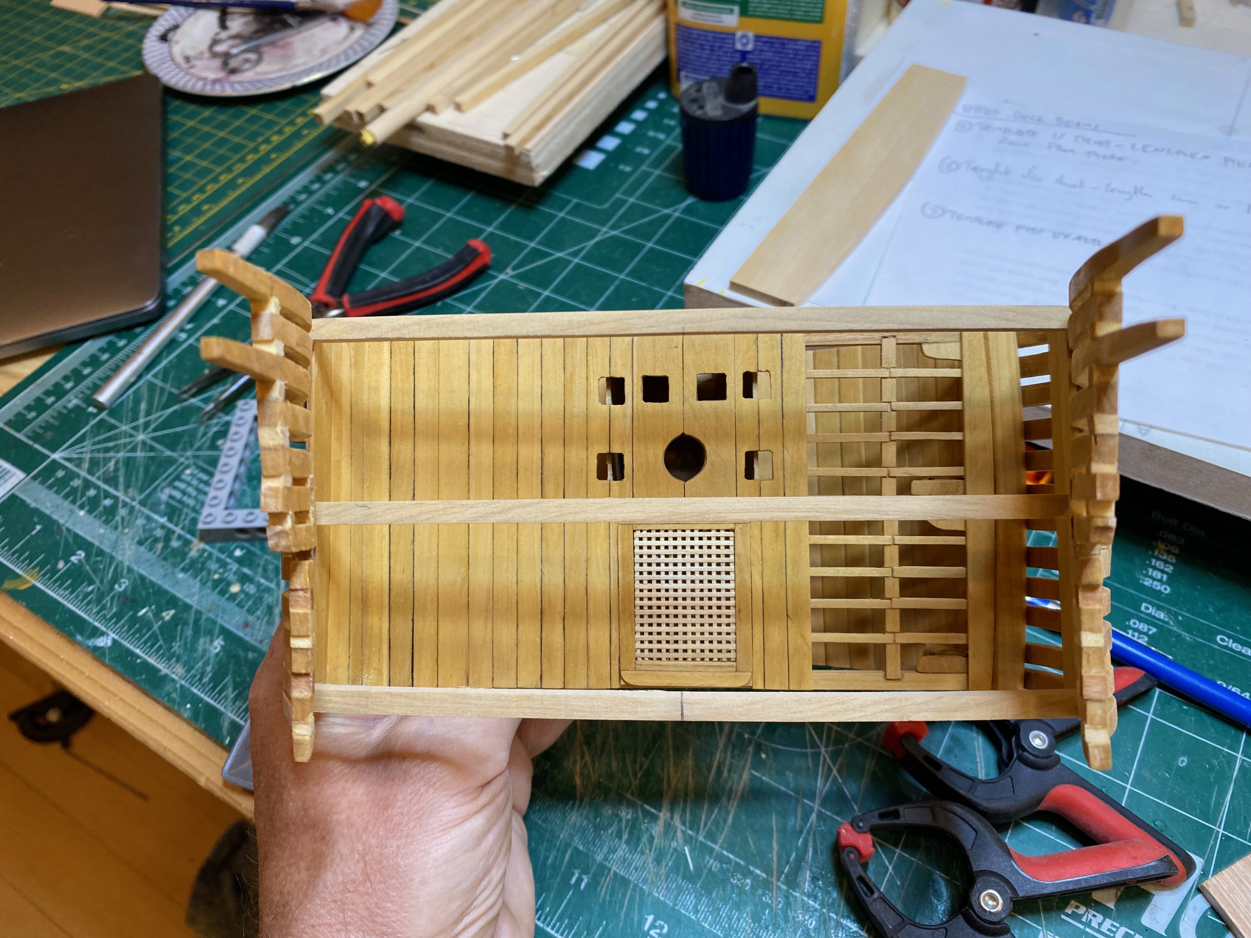
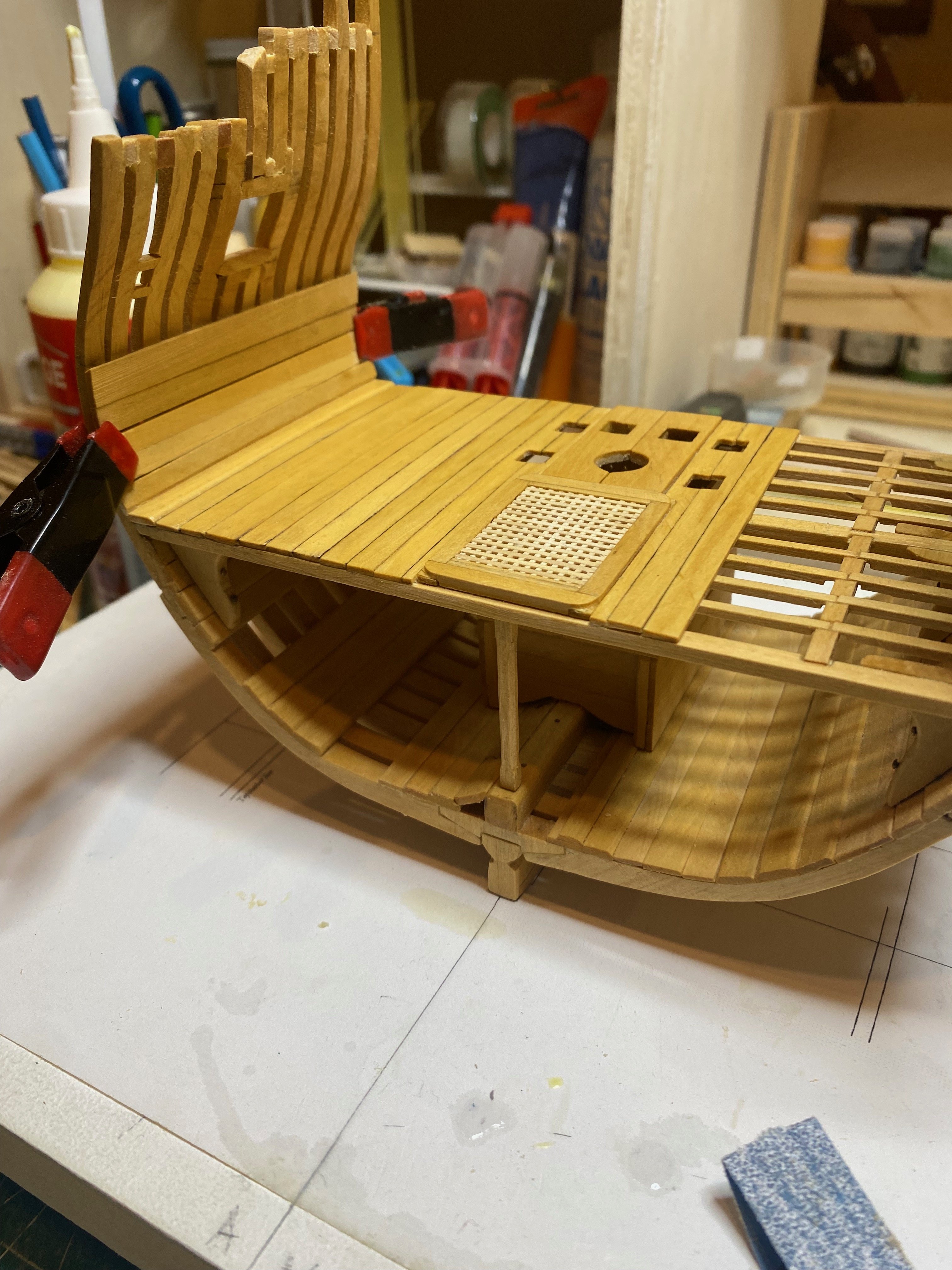
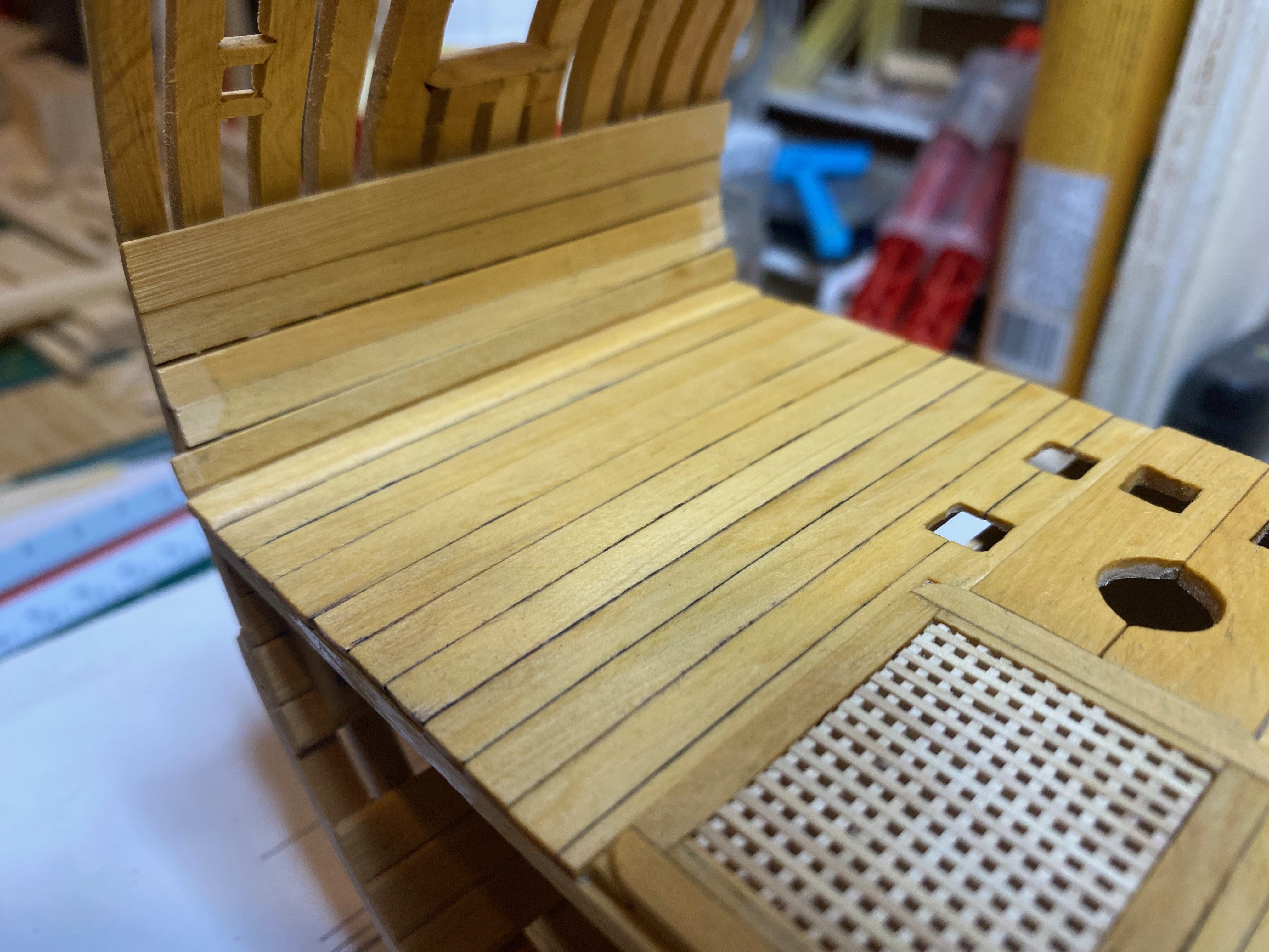
Last update of the day....the lower deck planking is now done, as are the ceiling planks on the starboard side. I ended up using 1 12" plank to round out the deck planking...it stands out a bit, but hopefully when the upper deck is done it will be a bit less noticeable. Bye for now
hamilton


- Stavanger, Thukydides, yvesvidal and 7 others
-
10
-
Managed to install a single ceiling plank this morning and to mill the remaining strips for the lower deck planking. I will have to fudge the planking a little bit, as the space to be filled is not exactly equal to the number of 10" wide planks that will fit there - there is a roughly 2" space remaining, so I'm going to mill a couple of 11" strakes to compensate for this - hopefully the difference won't be too noticeable at this scale.
I'll also need to figure out the spirketing plank on the port side - this will require some spiling to fit against the curved waterway. I won't be fitting ceiling planks on the port side, in line with the overall concept of alternating the planking decks and hull) port and startboard. Externally, I'll plank the port side but not starboard below the wales, but I won't leave the frames exposed at all above the wales.
hamilton
- JacquesCousteau, davec, druxey and 3 others
-
6


HMS Sphinx 1775 by Ronald-V - Vanguard Models - 1:64
in - Kit build logs for subjects built from 1751 - 1800
Posted
A cosy and well-appointed space, Ronald! But it is really that tidy all the time?
hamilton