
Haze Gray
-
Posts
223 -
Joined
-
Last visited
Content Type
Profiles
Forums
Gallery
Events
Everything posted by Haze Gray
-
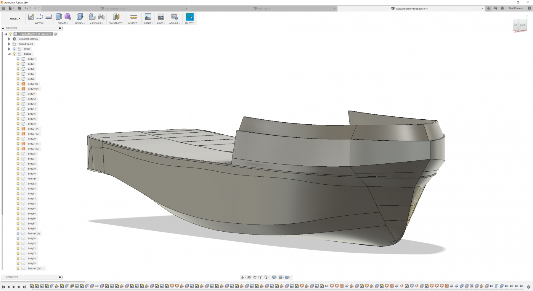
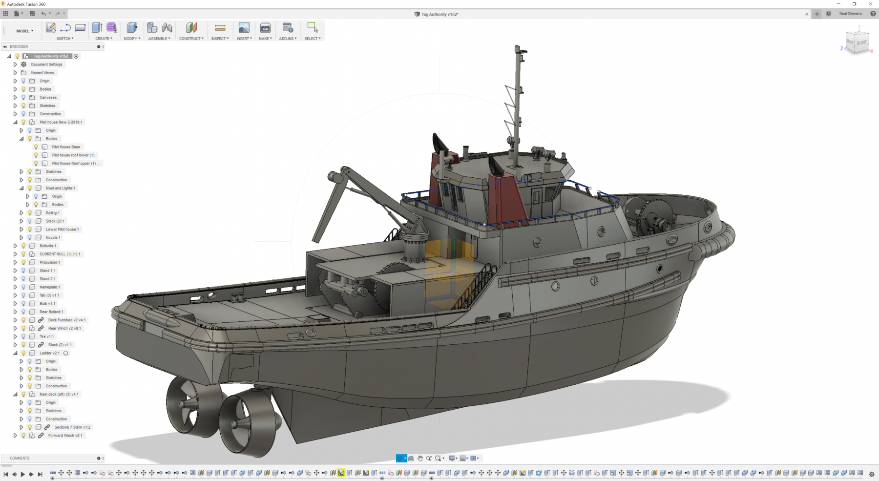
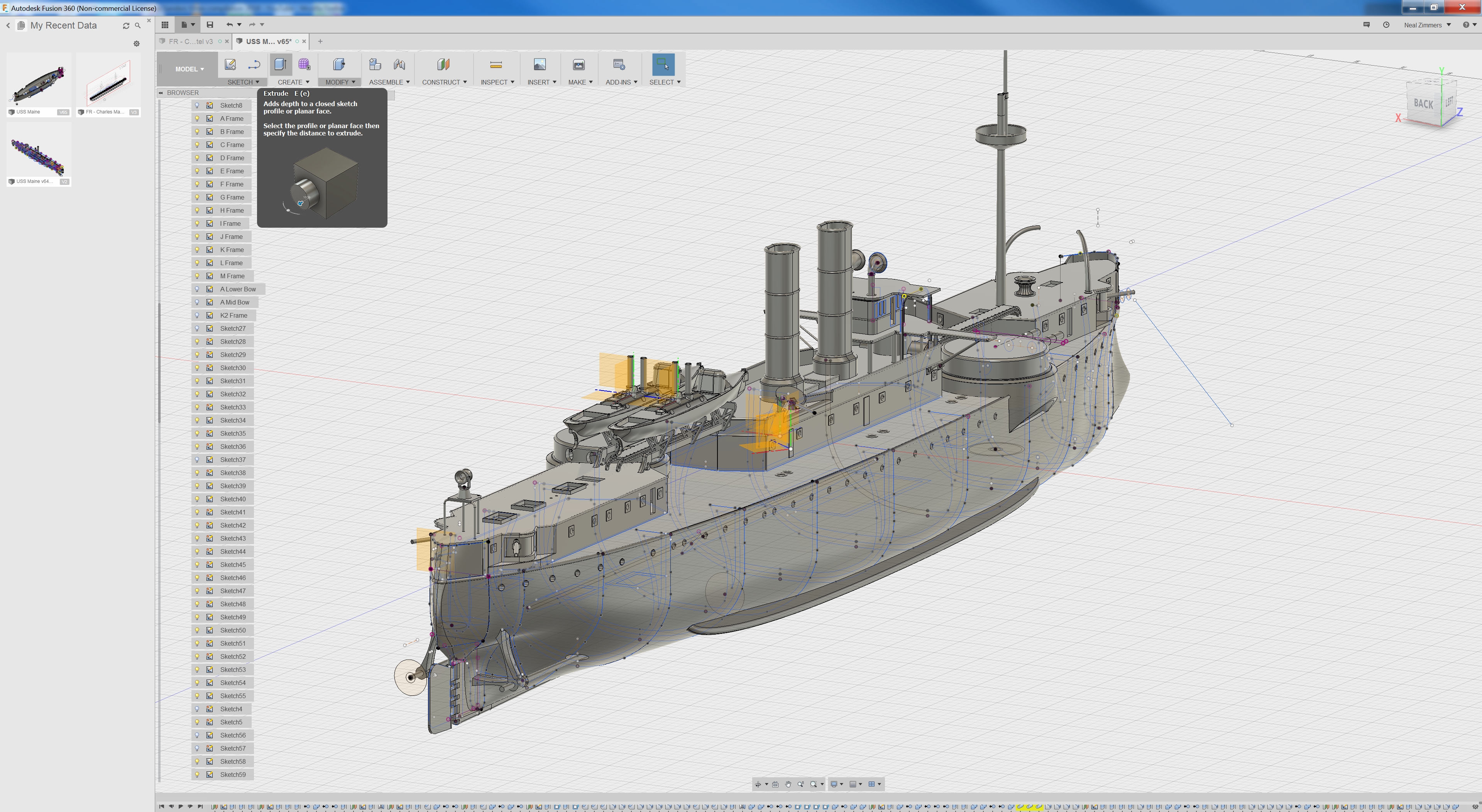
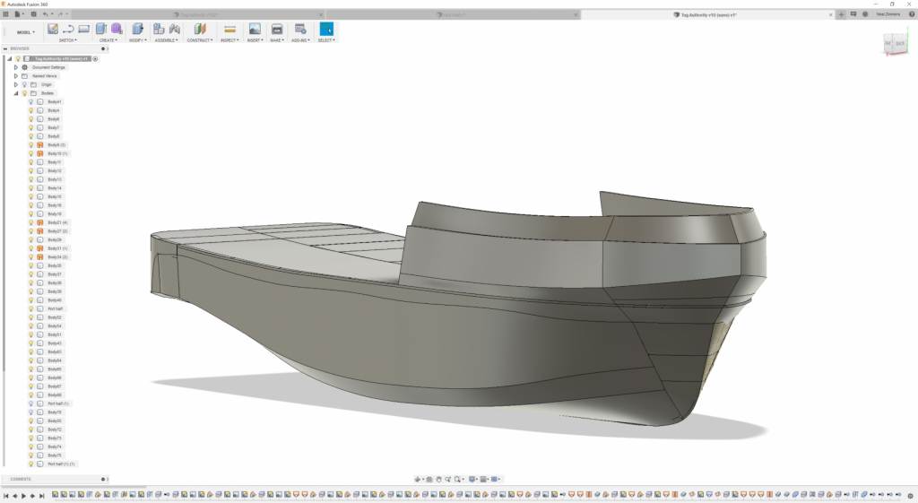
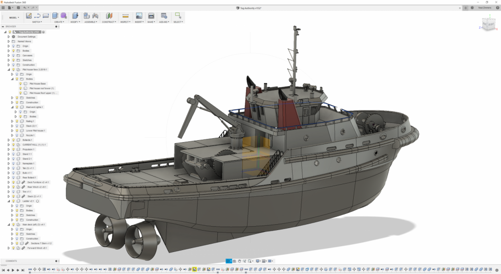
 LOL I was trying to keep a low profile -! I actually went through 4 iterations of the hull if you can imagine getting 12-20 hours into something and going "nope, not gonna work". I'm including pictures showing versions 1,3, & 4 - version 1 was some experimentation I did when it looked like all we would have to go on was 7 photos of low quality - version 2 had only a few partial frames to work with and no general arrangements - gleefully deleted cause I hated it so much which is why I can't show it - Version 3 we had gotten just maybe not quite enough and I had to leverage some schematics of a similar tug to get there. - Version 4 was completed using about 20% of Version 3 and about 60 photos from an on-site visit of the tug which turned out to be critical in completing the design The promise of 3D printing boats (or anything else) are perfect parts, that fit together perfectly, perform and look perfect. - Unfortunately there are multiple realities (some of them good, quite a few of them bad) when you actually attempt it because the printing part is experience, skill, and science driven - but I don't think that's different than any construction technique - I remember building a FW 190 out of balsa from a Gillows kit in highschool - glued it all together perfectly but the balsa was green and when it dried overnight the fuselage was bent like a banana - totally unusable. For me - I'm all in on 3d printing - probably because I can do all the design work, planning, and integration of elements which is a very pleasing part (and I do okay with the printing quality!)
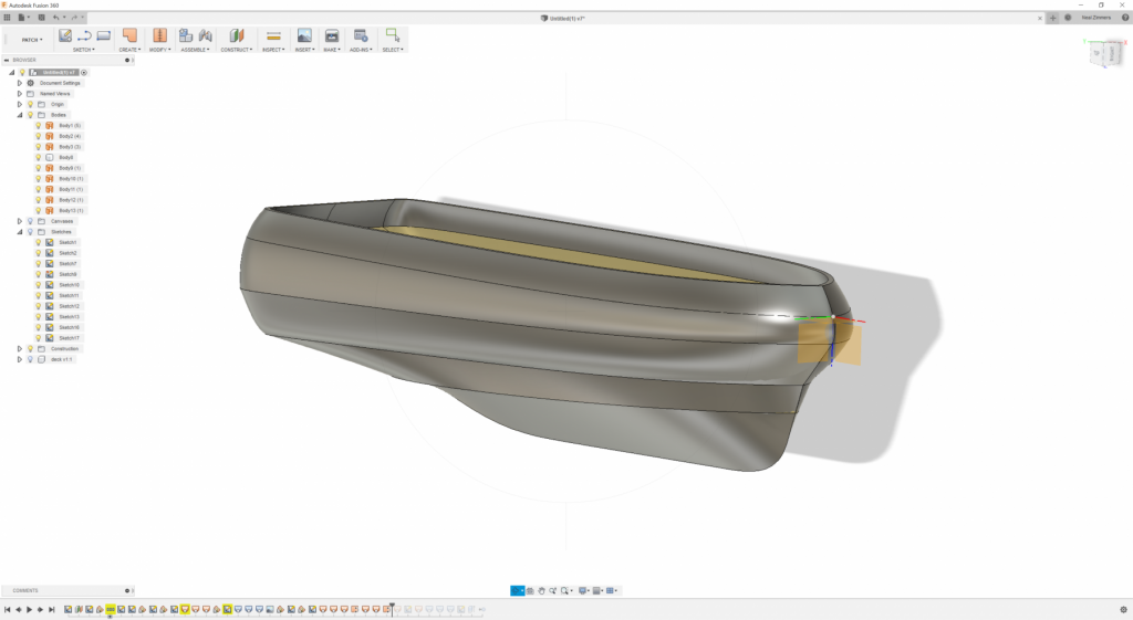
- 133 replies
-
- 9
-

-
- alert class
- tugboat
- (and 1 more)
-
Hi Ben, The way it works is actually only 1 magnet (neodymium) down at the bottom of the hollow column (basically a pipe), the base of the water cannon has a step in that narrows down the end to fit into the column but at end of it is a steel screw - steel screw contacts and is held in place by the 5mm magnet - two magnets might work but the steel screw is adjustable ensuring proper contact.
- 133 replies
-
- 5
-
-
- alert class
- tugboat
- (and 1 more)
-
Hi Ben, I contributed to the project a bit - the school wanted certain features and one of them was for the nozzles/water cannons to rotate - and the thought is the magnets would allow for the 360° rotation while also being easy to replace should they get snapped off by enthusiastic students. There's a couple of other components that were made to allow for removal and replacement (pretty much anything that was going to be actuated or manipulated by hand).
- 133 replies
-
- 6
-
-
- alert class
- tugboat
- (and 1 more)
-
So I ended up ordering a Folger FT5 printer kit (basically an H-Bot type printer) I am definitely going to need more printers but I want to try out building a kit to see what I want to change and at the same time I'm intrigued by the H-bot style where the build plate only moves down and the print head moves in the X/Y planes. I really need about 5 -6 printers but not sure if I have the space in man-cave for them. Also, will need to spend some time on constructing the mikasa in Fusion 360- that was a fun excursion and visit on that ship! I have more than enough data on the boat (actually I have photos and data on about 250 ships at this time and 2TB+ of photos plans!)
-
Yes, interesting isn't it? Would absolutely be ideal for smaller detail parts, infact...I suspect you print 100 railing posts at the same time just as fast as printing 1....there's no time penalty to printing multiple parts as it prints any layer of all parts at the same time not one after another..... 1L is about 1kg, so if $70/L it's easily twice as expensive as typical filament for your average fused filament 3d printer.
-
I'm in the market for another printer (it would cut the printing element of my development time by 50%! which would be a BIG improvement) and you would think that already having one printer would make it easy for me to choose what my 2nd one would be but all I have is an ever expanding list of wanted features! I'm suddenly interested in the DLP and SLA as they have some great resolution (anycubic photon DLP is ~$500!) but the limited size and resin fumes and need for post wash and cure is troublesome. The typical FDM/FFF is still a nice solid bit of technology that's easy to use and affordable but has some inherent limitations. If only there was some SLS printers in the 250mm cubed range wth 0.05mm layer height that were affordable, that would really open up possibilities.
-
Very much Appreciated the invite and wish I could have stayed longer. Will certainly come whenever I can, Good bunch of fellows you have there! Will have to touch base with you when I get back in Seattle next week!
-
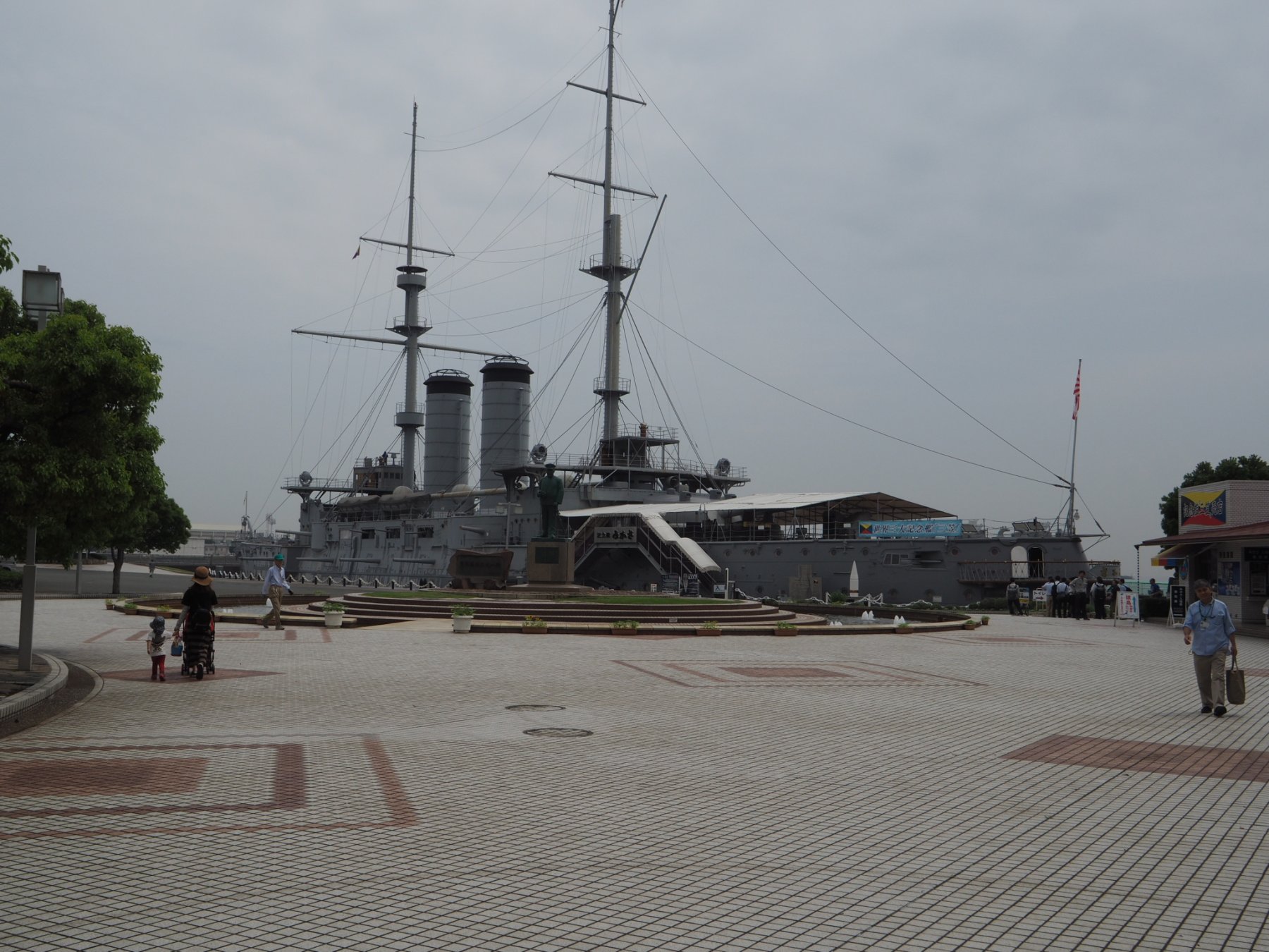
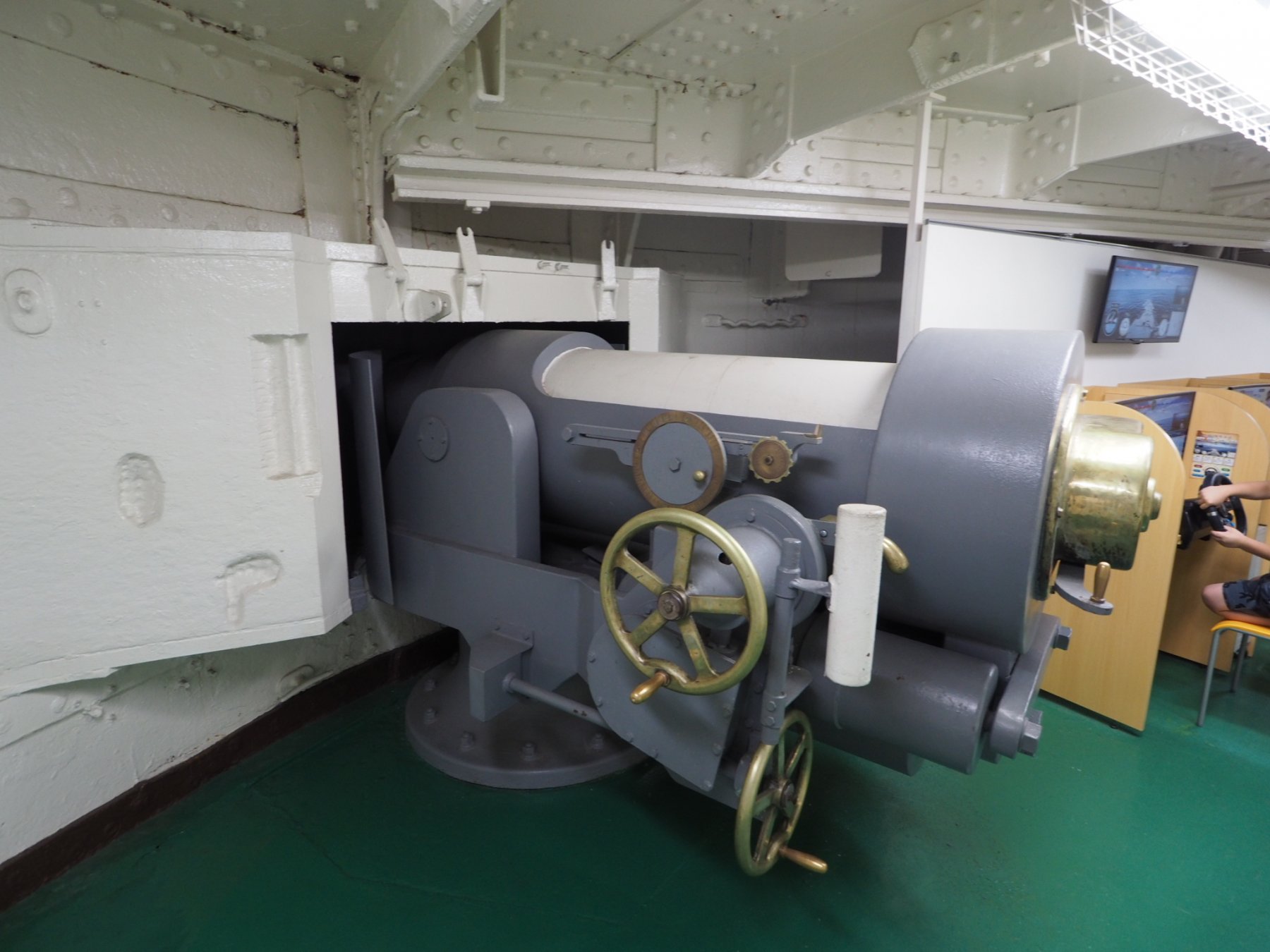
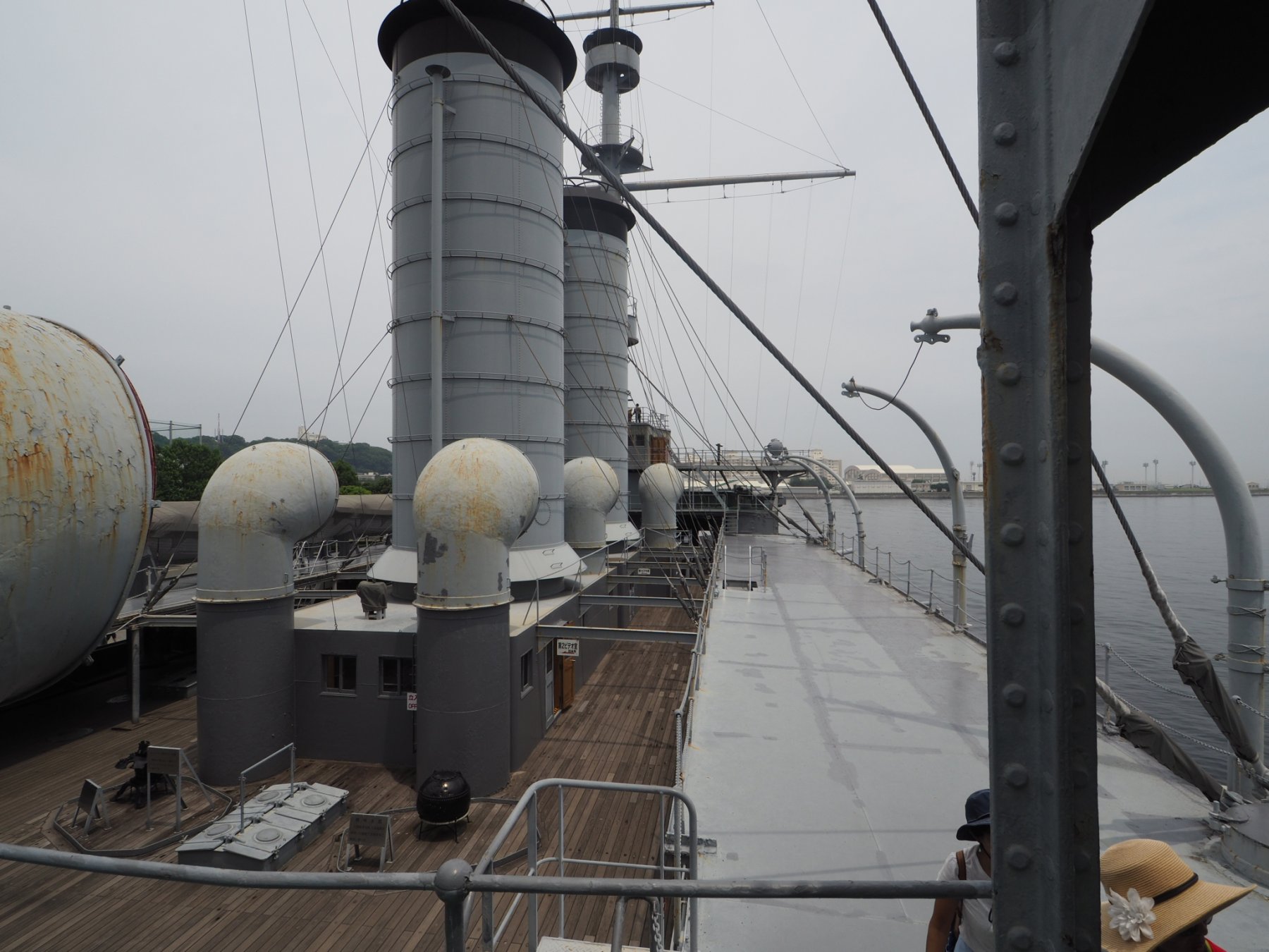
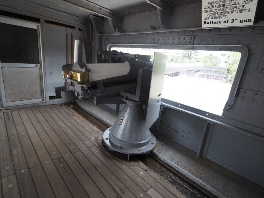
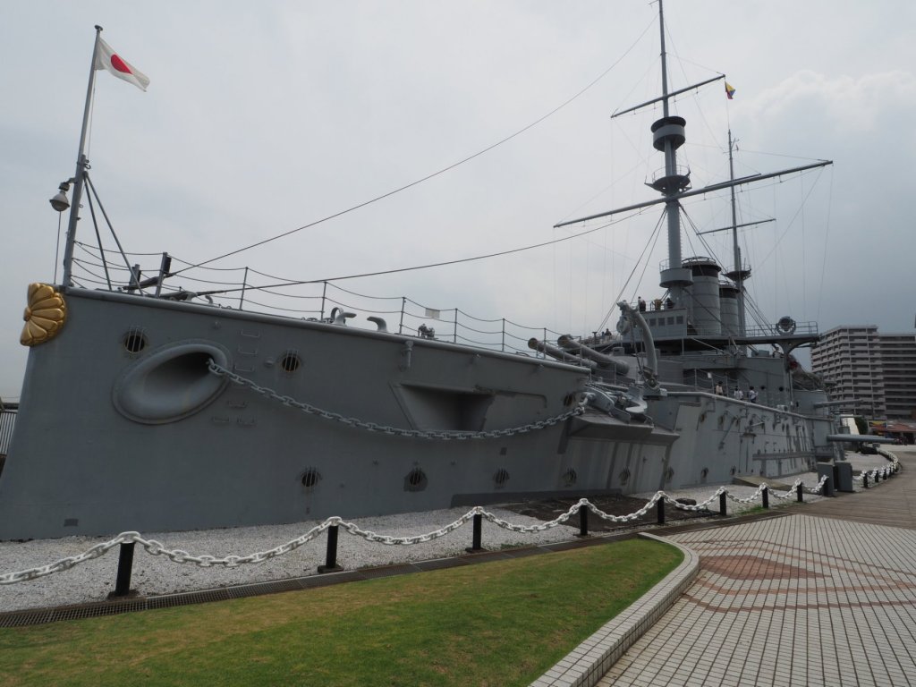
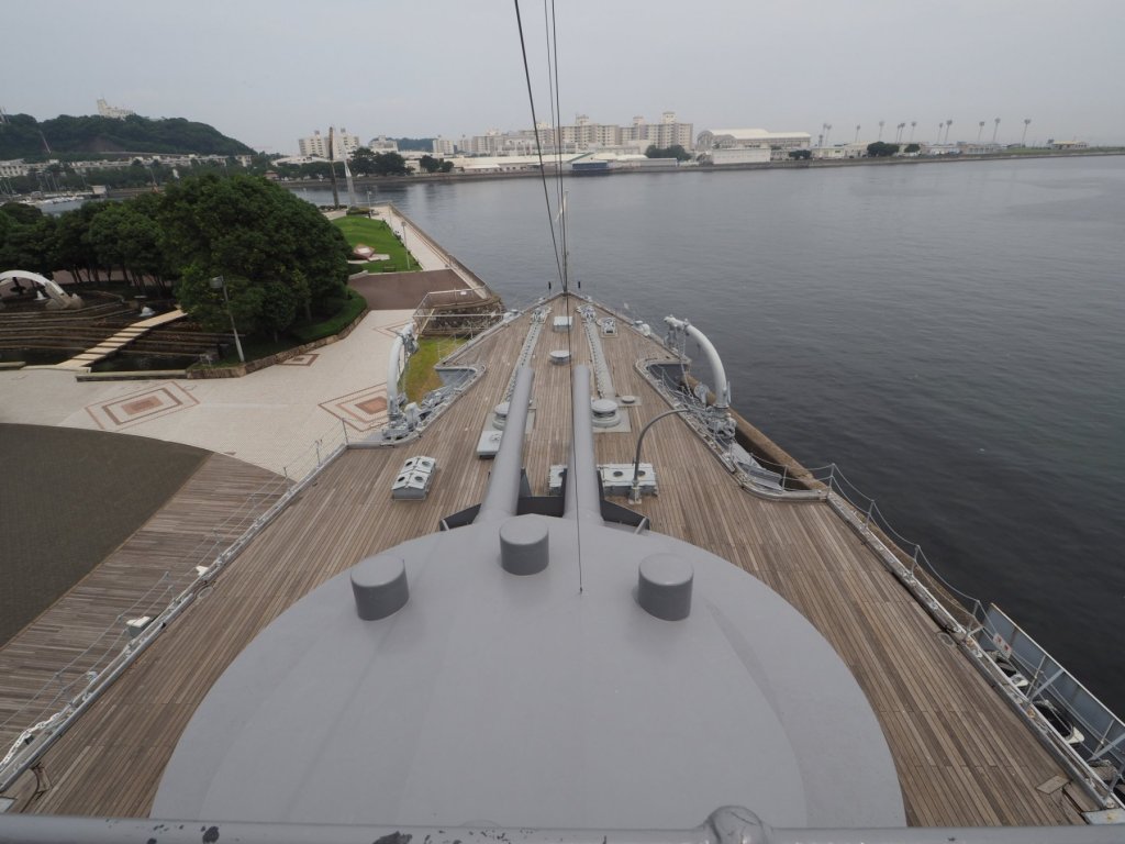
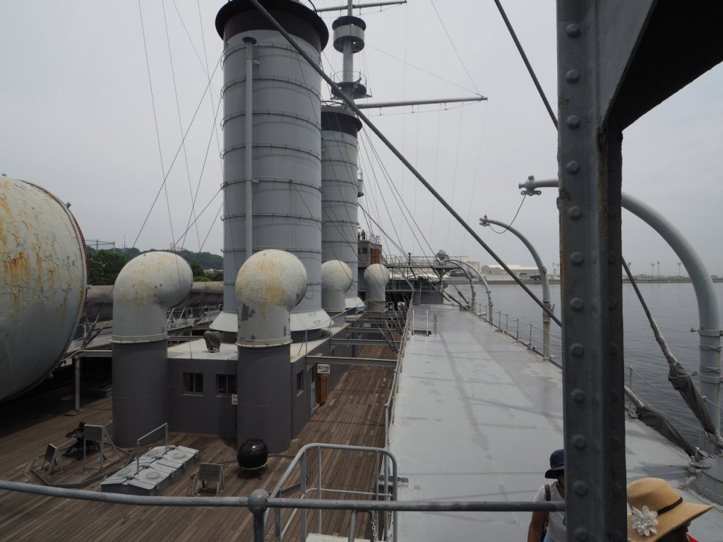
Off on vacation this week but will post a few pictures of the hull of the Maine when I get back, the name plate on the stern of the boat did print out and didn’t look bad at all. So, vacationing in japan, not too far from Yokosuka where the (pre-dreadnaught) Mikasa sits, had to stop by, pretty interesting, couple photos of that ship....


-
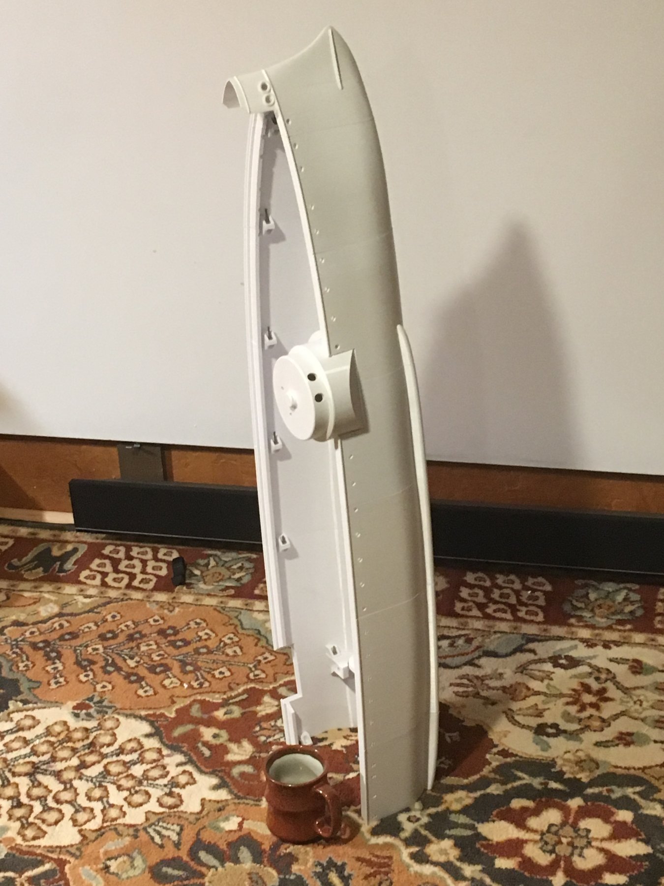
Good morning, another photo and getting closer- last section will be done this evening. I’m also going to start experimenting with printing at 1/96 scale which could be a good compromise between size and presentation.

-
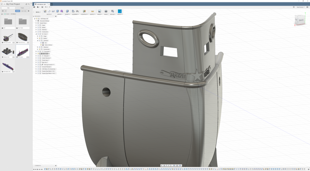
Okay, I just had to give this name plate a try - 2 hours later..... it has the similarity of features but obviously not what I would call close... will be fun to see how much of it comes out in printing. one of those things that would be way easier and much better if just done by hand !!! (and Yes I need to adjust those ports for the stern lines but that's easy) Also hull in the photo is 80% printed, working on last two sections!

-
I’m using 3mm filament and a 0.4mm nozzle, most of the sections I do at .14 layer height but a few are at .20 layer height.
-
A couple more photos that I was able to take this a.m. keep in in mind that while the prints you see on the photos are good, they are not super great or anything... iPhone camera is designed to make anything look good! theres a few sections in the hull that have different settings, I find pretty much that increasing layer height means taking a hit in print quality but I haven’t quantified exactly why that is. I think it has something to do with thermal expansion of the material at higher flows.

-
Okay had a bit less time than I was anticipating this weekend, bunch of kids sleep over for a birthday - but did manage to get a few more sections attached. Also test fitted turrets but no photo of that yet. ts but no picture yet
-
I’ve not heard or tried onshape, but I looked into it this a.m. seems there’s a lot of similarity with fusion 360 in terms of how one operates the program. Watched a few videos comparing fusion and onshape- seems the recommendation for one or the other hinges on how invested you are in a platform. I plan plan to tinker with both onshape and deftship this weekend to see if they are easier to use and yield better results for hulls.
- 132 replies
-
- 4
-
-
- charles martel
- battleship
- (and 1 more)
-
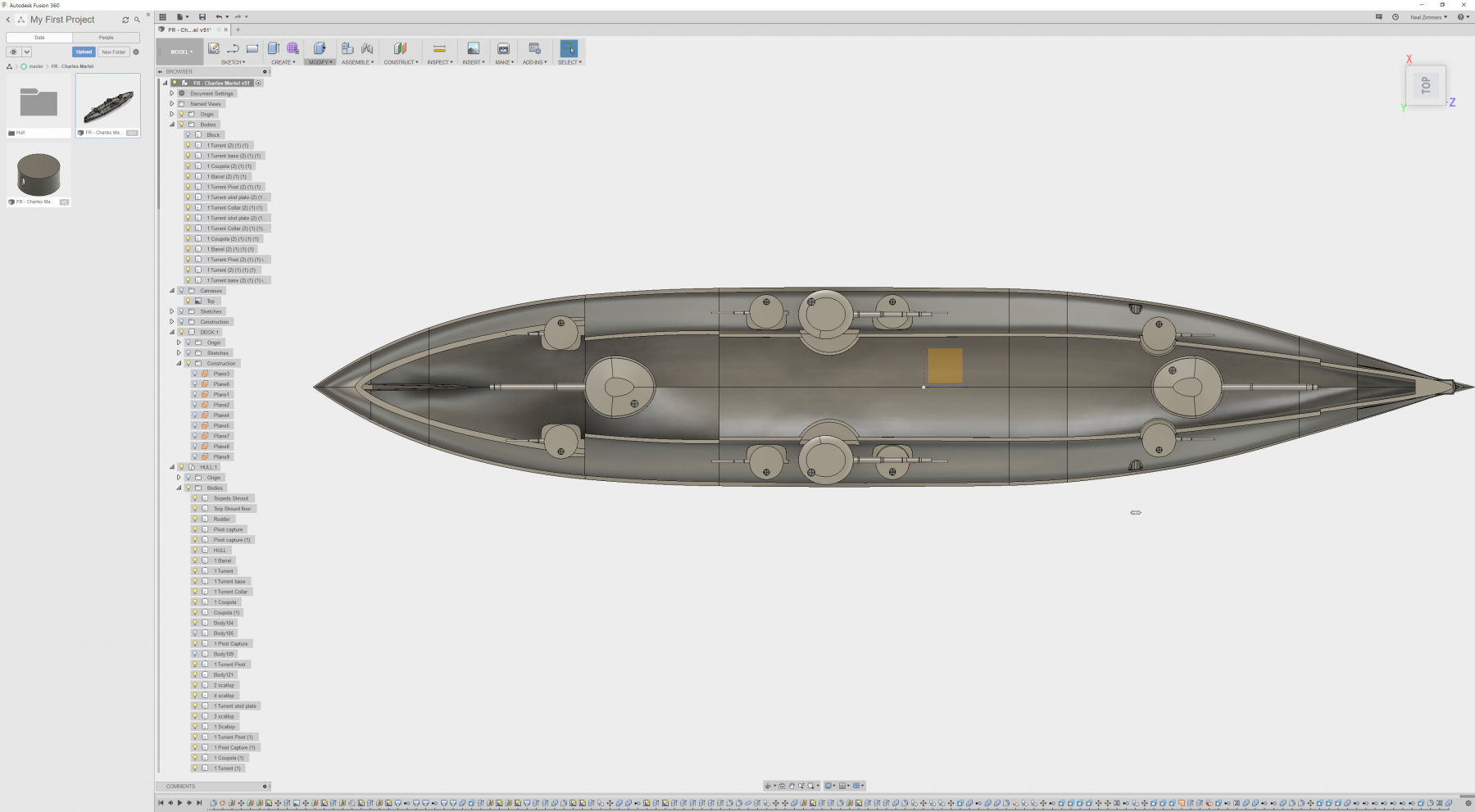
Ha! I think it's more like my Fusion luck! I've done 3 hulls after the Martel and they are not anywhere as good and here I thought I was improving. Lofting in Fusion 360 is like some kind of mystical art - I've noticed that sometimes the success of lofting depends on the angle you're viewing the model from (crazy!). I'm starting to take a look at the Deftship software and if I can import a model from Deftship into Fusion I might actually try that route. Also, I went with my standard 5mm hull wall thickness on the Martel - and wish I had gone with 7mm as the hull is a really big shell with a much smaller deck that is far from the keel - I should be able to go back and adjust the offset of the frames but that's not really possible - maybe the way I'm doing it is wrong but when I do a hull when I get done I've forced more than a few errors and while the loft result is good - the "mold" that created the hull is more or less destroyed in the process.
- 132 replies
-
- 5
-
-
- charles martel
- battleship
- (and 1 more)
-
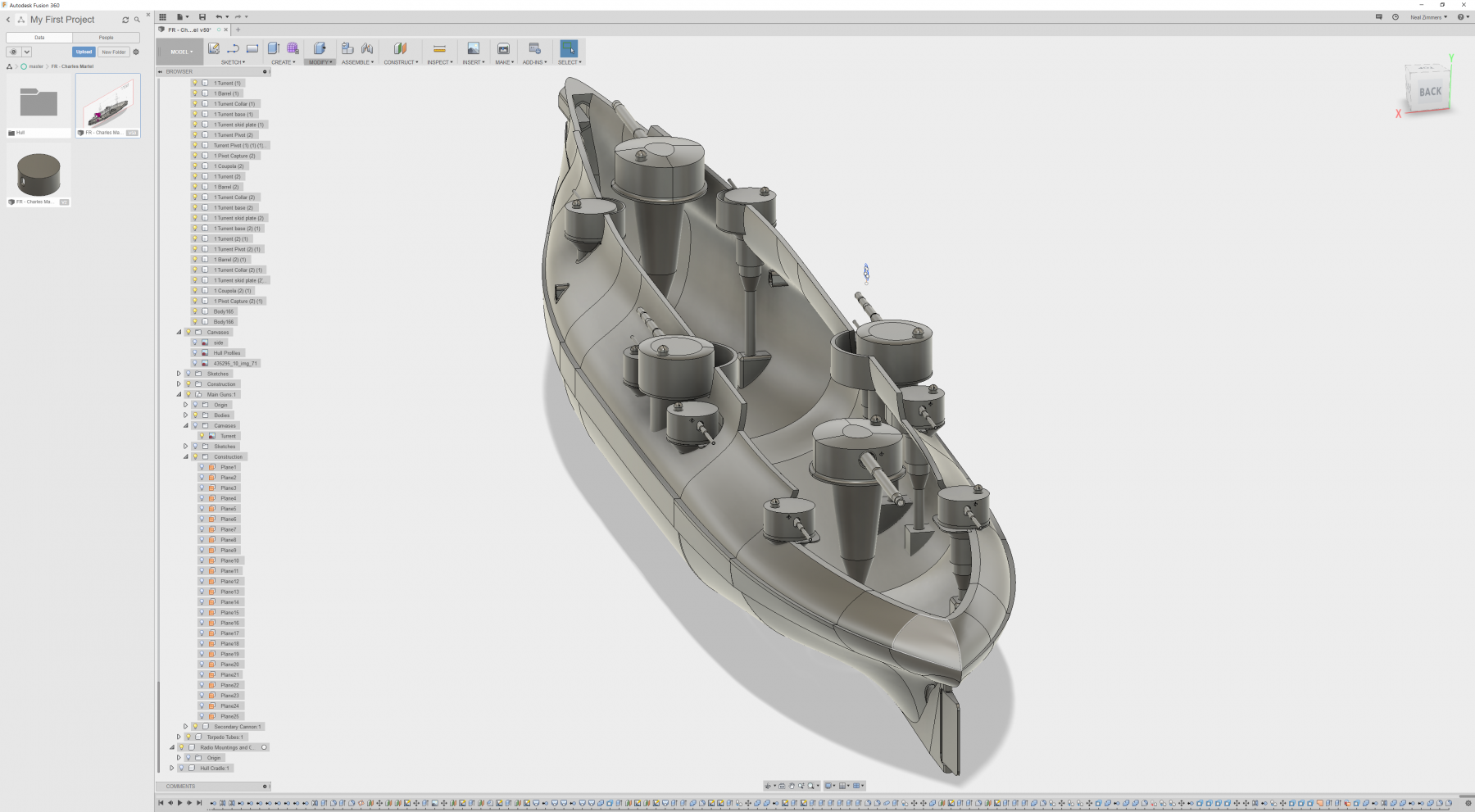
Thought I would provide an update - it's been about 3 weeks since I posted and mostly I've been working on three other ships since I needed to take a brake from the Charles Martel - so tonight I spent about 3 wonderful hours on the boat this evening and I can tell you this is one fun boat to build (and challenging too). About 1.5 hours was spent on just examine photographs and double and triple checking the shape of the two main turrets. Pretty much all the photos of models I have seen have all the turrets round - which is incorrect, main and the large secondary are oblong to accommodate the long breach of the french barrels - I was even able to track down some engineering drawings to confirm. so, all the turrets are in, now according to my own notes I am supposed to work on the propulsion and the pulleys for the tramming of the turrets. not as sexy as working on the superstructure - but once I get the internals done it will be a relief to have that behind me and I can attack the desk and the superstructure with complete abandon. I've even been considering putting in the spiral staircases in the fighting masts and that has me thinking about what it would take to fork off what I have thus far and make a version that's visual model with one side of the hull open and the various internal decks with details of boilers and the steam engines... I built over plastic 100 models when I was a kid and kind of still have that itch about internal details being an important and pleasing commodity. Anyways, enjoy the pics.


- 132 replies
-
- 12
-
-
- charles martel
- battleship
- (and 1 more)
-
French Pre-Dreadnought Battleship Carnot
Haze Gray replied to dgbot's topic in Nautical/Naval History
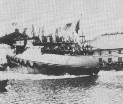
Hi Roger, Pretty sure - I've attached some pictures of the launching of the Charles Martel + a hull slice from the aft section of the boat from the French Marine Society. The actual ship may not have been that stable in real life!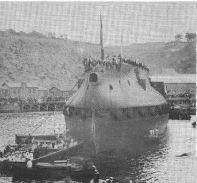
.jpg.4824681d5c382a61d97b3f49d0288c9c.jpg)
-
Hi Tabycz, there’s a lot of good material options out there, I’m using PLA right now for the development prints as I have the settings dialed in for it. ABS , ASA, PETG could easily be used. I will say there’s an at vantage with ABS to join with a slurry of acetone
-
All that's really needed is to paint over the PLA with something opaque enough to block UV, so automotive primer + a top coat will do nicely. I have both an unpainted part and a painted part sitting outside and will check the results at the end of summer to see how they fair in the sun. PLA sensitivity might vary between manufactures depnding on the color/pigment or other material properties.
-
I actually have the Olympia and Oregon on my list - and have the design plates for them - I will say the Olympia has the best ornamentation I've seen on a US steel ship. speaking of Bow crests - I've got these photos of the bow crest on the Maine that eventually I'll work into the model and try printing, will probably need a .3mm or .2mm nozzel


-
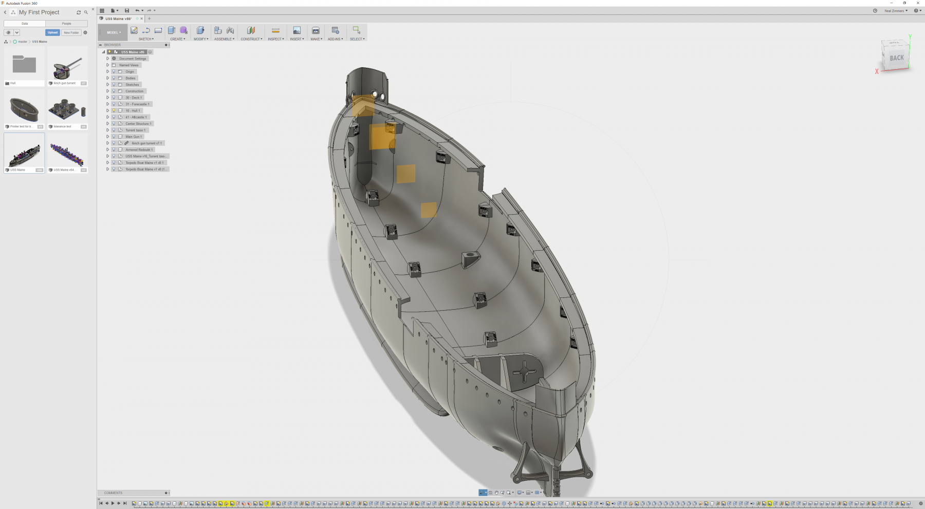
Hi Yves, that's an interesting question - If I were to do a kit I'd like to make it as low a cost as possible, I believe there's about $150-$220 worth of material & electricity that goes into 1/72 scale version of the USS Maine - all the Hull sections together take about 18 days to print in total so possibly 30 days of straight printing for the whole boat. At 1/96 scale the material costs and time is reduced by about 40%. I've been printing parts and adjusting dimensions for tolerances for the 1/72 scale and and there would be a fair amount of changes and lots of test printing to dial in the 1/96 version so I'm reluctant to do that. It would be fun to do a run of kits in 1/72 if I had a bunch of printers - and if I could get the cost per kit really low - so if there's interest I'm happy to sharpen my pencil and get it as low as possible. Over the next week or two I'll have some pics that are going to be really fun to post - Turrets mounted in the hull look really great!
-
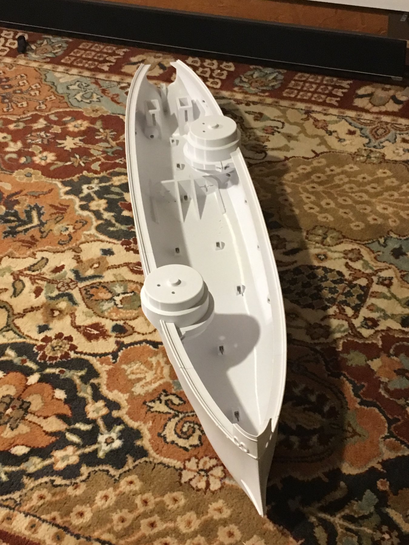
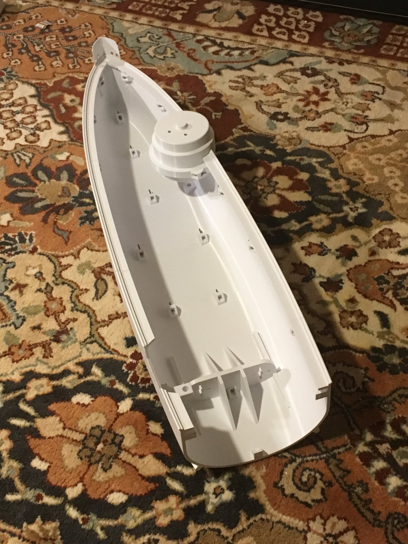
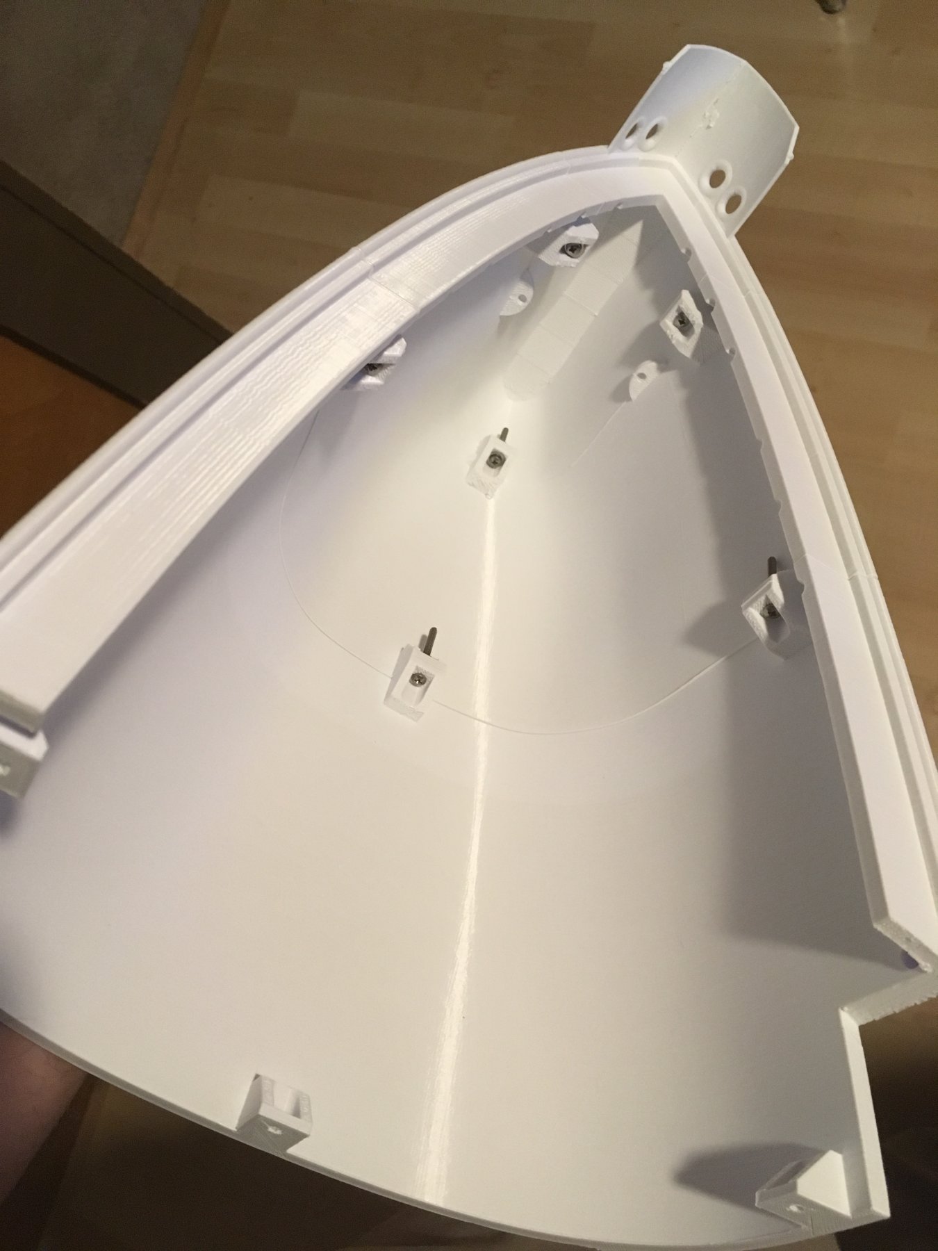
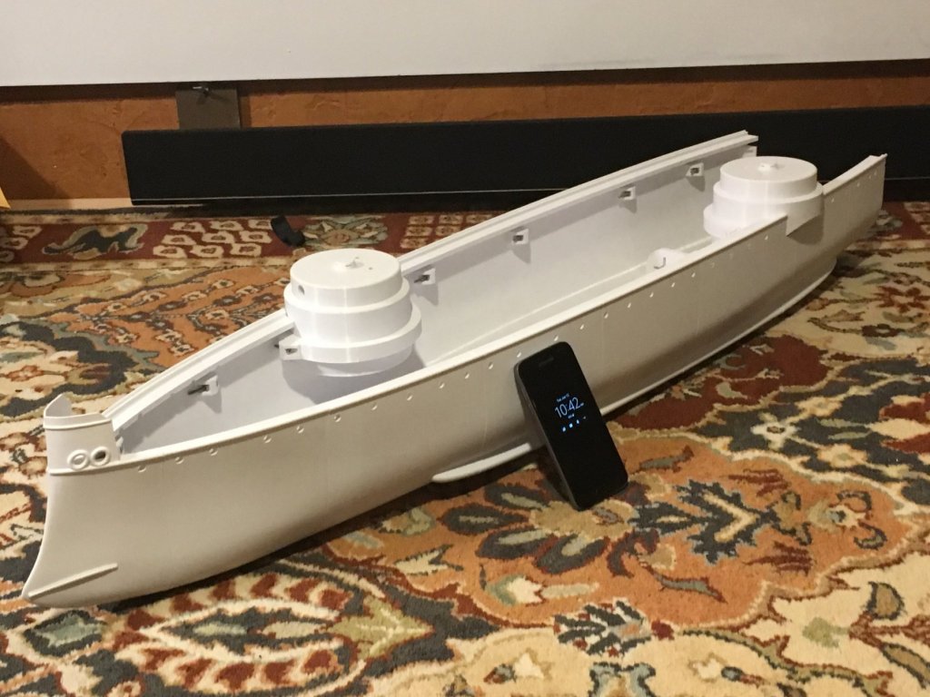
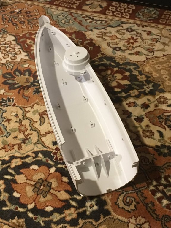
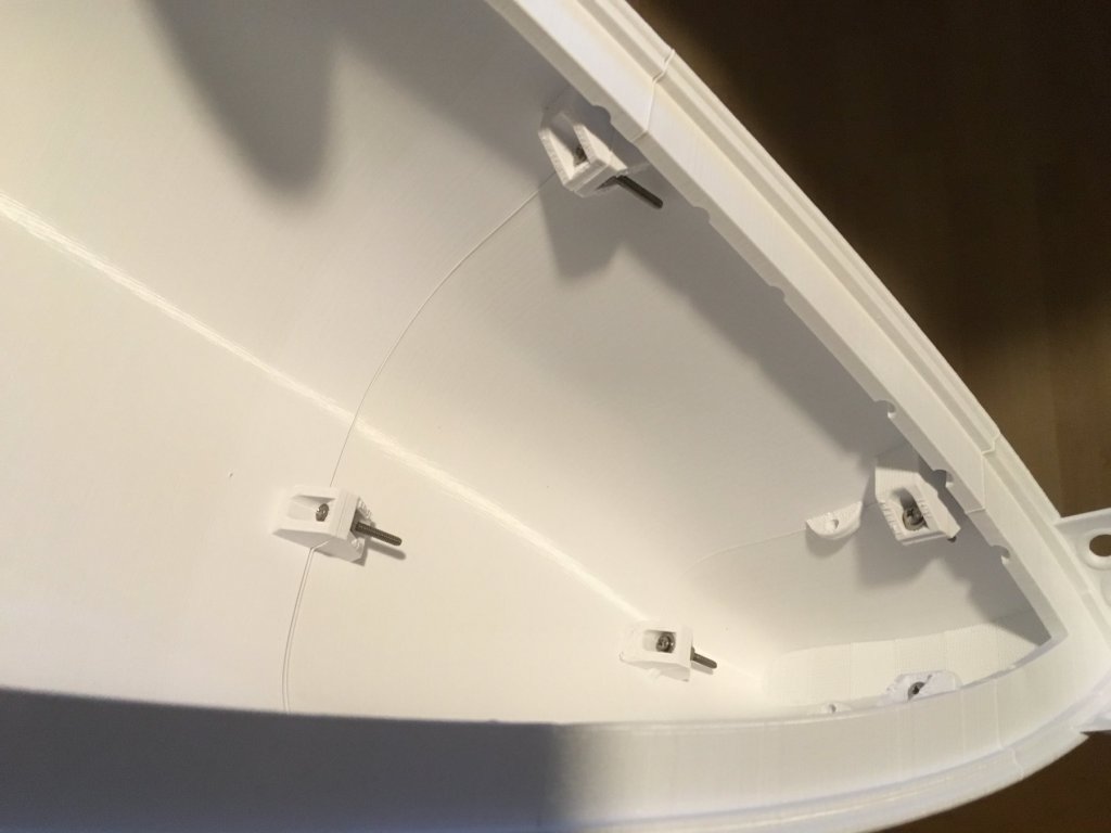
As I have been modeling/researching the USS Maine I've come across quite a lot around the sinking of the Maine, controversy as to the cause, and reports and investigative materiel. There's alot of photos of the wreck after the cofferdam was constructed around the Maine for investigation but there's not enough there to really get a picture or understanding to the degree I could model it - suffice to say the pictures basically show the bow section separated from the rest of the vessel - and the section forward of the center structure essentially a conflagration of metal and essentially obliterated - there's no 'hole' as that part of the ship was simply opened up in all directions. As far as the cause, there's no evidence that would rule out either explanation (external or internal origination of the explosion). Both are a possibility and at least one report I read stated that the damage was also consistent with an internal explosion detonating a mine underneath causing a secondary detonation. CDW is correct, the model that I am designing is intended to float! speaking of which I haven't provided an update lately - so here's a short one: After printing 4 sections of the Hull I realized I needed to reduce the length of the sections (basically shorter ones) and add tabs for nut+bolt joining to ease alignment and assembly of the hull. I've printed out the first 3 sections and the 4th is getting printed as I write this. The tabs work well but do require supports while printing depending on their orientation - I may not go back and re design them but for future hulls in work I plan to design tabs that help capture the nut and don't require supports while printing. Here's a few pictures, as is I am pleased with the results and will continue to improve the approach.


-
Glass works, it's super flat (if you get the right kind) but I'd recommend you hold off on switching to glass and figure out if you need to switch to it - unlikely there's more than a few thousands of waviness on the bed you have, and that gets sorted out within the first 1/2 milimeter.... but if you are thinking of picking up glass for extra beds that's an excuse as good as any in the 3D printing world!
-
Prusa i3 is a great printer from all accounts I have read and seen (and watched) - I think you'll be up and running in short order. Probably the hardest thing you'll have to tackle is filament settings...