HOLIDAY DONATION DRIVE - SUPPORT MSW - DO YOUR PART TO KEEP THIS GREAT FORUM GOING! (Only 27 donations so far out of 49,000 members - C'mon guys!)
×

Haze Gray
-
Posts
223 -
Joined
-
Last visited
Content Type
Profiles
Forums
Gallery
Events
Everything posted by Haze Gray
-
 Yes, I'll post some pictures of the ship at the current state - but with nice weather over the labor day weekend and fall (rain) on the horizon I put the Maine in the water to check how it floats and get a better idea of the ballast needed - here's a video... Note: I removed the main guns and upgraded the offensive capability of the ship with sea-skimming anti-ship water bottles 😃
 -
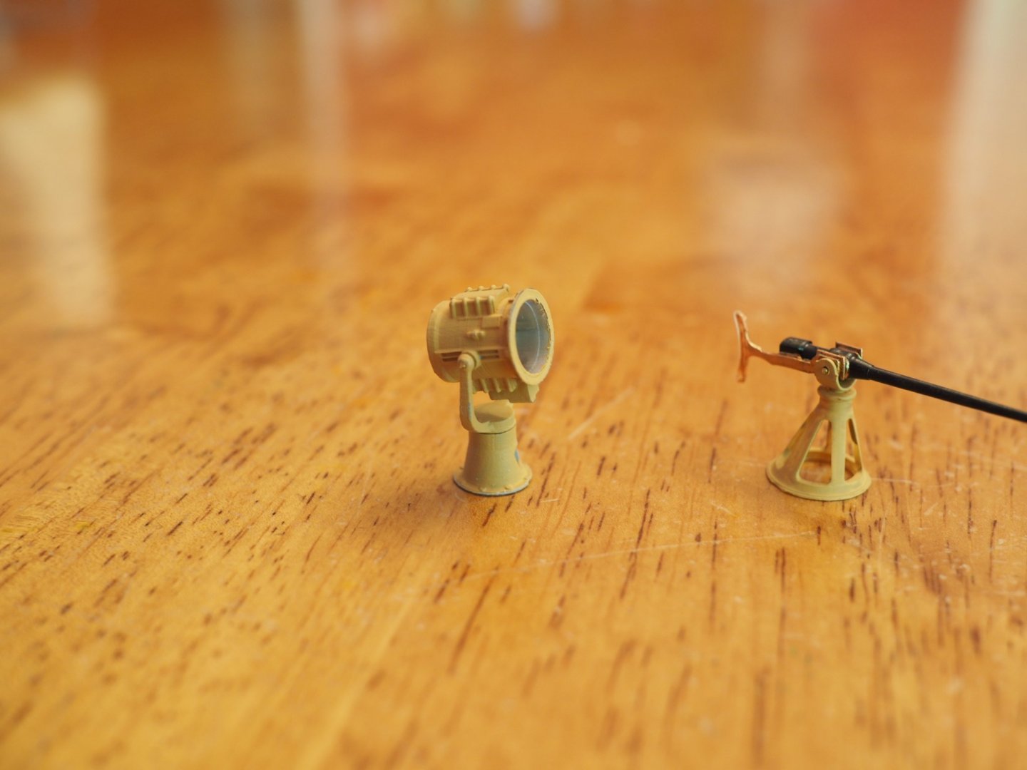
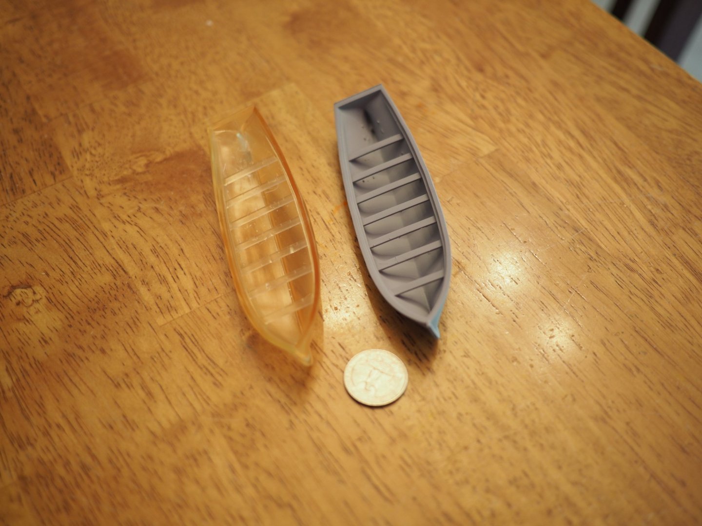
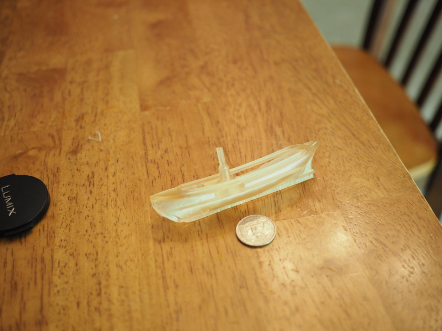
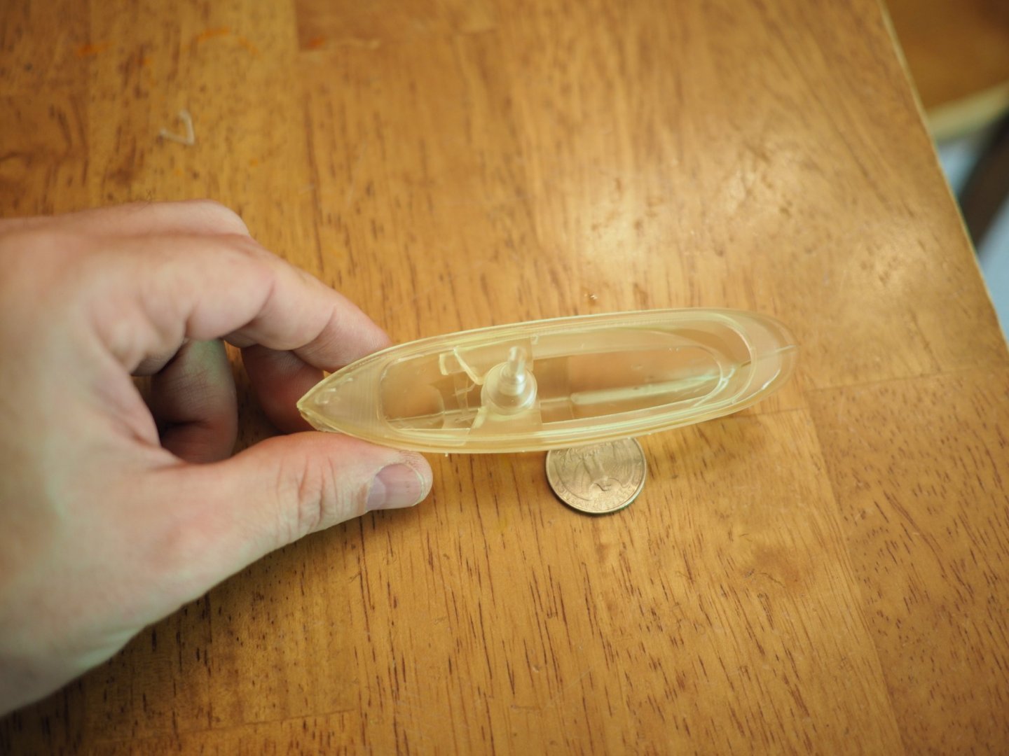
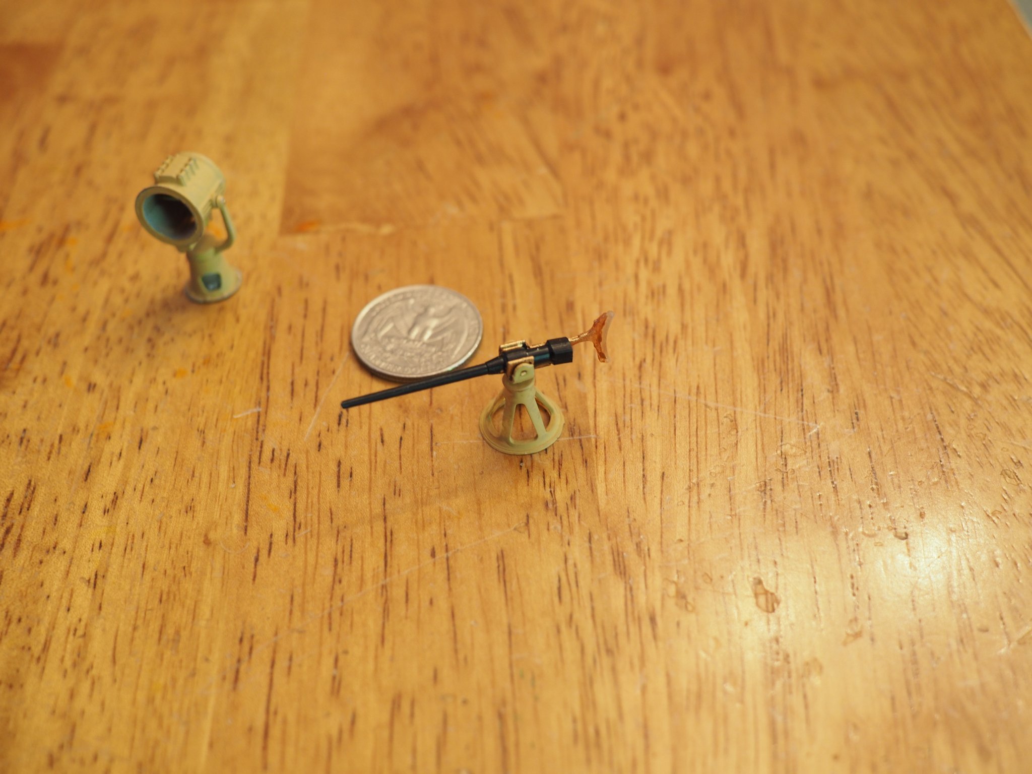
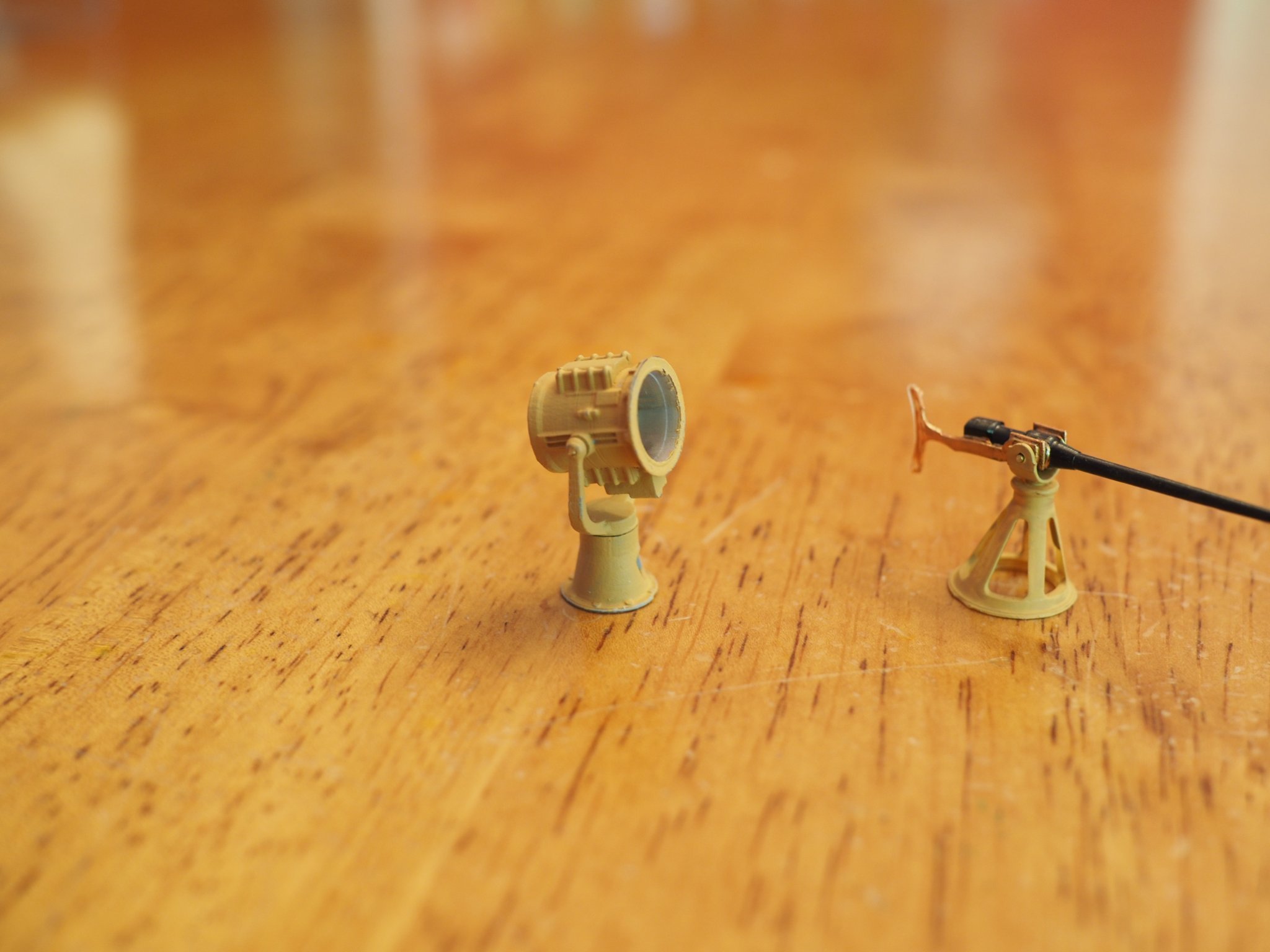
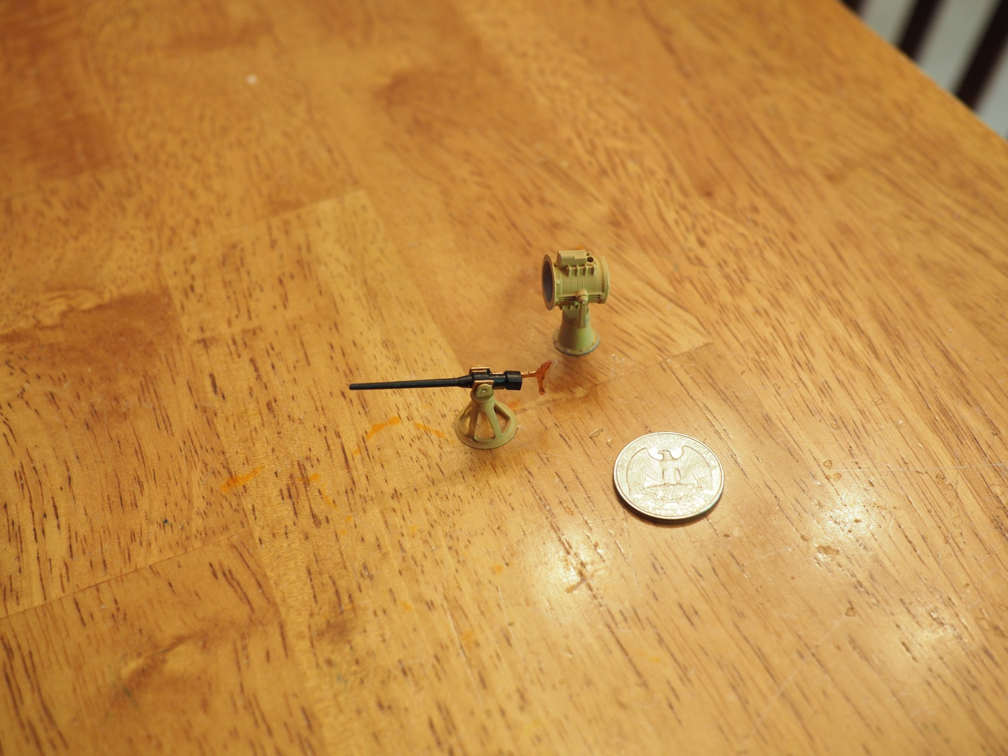
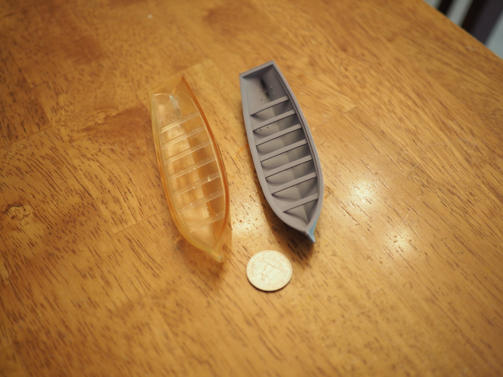
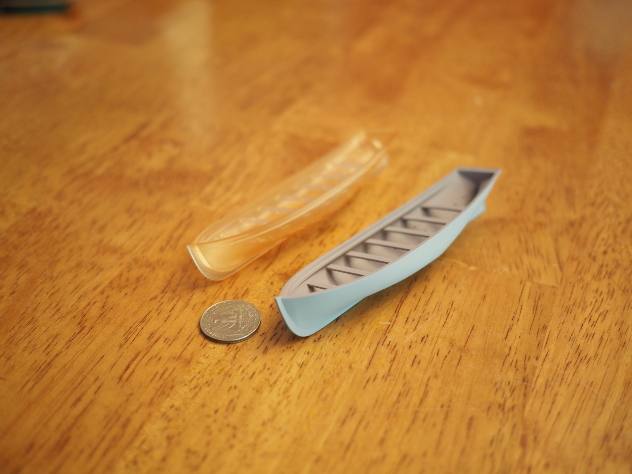
I figured I should start posting some updates and I have been making progress on the USS Maine - most recently I have been attending to small details like the small caliber (calibre) weapons and launches, cutters, and other deck furniture using a resin printer. here's some photos: This one is a 32ft Launch - doesn't actually go on the USS main but I have a 33ft cutter in the design stage that's pretty similar: Then there's searchlight and Driggs-Schroeder 6lb guns (yes they both pivot and swivel) unfortunately I have the searchlight rotated upside down in this shot: And I'm working on a 27' steam cutter that will go on the Maine - this print actually failed due to operator error (I didn't tighten down a knob for the build plate): will try to post some more pics later today


-
Hi Alan, I think this would be a good thing to consider - it uses a BL Touch probe which is what I use and it is reliable. It can be used to do two things: a) probe the corners of the bed to help you level the build plate b) "bed compensation" for the contours of the bed if it's not completly flat - or, if it's not truly level it will adjust the z-axis movement up or down to keep the distance of the nozzle from the bed uniform across the print. Technically 'bed leveling' involves the printer making adjustments automatically based on the probe measurements but I have one printer that does bed compensation and another that does automatic bed-leveling and they both work just fine. lastly, occasionally when a print of my has failed I've broken a few of the plastic probe needles but you can buy replacements for them (instead of buying a whole new probe unit) - I bought a total of 4 BL-touch probes before I figured that out I could just by the probe needle and replace it %$&#^&$)%*!!!!!!
- 460 replies
-
- 5
-

-
- Finished
- Flower-class
- (and 1 more)
-
There is an option to 3d print stanchions - but it would require something like a printer that uses ultra-violet curing resin - and you'd need to select resin that is more durable than what's typically used (most UV curable resin tends to be on the brittle side). I've not tried this but my gut tells me it's not a good option but then again I haven't tested anything.
- 321 replies
-
- 5
-
-
- Finished
- Flower-class
- (and 1 more)
-
Hi Yves, I tried a lot of different things, some were combinations (my 12 y.o. daughter helped me by applying each to test hull sections and charging me for it too!) but what seemed to work best for a single type of coating was Gesso (it’s also non toxic which is nice). Be careful though, thick layers of gesso take a long time to cure and can be a nightmare to sand down if not fully cured. A thick layer or glob of gesso can remain uncured for months and has to be peeled or cut off. Gesso applied in temperatures below 70f can take much longer to cure I typically sand down the hull by hand or with a small orbital but that’s not necessary if you apply multiple light coats and sand in between. I’ve started experimenting with some spray on options as well. I’d recommend you print out a hull section and test how the gesso works for you. Another option is to use uv curing resin - I’ve not tried that but should be viable in some circumstances depending on the resin properties.
- 132 replies
-
- 5
-
-
- charles martel
- battleship
- (and 1 more)
-
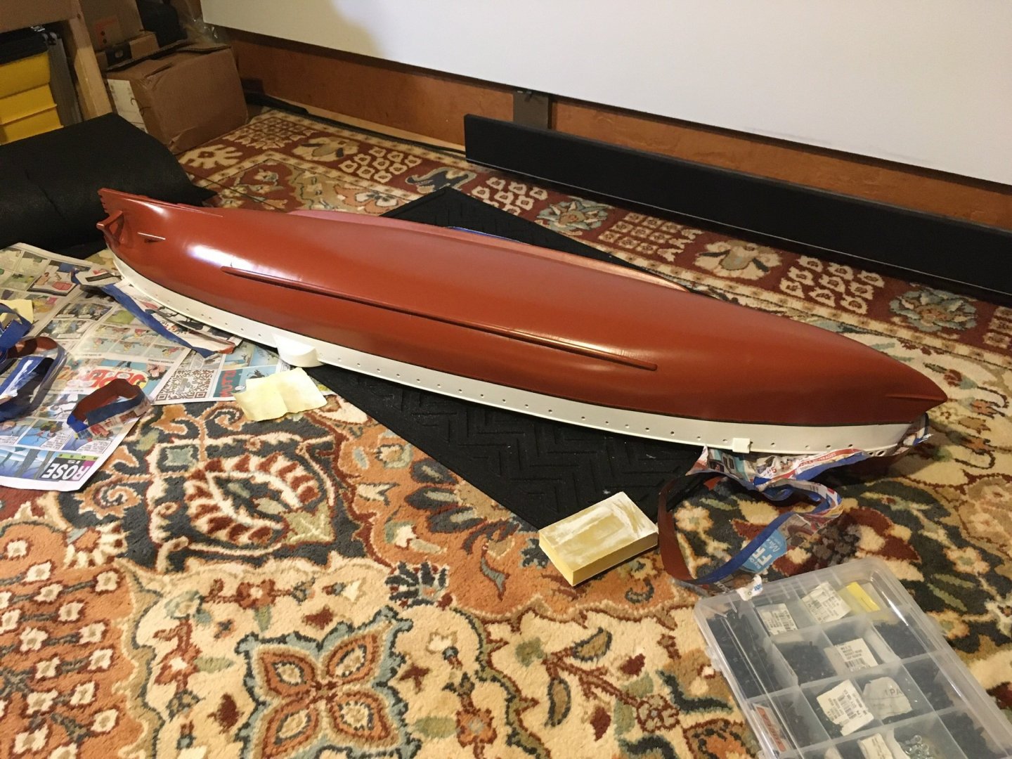
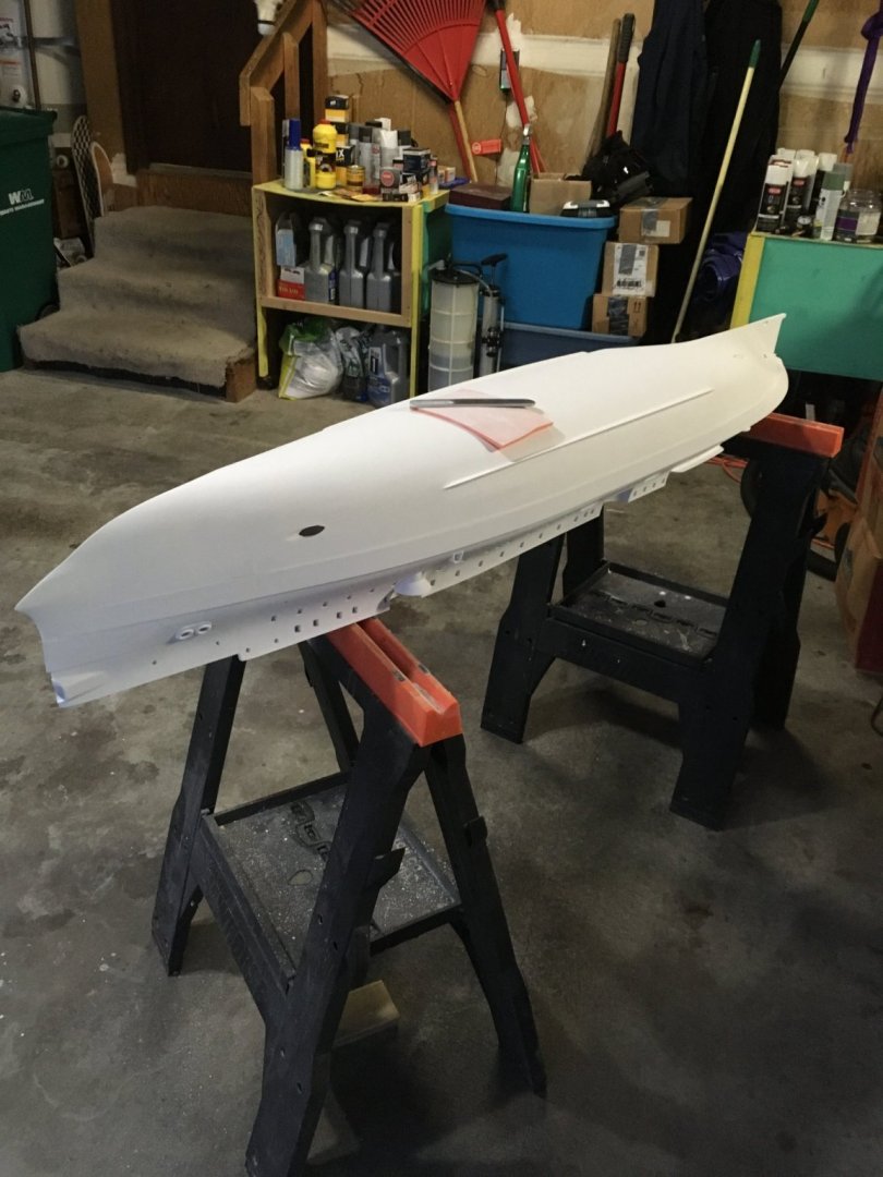
I’ll be floating the first one pretty soon ((USS Maine). Just a photo of the painted hull attached but will have to update the thread on that build when I get back from vacation,
- 132 replies
-
- 10
-
-
- charles martel
- battleship
- (and 1 more)
-
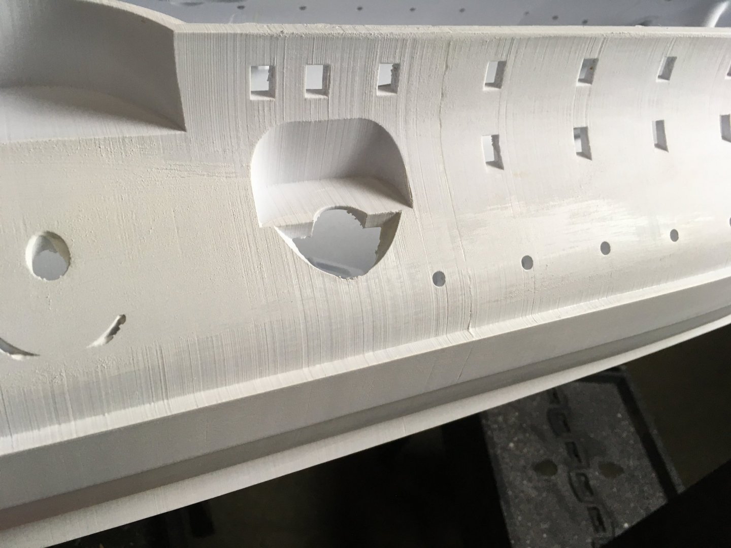
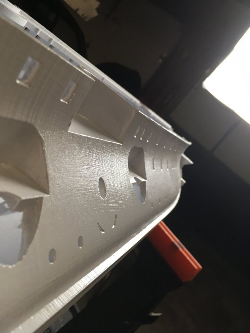
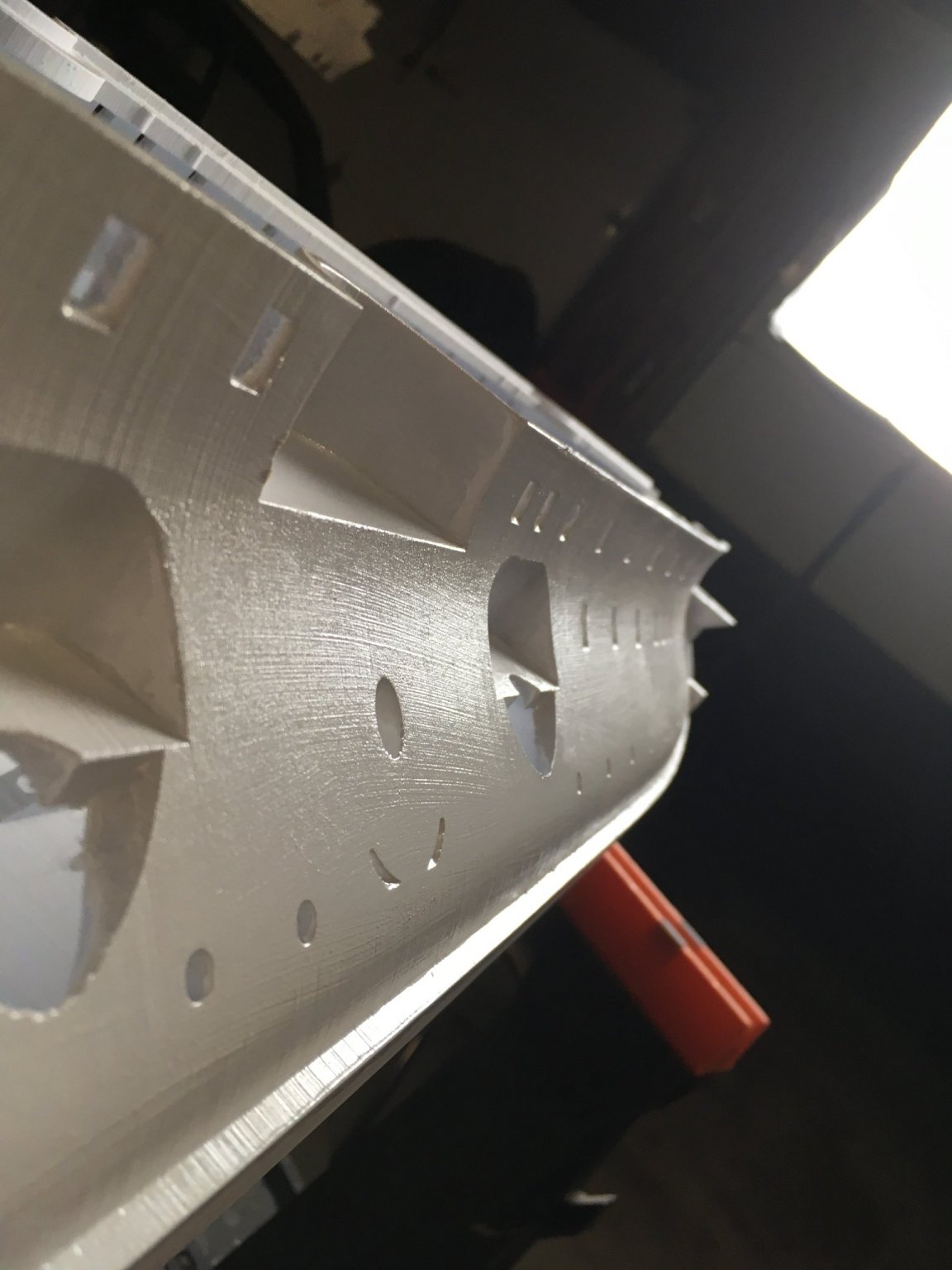
Small update here as I'm getting the hull ready for painting - mostly just some sanding and filling in the layer lines to get as smooth as a surface as possible - maybe a little filler in a few areas will be needed. another week or two and I should have the hull painted - one hiccup is the hull colour below the waterline - which was likely Schweinfurt green (also known as "Paris green") which was basically paint with a combination of copper and arsenic - it also have variations in the actual color but what's easily available to me at the moment is a green with a brown tinge to it, might still work for my purposes but we'll see- above the waterline I'm going to attempt to create the "lamp black" for the hull (which is a 'softer' black and not as harsh as the oxide black..so I think mixing in some brown will get the color in the right direction with some experimentation). Above the deck will be a light buff (much lighter than the typical US Navy buff... maybe more like the white star lines buff) humm colors are hard! here's a few pics of the getting the hull ready for painting - getting rid of layer lines with a combination of sanding and some readily and commercially available coating that will get sanded down makes work fairly quick. The flexible sanding pad (first image) works better then a "sanding sponge" as I can use my fingers to press into areas in a way that matches the exact shape of the proper contour. If you look at "image 2" and compare it to "image 3" that show how the how the layer lines actually are filled in (coating is translucent so in 'image 2' you can see layer lines under the surface of the coating).
.thumb.jpeg.0a3d5cd570178cf5899e85a511f0f992.jpeg)
- 132 replies
-
- 8
-

-
-
- charles martel
- battleship
- (and 1 more)
-
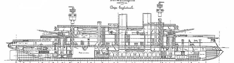
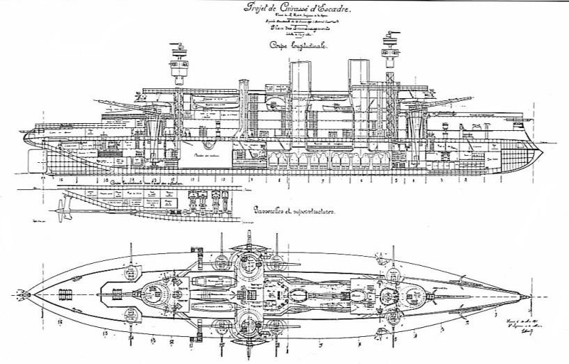
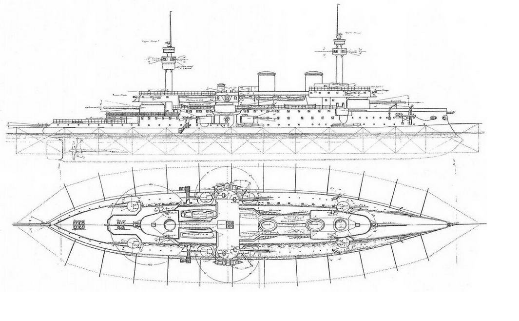
Hello sms_koenig_wilhelm sorry I didn't see your message until now - there's two books that would help: ISBN 978-5-98830-060-8 (it's in russian) but if you seach the internet you can probably find an on-line copy of it ISBN-10 : 2374680231 / ISBN-13 : 978-2374680231 - this one is in French and is also helpful The drawings that I have found on the internet are pretty scant on details and there's a lot that are preliminary designs so you have to be careful and check the drawings across as many actual photographs as you can get on the Charles Martel. I Found that None of the designs actually match what was eventually built but there was enough there to get the envelop of the ship and selectively taking specific features from one drawing that were accurate and combining it with features from another drawing that has additional parts that are accurate (all along the way verifying against photographs). Also There were changes to the design as the ship was built so I doubt there were any final "as built" plans.... if you compare these two drawings to the photo you can see there's notable differences across the board
.thumb.jpg.5e81e02b869380e520b01f9a0bf79199.jpg)
- 132 replies
-
- 8
-
-
- charles martel
- battleship
- (and 1 more)
-
Welcome Bruce! I'm certain you'll find that MSW is great place to discuss work on projects and it's a trove of useful information. There are many great members here that are very supportive and have suggestions and advice on a wide range of topics. You're going to have a lot of fun!!
-
Ah yes - MICRO KRISTAL KLEAR - I haven't tried that yet but now have some on order, it's water proof when dry so should be suitable for models that go on the water.
- 321 replies
-
- 6
-
-
- Finished
- Flower-class
- (and 1 more)
-
The work you're doing on that ship really looks good yvesvidal. What are you planning to do in terms of the portholes? I think the corvette in this scale has a lot of freeboard but they could let in water in rough conditions. One thing that I haven't done enough testing on is heat susceptibility for painted 3d printed ships - the glass transition temperature (when it starts getting soft) for regular PLA is ~between 55 to 60 °C (essentially above 131f) and for PLA+ 60 °C ~140f.... I've had two bare hull sections (white PLA+) outside for 12 months and they are fine, but I'm up in the pacific northwest and the sun is not that intense - what I worry about small thin/fragile gun barrels painted black and drooping when exposed to high ambient air temp and direct sunlight. I don't think it's an issue in the northern latitudes - but I have to try out a few things and see how they do. I would suspect that hull painted black, in the back seat of a parked car on a hot day with the sun hitting it for 6 hours will exhibit some effects from the heat.
- 321 replies
-
- 7
-
-
- Finished
- Flower-class
- (and 1 more)
-
Quite a nice build and looks like a fun one at that! On joining hull sections together I've had limited success with using a solvent based plastic welding agent. I dropped one of my 3d printed ships (sections had been joined with a plastic welding agent) from a height of about 3ft on to a concrete floor and there was some separation but the weight of that ship was over 5kg empty (I use epoxy now by the way) but I doubt MEK joined hull sections of the 1/48 flower corvette will have issues (still best not to drop it!). There's a lot of things you can do with designing a boat for 3d printing, if you can imagine it, you can probably do it.
- 321 replies
-
- 6
-
-
- Finished
- Flower-class
- (and 1 more)
-
Well that's great news - Autodesk must have caved to the community pressure, I remember it was late last year that they announced that the free versions would no longer support export to STEP or STL so good to hear they did the smart thing!!!
-
It’s still possible to get fusion 360 for free but the free version no longer allows export to the STL file format (which is what you would need for 3D printing). An EAA membership is $75 I think and you get solid works for 12 months… that might be a good option.
-
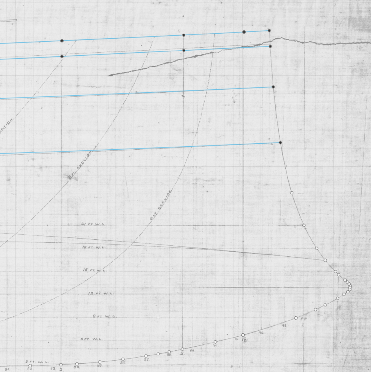
Picking up where I left off, I've created a construction plane at the station which is nearest to the middle of the ship using the "plane at an angle" and specifying 90° for the angle so I can look from bow to stern and sketch and size the canvas for the station lines. I've trimmed the image already and inserted it as a canvas on that plane & I've also dropped vertical lines down on either side (using project to pick up the edges of the rectangle that I created in the beginning which represent the max beam of the ship: Looking straight down the the center now - there's a couple of things I noticed - The scanned image of the hull shape shows some very slight skewing which really isn't unusual or a problem but the horizontal lines that I drew to see if I could intersect the position of the three rails is off by about a millimeter or so. Not a bid deal - and usually you have to decide what is going to be the authority when there's some discrepancies, especially when you might be using drawings from different sources. In this case I'll be using the drawing of the side profile as the authority since the differences are really small and it's typically easier to compensate the hull shape lines to meet the requirements of the side profile. but if the difference is large the drawings of the hull shape should control. I've got red circles where the horizontal lines should be intersection of the bearth deck, gun deck, and underside of rail to the outside hull line - I'll actually be using multiple horizontal lines to create points at every station to make rails that follow the shape of the hull from the bow all the way to the stern which will help maintain a smooth surface and more accurate hull shape.


-
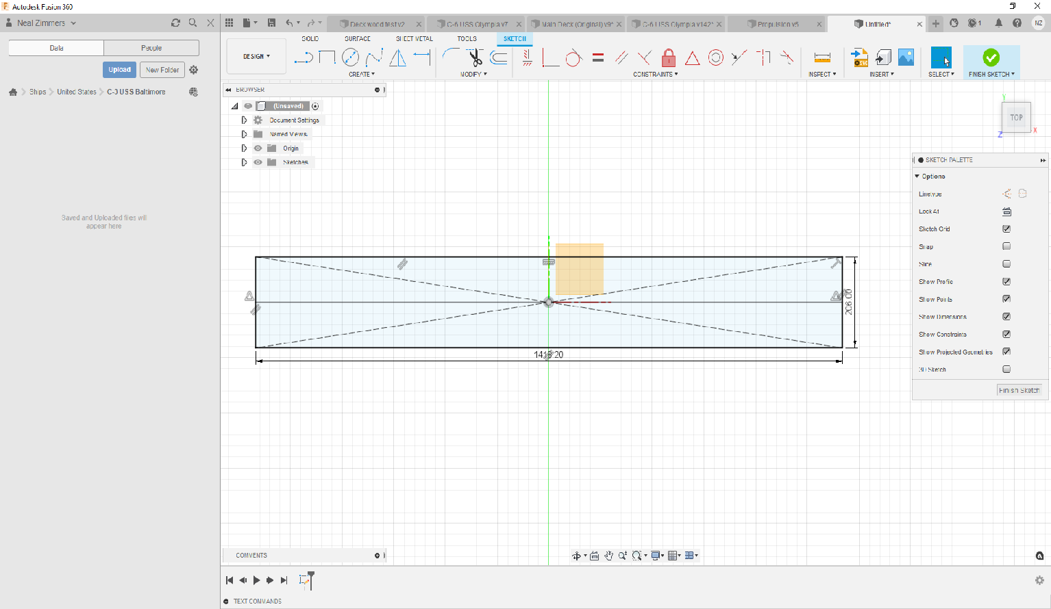
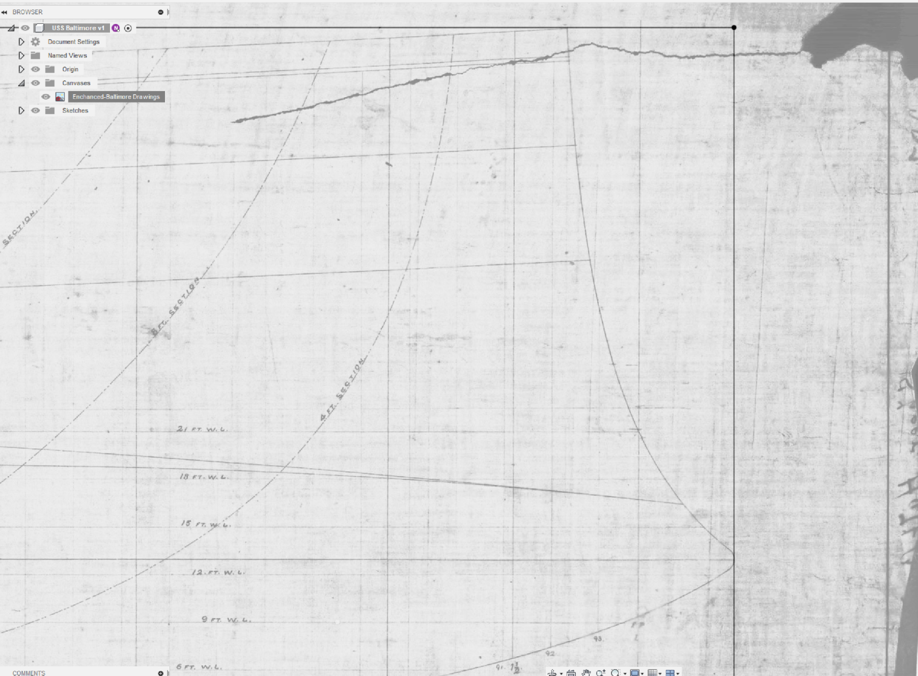
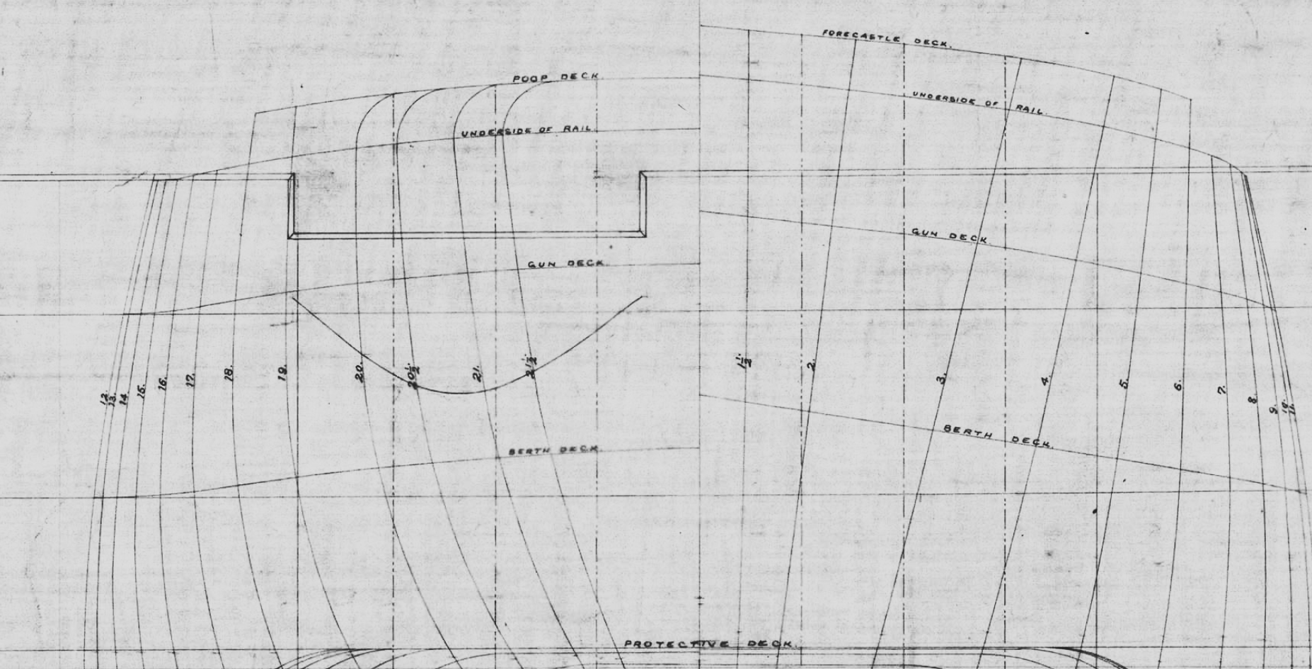
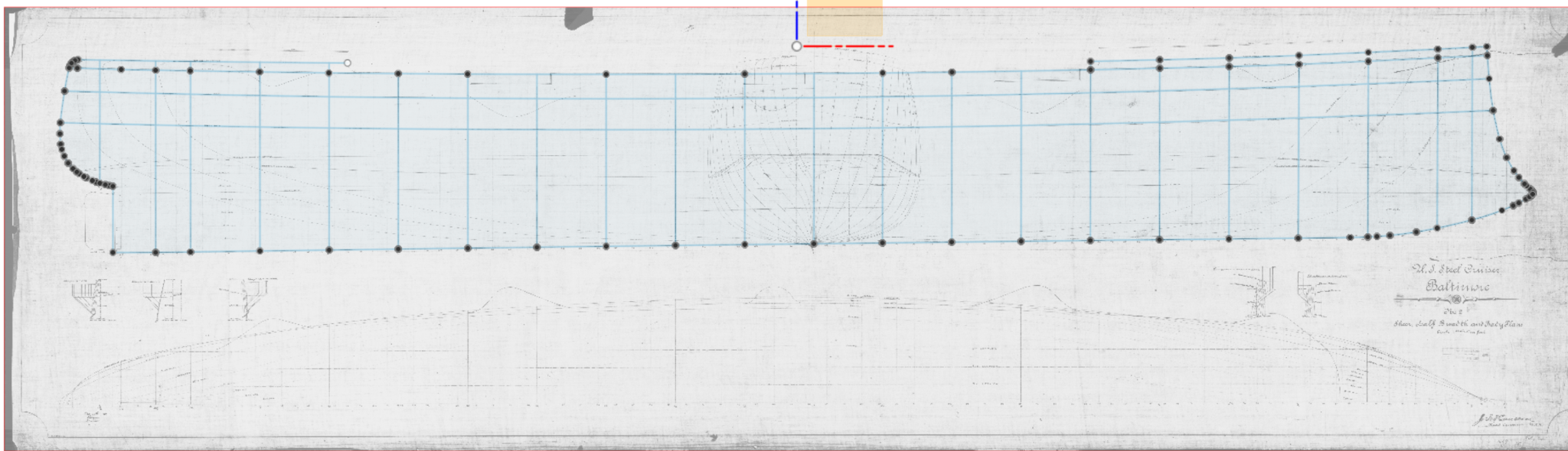
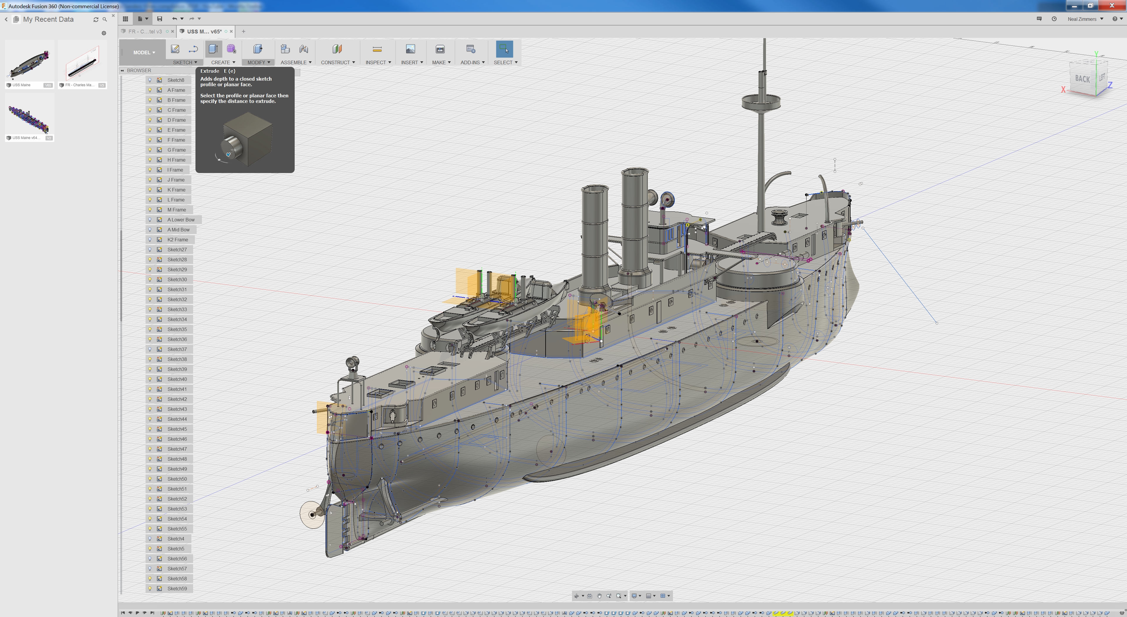
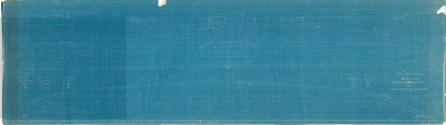
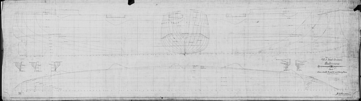
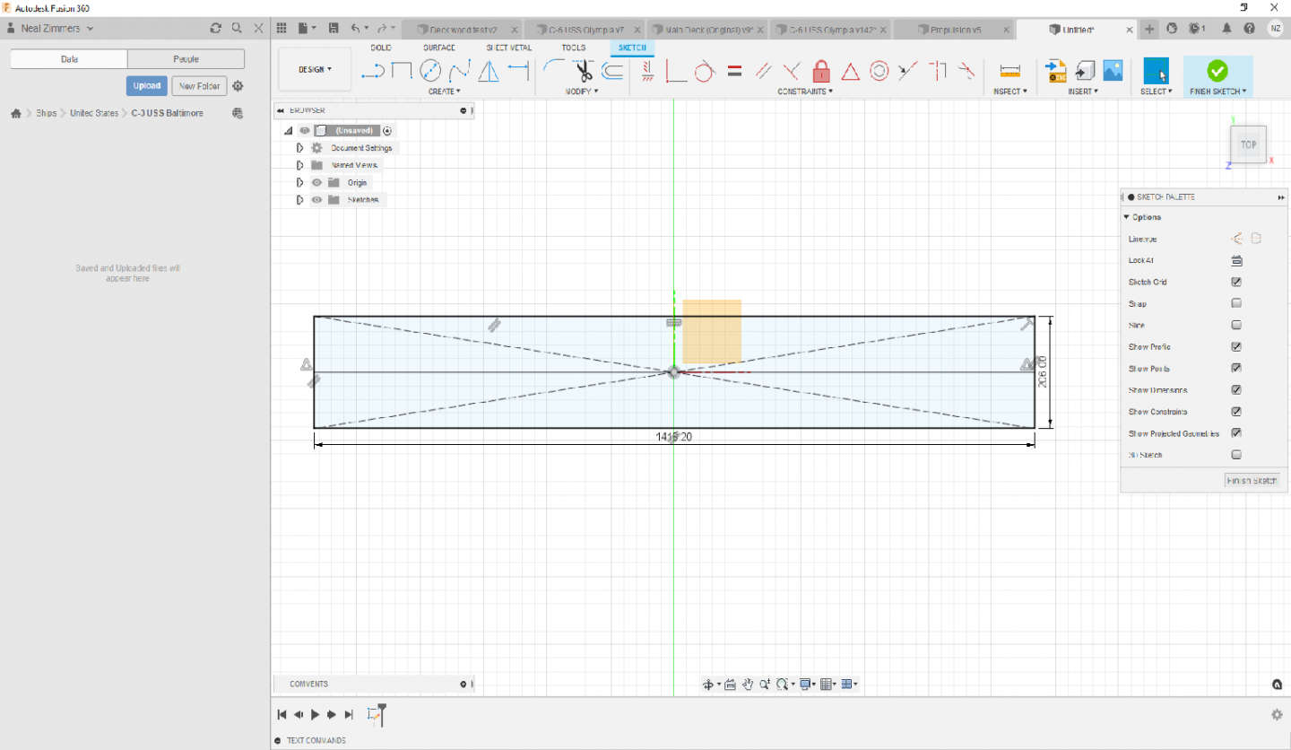
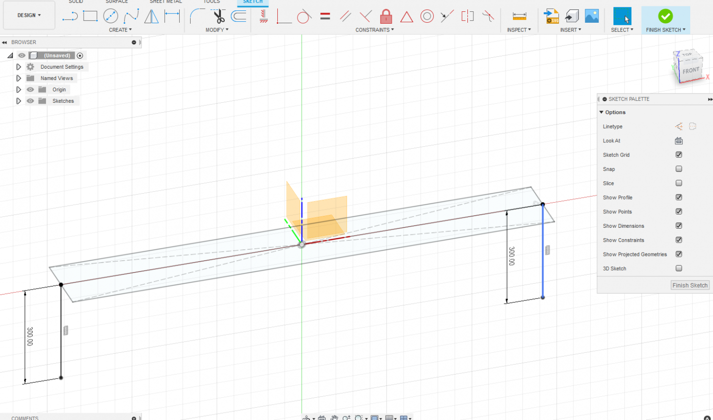
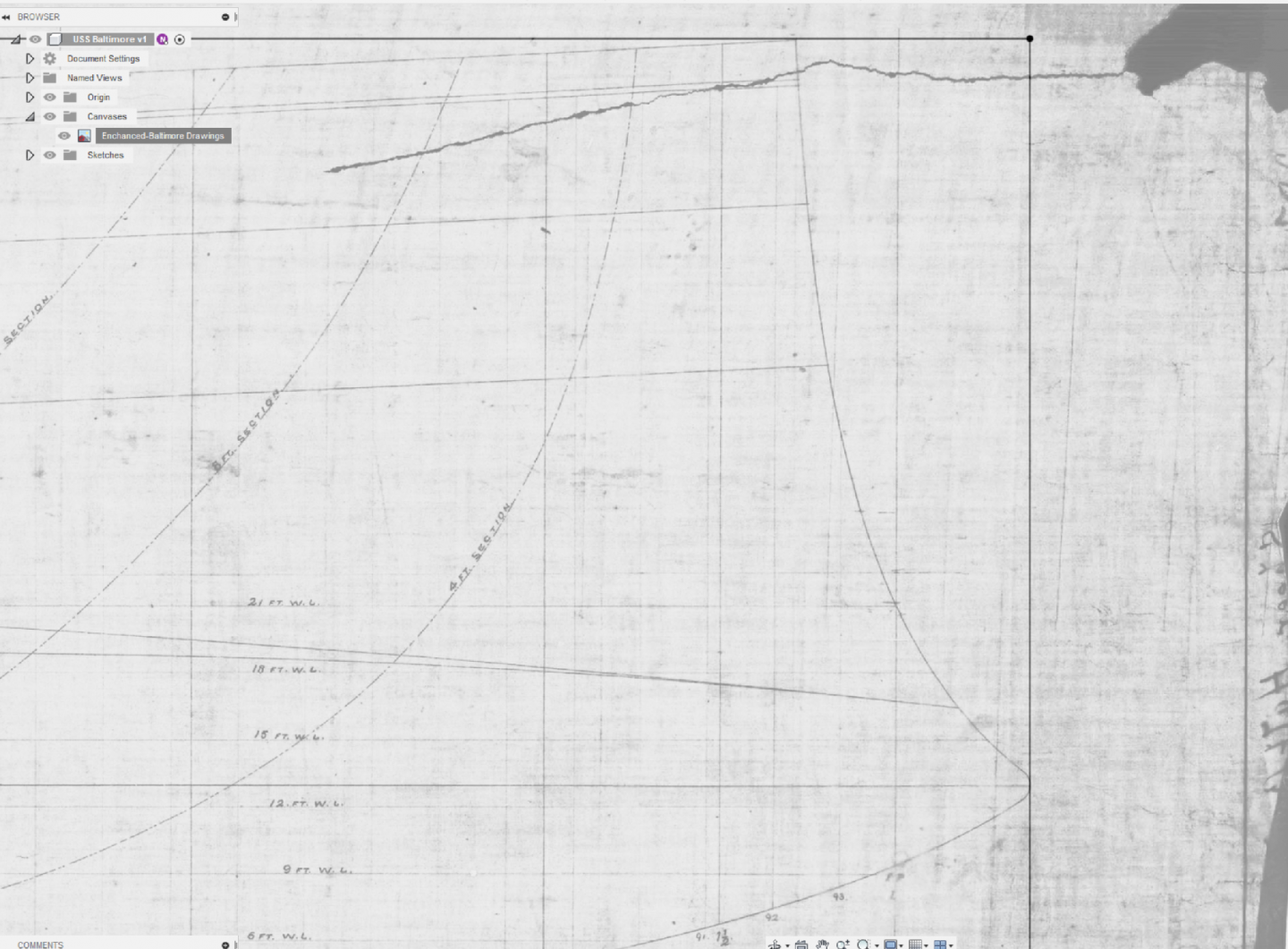
I'm going to be starting the USS Baltimore (C-3) so I thought I'd create a thread where I can share some techniques on using Fusion 360 for creating a model of a ship and the design considerations for 3D printing that I've developed over a couple years as I progress through the design.... The Baltimore is a nice mix of areas that are easy and some harder spots so it's a good example to use. It's also a pretty historic ship - built domestically in the US using plans bought from Armstrong-Witworth. Baltimore was an improvement on it's predecessor (USS Charleston). It was laid down in 1887 and was one of the first US Navy ships with the more powerful and efficient, and at the same time it did away completely with sails which were still often provisioned on other ships of it's time. The Baltimore was one of the ships involved in a diplomatic crisis between the US and Chile during the Chilean civil war. During the Spanish American war Baltimore was second in line behind USS Olympia during the Battle of Manila Bay. As a side note it seems the plans for the Baltimore were originally drafted by Armstrong for bid on work for the Spanish Navy who eventually turned down Armstrong's design in favor of one from JG Thompson - who produced a ship for Spain which was christened the "Reina Regente" which tragically sunk with all 420 hands after 7 years in service..... Here's a few details of the USS Baltimore: Length: ~336ft Beam: ~48.5ft Screws: 2 Speed: 19knts Main Armament: Four 8" guns Secondary Armament: Six 6" guns Type: Protected Cruiser First thing I do gather as much information on the ship – photos are of great importance since a lot of the detail areas of the ship you won’t find in drawings that are available. I was lucky enough to find a series of drawings that included the hull lines on the Baltimore in either the library of Congress of the National Archives (I can’t remember which – since I grabbed them about 2 years ago). I also downloaded every photo I could find from the Navy History and Heritage archives which is a good supplement to the library of Congress and the National Archives. The plans that were available were old blueprints – actually blue! And the lines for the hull were hard to discern so I converted the images to black and white and tweaked the hue and contrast so it was a little easier to see things: Original Cleaned up: Before I go any further, I want to mention that for creating ships in Fusion360 I use the metric system since the 3D printer that I use is basically a metric system machine with movements in fractions of millimeters and a nozzle size of 0.4mm so that particular dimension (0.4mm) is somewhat of a constraint in the design process (i.e. I cannot print something that's only 0.2mm wide) The next step is converting the ship measurements into millimeters (length and width) and creating a box in fusion that I'll use to start designing the hull, but before I actually do that I'm usually checking multiple sources and, not surprisingly, I got different from different sources and usually no clear definition of what the measurement actually is (i.e waterline length, parallel to parallel, or length overall). Since two sources (one of which was the "Dictionary of American Naval Fighting Ships" published by the Department of the Navy) concurred that the length was 335' and beam of 48'8" that is what I'm going with. After conversion to millimeters at 1/72 scale it comes out to 1418.2mm long and 206.0mm wide....so now I draw that box in fusion 360 on the X plane in Design/sketch mode using a "center rectangle" on the origin and put a line down the middle lengthwise Next I switch to the Z plane and use the "p" key to project a point on both ends. I use these points to draw vertical datum lines that will be used to define the aft and foremost ends of the hull: These lines help a lot when sizing and centering images that you want to trace. This is where things will get a little tricky - so were going to start with a side view of the ship and insert it into the design and scale it up and down it until the ends of the bow and stern are just touching the vertical datum lines and the highest point of the bow is touching that middle line that runs down the center of the rectangle. (To insert, position, rotate, and size an image on a plane in fusion 360 you would used the "insert canvas" while in the "Design Mode"). So I've done that and have it zoomed in to show the bow position: From here, we're going to do a couple of different things. Firstly, you'll want to look and the hull profile lines and write down the station numbers because you'll be needing those later! On the Baltimore there's 23 unique station numbers (going from 1.5 to 21.5) as below: Next is where it starts to get fun (maybe...) - were going to trace the side profile of the hull using the design/sketch mode in Fusion 360. An in the case of the Baltimore we'll draft a line along the all the rails and decks (which you can see named in the picture above) even if they are incomplete. We also need to draw the vertical lines for the stations of the hull profiles. One mistake I use to struggle with was using a straight spline when tracing curved features of the hull, especially the bow. Splines by themselves can work but once you complete a spline it becomes harder to correct. These days I use "sketch points" and draw splines from sketchpoint to sketchpoint, and its a bit easier to make adjustments if I didn't quite get things right. Here's close of up some sketchpoints (in white) I'm using to define the bow: defining And here's where I am basically ready to move on to the next step and add the lines that define the shape of the hull (which I'll be using the vertical lines to do):


- 18 replies
-
- 10
-
-
Welcome Tim! I agree with others - the toothpick, scrap wood, and thread model in your photos is really good - because it was fashioned by hand from just basic materials available it has distinct presence and real magnetism! And a very warm welcome to you, you are in good company here!
-
Very nicely done indeed - congratulations!
-
Hi Jean Pierre, welcome! I do quite a bit of CAD myself but I use Autodesk Fusion 360 - it's available for free for hobbyist but I don't think you can export to other formats like STL or IGES with the free version - to export to other formats you need to pay a subscription.
-
Condocert is a good one, I think the French pre & semi dreadnaughts extremely visually interesting.
-
thought I would share what's I'm attempting - I'm using fusion 360 to create the basic shape / profile and then port that into blender to shaping... I have no idea if this will actually work though!

-
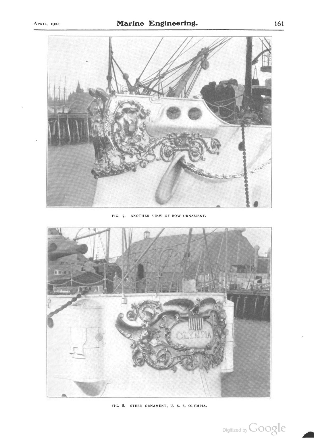
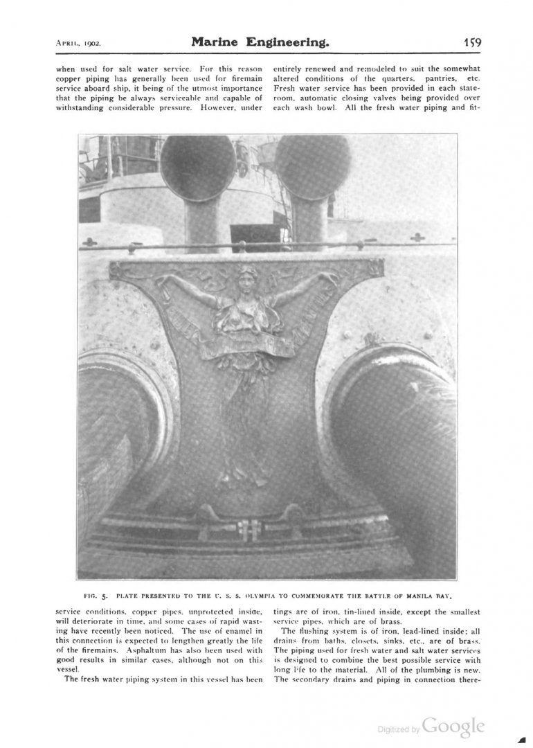
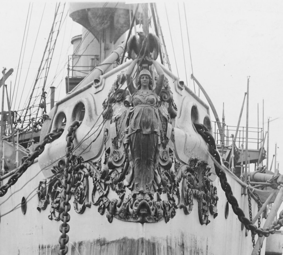
Hi Ron, Yes indeed the figurehead and the stern plaque were likely added in 1901 during a minor refit - Marine engineering from April 1902 reported on the changes of some of that refit included photos of the bow ornament, stern ornament, and a flat plate with a relief that commemorated the battle of manila bay.

-
Hi Lou, I do have that one and a few others for the Olympia - I know of about 5 bow ornaments/figureheads that have known public locations but whereabouts of all the rest (including the Olympia's) are unknown to me. A 3D scan would make quick work of the modeling - I am kind of assuming that many have been preserved somewhere (hopefully not in private hands). Since I'm very new to 3d sculpting it might take a really long time to develop the skill to do these but eventually I'll get there if that's what it comes to! The bow ornament from the USS New York (ACR-2) was actually at the Puget Sound Naval Shipyard Museum, Bremerton, back in the 50's, that's one I'm chasing down too. NH 85145.tiff
-
Unfortunately the Olympia as preserved does not have the figurehead otherwise I’d be there in a heartbeat!
-
So, I'm currently modeling the USS Olympia and for awhile I've been thinking about how to model the figure heads on some of these old ships - I have a resin printer that would use for the actual printing - but as far as creating a model I don't think what I usually use (Fusion 360) is really the best tool - maybe blender is the best option? (have never tried it). The figure head of the Olympia was some sort of forging - it's possible that's it's still around and ideally I'd like to 3d scan the entire thing but it might take a long time to track down! Anyone have any suggestions?


.jpeg.8cda1c4d37b3c7ce99f89a4f34e418ff.jpeg)

.jpg.bf761efd6fa0052d9b0fbb7e800b7efe.jpg)