


shipmodel
-
Posts
936 -
Joined
-
Last visited
Reputation Activity
-

 shipmodel got a reaction from aviaamator in Queen Anne's Revenge 1710 by shipmodel - FINISHED - 1/36 scale
Hi all –
Here is the latest installment of the build log. No pirate talk, just building - - -
Some work has been done on the hulls since the last build log, but not enough to show. Instead, the next of the independent subassemblies was completed. These are the anchors.
Queen Anne’s Revenge carried four anchors of different sizes, all of which have been discovered. They range from the largest, with a shank length of 13 foot 7 inch and a weight of 3,141 pounds to the smallest at only 8 feet and 642 pounds. The others had shank lengths of 13 foot and 11 foot 4 inches. Here is the archeological drawing of one of them.
Image 1
Budriot has drawings of several sizes of anchor for Le Mercure, but the drawings are all identical other than size, and none quite fit the ones discovered. I took his drawing and sized it up or down in Photoshop to make drawings that fit the sizes needed.
Image 2
An anchor is a fairly simple construct, with only a few parts: the shank with its arms and the flukes pinned to the arms; the wooden crosspiece called the stock, and a metal ring through the shank above the crosspiece. Here they all are for a pair of 11 foot anchors.
Image 3
You can see that they are in various stages of completion. The wood used here is pear, throughout. I did not cast the shank/arms because there were 4 pair of different sizes rather than 8 of the same size. It would have taken longer to make 4 masters and then cast them.
The first piece to be shaped is the shank. A piece of pear was cut on the Preac saw to a square cross section of the appropriate size and then cut to length. The drawings show that it had a square head where it went through the crosspiece, then became round below the head, which widened and returned to square with rounded corners where it mated with the arm for the flukes at the throat. A round tenon at the foot was secured through a hole in the arm piece.
I first milled the tenons on either end. This is easily done while the wood is still square. Here you can see the setup on the Preac. The miter guage is used to keep the wood square to the blade and the fence is used as a depth stop.
Image 4
The height of the blade is set by using an adjustable fitting that sits under the hinged blade holder. It is a screw in a wider sleeve with a red plastic cap on the end of the screw. The hole in the bottom of the sleeve conveniently fits around one of the bolt heads on the blade unit. It is a cumbersome and fiddly arrangement, but I am used to it after 20 years.
Image 5
To cut the tenon I set the blade to the desired height, testing by making passes on a piece of scrap basswood. I first cut the shoulders of the tenon, then nibbled away the rest of the wood using a wide blade. The final pass is always sideways across the top of the blade to smooth the side of the tenon.
Image 6
The final result is a perfectly centered and square tenon on each end of the shank blank. The tenon that will go through the fluke arm piece is narrower than the head tenon and will later be rounded by trimming the corners then twisting it through progressively smaller holes in a drill plate.
Image 6a
With the head tenon cut the square hole in the wooden crosspiece has to be cut to match. This is possible because the stock is built up from two pieces. Again using the Preac the blade was adjusted till the cut was exactly half the depth of the tenon. I tested this by cutting grooves in two pieces of scrap that when mated allowed the tenon to fit smoothly but not too tightly. You can see this in the upper part of the photo. Below it is the first side of the stock with the tenon fit into the channel that was milled out.
Image 7
And here you can see how the two stock pieces fit together around the tenon.
Image 8
With the channels cut the side of one of the stock pieces is colored with black ink and the pieces are glued together and clamped using one of the shank pieces to locate and match the pieces.
Image 9
After the glued dried the drawing of the stock was cut from a printout of the sized drawing. I used Scotch Spray Mount to temporarily attach it to the stock blank. With the blank still having a square face the holes were drilled for the treenails and bolts that were used to hold the two halves of the stock together. (You may notice that this piece does not have a square hole for the shank. I forgot to take a photo during construction, so this is a scrap piece made up later for the log).
Image 10
The stock was cut close to its profile on the band saw and then smoothed using a sanding drum in the drill press since I do not have a spindle sander.
Image 11
The rest of the construction is pretty straightforward. Going back to the photo of the pieces, you can see that the sides of the stock were tapered as shown on the drawings and the treenails inserted and sanded smooth. The shank was fitted to the arm piece and both were smoothed to shape and to fit together at the throat. This was done with the tenon just friction fit in the arm piece.
image 3 repeat
Once the throat joint was smooth the arm was removed and a step was cut into it for the heel of the fluke. The flukes were cut from 0.025” thick brass sheet, ground to final shape, and then peened to a shallow dish form. They were fitted to the arms and pinned through using iron wire which was clipped short and peened on both ends to rivet the fluke to the arm.
Image 12
The stock was given its four iron strapping bands and a coat of stain. The final wood selected for the stock was beech, which looks remarkably like oak in this scale. The shank was painted matte black and was fitted to the stock. The six bolts at the center of the stock were made from iron wire cut a little proud of the surface and filed smooth but not flat. The cut ends will age over time to a generic metallic look that will contrast with the look of the treenails. The ring is made from brass rod that was wound round a dowel, clipped and flattened, then chemically blackened. Here is the completed 13 foot pair.
Image 13
Until I built these anchors I had little idea how large they really were. Compared to my scale figure the 13 ½ foot anchor is massive, and even the 8 foot one would have been a handful. The entire set of four anchors weighed over 8,000 pounds.
Image 14
Image 15
I’m off to the NRG conference next week, so it may be a bit until my next posting. Until then, let me know if you have any questions about my methods and/or my madness . . .
Dan
-
 shipmodel got a reaction from CiscoH in Queen Anne's Revenge 1710 by shipmodel - FINISHED - 1/36 scale
Hi all –
Thanks for your comments and suggestions. I plan to incorporate them into the second iteration of the boat which will be built when the hardwood strips arrive from the supplier.
When we left the shipyard the hull of the boat had been fully planked with the shutter planks fitted on both sides. The hull had been marked out in pencil for the rib locations in preparation for the nails which would have fastened the planks to the ribs. Here you can see the lines for all of the ribs that sit square to the keel as well as for the two cant ribs, drawn on the port side of the hull.
For the fasteners I had to find a way to make them look right without devoting an excessive amount of time to the task. Since there are 11 planks on each side, 25 rib or transom/stem lines that the planks cross, and two fasteners per crossing, the math says that there have to be 1100 fasteners for the exterior of each boat. Add in some more for the interior work and you can see the magnitude of the problem.
The original boat probably had the planks nailed to the ribs, with the ends peened over to clinch them. I experimented with a plank/rib mockup and could never get the holes in the planks to come through the ribs in the proper places. Instead, I decided to drill the holes through only the planks and worry about indicating the nails on the inside of the ribs later.
I first drilled all the holes. Here you can see how there are two in each plank in an offset pattern. I used a 0.012” drill, which scales up to 1/2”, which would be about right.
At first I tried inserting pieces of annealed iron wire into the holes, clipping them short, painting them with glue, then filing the tops flush with the face of the planks. This was incredibly time consuming and fiddly. I then decided to try the technique of leaving the holes empty, sanding the planks to fill the holes with sawdust, then painting on a finish to hold in the sawdust. This looked good and I don’t believe that anyone can tell the difference with this short cut.
* * *
Aarrrgh, scalawag that ye are! Ye’ll not be taking any modern short cuts with me boats. I be Dread Pirate Peter, and I’ll have yer guts fer garters if ye dinna do a manly and proper piece of work.
No, no, it will be OK. Really it will. Here, this is what the nail holes look like after filling and staining. I have had several critical people, including my wife, compare them to the ones with the iron nails in them and no one could tell the difference. In fact, the slightly spread discoloration of the wood grain closely mimics the way old wood stains when a nail rusts into it.
* * *
Tis all very well and comely, but rest ye not on yer laurels, lest ye rest on yer ****. I be watching ye. . .
* * *
Soooo, with that out of the way, I turned to fitting out the interior. First the missing ribs were bent and fitted into the interior. These were the two cant ribs at the bow and the aftmost rib at Station 21 that had been left off to make planking easier.
The first interior piece to be installed was the tapered central plank of the flooring. It strengthens the keel and is the location for the lifting rings and mast step.
To each side the rest of the floor planks were installed. They are not tapered but fit against the tapered center plank due to the curvature of the hull. They are held in place while the glue dries by inexpensive hair clips from the cosmetics section of the drug store. They initially look like the one at the lower left, but are easily bent by hand to the shape in the lower right. This now allows them to reach around the hull to apply pressure at the tips.
Next to be installed are the sheets, the planked platforms at the bow and stern. They will appear in later photos, but I did not take pictures as they were being built. Construction is straightforward. Planks were glued to a pair of battens underneath to make a flat sheet larger than needed. A paper pattern is cut to fit the space and the wood sheet is cut to that shape. The edges are bevelled to match the curve of the hull and it is glued in place to the ribs.
Now the thwart stringers are installed. I first bent one piece of stripwood to shape and glued it in on the starboard side at the height indicated on the plans. The matching strip was bent and trimmed for the port side and held in place temporarily while I balanced pieces of stripwood across from side to side and set perpendicular to the keel. These are known in woodworking as ‘winding sticks’ although I don’t know why. Looking across their tops you can easily see any variation from side to side and any tipping compared to the centerline and the edge of the sheets. Once I was satisfied with the levels, the port stringer was glued in place.
The plans show square section wood pieces running side to side just under the thwart stringers near the bow and stern. They have a short section in the center that has a round cross section. I do not know what they were for, but perhaps the rounded section would have a halyard led around it when the sail was raised, sort of a non-turning sheave. Whatever they are they were shaped, fitted and glued in.
The lifting rings and mast step were located and attached to the central floor plank. I also drilled the nail holes for the floors and sheets as I did for the hull planks. My one regret is that I did not do this for the ribs at this point when they were exposed. It turned out to be too crowded later – a detail that will be corrected on the next boats.
The thwarts were cut from 1mm thick stock, with the middle one being wider in the center and having added knees. It holds and supports the metalwork that acts as the mast partner. This fitting is made from brass strip which is chemically blackened, then glued and pinned with wire nails to the edge of the thwart. A decorative beading was scribed into the edges of the thwarts, then they were installed on top of the stringers with spacers between them.
Unfortunately, once the thwarts were installed it was clear that they were sitting too high in the boat. No rowers could have sat on them and had their feet reach the floor for leverage. Here the flexibility of the Lineco glue came to my rescue. With the tip of a #10 blade I was able to pry up the thwarts from the stringers and then remove the stringers without any damage to the hull or ribs.
The stringers were lowered 6 scale inches and reinstalled, followed by the thwarts, which looked much better after the adjustment. I went back to the plans and determined that the problem was there and not in my measuring or building. Just one of those problems that had to be built to be discovered.
Fitting out the rest of the interior is self-explanatory. Working up from the thwarts the stern seats were planked up over battens. They sit on top of the thwart stringers and the aftmost thwart. The foremost thwart has a pair of knees set on top.
Square section stringers were fitted and glued to the inner sides of the sheer strake so their tops matched, and were strengthened at the bow by a breasthook and at the stern by two transom knees. Thole blocks were set on top of the sheer strakes and stringers and will be drilled for the thole pins to be added later. The locations of several of these had to be adjusted from the plans, which did not have them at a consistent distance from the associated thwart.
The only difficult woodworking came at the bow where the curved and carved fairleads on either side of the stem were joined with a double-dovetailed cross-support.
With the boat all but complete the rudder was fashioned to match the plans. Two planks were fitted and tapered, then cut to the proper profile. The pintle straps were made from brass strip, pinned through with iron wire and chemically blackened. The tiller is brass bar that was tapered and blackened, with an epoxy bulb at its tip.
Top and bottom gudgeons were fashioned from blackened brass strip. The upper one simply slipped into a hole drilled into the aft face of the sternpost, while the lower one had to be bent in several directions before being pinned against the sides of the sternpost. It only remained for the thole pins to be installed and the boat was complete.
* * *
So ye think ye be quite clever, do ye? Quite the boat builder? I be the judge of that. I also bring me great-great-great grandson Peter who says he has worked with ye before. He be a great galoot of a puppy, but he be useful to judge yer work. He set up this temporary mast and I grant ye that said boat be mightily even side to side.
He sits well in the stern and nothing pulls my eye to say that he could not reach and steer the tiller, should he take it into his head to do some work, the lazy lout that he be.
It shivers me innards to grudge ye my approval, but i’ faith I canna find much to dislike. But be warned that I will no be put off with such minor success. Ye must do as well or better, or feel me wrath fall upon ye like to the Trump of Doom.
Well, there you have it. The second boat will be made from hardwoods now that most of the construction problems have been identified, although I am sure that new ones will appear and demand solutions. Those may be harder to find while looking over my shoulder all the time; Dread Pirate Peter seems to have very high standards, and a very short temper.
Till then, be well.
Dan
-
shipmodel got a reaction from CiscoH in Queen Anne's Revenge 1710 by shipmodel - FINISHED - 1/36 scale
Good day to all -
This segment will be a bit of a detour from where I left the hull construction last time. The sheer size of the model means that I have to work on it in the basement of the family’s weekend house near Albany, NY. There is no way that I can fit it into the shipyard in the Brooklyn apartment, which is a converted walk-in closet. I haven’t been up to the house in several weeks, so I am working on smaller pieces here in the city that can be added later. The first of these are the ship’s boats. As always, there are half a dozen good ways to get the job done. Here is mine. The recitation is quite long, so I have broken it up into two parts. The first will cover the shaping and planking of the hull, and the second will finish with the fitting out of the interior.
The Mercure drawings that I am working from include plans and schematics for two boats, a large launch (boat 7) and a sleek pinnace (boat 6). Here I will be building the launch. The drawings had been sent to me as .tif files, so it was easy to drop them into Photoshop and start manipulating them.
First I used the rule stick in the hand of the little gnome dancing on the page to scale the drawing to the size of the model. I cropped and copied the forward and aft station lines portions of the plans and moved them to a new blank image. Identical square outlines were superimposed around the two drawings to give them the same registration planes and centerlines.
Once I was happy that everything was square and aligned correctly they were copied repeatedly to fill a page sized image and printed out several times to get one image for each of the 21 stations shown on the profile and cross section plans. These were cut apart and glued with spray mount to squares of 1/8” wood sheet.
The outline at each station was cut out with a notch for the keel and shoulders at the sheer. The three in the upper right are standing up because they have already had spacers glued to their back sides like the one in the upper left. These are used with the building board, which is marked out for the centerline and each numbered station.
The station formers are glued to the board and to each other one at a time with a top spacer used to keep them at the proper distance and an engineer’s square to see that they are perfectly vertical.
While the glue was drying on the developing stack of formers the two strongbacks (stem-keel-sternpost) were cut out. It is somewhat weaker to do it this way, as you end up with cross-grain on the stem and sternpost, but it is faster, and this boat is something of a test bed for techniques. For the same reason, the wood used is almost exclusively basswood. It is easy to work, glues well, and when stained correctly is almost impossible to distinguish from a close-grained hardwood.
The portion of the plans showing the longitudinal cross section was mounted on an 1/8” wood sheet which was then glued to a second sheet, with the glue placed only where the wood would be chucked. The outline of the strongback was cut out on the band saw, leaving a glued central piece to be cut last. This yielded two identical pieces that came apart as soon as the last cut was completed.
Here is the completed stack of formers on the building board with one of the strongbacks temporarily set up in the notch for the keel. It goes without saying that once the stack was fully glued it was shaped and faired with sanding rods to get smooth curves from bow to stern.
The strongback is held vertically with small blocks at the bow and stern that sandwich the tops at the centerline. Two transom pieces were taken from the plans, laid out and cut as before, and each was test fit into the notch cut for it at the base of the sternpost. The location of the forward edge of the plank rabbet was determined and marked out on the strongback, then the small extensions that had been left above the stem and sternpost were trimmed until it snuggled down into the keel notch at the proper level.
The strongback was removed and the rabbet was carved along the line with rotary bitts, then finished with files and rifflers. The transom was planked on the outside and glued in place against the sternpost.
Now I fit the ribs to the station formers. It was a happy fact that Budriot drew the boat with a rib at each station line and a station line at each rib. To make room for them I had cut out the station formers a little inside the line, and the sanding and fairing had further reduced the breadth of the stack. The ribs were fairly thin in any case, made from wood strips milled to 1mm x 2mm (about 1.5” x 3” in scale”). These were soaked in water to soften, then bent around each former and wired in place. No glue was used.
All of the ribs were wired in place except the aftmost one at Station 21. Leaving it off gave me a little more flexibility in fairing the planks to the transom. The strongback was replaced in the keel notch of the formers and the initial two planks were shaped.
The first was the sheer strake. From the plans it measured out to exactly ¼” in width and was left full width its entire length. A strip of basswood that width and 1/16” thick was soaked for a few minutes, then shaped first at the bow, where the tip was cut and angled to fit into the rabbet. The forward few inches were steam bent using an Amati plank bender (the one that looks like a soldering iron with a nautiloid shaped head). It is 25 years old and still works a treat. Using the shoulders cut into the formers at the sheer the plank was edge bent to match the curve before being clamped and glued to each rib and the transom.
The garboard strake against the keel was similarly fitted and glued. However, when I tried to impose the required twists into a basswood plank it repeatedly splintered. I therefore used pau marfim, a California hardwood. It is also ¼” wide for most of its length but flares to about twice that at the sternpost. To accommodate this, a tapered plank was pieced in from Station 15 to the sternpost. When I was happy with the look of the shape it was clamped and glued to the ribs. Here is what they looked like with most of the clamps removed.
A word here about stains and glues. Before any piece was installed it was given a staining with a mixture of ½ clear Minwax wood stain which they call Natural, ¼ Early American and ¼ Cherry. I find this combination the best to reduce any splotchiness in the basswood and makes basswood resemble boxwood or one of the lighter cherry varieties, a look that I like a lot. However, the stain is a bit oily, so the wood has to be well wiped and has to dry for a while before normal PVA glues will hold well.
As for glue, I use a pH neutral white glue made by Lineco which I used to get from an art conservation supply house. It sets up fast and holds well, yet is still flexible for an extended time, which will come in handy later. Now I get it through Amazon where it is competitively priced with carpenters’ wood glues.
This process was repeated for the second sheer plank and the first broad strake against the garboard, but these had to be tapered to fit at the bow. I knew from test fittings with strips of paper that there was almost exactly half the space between the garboard and sheer strake at the bow than there was between these planks amidships. Therefore the next two planks were tapered for their forward three inches to that dimension. Holding the plank to the formers and letting it find its own best fit, it was evident that the tapering on the second sheer strake should come off the edge that mated with the sheer strake, while the broad strake should taper on the garboard side.
After the bulk of the wood was removed the edge was sanded to a fair curve. This spiling was all done by eye, with the curve examined from every angle and refined as needed on this and every successive plank.
Once acceptably shaped the planks were stained, then caulking was indicated by coloring the uncut edge of the plank with an indelible black marker. The planks were bent to final shape, fitted, glued and clamped in place.
With two strakes at the keel and two at the sheer, the cage of ribs had a good deal of strength and rigidity. Now all of the wires were pulled out and the developing hull was removed from the formers. I must have done a clean job with the glue because I didn’t have to pry it loose at any point.
Subsequent strakes were processed in a similar way. For clamps I used bulldog clips that had a handle piece from a second clip fitted into the top of the clip. A modified clip was used on every other former to hold the plank to the ribs as the glue dried.
Here is what the hull looked like with 8 of the 11 strakes in place. At this point the remaining space was divided into thirds as you can see from the pencil marks on the ribs. This would be filled with two standard width planks and one custom fit ‘shutter plank’ that closed in the hull.
Here is one completed side. The shutter plank location was selected to lie just under the curve of the chine of the hull, making it less visible than any other spot. It is the fourth from the keel. It is slightly wider than the other planks and flares at the stern to fill the larger space.
While it was on the formers the location of each rib was penciled onto the planks in preparation for the ‘nails’ holding the planks to the ribs.
Once the other side was closed up the hull was removed from the formers. I think the method worked quite well and resulted in a hull that is strong, symmetric, and gives a convincing appearance of an actual boat structure. The white plastic figure in the corner is useful to judge scale appearance and will appear again.
Spiling the planking by eye in this way is an acquired skill, but not difficult if each plank is critically examined and adjusted as needed. The final hull has a nice run of planking that tapers smoothly to the stem and matches, port to starboard, and even has the little variations in width that a real boat does.
In the next installment I use the penciled lines to drill the nail holes for the more than 1100 fasteners used for the hull planks. Then I fit out the interior and finish the boat.
As always, critical review by the eyes of my peers is requested. This is even more so in this case since the boat is the first generation attempt and, despite the work and time invested, may not make the final cut.
Looking forward to hearing from all.
Dan
-
.thumb.jpeg.fc5d633a7b34428fcf19419a73d56d55.jpeg) shipmodel got a reaction from EricWilliamMarshall in Queen Anne's Revenge 1710 by shipmodel - FINISHED - 1/36 scale
shipmodel got a reaction from EricWilliamMarshall in Queen Anne's Revenge 1710 by shipmodel - FINISHED - 1/36 scale
Hello to all -
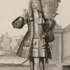
Those of you who followed my building of the Swan 42 racing yacht may experience some temporal whiplash as the Wayback Machine moves the shipyard some 300 years into the past. Even though the scale will be about the same, the materials, methods, and style will have little or nothing in common with the last project. We leave the clean lines and millimeter accuracy of a rich man's toy for the rough outlines and incomplete draughts of a pre-Colonial pirate ship.
Queen Anne's Revenge was the flagship of the notorious pirate Edward Thatch (incorrectly called Teach), known as Blackbeard. In barely more than a year and a half, from the summer of 1717 to November 22, 1818, he and two other pirate leaders put together a large fleet that took numerous merchant ships, looting them and holding any worthwhile captives for ransom while taking any willing sailors into his piratical crew. He was hardly the most notorious or bloodthirsty pirate, but he captured the popular imagination with his large fierce black beard and his habit of placing lit rope matches for his weapons into his hair during a battle.
The origins of the ship herself are not definitively known. It is thought that she was built in about 1710 as a small frigate of about 300 tons known as La Concorde, with her first cruise as a French privateer during Queen Anne's War in 1711. When the war ended in 1713 with the Treaty of Utrecht her owners sent her into the slave trade. She made two profitable cruises between 1713 and 1717, taking slaves from West Africa to the French colonies in the Carribean and capturing prizes on the return leg back to France. On November 28, 1717, during her third slaving cruise, she fell afoul of Blackbeard with two armed sloops. Her crew was sick and many of the cannon had been removed to make more room for slaves so she was captured easily. Below is a drawing of a similar light frigate from the early 1700s.
After renaming her Queen Anne's Revenge and adding significantly more cannon, she became Blackbeard's flagship and was used to capture numerous ships and even to blockade the port of Charleston for a week. Turning north from there in company with several smaller pirate ships on June 10, 1718 they tried to enter a shallow anchorage known as Topsail Inlet (or Old Topsail Inlet), now called Beaufort Inlet in North Carolina. Although several other ships entered safely, the larger Queen Anne's Revenge grounded on the sand bar at the entrance, as did another ship that came to her aid. After removing the valuables she was abandoned and left to the cruel mercies of the sea. Blackbeard himself lasted barely another six months until his death in November of 1718 during a battle with the Royal Navy.
The ship was rediscovered in 1996 and is now being excavated underwater in project managed by the North Carolina Department of Cultural Affairs and the North Carolina Maritime Museum, part of East Carolina University. Numerous artifacts, including several cannon, coins, navigational equipment, and hundreds of everyday items have been recovered and are being conserved. You can see photographs of the artifacts, view interactive maps of the ship's history and the wreck site, and read the archaeologists' and researchers' detailed reports if you go to the Queen Anne's Revenge website at http://www.qaronline.org/Home.aspx It is a little gem of a site and well worth looking into.
I have been asked to build two display models of the QAR for the Maritime Museum. They will be at the large scale of 1:36, yielding a model of some 48" LOA from the tip of the jib boom to the ensign staff at the stern. It will rise some 44" from the keel to the main truck with a main yard of some 22" with stunsail booms rigged but not extended. The hull is to be solid below the gun deck but open and fully detailed above. She is to have a full suit of sails with all sail handling lines, although several will be furled so the deck can be more easily viewed.
There are no plans or illustrations of the ship, so her apearance is a bit conjectural. As a basis for the model I have been given two sets of plans. The first is a simple, one-page rendering of the lines and profile of a similar small French frigate which was captured by HMS Advice and which is known therefore as Advice Prize.
I am also working from a set of drawings done by Jean Budriot of yet another light French frigate of the period known as Le Mercure. He has written a monograph that is illustrated with numerous detailed drawings of all of the bits and pieces of the ship including several profiles, cross-sections and longitudinal sections, and sail and rigging plans. However, as is his custom, there is no station lines plan from which to derive the hull shape.
These two sets of plans have to be reconciled, not only with each other, but with the known historic facts. For example, it was reported in contemporary accounts and court-martial testimony that the Queen Anne's Revenge had 20 large cannon on board when she went down. Le Mercure is pierced for 10 guns on each side, but the Advice Prize has only 9. The Mercure drawings have the channels for the fore and main shrouds set below the gunports, while the Advice Prize has them above. Le Mercure is shown with a square, open beakhead bulkhead, while the plans for the Advice Prize shows a closed in forecastle. At the stern Le Mercure has a large quarter gallery, rather than the small quarter badge of the Advice Prize. But that quarter badge is set very high, with an indication that the Advice Prize had a poop deck above the quarterdeck. These and many other details, large and small, will have to be reconciled as construction continues.
To begin with, a tenth gunport was added to the Advice Prize and their spacing was adjusted accordingly. The quarter badge was lowered and it is this resulting profile that will be used to build the models.
On this plan you can see a horizontal red line. This is my line of demarcation between the solid hull below and the open gundeck above. It is set at the level of the gundeck for the forward four ports. A tapered piece will be added at the rear half of the ship to account for the sheer rise of the gundeck towards the stern. But this line is also used as my registration plane for setting up the templates for the hull shape at the various stations shown on the plans.
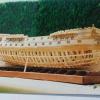
As I was working out the hull construction the first of what will surely be many problems arose. In the scale that is required, the maximum breadth of the model works out to just over 9 inches and the station lines work out to, mostly, 3 inches separation. To work from the centerline I would need wood of at least 4.5 inches wide and 3 inches thick. However, wood of that size is not easily or inexpensively acquired. Instead, I found basswood planks 4 inches wide and up to 2 inches thick. I decided therefore to piece together the hull.
As you can see in the wood blocking plan below, I started with a vertical central piece 3/8" thick to match the width of the keel. This was sandwiched on each side by a vertical lift 1/2 inch thick, then by the side pieces whch would be cut to the profiles of the appropriate station lines from the plans.
As usual with vertical station line lifts, they were cut to the profile of the appropriate station line. For each three inch station segment a two inch lift and a one inch lift were used. I also decided that the hull should be partially hollow, not only to reduce weight, but to give the stresses somewhere to go other than outward when the wood swelled with changing humidity. My solution was to take each lift and cut out the center, leaving a crescent of wood about 1 inch thick. Construction began with the gunport deck piece cut to shape and the three vertical central pieces glued to it using carpenters' squares for alignment. Then the station line lift crescents were glued in place and secured with dowels. Here you can see the first three segments glued and pinned, with the fourth made ready for installation.
This was continued from the center out to the bow and stern, with the final lifts left solid and clamped to the growing hull block. The completed hull block was left to dry for a week before the bamboo dowels were trimmed off.
Now the carving and shaping had to begin to reduce the stepped shape of the lifts. The model is so large that the usual woodworking tools were inadequate in any reasonable time frame. I therefore purchased an angle grinder and set it up with coarse 50 grit sanding discs. This was followed by a random orbit sander, also with coarse grit paper.
As you can imagine, this makes a hellish racket and leaves a hellish mess, Eye, ear and respiration protection are a must, and if you are not going to do all of it outside, you need three other things - an empty room in the basement; a big shop vacuum; and most importantly, an understanding wife. I am glad to say that I have the first two and am blessed with the third.
In this photo you can see how far the shaping has progressed. From here there still has to be a lot of hand work that is checked and rechecked as usual with station line templates. The next segment will take us through that process.
Be well
Dan
-
shipmodel got a reaction from CiscoH in Queen Anne's Revenge 1710 by shipmodel - FINISHED - 1/36 scale
Hi Michael -
Yes, another good idea. I will play with them all the next time around.
Moving ahead, I have been thinking about the methods and materials that I will have to use when it comes time to mount and rig the cannon. Once the bulwarks are in place on the hull the tumblehome is going to make rigging the cannon difficult. Then there are the deck and hull plank details that have to be worked out. . . . etc. . . etc. I decided that making a mock-up of a gun station would help me work out some of the kinks.
The first issue was how to cut the gunports through the bulwarks and create the rebate for the lid. I wanted them all to be the same size and square. The method that worked for me was to create a square tube of 1/32” wood glued at the corners. Here you can see it slid through a hole cut in the bulwark. With a small piece of bulwark like this, I could cut it on the band saw before attaching it to the base plate. On the model I will have to pierce each gunport and use a coping saw to cut the square hole.
Here it is from the side. You can see that it runs parallel to the deck, so the lintel and sill will be level. With it in this position I marked out the line where the box and the outer bulwark face met. The box was removed and cut along the line.
The cut face was sanded, and the box reinstalled in the hole, but slid in just short of the outer face of the hole.
In the closeup you can see the even and smooth rebate formed this way. The back side was marked, the box removed and cut down, then reinstalled and glued.
When the glue was dry the back side was sanded smooth with the inside of the bulwark. The rough edges and gaps will be covered by the bulwark planking. All the gunports should be identical if I slice similar sections from the same tube.
Construction went very quickly. Too quickly. I forgot to stop and take photos. Here is the completed gun station. It represents one of the midships cannon in the waist with the high bulwark and the gangway overhanging the gun.
If you look at the bulwark, you will see that it has been raised about 1/8" from the first few photos. It reminds me not to take measurements from the plans without checking them against the rest of the details that have to fit. This would have been a disaster if it happened on the actual bulwark piece.
The deck layout is taken from the plans, with the raised binding strake used by the French set just outside of the grating. While doing this I discovered that the gratings that I made earlier will have to be modified. The French did not use the high coamings which the English did, and which I built. The QAR would have had gratings set into the deck, but crowned even more than the deck camber/round up. I took an extra piece of grating and sanded it down at the sides and across the back until it fit the curved profile.
The deck is laid in holly, with birch bung covers. I know that there are good arguments to be made for making them pronounced, and just as many for making them invisible. I chose to take a middle course and try to make them visible, but not distracting.
Here is the cannon rigged with its breeching rope turned into rings in the bulwark. The rope was laid up from DMC cotton line to a diameter of 0.6” (scale 6 inch rope). It was stained and sealed with Minwax. There is still some fuzz, but I am working on a few solutions.
The gun tackle are hooked to eyebolts. The blocks are 4mm singles from Warner Woods West (6” in scale). The hooks are tied into their strops and the block closest to the bulwark has the running line tied into its becket. The line is J.B. Coates “Dual Duty Plus” that measures out to 0.015” This is a little thin, but I prefer the look to that of a thicker line.
I could not find acceptable photoetched hooks on the market, so I made them from 0.020” iron wire. The sequence below shows how I use my orthodontic pliers to bend the wire around to meet itself, then the eye that was formed is bent back to center on the shaft. To make an eyebolt it is clipped off at this stage. To make a hook I continue the bend to stage 3. Moving the pliers out just a bit the wire is bent back toward the eye, then clipped off, opening the hook.
The smallest hook I can make this way is just under 5 mm (7” in scale). This is a bit large, but acceptably small, and the 50 that I needed were done pretty quickly.
The outer bulwark planking was cut from birch veneer with the edges colored with indelible marker. I experimented with contact cement as the adhesive. I painted a thinned layer on the bulwark substrate and let it dry. The planks were painted but installed when the glue was still a bit tacky. This gave me quick adhesion but just a little ‘wiggle room’ before it set. The bad news was that the contact cement dissolved the indelible ink and threatened to spread it to the surface of the planking. I will change to a water based marker in the future.
Treenails were drilled and installed, then the planking was stained. I used Golden Oak, but did not thin it enough and I think the color is too dark. Neither the treenails nor the moldings show up to good effect.
The gunport lid was made up as usual from several layers of wood glued with crossed grain. The hinges are blackened brass strip pegged with iron wire. The strips were left long beyond the back edge of the lid and were ground down to square cross section. These pins were inserted and glued into holes drilled into the plank just above the lintel of the gunport. Hinge barrels were made from short sections of blackened brass rod.
Small eyebolts were made and fitted to the outer corners and a bridled lifting rope tied. The lead is through a hole in the bulwark above the gunport and belays to a cleat above the gun.
Of course, Pirate Pete had to show up to inspect the work. He seems to fit well into the scene.
He even looks the right size for the gangway, although he can use a rope railing on the caprail.
Overall, I would say that the two days spent on the gun station were well worth it for the time that will be saved over the long run, and the problems that will be avoided.
Be well
Dan
-

 shipmodel got a reaction from popash42 in Queen Anne's Revenge 1710 by shipmodel - FINISHED - 1/36 scale
Hi Michael -
Yes, another good idea. I will play with them all the next time around.
Moving ahead, I have been thinking about the methods and materials that I will have to use when it comes time to mount and rig the cannon. Once the bulwarks are in place on the hull the tumblehome is going to make rigging the cannon difficult. Then there are the deck and hull plank details that have to be worked out. . . . etc. . . etc. I decided that making a mock-up of a gun station would help me work out some of the kinks.
The first issue was how to cut the gunports through the bulwarks and create the rebate for the lid. I wanted them all to be the same size and square. The method that worked for me was to create a square tube of 1/32” wood glued at the corners. Here you can see it slid through a hole cut in the bulwark. With a small piece of bulwark like this, I could cut it on the band saw before attaching it to the base plate. On the model I will have to pierce each gunport and use a coping saw to cut the square hole.
Here it is from the side. You can see that it runs parallel to the deck, so the lintel and sill will be level. With it in this position I marked out the line where the box and the outer bulwark face met. The box was removed and cut along the line.
The cut face was sanded, and the box reinstalled in the hole, but slid in just short of the outer face of the hole.
In the closeup you can see the even and smooth rebate formed this way. The back side was marked, the box removed and cut down, then reinstalled and glued.
When the glue was dry the back side was sanded smooth with the inside of the bulwark. The rough edges and gaps will be covered by the bulwark planking. All the gunports should be identical if I slice similar sections from the same tube.
Construction went very quickly. Too quickly. I forgot to stop and take photos. Here is the completed gun station. It represents one of the midships cannon in the waist with the high bulwark and the gangway overhanging the gun.
If you look at the bulwark, you will see that it has been raised about 1/8" from the first few photos. It reminds me not to take measurements from the plans without checking them against the rest of the details that have to fit. This would have been a disaster if it happened on the actual bulwark piece.
The deck layout is taken from the plans, with the raised binding strake used by the French set just outside of the grating. While doing this I discovered that the gratings that I made earlier will have to be modified. The French did not use the high coamings which the English did, and which I built. The QAR would have had gratings set into the deck, but crowned even more than the deck camber/round up. I took an extra piece of grating and sanded it down at the sides and across the back until it fit the curved profile.
The deck is laid in holly, with birch bung covers. I know that there are good arguments to be made for making them pronounced, and just as many for making them invisible. I chose to take a middle course and try to make them visible, but not distracting.
Here is the cannon rigged with its breeching rope turned into rings in the bulwark. The rope was laid up from DMC cotton line to a diameter of 0.6” (scale 6 inch rope). It was stained and sealed with Minwax. There is still some fuzz, but I am working on a few solutions.
The gun tackle are hooked to eyebolts. The blocks are 4mm singles from Warner Woods West (6” in scale). The hooks are tied into their strops and the block closest to the bulwark has the running line tied into its becket. The line is J.B. Coates “Dual Duty Plus” that measures out to 0.015” This is a little thin, but I prefer the look to that of a thicker line.
I could not find acceptable photoetched hooks on the market, so I made them from 0.020” iron wire. The sequence below shows how I use my orthodontic pliers to bend the wire around to meet itself, then the eye that was formed is bent back to center on the shaft. To make an eyebolt it is clipped off at this stage. To make a hook I continue the bend to stage 3. Moving the pliers out just a bit the wire is bent back toward the eye, then clipped off, opening the hook.
The smallest hook I can make this way is just under 5 mm (7” in scale). This is a bit large, but acceptably small, and the 50 that I needed were done pretty quickly.
The outer bulwark planking was cut from birch veneer with the edges colored with indelible marker. I experimented with contact cement as the adhesive. I painted a thinned layer on the bulwark substrate and let it dry. The planks were painted but installed when the glue was still a bit tacky. This gave me quick adhesion but just a little ‘wiggle room’ before it set. The bad news was that the contact cement dissolved the indelible ink and threatened to spread it to the surface of the planking. I will change to a water based marker in the future.
Treenails were drilled and installed, then the planking was stained. I used Golden Oak, but did not thin it enough and I think the color is too dark. Neither the treenails nor the moldings show up to good effect.
The gunport lid was made up as usual from several layers of wood glued with crossed grain. The hinges are blackened brass strip pegged with iron wire. The strips were left long beyond the back edge of the lid and were ground down to square cross section. These pins were inserted and glued into holes drilled into the plank just above the lintel of the gunport. Hinge barrels were made from short sections of blackened brass rod.
Small eyebolts were made and fitted to the outer corners and a bridled lifting rope tied. The lead is through a hole in the bulwark above the gunport and belays to a cleat above the gun.
Of course, Pirate Pete had to show up to inspect the work. He seems to fit well into the scene.
He even looks the right size for the gangway, although he can use a rope railing on the caprail.
Overall, I would say that the two days spent on the gun station were well worth it for the time that will be saved over the long run, and the problems that will be avoided.
Be well
Dan
-
 shipmodel reacted to DORIS in ROYAL CAROLINE 1749 by Doris - 1:40 - CARD
Hello dear friends,
I am touched by your comments, your words and praise mean a lot for me. Thank you very much for your support and comments. That is a great honour for me and also a commitment to make things as best as possible to be worthy of your words.
On Royal Caroline I finished a small staircase and railing in front of the main cabin:
And there are also prepared all flags printed in a laser printer on the thin cloth - batiste (I have no such printer at home, but one of my friends helped me with printing).
The biggest flag is already placed on the flagpole:
-
shipmodel reacted to DORIS in ROYAL CAROLINE 1749 by Doris - 1:40 - CARD
I have also created other crew members - a midshipman and one of the officers:
-
-
shipmodel reacted to DORIS in ROYAL CAROLINE 1749 by Doris - 1:40 - CARD
On the bow there are placed knightheads - handmade of wood and clay:
-
-
 shipmodel got a reaction from mtaylor in Queen Anne's Revenge 1710 by shipmodel - FINISHED - 1/36 scale
Hi Mark -
Good point. I will add them to the model. Thanks.
Dan
-
shipmodel got a reaction from EricWilliamMarshall in Queen Anne's Revenge 1710 by shipmodel - FINISHED - 1/36 scale
Hi Michael -
Yes, another good idea. I will play with them all the next time around.
Moving ahead, I have been thinking about the methods and materials that I will have to use when it comes time to mount and rig the cannon. Once the bulwarks are in place on the hull the tumblehome is going to make rigging the cannon difficult. Then there are the deck and hull plank details that have to be worked out. . . . etc. . . etc. I decided that making a mock-up of a gun station would help me work out some of the kinks.
The first issue was how to cut the gunports through the bulwarks and create the rebate for the lid. I wanted them all to be the same size and square. The method that worked for me was to create a square tube of 1/32” wood glued at the corners. Here you can see it slid through a hole cut in the bulwark. With a small piece of bulwark like this, I could cut it on the band saw before attaching it to the base plate. On the model I will have to pierce each gunport and use a coping saw to cut the square hole.
Here it is from the side. You can see that it runs parallel to the deck, so the lintel and sill will be level. With it in this position I marked out the line where the box and the outer bulwark face met. The box was removed and cut along the line.
The cut face was sanded, and the box reinstalled in the hole, but slid in just short of the outer face of the hole.
In the closeup you can see the even and smooth rebate formed this way. The back side was marked, the box removed and cut down, then reinstalled and glued.
When the glue was dry the back side was sanded smooth with the inside of the bulwark. The rough edges and gaps will be covered by the bulwark planking. All the gunports should be identical if I slice similar sections from the same tube.
Construction went very quickly. Too quickly. I forgot to stop and take photos. Here is the completed gun station. It represents one of the midships cannon in the waist with the high bulwark and the gangway overhanging the gun.
If you look at the bulwark, you will see that it has been raised about 1/8" from the first few photos. It reminds me not to take measurements from the plans without checking them against the rest of the details that have to fit. This would have been a disaster if it happened on the actual bulwark piece.
The deck layout is taken from the plans, with the raised binding strake used by the French set just outside of the grating. While doing this I discovered that the gratings that I made earlier will have to be modified. The French did not use the high coamings which the English did, and which I built. The QAR would have had gratings set into the deck, but crowned even more than the deck camber/round up. I took an extra piece of grating and sanded it down at the sides and across the back until it fit the curved profile.
The deck is laid in holly, with birch bung covers. I know that there are good arguments to be made for making them pronounced, and just as many for making them invisible. I chose to take a middle course and try to make them visible, but not distracting.
Here is the cannon rigged with its breeching rope turned into rings in the bulwark. The rope was laid up from DMC cotton line to a diameter of 0.6” (scale 6 inch rope). It was stained and sealed with Minwax. There is still some fuzz, but I am working on a few solutions.
The gun tackle are hooked to eyebolts. The blocks are 4mm singles from Warner Woods West (6” in scale). The hooks are tied into their strops and the block closest to the bulwark has the running line tied into its becket. The line is J.B. Coates “Dual Duty Plus” that measures out to 0.015” This is a little thin, but I prefer the look to that of a thicker line.
I could not find acceptable photoetched hooks on the market, so I made them from 0.020” iron wire. The sequence below shows how I use my orthodontic pliers to bend the wire around to meet itself, then the eye that was formed is bent back to center on the shaft. To make an eyebolt it is clipped off at this stage. To make a hook I continue the bend to stage 3. Moving the pliers out just a bit the wire is bent back toward the eye, then clipped off, opening the hook.
The smallest hook I can make this way is just under 5 mm (7” in scale). This is a bit large, but acceptably small, and the 50 that I needed were done pretty quickly.
The outer bulwark planking was cut from birch veneer with the edges colored with indelible marker. I experimented with contact cement as the adhesive. I painted a thinned layer on the bulwark substrate and let it dry. The planks were painted but installed when the glue was still a bit tacky. This gave me quick adhesion but just a little ‘wiggle room’ before it set. The bad news was that the contact cement dissolved the indelible ink and threatened to spread it to the surface of the planking. I will change to a water based marker in the future.
Treenails were drilled and installed, then the planking was stained. I used Golden Oak, but did not thin it enough and I think the color is too dark. Neither the treenails nor the moldings show up to good effect.
The gunport lid was made up as usual from several layers of wood glued with crossed grain. The hinges are blackened brass strip pegged with iron wire. The strips were left long beyond the back edge of the lid and were ground down to square cross section. These pins were inserted and glued into holes drilled into the plank just above the lintel of the gunport. Hinge barrels were made from short sections of blackened brass rod.
Small eyebolts were made and fitted to the outer corners and a bridled lifting rope tied. The lead is through a hole in the bulwark above the gunport and belays to a cleat above the gun.
Of course, Pirate Pete had to show up to inspect the work. He seems to fit well into the scene.
He even looks the right size for the gangway, although he can use a rope railing on the caprail.
Overall, I would say that the two days spent on the gun station were well worth it for the time that will be saved over the long run, and the problems that will be avoided.
Be well
Dan
-
 shipmodel got a reaction from Luca in Queen Anne's Revenge 1710 by shipmodel - FINISHED - 1/36 scale
Hi Michael -
Yes, another good idea. I will play with them all the next time around.
Moving ahead, I have been thinking about the methods and materials that I will have to use when it comes time to mount and rig the cannon. Once the bulwarks are in place on the hull the tumblehome is going to make rigging the cannon difficult. Then there are the deck and hull plank details that have to be worked out. . . . etc. . . etc. I decided that making a mock-up of a gun station would help me work out some of the kinks.
The first issue was how to cut the gunports through the bulwarks and create the rebate for the lid. I wanted them all to be the same size and square. The method that worked for me was to create a square tube of 1/32” wood glued at the corners. Here you can see it slid through a hole cut in the bulwark. With a small piece of bulwark like this, I could cut it on the band saw before attaching it to the base plate. On the model I will have to pierce each gunport and use a coping saw to cut the square hole.
Here it is from the side. You can see that it runs parallel to the deck, so the lintel and sill will be level. With it in this position I marked out the line where the box and the outer bulwark face met. The box was removed and cut along the line.
The cut face was sanded, and the box reinstalled in the hole, but slid in just short of the outer face of the hole.
In the closeup you can see the even and smooth rebate formed this way. The back side was marked, the box removed and cut down, then reinstalled and glued.
When the glue was dry the back side was sanded smooth with the inside of the bulwark. The rough edges and gaps will be covered by the bulwark planking. All the gunports should be identical if I slice similar sections from the same tube.
Construction went very quickly. Too quickly. I forgot to stop and take photos. Here is the completed gun station. It represents one of the midships cannon in the waist with the high bulwark and the gangway overhanging the gun.
If you look at the bulwark, you will see that it has been raised about 1/8" from the first few photos. It reminds me not to take measurements from the plans without checking them against the rest of the details that have to fit. This would have been a disaster if it happened on the actual bulwark piece.
The deck layout is taken from the plans, with the raised binding strake used by the French set just outside of the grating. While doing this I discovered that the gratings that I made earlier will have to be modified. The French did not use the high coamings which the English did, and which I built. The QAR would have had gratings set into the deck, but crowned even more than the deck camber/round up. I took an extra piece of grating and sanded it down at the sides and across the back until it fit the curved profile.
The deck is laid in holly, with birch bung covers. I know that there are good arguments to be made for making them pronounced, and just as many for making them invisible. I chose to take a middle course and try to make them visible, but not distracting.
Here is the cannon rigged with its breeching rope turned into rings in the bulwark. The rope was laid up from DMC cotton line to a diameter of 0.6” (scale 6 inch rope). It was stained and sealed with Minwax. There is still some fuzz, but I am working on a few solutions.
The gun tackle are hooked to eyebolts. The blocks are 4mm singles from Warner Woods West (6” in scale). The hooks are tied into their strops and the block closest to the bulwark has the running line tied into its becket. The line is J.B. Coates “Dual Duty Plus” that measures out to 0.015” This is a little thin, but I prefer the look to that of a thicker line.
I could not find acceptable photoetched hooks on the market, so I made them from 0.020” iron wire. The sequence below shows how I use my orthodontic pliers to bend the wire around to meet itself, then the eye that was formed is bent back to center on the shaft. To make an eyebolt it is clipped off at this stage. To make a hook I continue the bend to stage 3. Moving the pliers out just a bit the wire is bent back toward the eye, then clipped off, opening the hook.
The smallest hook I can make this way is just under 5 mm (7” in scale). This is a bit large, but acceptably small, and the 50 that I needed were done pretty quickly.
The outer bulwark planking was cut from birch veneer with the edges colored with indelible marker. I experimented with contact cement as the adhesive. I painted a thinned layer on the bulwark substrate and let it dry. The planks were painted but installed when the glue was still a bit tacky. This gave me quick adhesion but just a little ‘wiggle room’ before it set. The bad news was that the contact cement dissolved the indelible ink and threatened to spread it to the surface of the planking. I will change to a water based marker in the future.
Treenails were drilled and installed, then the planking was stained. I used Golden Oak, but did not thin it enough and I think the color is too dark. Neither the treenails nor the moldings show up to good effect.
The gunport lid was made up as usual from several layers of wood glued with crossed grain. The hinges are blackened brass strip pegged with iron wire. The strips were left long beyond the back edge of the lid and were ground down to square cross section. These pins were inserted and glued into holes drilled into the plank just above the lintel of the gunport. Hinge barrels were made from short sections of blackened brass rod.
Small eyebolts were made and fitted to the outer corners and a bridled lifting rope tied. The lead is through a hole in the bulwark above the gunport and belays to a cleat above the gun.
Of course, Pirate Pete had to show up to inspect the work. He seems to fit well into the scene.
He even looks the right size for the gangway, although he can use a rope railing on the caprail.
Overall, I would say that the two days spent on the gun station were well worth it for the time that will be saved over the long run, and the problems that will be avoided.
Be well
Dan
-
 shipmodel got a reaction from DORIS in Queen Anne's Revenge 1710 by shipmodel - FINISHED - 1/36 scale
Hi Michael -
Yes, another good idea. I will play with them all the next time around.
Moving ahead, I have been thinking about the methods and materials that I will have to use when it comes time to mount and rig the cannon. Once the bulwarks are in place on the hull the tumblehome is going to make rigging the cannon difficult. Then there are the deck and hull plank details that have to be worked out. . . . etc. . . etc. I decided that making a mock-up of a gun station would help me work out some of the kinks.
The first issue was how to cut the gunports through the bulwarks and create the rebate for the lid. I wanted them all to be the same size and square. The method that worked for me was to create a square tube of 1/32” wood glued at the corners. Here you can see it slid through a hole cut in the bulwark. With a small piece of bulwark like this, I could cut it on the band saw before attaching it to the base plate. On the model I will have to pierce each gunport and use a coping saw to cut the square hole.
Here it is from the side. You can see that it runs parallel to the deck, so the lintel and sill will be level. With it in this position I marked out the line where the box and the outer bulwark face met. The box was removed and cut along the line.
The cut face was sanded, and the box reinstalled in the hole, but slid in just short of the outer face of the hole.
In the closeup you can see the even and smooth rebate formed this way. The back side was marked, the box removed and cut down, then reinstalled and glued.
When the glue was dry the back side was sanded smooth with the inside of the bulwark. The rough edges and gaps will be covered by the bulwark planking. All the gunports should be identical if I slice similar sections from the same tube.
Construction went very quickly. Too quickly. I forgot to stop and take photos. Here is the completed gun station. It represents one of the midships cannon in the waist with the high bulwark and the gangway overhanging the gun.
If you look at the bulwark, you will see that it has been raised about 1/8" from the first few photos. It reminds me not to take measurements from the plans without checking them against the rest of the details that have to fit. This would have been a disaster if it happened on the actual bulwark piece.
The deck layout is taken from the plans, with the raised binding strake used by the French set just outside of the grating. While doing this I discovered that the gratings that I made earlier will have to be modified. The French did not use the high coamings which the English did, and which I built. The QAR would have had gratings set into the deck, but crowned even more than the deck camber/round up. I took an extra piece of grating and sanded it down at the sides and across the back until it fit the curved profile.
The deck is laid in holly, with birch bung covers. I know that there are good arguments to be made for making them pronounced, and just as many for making them invisible. I chose to take a middle course and try to make them visible, but not distracting.
Here is the cannon rigged with its breeching rope turned into rings in the bulwark. The rope was laid up from DMC cotton line to a diameter of 0.6” (scale 6 inch rope). It was stained and sealed with Minwax. There is still some fuzz, but I am working on a few solutions.
The gun tackle are hooked to eyebolts. The blocks are 4mm singles from Warner Woods West (6” in scale). The hooks are tied into their strops and the block closest to the bulwark has the running line tied into its becket. The line is J.B. Coates “Dual Duty Plus” that measures out to 0.015” This is a little thin, but I prefer the look to that of a thicker line.
I could not find acceptable photoetched hooks on the market, so I made them from 0.020” iron wire. The sequence below shows how I use my orthodontic pliers to bend the wire around to meet itself, then the eye that was formed is bent back to center on the shaft. To make an eyebolt it is clipped off at this stage. To make a hook I continue the bend to stage 3. Moving the pliers out just a bit the wire is bent back toward the eye, then clipped off, opening the hook.
The smallest hook I can make this way is just under 5 mm (7” in scale). This is a bit large, but acceptably small, and the 50 that I needed were done pretty quickly.
The outer bulwark planking was cut from birch veneer with the edges colored with indelible marker. I experimented with contact cement as the adhesive. I painted a thinned layer on the bulwark substrate and let it dry. The planks were painted but installed when the glue was still a bit tacky. This gave me quick adhesion but just a little ‘wiggle room’ before it set. The bad news was that the contact cement dissolved the indelible ink and threatened to spread it to the surface of the planking. I will change to a water based marker in the future.
Treenails were drilled and installed, then the planking was stained. I used Golden Oak, but did not thin it enough and I think the color is too dark. Neither the treenails nor the moldings show up to good effect.
The gunport lid was made up as usual from several layers of wood glued with crossed grain. The hinges are blackened brass strip pegged with iron wire. The strips were left long beyond the back edge of the lid and were ground down to square cross section. These pins were inserted and glued into holes drilled into the plank just above the lintel of the gunport. Hinge barrels were made from short sections of blackened brass rod.
Small eyebolts were made and fitted to the outer corners and a bridled lifting rope tied. The lead is through a hole in the bulwark above the gunport and belays to a cleat above the gun.
Of course, Pirate Pete had to show up to inspect the work. He seems to fit well into the scene.
He even looks the right size for the gangway, although he can use a rope railing on the caprail.
Overall, I would say that the two days spent on the gun station were well worth it for the time that will be saved over the long run, and the problems that will be avoided.
Be well
Dan
-
shipmodel got a reaction from mtaylor in Licorne 1755 by mtaylor - 3/16" scale - French Frigate - from Hahn plans - Version 2.0 - TERMINATED
Hi Mark -
Out of the starting blocks and into the first mile of the marathon. Glad you were able to salvage as much of v.1 as you did.
Nice idea to put the batten down on your reference line.
Following with interest.
Dan
-
 shipmodel got a reaction from mij in Queen Anne's Revenge 1710 by shipmodel - FINISHED - 1/36 scale
Hi Michael -
Yes, another good idea. I will play with them all the next time around.
Moving ahead, I have been thinking about the methods and materials that I will have to use when it comes time to mount and rig the cannon. Once the bulwarks are in place on the hull the tumblehome is going to make rigging the cannon difficult. Then there are the deck and hull plank details that have to be worked out. . . . etc. . . etc. I decided that making a mock-up of a gun station would help me work out some of the kinks.
The first issue was how to cut the gunports through the bulwarks and create the rebate for the lid. I wanted them all to be the same size and square. The method that worked for me was to create a square tube of 1/32” wood glued at the corners. Here you can see it slid through a hole cut in the bulwark. With a small piece of bulwark like this, I could cut it on the band saw before attaching it to the base plate. On the model I will have to pierce each gunport and use a coping saw to cut the square hole.
Here it is from the side. You can see that it runs parallel to the deck, so the lintel and sill will be level. With it in this position I marked out the line where the box and the outer bulwark face met. The box was removed and cut along the line.
The cut face was sanded, and the box reinstalled in the hole, but slid in just short of the outer face of the hole.
In the closeup you can see the even and smooth rebate formed this way. The back side was marked, the box removed and cut down, then reinstalled and glued.
When the glue was dry the back side was sanded smooth with the inside of the bulwark. The rough edges and gaps will be covered by the bulwark planking. All the gunports should be identical if I slice similar sections from the same tube.
Construction went very quickly. Too quickly. I forgot to stop and take photos. Here is the completed gun station. It represents one of the midships cannon in the waist with the high bulwark and the gangway overhanging the gun.
If you look at the bulwark, you will see that it has been raised about 1/8" from the first few photos. It reminds me not to take measurements from the plans without checking them against the rest of the details that have to fit. This would have been a disaster if it happened on the actual bulwark piece.
The deck layout is taken from the plans, with the raised binding strake used by the French set just outside of the grating. While doing this I discovered that the gratings that I made earlier will have to be modified. The French did not use the high coamings which the English did, and which I built. The QAR would have had gratings set into the deck, but crowned even more than the deck camber/round up. I took an extra piece of grating and sanded it down at the sides and across the back until it fit the curved profile.
The deck is laid in holly, with birch bung covers. I know that there are good arguments to be made for making them pronounced, and just as many for making them invisible. I chose to take a middle course and try to make them visible, but not distracting.
Here is the cannon rigged with its breeching rope turned into rings in the bulwark. The rope was laid up from DMC cotton line to a diameter of 0.6” (scale 6 inch rope). It was stained and sealed with Minwax. There is still some fuzz, but I am working on a few solutions.
The gun tackle are hooked to eyebolts. The blocks are 4mm singles from Warner Woods West (6” in scale). The hooks are tied into their strops and the block closest to the bulwark has the running line tied into its becket. The line is J.B. Coates “Dual Duty Plus” that measures out to 0.015” This is a little thin, but I prefer the look to that of a thicker line.
I could not find acceptable photoetched hooks on the market, so I made them from 0.020” iron wire. The sequence below shows how I use my orthodontic pliers to bend the wire around to meet itself, then the eye that was formed is bent back to center on the shaft. To make an eyebolt it is clipped off at this stage. To make a hook I continue the bend to stage 3. Moving the pliers out just a bit the wire is bent back toward the eye, then clipped off, opening the hook.
The smallest hook I can make this way is just under 5 mm (7” in scale). This is a bit large, but acceptably small, and the 50 that I needed were done pretty quickly.
The outer bulwark planking was cut from birch veneer with the edges colored with indelible marker. I experimented with contact cement as the adhesive. I painted a thinned layer on the bulwark substrate and let it dry. The planks were painted but installed when the glue was still a bit tacky. This gave me quick adhesion but just a little ‘wiggle room’ before it set. The bad news was that the contact cement dissolved the indelible ink and threatened to spread it to the surface of the planking. I will change to a water based marker in the future.
Treenails were drilled and installed, then the planking was stained. I used Golden Oak, but did not thin it enough and I think the color is too dark. Neither the treenails nor the moldings show up to good effect.
The gunport lid was made up as usual from several layers of wood glued with crossed grain. The hinges are blackened brass strip pegged with iron wire. The strips were left long beyond the back edge of the lid and were ground down to square cross section. These pins were inserted and glued into holes drilled into the plank just above the lintel of the gunport. Hinge barrels were made from short sections of blackened brass rod.
Small eyebolts were made and fitted to the outer corners and a bridled lifting rope tied. The lead is through a hole in the bulwark above the gunport and belays to a cleat above the gun.
Of course, Pirate Pete had to show up to inspect the work. He seems to fit well into the scene.
He even looks the right size for the gangway, although he can use a rope railing on the caprail.
Overall, I would say that the two days spent on the gun station were well worth it for the time that will be saved over the long run, and the problems that will be avoided.
Be well
Dan
-
shipmodel got a reaction from CiscoH in Queen Anne's Revenge 1710 by shipmodel - FINISHED - 1/36 scale
Hi all -
David, thanks for the link. It was an interesting article and fills in some gaps in my knowledge of the history of the ship and Blackbeard.
Now it is time to turn to the armaments. On any pirate ship model the cannon are going to be significant points of visual interest and the QAR is no different. After Blackbeard’s capture of Le Concord, he took the armaments from his prior ship and added them to those already on his new flagship. Contemporary accounts put the number of large cannon at 20, with an unknown number of additional smaller ones. Archaeological evidence from the wreck site confirms this.
Several six-pounder long guns have been recovered and conserved, as well as a few four-pounders, a one pounder and a swivel gun. It was therefore decided to arm the QAR with 20 six-pounders on the gun deck, with four four-pounders on the quarterdeck and two one-pounders on the forecastle. Ten swivel guns will be mounted on the rails along the quarterdeck and forecastle.
The cannon that have been examined turned out to be a mix of English, Swedish, and French manufacture, which is not surprising. Blackbeard, like all pirates, would have obtained his armaments from whichever ships he had previously captured, which might themselves have had a mixture of cannon. No carriages were recovered, but the decision was made to mount them on French style carriages since she was originally a French ship and possibly retained most of her larger cannon. Here are drawings comparing the French and English styles.
As you can see, the basic differences are that 1) the French style has a solid base plate and bumper, which widens the footprint of the carriage a bit; and 2) the breaching rope runs through large holes in the cheeks rather than looping around the cascabel. The rounded curve on the bottom of the English cheeks is not unique, and I have seen carriages with them on contemporary French models.
With so many cannon to build, I looked to the aftermarket to see if anyone had barrels that would scale out to the 6 ½ to 7 ½ foot length of the six-pounders that were recovered and still be historically accurate in shape and detail. The length scaled out to between 2.16 and 2.5 inches. I found that The Lumberyard (www.dlumberyard.com) had cast Brittania barrels that were just the right size. They are listed as 32-pounders if you are working at 1:48, but the shape is correct for the smaller caliber at my larger scale.
I carefully examined enlarged photos of the barrels and was impressed with the detail and accuracy of the reinforcing bands, cascabel shape, and bore. I ordered 40 of them, as well as 12 others for the smaller cannon. They did not have acceptable barrels for the swivel guns, and I am still looking for them.
The Lumberyard also sells laser cut carriages to fit the barrels. They were made in the English style, but I thought that I would try to modify them to the French style. I knew that I could always scratch-build the carriages, but the pre-cut ones would save a lot of effort if they could be made accurate enough and of the right style. Here is how it went:
This is how the barrels and the carriages came. The carriages come four to a sheet, which worked out perfectly. The barrels and carriages for the smaller guns are identical in everything but size. A lot of thought and care went into designing the carriage pieces, including providing two different sizes of wheels/trucks. A tip of the hat to Dave Stevens.
And here are the pieces for one cannon after being separated from the laser cut sheet. They came out easily and a little help with a sharp blade was only needed once or twice for all the pieces.
The barrels are excellent castings with no flash and almost no evidence of the mold line. But whatever blackening method was used did not ‘take’ on the metal. It was uneven, crusty, and could be rubbed off with a finger. A bit of work with a dry paper towel took the blackening off down to almost bare metal.
To re-blacken them, the contract specifications call for chemical blackening of all metals rather than paint. I first tried a product called Blacken-It, which was a disaster. The metal took on a grey, chalky surface, while an unidentified tan substance precipitated out of the solution. I had much more success with Pewter Black. I experimented and found that I had to use a fairly strong solution, much stronger than the corresponding solution of Brass Black that I use for brass. The surface that was produced was more uniform, but some of the blackening could still be rubbed off if I put some effort into it. To seal it several coats of clear matte finish were sprayed on and the end results were acceptable.
Here you can see the barrel at the top as it was received. The next one down has all of the blackening removed with a powered toothbrush. Below it is the barrel after the trunnions have been cut down and reblackened. Finally, the finished barrel after clear coating. Only the vent hole has to be drilled.
The carriage conversion started with making the base plates and bumpers. The tapered base plate was cut on the table saw with the miter gauge set to 5 degrees. The bumper was cut, attached with PVA glue, then crowned using a disc sander.
The cheek pieces were sanded smooth and the burn marks from the laser were sanded off. Holes were drilled for the eyebolts and the breaching rope through the side of the cheek, and holes for the bolts holding the cheek pieces together were drilled down on two of the steps of the cheek. A simple jig was fashioned that held the base plate up so the axle notches would be clear, and located the cheeks against the bumper. The vertical cross piece at the front held everything square. A clamp made from a bent hair clip held it all together as the glue dried.
Axles and wheels were next. As they came out of the wood sheet, the axles were square. They needed to be rounded to fit the holes in the trucks. To do this I found a piece of thick walled brass tube with the correct inside diameter. Four teeth were cut and filed into one end and a sleeve was put around it as a guide and depth stop.
This was chucked into the bench top drill press and the ends of the axles were fed into it from underneath. There was surprisingly little resistance as it cut, and I was able to control the workpiece with just my hand.
It made short work of the job, and much neater than I could have done by hand.
The trucks from the laser cut sheet were modified to make them look as if they were made up of four half circles bolted together with six metal bolts. The effect is subtle, but noticeable if not done. Next to them are several of the eyebolts located in a store here in NYC. The eye is 0.095” o.d., which scales up to 3 ½”, which is quite accurate. I could have wished that the wire was a bit thicker, but the difference is hard to see. At $2 per hundred it sure beats making them all by hand.
A test cannon was done to see that everything worked, and a detailed instruction sheet was written up, then all the carriage pieces were packed up and given into the hands of JerseyCityFrankie, who agreed to assemble all the carriages. He did an excellent job, as you can see from some of his progress photos.
Frankie also shaped and installed the quoin wedges. The handles are brass belaying pins treated with Brass Brown solution. All that was left to do when I got the completed carriages back was to make and install the capsquares and their fittings.
I started with a strip of 3/32” x 1/64” brass and developed a jig to shape it. The strip is held between the guide strips and pushed up to meet the stop on the right. The die has a short piece of steel rod set into it which matches the groove cut into the base piece and is the same diameter as the trunnions.
The steel rod is placed over the groove. With a few taps of a hammer the curve is bent into the brass. The first few tries showed me that if the base piece remains flat the short end of the strip does not bend flat but springs back a bit. To correct this the end of the plate was angled and some finishing strikes with the die held at an angle took care of the problem.
Two holes for the eyebolts were pre-drilled in the capsquare while it was still on the strip, then it was parted off. You can see in the inset that the curve is not as rounded as I might have liked, but the difference is not noticeable in the finished piece.
The capsquares were chemically blackened and tack glued in position. The pre-drilled holes were extended down into the wood of the cheeks. Two U-bolts with one very short leg were bent and installed. In the inset you can see that the one toward the rear of the carriage replicates the visible portion of the eyebolt that hinges the capsquare, while the other replicates the eyebolt for the pin that holds it down.
The final detail was the pin and chain for each capsquare. Some very fine brass chain with 36 links per inch was blackened, and bits of thin wire inserted in links about half an inch apart. The wire was bent back on itself and pinched together to form a cotter-pin shape. One pin was left long and inserted into a hole just below and behind the trunnion, while the other was cut short and slipped into the eye of the forward bolt. The gun is now ready to be mounted and rigged.
And here it is with my scale figure for comparison. I think it came out quite well and will dress up the waist of the model nicely.
Actually, there were two types of carriage that were made. On the finished model only the eight guns in the waist will be visible. These are the only ones that needed to be fully detailed. However, just to be safe I detailed the four cannon that might be partially visible under the overhanging quarterdeck and forecastle. The remaining eight will only have the end of the barrel and the forward face of the carriage visible. For these no bumper was installed and the capsquares were replaced with simple U bolts. The trucks were replaced with wooden chocks that raise the cannon to the correct level and will provide enlarged glue surfaces when the cannon are installed.
So here is a complete set of all the six-pounder cannon for one of the models. The remaining small cannon will join them shortly.
This was a longer entry than usual, so feel free to ask if I have not fully explained any of the materials or methods.
Be well
Dan
-
shipmodel got a reaction from DORIS in Queen Anne's Revenge 1710 by shipmodel - FINISHED - 1/36 scale
The next deck fitting that I made was the quarterdeck companionway. On Budriot’s plans for Le Mercure it is a raised structure with hinged doors (#24) forward of the mizzen mast (#25) and aft of the watchkeeper's bench (#23). It houses the stairway that leads down to the gun deck and the captain’s cabin. As will be discussed later, I have followed the NMM plans of the Advice Prize for the overall structure rather than Le Mercure. This raises the captain’s cabin to the quarterdeck and eliminates the chicken coop (#27), the whipstaff slot (#26) and the cabinets (#28 and #29).
With the changed layout there is some question if the large companionway would still have been on deck if the captain would not be using it, or would it have been more of a simple open hatchway, perhaps with an open railing? The answer is unclear, but since there is some justification for retaining it, I am doing so.
Here are Budriot’s plans. I have followed them, except that the strap hinges on the roof have been modified a little to make them stronger.
Construction was pretty straightforward. A coaming was built with lap jointed corners in the same way that the hatch coamings were made. Three sides were fashioned with birch planks over a solid sheet to fit inside the coaming. Internal corners were strengthened with square stock and the external corners were dressed up with cherry veneer. A crosspiece was fitted and glued at the top edge of the structure to keep it all square. This is the stage of construction on the right.
On the left the two planked sections of the roof and the front doors have been added and the piece is complete, except for a final stain and finish. The bottom of the coaming has been left square unstill it is installed on the slanted and cambered quarterdeck.
Here is it from an oblique viewpoint so you can see all the details.
The construction techniques are fairly simple and incorporate a number that have been discussed in dealing with prior fittings and structures. The only new technique is for the hinges. I started with 1/16” brass strip (2” wide in scale) and bent one end around on itself using a needle-nosed wire bending pliers. You can get these from dental supply houses, or from your child’s orthodontist.
Once it is bent around on itself, it is tightened up as much as possible. Using this strip the smallest eye that I could form was about 0.028” i.d. I decided that this was acceptable in this scale.
The hinge strap was pre-drilled for 0.020” iron pins that will secure it to the wood. Here I have marked out the locations of the holes and the strap length for the door hinges.
After drilling, the hinge was parted off from the strip and chemically blackened. Here it is installed on the door. You can see the iron pins that go through the door and were clipped off short. The hinge sits on an “L” shaped piece of wire that goes into the doorpost.
The hinges for the roof were made in the same way, except that the straps are longer. Two matching hinges were installed facing each other and a pin was epoxied into the outer one with the inner one allowed to rotate freely.
Here is the completed companionway with Pirate Pete inspecting its quality.
And here it is with the doors ajar, ready for Pete to descend the stairs.
It was probably not necessary to make the doors operable, but it is one of those little details that keeps up my interest. I will know that it is there, even if the doors never move after it is displayed in the museum.
Be well
Dan
-
shipmodel got a reaction from DORIS in Queen Anne's Revenge 1710 by shipmodel - FINISHED - 1/36 scale
Thanks, Vic. Nicely stated, not understated at all. Thanks too for the likes.
This week I got some work done on the hull despite the snow.
The wooden plates of the upper hull have been cut and bent to the required shapes. The portion from the stern to the end of the waist is fairly flat, with a consistent 13 degree tumblehome. It was cut, fitted to the rabbet cut into the solid lower hull, and screwed in place. Temporary support blocks were fitted to the inside face which also support the dummy quarterdeck that you can see in the photos. The transom piece has been cut and temporarily fitted in place as well.
The bow section is much more complex. In place of the open bow deck with a flat beakhead bulkhead, the ship had a closed bow. At the waist it has the 13 degree tumblehome, but at the cathead it actually has an outward flare as if it were still open. Then when it comes around to the stem it is vertical. To accommodate these requirements, the foredeck corners are bumped out, making it less rounded and the deck overhangs the lower hull.
I derived the shape of the quarterdeck from the plans and cut a dummy deck. This was mounted at the correct height on a sturdy block and screwed into the solid lower hull on the centerline. Rough patterns were cut from cardstock and transferred to ¼” basswood, which was cut oversize at the top. Multiple dados 3/16” deep were cut across the pieces, closer together at the tight bend at the corner. The pieces were wet for an hour in a bucket of water, then forced into shape in the hull rabbet and against the dummy foredeck. They were screwed in place and the top line marked out above the foredeck. The pieces were removed and trimmed, then reinstalled and left to dry.
This is where you see it in the photos, with a dummy stem piece in place. Although I have never used this method of both kerf and wet bending together in a model hull, it seems to be working out pretty well.
Meanwhile, I continued with some of the deck pieces that will be needed. Here is the bench that sits on the quarterdeck for the captain’s convenience. I’ve never seen this before, but Budriot has it on the plans. If anyone has seen such a fitting, I would be very interested.
Here are his drawings.
And here is how the completed bench looks, with some of the components. The primary wood is birch, with cherry veneer for the accent work and arms.
The arms were built up of four layers of veneer stacked vertically. The outer layers of the horizontal pieces for the arm are sandwiched around two vertical pieces for the post. On the right is the arm piece shaped oversize to the desired curve. On the left it has been trimmed to shape.
Here is the first one completed from another angle.
And here are the finished pair with my scale figures for comparison.
I also set up for the four ladders which will connect the gun deck at the waist with the gangways between the quarterdeck and foredeck. They have only four treads but are wider at the base than at the top.
As you can see in the photo, my ladder technique is to make a long box from which separate ladders can be parted off individually. Two matching rectangular pieces for the stringers have dados cut across the grain. A web of veneer sheet woods are fit into these slots for the treads. The grain runs across from stringer to stringer.
Sorry, this enlargement did not come out too well, but you can see how the dados are cut halfway through the stringer material.
The ladder block was set up so everything was square or, rather, symmetrical until the glue hardened. A ladder was parted off on the band saw at the calculated angle, cleaned up, and finished. This angle might not be right, so I only made one to test. Whatever the ultimate angle, the rest of the block should be enough for at least the four needed for the first model.
I will need a pair of longer ladders from the quarterdeck up to the poop deck on top of the captain’s cabin, and a wider one from the quarterdeck companionway down to the gun deck. They will be made in much the same way.
The companionway itself will be next.
Be well
Dan
-
shipmodel got a reaction from popash42 in Queen Anne's Revenge 1710 by shipmodel - FINISHED - 1/36 scale
Hi all, and thanks for the comments and likes.
The next set of independent pieces to be made were the three hatches with gratings. One two-part one goes on the quarterdeck, while the other two go on the gun deck under the boat in the waist. My method for making gratings is a bit unusual in that it there is little or no measuring done with a ruler or calipers. Everything is done relative to the thickness of the saw blade that is used. I developed this method because I only have a Preac saw. A milling machine might make the whole process easier, but I work with what I have.
The first thing is to set up the saw to make square section sticks of wood whose dimension will be about 2 inches in the scale being used. This then has to match the thickness of a saw blade that you have. For the small grating I used a slitting saw blade that was 0.032” thick.
To set the saw I sandwiched that blade between a second blade and the rip fence. The fence is snugged up and locked down. The cutting blade does not have to be the same thickness, although in this case it was since I have two blades of that same thickness.
[These first nine photos are in black and white because they are taken from another presentation on making much smaller gratings].
Several sticks 0.032” square were cut from a sheet of hardwood. Only a few are needed. Then the blade that matches the sticks is mounted in the saw, if it is not already there. Two of the sticks are sandwiched between the blade and the fence which is snugged tight and locked down.
One stick is removed and a short section of the other is held firmly against the fence and tacked in place with extra thin cyano. Care is taken to see that the fence is not glued to the table.
The fence is removed, leaving a guide strip parallel to the blade and one blade thickness to the right.
A rectangular piece of hardwood sheet is selected and held against the guide strip and the miter guage. The blade height is set up to cut just a tiny bit deeper than halfway through the sheet.
The wood is run over the blade, cutting a channel one blade thickness from the end.
The wood is flipped over and the slot that was just cut is placed on top of the guide strip.
The wood is run through again, cutting a second channel two thicknesses to the left of the first channel.
The balance of the sheet is cut in the same way, making a series of channels parallel to each other and spaced two blade widths apart.
Here is the grating sheet for the QAR. At my scale I needed sticks and channels that were about 0.055”. I took one of the 0.032” blades and stacked it together with a 0.023” blade, making a 0.055” dado blade.
Actually, for the small grating I used Portia Takakjian’s technique. This involves cutting lots of square sticks as well as cutting cross channels across the first ones. The cross channels are filled with the sticks and everything is glued together. When dry the solid back of the sheet is ground off with a sanding drum. This works well for a small grating, but the wider blade did not cut as cleanly so I kept getting tearout. Also, I needed more than 25 square inches of grating and did not look forward to grinding off so much wood.
Instead, I removed the guide strip and set the saw to cut 0.55” using the blades as spacers again. Strips were parted off the sheet until the material was used up. I call them toothed strips for obvious reasons.
Three quarters of the toothed strips were cut into thirds and interlocked with the remaining long strips.
This created a grating sheet about 2 ½ by 7 ½ inches. This was only enough to make the gratings for one of the models, so a second grating sheet was made in the same way.
From the sheets I cut out sections for the grating sizes that I needed, sanded the edges flush and gave them a coat of slightly darkened matte finish to protect them from glue stains when the coamings get built around them.
Overall, this method worked well for me, and I will try it in smaller scales in the future. A tip of the hat to Charlie Files, inventor of the Preac, wherever you are.
I will have the log of making the coamings in a few days. Until then, be well.
Dan
-
shipmodel got a reaction from popash42 in Queen Anne's Revenge 1710 by shipmodel - FINISHED - 1/36 scale
Hello again.
I trust that everyone has recovered from Thanksgiving, Hanukkah, and all that tryptophan in the turkey. Not to mention all the family that may have descended on you as they did to us. I have a greater appreciation than ever for the wit and wisdom of Winston Churchill. . .
I did manage to get in some work on the hull. The lower portion of the first hull was fully shaped using templates as usual. The aft portion of the gun deck was built up with tapered stacks of basswood to match the rise of the sheer line, then sanded down to make a smooth curved surface at the centerline. A camber (round-up) of the deck of 1/8" from the centerline to the bulwark edge was plotted from the plans. I marked and sanded this into the gun deck surface. When I was happy with the underwater shape and the deck curves, the hull was given its first coat of sandable primer. Rough areas, uneven curves, and other problem spots were dealt with and re-primed.
Although the hull will probably be tweaked some more, I started working out the bulwarks and hull sides above the gun deck. Here you can see that the main bulwarks have been cut from 1/4" basswood to the shape taken from the NMM draught. From the transom and taffrail to a point just aft of the forecastle the ship's sides were a consistently flat shape. There will be some curves sanded into them later, and they will be bent to match the perimeter of the deck, but for the internal support, the basswood pieces are more than adequate.
At this point they are still flat and straight. They sit with a tumblehome of 13 degrees using the blocks and clamps to get and idea of what they will look like and how they will fit.
Here I am cutting the rabbet that the bulwarks will sit in. Since I do not have a router, I cut the horizontal channel using the Dremel grinding disc. I have the large circular saw blade, but the thought of freehanding the cut with the agressive teeth was a little too scary. It took a good deal longer, but if I had slipped I figured that all I would get would be a sanding injury, not an opened vein.
Once the horizontal channel was ground, I used a wood chisel to make the vertical cuts that removed wood and established the rabbet. It was cleaned up with sanding blocks, then the inside face was angled to match the tumblehome.
Back in Brooklyn I returned to the masts. Here are the two topmast blanks. As shown on the plans, the mast shaft is offset towards the aft edge of the square heel. In the photo you can see that I used the Preac to cut down the forward face of the square blank.
At the heel you can see it more clearly.
The port and starboard faces of the stick were cut down half the amount that the forward face was, which squared up the stick again. Now I could mark it out, cut the tenon with the table saw, then plane it octagonal as was done with the lower mast.
The square stick was shaped to a cylinder. Then the upper and lower edges of the wider section that holds up the trestletrees was cut on the table saw. I whittled the wood down till it matched the cut channels. Then the balance of the wood was removed with sanding drums, sanding sticks and sandpaper.
At the heel you can see the construction sequence clearly. The three sides are reduced with the table saw, then shaped with the sanding drum to fair the offset round shaft to the square heel.
Once the heel is shaped, a fid hole is drilled through and squared up with a needle file. Two mock sheaves are drilled and shaped on an angle that ultimately lines up with eyebolts on the cap. These are for the leads of the lifting ropes. The completely shaped topmasts were give a coat of finish and set aside.
The mast caps were shaped from the plans from pear. They have the Continental humped form, with holes and grooves along the edges of the cap for the lifting ropes. They were made from a forward and aft piece, with a notched seam held together with iron straps. Straps also crossed the bottom, fore and aft faces of the cap. Here is the blank with the hole for the topmast drilled. The other has been shaped and the seam between the forward and aft pieces scribed as before. The piece was finished and the straps glued on.
The straps were drilled for 0.020" iron wire pins. These were inserted and cut off long before being glued. Once the glue dried they were cut almost flat, then peened smooth.
Four eyebolts were drilled and mounted on the underside of the cap through the supporting straps and the caps were complete.
The topmast trestletrees were cut and shaped to match the plans. The crosstrees were shaped from wider pieces of wood so they could splay out, then half-lapped into the trestletrees. Holes for the shroud lines were drilled before they were tapered per the plans, then finished.
The topmast cap was cut and shaped much like the lower caps, but these were one piece units with iron straps that could be opened when the topgallant mast was taken down. This is useful, because the truck at the masthead won't fit through the opening without opening the strap.
So here are all the components of both main masts. The second topmast, the upper one in the photo, had a knot in it that took up the stain badly. I will minimize it with a darker finish, but in the fullness of time it will be replaced and used as one of the spare spars that will fit along the open waist in the finished ship.
Here they are all set up. From the deck the mast reaches some 31 inches to the truck. This is going to be one mother of a fully rigged model.
There will probably be a longer break until my next post. I will be building the foremasts, which are almost identical to the main masts, so no new techniques will be used. I will be back when they are done.
Happy Holidays to all.
Dan
-
shipmodel got a reaction from CiscoH in Queen Anne's Revenge 1710 by shipmodel - FINISHED - 1/36 scale
Thanks for all the nice compliments.
Michael - I will trade some of my carving skills for your metalworking expertise. I just finished reading your log of the Bristol cutter and was blown away.
Ken - yes, the jaw is the major problem, but the width of the eye sockets also seemed too broad. Here is the face after narrowing. The lion is coming along nicely, but has a ways to go. If my artistic skills are up to it, I want to get a ferocious expression, but that may be hoping for too much.
After putting the lion to bed for a while, the next independent pieces that I turned to were the mast tops. By 1710 in France they were circular but without the earlier raised rim. They are built with the usual overlapping plank construction, a flat rim and radial cleats. Here are Budriot’s plans, which are almost identical to Lees’ and Marquhardt’s. This is the main top, but the fore is identical, other than being scaled down just a fraction. The mizzen top is smaller, but the construction method for all three is identical.
To build them, the first piece to be made was the square filler piece. It is just a piece of 1/8” thick scrap, sized to the lubber’s hole on the plans. The cryptic symbol on this one is left over from its use as a jig for a previous model. I cut this carefully on the Preac, as it will guide the rest of the construction.
The planks are 1mm thick birch, cut to width and long enough to span the diameter of the top. On the real ship they would have been cut thick then carved down to make the lap joints, leaving a raised portion in the center. Instead, I took a piece of the planking and cut sections the length of one side of the filler guide. These were then glued to the center of the planks with the edges matched up. When the glue was dry one edge was colored with a black marker. A completed one is just above the filler guide piece.
The cleats in the lower left are mass produced since the fore and main tops take 16 each and the mizzen top takes 12. I cut a rectangle of 1mm cherry sheet with the grain going in the short dimension. Then I glued another strip on top of one edge with an overhang equal to the width of the rim with the grain also running in the short direction. Now I could part off 1/16” wide cleats with a narrow blade in the table saw until I ran out of material. The cleats are left raw at this point and will be shaped and tapered later.
To start the platform construction, four of the lap planks are positioned around the filler guide. Two of them (top/bottom) have the thick section turned up and the other two (left/right) have the section facing down. They are glued at their overlaps and clamped tightly around the filler guide.
When they are solid it is easy to lay in the other down facing planks and glue them to the underneath planks and to each other. After the clamps are removed the platform was flipped over and the remaining planks were glued across the first sets of planks.
The center of the filler piece was located and the outer perimeter of the top was drawn with a compass. This was cut close on the band saw and left rough, to be taken down to the line on a disc sander after the rim is installed.
With the compass still set for the perimeter size, an arc was drawn on a rectangle of the cherry sheet, this time with the grain running the long way. The compass was closed the width of the rim and a second curve was drawn inside the first but with the same center. Three more pieces of cherry were stacked under the first and glued together at the upper corners and lower center only, not where the rim pieces will come from.
The inside curve was cut on the band saw then smoothed to the line with a sanding drum in the drill press. The outer curve was cut large, to be sanded down after installation on the platform. After completing the second cut the pieces separated automatically. The rim pieces were cut to one quarter of the circumference of the platform using the plans to make the initial cuts, the fine tuning being done during assembly.
With the platform, rims and cleats made, I assembled them with neutral pH PVA glue. Care has to be taken to see that the cleats are equally spaced and the rim pieces match up to each other, but otherwise construction is pretty straightforward.
The shafts of the cleats were made overlong so their tails extended into the lubber’s hole. These tails were clipped off and the shafts tapered from the rim to the hole with a flap-wheel sander.
All of the corners and edges were cleaned up and rounded with a sanding stick then the top was given its first coat of finish.
Here I used Floquil clear flat, but with a few drops of my stain mixture (50% Natural, 25% Cherry, 25% Early American) added. The finish enhanced the color of the cherry while the light stain brought the tone and hue of the birch into the same color family. It even slightly enhanced the grain of the birch, as if it were older wood. This is exactly the effect that I was looking for. I think that I will be using this color palette a lot as the build continues.
The trestletrees and crosstrees were cut to length from 3mm x 6mm pear. I used the Preac to cut the notches in the trestletrees to accept the crosstrees. Tapers were sanded on all eight arms as shown on the plans, then they were installed on the underside of the platforms.
Holes for the crowsfoot lines were drilled through the forward rim. I spaced them a bit closer together at the center to account for the anticipated narrowing effect as the top curves away from the euphroe. I’ll see how that works out when it is rigged.
The elongated holes for the upper deadeye strops were roughly cut by drilling two holes side by side then using the drill bit to nibble out the wood between them.
Finally, I indicated the nails that hold the two layers of planking together where they overlap. As with the boats, these were indicated by drilling shallow holes with a #80 (0.012”) drill. A wash of stain mix was flooded over the holes and immediately wiped off. It darkened the holes without changing the color of the planks. This is a technique that I will use again as well.
There will be additional holes to mount a number of blocks under the tops, but I have not studied the rigging plan enough yet to locate them. For now, here are the six tops ready for storage till needed.
I'm up in the country this weekend, so hopefully I will soon have some progress to share on the hulls.
Dan
-
 shipmodel got a reaction from CharlieZardoz in Queen Anne's Revenge 1710 by shipmodel - FINISHED - 1/36 scale
Hello again -
Just back from the doctor, who says that a 'trigger finger' problem that I am having with my right thumb is related to the repetitive nature of the carving work. He told me to lay off for a while, and gave me a cortisone shot into the base of the thumb. Ouch ! And then it didn't work! I don't have much more to do on the first figurehead, so I am going to finish it in easy stages, then work on some larger pieces before going back to the second lion.
Here is a short report on where I am now -
This next phase of the carving is mostly a process of refining the shapes that were defined last time. For this I mostly use a series of diamond abrasive burrs of various shapes. Here is the set, purchased from Micro-Mark some time ago when Chinese tool makers hadn't started taking short cuts with quality. They have held up very well for more than a decade. The long cone in the Dremel is very useful. I use the point for lining out and small details, while the larger diameter of the base of the burr smooths and shapes larger surfaces.
The carving process with these burrs is the same as for the larger bitts - I first define the edges and planes, then refine them by rounding the corners and adjusting the angles of the planes. Raised body parts like the tail and upper arm are given some dimensionality by undercutting them slightly to create a shadow line.
All of the carving is all done by eye at this stage - the Michelangelo method - I just remove whatever doesn't look like the image in my head. Here are a series of shots with the work rotating starboard to port.
The major issue right now is the shape of the head. It is still too broad. In some photos it looks more like a lizard than a lion. You can see that quite clearly in the first enlarged photo below. This was taken with the macro setting on the camera, and some of the problem is exaggerated, but you can see what I mean. In the lower photo I used Photoshop to narrow the image about 15%, and now it looks much more leonine. I will carve it down to get that general shape.
If you haven't figured it out, the teeth are created by simply drilling a series of small holes which define the negative space between the teeth. I may use a small triangular file to refine them, or just leave them as is, since they are all but invisible uness a camera is used to magnify them.
Happy Thanksgiving to all.
Dan
-
shipmodel got a reaction from CharlieZardoz in Queen Anne's Revenge 1710 by shipmodel - FINISHED - 1/36 scale
Hi all -
Two days of carving and the first figurehead is rounding into shape. Here is how I am going about it.
I do almost all of my carving with a rotary tool and a series of ever smaller burrs and bitts. Here they are for the first stage of the carving. It includes a 1/4" diameter sanding sleeve for the Dremel plus a set of Disston burrs. Over the years I have added to the set when I found other shapes that could be useful.
Here are the ones I use most often. The sanding sleeve is at the top. From left to right we have a straight bit with a rounded tip; a straight bit with a square tip; a reverse cone; and in the Dremel is a sharp cornered reverse rounded cone. This last one is very useful for 'drawing' thin lines onto the wood that serve as landmarks for deeper carving with the other bitts.
The first carving was done with the sanding sleeve to round off the square corners and planes left by the band saw, and to get the basic side to side shape.
Now the arms are defined, which will fair into the basic shape of the lower body. The mane is rounded, which will frame the shape of the face.
The tail was pencilled in on both sides and defined, which then set the depth of the lower body. The crown was detailed, which adjusts the top of the mane. The mane was given its initial texture, which then required reducing the height of the shoulder, etc. etc. This is how I carve, with each step or detail that is worked on leading to a further defining of the adjacent detail.
So here is the current look of the first figurehead. The head is still too broad, but that is OK, as it gives me the depth of material that can be carved away for the final detailing of the face.
Next time, the final detailing.
Be well
Dan