HOLIDAY DONATION DRIVE - SUPPORT MSW - DO YOUR PART TO KEEP THIS GREAT FORUM GOING! (Only 68 donations so far out of 49,000 members - Can we at least get 100? C'mon guys!)
×

LJP
-
Posts
159 -
Joined
-
Last visited
Content Type
Profiles
Forums
Gallery
Events
Everything posted by LJP
-
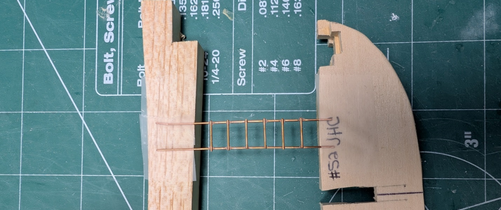
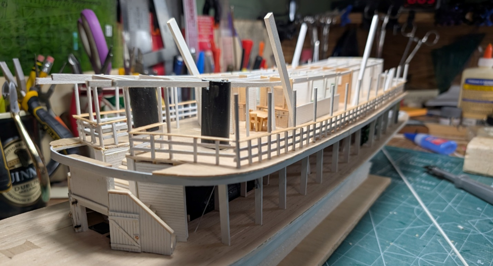
 Carlines are done. The hog chain braces are still loose and need to be cut to length. I also included a template for the pilothouse. There are a few other cutouts on the hurricane deck. One is a (? viewing?) hatch that may have been used to allow the pilot a better vision when docking. Not completely certain what this was for but several of the Ryan built boats had these. Any of your ideas would be greatly appreciated. The other is the opening for the ladder from the boiler deck to the hurricane deck. This is what the unpainted ladder looks like. I get more model time and more done during a Wisconsin winter when the weather is conducive to indoor pursuits. Now it is time to plank the hurricane deck.
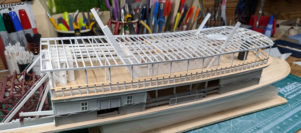
-
Keith, Thanks! Love your Billy build. Where you get these ideas and such a small scale never ceases to amaze me! John, Thanks for the kind words. Hope you are enjoying your summer down under. Cathead, Lucked out on JHC with the straight rails. I was not as lucky with Thistle, that was rounded at the bow. To all: Best of the Seasons to you and yours, and a great 2026. (I am NOT ready to acknowledge the start of a second quarter century in the 2000's. Seems like only yesterday...) LJP
-
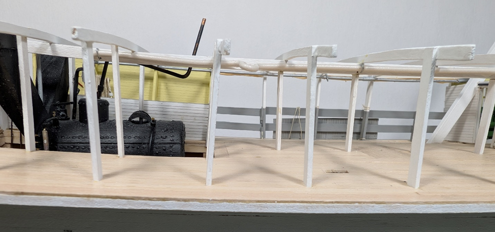
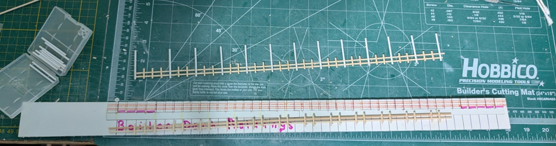
Got the railings done. This is the same template that I used to make the railings for Thistle. And the finished product on the boat. The hog chain braces will be cut to length and glued in at a later step. Now time to add the carlines, cut the beams to length and plank the hurricane deck.
-
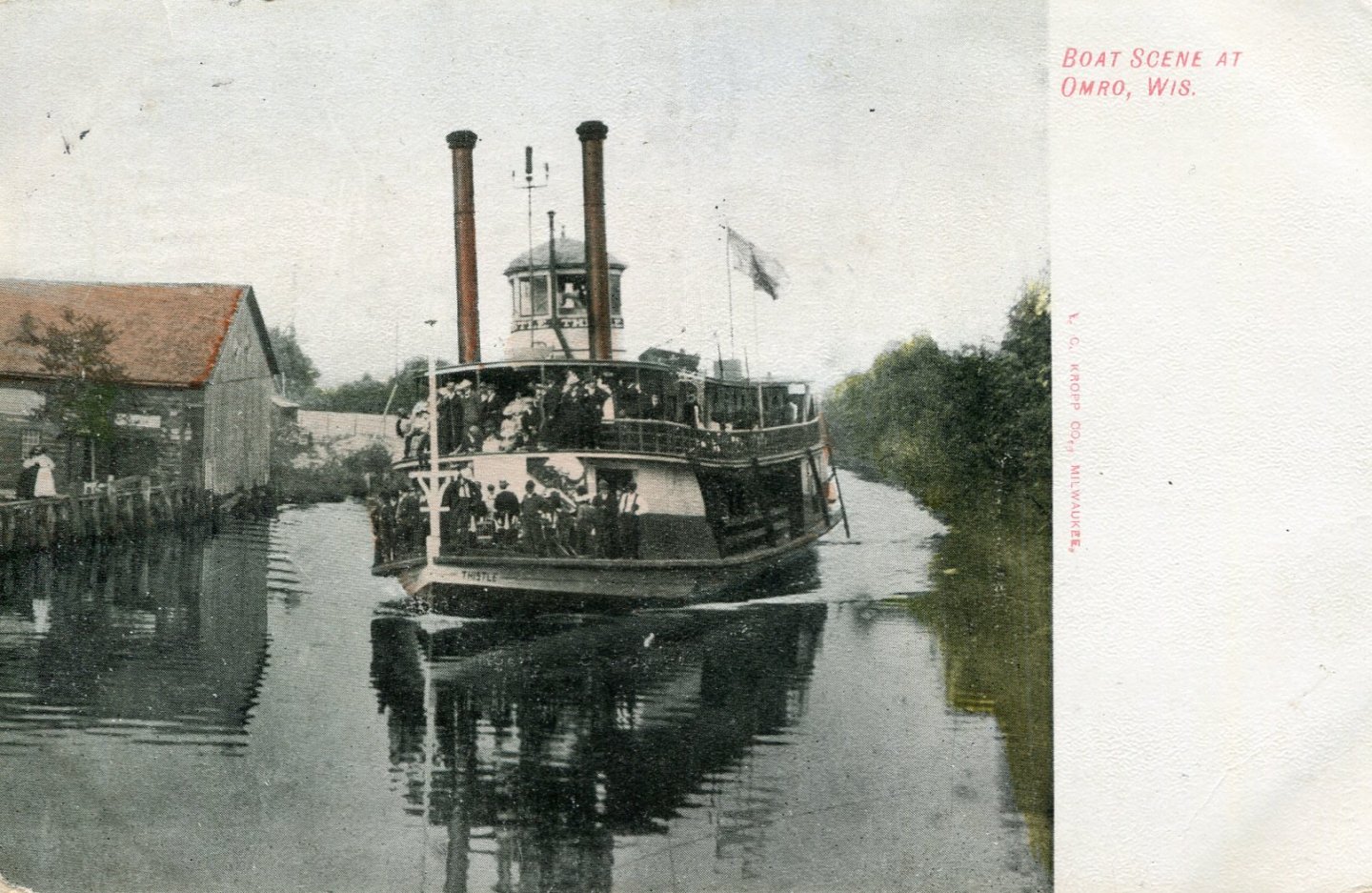
Hi John, JHC/Thistle had bow and stern sheer, probably due to travelling on the Winnebago Pool: Lakes Winnebago, Poygan, Winneconne & Butte des Morts. Sheer was normal for those boats. Those lakes could be volatile. As Thistle, there were reports of pottery crashing to the deck, furniture swept overboard, and buckets broken on the sternwheel. The Aquila had its superstructure destroyed, Cook had barges capsize and sink. The angle of my photo really accentuated the sheer; it was not that severe. One of my photo postcards shows Thistle/JHCs bow sheer: As for the hurricane deck being named as such, I have no idea. Maybe you or others can give us the history on that. LJP
-
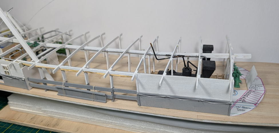
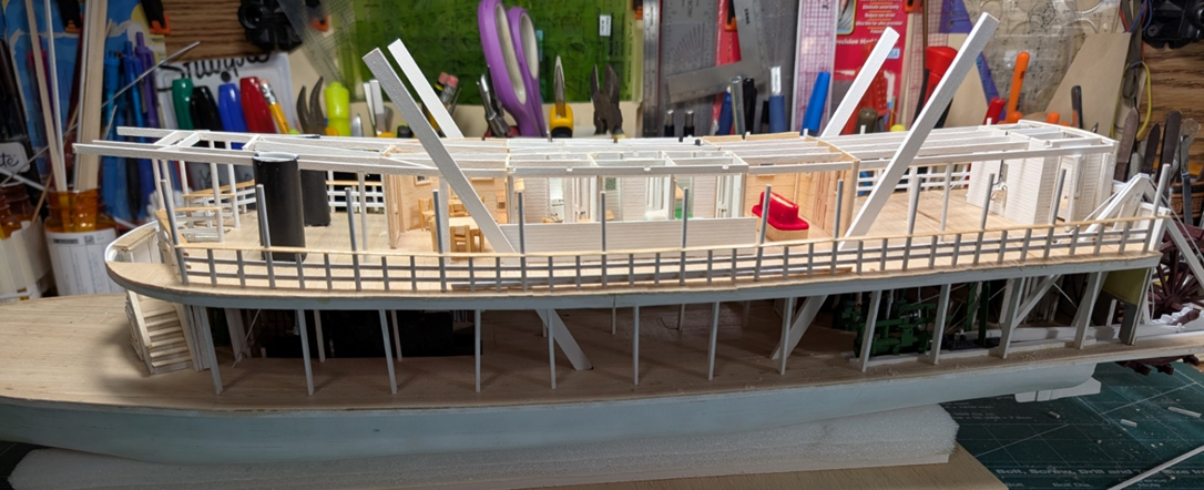
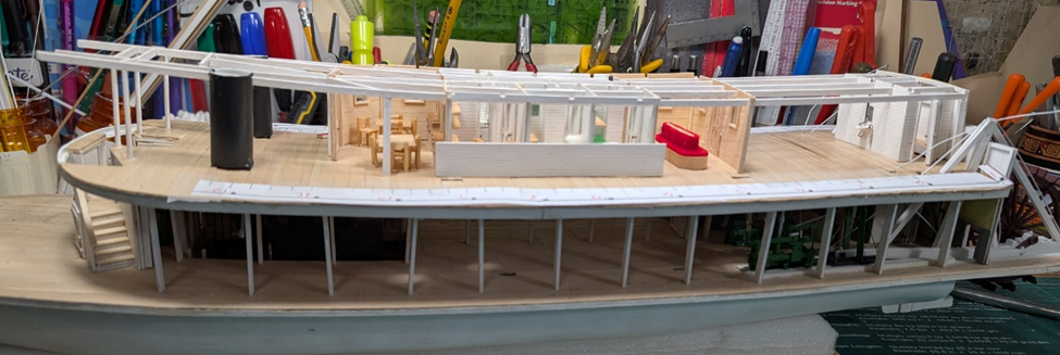
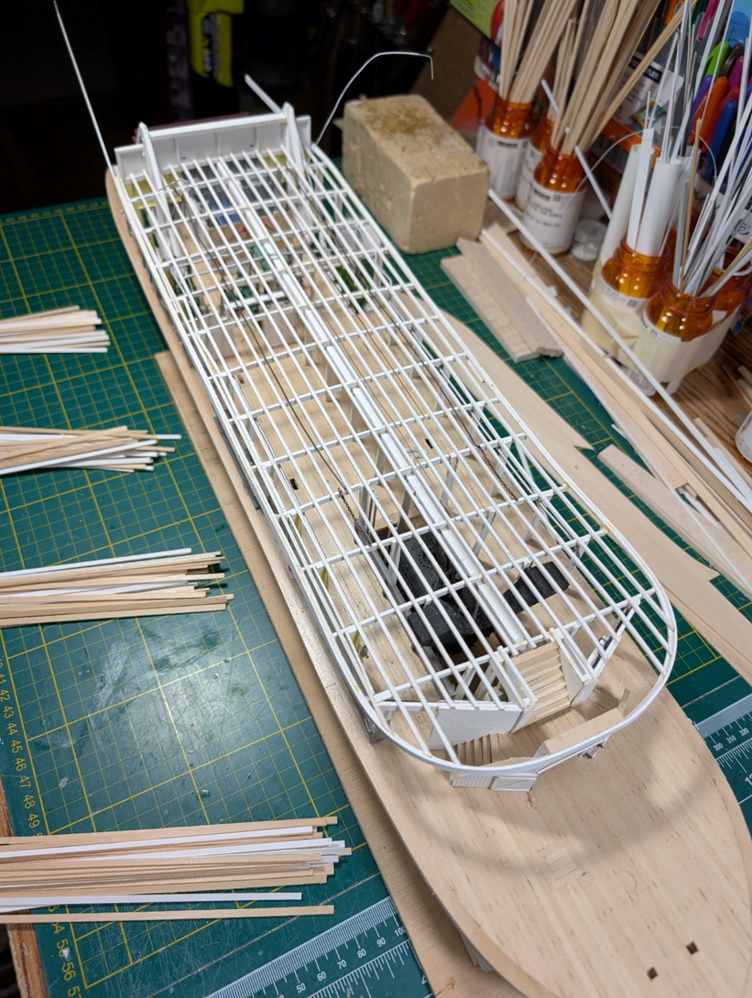
I installed the hurricane deck beams. I placed some of the stanchions and the cover for the stacks. I will still need to cut the beams to length at the bow and add more of the stanchions on the beams after the railings are set. The railings will be my next project. The paper on the boiler deck shows where the stanchions and spindles for the railing will be located. I will use a template for the railings that I used for Thistle. After that, I can add the carlines and the rest of the stanchions on the deck beams. A long way to go yet, but JHC is beginning to look like a real sternwheeler.
-
Hi John! The ladies always did have a nicer arrangement than the men, even on day boats like JHC. Usually, it was much larger than the 15 by 15 on JHC and included carpets, maybe a piano, and lots of easy chairs. And entrance into the women's salon was prohibited to the men. Cathead, I had done a more limited interior on Thistle but decided to do more since JHC will be open to view. My eyes and fingers are not what they once were, but I refuse to give up and do the best I can. I am waiting for your next build.... Take care all & best of the Holidays to you, LJP
-
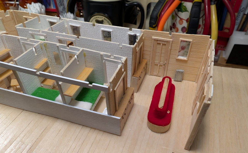
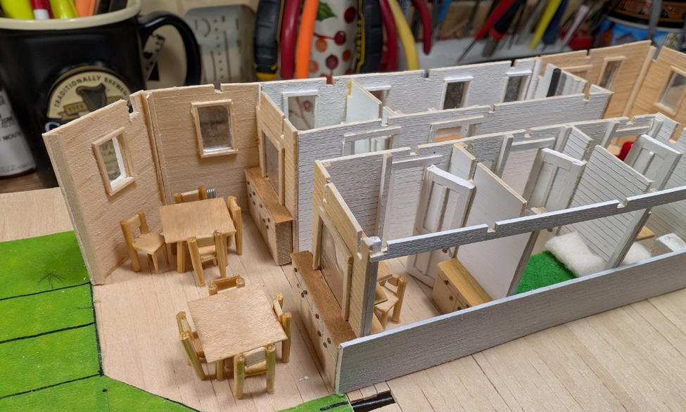
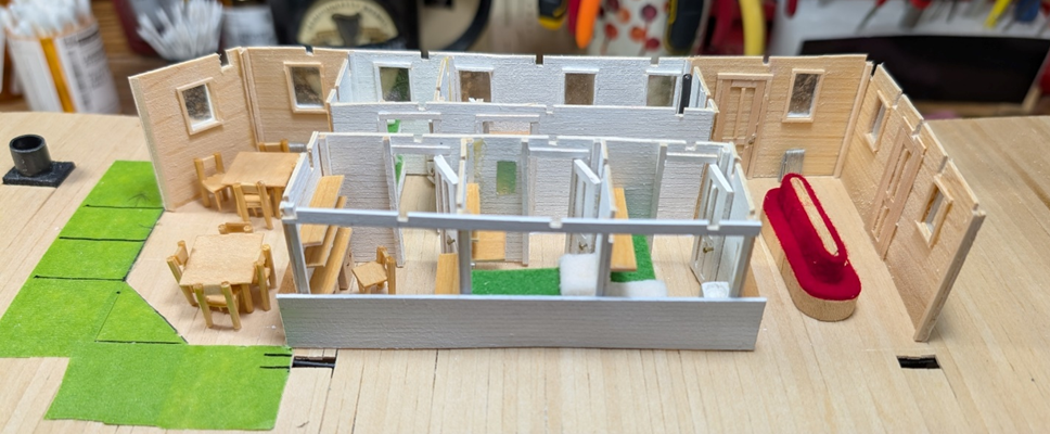
Next step is done. Port side rooms have been completed along with lots of miniature furnishings. The women’s salon included a central seating area, along with mirrored built-ins and a radiator. The first stateroom was the cook’s. It includes an Astroturf bed 🤣, shelving above it, and a sink in the corner. The next was the Captain’s stateroom. Again, a bed, but also a work area with shelves and a worktable. The Purser’s room had storage and work table area. Lastly, the men’s smoker. A couple of tables and chairs, mirrored built-ins like the ladies salon and a partially hidden radiator. No alcoholic beverages, JHC was a dry boat but you could BYO. I still need to add the front door panel. The next step is to begin putting in the beams and carlines. I will need to add some stationaires and whatever the metal protector around the stacks was called.
-
Cathead, No, JHC stayed with the Astroturf. Real grass would have required a faucet in the stateroom to water the grass, a lawnmower to cut the grass, and a horticulturist to maintain the grass. Way too expensive on a working boat. 🤣 LJP
-
Cathead, TOO FUNNY! So I suppose the blue employee bunks on the main deck are Boise State Blue Astroturf? LJP
-
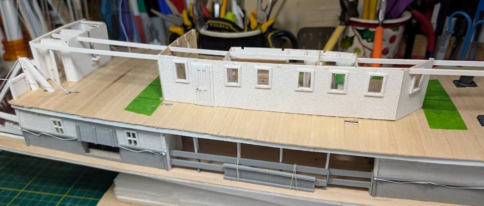
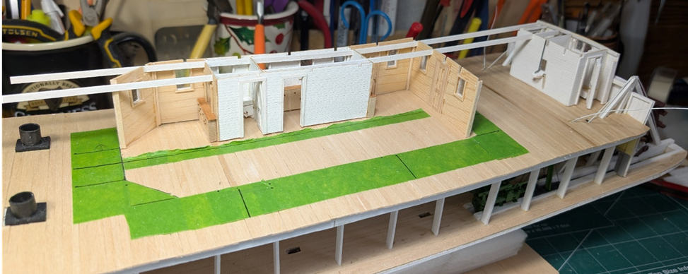
I have started assembling the boiler deck superstructure. This is the starboard side rooms. The interiors will be hidden when built - except for any window views. The windows were single pane and slid down into recessed panels. The interior view shows the men’s smoker forward and women’s salon aft. I still need to build and populate those rooms. The port side will be somewhat open to allow the room details to be viewed. JHC had a combined galley/kitchen. It was initially a working boat with passengers a secondary interest and no overnight accommodations. The dining room was either the open area between the women’s saloon and the toilets, or the main deck if available. The forward stateroom was for the engineer and fireman. I still need to build the entire port side along with all of the furnishings. After that, the railings – which I expect will take a lot of time based upon my experience with the Thistle.

-
Hi John, Thanks for your support! Hi Cathead, No clarification needed. I loved your comments on the November 8 post. I wish I could remember all of the comments and tips from everyone's builds. I would then be a much better model builder. LJP
-
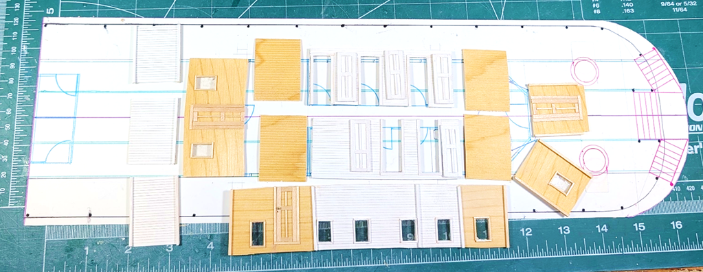
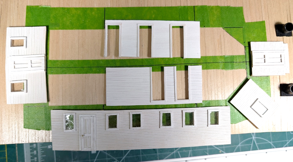
I have been working on the walls for the staterooms, saloons, &c. This is what the walls look like for the boat interior. And the reverse side for the exterior. I continue to use mica to simulate the glass in the windows. This really works well compared to the clear plastic that I used in Thistle. Again, thanks for the suggestion. I need to create the furnishings before I can assemble the superstructure. I will use a modified description of what was used on the sister boats, Leander Choate (II) and Paul L. This means a women’s saloon, a men’s smoker (these were both 15 by 15 feet), a galley/kitchen, three staterooms for the Captain, Cook and Engineer, and lastly a multipurpose office used by the purser, captain and small mail and package storage.
-
Hi Cathead, Loved your Bertrand and stole some of your modeling ideas. Arabia too. LJP
-
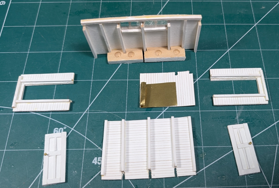
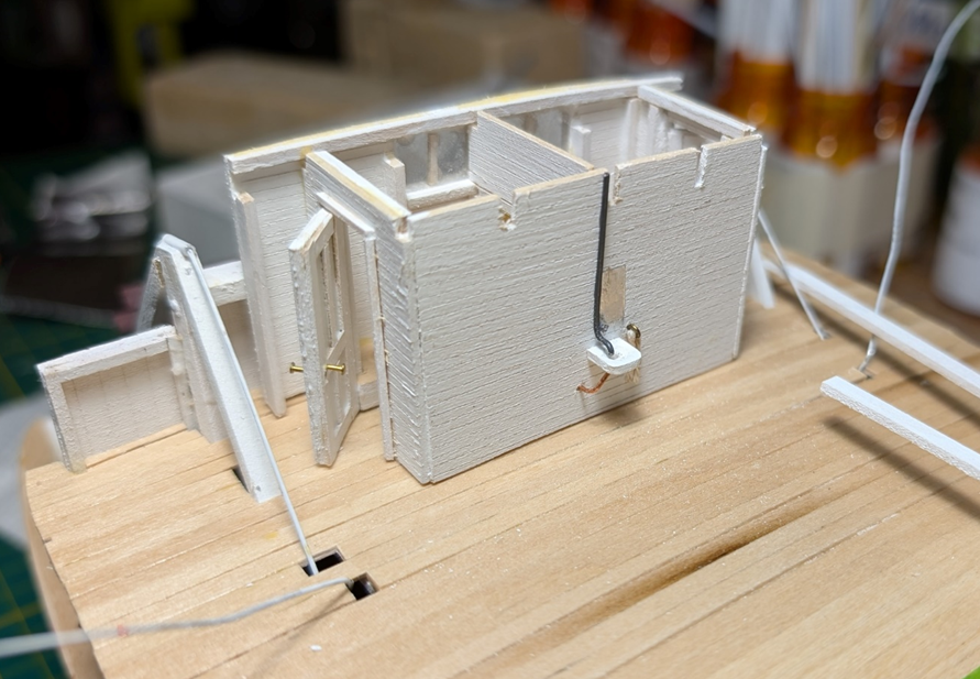
I am probably obsessive compulsive to do this, but I “Outfitted” the men’s and women’s toilets. This really took a long time to complete (but I was also away for several weeks) and hopefully the rest of the cabins and furnishings will go faster. Please note this is build number two (Pun intended) as the first attempt was not good. Amazingly, the later Ryan boat the Leander Choate (II) 1908 actually listed the dimensions of the toilets: 6 by 6. The dimensions of virtually nothing else was ever listed, but for some odd reason, this was. Since both JHC and Choate had the same width (and eventually the same length), I used these dimensions. The first photos are the interior look that will be partially hidden once assembled. I have no idea if this was a “two holer” with a urinal trough in the men’s side. As one who used this type outhouse in northern Wisconsin camps, privacy, and the sensation of smell leave much to be desired. The false transom has drain holes that actually showed up on some photos. Again, this is gross but effective as the spray from the paddlewheels would help clean this. And the completed model. This is self-standing and will be affixed later. I would suspect there was a hand wash sink and mirror (and dirty towel to go with it) so I added this beneath the water tank which was located on the hurricane deck. Now off to building the staterooms &c.
-
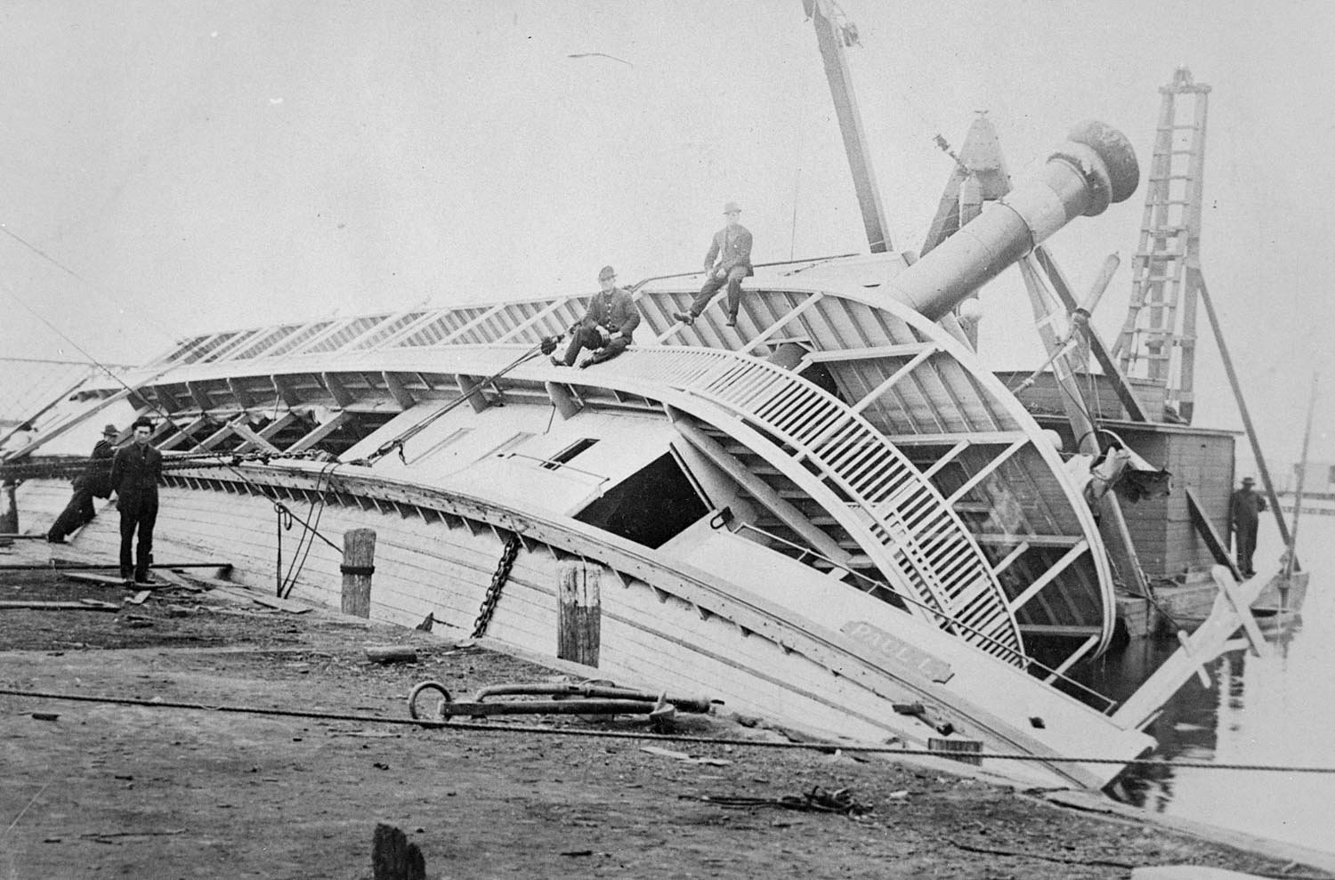
Hi Keith and John, Sorry for the real late response but I have been away. I have a photo of the capsized sister ship, the Paul L. It is difficult to see on this photo but the Boiler Deck planks ran east to west while the Main and Hurricane planks ran north and south. I have or have access to numerous photos of the capsized Paul L. These have helped immeasurably with both the J H Crawford and the Thistle. The photo is from the Murphy Library of the University of Wisconsin La Crosse.

-
Unbelievable work! Always love your builds and your great subjects. Can hardly wait for the next one..... LJP
- 457 replies
-
- 2
-

-

-
- sternwheeler
- Hard Coal Navy
- (and 1 more)
-
Hi Cathead, Thanks for the comments! I really like the grain pattern of using individual planks although it does take more time. LJP
-
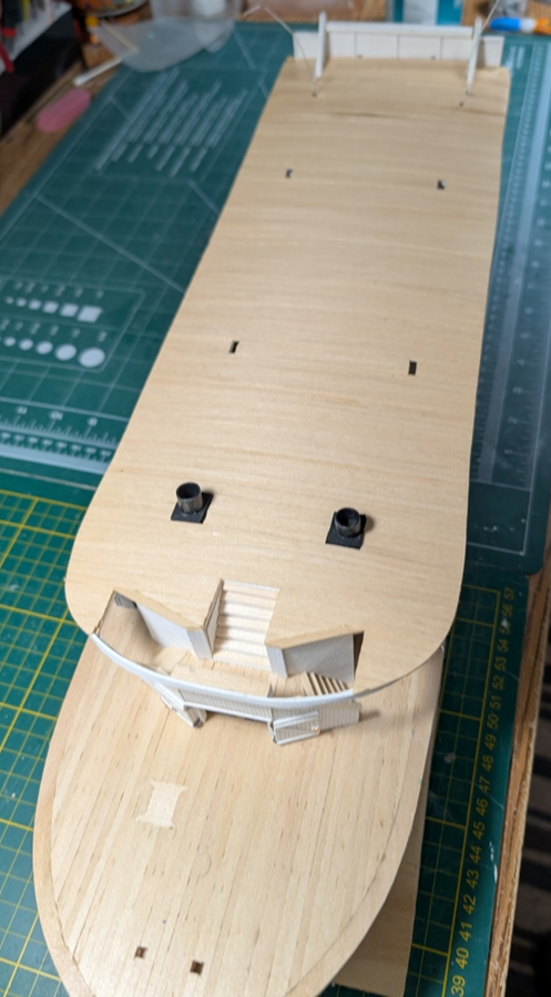
The boiler deck has been planked. My four piles (plus some more) of 1/8 by 1/32 by approximately 6-inch basswood boards were used. Time to get started on the superstructure: saloons, staterooms, galley, &c.
-
Keith, Thanks for your kind words. Love your build but the scale is unbelievable. I wish I had your patience. John, Thanks from down under. It is taking me longer as our summer & fall are busy on "other duties as assigned" but I hope to be able to dedicate more time to the boat in the next few months. LJP
-
The carlines are done and now it is time to plank the boiler deck. Surprisingly it was not the carlines which took the time but all of the other little piddly stuff: the two bells, the speaking tube, steering ropes, and a bilge pump. Several water pipes were also added. Most of this will never be seen unless it is really looked for. Still needs a bunch of cleanups before the next step can start. Note the four little piles of deck boards needed for the next step.
-
Keith, Thanks for the support. It is coming along with lots more to do. Cathead, Thanks much. I am trying to provide better views. There are lots of detail that simply get buried because of my picture angles. LJP
-
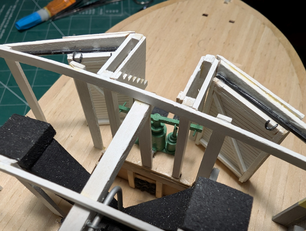
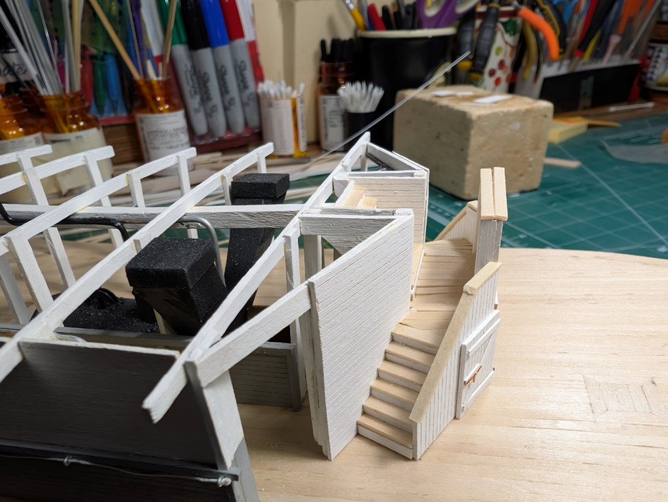
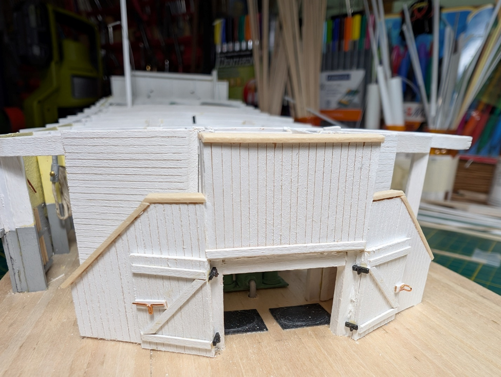
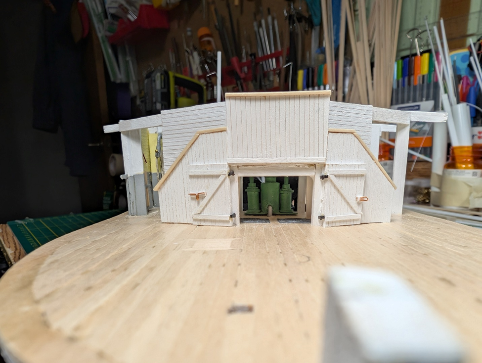
The stairs are now completed. JHC had a very utilitarian set of stairs. Many of the other early steamboats had a wonderful rounded double stair with an arched entrance underneath. JHC was simply squared off and angled. Early construction shows the sliding doors from the inside of the boiler room. I needed to repair one of the door slides which I had knocked off. The stairs stringers were cut to an 8-inch rise. A tread was then added along with a riser. The arrangement for the stairs was a short central stair to a landing and then a short course of stairs to either side. Two frontal views. The first shows an up close with the access doors to the coal chutes. The second view is a front on with a view through the access doors. The green hand pump is in the background. Time now to complete the rest of the underside of the boiler deck. Before I can add the carlines, I need to add both bells, the speaking tube, steering ropes and a bilge pump. I also need to complete the various water pipes. Lots of little odds and ends.
-
Glad to hear the good news about your health. That is the most important thing. That said, I love that you choose topics that are more unique. And in the scale that you use is unbelievable. Take care, LJP
- 457 replies
-
- 4
-
-
-
- sternwheeler
- Hard Coal Navy
- (and 1 more)
-
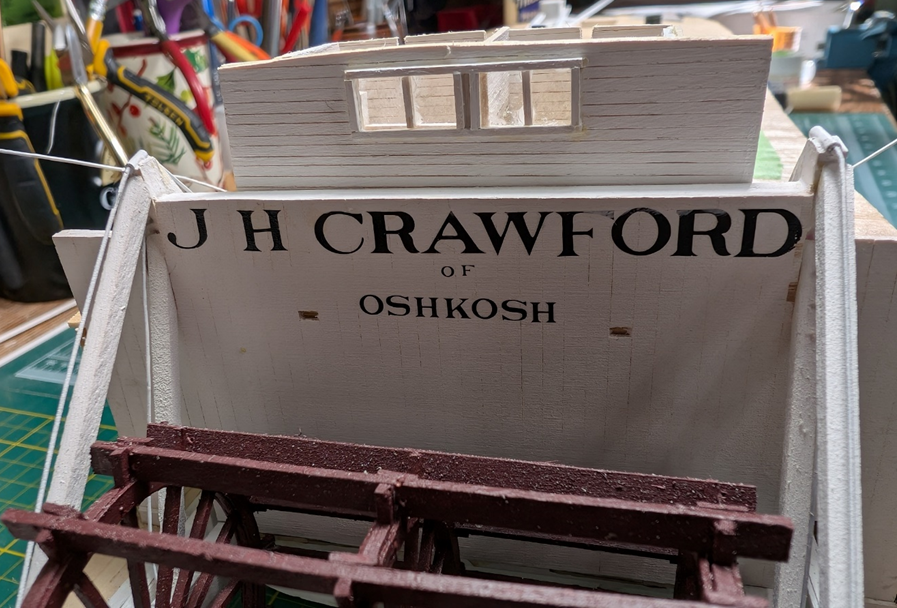
Had some time to spend on the model. Quickly installed the boiler panel. The bull rails were added. The forward one could be opened. I used Bates’ method where the rails could be inserted onto hooks. I also added the canvas coverings above the rails. Apparently, this was a common practice for passengers due to weather. Lastly, I included a gangplank. The gangplank was used where a finished dock was not available. Long and narrow, it was prone to accidents according to newspaper articles. There were several references to people falling in, women in hoop skirts, and a boy who broke his arm and sued the boat. Now I can get started on the stairs.