HOLIDAY DONATION DRIVE - SUPPORT MSW - DO YOUR PART TO KEEP THIS GREAT FORUM GOING! (Only 68 donations so far out of 49,000 members - Can we at least get 100? C'mon guys!)
×

LJP
-
Posts
159 -
Joined
-
Last visited
Content Type
Profiles
Forums
Gallery
Events
Everything posted by LJP
-
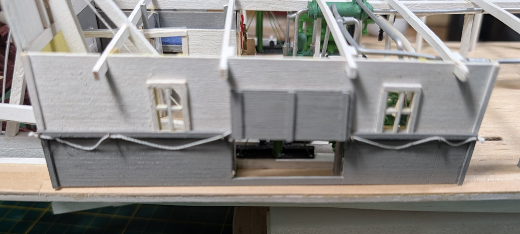
 I completed the half of the panel entrance into the engine room and the single sliding door. Initially I thought that I could cement the hog chains and the stern wheel chains at a later point in construction. But I found out that would not work. So, I had to affix that panel and the starboard engine panel. The hog chain braces are still loose and will be cemented in at a later point in construction. Next steps will be working on the bow hog chains, affixing the boiler room panel and then the bull rails. Hopefully after that I can start on the stairs. But the way I keep changing the sequence once I get started, who knows what will be next.
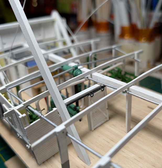
-
Sorry about the delay, but I have been away. JacquesCousteau, Thanks much! I have gotten much better but will continue to improve my skills. This is in no small part to all of the information provided on MSW. The insights are invaluable. John, Still have much to do in the engine room. It continues to amaze me how they got all that stuff in such a small area. LJP
-
Hi John, Thanks much. II know my time working on the model has really been in fits and starts. It will continue to be sporadic in the near future. I have completed the engine room panel. As mentioned earlier, I will only complete an engine room panel on the starboard side and leave the port side off to allow better viewing of the engine room itself. This also means I will only complete half of the panel entrance into the engine room, and only a single sliding door. For the engine room “glass” for the windows, I used mica. My thanks to Roger Pellett & wefalck for their recommendations and discussion of the same in Cathead’s Peerless build. The thickness is much more to scale, and the imperfections in the mica replicate the imperfections in early glass windows. For the grids, I was able to find 1/32 x 1/32 strips, but I no longer remember where I got them from. The interior view is a bit more busy with all of the engine room detail. I still need to do lots here: more pipes, bells, some machinery and all of the boiler room carlines. I may do the stairs first and then the carlines as this will make piping placement much easier.
-
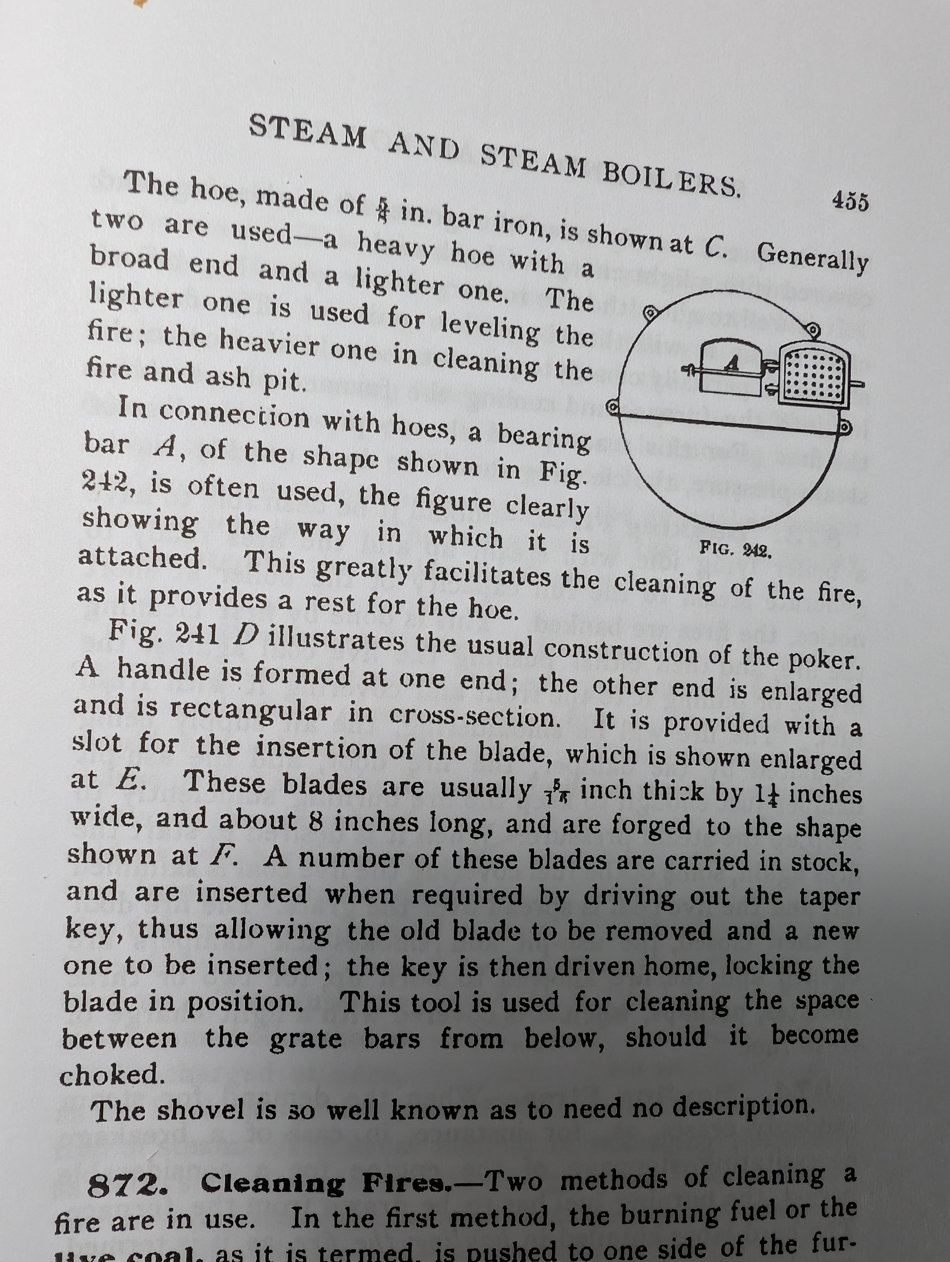
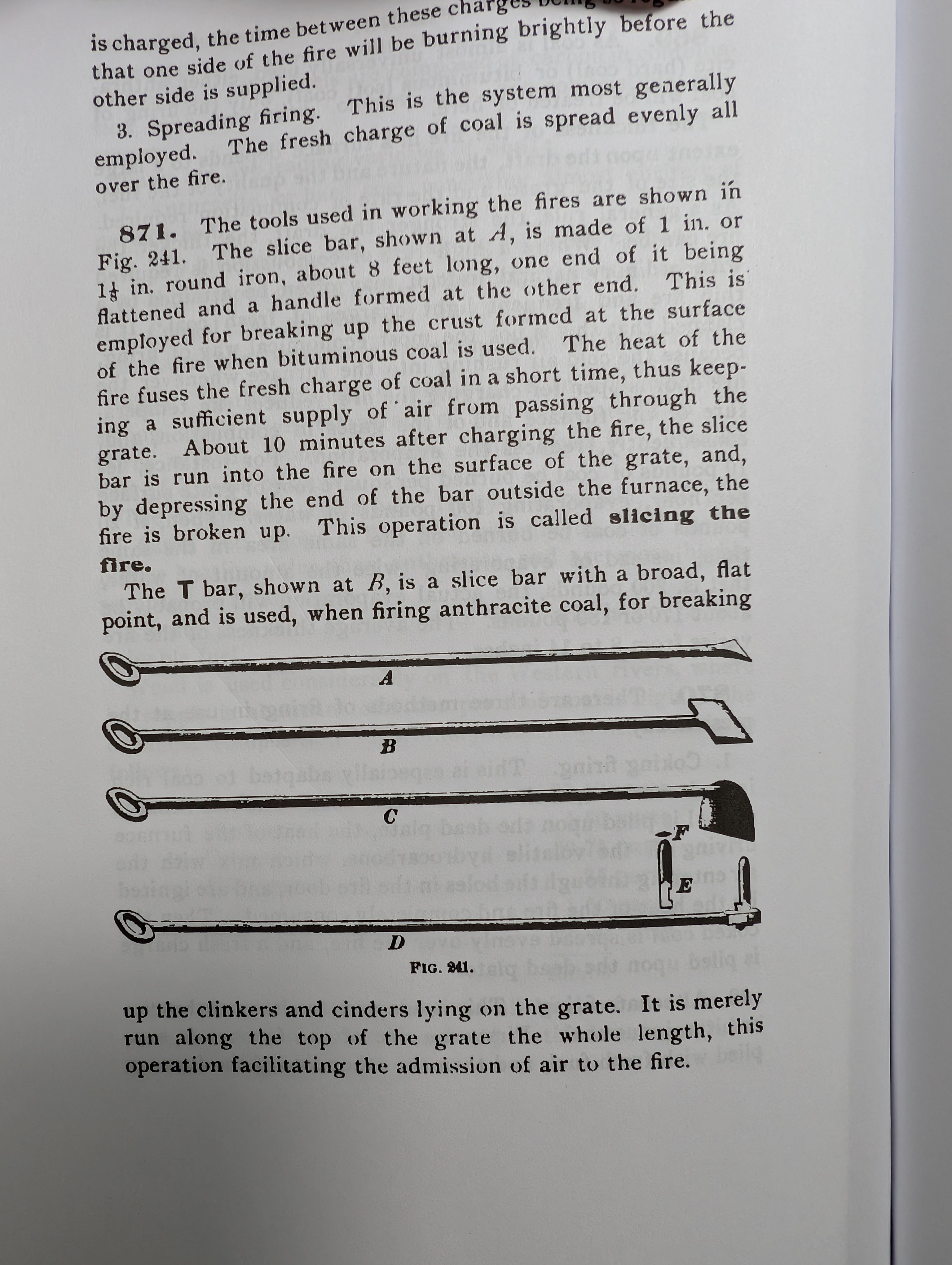
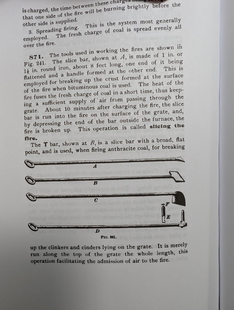
Keith, Thanks much for your praise! Really appreciate it! Cathead, Same question I had: how would these work in a boiler pit? My distance between the boiler and coal shoot is 6 feet. I actually used one of the tools (the "D" - see below) and it works if you start in the corner of the boiler pit. And a bit obsessive on my part... Not ideal but workable. This is where I got my info: Marine Boilers; Marine Engines; Western River Steamboats - International Library of Technology. (1902) Probably way too much information but hope this helps. LJP

-
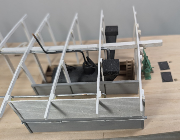
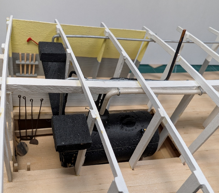
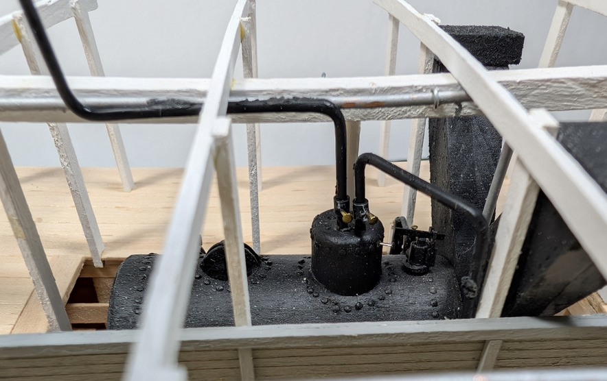
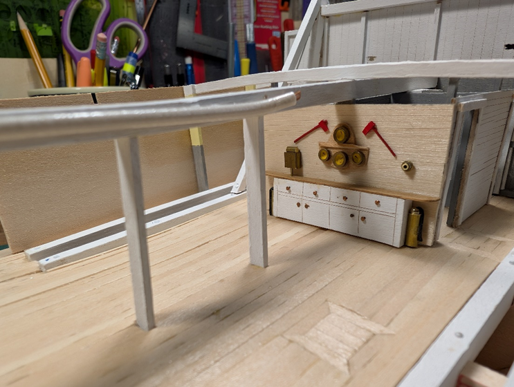
I have been working on the boiler room. The outside panel is simple. The hand ropes are the only detail on the outside. Not certain what it is called, but on the main deck, a panel was added to keep people from falling into the pit. On the inside, there is the handles for the capstan and the fire hose. Although the capstan was steam powered, there seems to have been a habit of still including manual handles “just in case”. The panel is still removable and will not be cemented in until after the hog chains are finally set when the hurricane deck is in place. Lots of little (time consuming) details have been added. In the boiler pit, a coal shovel and the four firebox tools were made. Period publications listed the tools at eight feet tall - probably long enough to both stay away from a hot fire box but also to keep the handles cooler. On the opposite side is the ladder into the pit. The steam dome had several additions. Piping to the capstan, and the radiators in the men’s smoker and the pilothouse were added. Other stuff like finishing the water piping and spent steam vent to the chimney were also built. Now I would like to finish up the engine room. Again, sorry for the delays but life has gotten in the way.
-
Hi Keith & John, Thanks for the comments! Life has gotten in the way and I have not been able to dedicate much time to the model. It may be awhile before I can again, but I will sneak in time when available. Take care, LJP
-
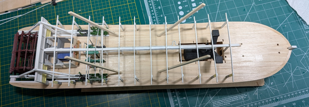
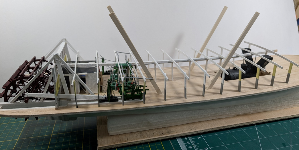
I have completed the stationeries and deck beams. Things are getting crowded. Nothing too exciting but now it is time for lots more piping and panels. The hog chain braces are only set in temporarily.
-
Wonderful choice of subject and a great build! How you can work on a scale this small always amazes me. Absolutely loved all the details - including the kitties. LJP
- 732 replies
-
- 3
-

-

-
- Lula
- sternwheeler
- (and 1 more)
-
Excellent news Take care and soon to be back modeling. LJP
- 732 replies
-
- 4
-
-
-
- Lula
- sternwheeler
- (and 1 more)
-
Hi John, Engine rooms are really wild. I looked at several and simply could not make heads or tails out of them. I would need a complete set of pictures, a bit of luck, and two generous fingers of Bourbon. At least the Bourbon would help... Keith, Thanks for the encouragement, Having done this, I would adjust the intake & outtake pipes on the machinery so things would line up better. I have learned a lot since my last build but still have a long way to go. Eric, I appreciate the encouragement. I have tried to find out as much as possible but there is not as much nor as concise as I had hoped. Like everything else, I would suspect once you have seen one layout, you have seen only one layout. Thanks all, LJP
-
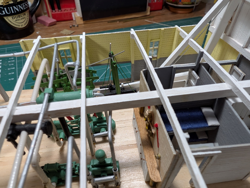
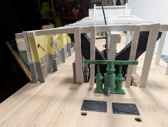
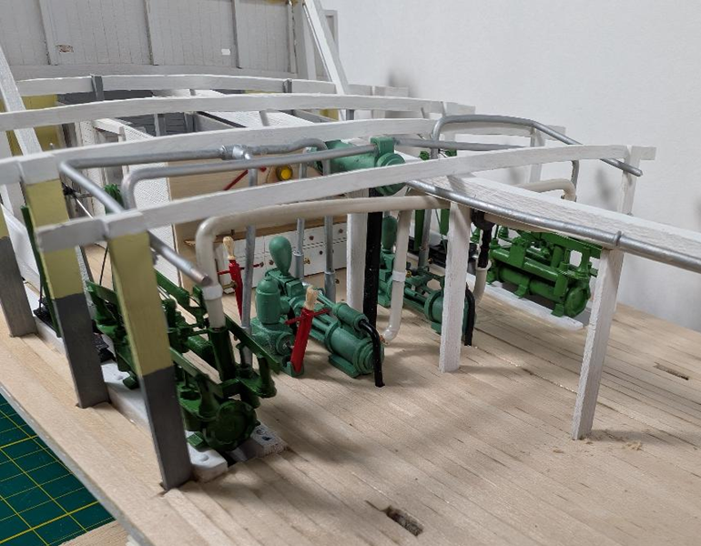
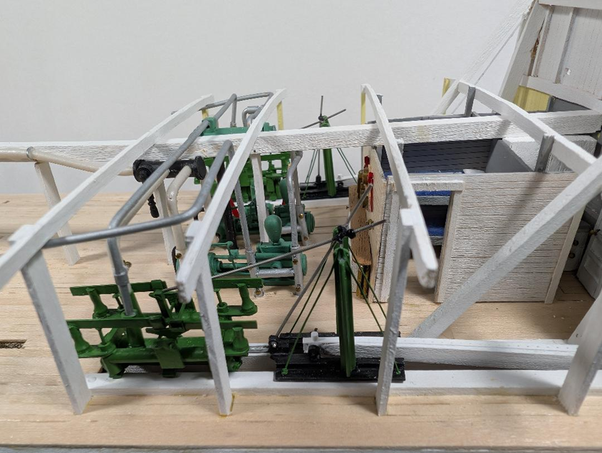
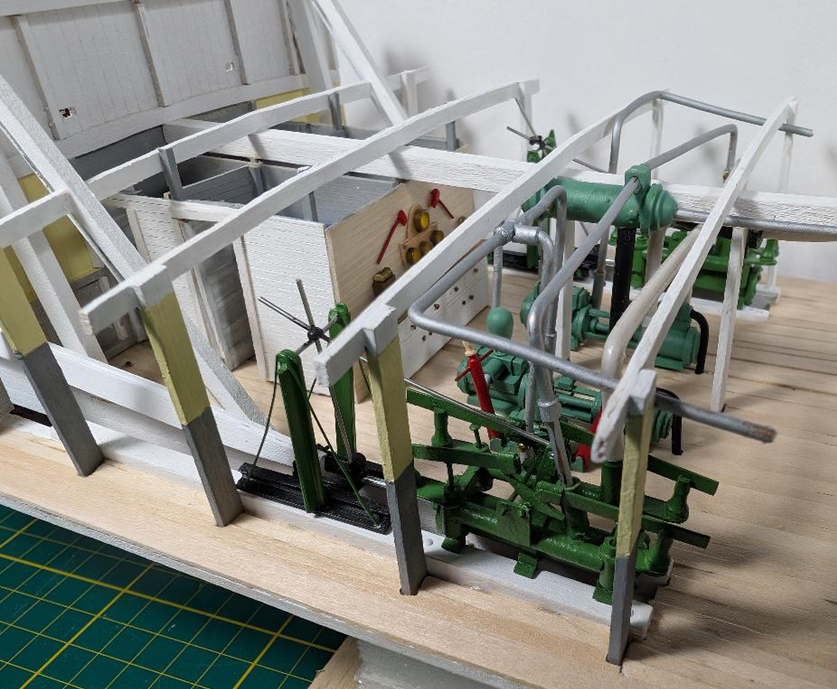
I placed the previously made machinery into the engine room: the engine assemblies, feed pumps, bilge pump and hand pump. The engines are now attached to the pitmans and the wheel. The engines and pitmans are offset by the required 90 degrees. Another view of the clutter in the engine room. I included the intake and exhaust steam lines and the water lines. I did a simplified version of both. Photos of engine rooms are best described as an explosion in a pipe factory. It is nigh impossible to follow where the pipes came from and where they went to. I did look at photos from S S Moyie and some steamboat diagrams. I found the ASME 2010 Diagram of the Power Plant of the Belle of Louisville to be the most helpful. Other diagrams which I reviewed were the American Queen, ElectircalEngineeringInfo.com and of course the ubiquitous Alan Bates EngineRoom Cyclopedium. But who knows how accurate my interpretation was. Any insight on this is greatly appreciated. On the port side photo, I included a black main valve with a lever (a/k/a throttle) for the steam line from the boiler. Steam lines would have been run to the engines. I may have made a mistake but I also included steam lines from the throttle to the feed pumps. The starboard side photo includes a feedwater heater in the engine room but not a condenser. The latter was apparently not common on smaller craft due to its size and weight. The feedwater heater was noted in JHC articles. I used a generic period pump for the model. The exhaust from the engines went to the heater. Documents noted that the exhaust from the feed pump went to the stacks to improve draft. Water went from the feed pumps to the heater and then below the main deck. The rest of the JHC exhaust was noted to have gone out the stern at the waterline. I still have a ways to go to complete this part of the model. There was a fire system with hoses that still needs to be completed. I would expect that this was river water as part of the existing feedwater system. River water was settled out and strained in the units located within the hull. I totally ignored a bilge piping system as it was below the main deck. A potable water system probably existed for the kitchen, hand wash sinks, maybe the laundry. More exotic drinking water systems included a separate tank, its own feedwater pump and a heater. Again, JHC was a small boat designed for cargo and no overnight passengers. So any portable water may have been a very simple system – maybe just a barrel or two. Next I need to put in the rest of the stationaries and the deck beams. And complete more of the piping.
-
Hi John & Rick, Thanks for your support. Some days you really need it. I hope to have an update in the next day or two. Engine room is getting closer to finished. LJP
-
Hi Cathead! Thanks for the praise!. Currently working on the engine room - the steam and water pipes are really being a challenge. LJP
-
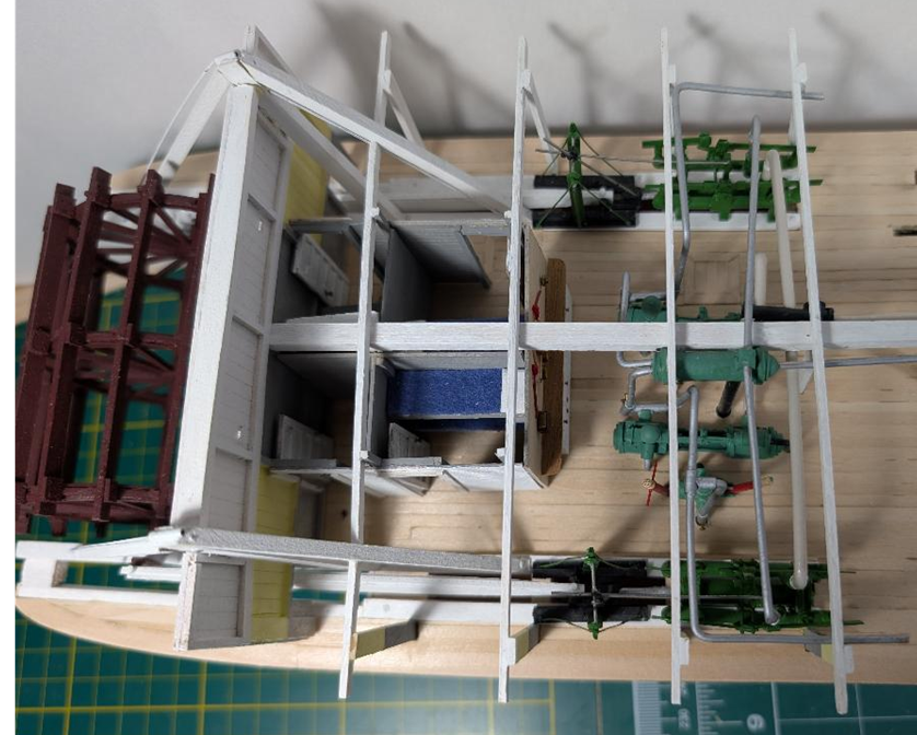
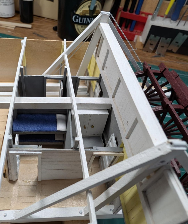
I have completed the crew quarters in the engine room. The forward two rooms are set up as double bunk bed crew quarters. The room to the right is set up as the engineer’s closet, and the one across is postal and regular storage. The panel on the back will eventually be used for the starboard engine room superstructure. I will leave the port side open for viewing. Another view but with the engine room work area & gauges. The crew quarters do not reach the full height of the boiler room stringers. This is by design. The space above was used for numerous cables, pipes, &c. Now I would like to finish the engine room: place the machinery, finish the starboard superstructure, add in some pipes and detail.
-
You are in my thoughts. Your health and your wife's welfare is what is really important. Take Care, LJP
- 732 replies
-
- 4
-
-
-
- Lula
- sternwheeler
- (and 1 more)
-
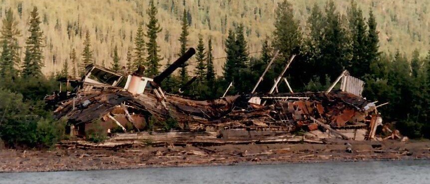
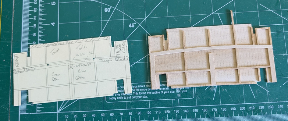
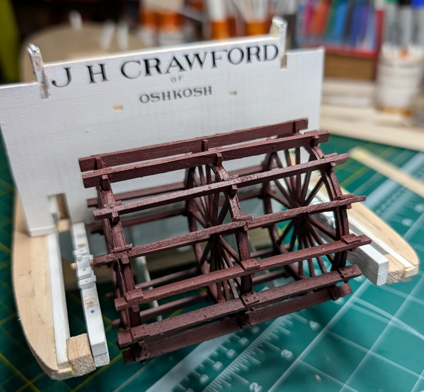
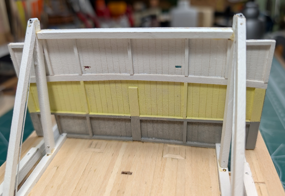
Family duties took longer than expected. The false stern panel also took longer than expected. To get the false stern panel to fit within the sternwheel braces, I needed to deconstruct part of that assembly. I prepared a cardboard mockup of what the panel would look like and then built the panel. I used dry erase lettering for the boat name and home port. The interior panel was white for the boiler deck although the panel is only currently at partial height. The main deck interior panel is painted yellow at the top and with a grey bottom. This is the colour scheme that I noted at the Dawson City boat graveyard but also what was used on S S Moyie. My intent is to leave the main deck panels off on the port boiler and engine rooms so you can see the interior boat detail. I am not certain if I will also leave the port panels off on the boiler deck to allow visual access to the saloons and staterooms. I have lots of time before that needs to be decided. Next step is to build the crew quarters in the engine room.
-
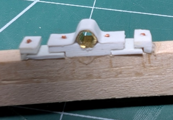
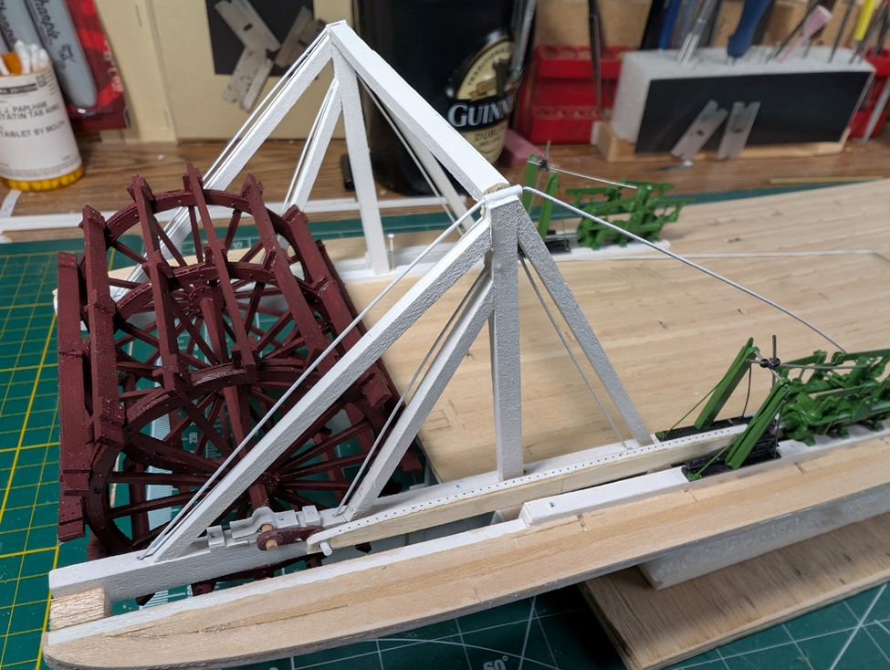
It will be hard to see when completed, but this is what the pillow block looks like. Still needs a grease cup/oiler. I tried to leave the keys where you typically would find them as they were used to tighten and true up the sternwheel. This is a temporary setup of the sternwheel with the starboard pitman connected to the crosshead by the engine. Lots still needs to be done. On this side, the engine piston is all the way forward so the crank is horizontal. The other side, when completed, the engine piston will be at exactly 50% compression- so the crank will be vertical. Again, this arrangement was used to keep the engines from locking up the sternwheel. Keith Black, I used the ArcherTransfers.com transfers that you told me about on the pitmans. These are nearly impossible to see but the rivets (sorry wefalck, not nuts & bolts!) are resin but attach just like a decal. Tiny but easy to apply. I still need to complete the port side, add the oilers, trim parts, paint, &c. I will pull this entire assembly off so I can work on the rest of the engine room first. I wanted to get this out now, although incomplete, because I have family duties that will keep me from working on the model for the next few weeks.
-
wefalck, I do not know how to even begin to describe how incredible that is! Thank you for the two links, I encourage others to view the other photos. Small wonder Bavaria is headed off to a museum. LJP
-
wefalck, In re the German gentleman, I am not certain if I am more amazed that he made several feathered sidewheels in brass, or that he did in in 1:100. Incredible! Cathead, Thanks! In our model boat club, we had one member a few years ago who used CAD and a laser cutter to do the wheels. Recently, another member drew and 3-D printed the entire sternwheel for the Delta Queen. The 3-D is ridiculously detailed. LJP
-
Kurt, WOW! I cannot believe anyone would willingly make a feathered side wheel. I would love to have seen that in action! If you ever do attach it to an RC model, let me know. LJP
-
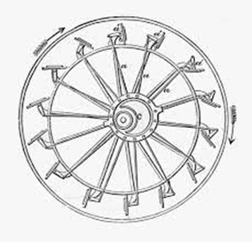
Source: WikiMedia Commons Hi Keith, Sorry that I was not clear in my definition. My concept of a feathered wheel is where the buckets would adjust as they went around. It was proposed that the buckets were more efficient in pushing the water. As you can see, this would be an absolute horror story to try and recreate in a model. LJP
-
KeithBlack, Thanks much. Like your built but the scale is something else! wefalck, I am very happy the buckets were not feathered, this was bad enough. I had seen those type buckets on sidewheelers but do not recall seeing them on sternwheelers. KeithAug, Thanks much. I have found that the research is easier than my building abilities. I have tried to make it as accurate as possible, but there is always room for interpretation and "creative license". John, I appreciate your support from Down Under. You have a beautiful country and love Sydney. LJP
-
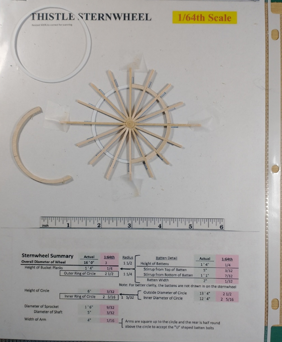
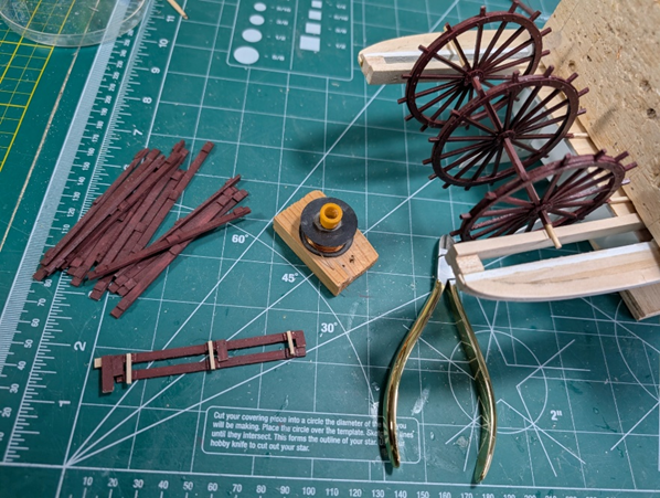
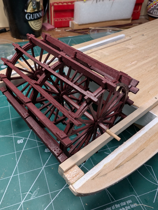
The sternwheel was constructed the same as with the Thistle. I used the same template for the paddlewheel. I inserted the template in a plastic sleeve and then taped the arms down over the flange and the circle. This is what one of the paddlewheels looks like during construction. There are lots of parts and pieces in the sternwheel construction. It is hard to see, but the shaft is K&S hexagonal brass with a small round dowel insert. And the final construct looks like this. A considerable amount of time was spent in order to get to this point. Now I need to spend time on the cylinder timbers, braces, and pillow blocks before I can add the cranks to the pitman bar. After I complete that I will set it aside. I want to work on the engine room before I affix the cylinder timbers and sternwheel assembly.
-
In re stoves. Later steamboats , like S. S. Moyie, had radiators in the pilot house. Earlier versions had steam pipes that went back and forth to achieve the same result. You can also look for a chimney in the pilot house roof. Love your build, LJP
- 732 replies
-
- 6
-
-
-
- Lula
- sternwheeler
- (and 1 more)