HOLIDAY DONATION DRIVE - SUPPORT MSW - DO YOUR PART TO KEEP THIS GREAT FORUM GOING! (Only 68 donations so far out of 49,000 members - Can we at least get 100? C'mon guys!)
×

LJP
-
Posts
159 -
Joined
-
Last visited
Content Type
Profiles
Forums
Gallery
Events
Everything posted by LJP
-
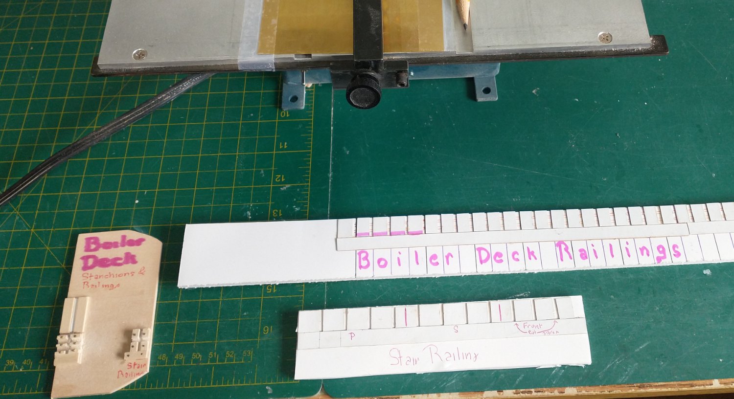
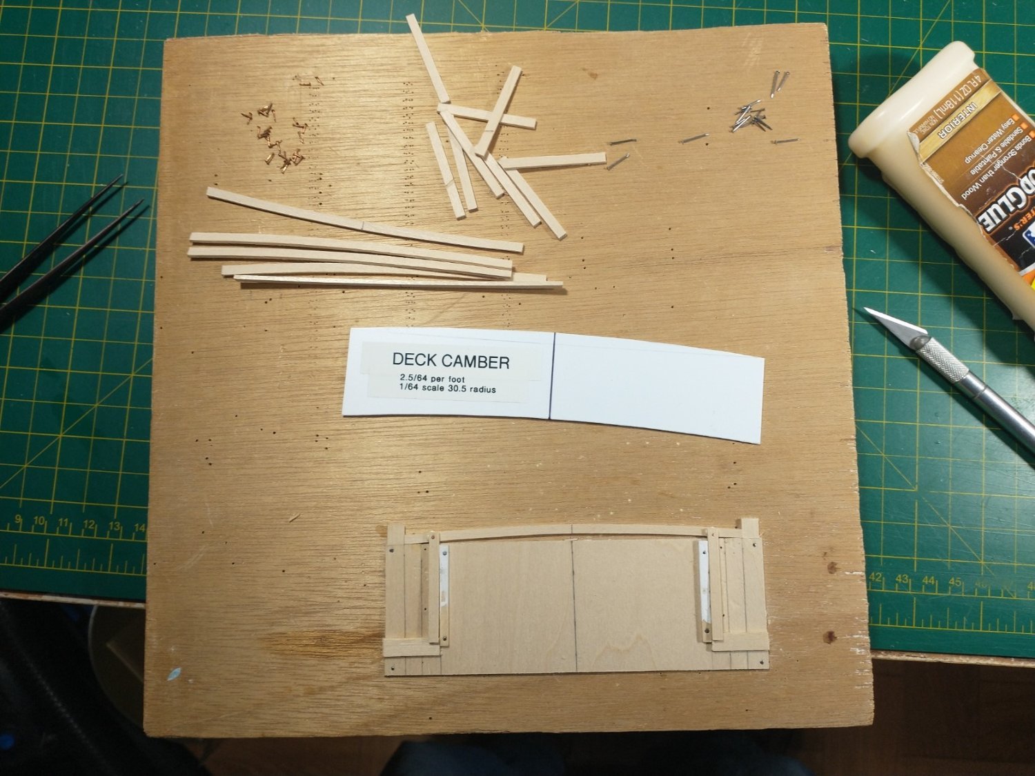
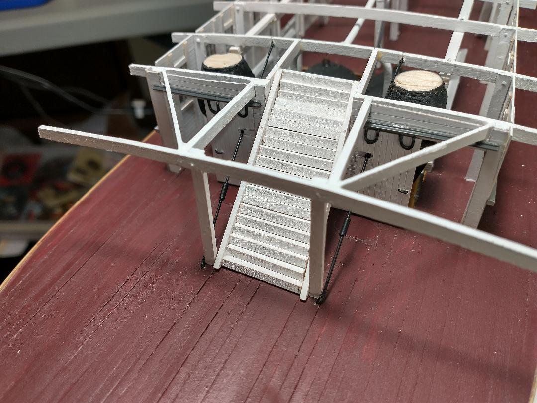
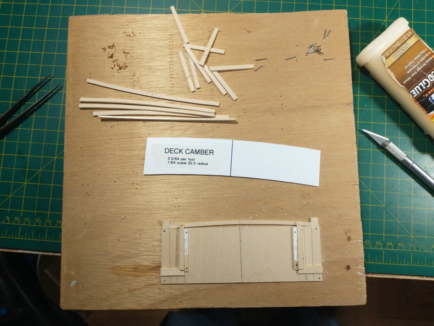
 Hi Eric! Thanks much. This is what I did to build them. I know there are better methods, but it worked for me. Thistle's railings were much simpler than much of the bric-a-brac on larger steamboats. Photos on my first post show how straightforward it truly was. I used the jig and templates below to build the railings. The jig on the lower left was used to file cutouts for the railings on the 1/16" square stock used for the spindles and stanchions. It also provided the correct height for both the spindles and stanchions. The spindles and stanchions were then inserted into the Boiler Deck & Stair Railings templates. The lower railings were 1/16" square stock cut down on my Jarmac to 1/32 x 1/16 and then inserted into the filed cutouts. Easy. The top rail was 1/16 x 1/8 that had rounded edges and was finished with boiled linseed oil. It fit across the top of the template. Again easy. The rounded section at the bow required bending over templates and hand fitting. Took longer but still came out okay. Again, there are many ways to achieve this but it worked well for me. Thanx again, LJP
-
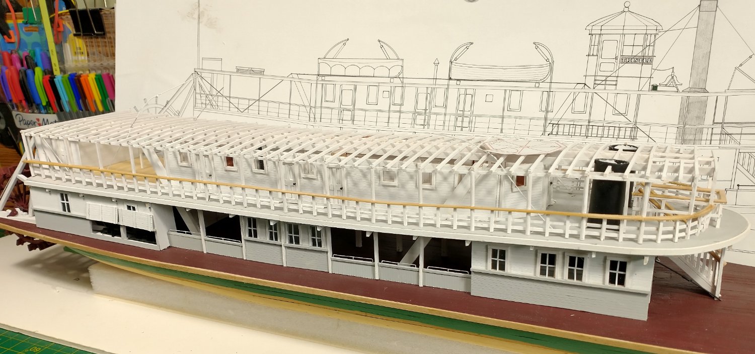
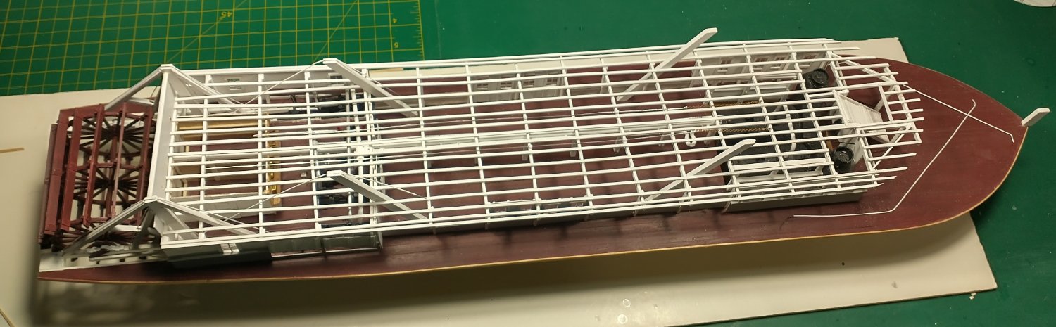
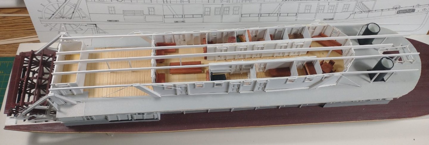
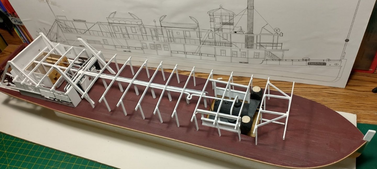
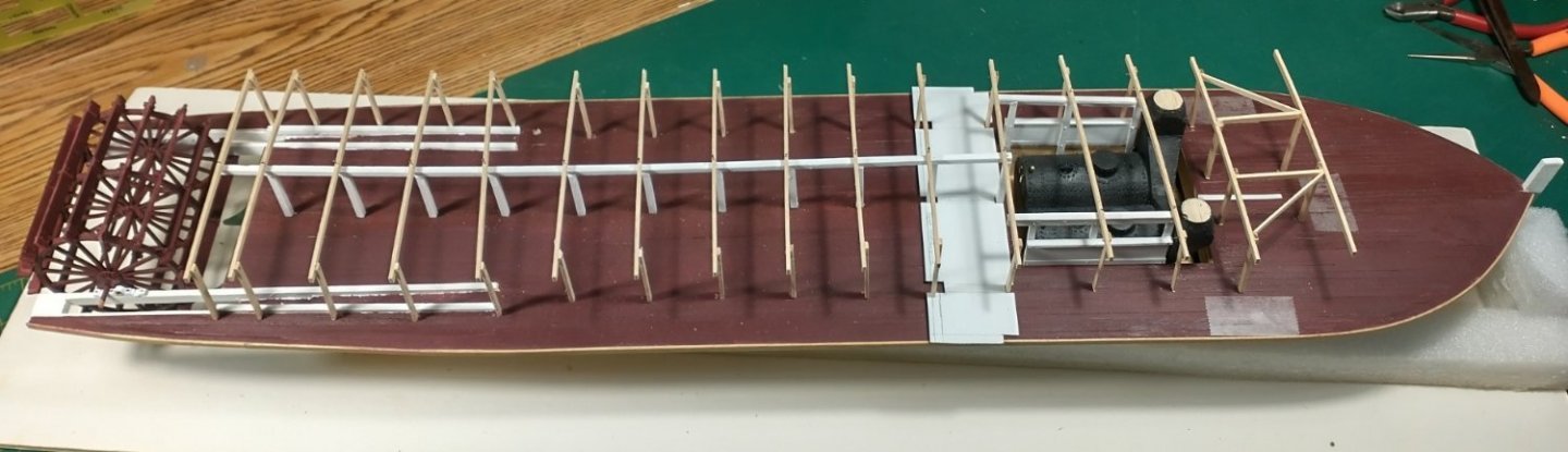
I have completed the railings and the transverse carlings. Jigs and templates made this process a whole lot easier. Thistle is actually and finally starting to look like a sternwheeler. My next step will be to add the hurricane deck. The paper cutout on the deck is for the pilothouse. The pilothouse build will really be interesting. The pilothouse roof actually had two different styles. I will use the post-1901 style as shown on the plan in the background as this was the one in use for my time period. The earlier version had a lip at the bottom of the roof. One of my challenges is that as I look at my Thistle photos for the umpteenth time, or as I get new ones off of eBay, &c., new details or changes are noted. The parts and pieces will be "circa" historically accurate but will be an amalgamation of several different photos and years. Part of the challenge is that there is no single photo that shows all of the detail needed to build the model. But I am extremely grateful that there are that many photos, unlike some sternwheelers that have a single or no photo at all.

- 105 replies
-
- 10
-

-
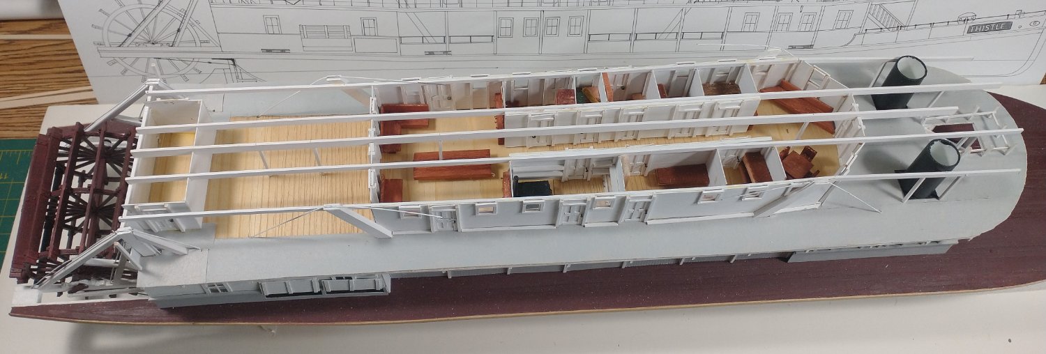
Well, I got the longitudinal beams and supports in after I did the furniture. I know - you will never be able to see some of the furniture at all and most others will be a restricted view at best. But I know it is there and it continues to be good practice on some out of practice old fingers. Railings are next. I have started on a few jigs for the railings. I will do the railings in sections. I will hold off on the boiler deck ladders (added due to Federal safety regulations after the General Slocum disaster) until further along when I start doing all of the little odds and ends.
- 105 replies
-
- 14
-
-
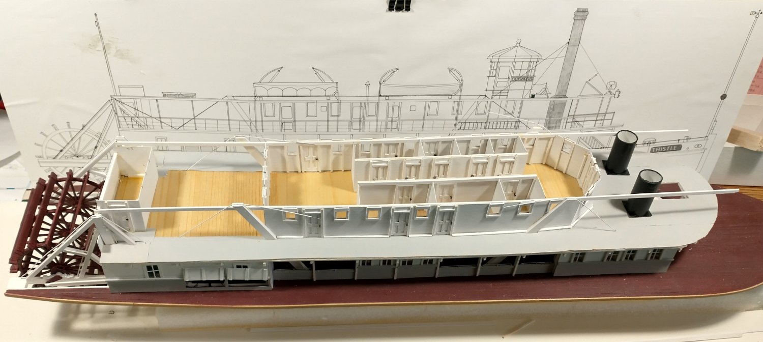
I completed the boiler deck structures. I scored all of the planks horizontally. This is how the Steamboat House at Marble Park in Winneconne was constructed. S S Moyie in Kaslo, B.C. was much different: the outward panel was horizontal, the inboard panel was vertical and the two side panels were diagonal. The diagonal panels were probably much more structurally sound, but the Steamboat House is more region specific. I know no one will probably ever see the interior panels that I put in, but I know that it is there. I know what some of the rooms were: men's and women's saloons fore and aft, galley, and staterooms for captain, cook, and engineer. I used the remaining space for extra staterooms, pursers' office, and freight office. Now I need to build some furniture for the rooms. After that, I can affix the stacks (whatever the oversized metal protection is called) and add the longitudinal beams. The boiler deck will still take some time to complete as the as transverse carlings need to be added, railings and stanchions, stair rails, etc.

- 105 replies
-
- 14
-
-

-
Dan, Sorry to be really late to the game here as I recently found your article in the Spring 2022 Journal. Your whaleback is exceptional. The last surviving whaleback, the Meteor, is now a museum ship in the Superior, Wisconsin harbour. I had an opportunity to tour it several years ago. It had been modified over the years but the basic form is still apparent. Between the low freeboard and the crews quarters, it must have been a horrible boat for the crew to ship out in. Again, great model that does whalebacks proud.
- 33 replies
-
- 2
-
-
- James B Colgate
- whaleback
- (and 2 more)
-
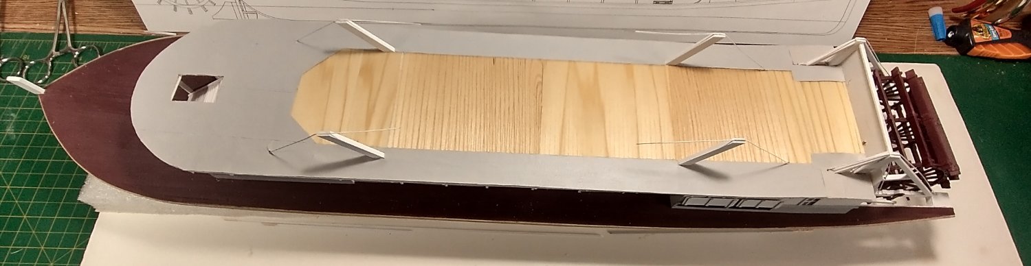
I completed the boiler deck. I used 1/64 birch plywood. Both top and bottom were scored to simulate planking. The underside is white, the top is linseed oil with a light gray painted tissue to simulate "canvas, painted and sanded". Based upon actual other steamboat photos and other models, I used the "canvas" in areas that were not covered and therefore subject to the elements. I was not certain about the covered and open area at the stern that was used as both the dining room and general passenger area. I had mentioned previously I am really not certain if this is historically accurate. I will now start on the boiler deck superstructures. The foreward part of the cabin (12 by 15) was the men's "smoker", which had a hall that connected it to the women's saloon toward the stern. The original women's saloon was also 12 by 15, but later photos indicate that it had been expanded, probably when the addition 14 feet were added to the hull. Either side of the hall included staterooms, galley and captain's quarters. The toilet at the stern may have included a wash area between the men's and women's toilets, beneath the water tank on the hurricane deck. Toilet dimensions were estimated using photo measurements. Amazingly, the last Ryan built sternwheeler, the Leander Choate (2nd) [1908 - 1922] listed the actual measurements of the toilets as 6 by 6. Strange what was or was not listed in old accounts.

- 105 replies
-
- 10
-
-
I have completed the stringers and added the steering chains. I used the layout from a Paul L. Neenah Historical Society photo as a basis. For some reason I cannot load that photo for inclusion here. The boiler deck stringers ran longitudinal (bow to stern) with the deck boards transverse (port to starboard). The two wires on the bow are the hog chains which I will add after the boiler deck is added. Now I can add the boiler deck. I need to figure out when to add the deck versus dry fitting the deck and/or building the staterooms first and then affixing the deck.

- 105 replies
-
- 13
-
-
Hi OrganizedImages! How incredible that you were able to find an article about the Thistle in your Grandmother's Autobiography! What she was referring to were the Merchant Excursions. The Excursions were subsidized by the Oshkosh merchants, hence the low 10 cents versus the normal 50 cents. The intent was to increase the Oshkosh business by poaching customers from outlying areas. Many of the other Lake Winnebago towns were included in the Excursions but obviously on different days. Many references were made of the Thistle being loaded with goods for the trip home - even the hurricane deck was used for light goods. Interestingly, some merchants of outlying areas used this as a means to supply their own stores. Other merchants, as in Fond du Lac, were not pleased and responded with their own boat and excursions - but that did not last. Still other merchants organized protests against the Oshkosh excursions - again to no avail. The Excursions ended about 1915. This was one of the reasons for scrapping the Thistle. Buying habits had changed (think Sears catalog) and the advent of interurban transportation meant one hour on a train instead of four on a boat. And the boating season, weather permitting, was April to November. This was also the advent of autos. The Sunday excursions that she mentioned were slightly different. Normal stops were Clifton, Stockbridge, Calumet Harbour & Brotherton. These were mainly for recreation, and visiting, as she mentioned. There were numerous large and small craft that conducted these. Another craft that she may have used was the B. F. Carter. I have lots more info but will stop instead of filling up these pages. Thanks Again! LJP
-
Thanks Cathead! My return took MUCH longer than expected as "life got in the way" but things are back to normal. I can finally dedicate time to the model. LJP
-
It has really been a while since I have worked on the model but summer is long over and the New Year approaches. I completed the front of the engine room. This means that I can now get started on the Boiler a/k/a Saloon a/k/a Promenade deck. I need to lay some stringers then I can get started on the planks. While maybe a not quick process I will be able to stay at this on a more dedicated basis.
- 105 replies
-
- 10
-
-
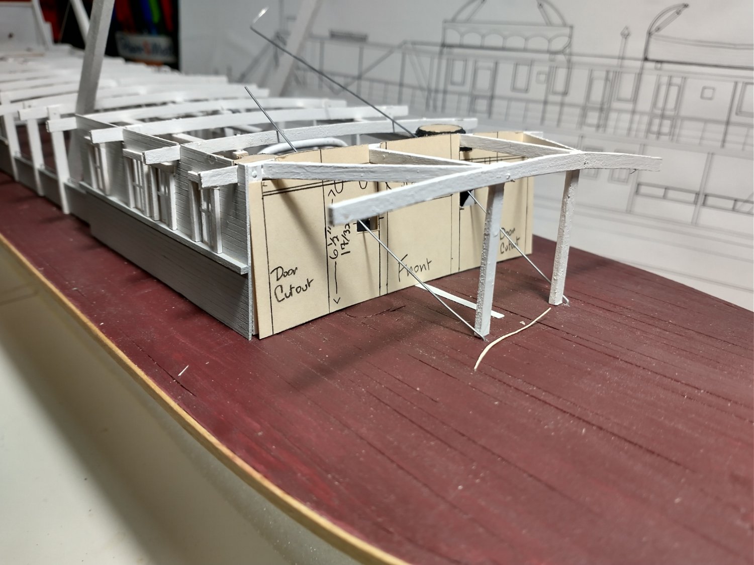
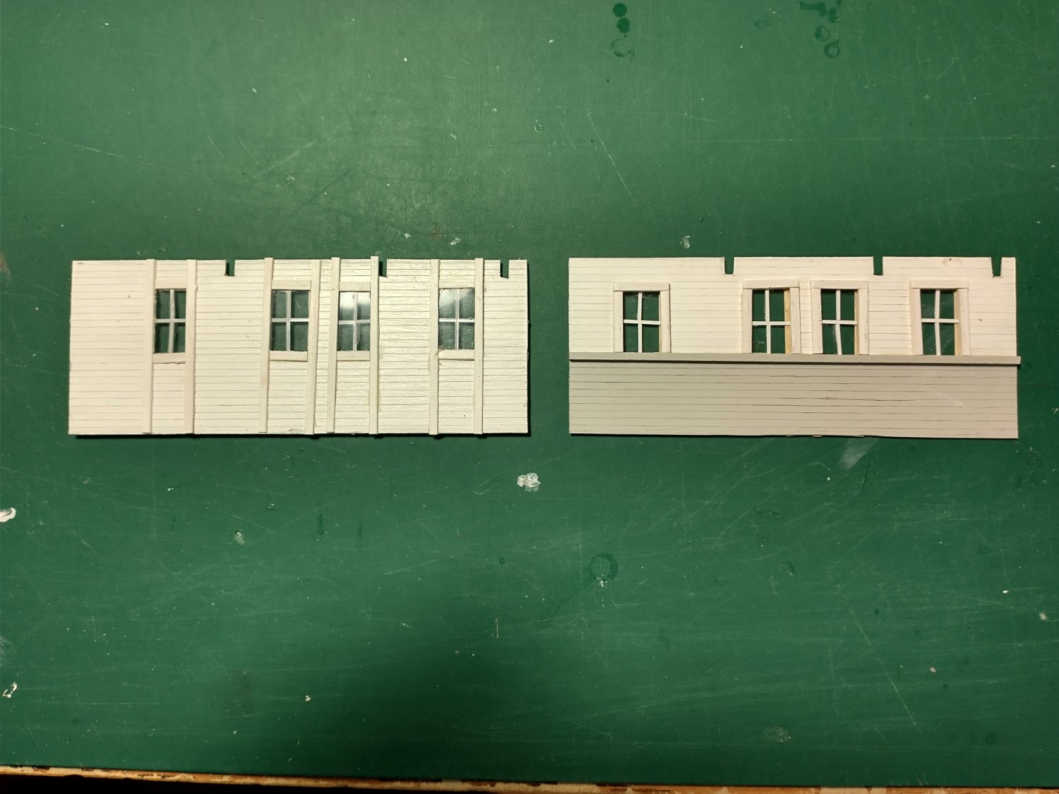
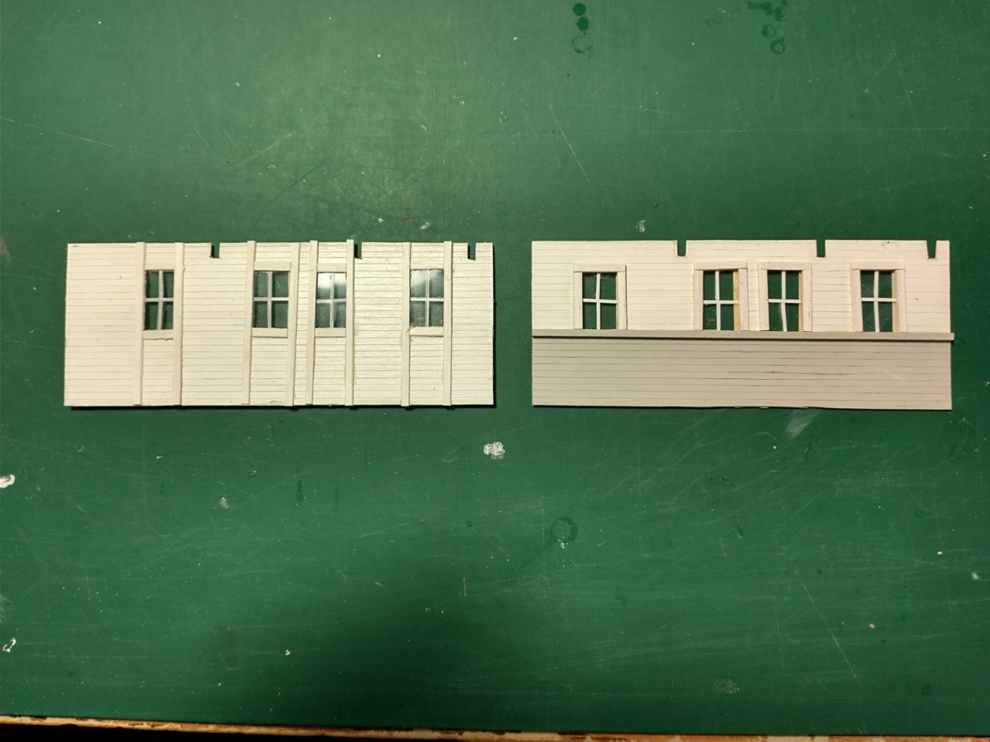
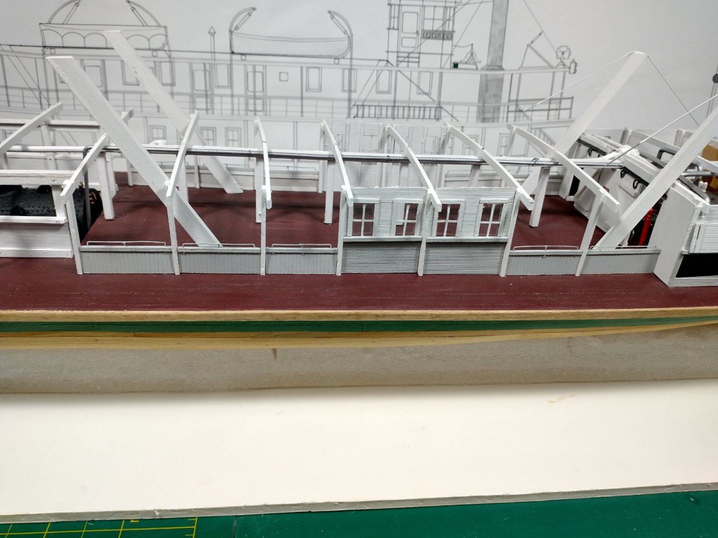
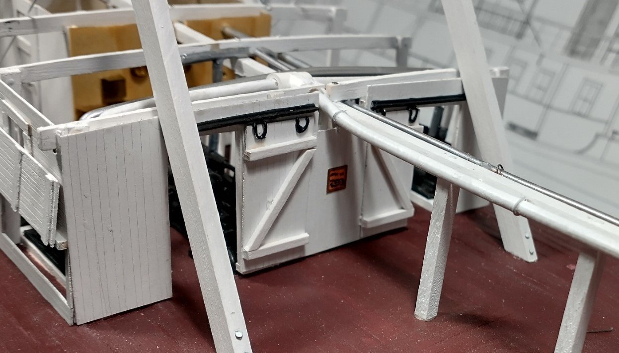
I have been gone for several weeks but am back for a few days before I am busy again. Here is my mock-up for the boiler room front panel. I will get started on the real panel in a few weeks. The chains appear to attach to a cross brace and do angle toward the keel, as Cathead had mentioned. I will attach the other boiler room panels first before I start on this panel. Below is what those side panels look like. The colour is not true, they are actually white and gray. The windows are made of cheap plastic packaging material from my junk pile and then scored for the grids. The grids are .25 x .75 mm Evergreen strips. They are secured to the clear plastic with MEK. I will not be able to work on the model for the next month or more. Wisconsin summer is too short and very busy.

-
Hi Cathead, I agree with you that it is probably attached to a structural post or cross bar. I have several other photos and the brace does angle inward - probably connects to the keel. I am creating a cardboard version of the boiler room door panel and will then take a piece of wire to try and determine where the brace could have started from, both horizontally and vertically. This brace may have been added when the J H Crawford was lengthened 14 feet and renamed Thistle. The original single boiler was replaced by two boilers at that time. Those boilers were also replaced when the single stair replaced the old-style double stair and all the other modifications were made. Photos of Thistle with the double stair obscure these braces - if in fact they were present at that time. I will see where the mock-up takes me but I will never be 100% certain.
-
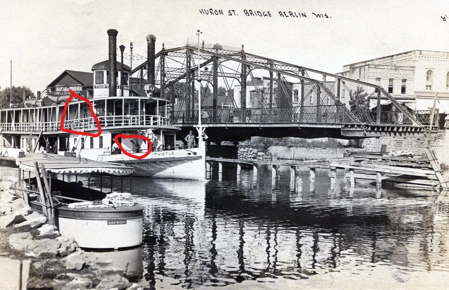
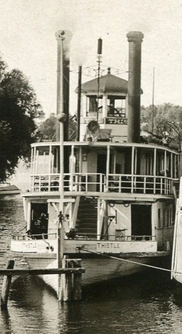
Hi Roger, Glad you like the expansion loop on the main steam line. I used insulated electrical wire to simulate the steam line so it was not difficult to replicate. Hi Cathead, thanks for your input. I hope this photo of one of my postcards helps. The red circle in the upper left is the normal hull bracing. I agree, it passes through the main deck towards the front of the boiler room. The bracing that I am confused about is in the red circle on the lower right. The brace passes through a cutout on the boiler room doors and passes through the main deck close to where the stairs start. This seems to be much heavier than the hog chains - almost like a threaded iron rod. It is hard to see in either photo, but there is a turnbuckle just in front of the door. Pure conjecture on my part, but it seems to be connected to something in front of the funnels & breeching. Thanks, LJP
-
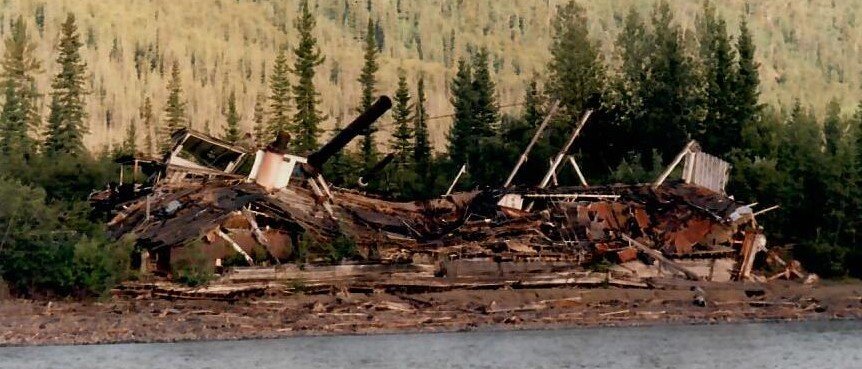
I have added the bulwarks and the mid-deck superstructure. Thistle's bulwark planking was run vertically while the superstructures were run horizontally. The mid-deck structure was an oddity that I have only found on Thistle but I am sure there were others that had them. Since it was open, I suspect it was to provide some shelter from the weather, but the bulwarks had canvas coverings that were dropped down when needed. I will now move on to the boiler enclosure. Again, since this is summer, I am less than dedicated to working on the model. But I am looking forward to making the main stairway. The hog chains that passed through the boiler room doors are a bit of a mystery to me. They are not the prominent hull bracing but seem to be some sort of boiler bracing. You can see where they went through the deck at the bow, but if they had braces to support them like the other hog chains or something else, I have no idea. Bates had something in his Cyclopedium on hog chains and braces, but nothing quite like this. D. C. Mitchell in his book showed similar chains on his drawings but they really went nowhere. This is what they looked like. If anyone has any ideas as to how this was laid out, I would appreciate it. Also note the LeFevre standing figure on the stempost. Another Thistle oddity.
-
I have really gotten very little done over the past few weeks. During our summer up here I am normally very busy and spend little time modeling. That said, this is the most recent photo. I will now finally begin on the bulwarks and main deck superstructures.
- 105 replies
-
- 10
-
-
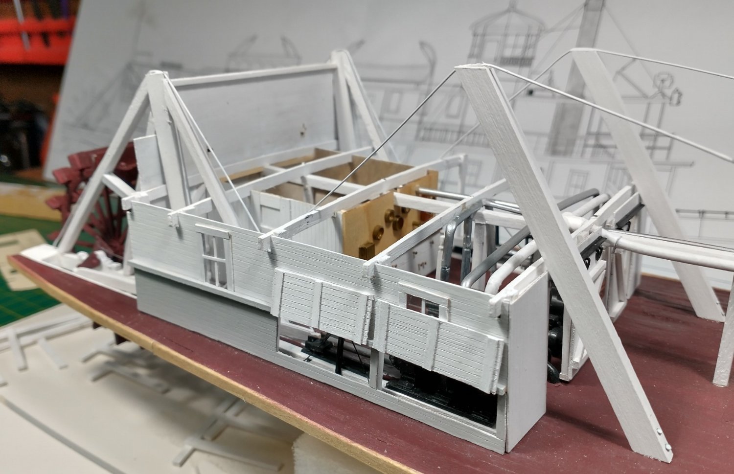
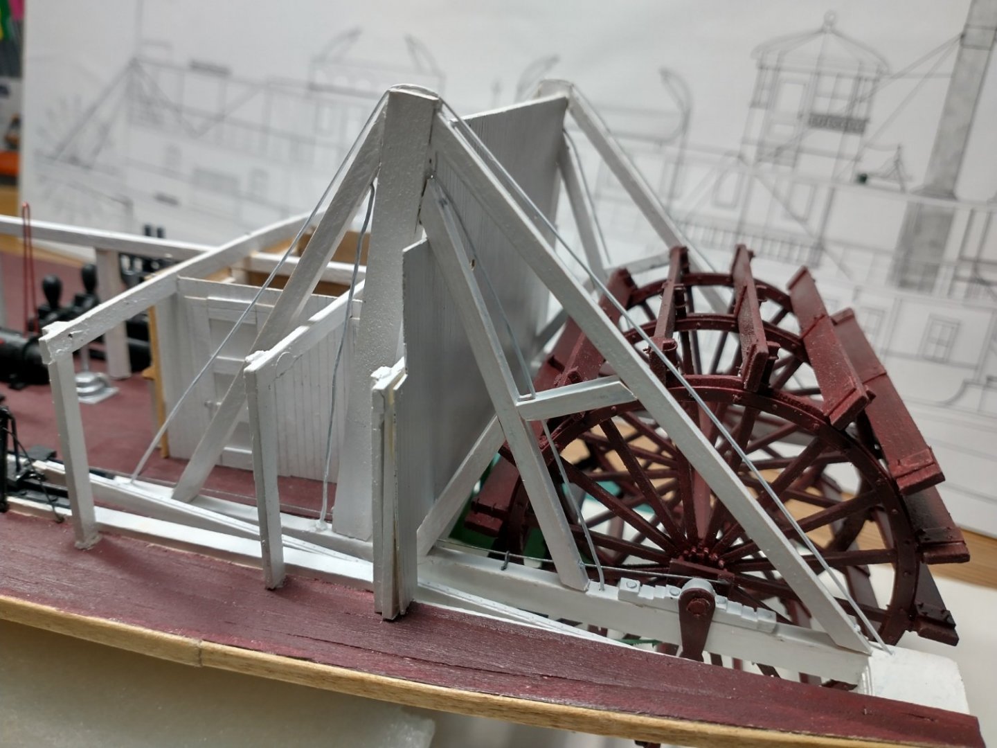
Cathead & John, thanx for the kind words! Bob and Brian, welcome aboard - I hope you enjoy the build! I finally got the stern hog chain braces and chains installed. I started the engine room superstructure and did take some "poetic license" here. I left both ventilators open so the engines can be viewed instead of where the engine ventilator was often closed. On the sliding doors, I had the Z supports on the outside to make things more interesting. Plain panels just seemed too boring. I have also added the main steam line and a return line. These included the connections to/from the engines and other machinery. I quickly discovered that the actual photos of crowded and confusing engine rooms should have warned me for what the model would be like. Placement of items in an even typical engine room is incredibly complex - even where a simplified layout like mine is used. Should I ever decide to do another steamboat, much more planning is needed here to properly place all of the machinery and lines. I will now start working toward the bow. I will place the stationaries and carlines and begin adding Thistle's unusual bulwarks.

- 105 replies
-
- 10
-
-
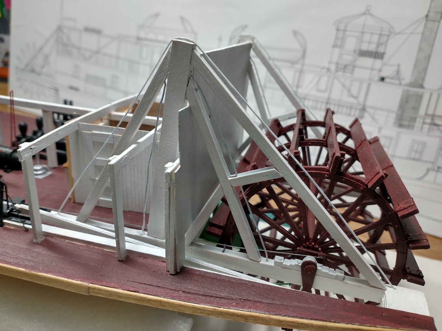
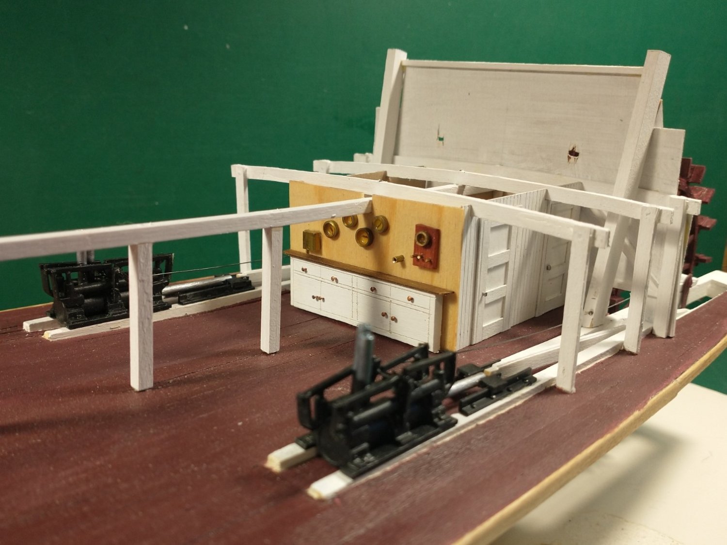
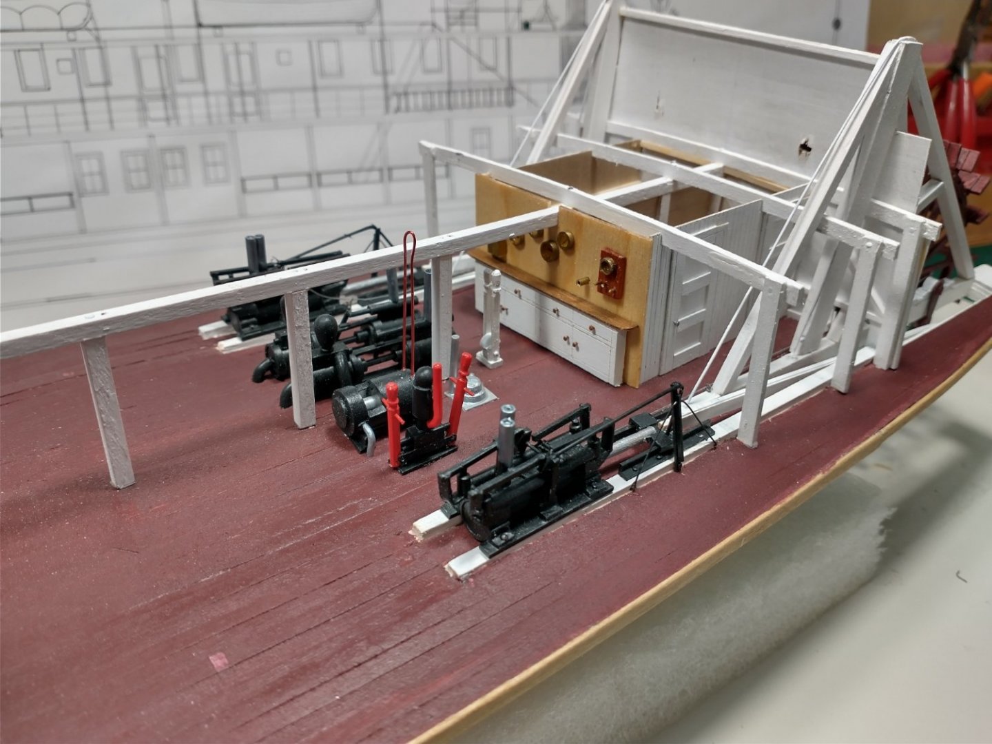
I have been busy at the stern. I completed the paddlewheel hogging chains and braces. Thistle had additional supports between the paddlewheel braces while the earlier J H Crawford did not. I still need to add the engine braces and hog chains before I can close this up. I populated the engine room. I affixed the boiler and auxiliary feed pumps and the dynamo. I also added the levers for the variable cut-offs, included the silver bilge pump and the manual red vermillion handled fire pump. I tried to match the red vermillion colours that I found on the internet but could have added even more orange to the red. Lastly, I added the engine pendulums that you could see through Thistle's ventilator doors. These looked to be similar to Rees' or California Cut-Offs but there was not clarity on the two Thistle photos that I found.
- 105 replies
-
- 15
-
-
-
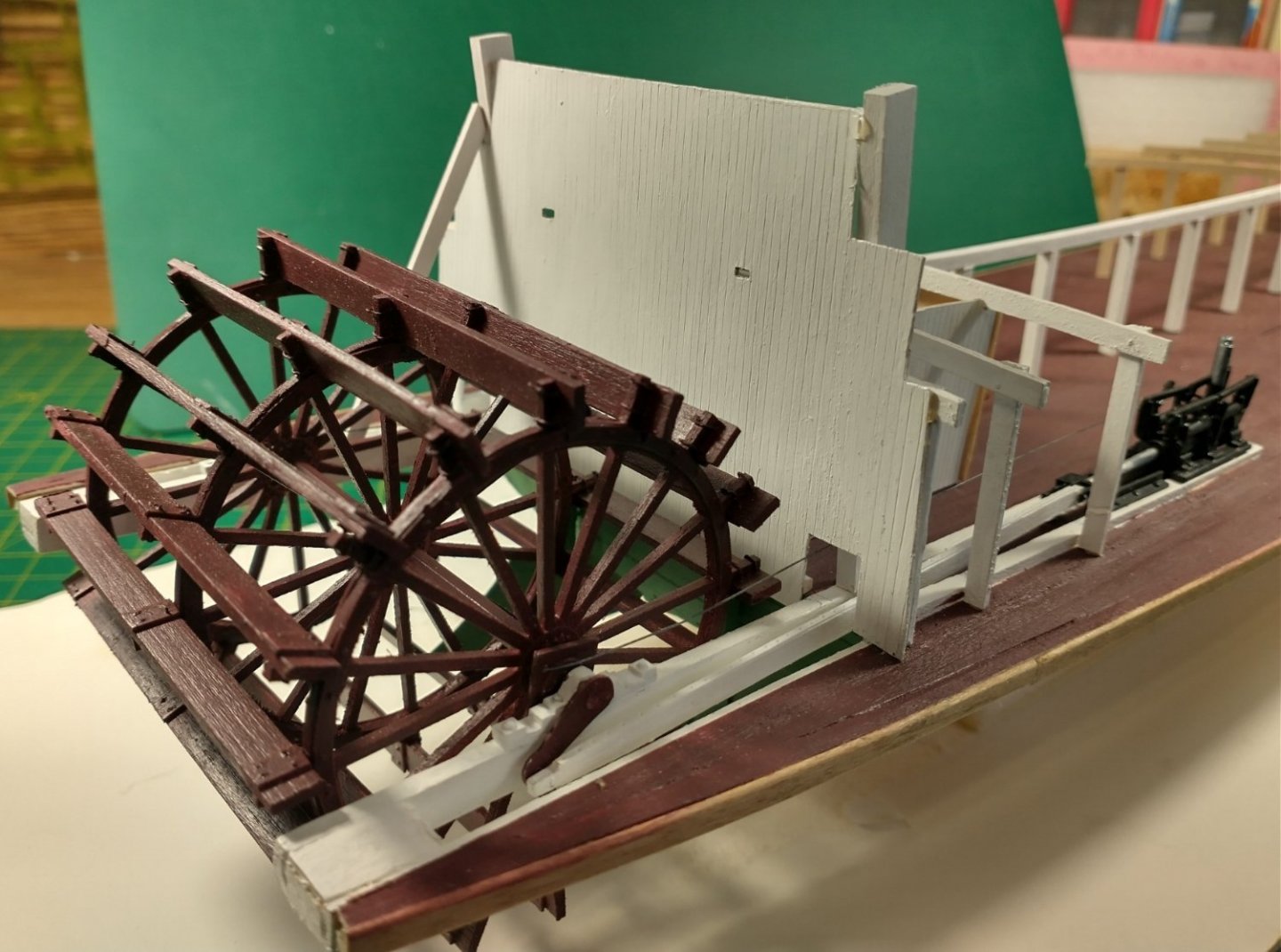
I have been busy in the engine room. Newspaper accounts indicate that Thistle had a crew cabin for the deckhands, fireman and engineer in the engine room just like Yukon steamboats. The work area with the gauges &c. follows what Moyie currently has. I used Midwest 1/64 birch plywood for the walls. A couple coats of paint and then I scribed the wood to make it look like individual planks. The engine room still has a long way to go with additional equipment and the overhead piping. I also need to add the stern brace and chains and the steering "rope" before enclosing the engine room and adding the boiler a/k/a saloon a/k/a promenade deck. Local period newspaper accounts referred to the boiler deck as either the promenade or saloon deck - never the boiler deck. I added the stern panel and affixed the sternwheel before I could proceed further. That single stern panel was the height of the main deck (8') and the better part of the promenade deck (7') except the top part of the toilet area will still be added. My next steps will include adding the rest of the paddlewheel braces and hog chains. I will use dry transfer lettering for all of Thistle's nameplates at the end of the build.

- 105 replies
-
- 15
-
-
I have started on the main deck framing. I used the attached jig and template to be consistent on the frames. In real life, there were 7' tall and most were 7' apart. and this is what it looks like when the unpainted/unfinished frames are loosely attached. I have a white spacing jig right behind the boiler pit. I will remove the frames and get started in the numerous main deck details before I go any further with the framing.
- 105 replies
-
- 11
-
-

-
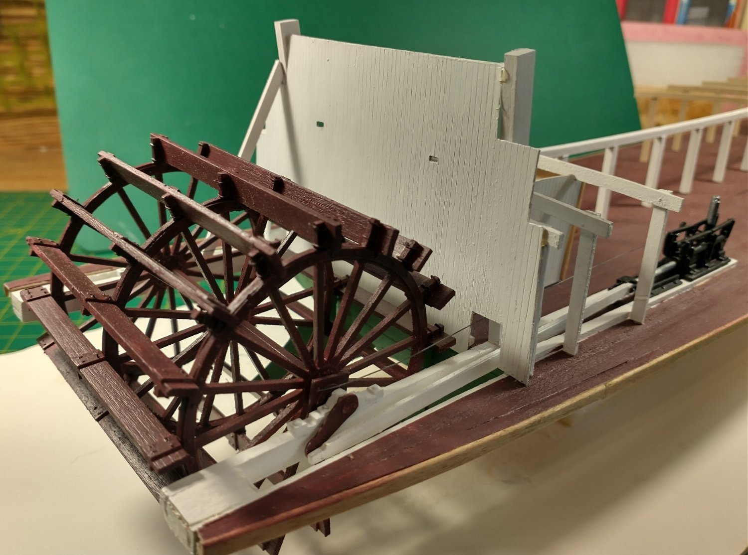
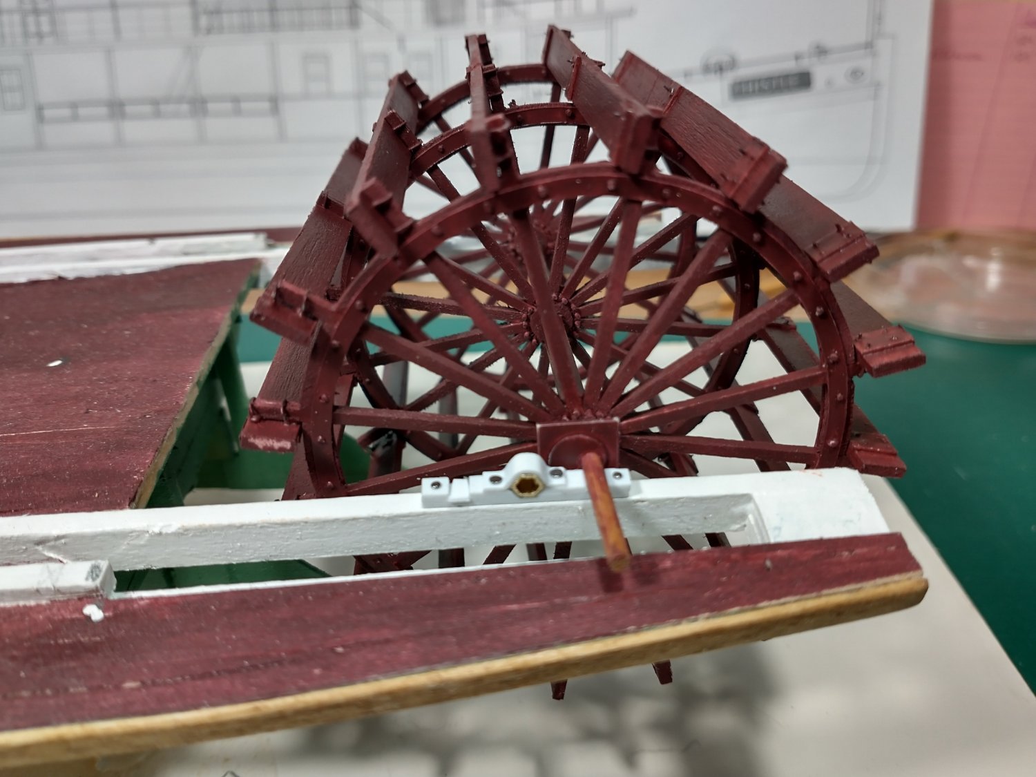
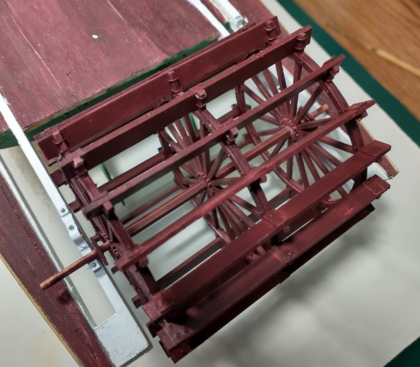
Thanks, John, for your continued support. Mark, Thanks for your comments. I have period specific "colourized" steamboat photos with a red orange that I will try when I get to paint the fire pumps and possibly the pipes. Otherwise, I really have no idea what colour they were. I have preliminarily completed the sternwheel. I need to adjust the shaft length and do paint and other touch-up before it is complete. For the time being, I just laid it on the pillow blocks. The square on the shaft is an eccentric. Bates and others had two different type eccentrics. I went with the type that had an offset circle and a strap. I will attach the rods to them later. A top-down view of the same. After this is finished, I will probably start on the stationaries and the hog braces.


- 105 replies
-
- 14
-
-
Steamboats and other rivercraft - general discussion
LJP replied to Cathead's topic in Nautical/Naval History
Cathead, I appreciate that you let us know about the presentation. I did find it enjoyable even if it was not as in-depth as I had hoped. I liked the photos and it gave me some more ideas to research. Thanks again! LJP- 281 replies
-
- 3
-
-
- Steamboats
- riverboats
- (and 3 more)
-
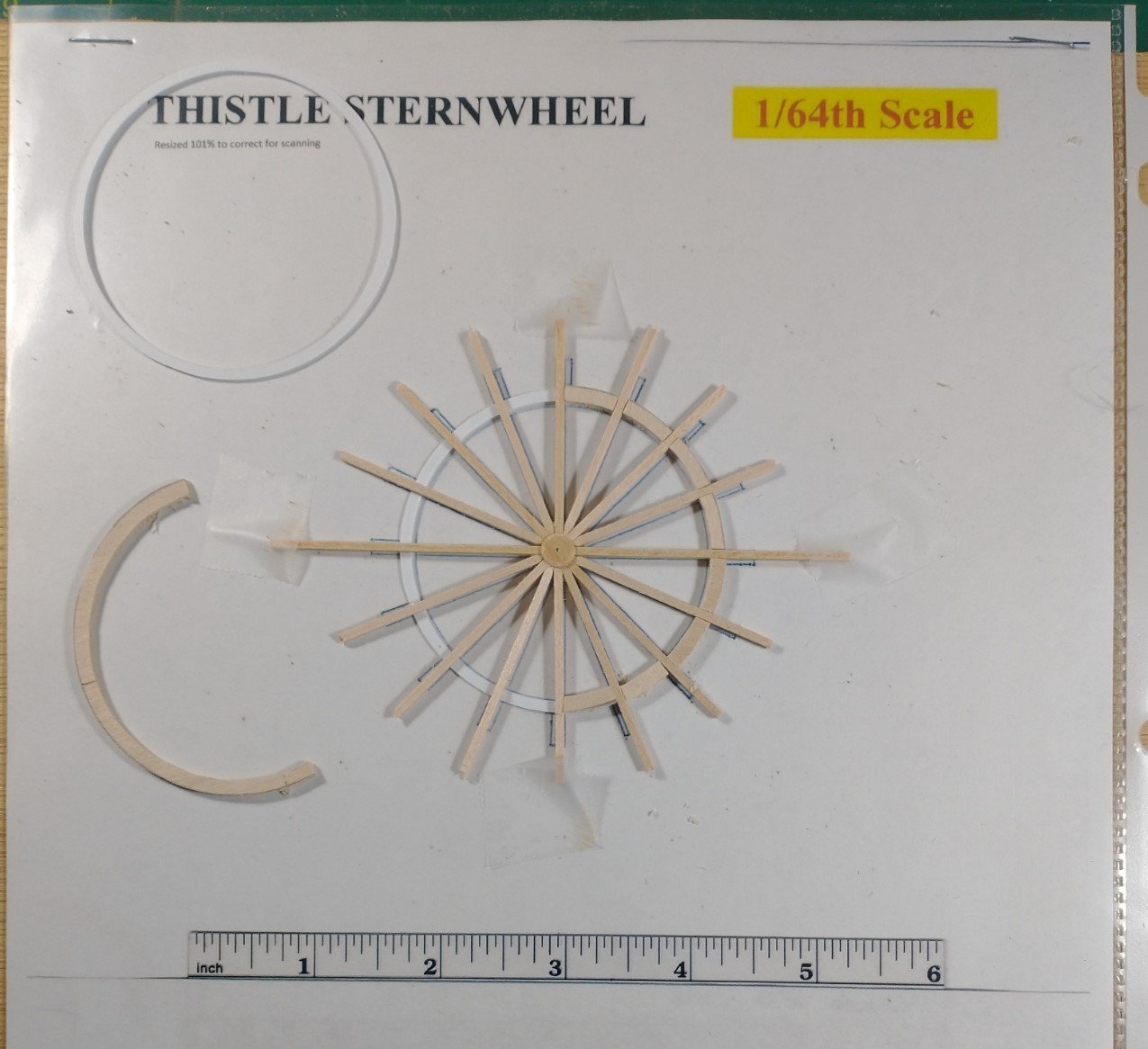
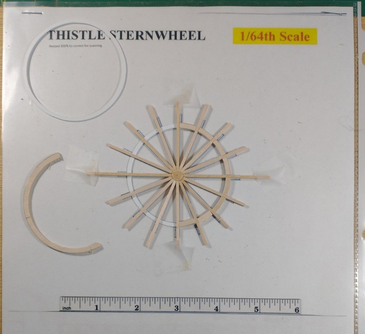
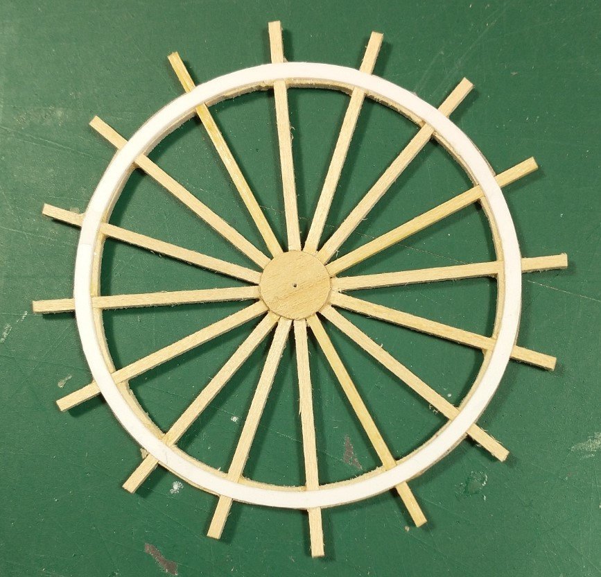
I would like to give a progress report on the sternwheel. Alan Bates Cyclopedium is an exceptional source that I used in this process. I drafted a copy of the sternwheel for my template. The arms and wood circle are 1/16 basswood, the flange 1/32 basswood and the "iron" circles are Evergreen plastic. I put the template in a clear plastic sleeve and then glued the parts together. It looked like this during the process. One of the three finished wheels ... I may still add in bolts, need to account for the shaft and clean it up. I am getting started on the 16 buckets (planks). I have yet to start the shaft although I had already completed the pillow blocks. I expect to paint it the same oxide red as the main deck. As an aside, I have been researching historic 1890s house paint colours for later use. The original paint chips are the only true period colours that I can find. [ The original grey in the Winneconne Steamboat House is the exception] Ironically, the shipbuilders - Ryan Bros., started their careers in Oshkosh as house builders. So logically, they were exposed to these colours as they built their "ships". I am wondering if I should use a Red Vermillion on the manual hand fire pump and pipes. Comments?
-
I want to thank Cathead, John, Keith and Roger on your kind words! As mentioned, I have had enuf' of small machinery for a while and am now working on the sternwheel. Roger, I was not aware that the tear shaped air chambers on the feed pumps were also bronze. I will definitely remember this in the future. Thanks for the info. I have also seen examples where the air chambers were cylinders with rounded ends but I thought the tear shaped looked neater.
-
I have completed the boiler and auxiliary feed pumps. These are also an amalgam of several different sources rather than a reproduction of a single source. I did not do duplex pumps like the Marine Iron Works photos but stayed with the simplex layout on several other photos. I have no idea which type Thistle had as both appear to have been common at that time. I also completed a General Electric Curtis Turbine Generating Set dynamo circa 1908. Thistle had electric added during 1901 maintenance. The other common alternative would have been a piston driven dynamo not unlike the one on the S. S. Moyie. Again, no idea which was actually used. I will add the wiring and conduit pipe later. There are several other hand pumps, levers &c. that need to yet be built. I will hold on these as I want to complete the sternwheel first. Crawford/Thistle had several sternwheels over its life. I will use the 1910 Paul L. photos as a guide as this is closer to the date of the model than say the J. H. Crawford photo from 1894 - 1898. Several other local steamboats referred to "heavy weather" sternwheels. It is possible that Thistle used one of these, as Thistle was known to run backwards, using the sternwheel to break up ice.

- 105 replies
-
- 12
-
-
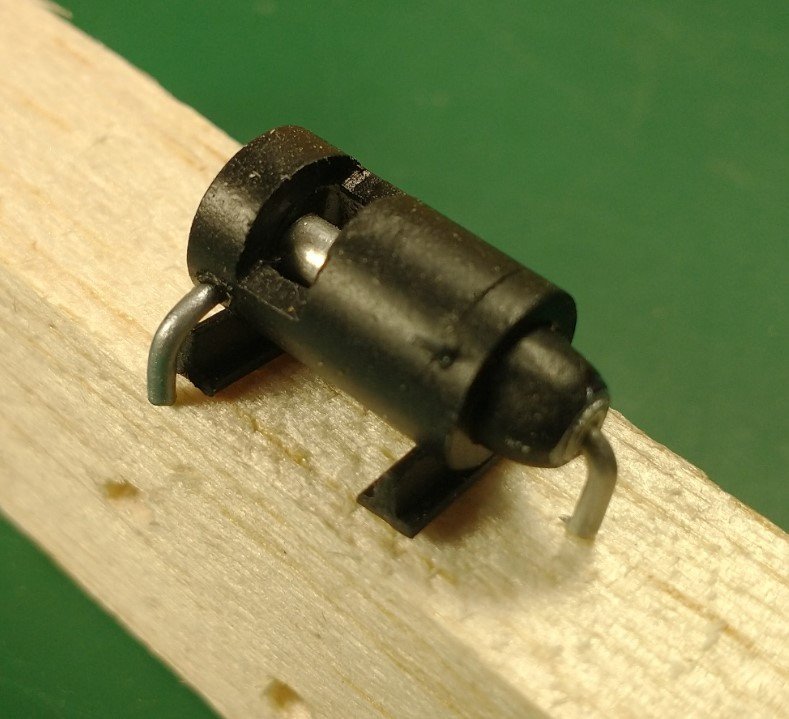
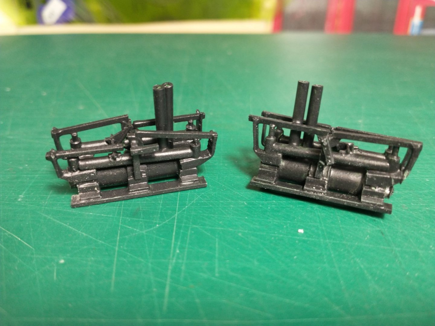
I have finally completed the two poppit engines. They are about an inch long each. The left engine is fully open so the arm on the sternwheel will be at 3 or 9 o'clock. The right engine is fully closed so it will be at 6 or 12 o'clock. I used photos from steamboats.com, The Machinery of Western River Steamboats by Colliery Engineer Company (circa 1900), a photo of a Mason engine and Marine Iron Works of Chicago as a guide. The result is an amalgam engine rather than a duplication of any. As Bates noted, the study of engines is a study onto itself. I used Evergreen styrene, Plastruct ABS and some small wire in the construction. Herein lies a tale of why it took so long. Part of the time was simply making something that looked correct in scale and detail. The bigger part was finally finding a glue or solvent to use. The final solvent is Pastruct Plastic Weld which seems to be methyl-ethyl-ketone (MEK). That MEK quickly melts the plastic to create the bond. A little goes a long way and is not forgiving in either time or placement. Before that, I made several models that literally would fall apart. I now have a debris filed littered with those unsuccessful attempts. I am now moving on to the boiler and auxiliary feed pumps. I trust that will not take as long as the engines did.
- 105 replies
-
- 18
-
-