HOLIDAY DONATION DRIVE - SUPPORT MSW - DO YOUR PART TO KEEP THIS GREAT FORUM GOING! (Only 68 donations so far out of 49,000 members - Can we at least get 100? C'mon guys!)
×

LJP
-
Posts
159 -
Joined
-
Last visited
Content Type
Profiles
Forums
Gallery
Events
Everything posted by LJP
-
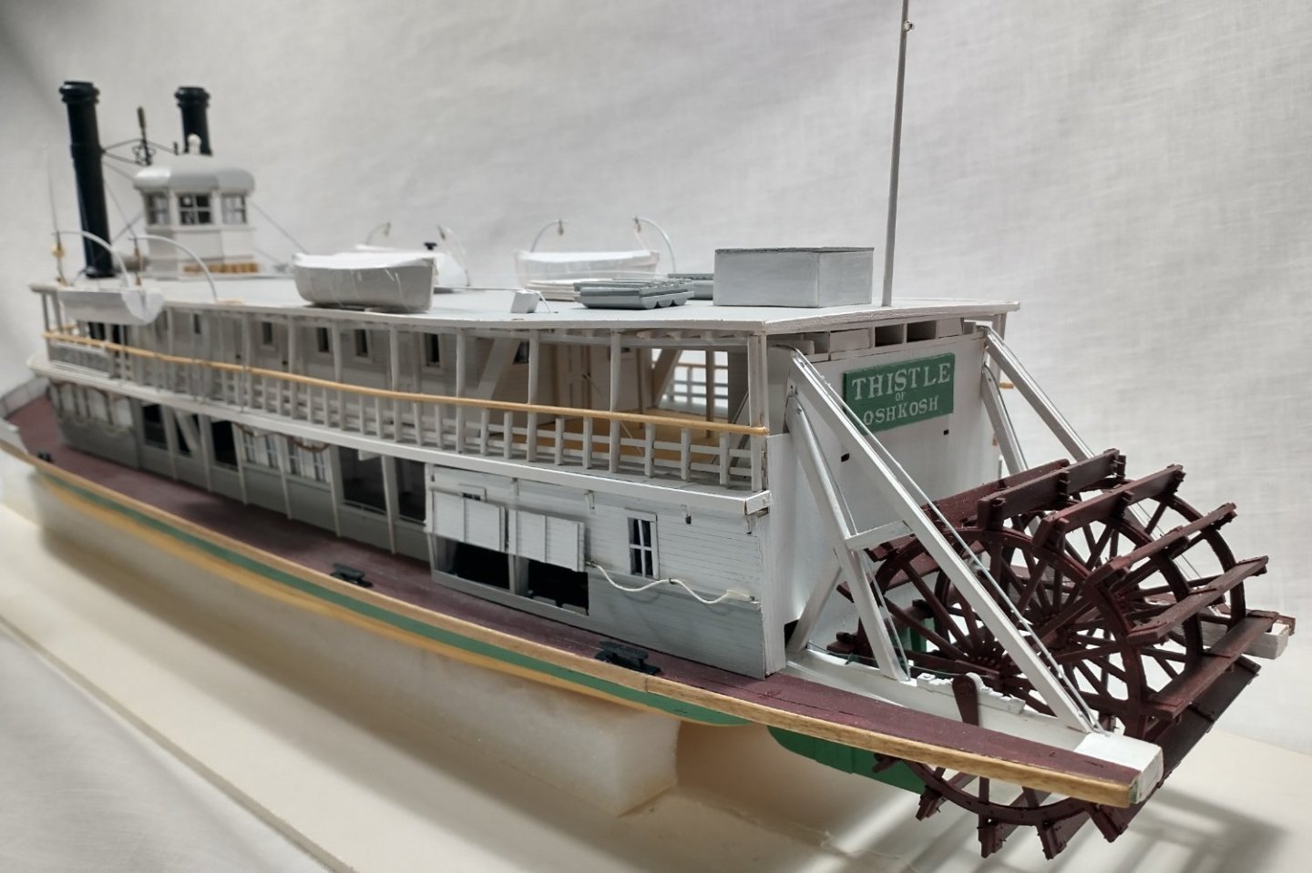
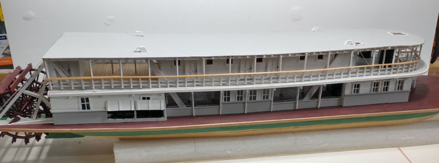
 I decided to paint the entire hull white for want of a better decision. This is the hull colour of many of the museum steamboats. Likewise, this was probably the most economical as no tinting was required. So white it is. I used Alan Bates’ method of combining the deck beams and the guard’s outriggers into a single beam. Much simpler and stronger. This is different from the Bertrand which had the outriggers separate from the deck beams. This is what my early gluing and clamping looked like. Lots of clamps… Another deviation was the outriggers at the stern where the wheel was located. Again, Bertrand had separate outriggers. However, JHC’s sister ship, the Paul L, had that area blocked in with timbers. This was evident with the Oshkosh Public Museum online photo of the Paul L when capsized. [I am not permitted to publish that photo here, but you can check their website.] So, I used solid blocking. This is what the final product looks like. My next project is to complete the main deck decking. There are a few issues there: 1. If the bow did not have a canvas or tarpaper cover, I would suspect the deck needed to be caulked. You would not want water draining into the hold where the coal bunkers are. Over the guards it makes no difference. 2. I may try something different for the hog chain braces. The braces really get in the way as you build the boiler deck and the staterooms. Maybe a guide in the hull where the braces can be removed during construction. 3. The same is true for the inner cylinder timbers with their support braces for the sternwheel. On Thistle, I completed them in situ – which was a horror story. Now I may make them a separate and removable component.
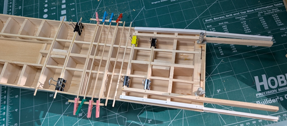
-
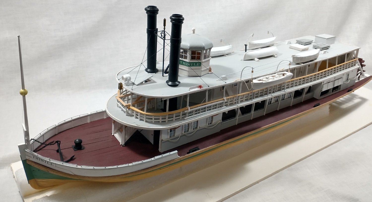
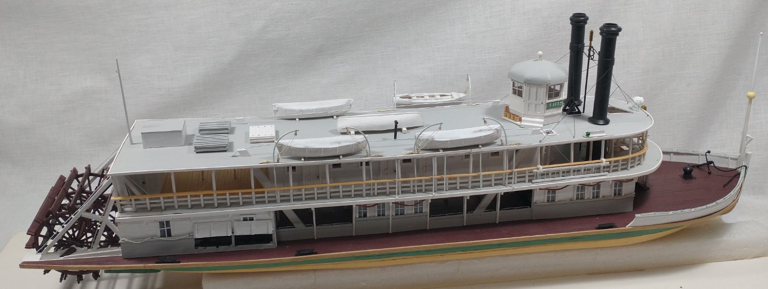
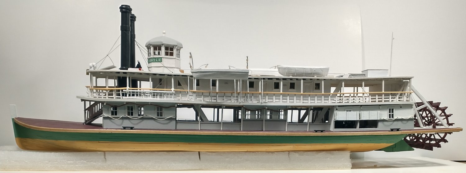
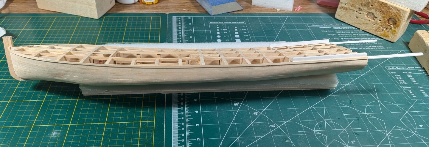
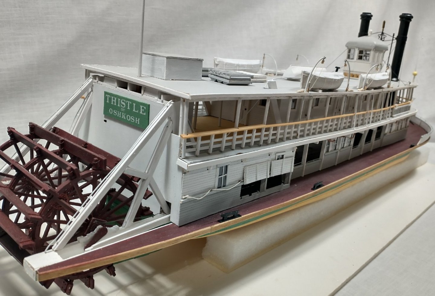
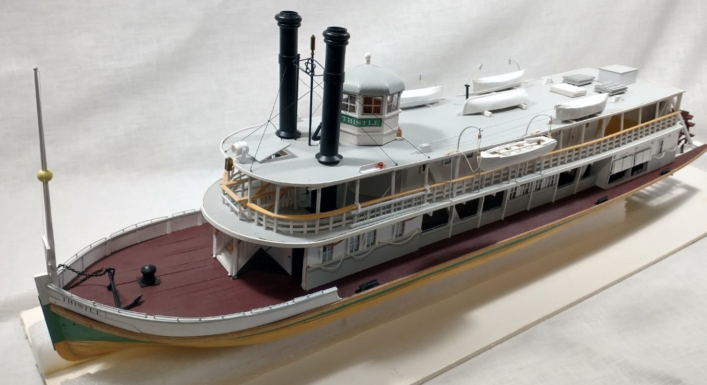
Well, its been a few months but my “other duties as assigned” are winding down. This has allowed me time to finally get the planking done. This has not been with out a few re-do’s on some of the individual planks but the product is now acceptable. I now need to paint the hull. If you recall, Thistle was historically accurate with a green upper and “two coats of boiled linseed oil” below the waterline, circa 1908. I do not know what JHC’s colours were. For below the waterline, I have seen discussions for white, black and oxide red. Above the waterline, later Thistle photos seem to be white, black and grey. Or so it seems, given these were black and white photos or colourized. The JHC photo at the beginning of this article seems to be grey. I would appreciate if anyone has insight into hull colour schemes. Otherwise I will pick period appropriate colours. Hopefully, my next entry will not take so much time as we head toward the holidays.
-
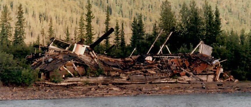
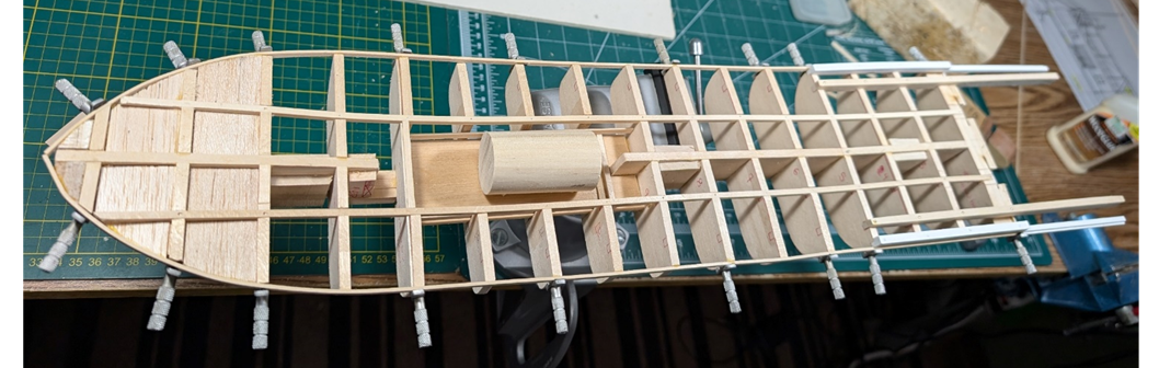
I have gotten things glued in and starting the planking It will take some time for the full planked hull due to other duties as assigned. I temporarily put the boiler in the pit. Again, it will be a while before I get to the boiler. The gauges for the boiler will have a bit different layout than what is normally seen on the boiler itself. I have a Marine Iron Works of Chicago USA brochure (one of several that I have) that shows a lithograph from a boiler that was reproduced from a photograph – so that layout actually existed. Stay tuned. JHC will have eleven wider bottom planks just like its younger sister boat, the 1907 Paul L had. The Oshkosh Public Museum has numerous online photos of the capsized Paul L in May 1910. The Paul L capsized when the coal cargo was unloaded from the starboard side but not the port. Predictable result. Over Paul L went, throwing crew into the cold Fox River. The Museum photos show not only the normal bow shots but there are two of the upturned stern views which prove invaluable. I obtained several of these Museum photos of excellent clarity, but I am not permitted to publish them here. I also own some postcard photos of the capsizing but not the stern shots. The actual JHC bottom planks were of locally sourced oak, while the Paul L were southern cyprus. The narrower JHC side planks were locally sourced Eastern white pine while the Paul L were Washington or Oregon Douglas fir. The change in material speaks to the rapid deforestation of Wisconsin in a less than fifteen-year period of time due to intensive and destructive logging. I used basswood throughout my model.
-
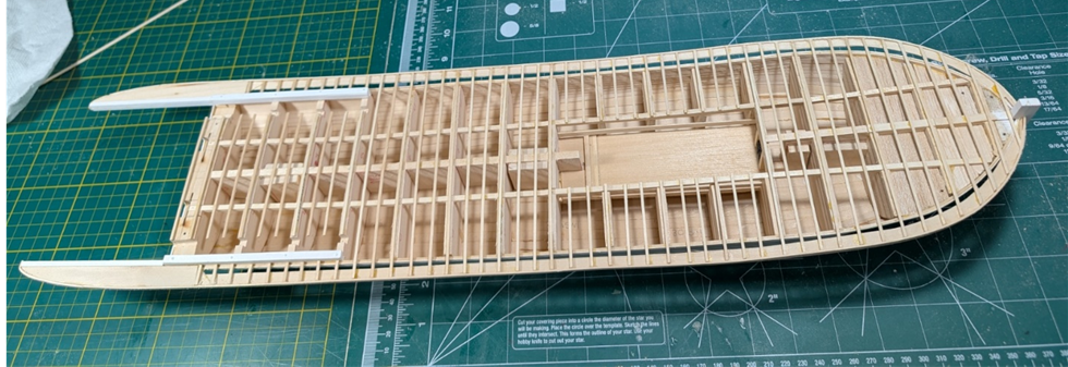
I cut out the frames and began to build the hull structure. Nothing below has been glued in place yet. The cylinder timbers are at the stern and additional longitudinal supports inserted. The supports will outline the boiler pit. JHC had a single Scotch Marine boiler below the main deck. It was noted that the engineer’s ladder slipped when he was going to inspect the boiler during construction. The engineer ended up with a broken arm and his left ear nearly torn off. Next steps will be cutting out the boiler pit and actually gluing things together. Things are going slower due to summer months and life's little adventures.
-
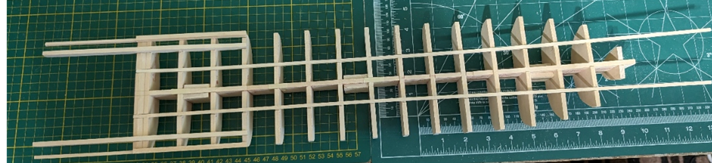
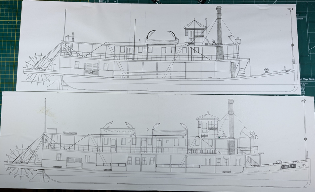
These are comparative 1:64 profiles of J. H. Crawford (upper) versus Thistle (lower). The obvious differences in the much simpler JHC is the 14-foot shorter length, but also an old type double stairs compared to a grand stairway. Most main deck windows are omitted as are the fancier bulwarks - including the bow bulwark. No electric in the early years, so a “railroad type” light was installed on the hurricane deck by 1895. Note the reduction or absence of lifesaving equipment: no rafts or life planks, only 2 yawls, and no boiler deck ladder. There are numerous subtle differences which will be evident later. Now I need to get started on cutting out the frames for my plank-on-bulkhead model. One of the things I did learn is that I really do not need as many frames as I used in Thistle. If I wanted to build a true framed model that would be different, but I do not want that much detail. I hope to build a stronger but more cohesive p-o-f model. What most are unaware of, is that the Thistle had an early launch that resulted in sprung planks, a destroyed stem post and a broken keel. Those type redo repairs I hope to avoid.
-
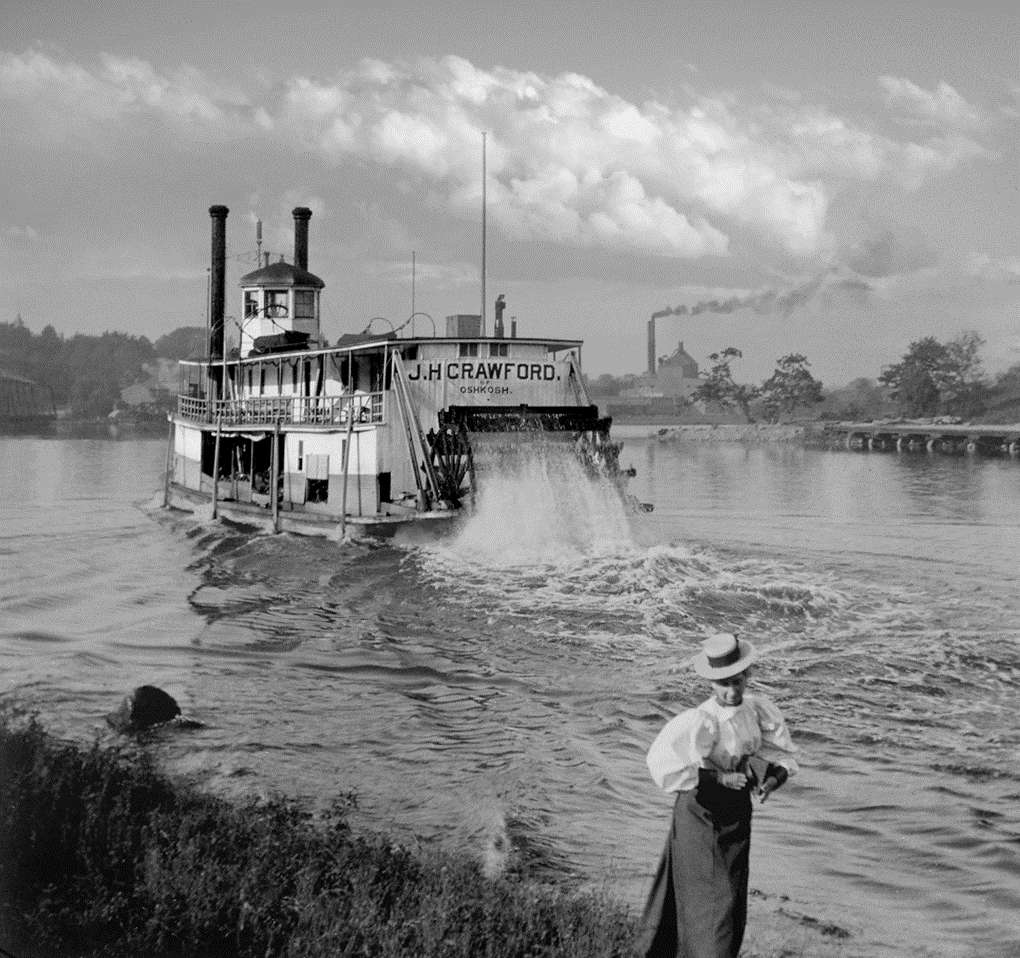
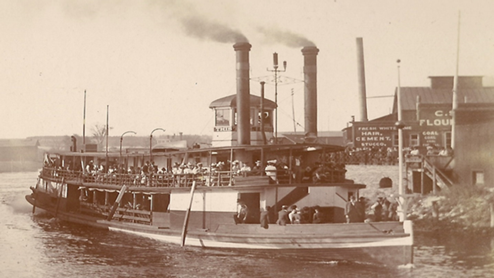
After three years since the start of my MSW build of the Thistle, I have decided to build the J. H. Crawford (JHC). As with my Thistle build, this will not be a fast process. I learned a lot from the Thistle build, and will need to be creative in making new mistakes on building JHC. I have also stolen ideas presented by others (Hi Cathead!) which will improve the quality of JHC. The J. H. Crawford was built in 1894 by Ryan Brothers of Oshkosh, Wisconsin for the Wolf River Transportation and Merchandising Company. George Ryan and his brother were Canadians who learned shipbuilding at Short Brothers in Maine. They later built Great Lake boats in Sheboygan and Manitowoc, Wisconsin before they finally began ship building in Oshkosh. Their Eastern and Great Lakes background had a profound effect upon the vessels they built. They modeled and lofted their boats which was unusual for these design-build boats. And George never referred to their creations as boats, they were always “ships”. Their long-lived boats were strongly constructed to weather the shallow but tempestuous Lake Winnebago but showed their earlier career influences. JHC was described as a “working boat” although it carried passengers. It had a 10 by 15 forward men’s “smoker” along with a same size women’s saloon aft. Initially it was designed for the circuitous Lower Wolf River at an overall nominal length of 130 feet by 25-foot beam. JHC’s entire life was spent on a section of the Fox-Wisconsin Waterway. This included the Lower Wolf up to New London, the Lower Fox up to Green Bay, the Upper Fox to Berlin, and Lakes Winnebago, Winneconne, Poygan and Butte des Morts. The new owners immediately had a falling out over the proposed Wolf River route for the JHC. Eight months later JHC was sold to the company of McKenzie & [ Captain John H.] Crawford. In May 1898 they in turn sold the JHC to Clark and LeFevre. Clark & LeFevre lengthened the boat by 14 feet and renamed it Thistle. At an overall 144 feet length, the now Thistle just fit into the 145 by 36-foot Fox River locks. Clark & LeFevre combined interests with the Oshkosh Steamboat Company in 1906. Thistle was finally dismantled at Green Bay in 1915 after a long 21-year life. There are only two known photos of JHC. One was a photo bomb at distance that was not useful. The other, presented below, is a wonderful quartering stern view that truly shows the difference between much simpler JHC and the latter Thistle. I first obtained this photo while building Thistle, or I probably would have built JHC first. Photo published courtesy of Dave Thompson Collection at Steamboats.com. Below is the bow view of Thistle but what the J. H. Crawford probably looked like, albeit 14 feet shorter and without the bow bulwarks. Note the double stairs to the saloon deck and main deck with bull rails. Thistle at Berlin, Wisconsin in 1901. Reprinted with permission from the Berlin (Wisconsin) Area Historical Society My next posting will show the profile drawings of JHC and Thistle, which really shows the differences between the two boats. I will again build in 1:64 scale.
-
Very nice! The details you added really make the model pop. I await your next one. LJP
-
Excellent model - just like the other two you shared with us. Absolutely love that you use your own lumber. I can hardly wait for your next one. You always choose great subjects. LJP
-
The Nautical Research Guild has an article on the "Myrtle Corey—1898 Memphis Riverboat: Research and Model Construction" BY WILLIAM R WISEMAN. Not certain how many years ago but certainly worth the read. Wiseman also had another NRG article and model of the Far West - also excellent. You can order the articles from NRG - but in my old age I have forgotten how I did it. You may now replay Nights in White Satin by the Moody Blues again. LJP
-
Cathead, Great Work! In re your hog chains, I put wire in a vise and then pull the other end with a pliers. It will stretch slightly and will straighten the wire out. LJP
-
Really looking forward to your first scratch build. It is great that you were able to get a set of detailed plans. I was able to see the outside of the boat when I was in Whitehorse in the mid-1990s but the boat was already closed for the day and we left too early the next morning. LJP
-
Hi Cathead, Great job! Another alternative on the stacks is K&S aluminum "pipes". They are stable, can be drilled, and have the open structure that you are looking for. You can still use the plastic bands. Keep up the good work, LJP
-
Hi Eric, As steamschooner mentioned, the reference that I found was that the decks were "canvas, painted and sanded". This is what was done on the S. S. Moyie when four layers were removed during renovation. I like your idea of scribing the underside of the boiler deck, That provides a good representation while really simplifying the process. Keep up the great work., LJP
-
Hi Cathead, I missed your build until now but definitely will follow it. GREAT WORK. Love the topic - a model that others have not done before. Working from just photos is not easy. This is especially true where the layout changes over the years and you need to decide what period to follow. Specifically I love how you built the guards. These are a real pain to build. Awaiting your next update... LJP
-
Your collective support is amazing. Thanks again. Kurt, I have attended the Wisconsin Maritime Museum model contest several times. The level of construction exhibited is well beyond my Thistle. The regrettable part is many years ago I kit bashed a Thermopylae clipper which could have been entered into the contest. That said, I may display Thistle at Manitowoc through the Wisconsin Scale Boating Association (WSBA) of which I am a member. I agree that it is unusual and will draw interest. There are several other WSBA events where I will display it. My next project is the neglected “Honey, Do…” list items I had successfully avoided. But my next boat project is the logical choice: the predecessor of Thistle, the J.H. Crawford. During the Thistle build, I was able to obtain a wonderful quartering stern view of J. H. Crawford from the Dave Thompson Collection at Steamboats.com. I will need to create J. H. Crawford plans as Crawford really looked different (and was 14 feet shorter) than Thistle. I look forward to that build as I now have experience to rely upon. But that build will not be fast either. Cathead, your models are incredible. Like you I will enjoy my model in my home. I have already given thought to where it will go when I no longer need it. There are several city museums or county historical societies which Thistle regularly visited during its life. I would hope that it will reside in one of those because of its connection. Roger, thank you for your insights. I have visited your whaleback Meteor and museum. Definitely worth the visit but I never saw the plastic Titanic. If you wish to build an interesting sternwheeler with both a Fox River Valley and Duluth connection, the Henrietta (1879) was a government boat, later sold to local Fox River Valley interests as a packet, and sold a second time in 1895 and ran excursions on the St. Louis River from Duluth to Fond du Lac (yours, not mine). Its barged-out hull is in the Thunder Bay graveyard. Keith & MCB, thanks for you confirmation – it really means much. LJP
-
I give you Thistle I would like to start by thanking all of you have who have encouraged me and followed my build over these past two years. To say that I have learned a lot, from drafting the plans to the actual build, would be an understatement. This was my first true scratch-built model and I am glad that I did it. I have discovered ways to do things wrong that truly amaze even me. I have also discovered that the eyes are not as sharp as they once were and the fingers less nimble. While Thistle will never be in a contest, the soon to be cased Thistle will proudly reside next to my fireplace. Thank you all again. LJP

- 105 replies
-
- 15
-

-

-
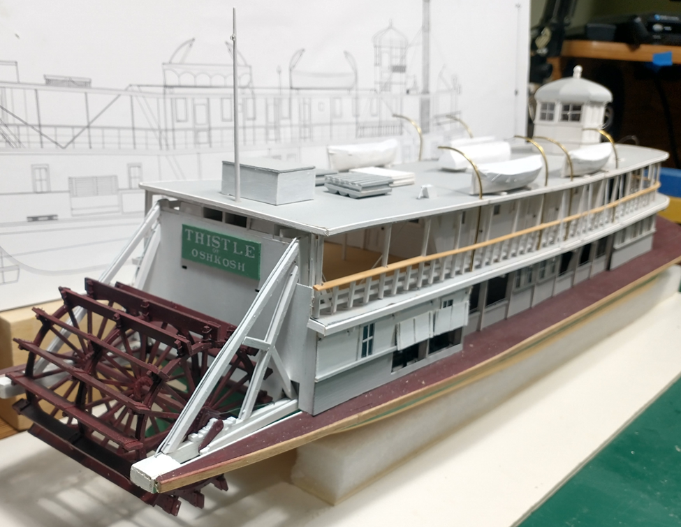
I am finally getting close to the end of my Thistle build after two years. The hurricane deck was finished with the addition of fire buckets and the bell. The boiler deck had "Official Notices" in 2 height font attached. A ladder to the pilothouse was added along with the two ladders attached to the railings. The latter were the federal fire requirements after the General Slocum disaster. The main deck had the canvas coverings attached above the bulwarks, although they are hardly noticeable. Firehoses were added to the underside of the boiler deck. The firehoses were located under the hurricane deck in the early years. The change may have also been a requirement due to Slocum. Safety ropes were affixed to the boiler and engine superstructures. Lastly, kevels (a/k/a cleats) were attached to the main deck. So what is left is on the main deck at the bow. A capstan, anchor, bulwarks and jackstaff are still needed to finish the project. But again, during summer, modeling takes time. I hope to finish in August - the month Thistle (as the J.H. Crawford) was launched in 1894, and as Thistle was sent to the breakers in 1915. That I started and finished the build and will finish it in August is pure coincidence.

- 105 replies
-
- 15
-
-
-
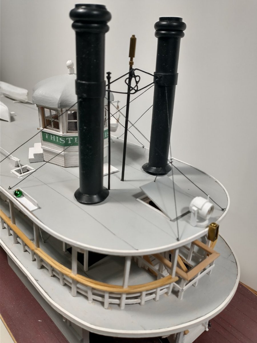
Cathead & John, thanx for the kind words. I really get little modeling done in summer but I have pretty much finished the hurricane deck except for the bell and lots of paint touch-up. After I complete that it on to final touches on the boiler deck: ladders, hoses, placards &c. Two different perspectives, the latter photo is wonky due to the photo's perspective. The stacks were a bit of a challenge. The stacks themselves are 1/2" K&S aluminum tube with the tops of half round Evergreen or Plastruct. The spreader is shaped copper wire with the whistle and vent brass tubing. There will still need to lots of things done on the main deck but Thistle looks like a sternwheeler and an end is getting closer after nearly two years.

- 105 replies
-
- 12
-
-
-
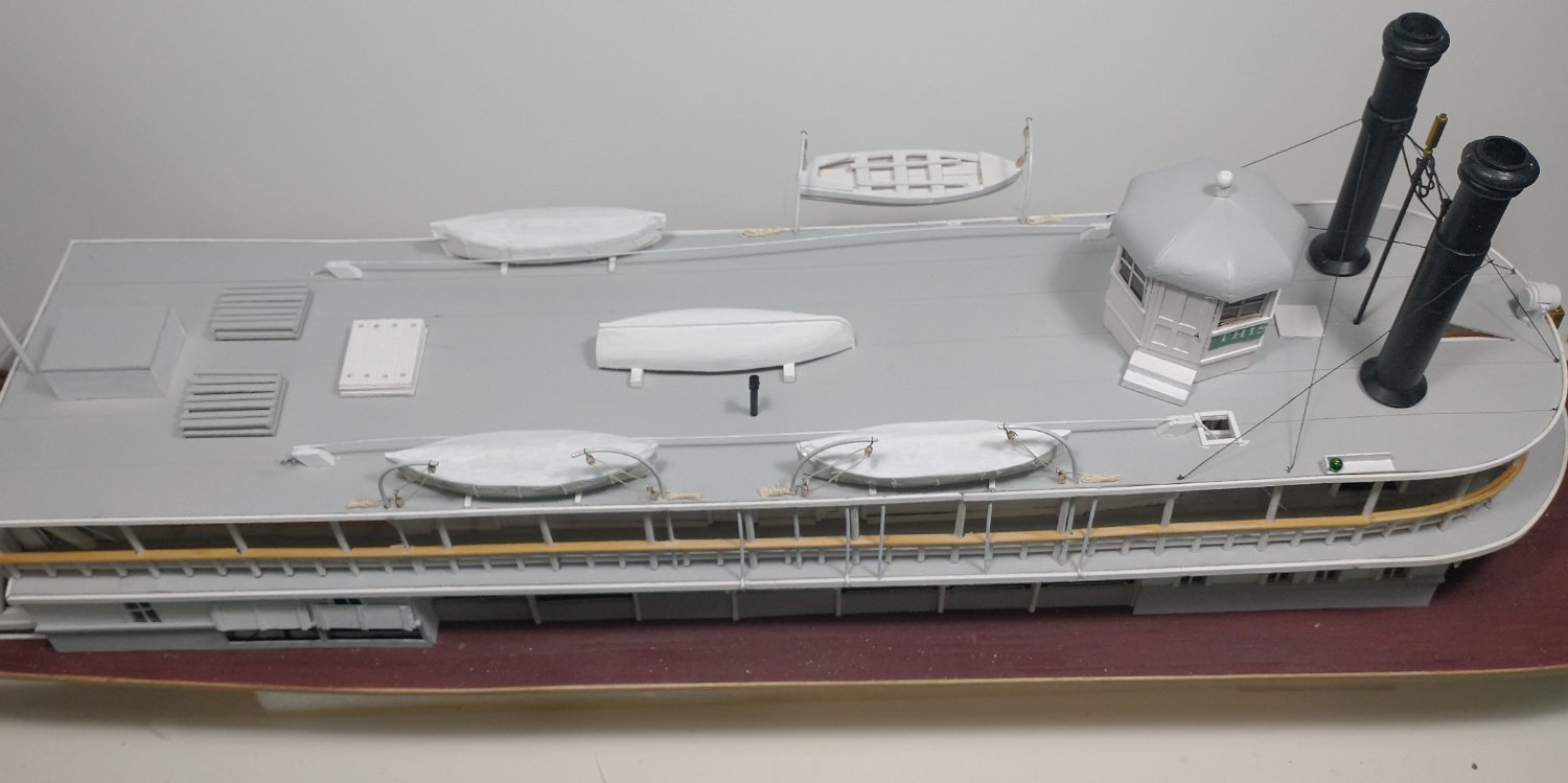
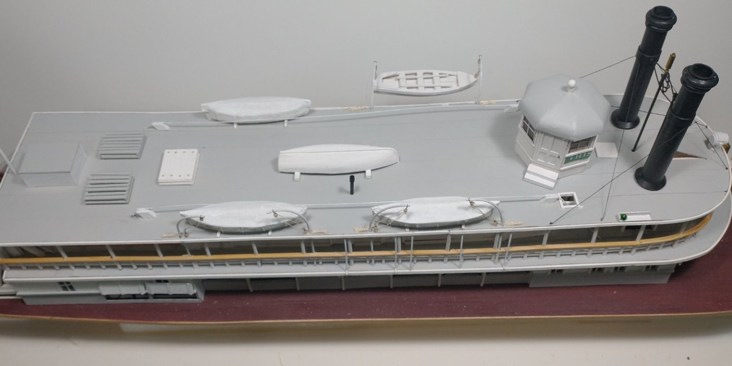
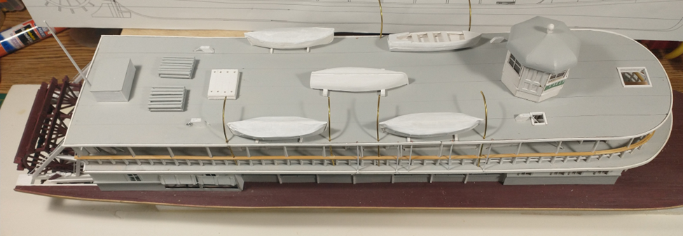
boboandlucy, Thanks for your kind comments on the pilothouse. It was a bit of a challenge to make. An updated hurricane deck. I have added the verge pole, water tank, rafts, safety planks, and five boats ,along with the unfinished davits. All are just placed and not affixed to the deck. I have lots of detail work that still needs to be done here. I did add the three drains from the hurricane to boiler deck, along with the two additional hurricane deck supports for the forward life boat. I am thinking about adding the stacks and then coming back to do the detail work. It is starting to look like a sternwheeler but still has a long way to go. Once the hurricane deck is complete, I still need to do all of the bulwarks, capstan and jackstaff at the bow. And tons of little odds and ends that I have yet to start.
- 105 replies
-
- 13
-
-
-
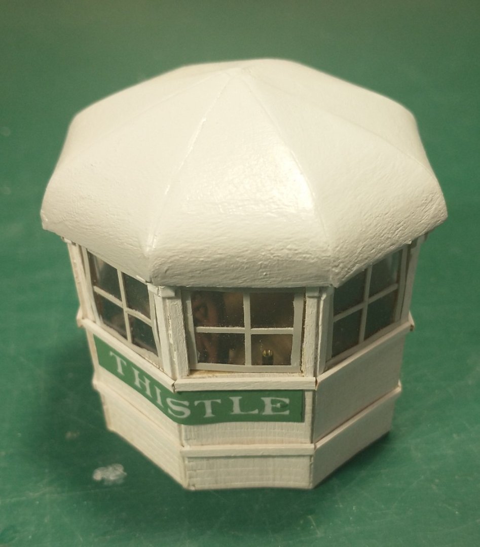
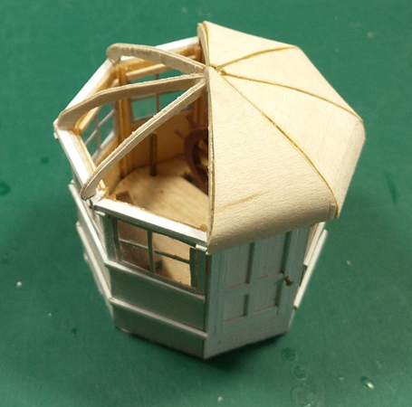
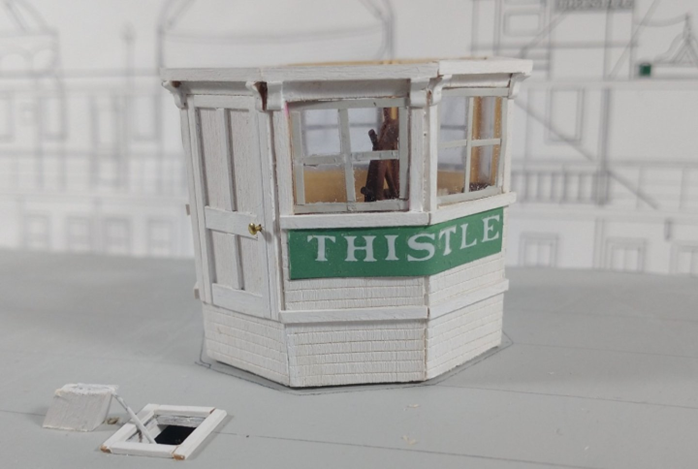
The pilothouse roof is on. For the roof supports I used 1/32 birch plywood. This is much stronger than the 1/32 basswood that I had used for the superstructure panels. The roof panels are 3/84 maple veneer. I soaked then in water so I could bend them at the base of the roof. The panels were standard with a little trimming to fit. The finished product after sanding, sealing and painting. I still need to add the filial on top and make the stirs to the pilothouse For the next project, I will start at the stern of the deck and build all of the attachments; verge pole, water tank, rafts and safety planks, and five boats. Some of this will go quickly but the boats may take some time.
- 105 replies
-
- 12
-
-
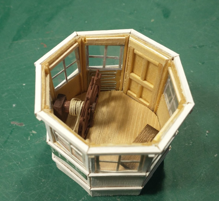
I assembled the pilothouse. Again, took longer and several attempts. Still not really satisfied with it but I will now finally start the roof. I still need stairs to the door. The interior photo shows the wheel, part of the lazy bench and the radiator. Speaking tube is hidden in this photo. I am not certain if there was a compass. There were references to Thistle missing its landing in the dark or in fog so I wonder if there was one or if it was not used.
- 105 replies
-
- 14
-
-
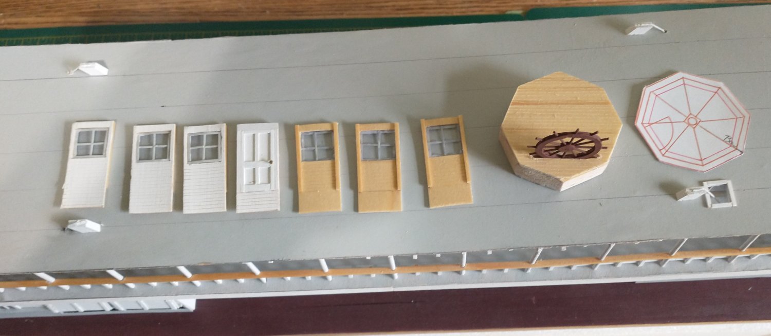
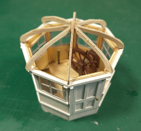
I have built the panels and the base along with the wheel. The wheel was "about six feet across" and Bates said 2 spokes per foot diameter so I needed 12 spokes. This looks about right for the number of spokes per photos. Photos also had the wheel about mid-height of the pilothouse windows so I needed to cut into the base to shorten the height of the wheel. Several other photos had the pilot standing outside the pilothouse on the port side while steering. The wheel is close enough to the windows to allow this. I intend to affix the panels to the base, add in all of the pilothouse parts and pieces (wheel, lazy bench, radiator, speaking tube &c.) and then start on the roof. I expect the roof will take a few attempts before I get it right. Some photos did show a visor but I have found none with breast board. I will probably include neither as the pilothouse windows will be closed.
-
G'Day! I am back from over five weeks with Tassies, Aussies and Kiwis. [a/k/a my family duties] The countries are wonderful but it is really the people that are the most wonderful. But care must be taken at the pubs with the locals and the consumption of "stubbies". It may be another week or so before I can dig out and get back to modeling.
-
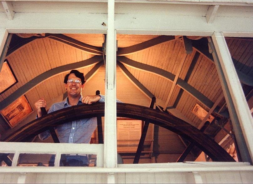
I have started on the pilothouse. I will break this project into two parts, the roof, and everything else. This is how far I have gotten on the "everything else". No photos yet because... I started with an eight-sided balsa and basswood floor base that will provide support to the panels. The floor and base need a cutout for the described "about six feet across" wheel which is about 1/3 below floor level. The actual Thistle wheel may still be at the Oshkosh Yacht Club, but I have not followed up on this lead yet. I had built the eight panels, seven with windows and a single door panel. It will be interesting to properly attach those into a hex layout even with the aforementioned base. Unfortunately, I am not satisfied with the initial results, especially the windows. Back to the drawing board and a re-do. The unstarted interior will be fairly simple: wheel, lazy bench, compass, speaking tubes, pulls for the bell & whistle, and a radiator. There was not a stack for a pilothouse stove so I will go with a radiator. Period radiators appear to be pipes run back and forth as on Yukon steamboats rather than the traditional 1920s free-standing radiator noted on Moyie. The interior will be boiled linseed oil instead of the sea green paint espoused by the Moyie preservation. The roof will be a challenge and I will save that for last. There are a few photos that will assist me in the roof process. From Online Steamboat Museum Dave Thomson Collection [Steamboats.com/museum] an excellent photo of the underside of the Golden Eagle pilothouse. Although this is a square pilothouse, it gives a great idea what the underside of the roof a real pilothouse would have looked like. No idea who the "pilot" at the wheel is. Note the legal requirements posted to the ceiling in order to passive-aggressively fulfill federal requirements of required certificates etc. being conspicuously posted. I have extended "family duties" that will prevent me from working on the model for at least the next several weeks. But I will get back to things as soon as I can.
-
The hurricane deck is now attached. I used Midwest 1/64 birch plywood, scored and painted white on the underside, spray adhesive and tracing paper painted grey on the top. You cannot tell from the photo but the top is lined to simulate the canvas seams. Now I need to build and then add numerous things to the deck: stacks & pipes, a bell, pilothouse, boats, rafts, water tank, verge and numerous other small items. The I can add the hog chains and complete the facing.
- 105 replies
-
- 16
-