Stephen Allen
NRG Member-
Posts
22 -
Joined
-
Last visited
About Stephen Allen

Recent Profile Visitors
-
 Stephen Allen reacted to a post in a topic:
Potential 1/48 Higgins PT kit
-
 Stephen Allen reacted to a post in a topic:
Libertad 1925 by Valeriy V - Scale 1:100 - Spanish Type F Light Cruiser
-
 Stephen Allen reacted to a post in a topic:
USS Cape (MSI-2) by Dr PR - 1:48 - Inshore Minesweeper
-
 Stephen Allen reacted to a post in a topic:
St Roch by Lecrenb - 1:48 scale - RCMP Schooner rigged as schooner c. 1930/35
-
Stephen Allen started following Potential 1/48 Higgins PT kit
-
 Stephen Allen reacted to a post in a topic:
Potential 1/48 Higgins PT kit
-
 Stephen Allen reacted to a post in a topic:
USS Cape (MSI-2) by Dr PR - 1:48 - Inshore Minesweeper
-
 Stephen Allen reacted to a post in a topic:
USS Cape (MSI-2) by Dr PR - 1:48 - Inshore Minesweeper
-
wmherbert started following Stephen Allen
-
Thanks Jim Thought that might have been the case. It was a good tip about centre of gravity placement for the eyebolts/hooks though; not something I had put my mind to but obvious once pointed out and explains why lifeboat plans show them mounted above the C of G . At the moment my bible for merchant ship details is John Bowen’s A Ship Modelmaker’s Manual along with the usual suspects from P N Thomas and C V Waine, and Lloyd’s rules and regs for the period. cheers Steve
-
Thanks for the answers and especially the photos. I think I have the sense now of how you can have a cover, and still have the falls attached to the hooks or eyebolts, and have the cover rapidly removed when so needed. Given that I am using covers, then a representation of the laced openings is pretty much all I will need, as any disengaging gear - like the RN’s Robinson version, would be under the covers, so to speak. Incidentally there are plans of lifeboats with raised hooks or eyebolts, which would place them above the boats centre of gravity, naturally avoiding the tumbling issue described. many thanks Steve
-
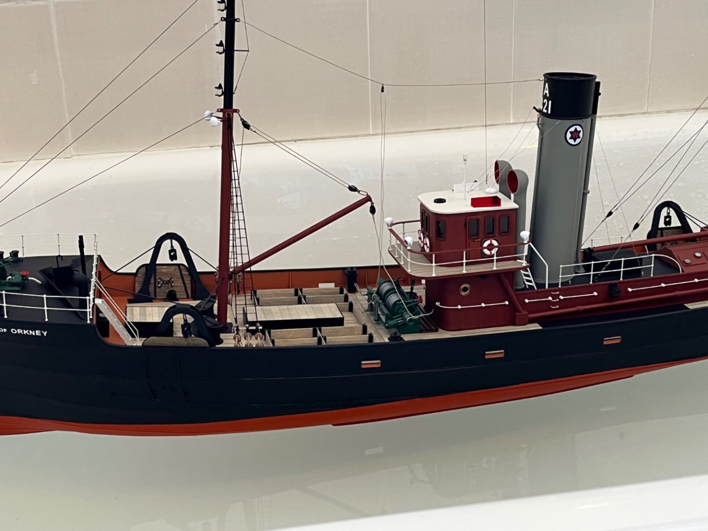
I am building a 1920s/30s era British Coastal Steamer, and wanted to depict the lifeboats with tarpaulin covers rigged. With the covers over the boats, I am a bit perplexed as to where or whether the lower block on the falls attach to the boat. They would normally attach to eyes or hooks located within the boat, easy enough to depict with the covers off. But I haven’t been able to find a photo showing what happens to the falls when the covers are rigged. Are they slacked off and allowed to drape under the covers at each end, or are they tied off to the davit itself? I have seen one or two models which show the falls somehow being attached to the covers, or perhaps going through them - neither seems a sensible proposition at sea as it would put the cover in the way if the boat had to be launched. If anyone could assist, or point me towards a photo/illustration, it would be most helpful. None of my internet browsing, books, plans etc cover this point. cheers Steve
-
Wire rigging for 1885 Puritan by Mamoli
Stephen Allen replied to bridgman's topic in Masting, rigging and sails
I have found beading wire problematic because of its reluctance to bend without kinking, and because it needs a fair bit of tension to straighten out, putting a lot of strain on the mounting points and masts. I build in 1/48 and 1/72 mostly. If you don’t want to use beading wire, then YLI make a range of silk threads in metallic colours ranging from a bright silver to a dull gunmetal. These can be twisted up on a rope walk like any other thread, although I have found that the ends usually need a little glue to prevent unravelling. The thread is naturally not fuzzy. The metallic look is easily dulled by a coat of matt varnish if you wish, but it isn’t objectionable - its not sparkly or anything. Gutermann also make a range of upholstery threads which come in a dark grayish colour that works well too. 1/48 with Gutermann upholstery thread on the left. Various YLI-based three strand standing rigging lines in 1/72 on the right ( its a work in progress shot so please excuse the stray ends). I use this in a single strand to replicate wire rope safety lines as well. Both can be tightly wound through blocks, pulleys etc, knotted, or secured with small crimps or bottlescrews, and don’t need a lot of tension. Steve. -
Richard Sorry for coming to the rivet discussion late, and I may have missed an earlier post, but have you looked at the Meng range of surface details? They have round head rivets in various sizes in one of their sets, SPS-009. They are standard model styrene, injection moulded onto flat strips. You slice them off with a razor blade or similar, then glue them to the surface, liquid cement to styrene, superglue to other surfaces. Range from 0.8mm up to 1.4mm or so. Lots of other profiles as well, nuts, bolts etc of various sizes and shapes. Consistent size and shape unlike many of the resin equivalents. A bit expensive but good. Most online hobby stores stocking accessories for AFV modellers have them. I have used the Archer decals also. They are a bit trickier to use, lower profile and a little less consistent in shape, have to be carefully applied then avoid using high tack masking tape over them as they can rip off. Advantage is they come in standard spacings and multiple rows. Steve
- 454 replies
-
- Union Steamship Company
- Stepcraft 840
-
(and 3 more)
Tagged with:
-
DAS WERK - 1/72nd - Naval Dry Dock Kit
Stephen Allen replied to yvesvidal's topic in Plastic model kits
No need to answer, finally found it - 1008mm -
DAS WERK - 1/72nd - Naval Dry Dock Kit
Stephen Allen replied to yvesvidal's topic in Plastic model kits
Hi Bear Looks interesting! How long is the Dry Dock? Have looked online but can’t find a Length measurement thanks Steve -
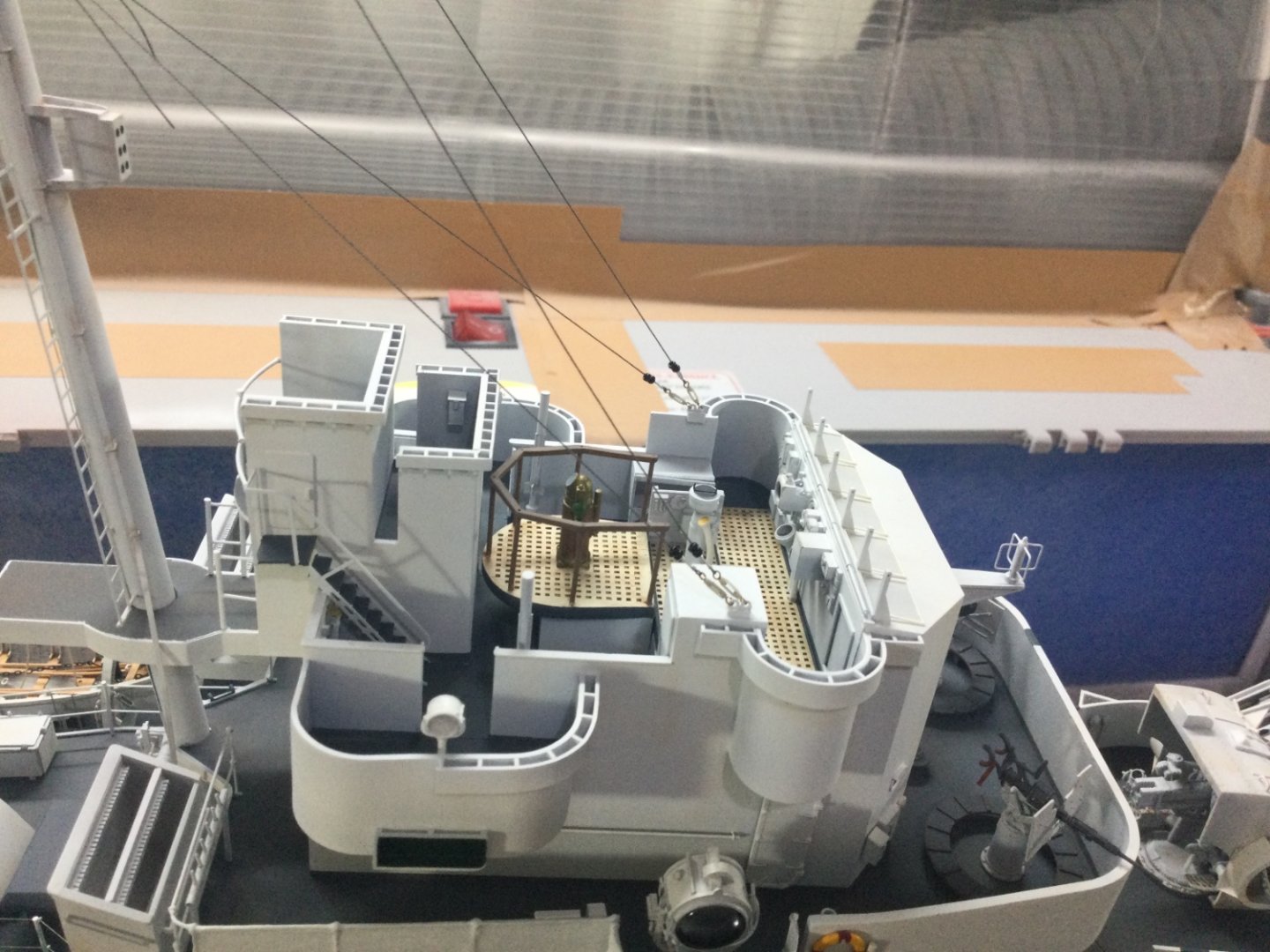
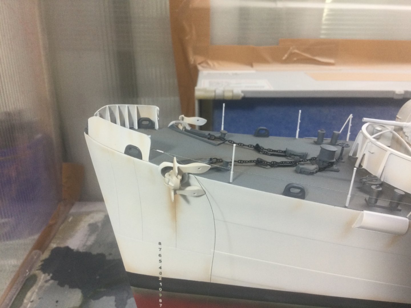
This is an amazing build Richard, and what a presence she will have on the water. I have just, nearly(!) almost finished building an RN WW2 Frigate to 1/72 scale, much tinier. The order and time of painting is something I though long and hard about, as painting major bits too early can lead to a lot of rework and cleaning as you continue the other dirty bits of the build. Your build has interior detail painting so some of that will inevitably need to be painted early, then protected for the duration of the build, but the method I chose was to leave finish painting of the hull and superstructure to the absolute last possible stage, so that the model could be thoroughly cleaned, prepared, then not dirtied/ dusted up again. To do this you need to be able to plan subsequent fitting of details in a way that allows you to avoid marring finished surfaces again. In your chosen gigantic scale, many of your fittings could be made to remain detachable using rare earth magnets, which eases both painting/masking and any subsequent repair, and makes it easier to set up for sailing without knocking things off. Some could simply be mounted on spigots and gravity will keep them in place. In my scale I also built different stands to allow me to do things like invert the hull, support the superstructure etc, in a way that allowed me to paint structures without handling them. These also need to be planned and built in advance then tested to ensure they won’t damage anything in use. Quite how you do that with a ship the size of a small car I don’t know! Best wishes with your build! Steve
- 454 replies
-
- Union Steamship Company
- Stepcraft 840
-
(and 3 more)
Tagged with:
About us
Modelshipworld - Advancing Ship Modeling through Research
SSL Secured
Your security is important for us so this Website is SSL-Secured
NRG Mailing Address
Nautical Research Guild
237 South Lincoln Street
Westmont IL, 60559-1917
Model Ship World ® and the MSW logo are Registered Trademarks, and belong to the Nautical Research Guild (United States Patent and Trademark Office: No. 6,929,264 & No. 6,929,274, registered Dec. 20, 2022)
Helpful Links
About the NRG
If you enjoy building ship models that are historically accurate as well as beautiful, then The Nautical Research Guild (NRG) is just right for you.
The Guild is a non-profit educational organization whose mission is to “Advance Ship Modeling Through Research”. We provide support to our members in their efforts to raise the quality of their model ships.
The Nautical Research Guild has published our world-renowned quarterly magazine, The Nautical Research Journal, since 1955. The pages of the Journal are full of articles by accomplished ship modelers who show you how they create those exquisite details on their models, and by maritime historians who show you the correct details to build. The Journal is available in both print and digital editions. Go to the NRG web site (www.thenrg.org) to download a complimentary digital copy of the Journal. The NRG also publishes plan sets, books and compilations of back issues of the Journal and the former Ships in Scale and Model Ship Builder magazines.


