KurtH
-
Posts
449 -
Joined
-
Last visited
Content Type
Profiles
Forums
Gallery
Events
Everything posted by KurtH
-
Sorry to be so late in answering your question. I used the clunky Britannia Metal cast trailboard. I did not have to remove wood from the stem knee to get a good fit at the end, but I regretted not having tapered the stem knee to a point before gluing them on. I did encounter a host of other similar problems throughout the build. It seemed that I was constantly fettlin things in order to make everything fit. E, g, the main fife rail assembly was a nightmare. Being inexperienced at building from wooden kits, I just thought that it was part of the process.
-
My BJ kit did supply a Britannia metal cast of the Lion face. However, it is square rather than rectangular as is the current sculpture
-
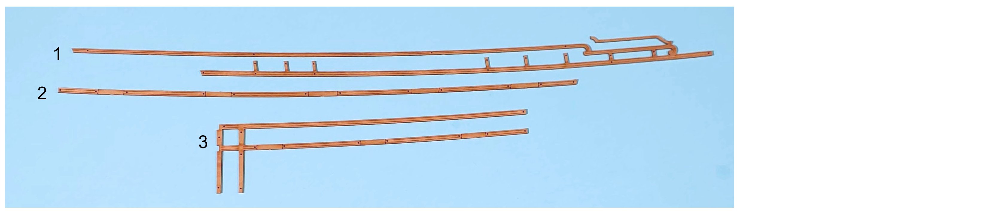
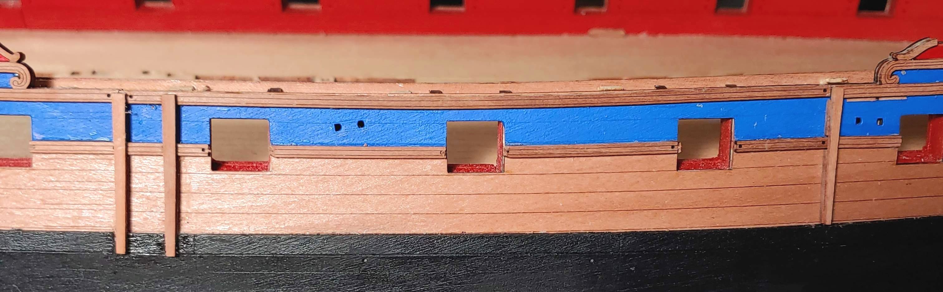
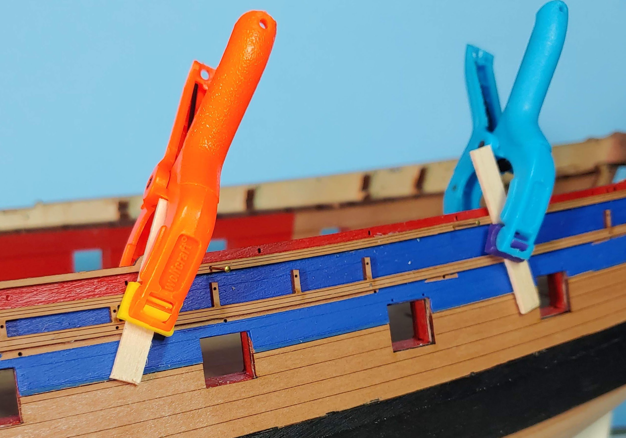
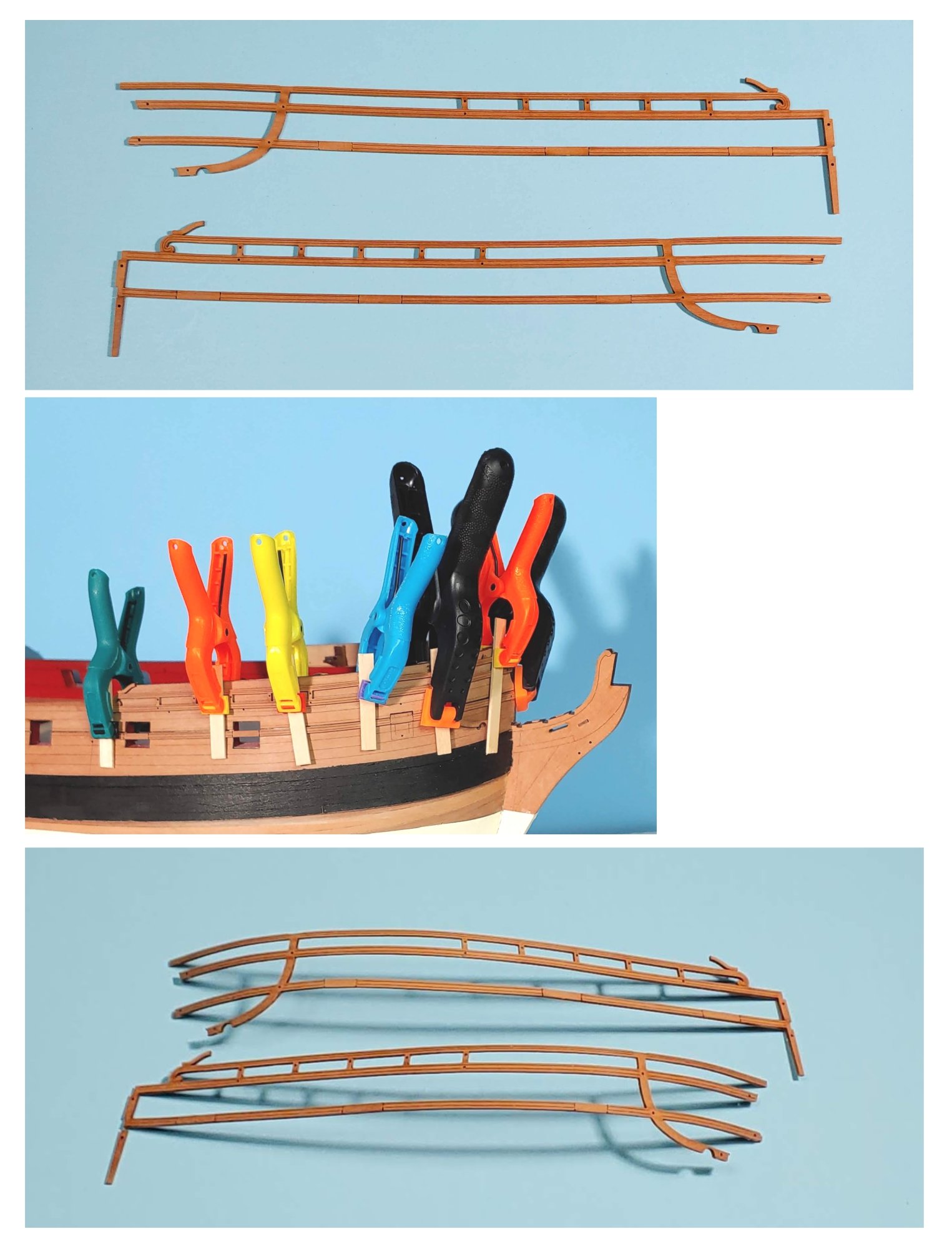
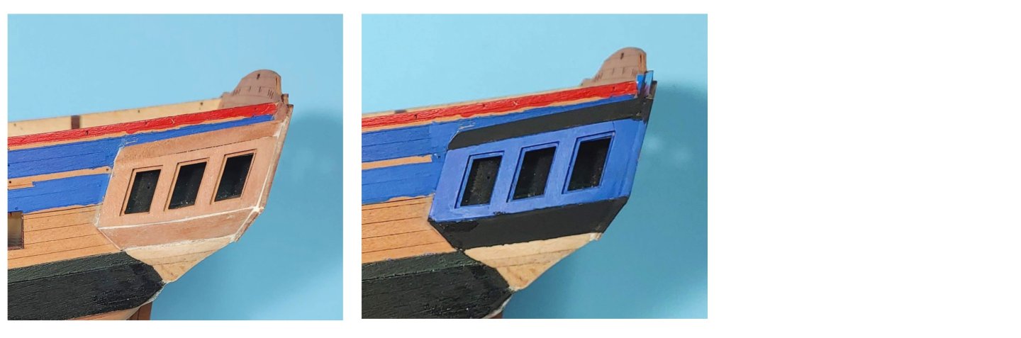
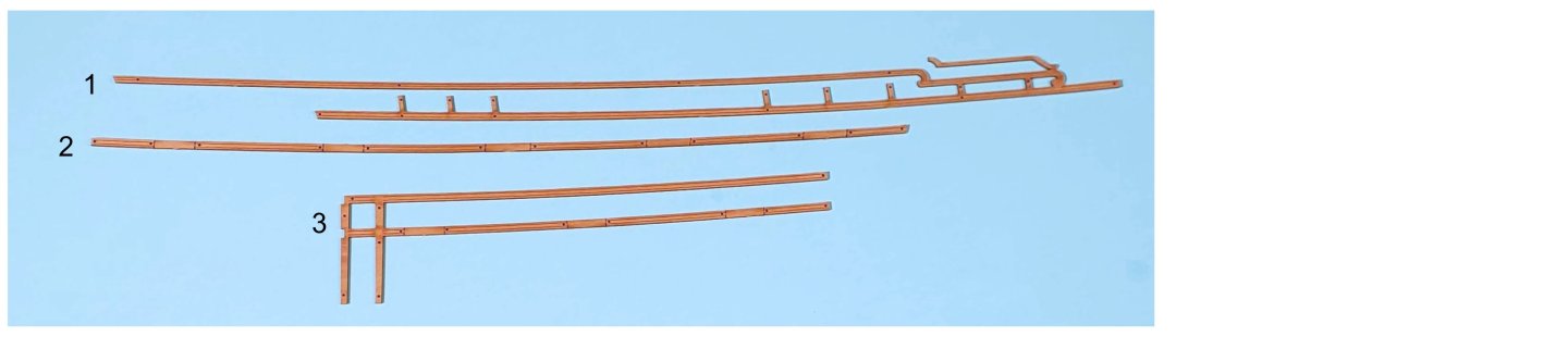
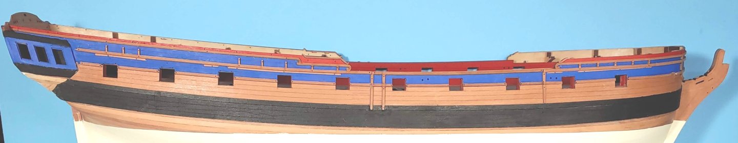
Quarter gallery filled then painted: Rail patterns: 1. Sheer rail pattern 2. Waist rail pattern 3. Sheer and waist rail pattern The pin holes provided in the rails and in the hull were critical in being able to place the rails in place quickly and accurately before the glue set. Rail patterns installed: Side fender patterns (left), and chess tree patterns (right) Fender and chess tree patterns installed: Current state of play: It is time for me to step away from this build in order to do my yearly video job. I expect to resume work late in July.


-
Check to see of the stem and stern post align. I neglected to do that and paid the price later
-
Thanks Ron! Your work on the quarter galleries is really amazing!!
-
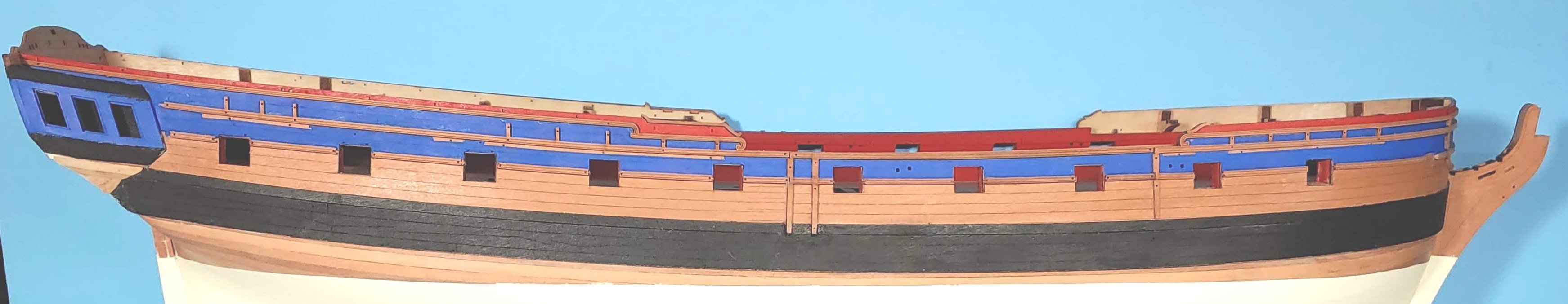
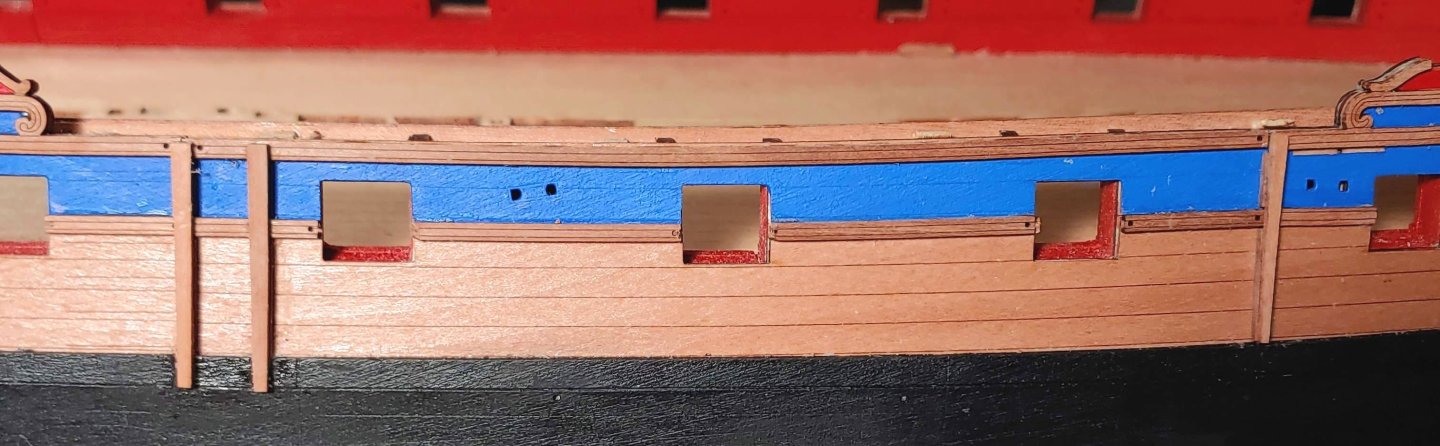
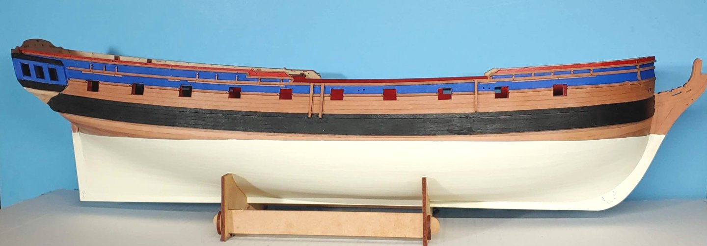
Modification of the cradle to prevent marking up the ship's bottom. Ship unmasked and set on the cradle: Preparation of the forward rails: I have painted the hull in preparation for the rail installation. The colors are Tamiya Flat Red (Same as the interior), and Vallejo Royal Blue. Since I plan to use Vallejo Yellow Ochre for the decorations rather than Gold, I thought a deeper shade of blue would create a better contrast. Vallejo Matt Acrylic Varnish was used for the natural wood areas, and as a base for the paint. I am not sure that I can install the rails before going out of town for 2 weeks, so I thought I should post what I have now. I just realized that more filling needs to be done on the quarter galleries, so I am leaving them unpainted for now.


-
In a book of photos published in 1991 which I bought when I visited Constitution, foretack boomkins are in place. They look identical to those on the Hull model. I am guessing that since the courses were not set when they last sailed her, and likely will not be set if they sail her again, the boomkins will no longer be needed, hence their present absence.
-
Here is one: Hope this helps.
-
I have been unable to replicate the search that turned up those photos, but here is one more that I downloaded at that time.
-
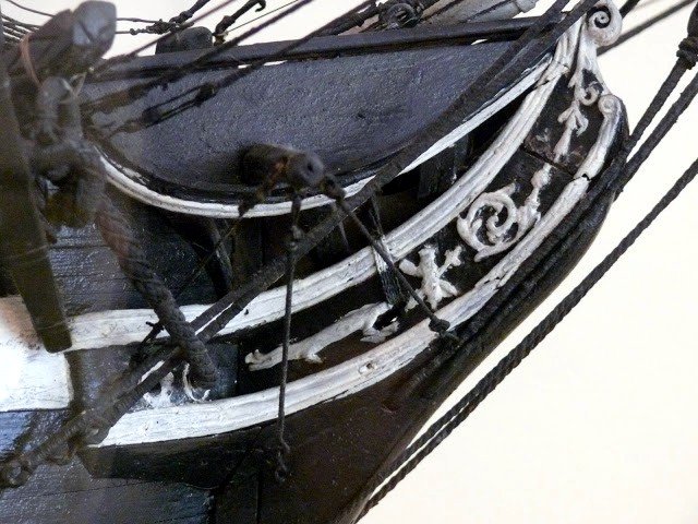
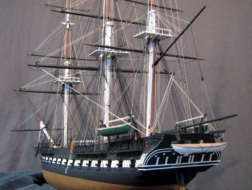
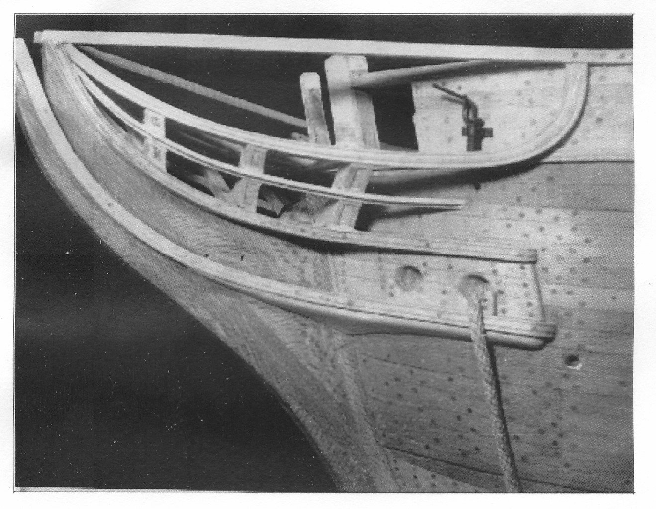
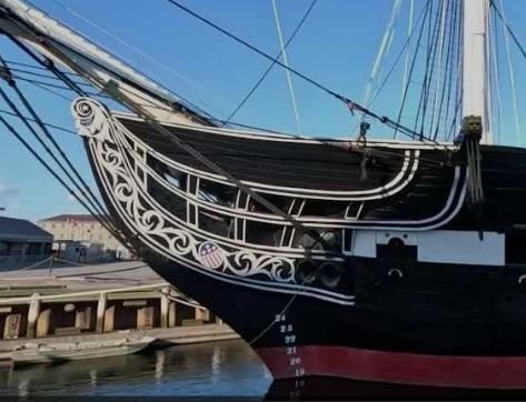
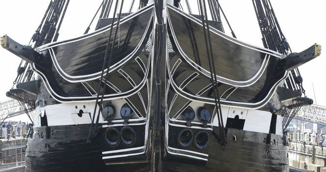
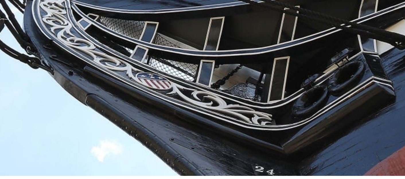
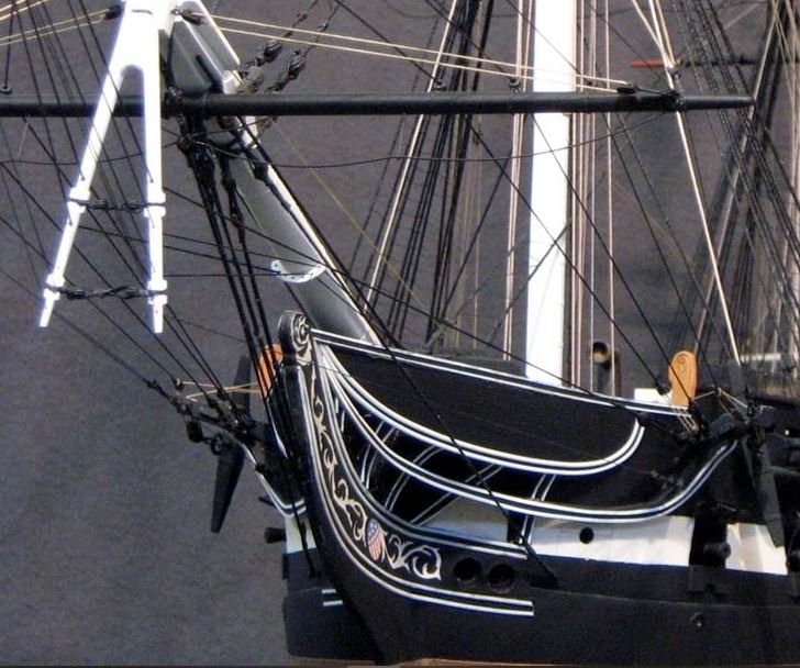
I thought it might be a good idea to give you a heads up concerning the pitfalls I encountered when doing the bowheads in case you are not aware of them already. The plans given on page 48 of the instruction book represent the restoration which was done in 1978 and is the current configuration. The scale is not given, but I was able to figure out that it is 1/96, and so can be used as is for the model. This configuration conflicts with the elevation plan in two ways: the cathead emerges from the hull at the forecastle deck level in the plan and in photo 24 on page 50, but does so just below the caprail on the real ship. Consequently the photo shows a "squashed" version of the bowhead structure compared to the real thing. The deck plan also shows the position of the catheads forward of their present position. I did not catch this until after I finished the build and saw that I had a foreshortened version of the structure. Here is a build photo of a superb model by Herb Ebson showing the simpler version of the bowheads shown in the Campbell plans: This is the configuration of the bows that the Revell model uses. The Model Shipways Constitution uses the current appearance. Perhaps one of the many builders of that kit might be willing to share the measurement from the stem to the cathead if you decide to use the plans given on page 48. By the way, the Ebson model uses real trennels, not simulated ones, and there are working brass sheaves in all the blocks. In case you do not already have them, here are some photos of the real ship you might find useful: Note the complex curves and variable beveling of the outboard edges of the bowhead timbers. Whenever I see a model of the Constitution, the first thing I look at is the bowhead. That is the most difficult part of the build in my opinion., and the Constitution bow is the most complex and challenging of any ship I have yet seen. The most successful rendering of this that I have seen is a build from the MS kit by Jerod Matwiy: One more thing. The cast metal trailboard provided in the kit is different from the current version, so some creative fettlin' will be needed to integrate it into the current configuration.
-
Amazing work! This kit demands great resourcefulness and creativity which you have shown. Congrats!
-
Thank you so much Ronald! I greatly appreciate your kind words.
-
Magnificent result! Congrats!
-
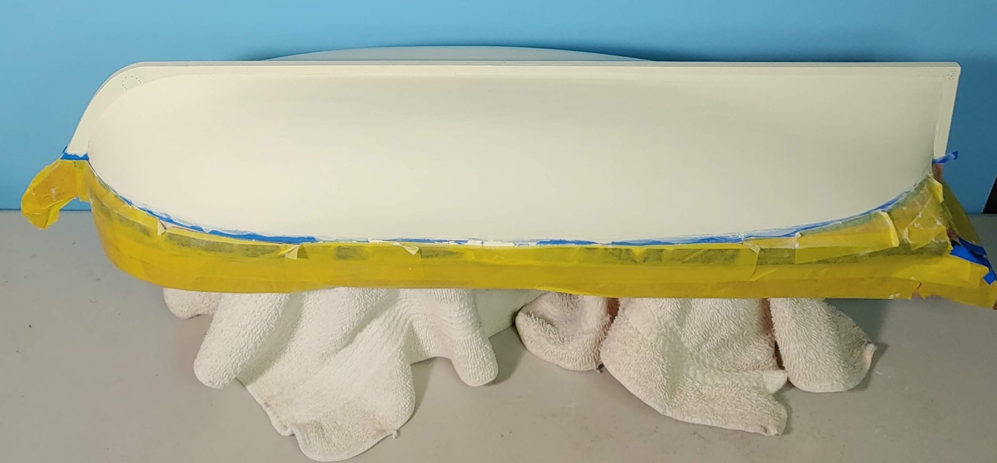
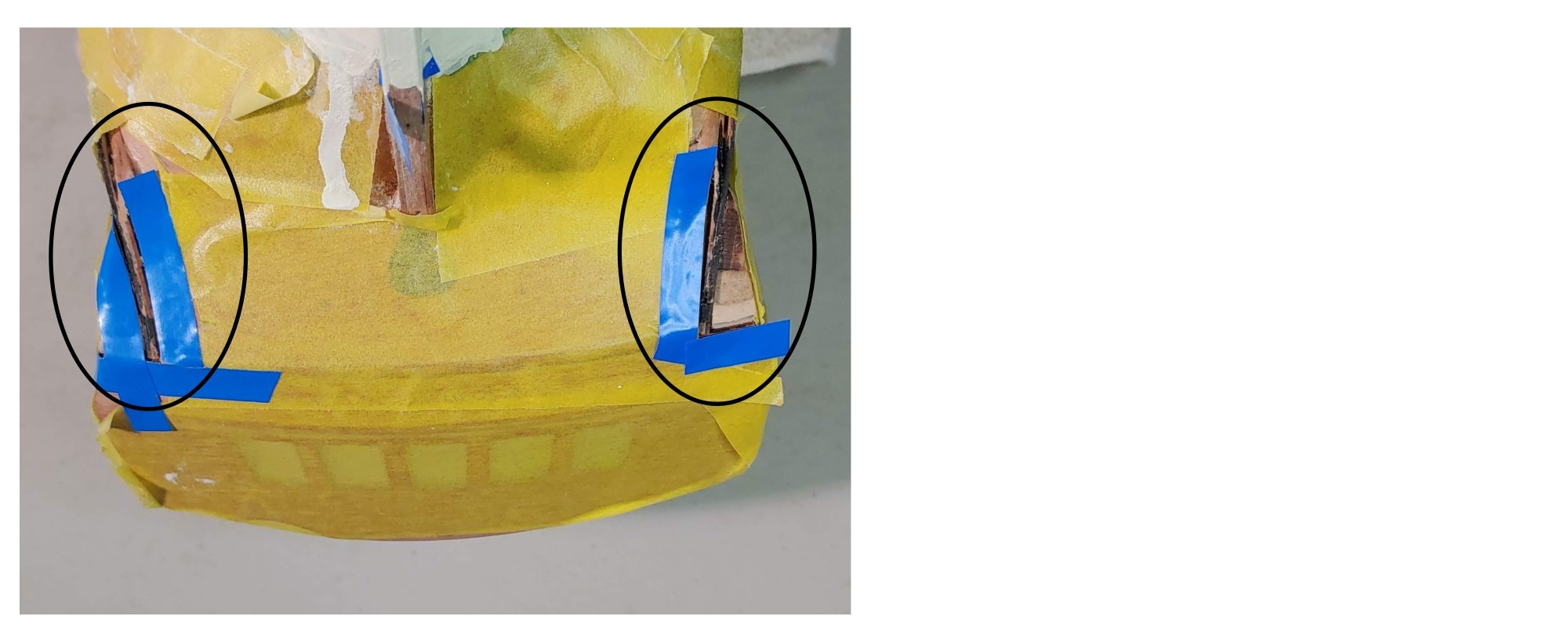
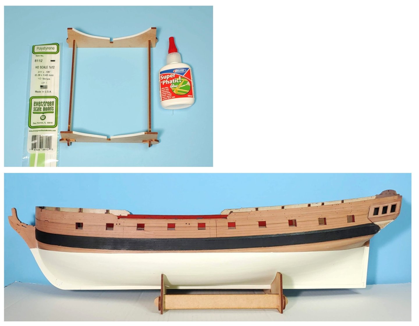
Hull below the water line filled, sanded, and painted using Deluxe Materials Wonderfill and Vallejo Ivory. I did not use a sprayer because I do not have the facilities for that, but I masked the rest of the model anyway because that fine white dust which is produced by sanding the Wonderfill gets into everything everywhere and I was concerned that if it got into the fibers of the pear hull planking patterns, I might never be able to get it out. Before I remove the masking, I should fill those crevices (crevasses?) at the outboard edges of the counter:


-
Looks like your arrangement for the sternpost and rudder will work. Best wishes for success!
-
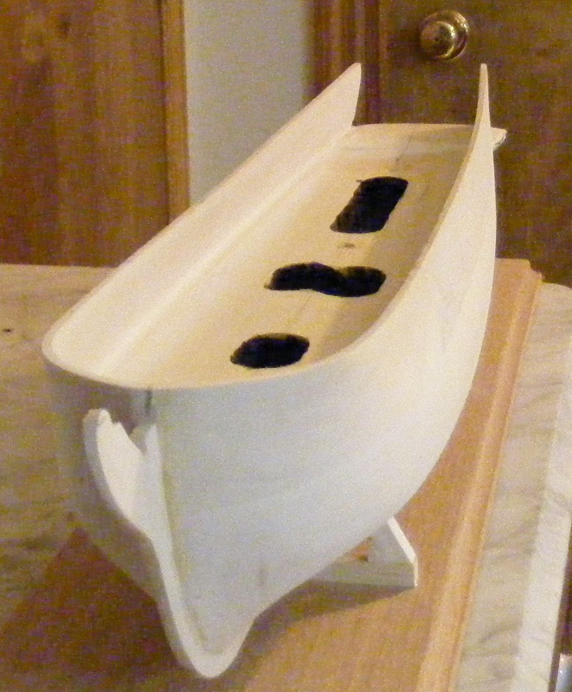
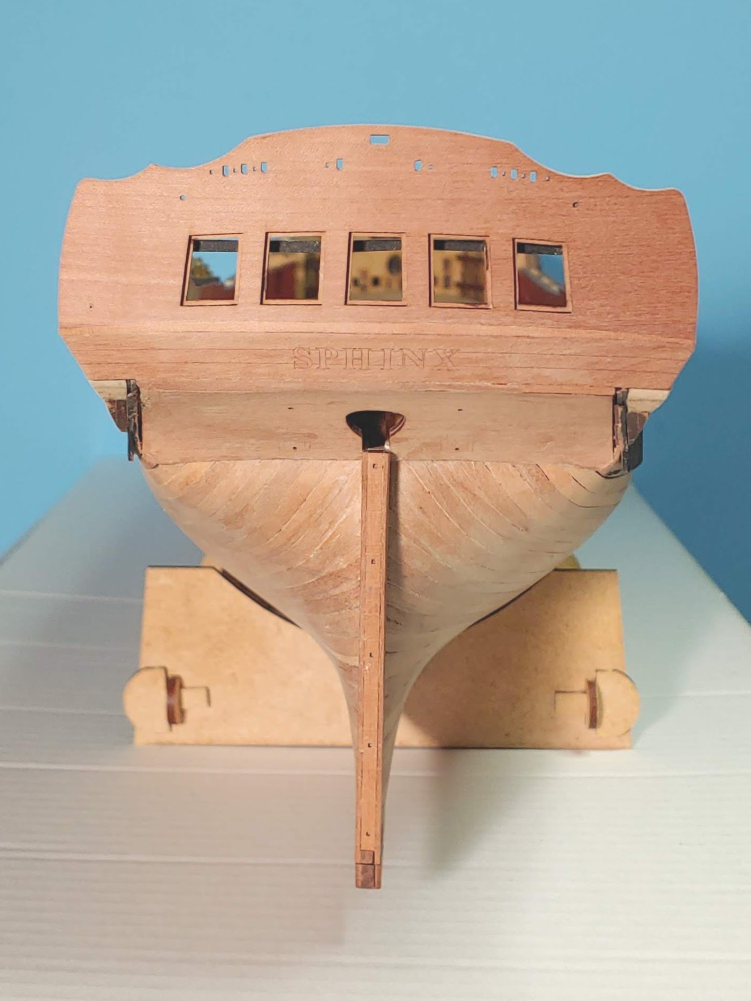
According to the instructions, a piece representing the keel is to be glued to the bottom of the hull carving. I did not shape my hull in such a way that the keel was a part of it. The stern post, keel, and stem with stem knee are all to be added after the shaping of the hull is completed. I wish I had taken a photo of the hull before adding the stem, but here is a pic of the hull showing the added stem and keel. You cannot see the stern post, but it is there: Having fallen into the trap that I described at the beginning of my log, I cut a large notch out of her stern and glued in a block, and worked from there. Unfortunately, I failed to get the shape right. It looks nice but it is not as accurate as I wanted. It is too sharp below the waterline, especially at the bows. Looking at the photo of Lawrence Arnot's build which appears on the title page of the instructions, I see that he did not get it right either. His is too bluff. If I were in your position, I would contact BJ to see about the possibility of getting (buying?) a new carved hull, but that is because I do not see a way of adding enough material to correct your problem. I am not that experienced, so maybe someone can suggest a solution for you. Perhaps Nic at BJ can suggest a better remedy.

-
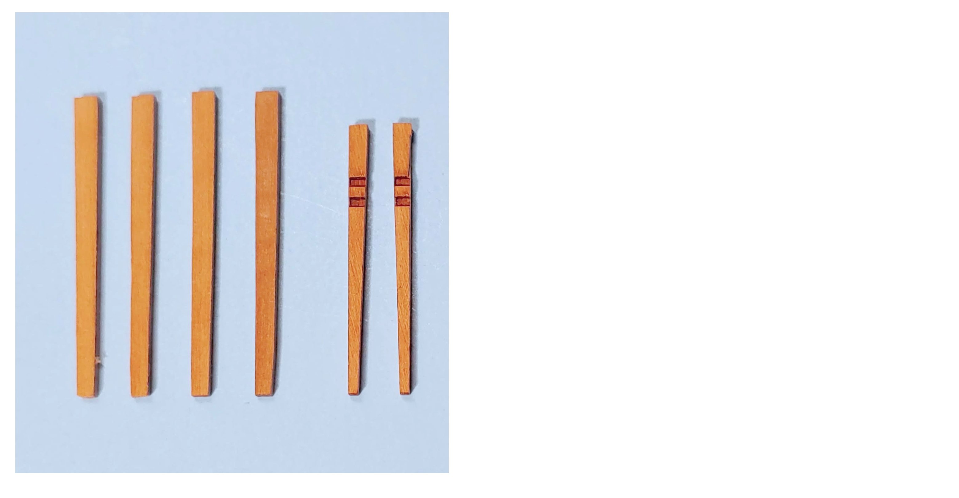
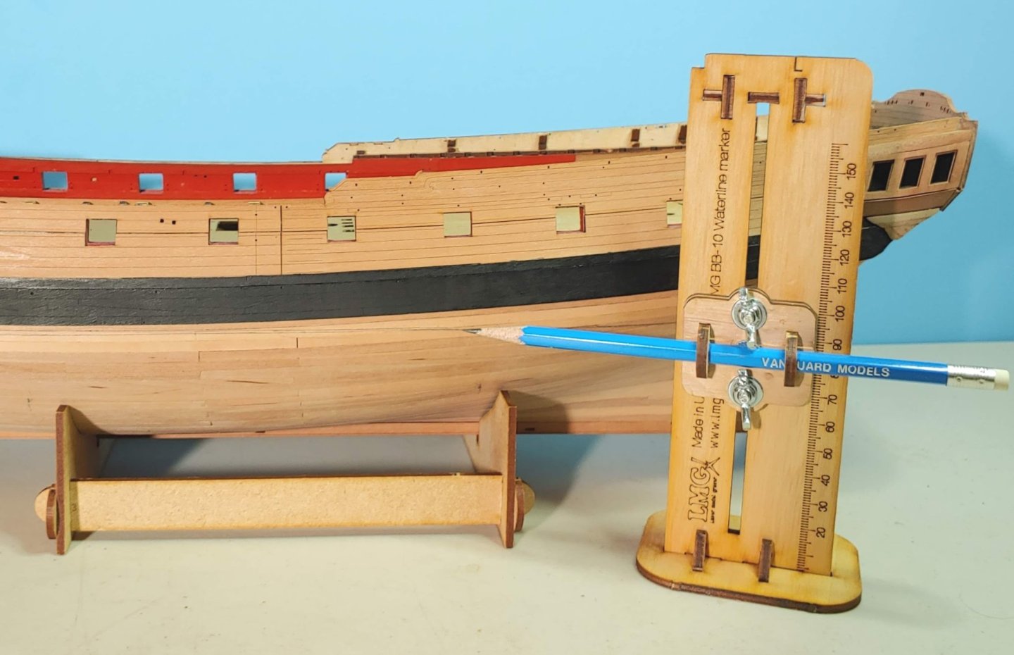
Having completed the basic structure of the stern and quarter galleries, I thought that it might be a good idea to take the rails from their sheets and position them as well as possible on the stern without gluing them, referring to the illustrations available from the instruction book and other builds, to make sure that all components will coordinate properly. It is important that the stern rails and quarter gallery rails line up precisely. I see in the instructions that the upper stern rail sits immediately beneath the windows. I found that if I put it there, it will not cover the gap between the stern fascia and the upper counter. I also found that if the lower rail sits over the gap between the upper and lower counter, that the corresponding rail on the quarter gallery will sit too low to allow enough room for the PE decorations. Accordingly, I have filled both these gaps to allow myself maximum flexibility when the time comes to install these rails. There is quite a bit of filling and fettlin' to be done on the aft side of the lower quarter gallery finishes, but I think i will do that during the next phase when a good supply of diluted filler is at hand. The next step is the drawing of the water line. I looked at various devices for doing this and decided on the Vanguard version as it holds the pencil more firmly and has a scale printed on it which saves a lot of guesswork. If I had been smart I would have decided this before and ordered it along with the boat kits saving quite a lot on fees, but there it is. The next phase involving filling, sanding, and painting of her bottom will likely take some time. By the way I am considering a 50-50 diluting ratio for the filler. Am I right? I am also considering an off white - Vallejo Ivory in this case rather than the bright. Keith Julier in his books "Period Ship Kit Builder's Manual" recommends Barley White. I checked it out on line and found that it is a bit too dark for my taste. I have bright white paint, so if do not like how the off white looks, I can always repaint it.

-
Actually, if you took those parts out of their bag, laid them out and photographed them, they might look familiar to me after all. I am sure Nic would be glad to help you out. He is always so helpful.
-
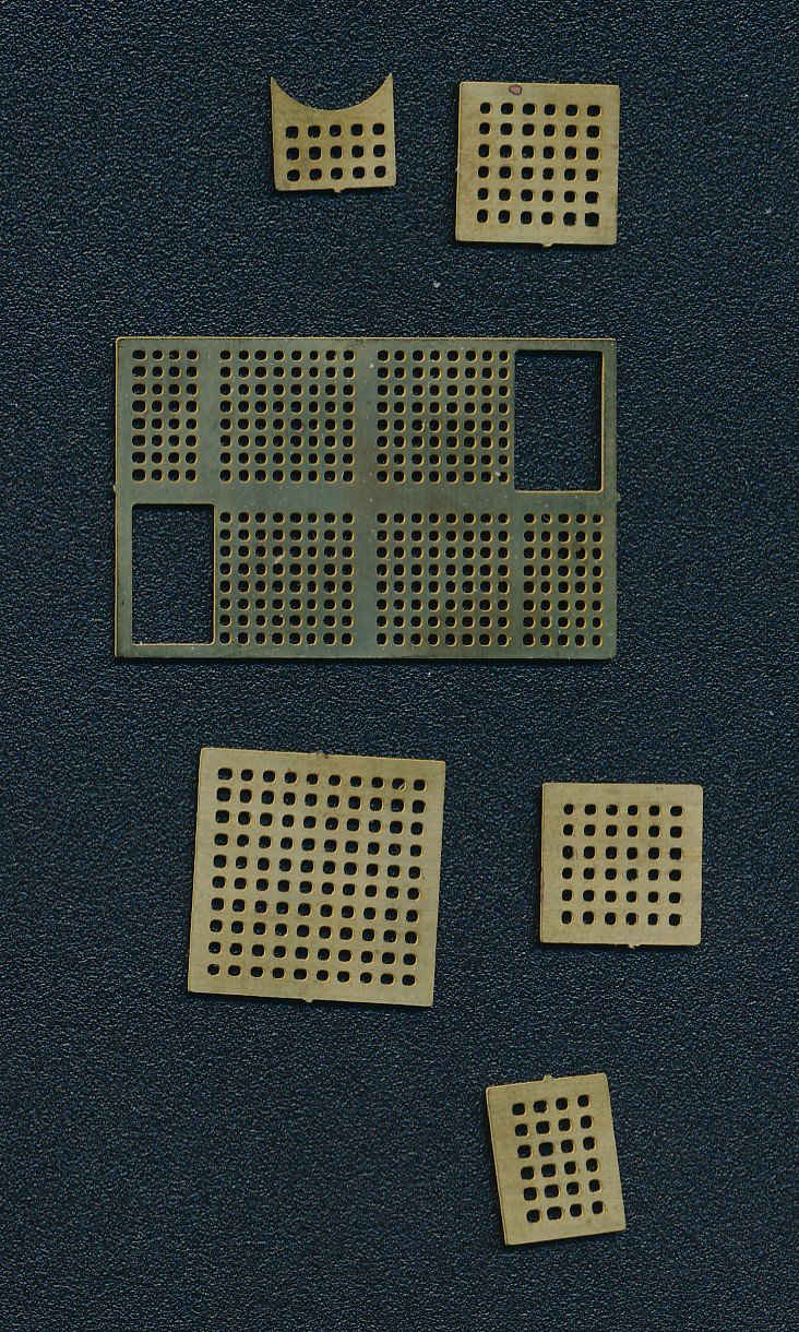
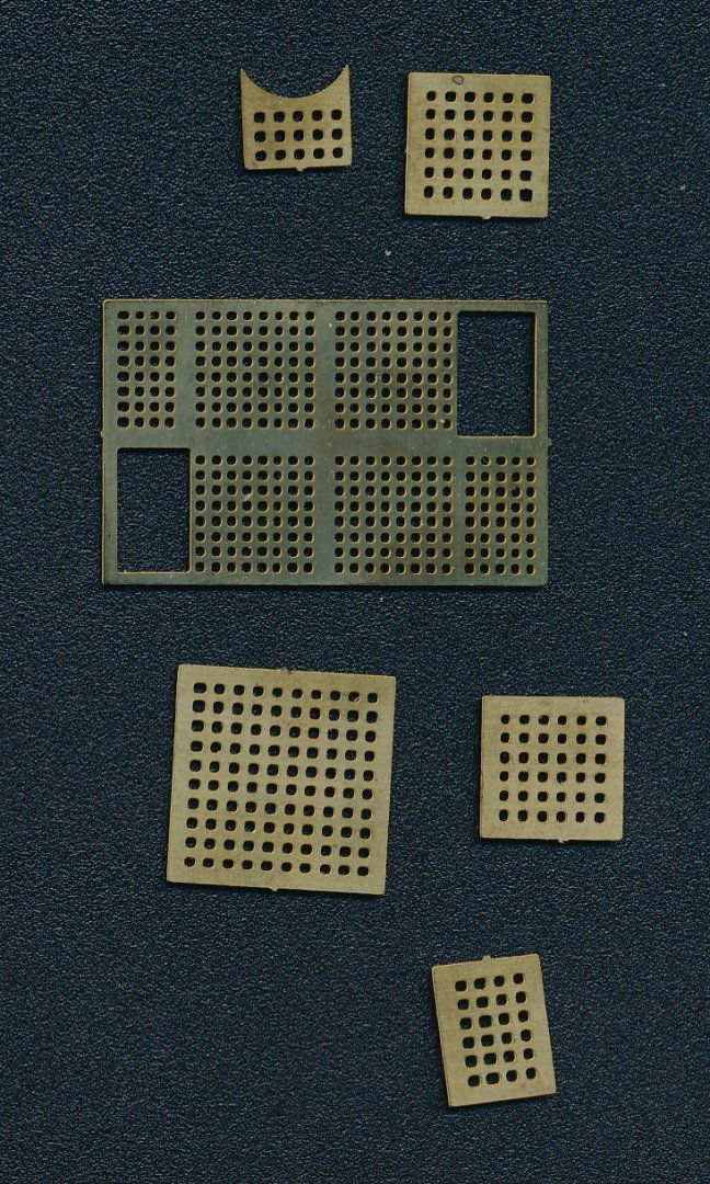
I did a scan of the grates provided by BJ in my kit. You can see why I say they have round holes to represent the spaces between the battens. They should be square, but they are closer to being in scale than the strips I used. As I said, If I had to do it over, I would use these. The brass PE parts in your picture do not look familiar to me. Perhaps the kit has been updated since I bought mine.
-
Gratings consist of strips of wood interlocking together leaving square spaces between them. The PE gratings provided by BJ had round spaces instead of square ones. I ordered grating strips from Model Expo which fit together egg crate style, similar to the cherry ones now offered (#MS0332), but larger. There is a photo in the post to which you refer which shows one of the strips, and and assembled grating. These are out of scale, and if I had it to do over, I would have stuck with the PE ones even though they do not really look like grating. I believe that I still have those PE gratings. If you like, I can photograph them and post them, but I believe you have these, and can see for yourself that the spaces are round instead of square.
-
Thank you Mark! Murphy's law is a factor in much of what we do.
-
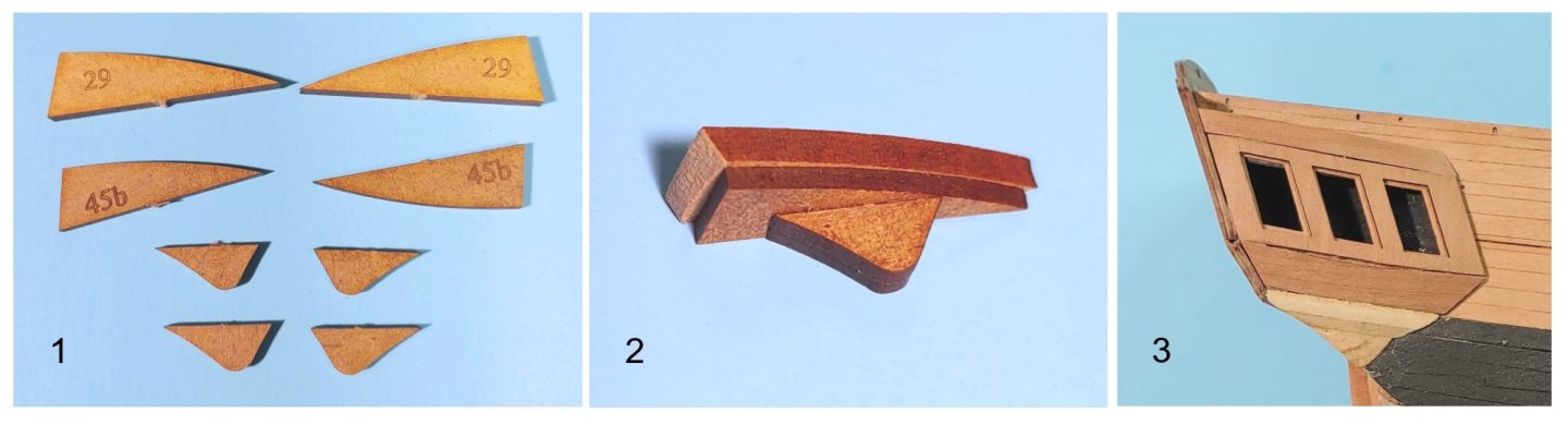
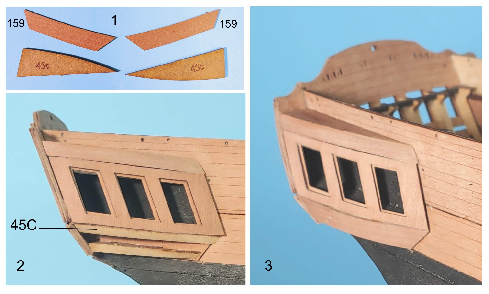
Work on the quarter gallery continues: 1. Quarter gallery patterns and quarter gallery berthing patterns. 2. Quarter gallery patterns 45C are shaped then glued to the underside of the lower part 45 to act as a bearing to which the berthing patterns will be glued. 3. Quarter gallery berthing patterns glued in place. Next up, the lower finish: 1. The MDF lower finishing patterns. 2. These patterns are glued together while holding them in place against the hull. 3. The assembled parts shaped and glued in place. I think I will leave them unfinished in case further refinement of the shape is needed when the rails and ornamentation are installed.