robert Lamba
-
Posts
93 -
Joined
-
Last visited
Content Type
Profiles
Forums
Gallery
Events
Everything posted by robert Lamba
-
No problem Pete, clutter away. Each build should be an aid to the entire community any information or discussion here contributes to the knowledge base.
-
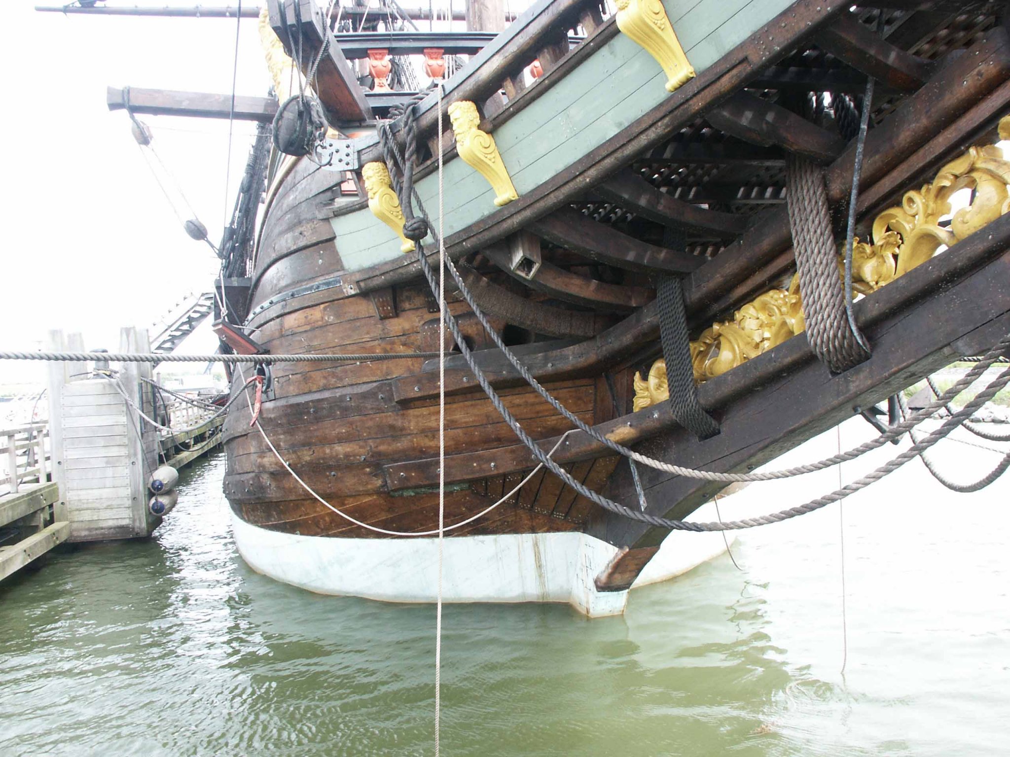
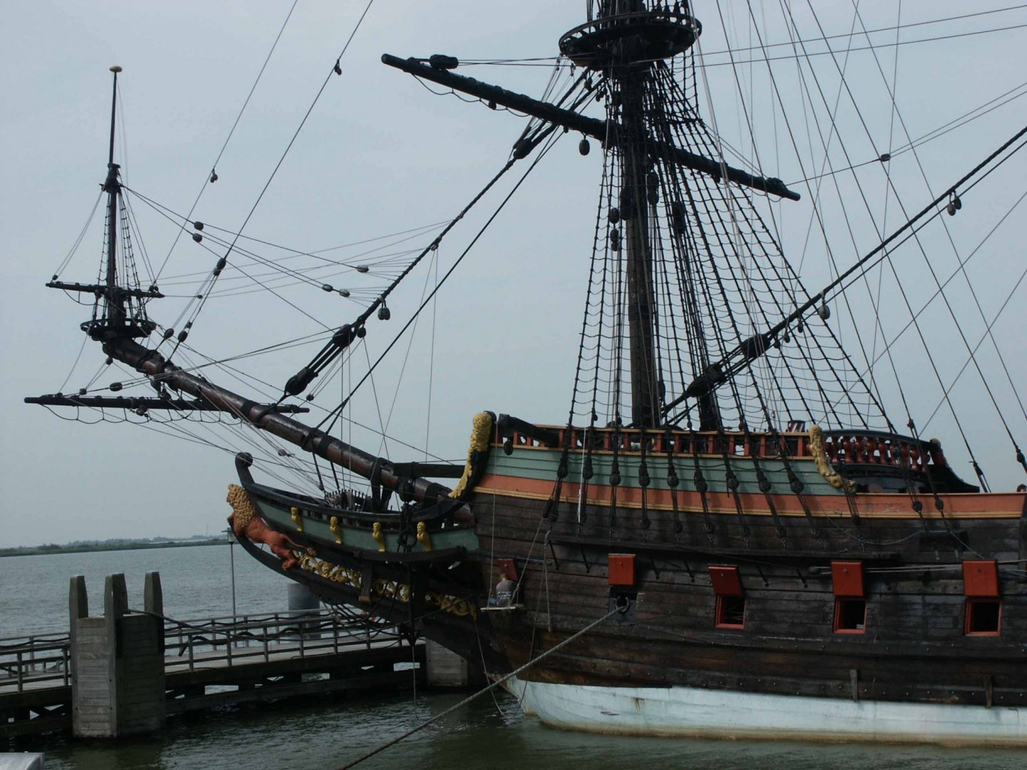
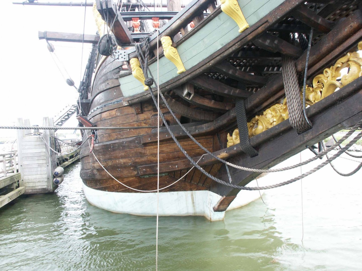
Kit manufacturers may make alterations to the plans but from my understanding all DerFflinger plans originated with the same person, I've come across his name in the forum. My Dikar plans are about 40-50 yrs old. As Pete and I have progressed through my build we've found some of details in the plan had to be incorrect. As no one has actually seen an actual Fluyt the best reference we have is the full size reproduction VOC Batavia in the Netherlands. Even in that example no doubt built with the best historical resources available there are errors and deviations. Add to that the various shipbuilders of the day would've built to their own specifications and not to a fixed design, modifications and innovation would be routine. VOC Batavia
-
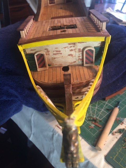
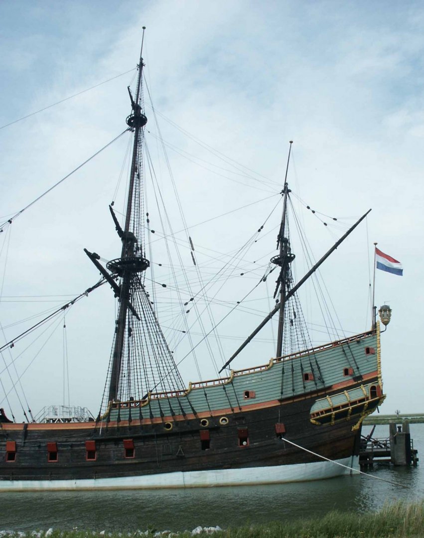
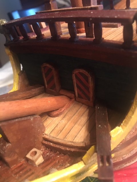
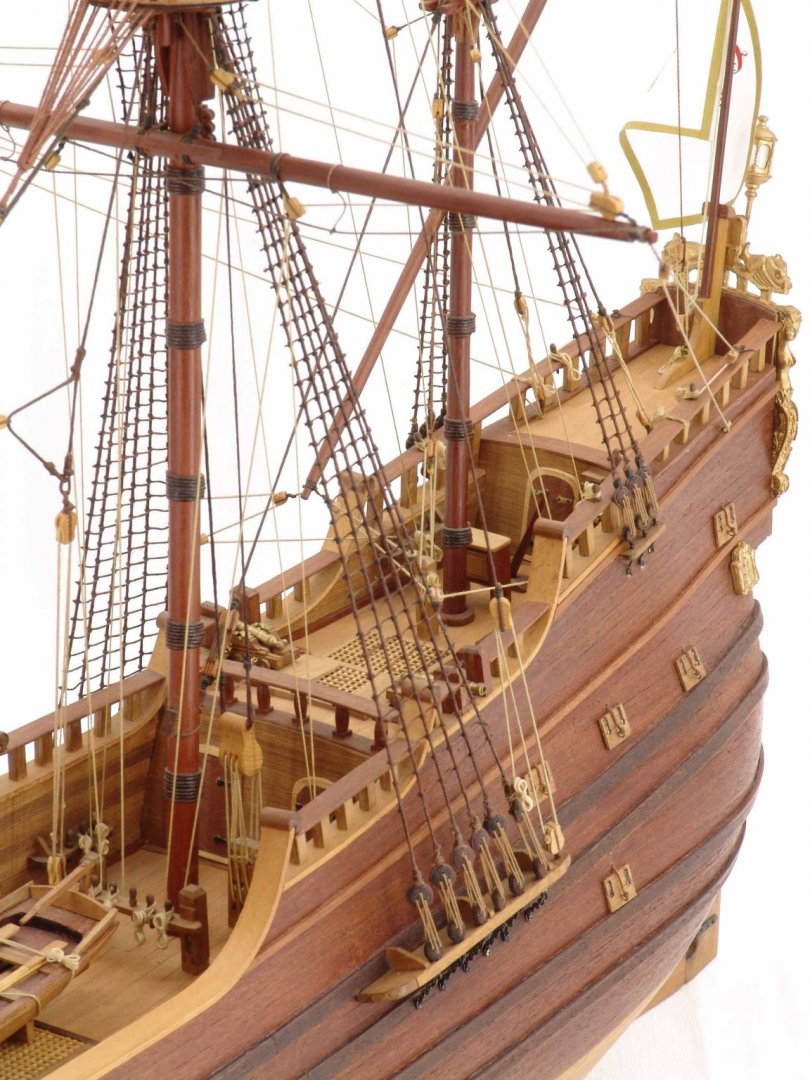
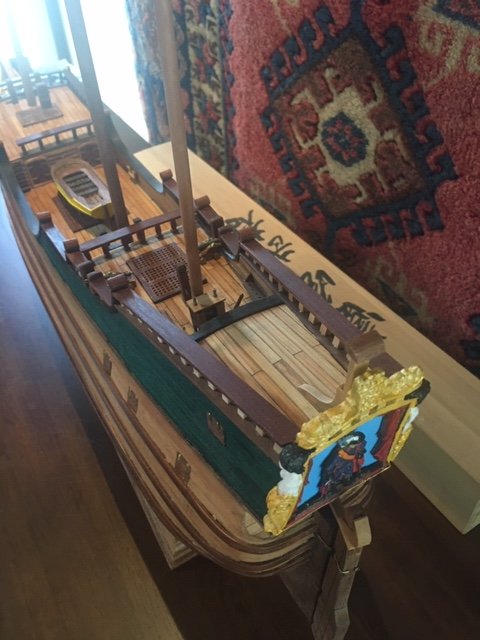
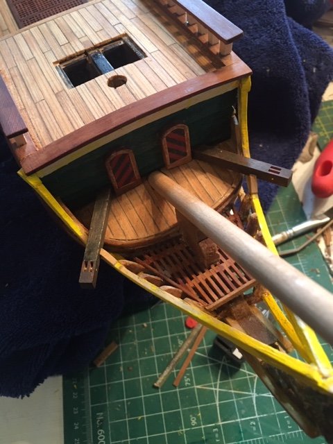
After eliminating the quarterdeck cannon the cannon ports in the quarterdeck cabin became an issue. It was extremely improbable for two cannons to placed in such a small space. With no grate above or ports it would've been a cabin devoid of natural light. Using the Batavia as my guide I decided to convert the ports to windows, the only difficulty being their size which was considerably larger than a window and my reluctance to remove considerable amount of clinker to reduce the window size. I had two decorative pieces that were initially meant for the hull which were conveniently the same size as the ports. With a little red paint to the now window shutter and gilding to the now decorative window frame they're acceptable representation of windows. Not ideal but I think it works.
-
After a lot of research and consult with Pete we reached the consensus Fluyts most likely never had cannons on the quarterdecks. So the decision whether to build an unknown gun platform or not to work around the quarterdeck grates was rendered irrelevant, I removed them completely.
-
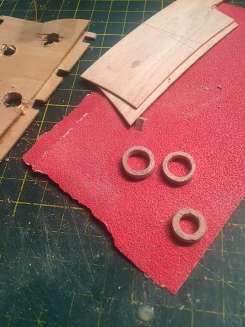
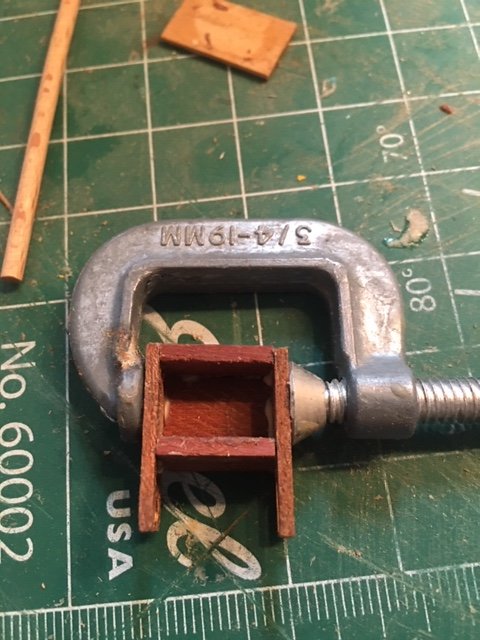
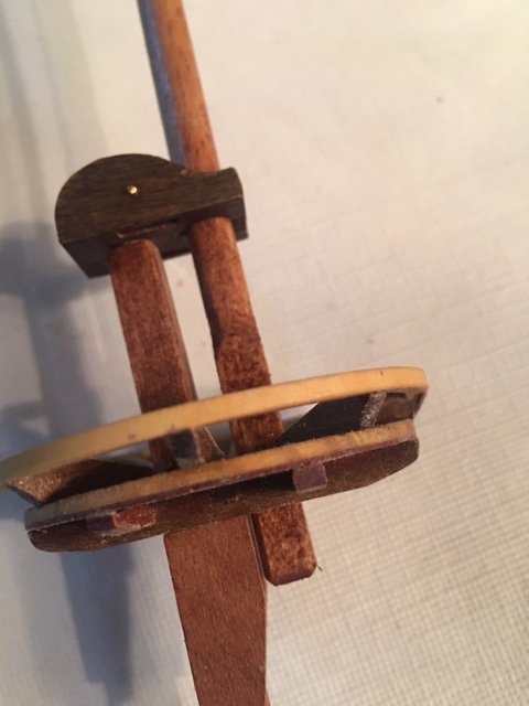
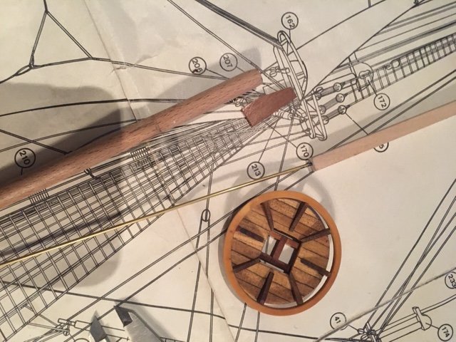
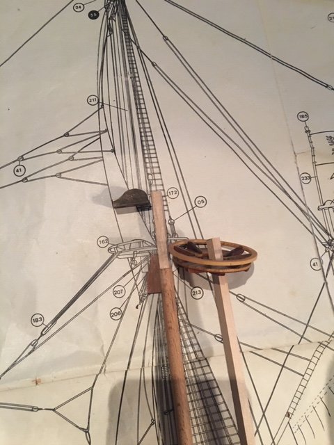
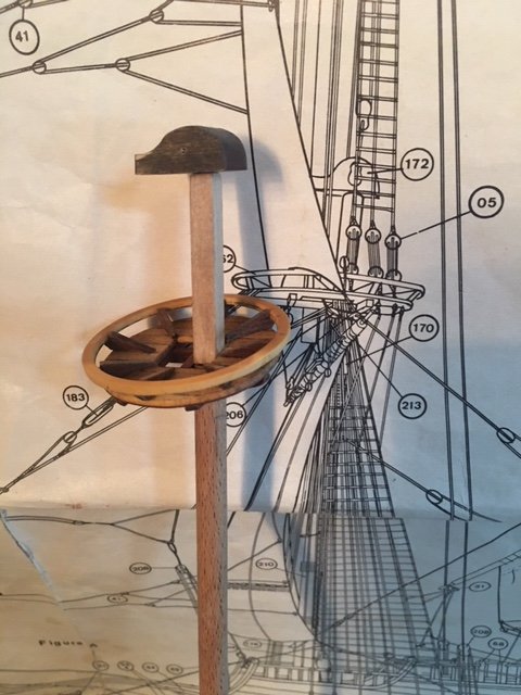
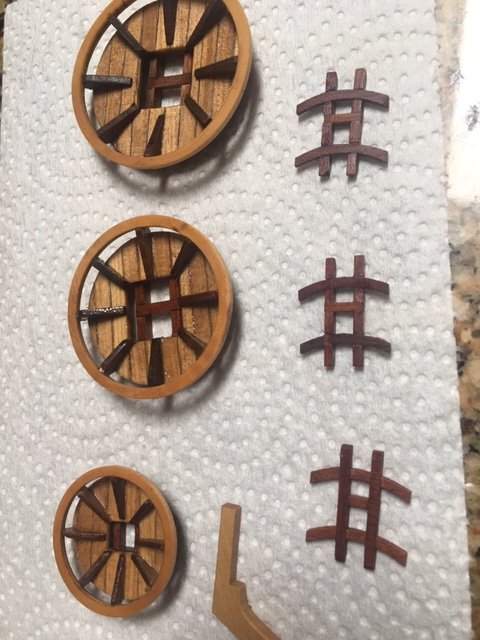
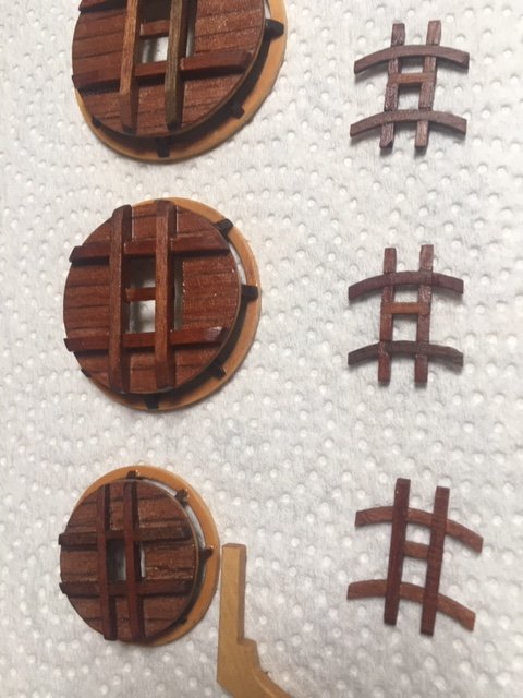
Still mulling over my cannon space issue so I proceeded to another challenge put to me by Pete, mast collars. There was no allowance in the kit for mast collars so I needed to build them from whatever I could find. Technically making tiny wooden donut is not something I've done before, if it were bigger a power drill, hole saw and bit would accomplish this in a couple minutes, a collar 3mm x 15mm is another matter. My first attempt was to drill a hole slightly small that the mast in solid 16mm stock then cut down the material around hole it to 15mm, that didn't end well. Then I thought I'd laminate extra plywood parts in the kit. First attempt to drill a hole ripped the lamination apart. Try again with stronger adhesive, plywood held together but drilling holes always resulted in splintering of the plywood. So back to the solid material, I drilled my hole further along the material to avoid splitting the wood but the large bit would wander from centre. Next I drilled a very small pilot hole, then increased bit size in small three increments, reaming the opening to approximate size rather than drilling. Success! After forming the hole I could then cut down the exterior dimensions approximately with a knife, a file to to remove rough edges and reach final dimensions. A rolled up piece of sandpaper to slowly enlarge interior to the mast diameter. The rings were by now very fragile, a very cautious sanding reduced it to final thickness and a final camfering of the exterior. The Bowsprit collar required a completely different approach but the learning curve had been established with the other collars, the mast entering at the junction of deck and bulkhead required a two piece collar. Now I await the next fabrication challenge Pete is going to suggest.

-
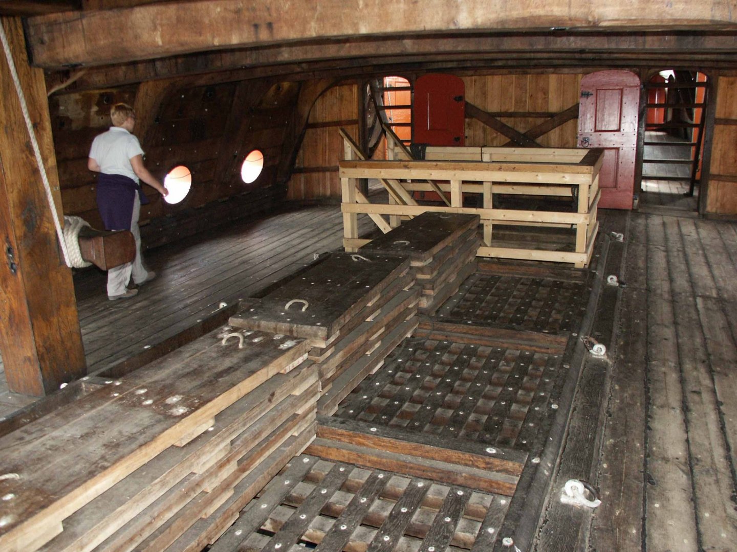
The grates are firmly glued in place so reducing the height to flush to the deck is problematic. Again my conflict is I'd be trading one historical inaccuracy for another. Perhaps a combination of the builders solution on the Euromodel kit with what I see on the VOC Batavia website. The Batavia has removable panels that can cover the grates converting them to a solid surface and can be stacked for ventilation and light when required. I have sufficient U shaped material to create a platform beneath both cannons, perhaps a removable cover for the grate behind the cannon like Batavia's? I would need to add some material to the grates to simulate the receiving frame for the covering panels.
-
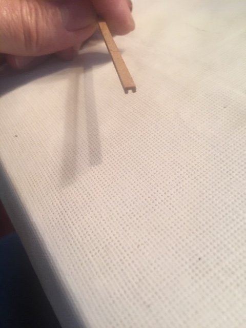
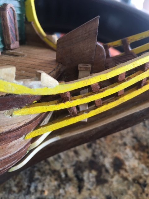
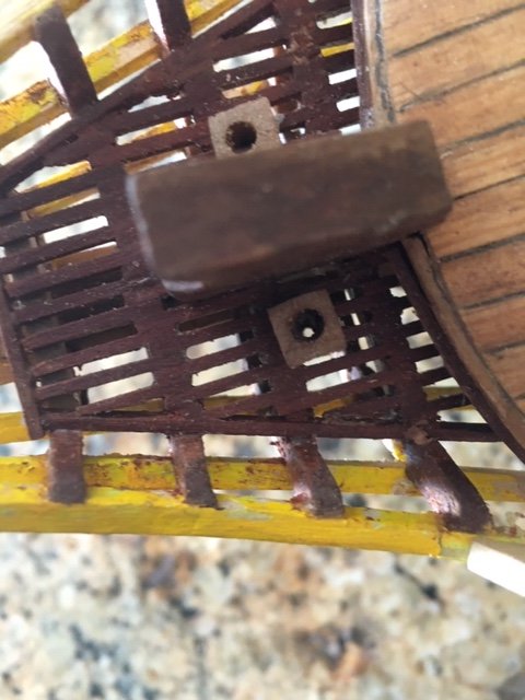
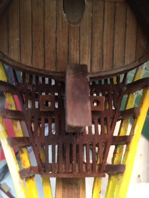
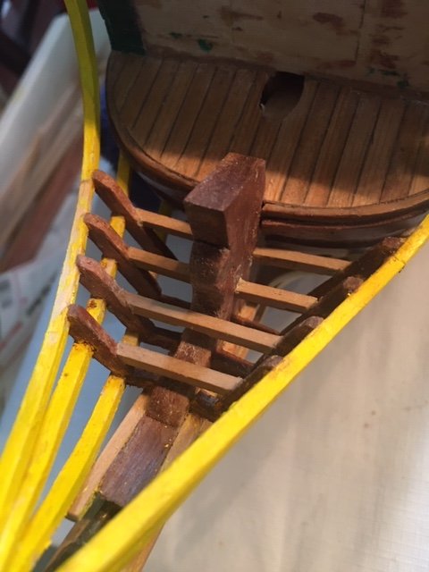
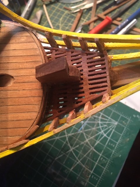
Next project building gun platforms. Earlier in the thread I mentioned the problem of the grating interfering with the loading the guns, they couldn't be returned to be loaded as it is now. Even if I had eliminated the grate there would've been insufficient room. Lowering the grate flush wouldn't have solved my problem because it raises another issue, the grates were raised to keep water out. If I was concerned with accuracy doing that I would've replaced one defect with another and I'd be no further ahead. I could leave it as is and no one I know would be aware but it annoys me. I know historically merchant ships have often been pressed in to service when needed and modifications were made to upgrade them to a higher battle capability. In doing so there were design configurations that made do with a bad situations. So I tried to think like a ships carpenter, "How do I add two cannons to space not large enough to accommodate them and still allow water to clear the deck". I had some material left in the kit that I can't identify and unless someone can here can tell me what it is it offers a solution for my gun platform. 3mm in width with a 1mm channel, it's height is conveniently the same as the grate. Laid side by side with channel facing down from the grate to railing it would allow the cannons space to retract and not hinder water clearing the deck. . I've searched the internet and I've found instances of raised gun platforms just not for this design of canon or time period, but is building a historically unverified platform a worse error than a cannon that can't be retracted, it's not as if I'd be using an unknown technology for the time period. I did find one other builder of this same ship that also saw the same issue, he/she also built a raised platform and from what I could see without allowing for water egress. The same Derfflinger but it's a Euromodel Kit mine is a Dikar, that builder partially covered the grates with the gun platform, I intend to butt into the side of the grates.
-
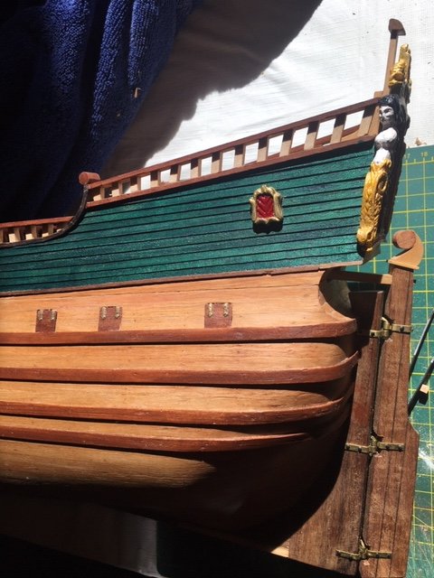
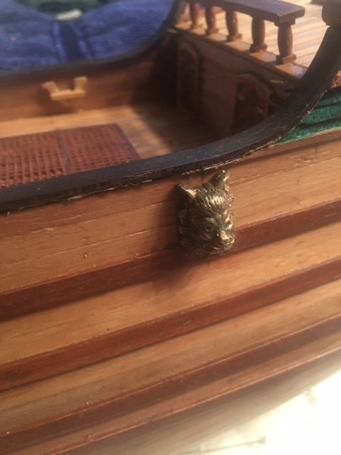
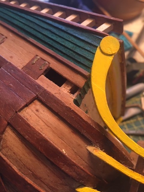
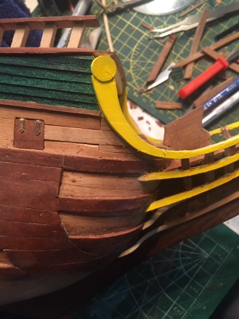
I had nice couple days away from my ship build, after a long cold winter it was time to enjoy the warm sunny weather with my motorcycles. Today it rained 😫so back to the ship. Installed these " things" I forget what they're called, I think Pete called them "cross---". I've seen them on other builds and they didn't appear to serve any purpose purely decorative, on my plans they show a line fed through them from the lower main mast sail. I was leery of cutting through the wale to install them but with my new tool kit I found just the right blade and slow careful carving i got the job done. The hole for the line emerges 2mm above the deck fore of the staghorn which I assume is where it ties up. Most difficult part was removing a drill bit that broke off in the 2nd one, it took a half hour with a Dremel grinding away the backside before I reached the bit and could tap it out with a punch.
-
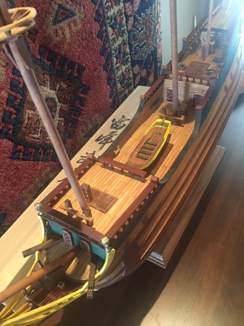
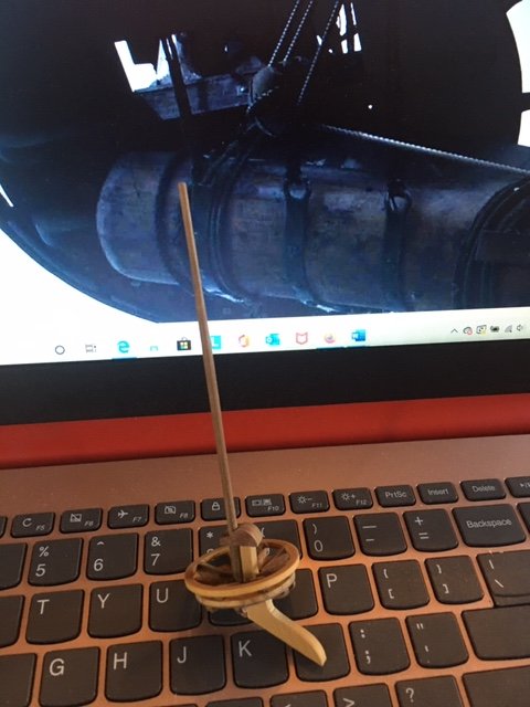
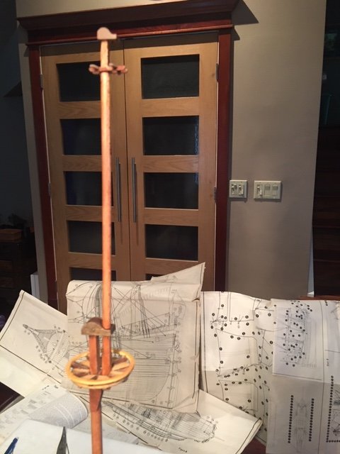
Summer is here motorcycle season my other time consuming hobby. I'm very nearly done with everything hull related and then it's masts, yards and rigging. I'll cut back on ship hrs until October when I concentrate fully on the rigging. I may spend a few hours each week preparing for that. I've found my dry dock for my build, the stand is flimsy I'll need to address that before it ends in a disaster.

-
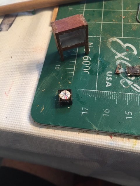
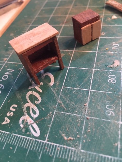
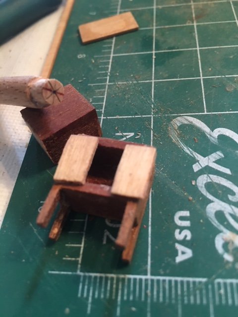
Compass box and finished binnacle. Probably not historically accurate but as can't find anything definitive from the time period it'll do, better than what was in the kit. I put a brass finish on the side of the compass which was a waste of time as it's not visible once in it's gimbal box and tucked inside the cabinet. I feel better for having done it, it wouldn't have taken much effort for Dikar to have done the same.
-
here is where I am with my binnacle, already an improvement. I borrowed the side panels, top and doors from the original, made a compass on the end of a dowel. Searching the internet for actual binnacles for examples of door/glass options and lighting. Original solid bock of wood. Left over railing was perfect size, I only needed to square up the cabinet. A vast improvement Imo Compass, not sure about final door layout as yet.
-
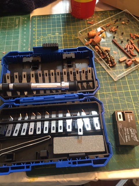
Went out to buy some supplies this morning at my favourite auto supply store and I found this kit! $11 for a knife, 26 blades, sharpening stone, tweezers in a handy box vs $15 for the 15 blades in the box on the right at model supply store.
-
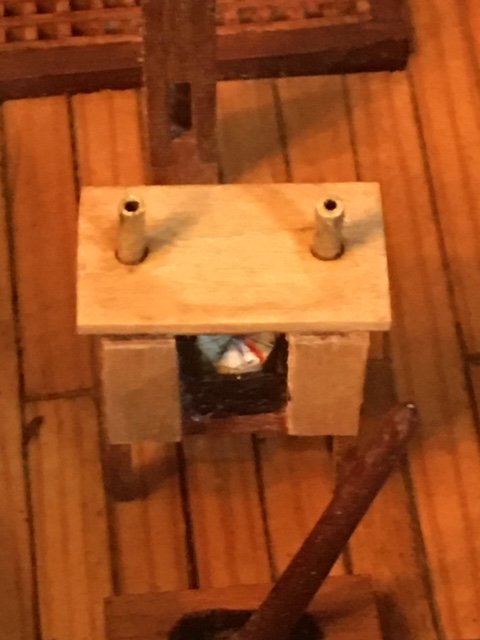
Seat of ease installed. Did I really need to have a functional toilet, no but it was satisfying to complete.
-
Your binnacle has given me inspiration to improve mine, I had no idea what it was when I put it together or how a binnacle worked. Assembled it was just a block of wood with legs, that didn't sit well with me but I didn't think there was anything to be done. I give it a shot and try put a compass and light in it, if succeed it'll be almost impossible to see, I'll probably be the only one that notices.
-
You may have already come across this link to photo's of the Batavia on the internet, I've consulted the photos extensively as a reference for my Fluyt build. When in doubt consult the actual ship by built by experts, being able to click and zoom in on various details of the Batavia has been a great aid. https://www.modelships.de/Museums_and_replicas/Batavia/Photos_Batavia.htm
- 136 replies
-
- 2
-

-
- kolderstok
- batavia
- (and 1 more)
-
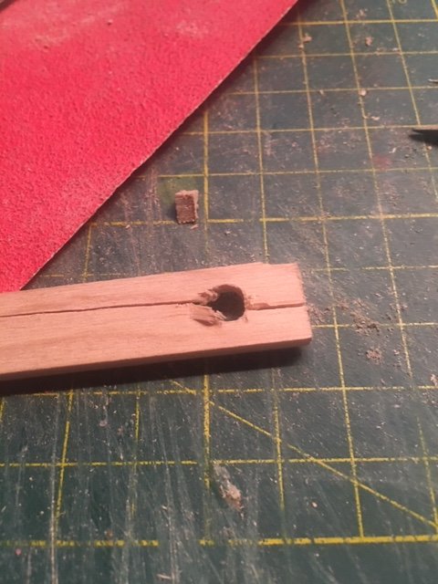
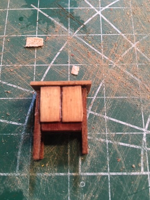
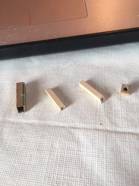
Seat of Ease/ toilet. I saw a picture of it on the Batavia but never on a kit so why not make two. Seats themselves weren't too difficult the chutes were trickier. Trial and error making the chute my first thought was a small 2x2 mm up through the prow, it worked but it was just a random stick out of place where it was. 2nd attempt was making a square chute from clinker material, too big(on left in photo). 3rd attempt I thought I'd just drill a hole into the end of 4x4mm timber and be satisfied with that. With the drill set on it's lowest setting it was going well and straight so I thought why not keep going. I probably didn't need to make them appear functional but I feel satisfied I succeeded. I managed through luck not to drill a hole in my hand and succeeded in making the chutes. Install comes tomorrow.

-
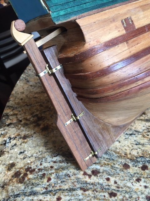
Assembling the Sprit mast, top, knee and mast cap gave me problems, no illustration and a mast cap that was no where near required dimension. With help from Pirate Pete I finally got by that this morning. Done and ready to attach to the Sprit. Yesterday I assembled the rudder, the kit should've had four hinges but there were only three in the kit so that's what I went with. And no hinge pins were in the kit so did my best with brass rod, not the best but I doubt anyone will notice. I'll be done the hull this week! I never thought I'd ever get to this point, very few parts left in a small box. I'm now attaching all the tiny delicate bits that are so easily broken off during construction. A little bit of paint, stain, oil and clear finish and I'll put it away until the fall when I progress to the rigging.
-
Main mast fitted together, only needs a little sanding, stain and clear coat. Joins all hidden by either Cap or Top. No adhesive yet, 24 hr Gorilla glue to be applied when the foremast is complete and when I'm 100% sure I haven't overlooked anything.
-
Who knew masts could be such a pain! I thought I was finally moving into easier territory. The masts would be straight forward, round poles with a taper what could be so difficult. I did wonder how the builders fixed the masts in place there would've been tremendous torsional forces involved. Pete confirmed my suspicion, square masts. So a seemingly simple task became much more complicated, joining a square mast to a round mast. I've a limited amount of material so there wasn't any room for error. I laid it all out on the floor and studied it carefully for an hour(wife thought I'd fallen asleep), lot's of options. How do I shape a round mast into a square peg accurately? Pete suggested pinning a square section to the mast, pinning worked when I pieced together the bow's top rail so that's what I went with. I haven't determined where the joinery should take place, at the Top or below the Top between the cheeks, there are structural issues pro and con to think about first.

-
I wasn't intending to move on to the masts as yet but to finish the bow section meant addressing the sprit and doing one led to the others so I assembled the tops and crosstrees. Once again no instruction manual and no accurate illustration created a puzzle. With Petes guidance we solved it and 12hrs of work later I think I'm ready to move on to tapering the masts and fitting assembled sections. They may appear a bit glossy but that's because I just pulled them from a oil bath and drying before I apply a flat clear coat.
-
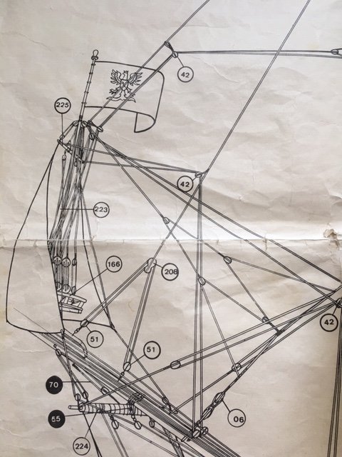
I'll be moving on to cutting a slot for the gammoning lines. The my Dikar plans and many reference materials call for the cutting through the cheek rails but I have reservations doing that. First because it's precise work in a tight spot that can go wrong, easier is always tempting. Second, wouldn't cutting them structurally weaken the cheek rails, I assume structural bracing is why they were there to begin with. Anyone have any thoughts for or against cutting those rails. I couldn't help but notice the builders of the contemporary Batavia didn't cut it's cheek rails. I've noticed an interesting alteration on the contemporary Batavia, the cathead is open on the end, and no cat face.
-
Encouraging words from more experienced builders are always appreciated.😁 My final solution for the catheads. While constructing the head I spent considerable time contemplating my problem of installing two doors and catheads immediately above the area of the head. Moving the catheads to the deck of the forecastle like the VOC Batavia looked like a historically acceptable solution. But when I closed off the area between the deck and the top rail it still left a section of the deck without a railing which would still be treacherous for anyone venturing there, the Batavia has a higher enclosed top rail. A pair of catheads mounted on the top rail would provide a safety barrier, so now what, move the catheads back, lol. Consulting some period paintings of time period the two doors on either side of the bowsprit appear standard. Then it occured to me that I was guilty of once again not thinking outside the box, I was accommodating the two ornamental columns in the original plan from Dikar. Ditch the columns and replace them with doors! I'm embarrassed it took me so long to see the answer.
-
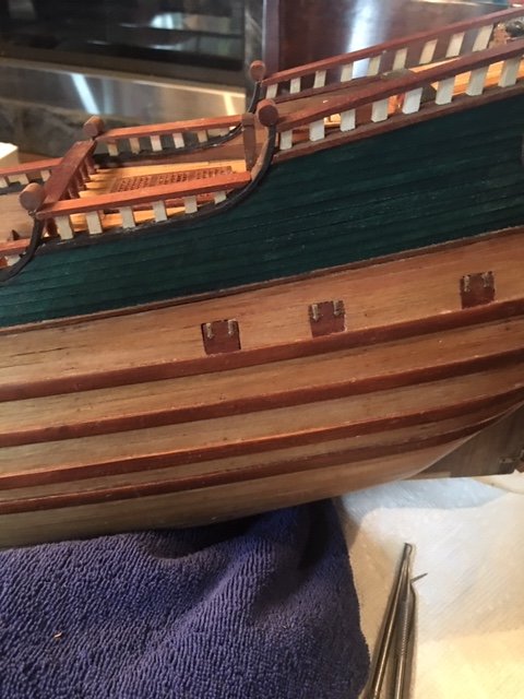
Today I addressed another what think is a flaw in the plans, the large gap between the top head rail and the deck. This was a working area of the ship that also served as the crew toilet, it seemed to me as strange to have such a large gap where a crew member could easily be washed off deck and it didn't look finished. But what did I know someone more knowledgeable than drew the plans decades ago, the plans must be correct. Consulting historical paintings and references sources consistently show gap is closed off, strake are brought forward around the bow filling the gap under the head rail. I only needed to pull one strake from in front of the gun port to give a staggered appearance, not perfect but when completed there wouldn't be many people that will pick up on the change. Imo it vastly improves the ship profile in that area.
-
Head construction was undoubtedly my biggest challenge so far! I knew it was warned by Pete that it could be tricky and complex only more so without the build instructions. I lost count of all the hours I put in over the last week. Three steps forward two steps back, assemble, disassemble and then repeat!, Not enough hands and excessively large fingers, down one with a self inflicted stab on the index finger. Improvising on materials when the correct ones weren't included with the kit. With advice from Pirate Pete and internet photos of other builds and consultation to period ship builds I discovered in my own library I have finally reached an acceptable prow. I can see my errors where it can be improved for my next build but I'm reasonably satisfied with where it's at now. Detail finish work will come later. Only regret is using balsa for the vertical head timbers but they were the required dimensions I required and were easy to shape.
-
I wasn't happy with the arrangement with doors and catheads, Derfflinger plans don't allow for doors even though every historical painting/drawing I could find for Fluyts show doors or at least a hatch on the front so I added my own, once completed it didn't look practical. Before I finished the beakhead I decided now was the best time redesign that area before it became to difficult to work on. I stripped of the clinker section and will move the catheads higher on top of the forcastle as they are on the VOC Batavia so that they don't conflict with the doors. PiratePete suggested adding davits which were also omitted in the plans so if there is room I may add them as as well.