Brian Falke
-
Posts
100 -
Joined
-
Last visited
Content Type
Profiles
Forums
Gallery
Events
Everything posted by Brian Falke
-
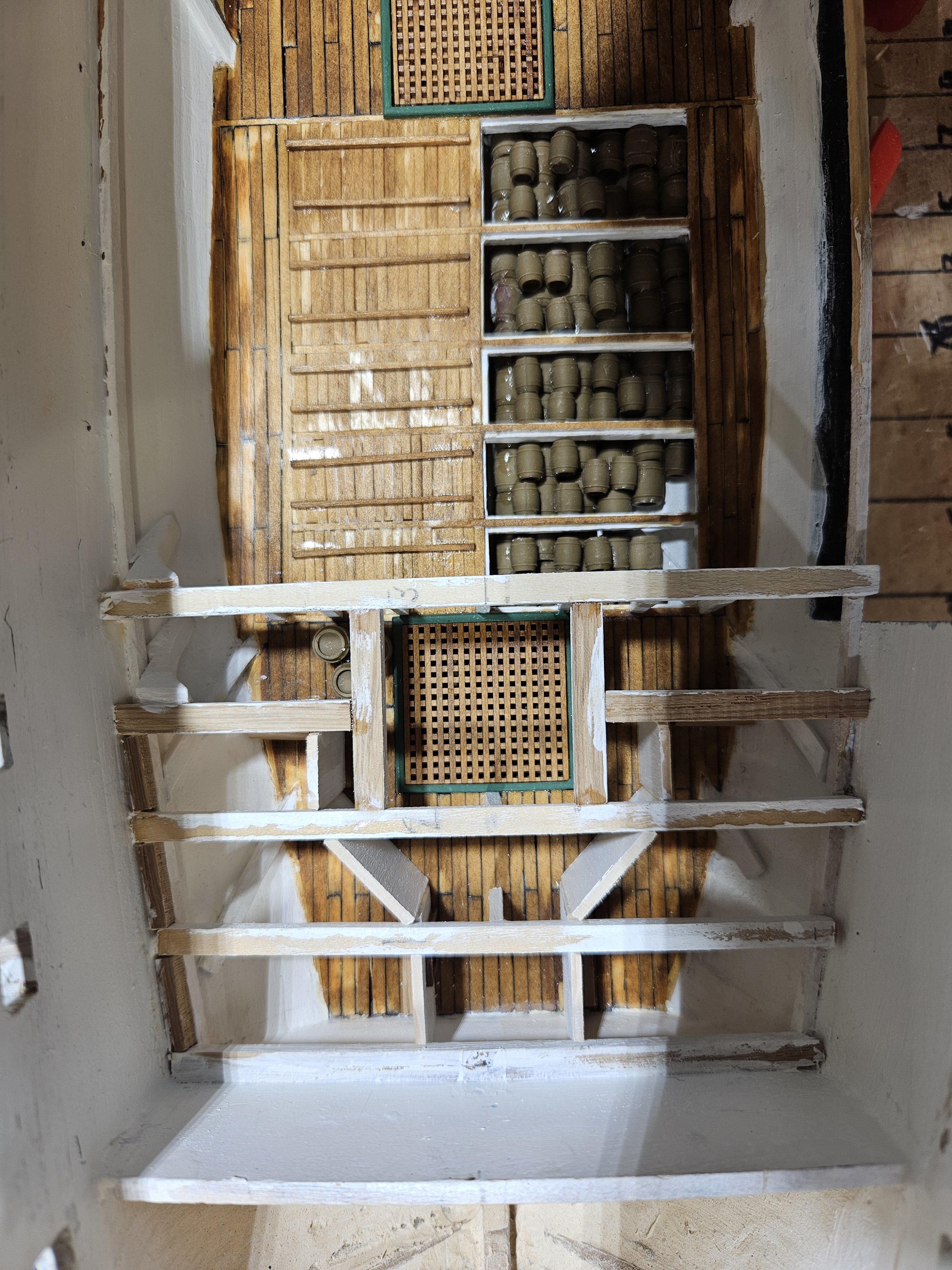
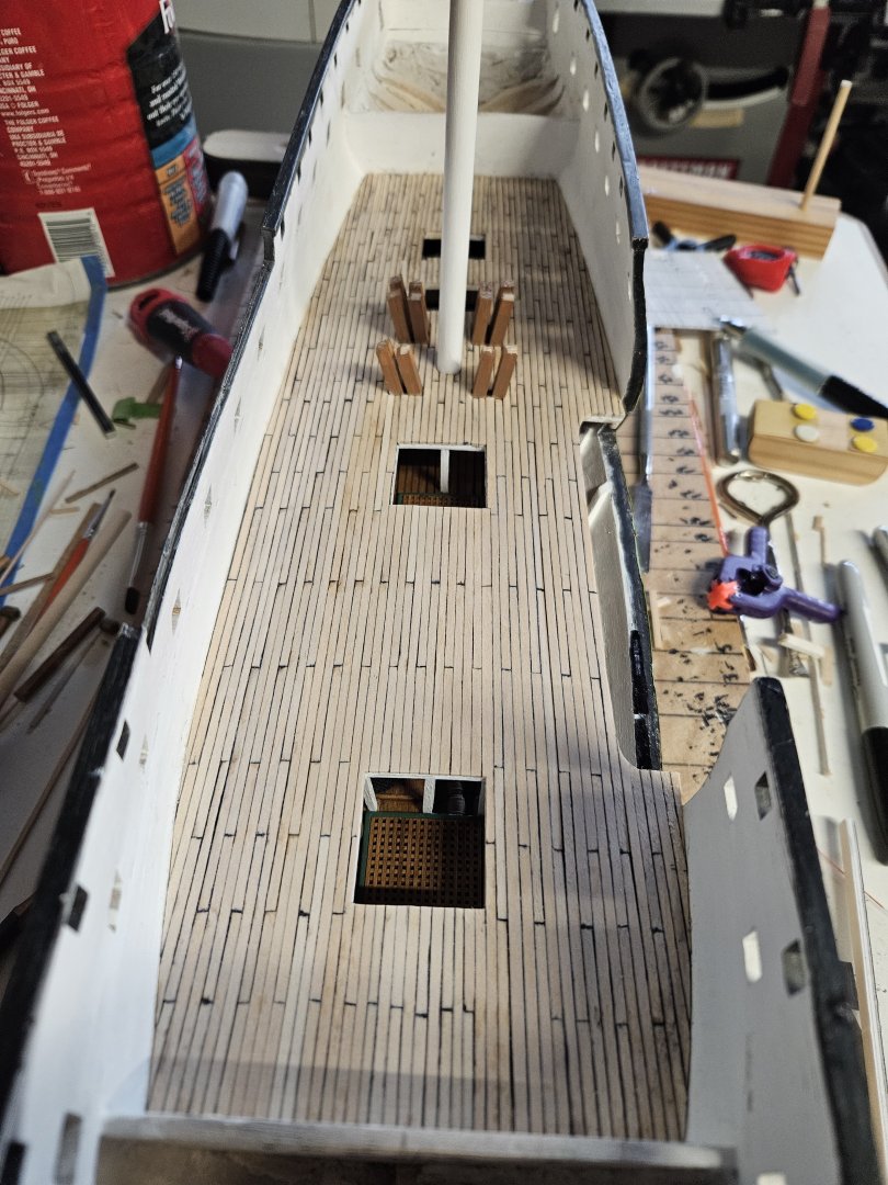
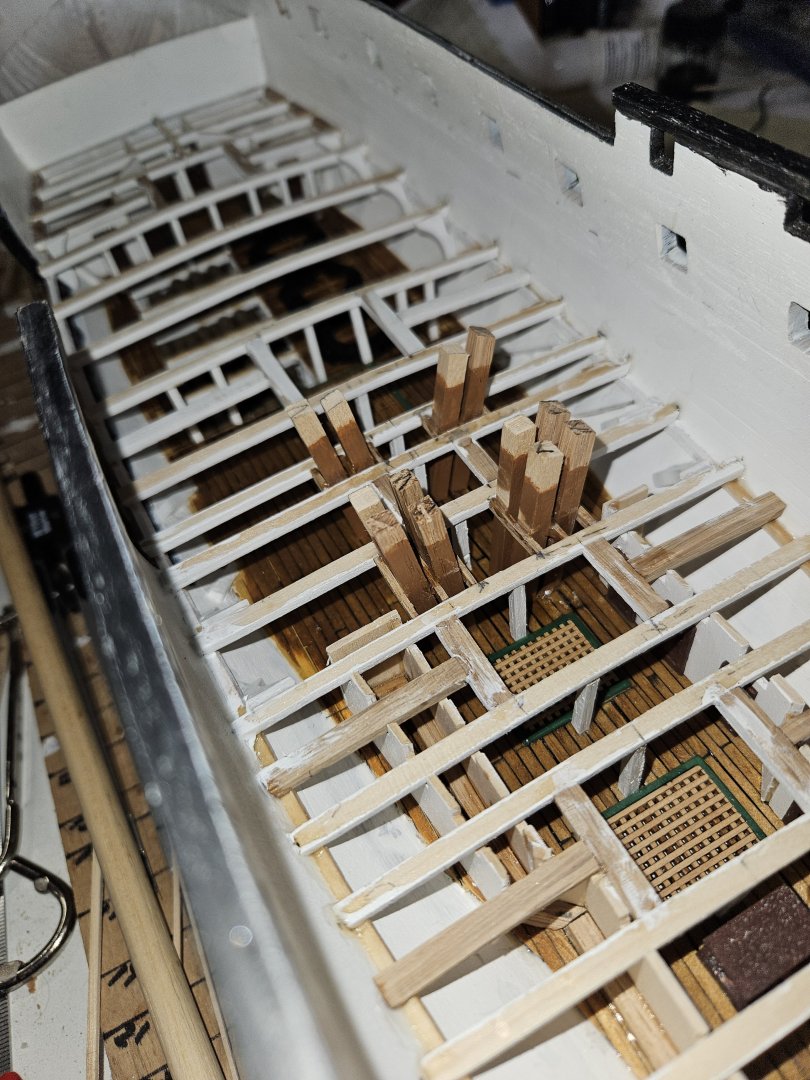
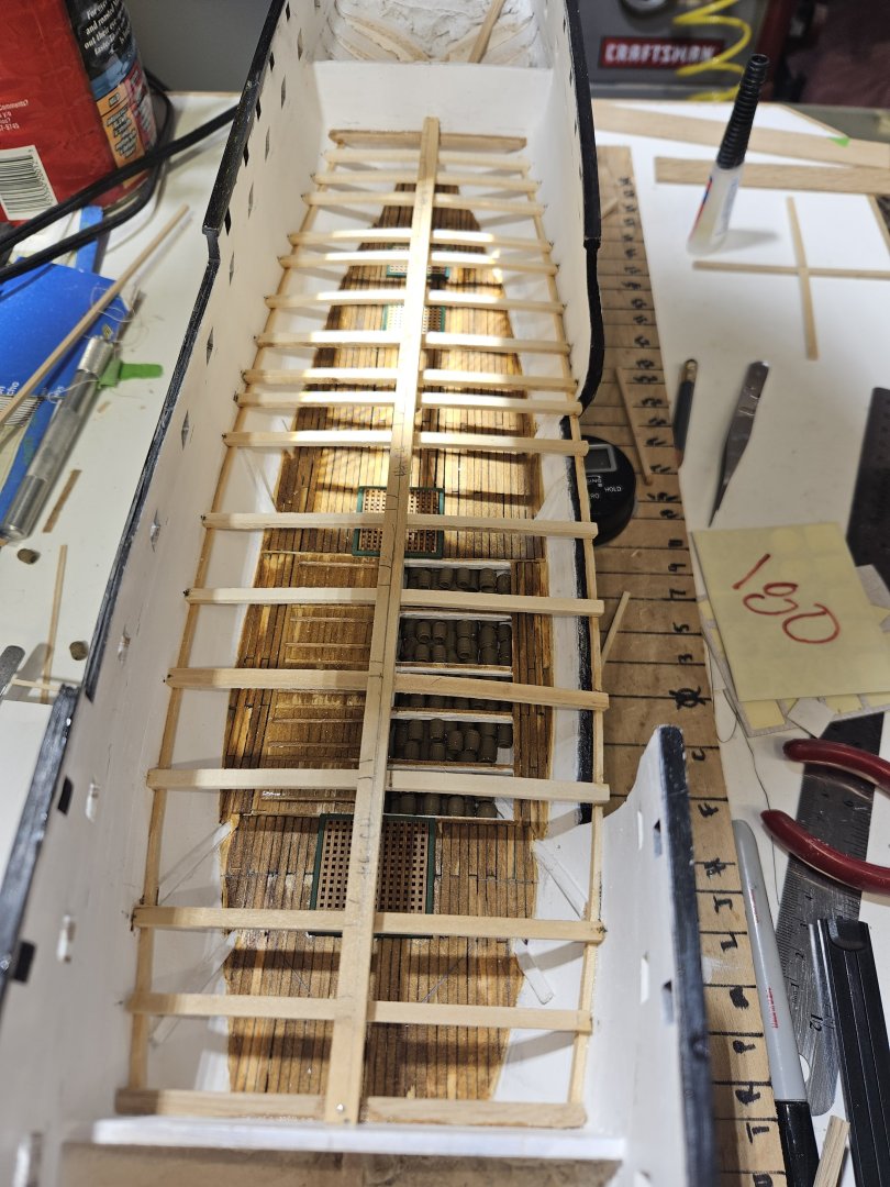
Gun Deck beams all installed and started installation of deck planks. Since the port side is open for viewing the lower decks, I felt it necessary to paint the Berth Deck overhead. Obviously, that would be quite the challenge after installation of the Gun Deck decking. So, I decided to paint one side of the sheet of .03 inch bass wood white. After the paint dried, I was all prepared to start the decking. However, a thought hit me regarding the seams. In the lower decks (Orlop and Berth Deck) when I put the seam on the side and butt end of the plank, it would bleed into the plank a little. In the instructions it says to do only one side and end to avoid excessive seam thickness. So, I elected to then stain and apply polyurethane to the other side, the top of the planks. And this is the start of the Gun Deck deck planking.


-
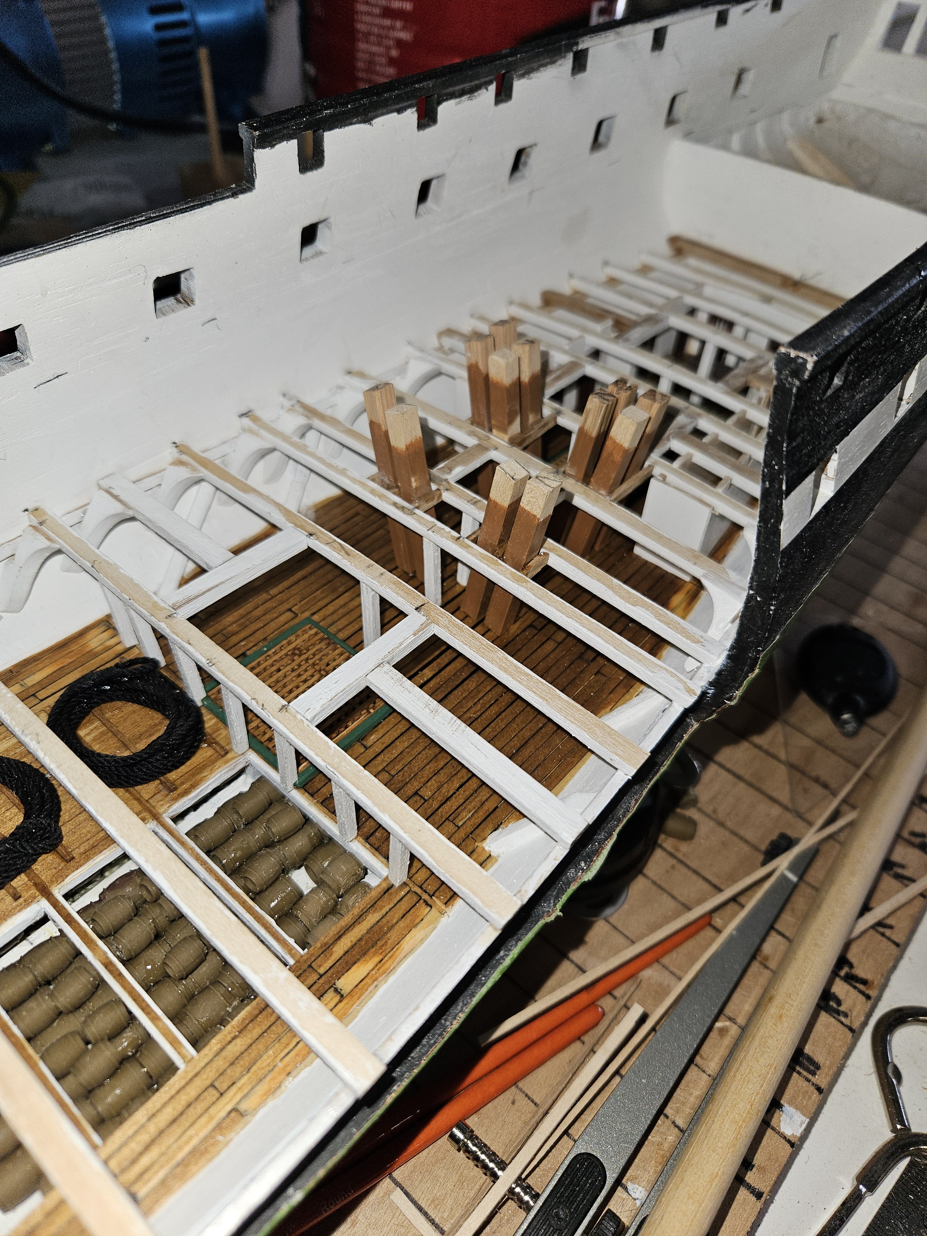
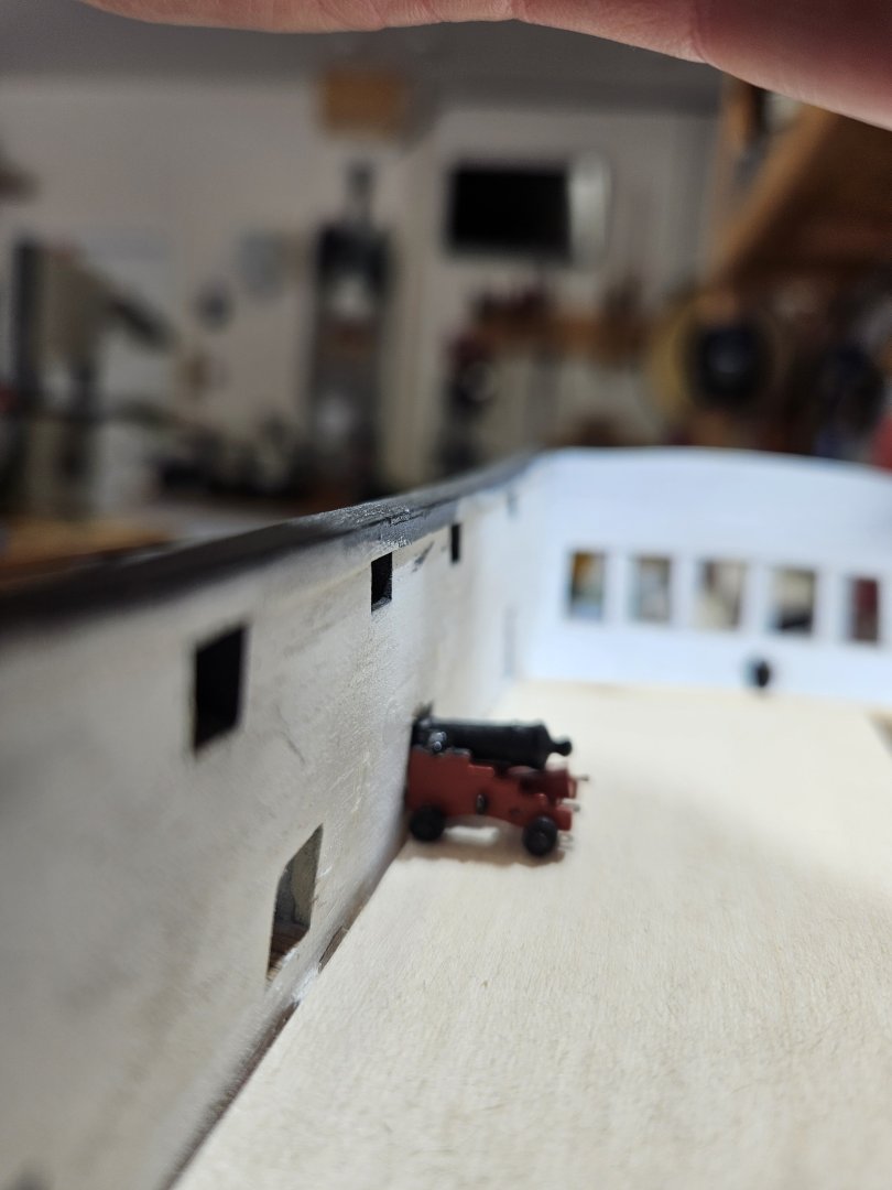
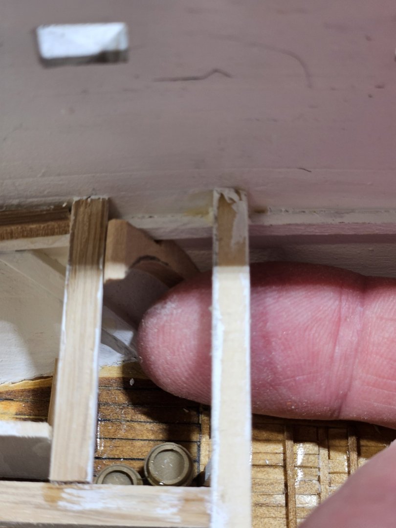
As I was making the stanchions for the Gun Deck, I wondered if the deck beams are at the correct height - meaning when I lay the decking (.03") and then the cannon would be centered in the gun port. Well, looks pretty good.

-
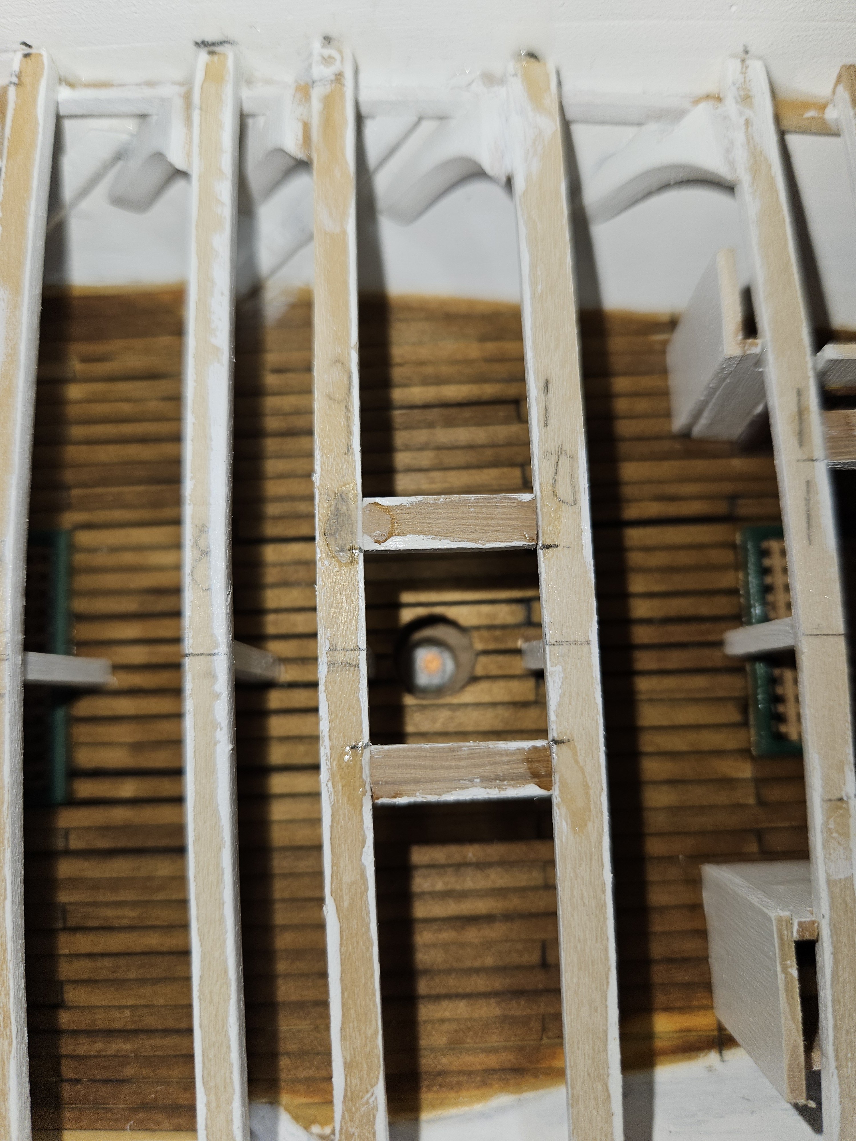
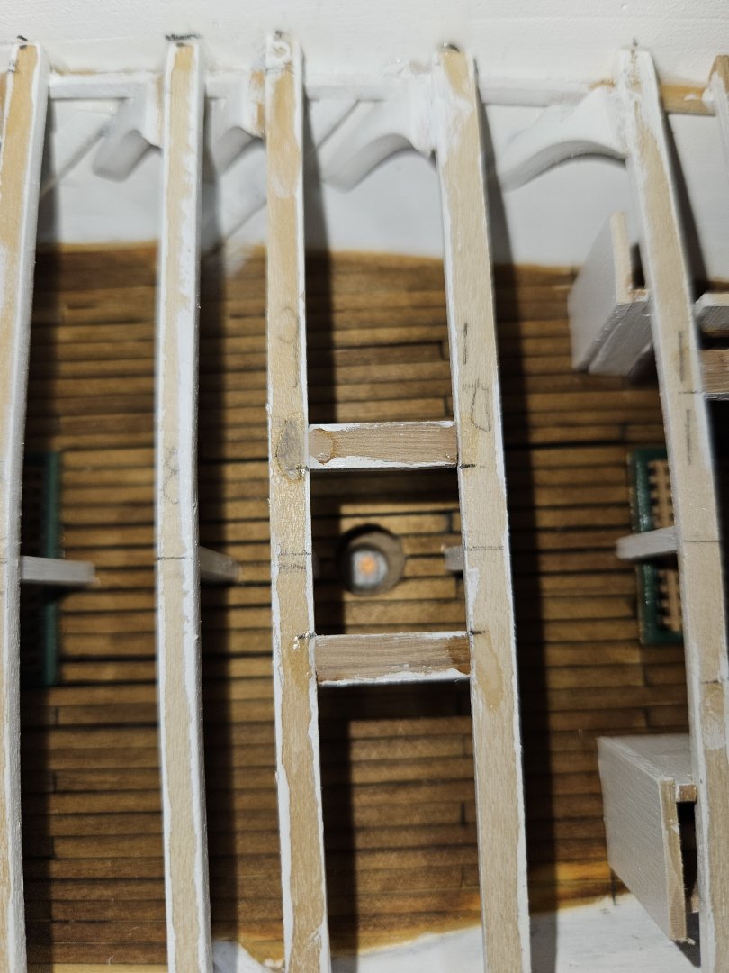
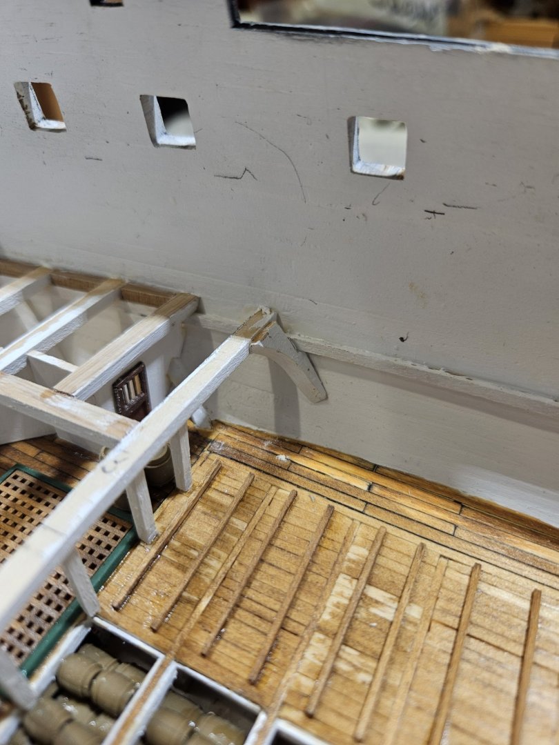
So, I asked Google AI and it came back with a no. The hatch railings, or safety railings, were not installed on the ship in 1812. When the ladder was not in use, the grating was put in place to prevent accidents.
-
Have a question for the group. Are there railings at the top of the hatches in 1812? In the kit there is a drawing of two railing types. Looking at the pictures, I cannot find one which has railings at the hatch openings. In Marquardt's book, I could not find railings either.
-
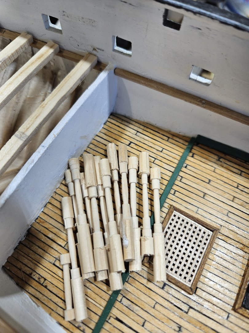
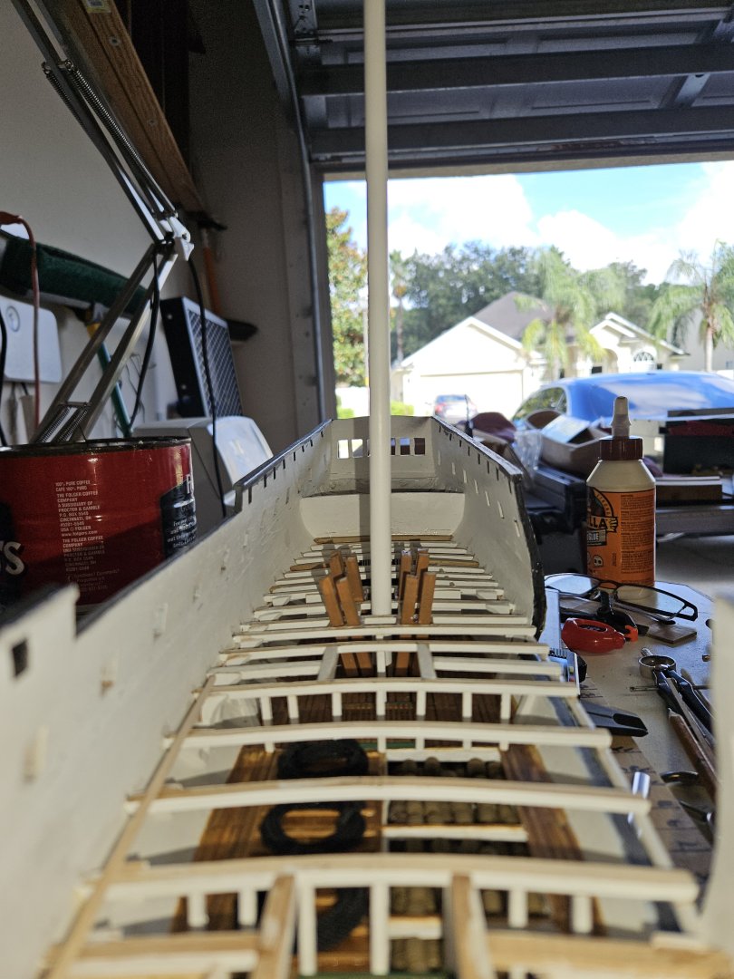
The Gun Deck beams aft of the bulkhead on the Berth Deck are installed. At this point, before installing any more beams, I have to lathe about 53 stanchions. I did look to purchase them, but could not find any (honestly, really did not look too hard). This justified the purchase of a lathe 🙂
-
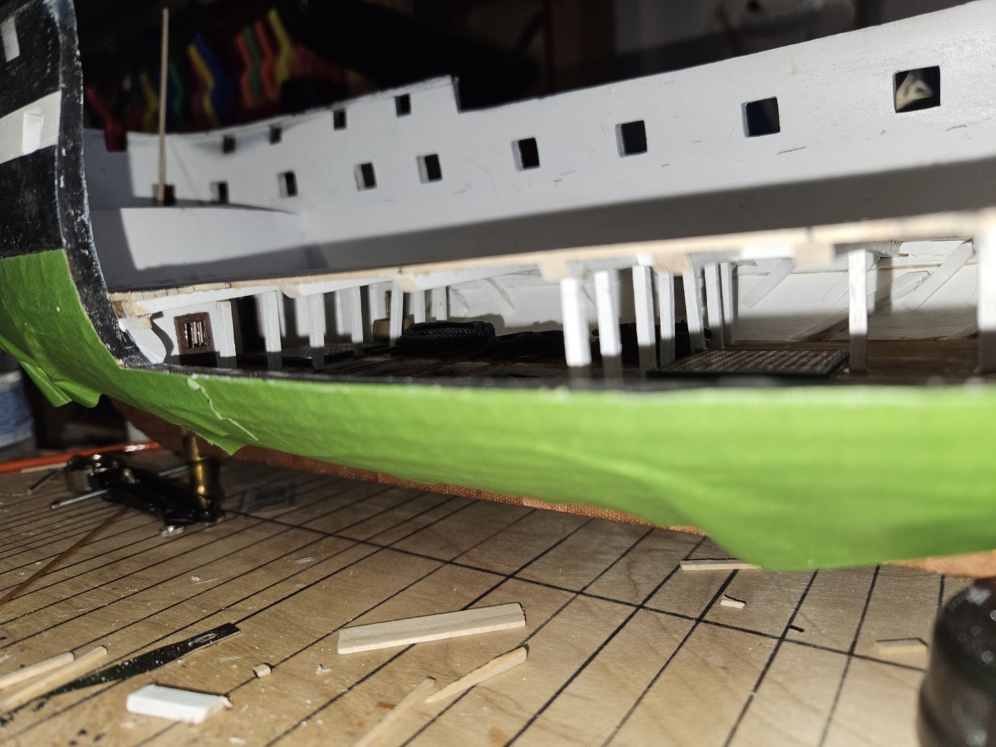
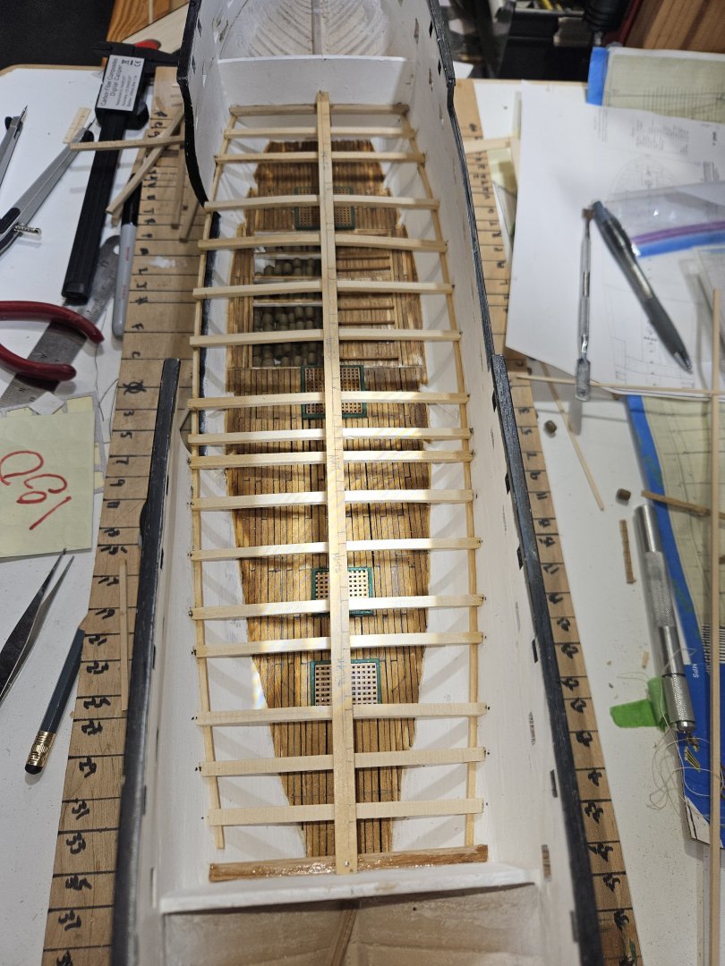
The decking is complete for the Berth Deck. I have started on the Gun Deck. My intention is to start installing the Gun Deck beams from Aft to Forward. Once I get to the green false bulkhead base, I will then have to install the knees with each beam. This is a lot more complex than the knees for the berth deck beams. Also, with the deck beams being about 6' apart, it would be near impossible to install the knees and if it was, they would not come out to my expectations.

-
Correcting myself. Not gunwale, but the waterway are (for the most part) in.

-
The Main Hatch is complete. On to the after hatches and then the gunwales. Once those are complete, will commence with the deck beams for the Gun Deck.

-
Forward Hatch on the Berth Deck complete.

-
Berth Deck decking stained and varnished. Started on the hatch coamings. Unlike the hatch coamings on the Orlop deck, I decided to form them inside the opening. It is going well, but in retrospect, I probably should have stained them prior to installation. LIve and learn.... Cheers, Brian


-
The Berth Deck decking is installed (still need to stain and varnish). For the port side opening, once I planked to just beyond the cable tier stanchions. Once the glue dried, I cut away the remaining beams and stringer. This opened up the viewing of the Orlop Deck. Next steps are to stain and varnish the deck. After that, move onto the hatch coamings and gratings, then install the ladders to the Orlop deck.

-
Started the decking. Using wood glue instead of superglue. Found that since superglue cured so fast, I could not get the plank tightly against the others thus leaving gaps between them. And, I admit, I am not the neatest when it comes to superglue. I have to sand my finger tips at the end of the day to get the glue off. With the wood glue, soap and water takes care of it. If you look closely, on the port side I made marks where I intend to stop the decking so the Orlop deck can be better seen from the side.

-
And the Main Lower Mast is stepped. Time to start on decking the Berthing Deck.
-
I feel the Orlop Deck is complete. Here are the views from overhead, looking forward and aft. The last pieces to put in were the up and down comers for the bilge pumps. That took a little research as the current CONSTITUTION has pipes. I found that they are square made from wood. This is so after battle, they could be easily repaired and put into use. Next step is to step the Main Mast, but first it would not be appropriate to step the mast without placing the good luck coin at the base. Since a normal coin would not fit, using a leather hole punch, I cut a piece of copper as substitute. Cheers, Brian After stepping the mast, it will be laying the decking for the Berthing Deck.


-
Thank you all for the recommendations and links. I did review them and analyzed the effort it would take to "adjust" the figurine to fit and have action, and it is too much. I would be working on the model until the end of time if I were to do what I feel is appropriate with regards to adding figurines. I am going to keep adding other items. Like in the cockpit, the surgeons table is setup with two casks for...well, limbs, etc. In the forward section of the Orlop, I intend to set up what it would be like for the carpenter. Also, there are a couple of casks by the main hatch ready to be hoisted up to the galley on the gundeck. Thanks again.
-
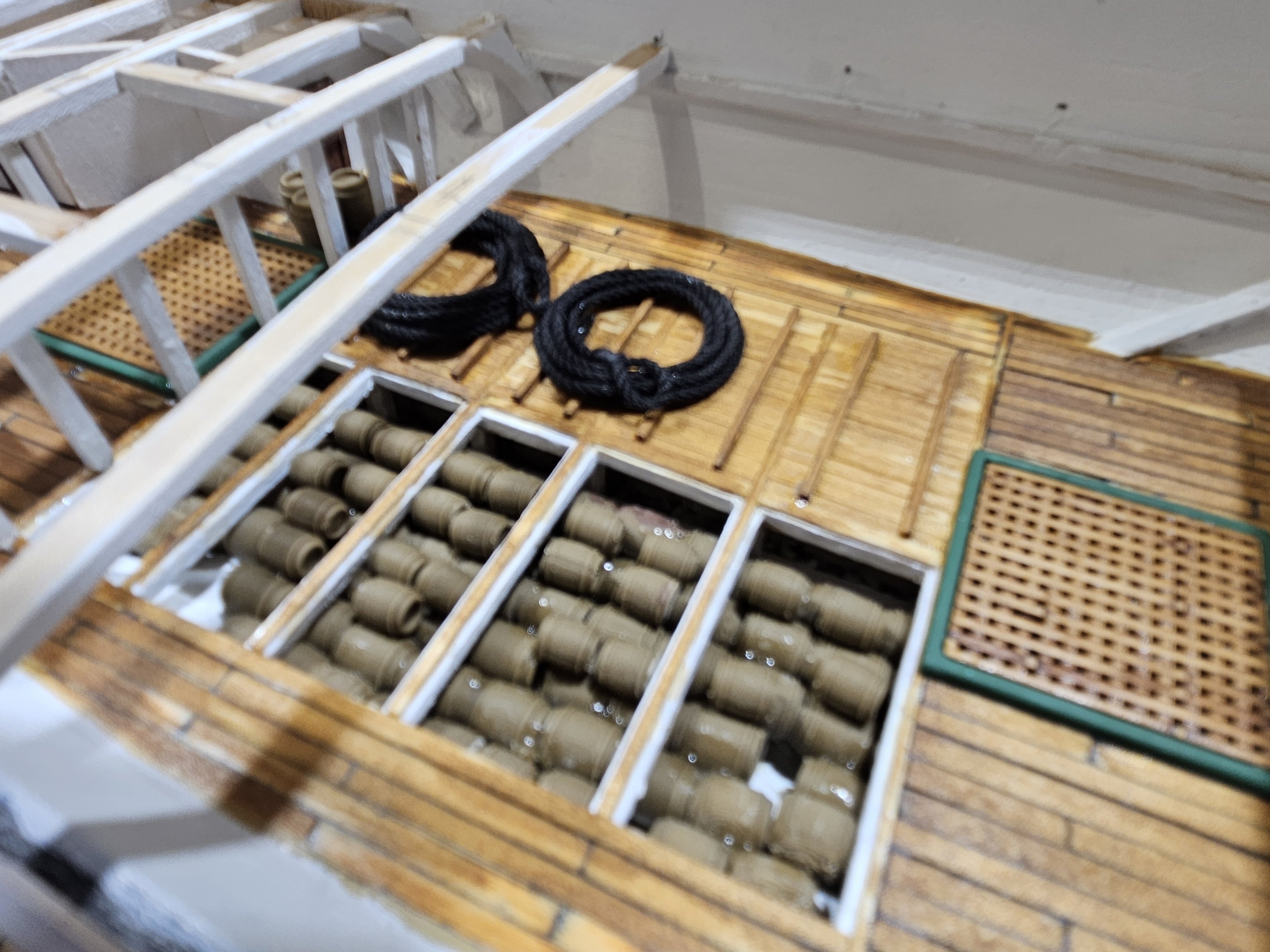
I have come to a decision on the figurines. Not doing it. First, could not find a good quantity of figurines that have some action. For the most part, they are just standing there. Second, could not find any at 1:96 that are US 1812 Sailors. And, felt I could not alter those that I did have into that era. So, instead, I will place those objects that give the observer the opportunity to place themselves in the action. On the Orlop deck I place a table and a couple of small casks in the Cockpit as if the Doctor were back there working on a Sailor (probably amputation). Up forward of the Fwd Hatch, I have placed a couple of larger Casks as if they are being readied to hoist up to the Galley. Amidships, on the Cable Tier, I have coiled line that would be the size used for the Anchor line. I still have to put something (have not researched deep yet) that has the Carpenter working on something forward. Now, will the observer be able to see these once I am finished? I do not know. But, I would rather have them there and not be able to see them than have nothing and be able to see a blank, dead space. Cheers.


-
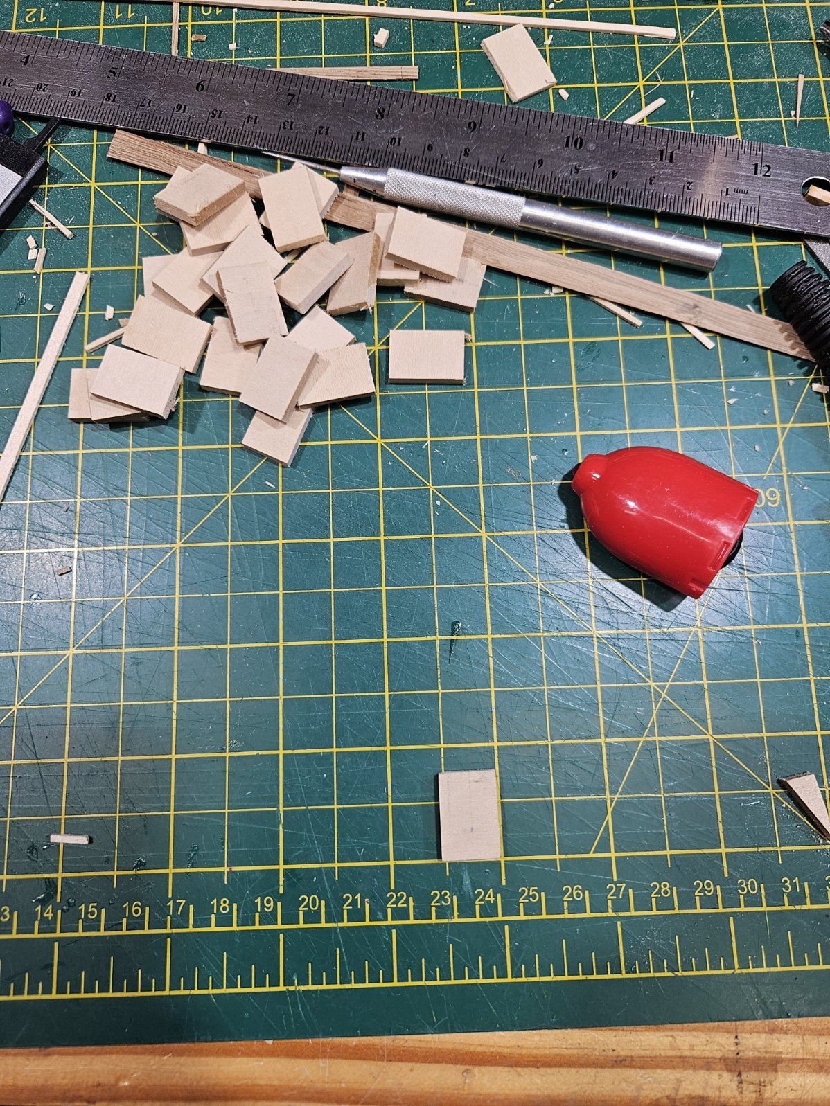
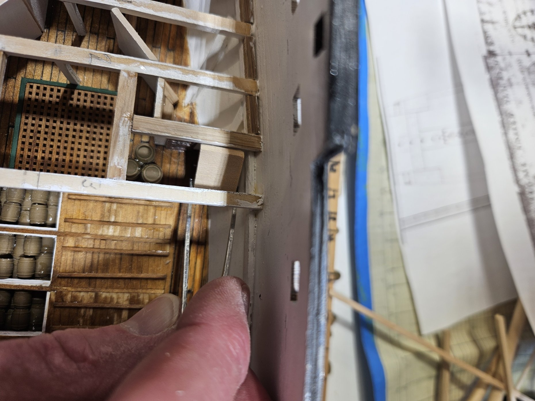
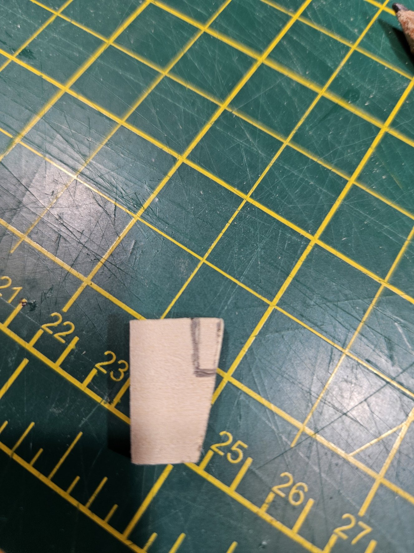
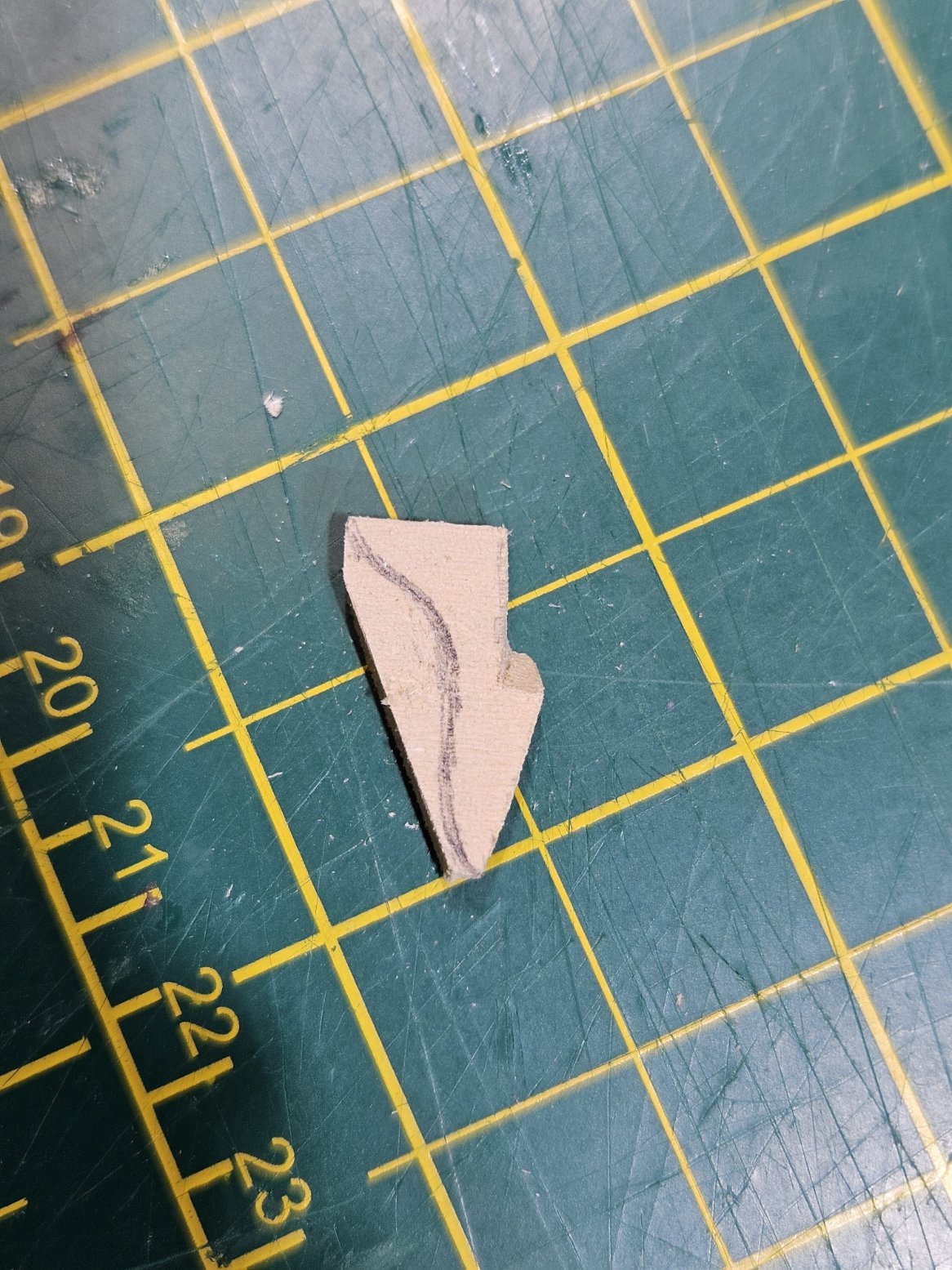
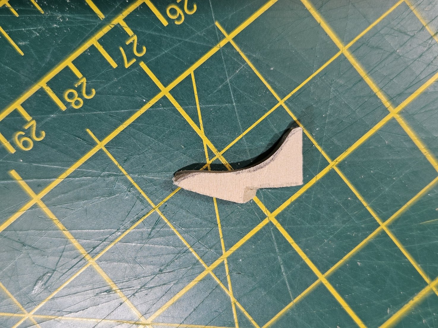
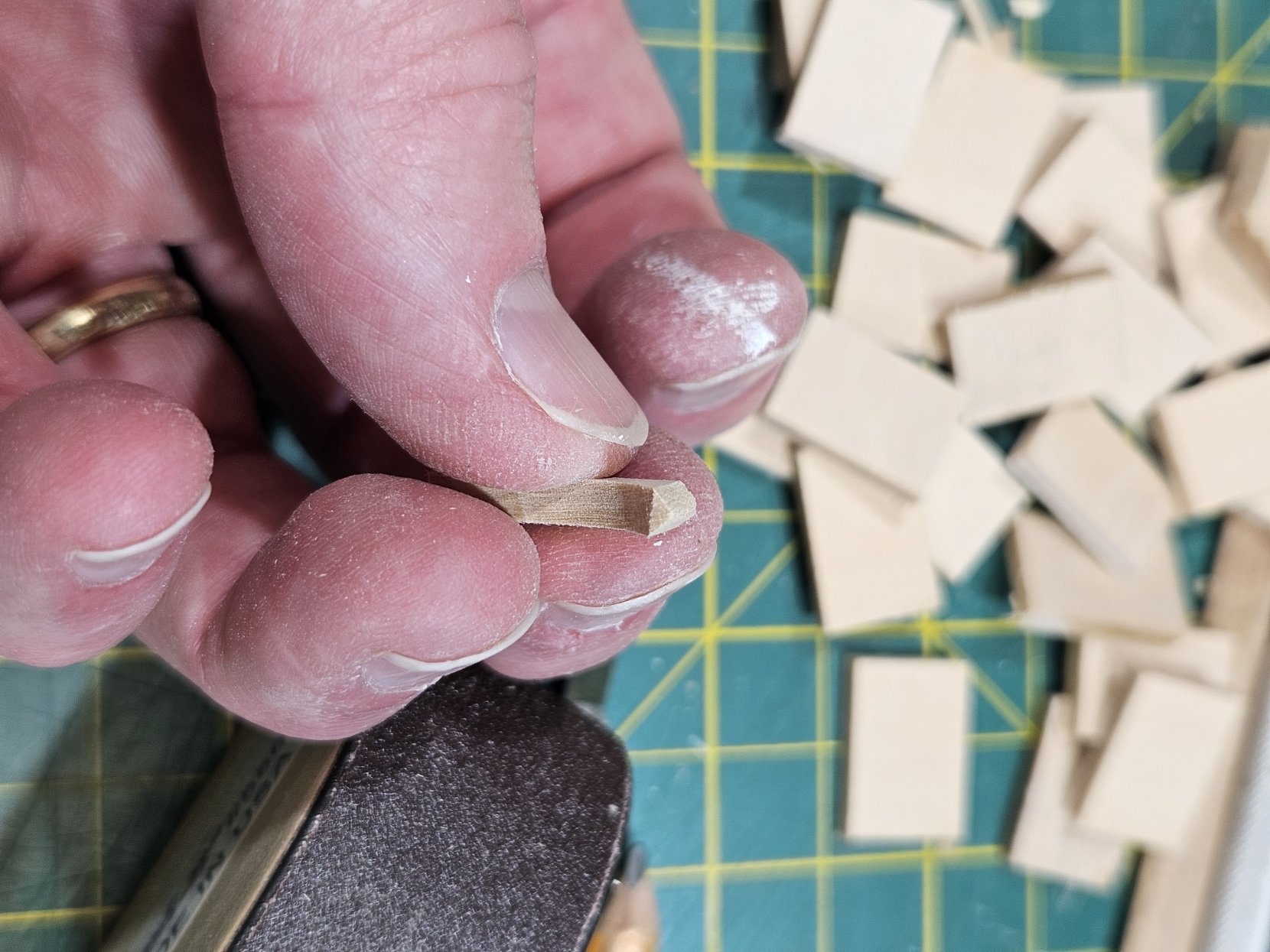
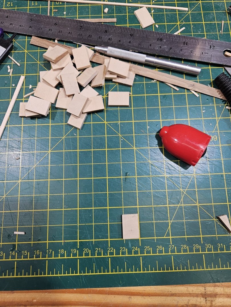
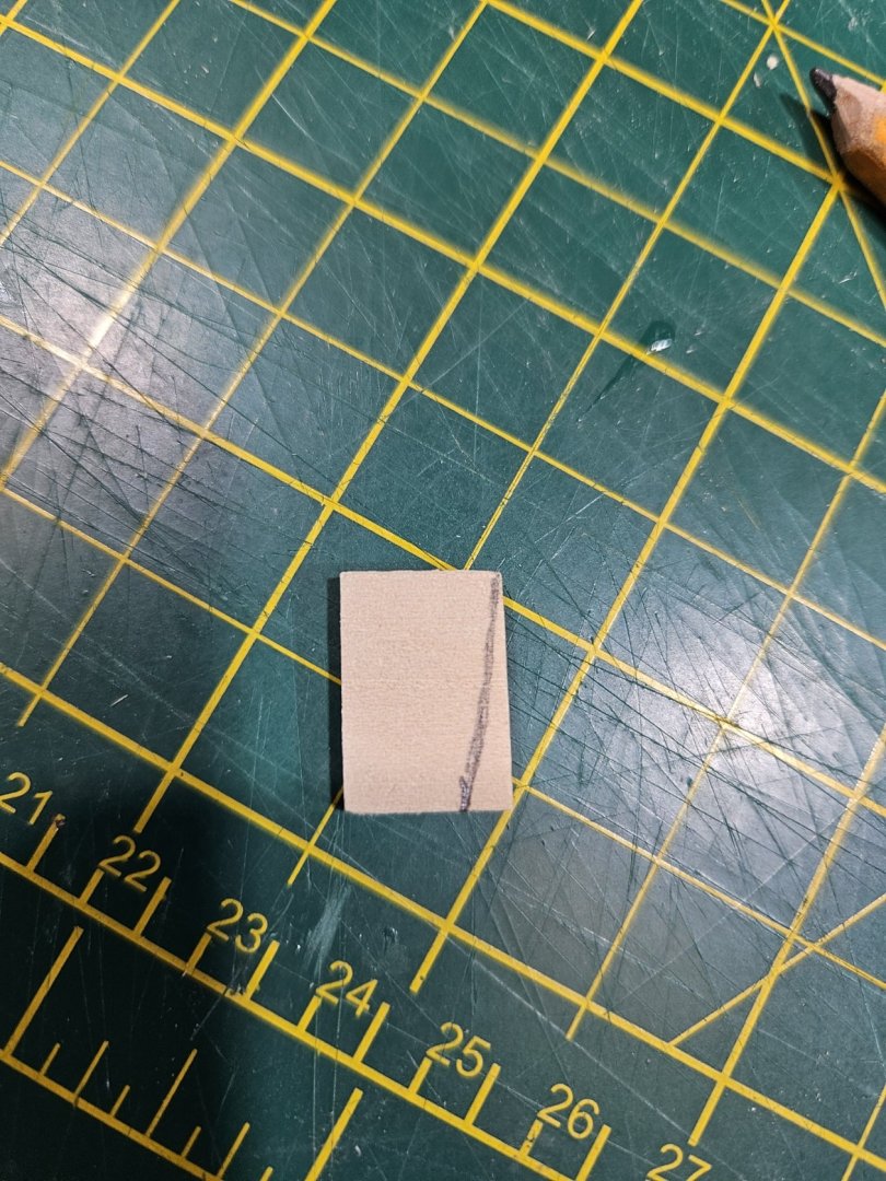
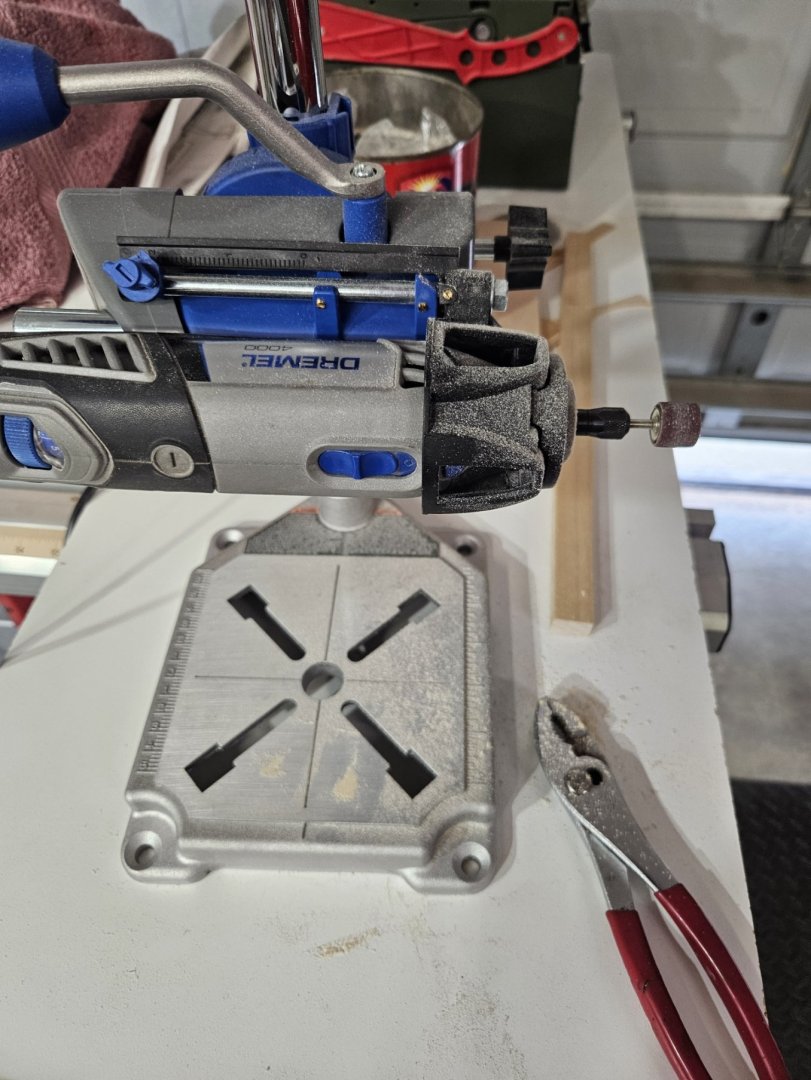
Now I am at the point where I was dreading the most. Making the knees and installing them. I have seen them in real life, seen them in pictures, and seen them in drawings...I just could not see making them with any semblance of accuracy. So, I decided to start at a basic level, just the length and height. They are 4' x 6'. That is what I started with, 1/2" x 3/4" x 3/16" pieces of stock. Here is the start: With this, I placed it against the hull at the 45 degree angle to find how much in do I need to cut given the curvature of the interior hull. Here is how I got that dimension With the square in place, I put a tick mark on the beam. Then took the stock piece, placed it atop the beam and transferred that tick mark onto the bottom of the stock piece. I then free-handed the curve from the top corner to the bottom tick mark as seen in the picture below. After cutting and doing a little sanding on the side against the hull, I then place the piece back into position to define the cutout for the stringer against the hull. After cutting out the notch and again, checking for fit, I then free hand drew the knee. And then cut the corner off in preparation for sanding down to the curve. Using the Dremel sander I ended up with this Then sanded the edge against the beam and the berthing deck to fit into the corner And then the final fit test before painting and glueing in.


-
I have started on the Aft section of the Orlop deck (Cockpit, storage rooms, etc.). For this section, I will be sure to include the Carpenters' Walk. Still debating about figurines. I do have a batch coming in from Dean's Marine. The last batch came from a railroad model store and everyone looks like they are standing around waiting for a train (go figure...), no action to them. I did have another group which looked great around a gun, but the maker only makes like 12 figures which would lead to repetitiveness. This is a trial scene... Guess I just wait and see what Dean's Marine has for me....


-
Finished the compartments in the forward section of the Orlop Deck. A couple of mistakes that probably will not be noticeable. I neglected to leave space between the interior hull and the spaces, the Carpenter's Walk and the Cable Tier stanchions are off a little bit. There should not be one centerline. Other than those two, fairly pleased with how it came out. As for figurines, I have ordered some from Deans Marine. Do not know when they will get here, but for now, I have moved onto the aft section. 

-
All major beams for the Berthing Deck are fitted. I initially planned on keeping them in place as I installed the Orlop Deck bulkheads but quickly realized that would be too challenging. So I place a small mark on each side to mark the location of the beam, numbered each beam, 1 being the most forward beam and removed them all, including the centerline stringer (which was temporary anyway). Prior to removing all beams. After removal, I painted them for final installation. But before moving forward with re-installing the beams, I laid base board along the interior of the Orlop Deck bulkheads to glue the bulkheads to. This is the Aft portion of the Orlop Deck: And this is the forward portion of the Orlop Deck with the first beam reinstalled and the first bulkhead fitted. Prior to final installation of the bulkheads, they will be painted and doors installed. My plan is to work from the most forward part aft until the last bulkhead of the forward section is complete, then shift to the most aft bulkhead and work forward until that section is complete. Then I will determine if I want figurines or not (not having much success in that) and lay the cable in coils on the cable deck and place a spare anchor against the starboard hull.

-
I replace the stringer (?) from the post above to something more substantial and pinned it into the most forward and aft beams. In the below picture, you can see where I marked off each beam and the centerline. This aids in ensuring I get the beams spaced appropriately and centered side-to-side. The first three are in. Once all major beams are in, I will continue finishing up the Orlop deck. If you look on the decking for the Orlop deck you can see the pencil lines for the bulkheads. Cheers.

-
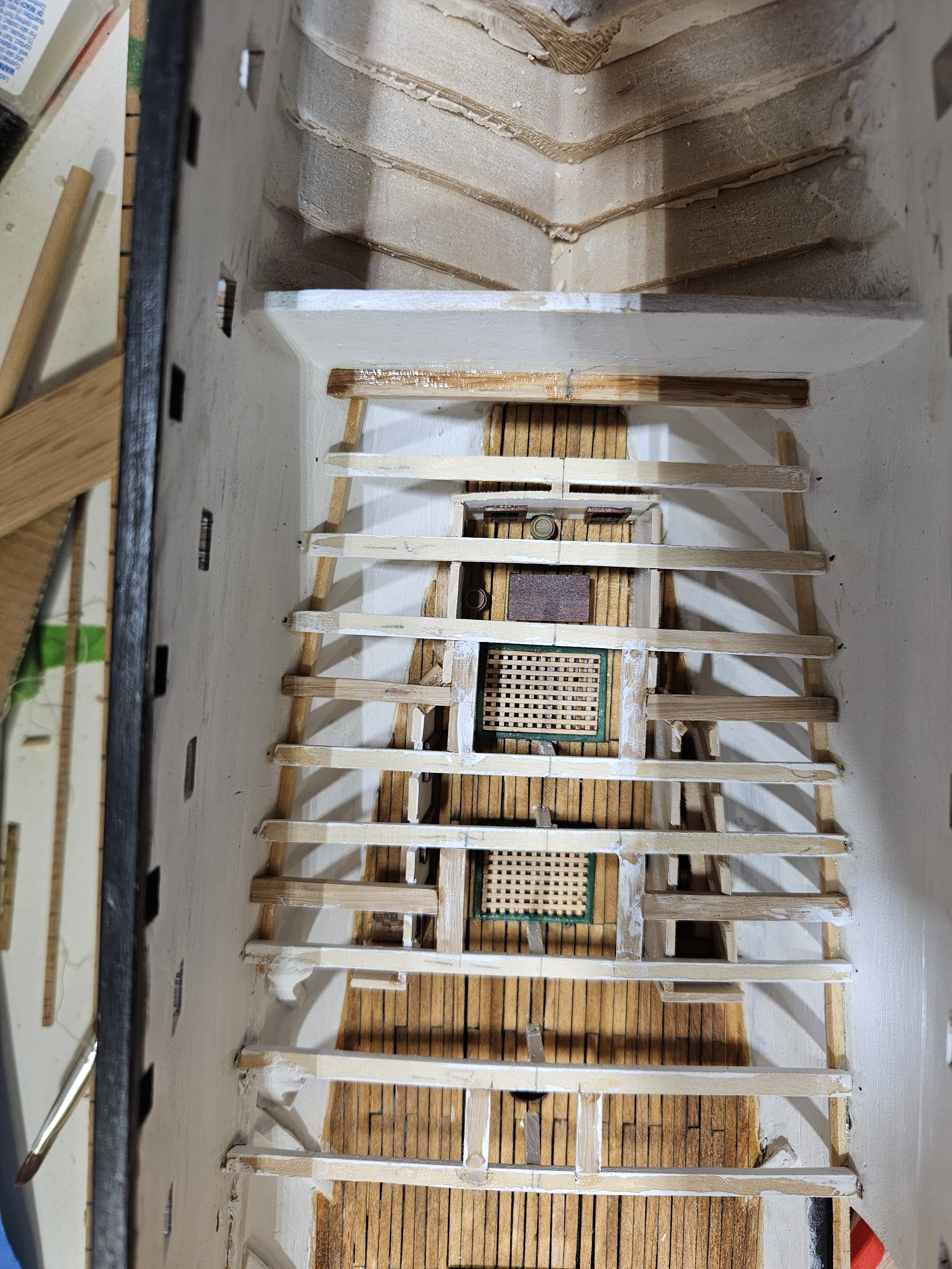
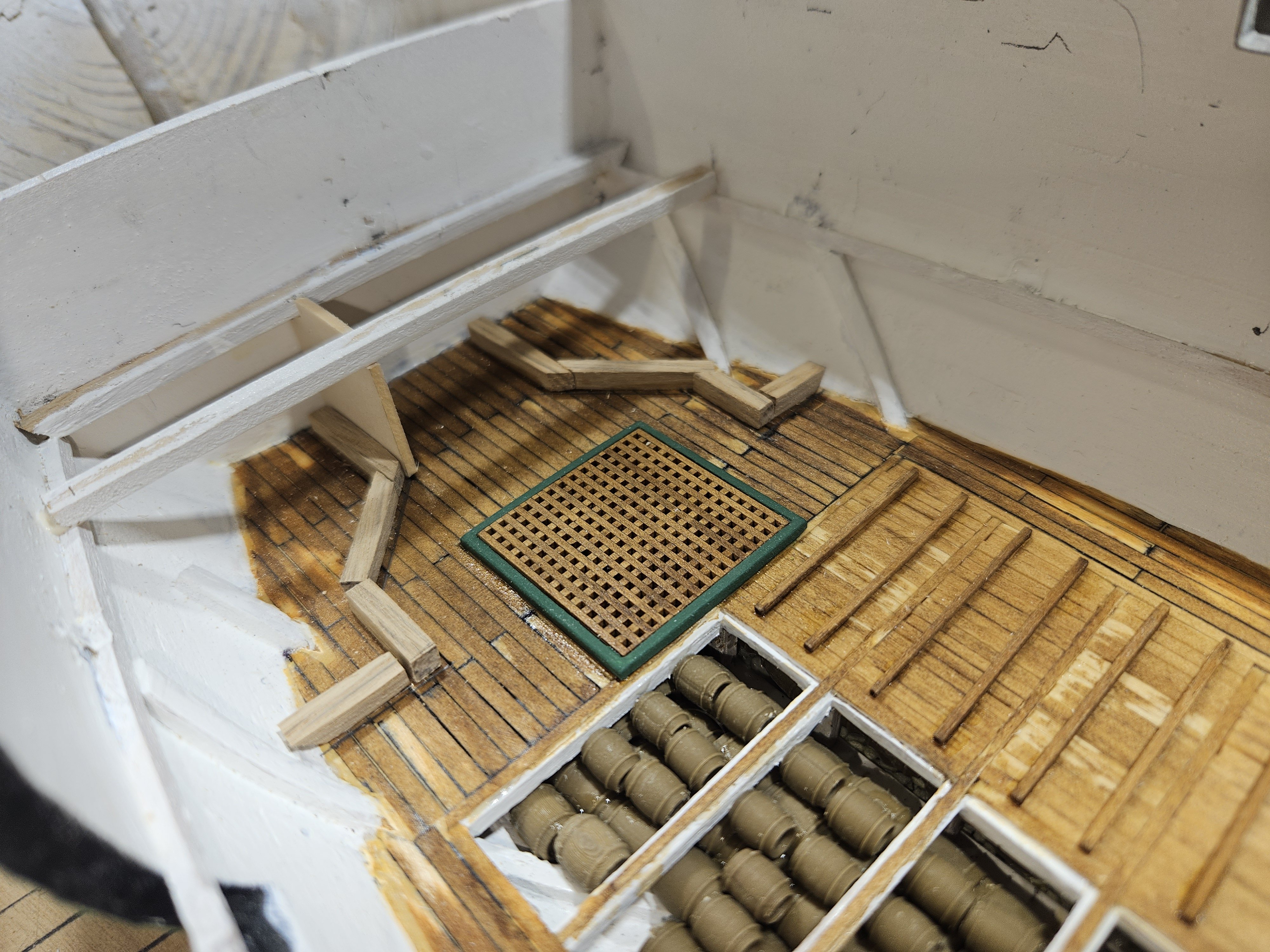
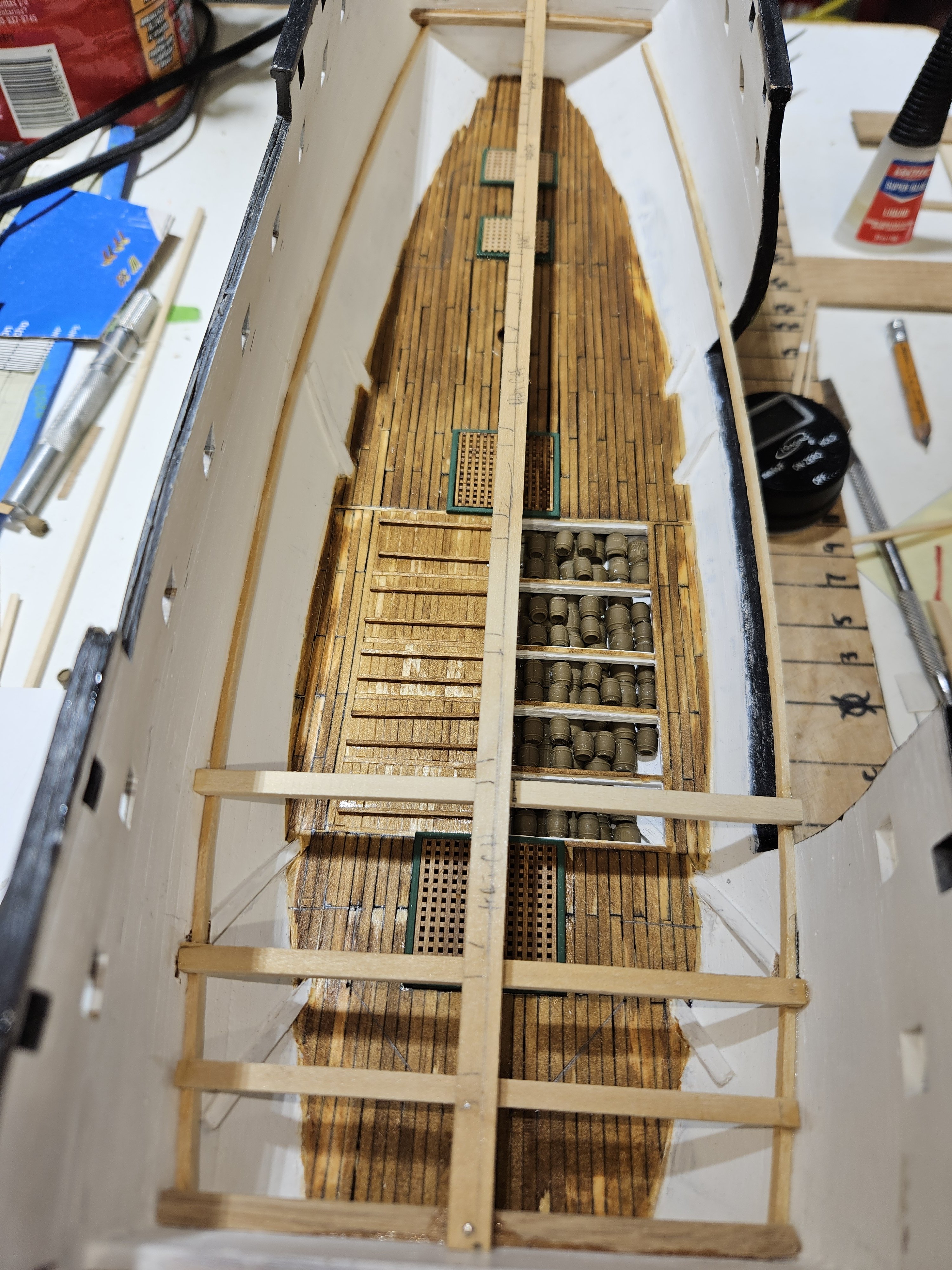
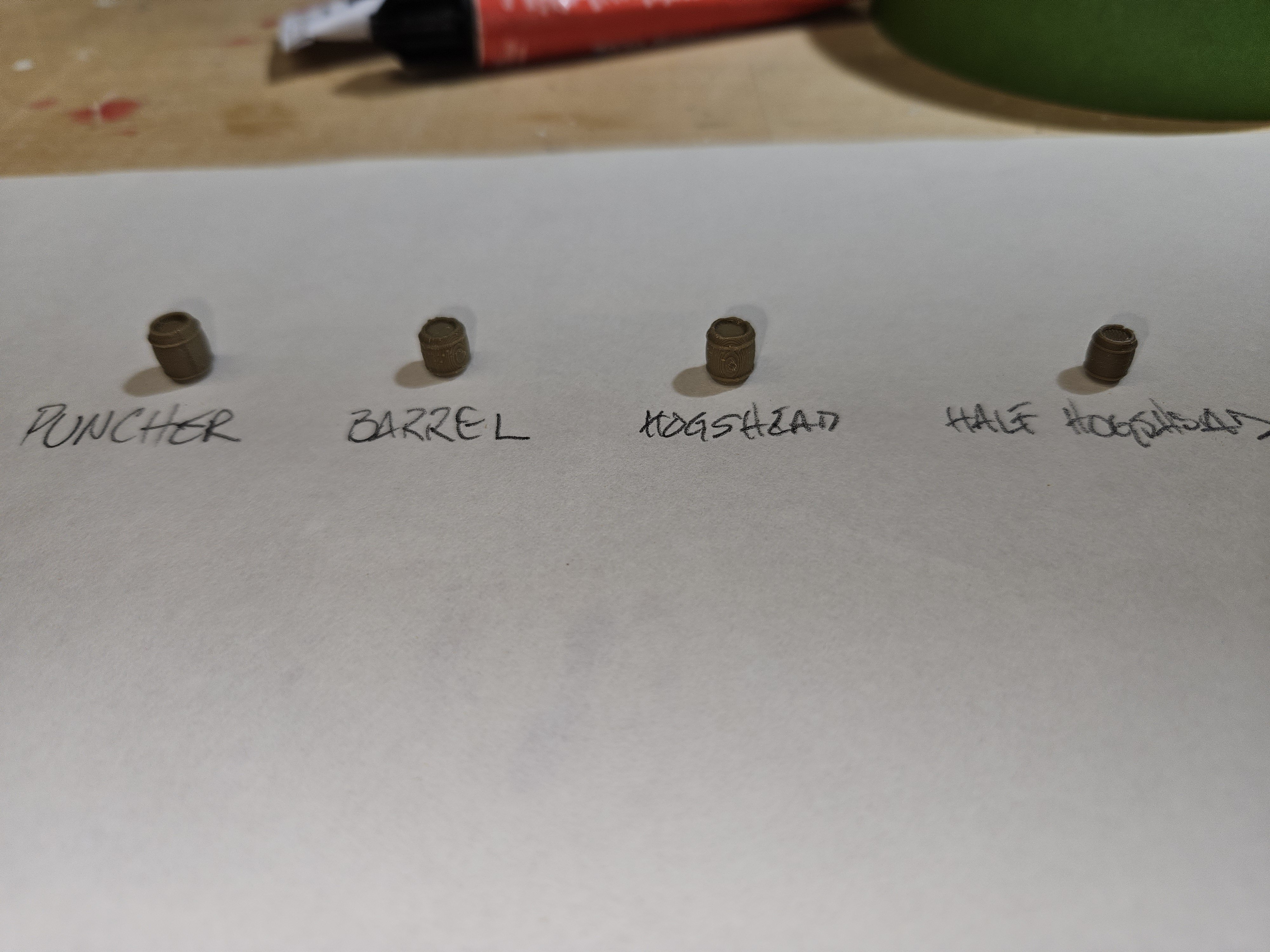
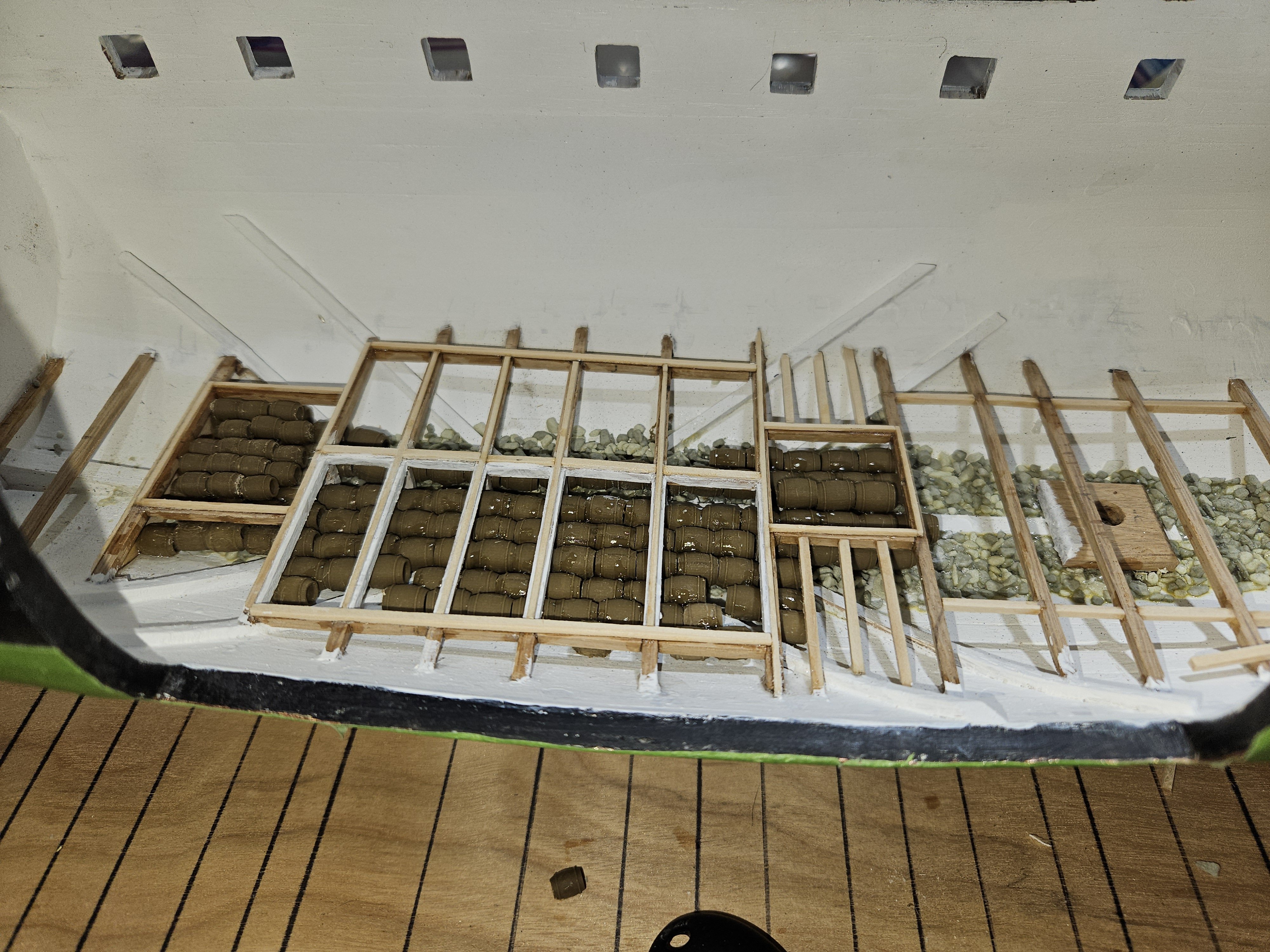
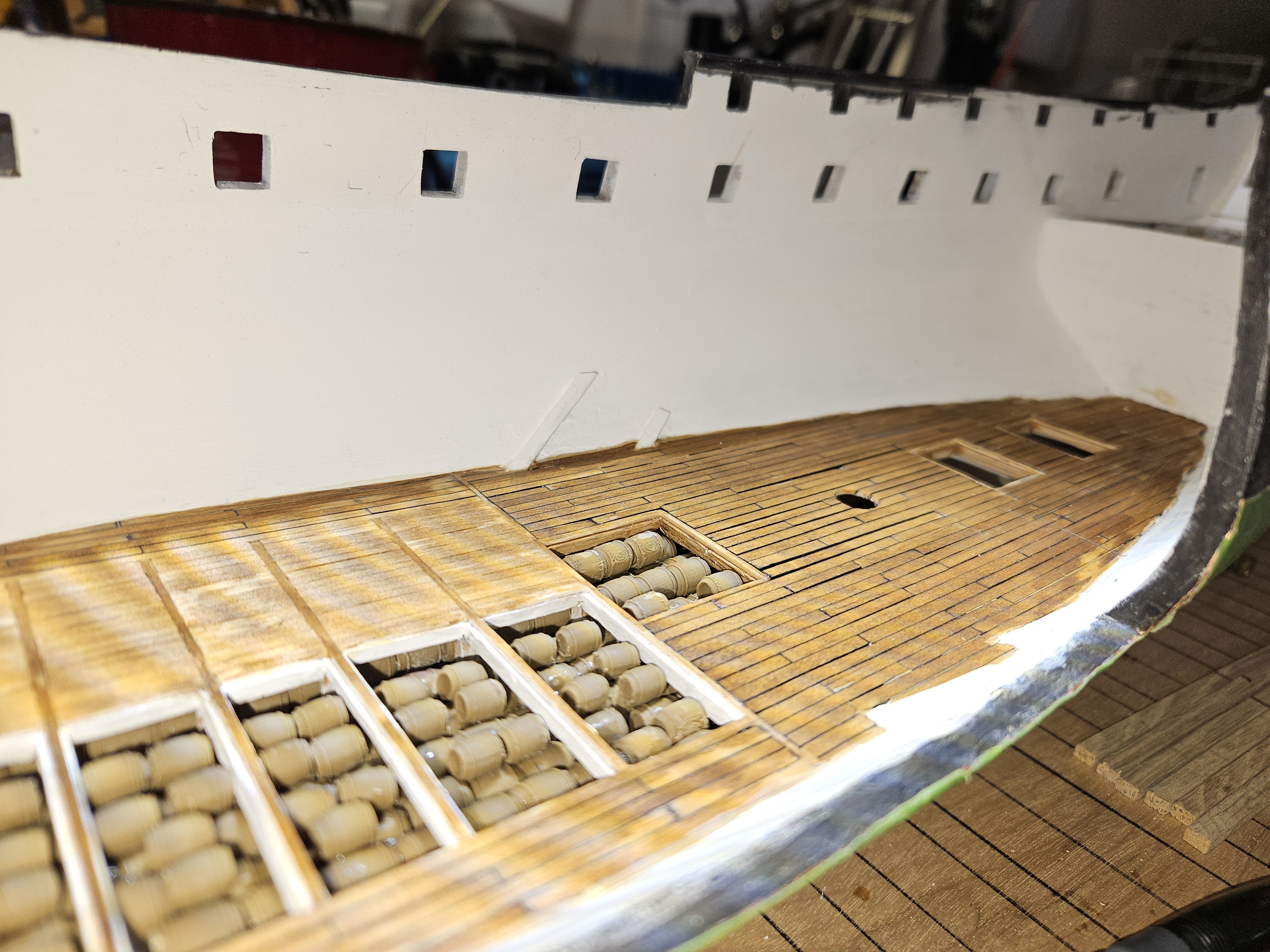
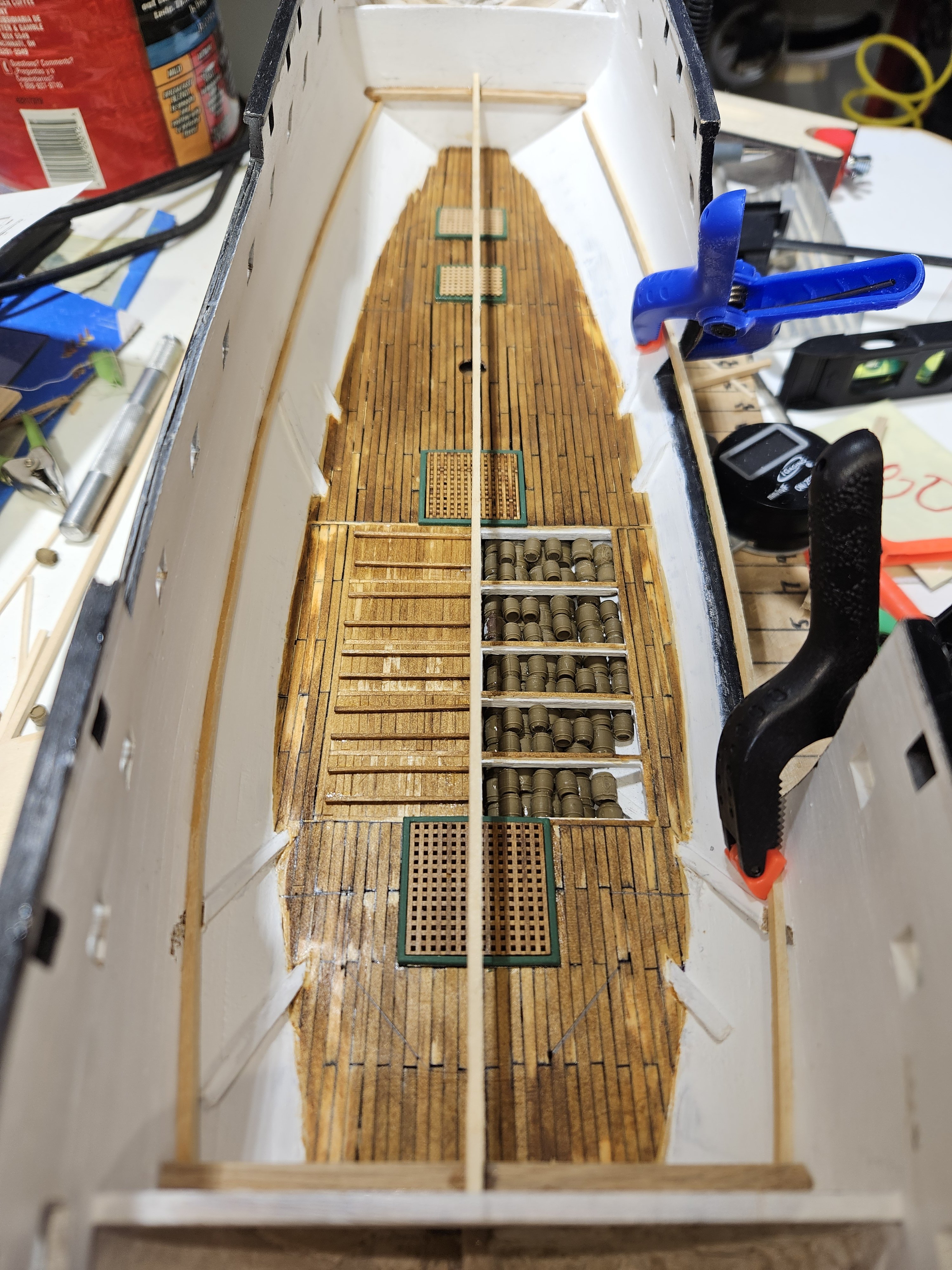
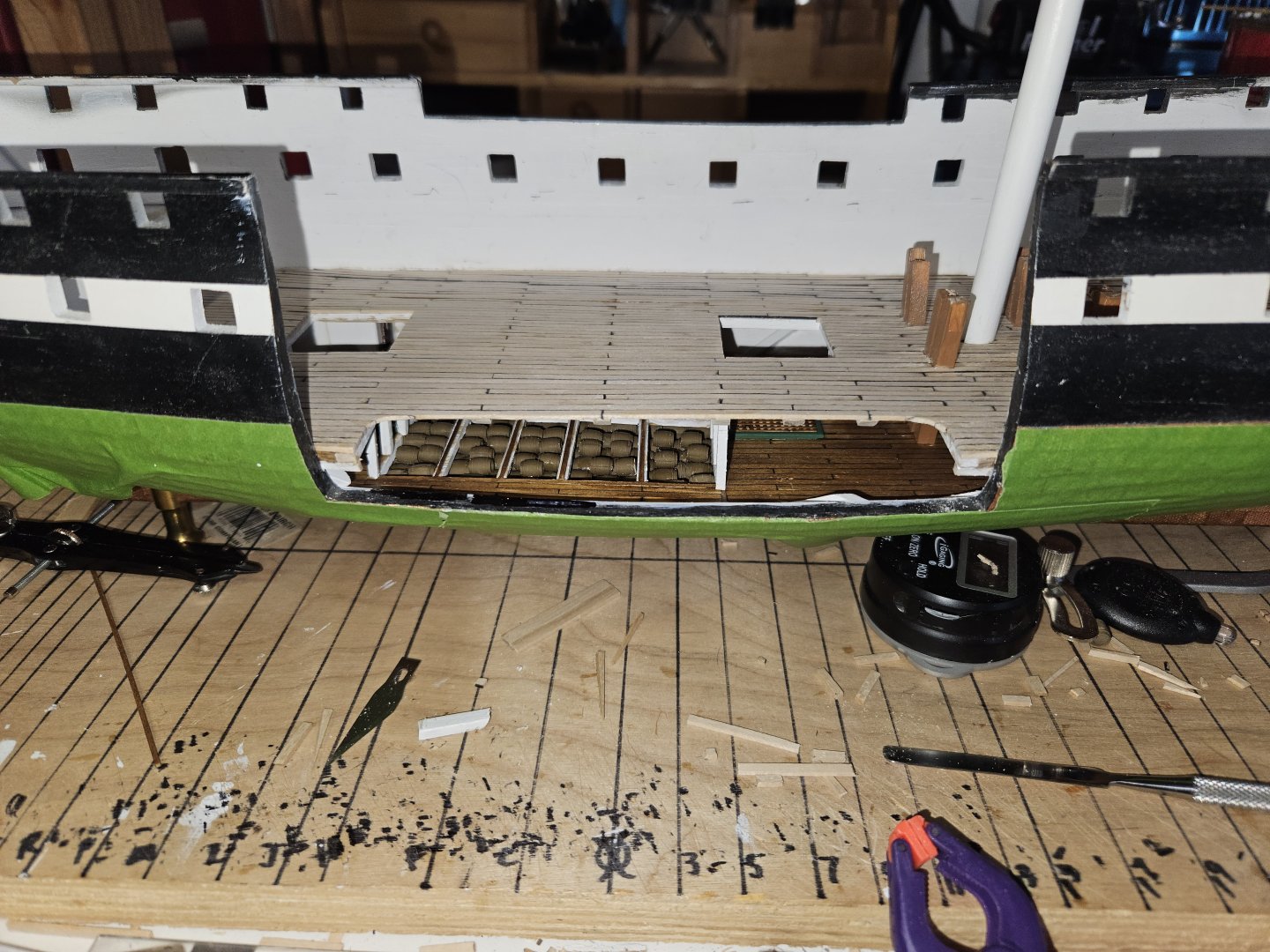
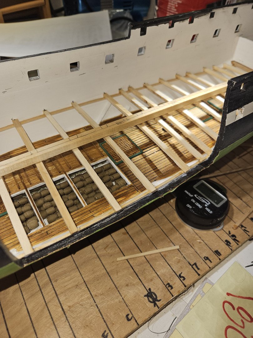
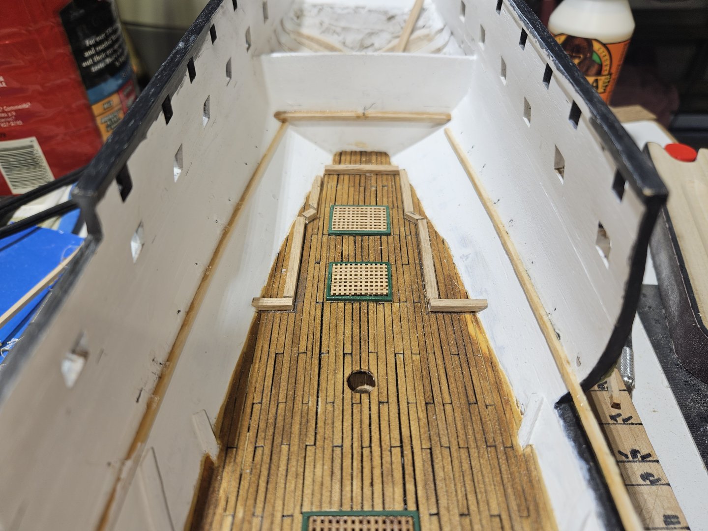
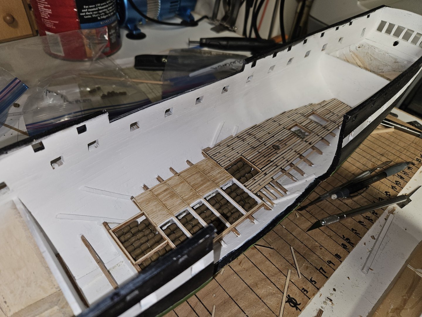
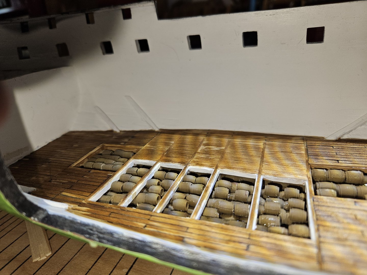
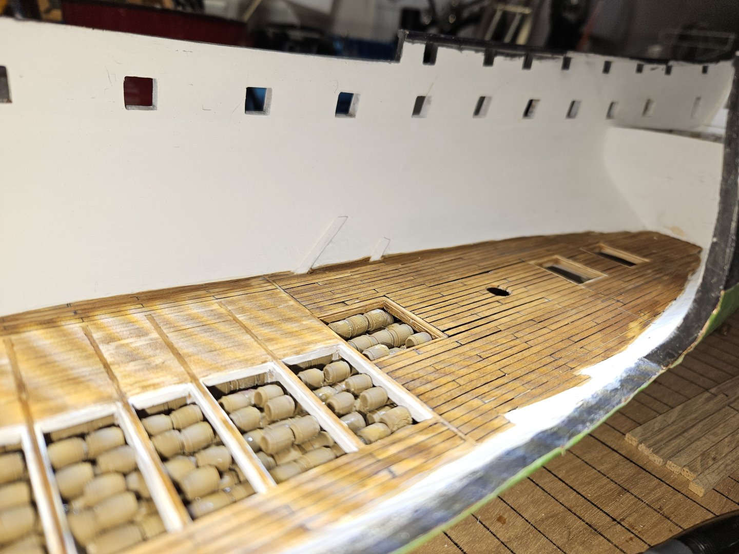
From the last pic to the current, I did make progress - just failed to document here. Using the method I described above (November 28th post), I was able to install all cross beams and hatches. Prior to laying the deck, I outfitted her with a full complement of stores. The casks are 3D printed (could not find the correct sizes) casks. Here is a picture of the different types. And with all beams and casks in place: Using .03in thick by .06in wide white pine, I commenced planking the Orlop deck. The black between the planks is permanent marker. The section amidships is the cable tier. I researched and researched how that was in 1812 and found nothing, or scarcely nothing. So, I suspect that stores were in the hold below the cable tier deck and those sections could be removed for access to the hold. I installed the cable tier deck on the starboard side and left the larboard side open to the hold. The small section against the hull is the carpenters walk, which will be planked as the rest of the deck. And this is the finished Orlop deck looking forward and aft: After completing the deck, the next step was to install the coamings and gratings for the hold access. Because the BJ kit does not include the parts for the Orlop (only Gun and Spar decks), I researched other model parts providers and found 1:72 scale gratings at drydockmodelsandparts.com. Their actual thickness is .03in, which comes to 3 inches at 1:96 scale. I really do not think anyone will be able to see a .01 difference. Here is the forward hold coaming and grating: After installing all coamings and gratings, I am at a decision point. Should I move onto the Berth deck framing, or continue with the Orlop deck knowing that what I install may have to be adjusted due to the Berth deck beams. I moved onto the Berth Deck beams and will install the finishing touches (figurines (still debating this one), bulkheads, doors, anchor cable, spare anchor, etc.). So, moving forward, I installed the aft and forward most beams. Using basically the same method for installing the Orlop beams, I placed a stringer (?) forward to aft to guide me in the installation. Here is where I am today: The cross beams will go on top of the stringers along the starboard and larboard sides and under the centerline stringer. Cheers, Brian


-
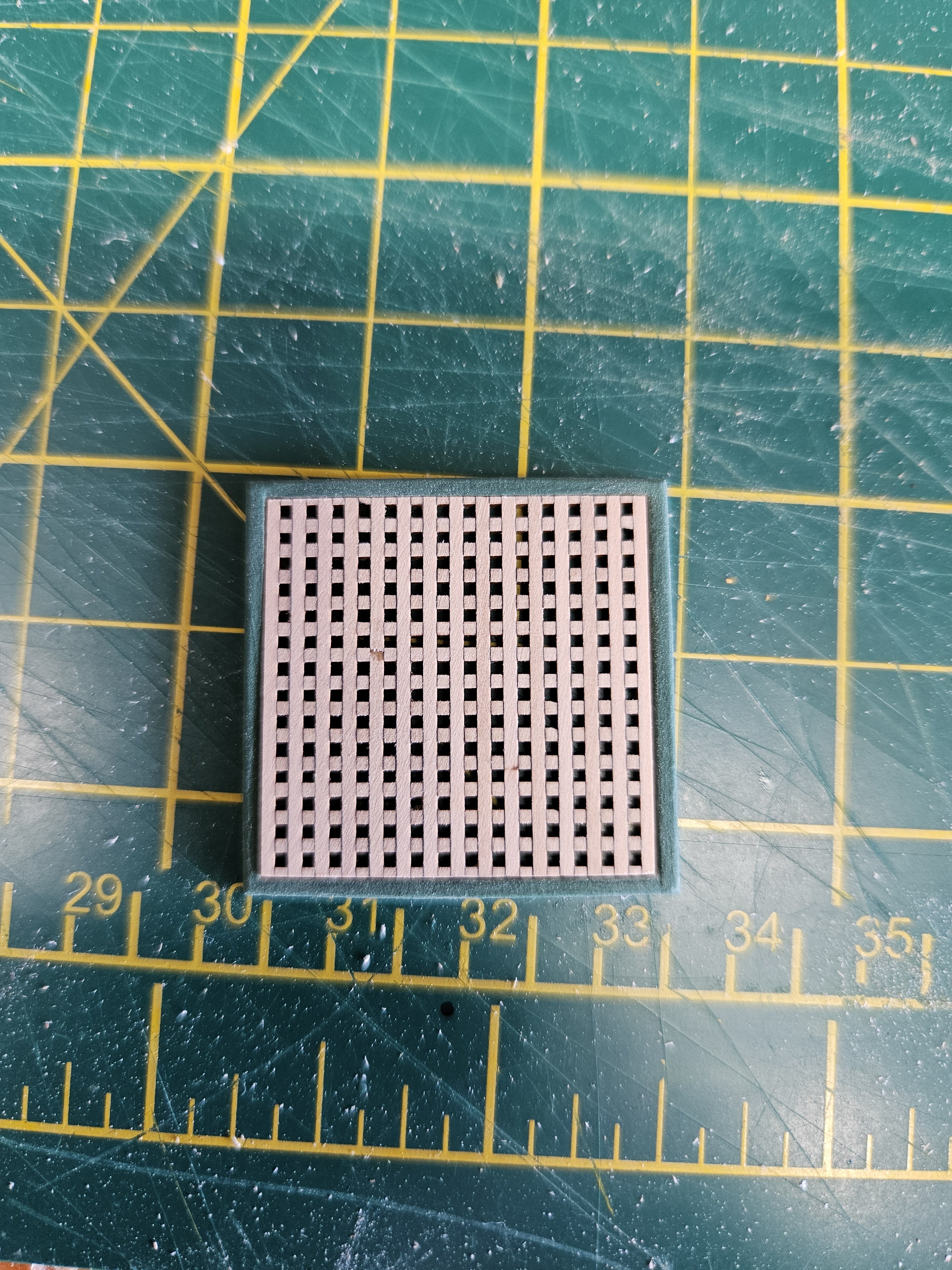
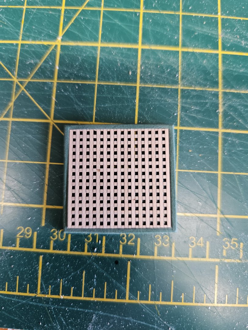
Yes, the 1:72 gratings. This is how mine came out.
-
I am back. The construction project (Sunroom) is, for the most part, complete and I can now refocus on the Connie. Looking back to the last picture, I have some work to do on updating those. The orlop decking is complete and I am in the process of installing the gratings and coamings on the deck.
-
@Avi I found .03 thick gratings (1:72 scale) from drydockmodelsandparts.com. That, on a 1:96 scale, comes to 3 inches, which is pretty dang close to accurate, and the "holes" are square. They are made from boxwood so they can be sanded, stained and varnished to your liking.