HOLIDAY DONATION DRIVE - SUPPORT MSW - DO YOUR PART TO KEEP THIS GREAT FORUM GOING!
×


Brian Falke
-
Posts
99 -
Joined
-
Last visited
Content Type
Profiles
Forums
Gallery
Events
Everything posted by Brian Falke
-
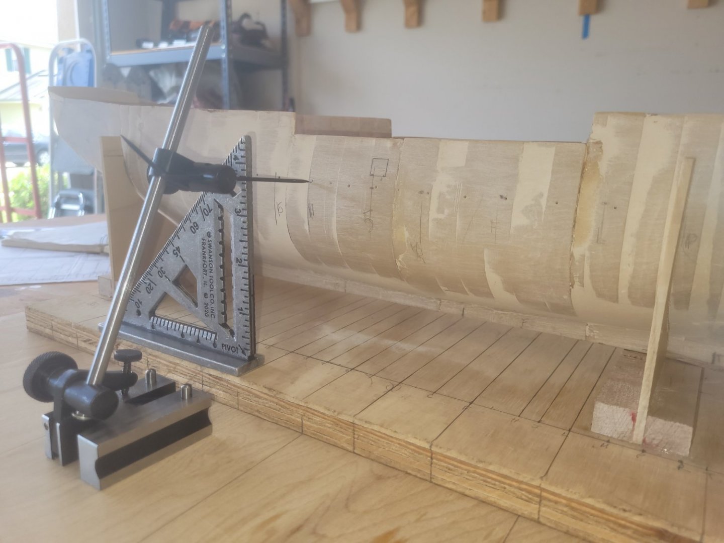
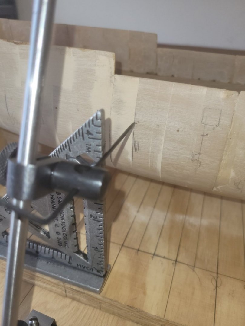
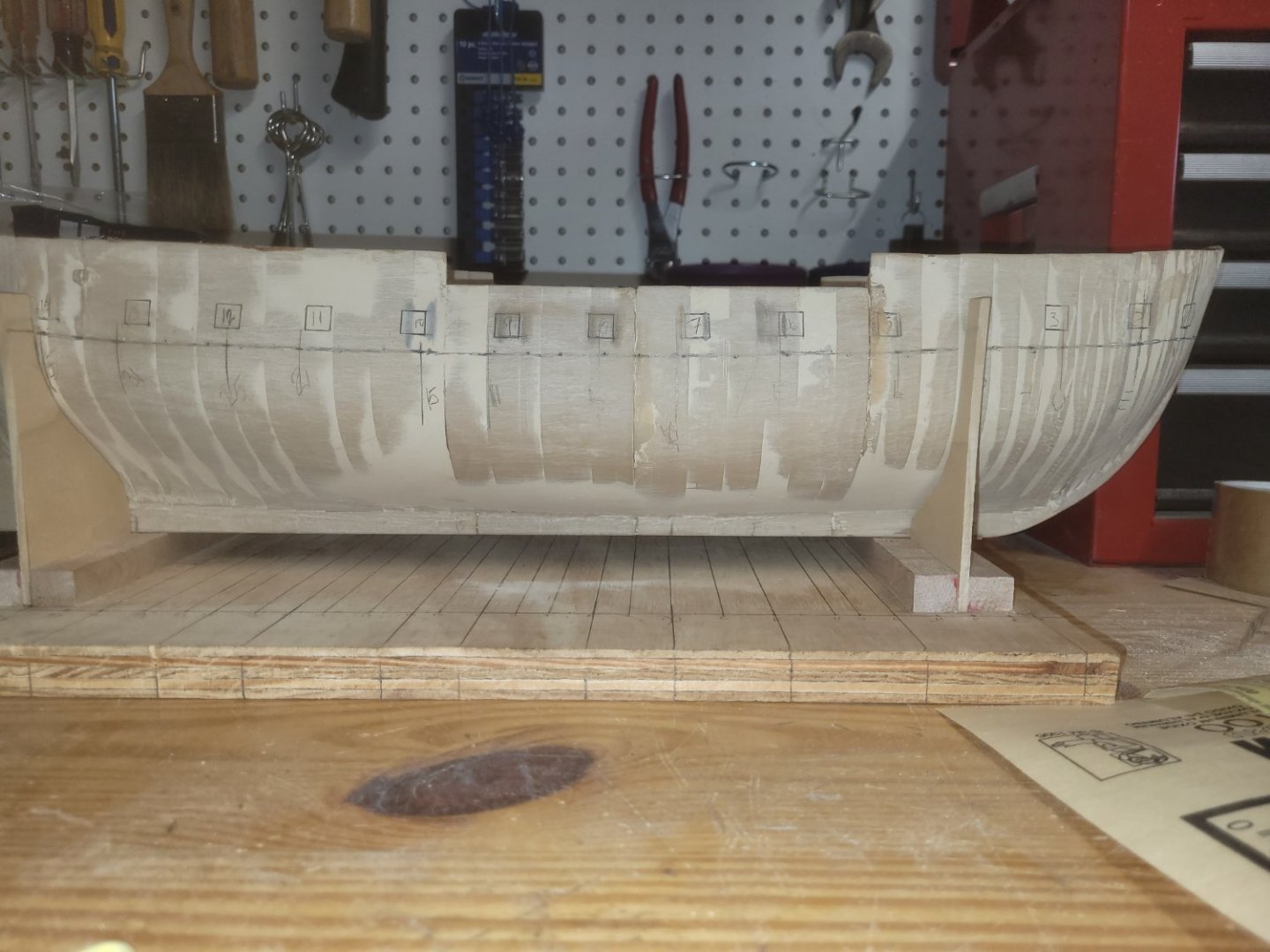
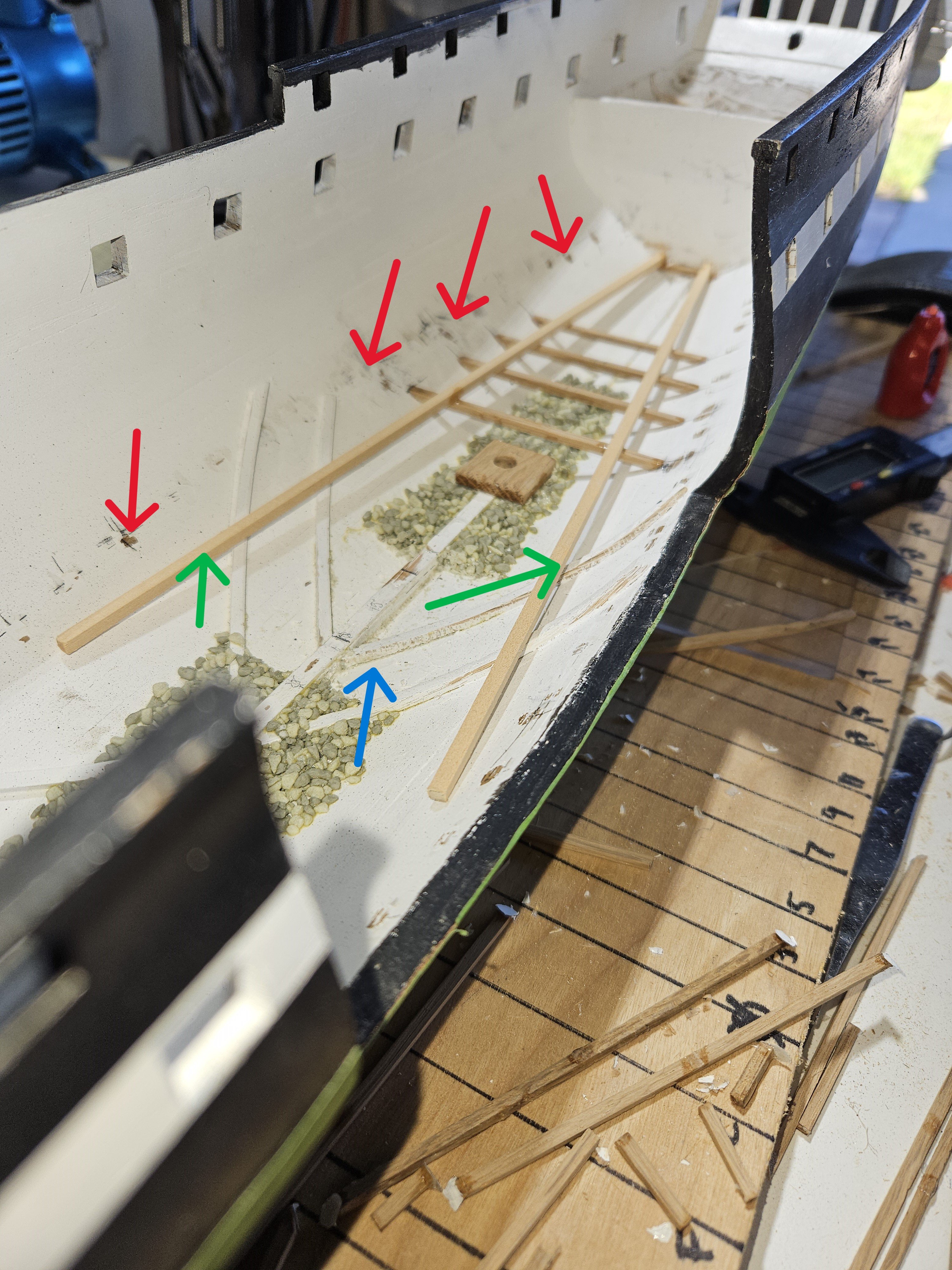
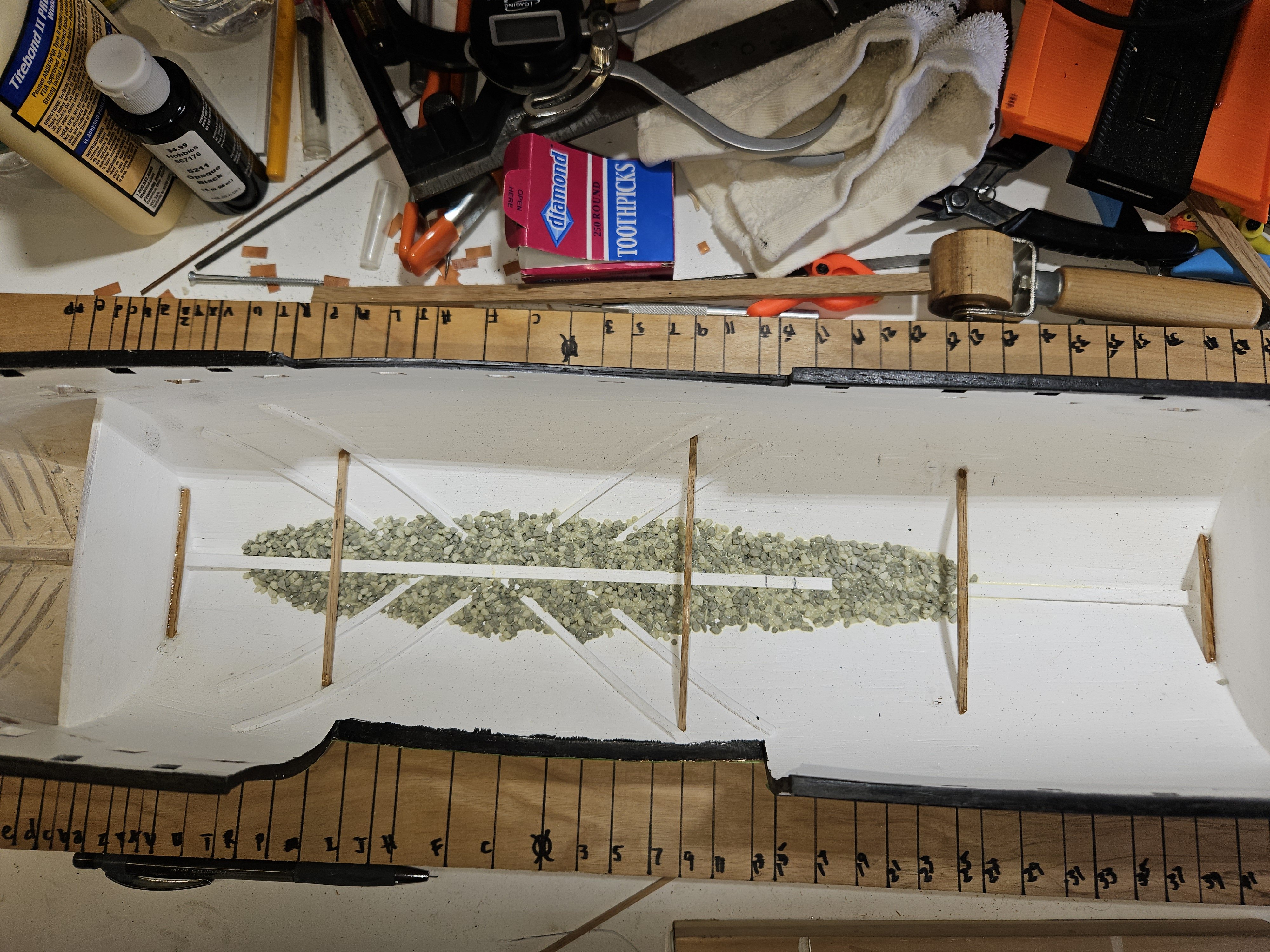
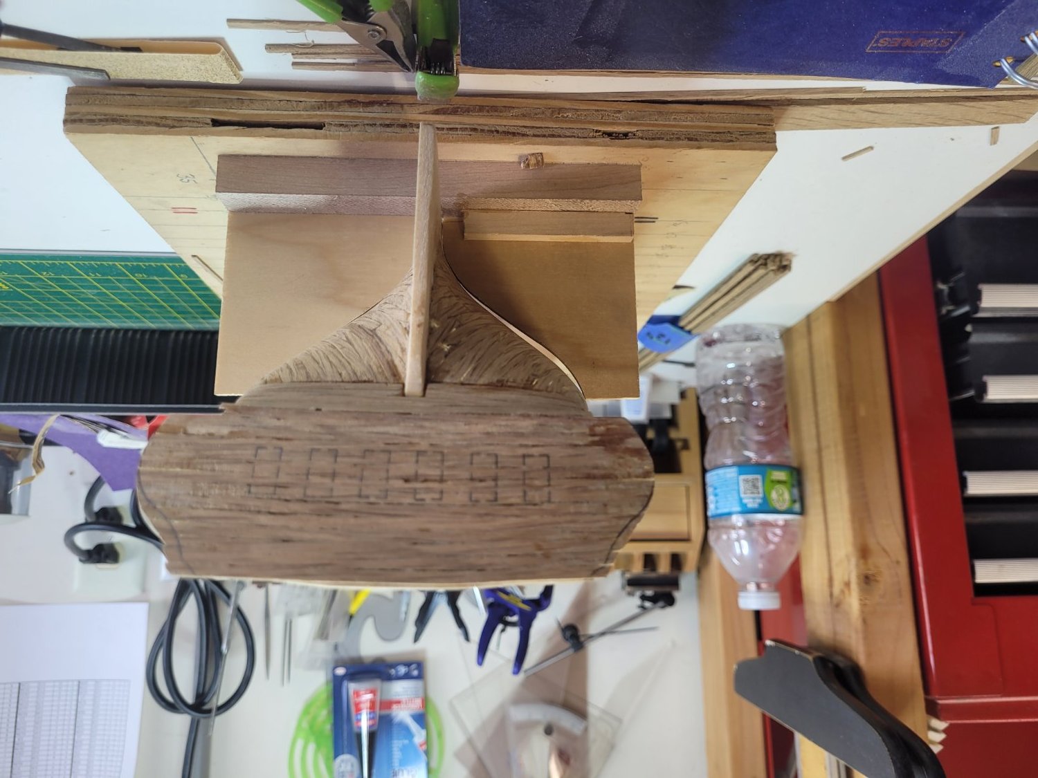
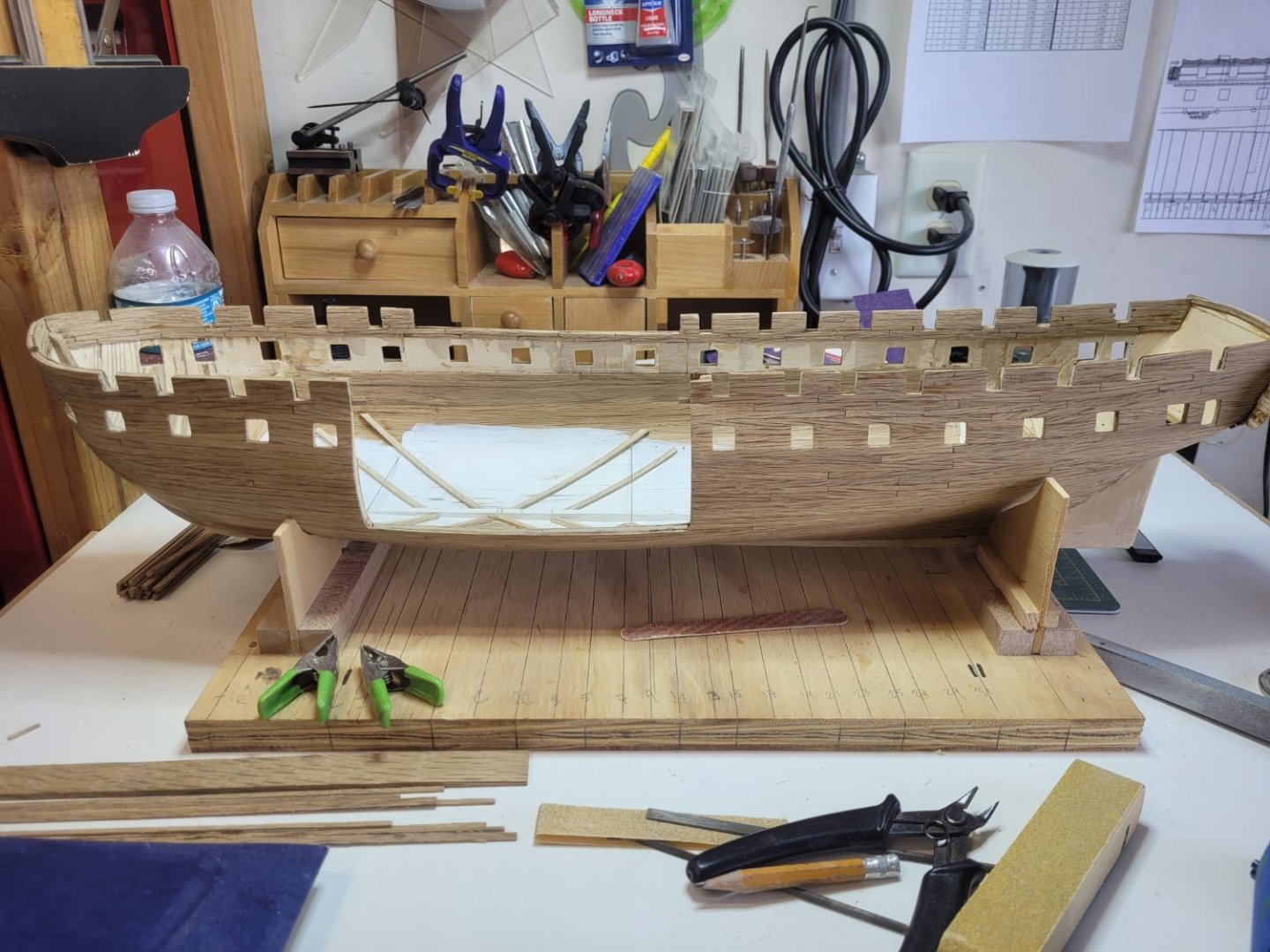
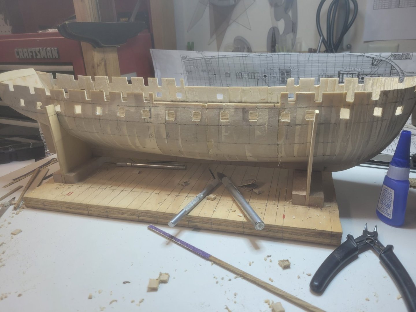
Shipyard all clean and organized...at least to the point where I can continue working on the ship. In the below picture, you will notice I removed a section of the ballast (blue arrow). That was because I was using the Pook's drawings from 1849. It had chain and shot lockers there, So, I removed them before doing a little more research on the drawings. Those were in preparation for Constitutions Mediterranean cruise and not representative of the Orlop deck of 1812. So, I will have to put the ballast back in there. Additionally, I last left off that I was moving onto the casks. Kind of got ahead of myself there. I stepped back and determined my next move would be to install the orlop deck beams. That did prove challenging. I initially had the most forward and aft beam installed. From the aft I moved forward using Marquarot's book to measure space between the beams and height above the bilge. The red arrows is where, using that method the beams were. Once I installed them, I decided to validate by measuring from the top rail down. As you can see, the Orlop deck beams were a little too high. I removed them. In addition to being too high, I found that I had a "wave" of sorts. One side of a beam would be higher than the other, and this carried onto the subsequent beams. The challenge I face was how to install the beams so they were level athwart ships and with the forward and after beams. I meticulously re-did the most aft beam and the most forward beam just aft of the most forward part of the top rail. When I had those positioned I glued two square pieces of stock (green arrows) to each beam as far to each side as possible. This allowed me to use them as a consistent guide, level side to side and forward and aft. The picture shows going from aft forward. I followed the same process forward aft.

-
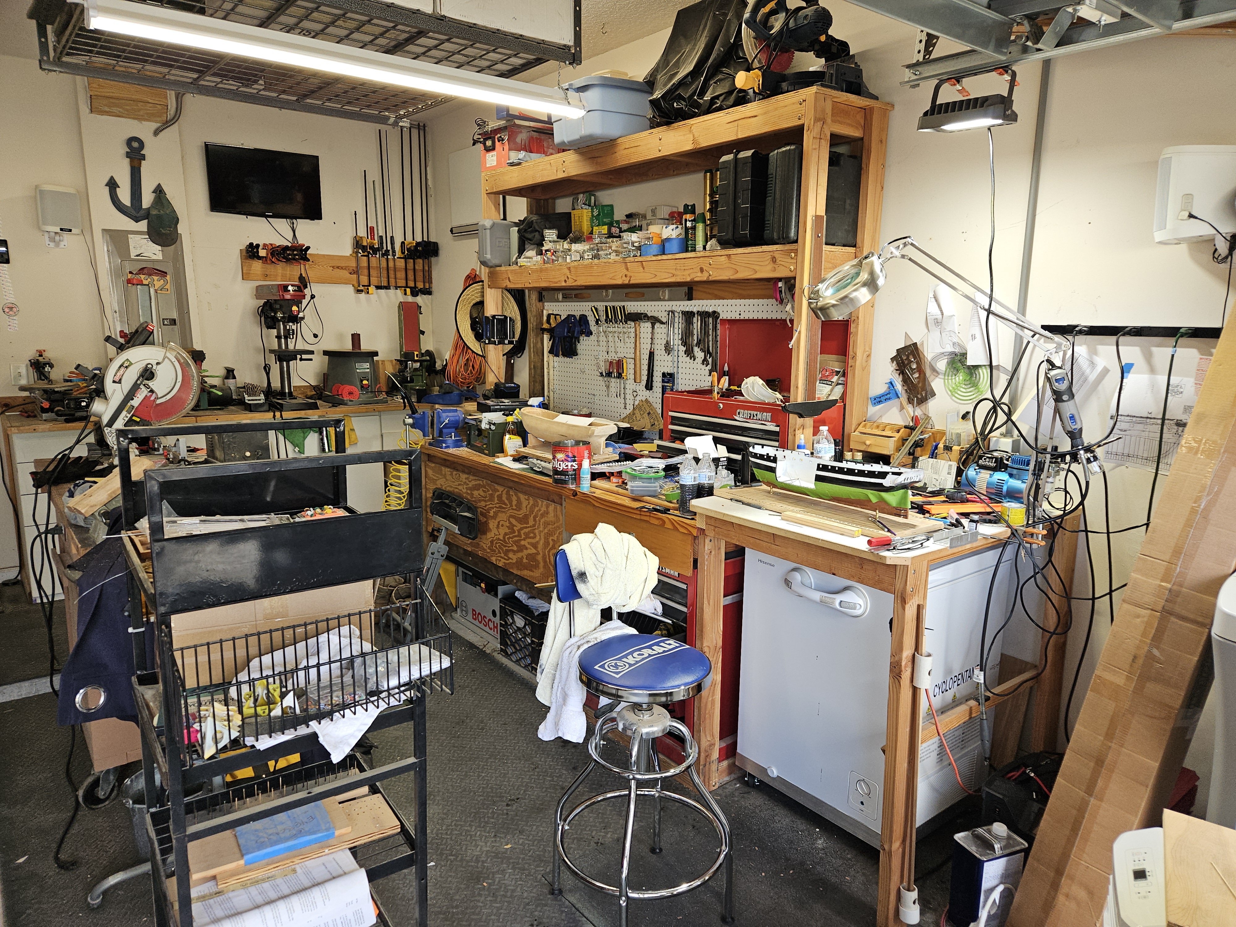
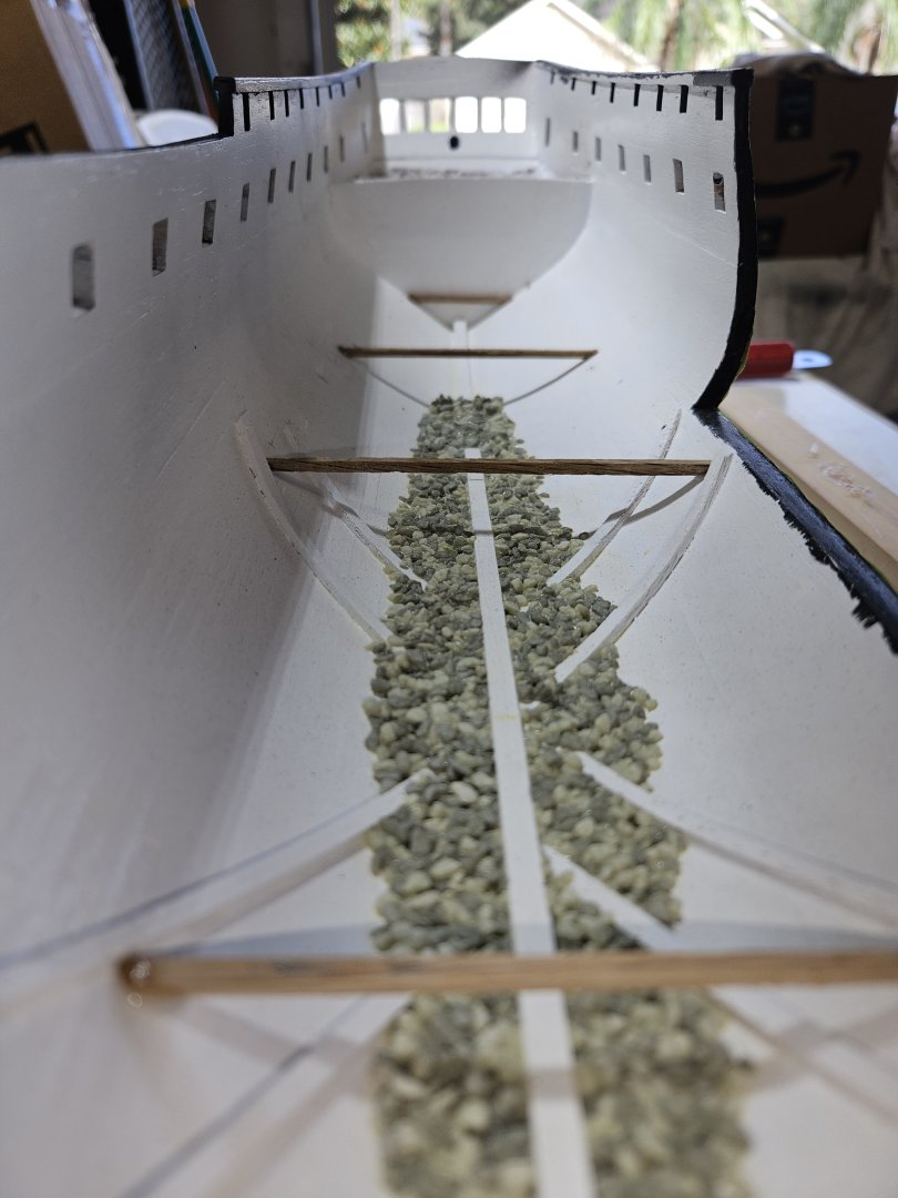
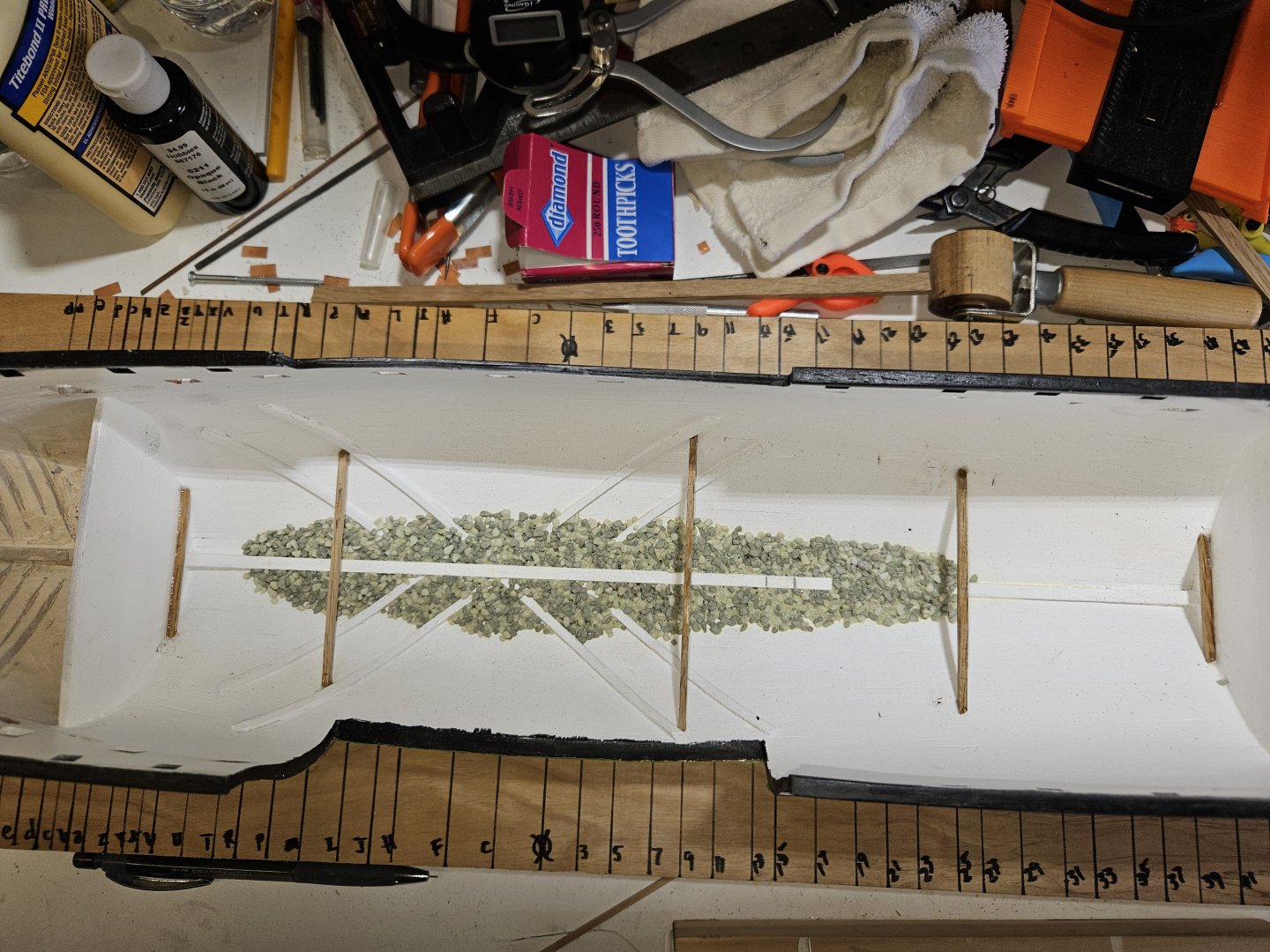
Commenced the Hold and Orlop deck. At this point, have 5 beams for the Orlop deck and the ballast. I found small gravel, which at scale came out to about 1' boulders. Filling in the hold area with the grave level to the keel, I then used diluted wood glue to set them. Next is to start with the casks (which I made using the 3D printer). But, before I move onto the casks, I do need to field day the shipyard. Getting a little out of control.

-
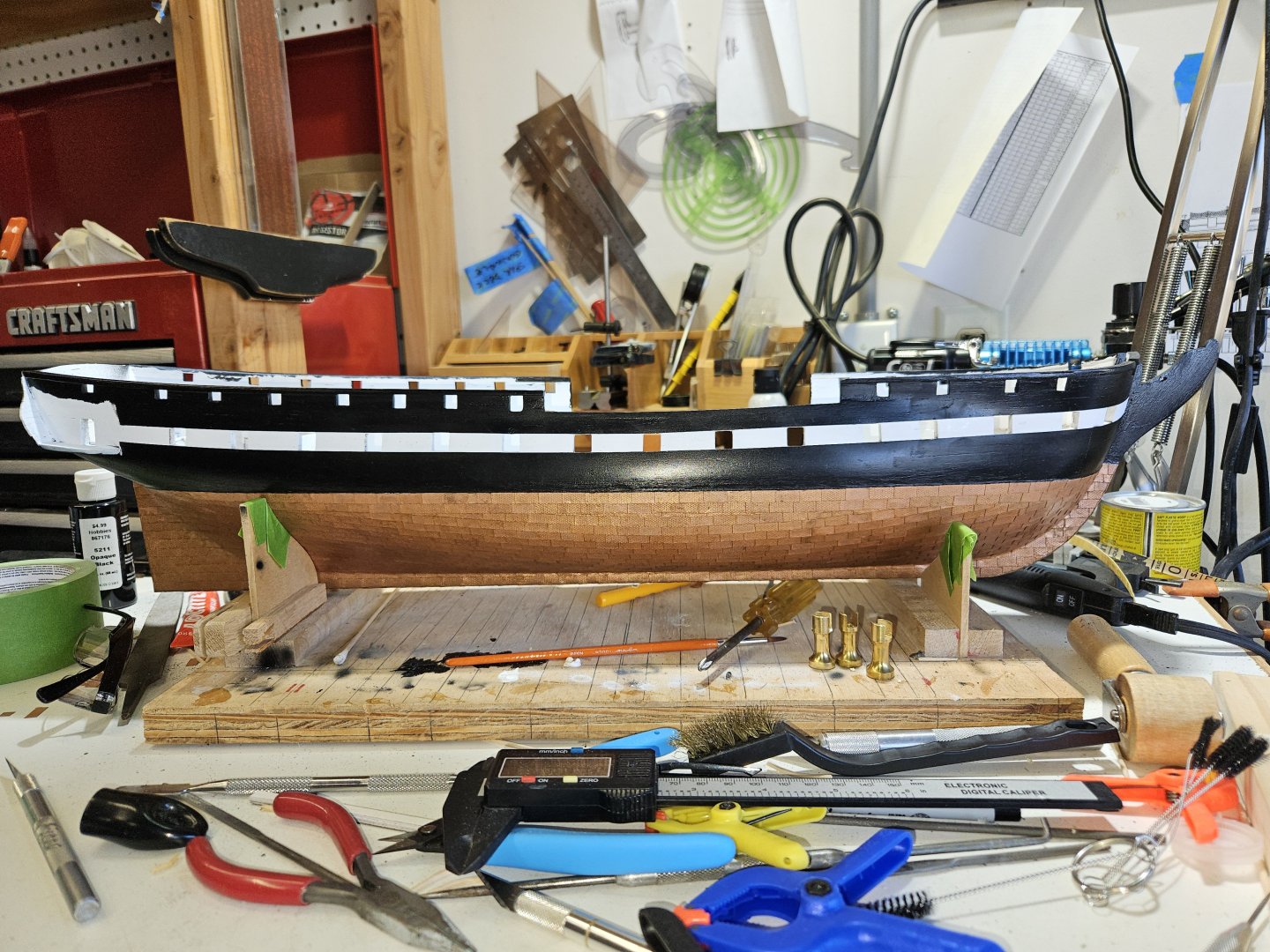
Thanks for the tip @MrBlueJacket. I did consider that, especially after trying to glue them on with superglue, then the glue I used for the plate, then JB Weld metal glue. I ended up attaching each gudgeon separately and while attaching one, I would detach another. It became quite frustrating. My last option was to use JB Weld Superweld glue. This allowed me to patiently position the piece, then apply the glue, make any final adjustments and then with the ultraviolet light, cure the glue without disturbing the previously positioned gudgeons. Here are the gudgeons without the hull bands attached yet. Using the same glue, JB Weld Superweld, I attached the bands. Here is the final. Now that the rudder is attached, I have mounted the model on a temporary base with the pedestals. I would post a picture, but embarassingly, I mounted the ship backwards. Once I turn the ship around, will commence on the Hold and Orlop deck. Cheers

-
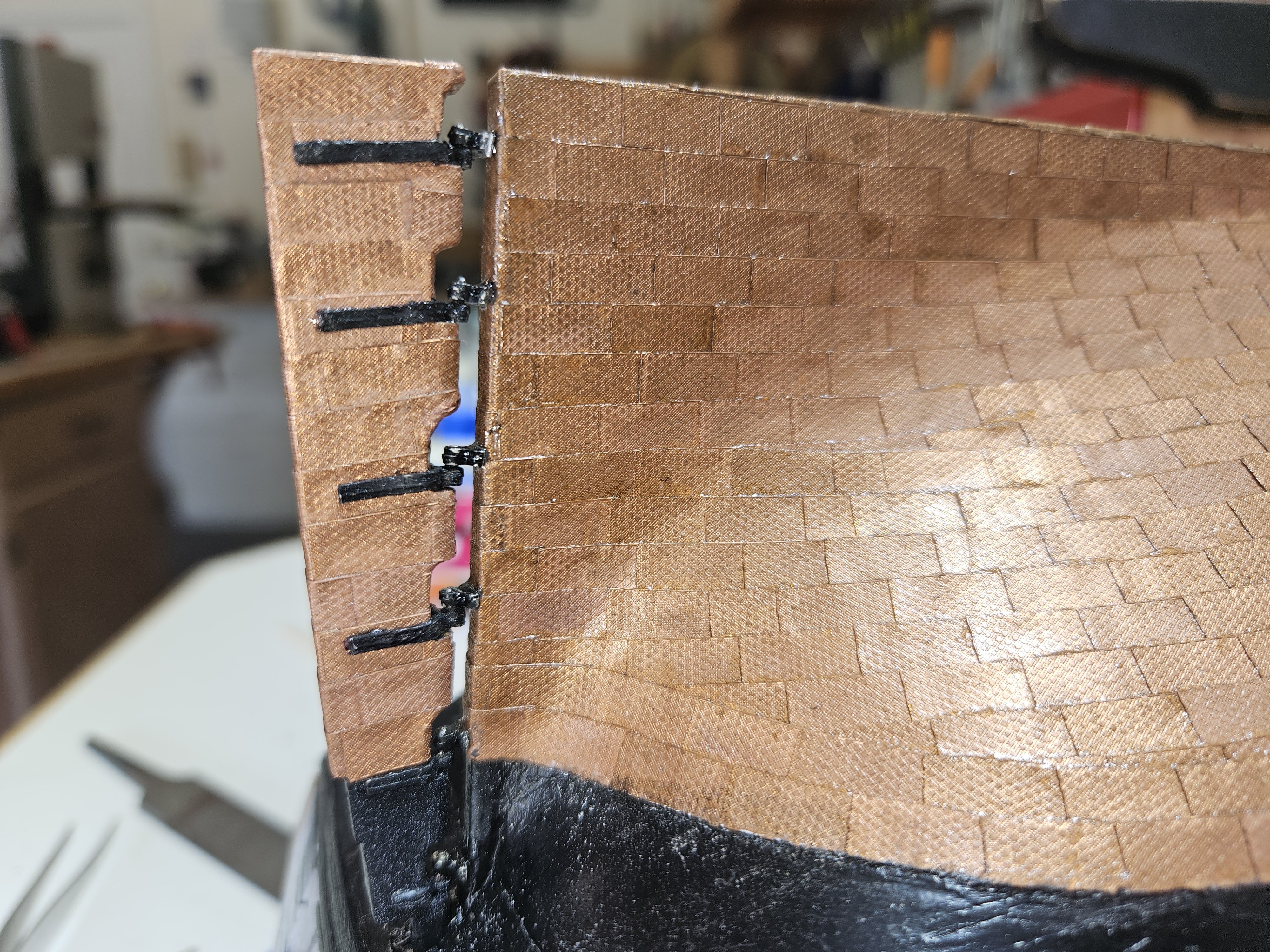
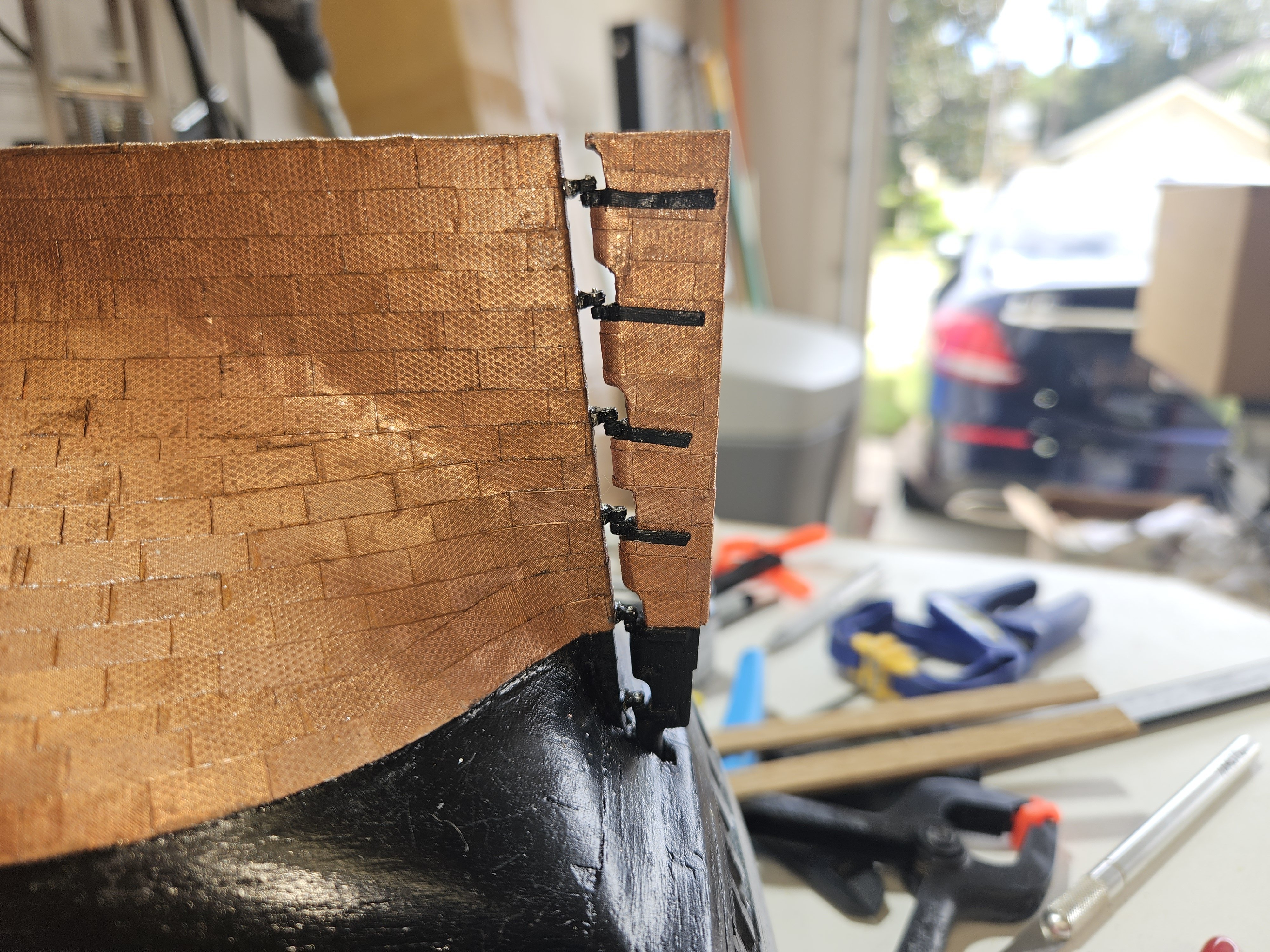
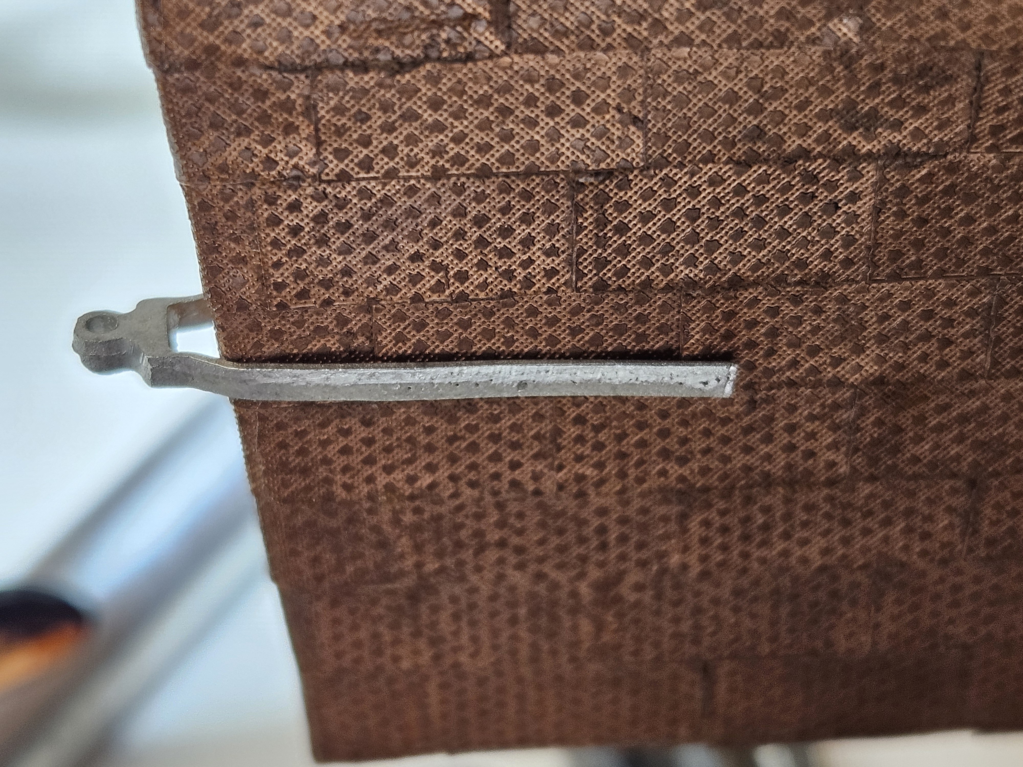
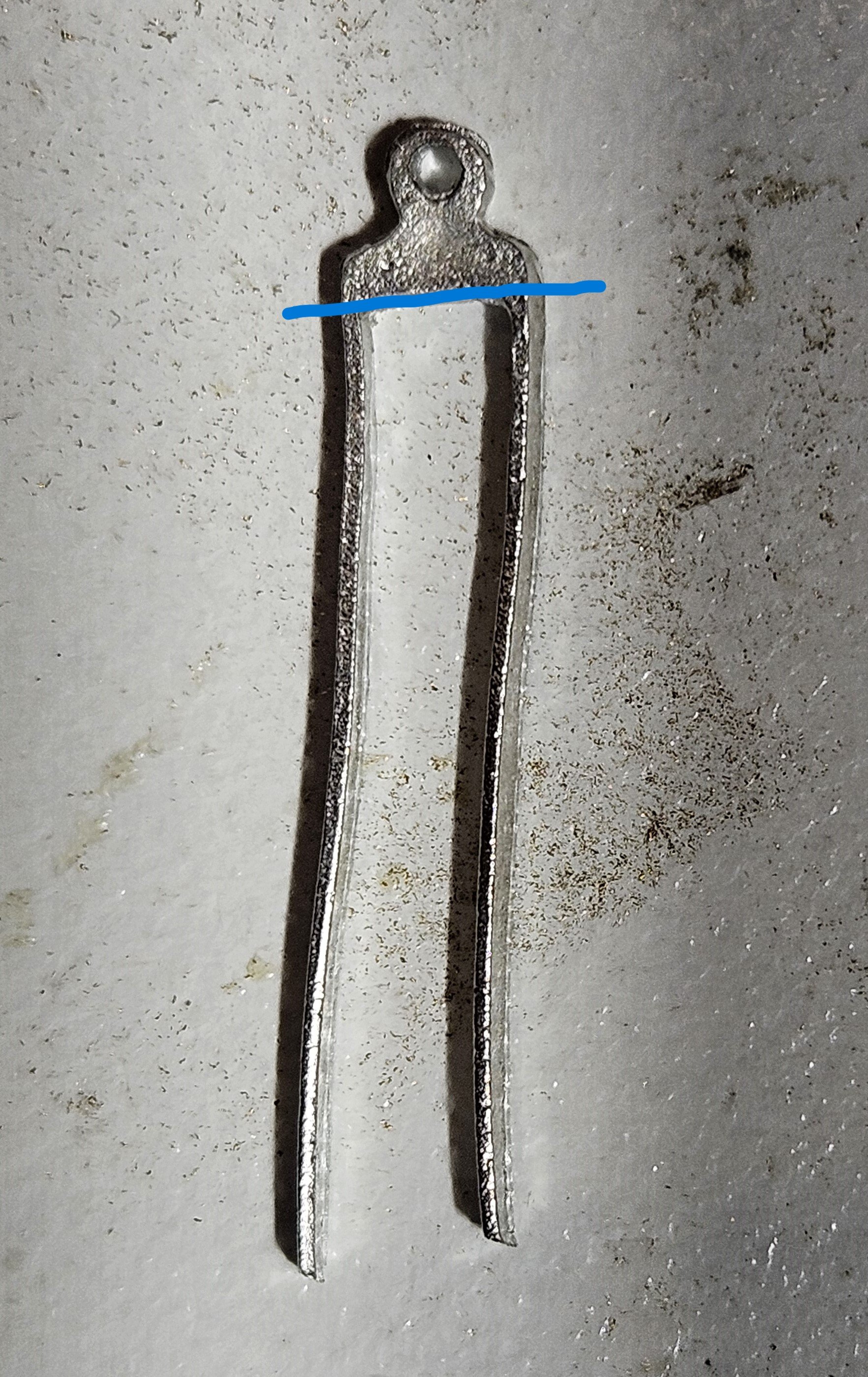
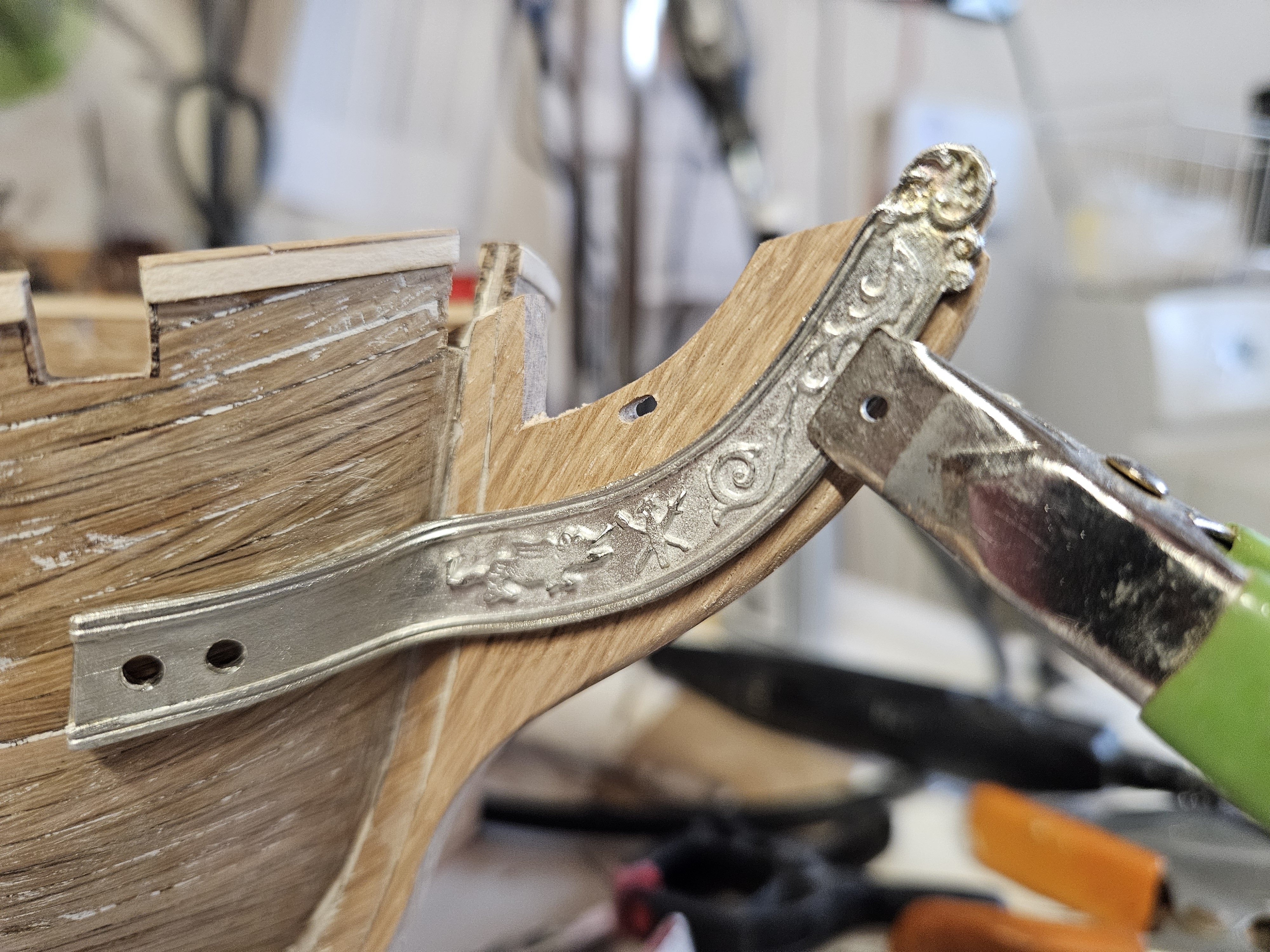
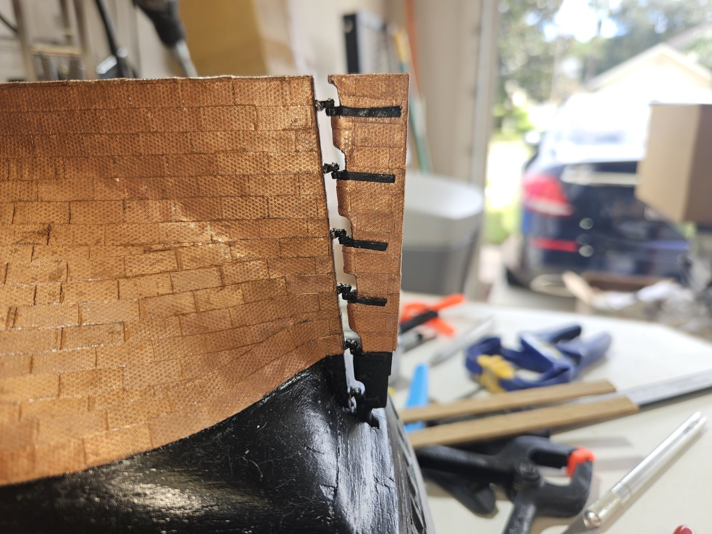
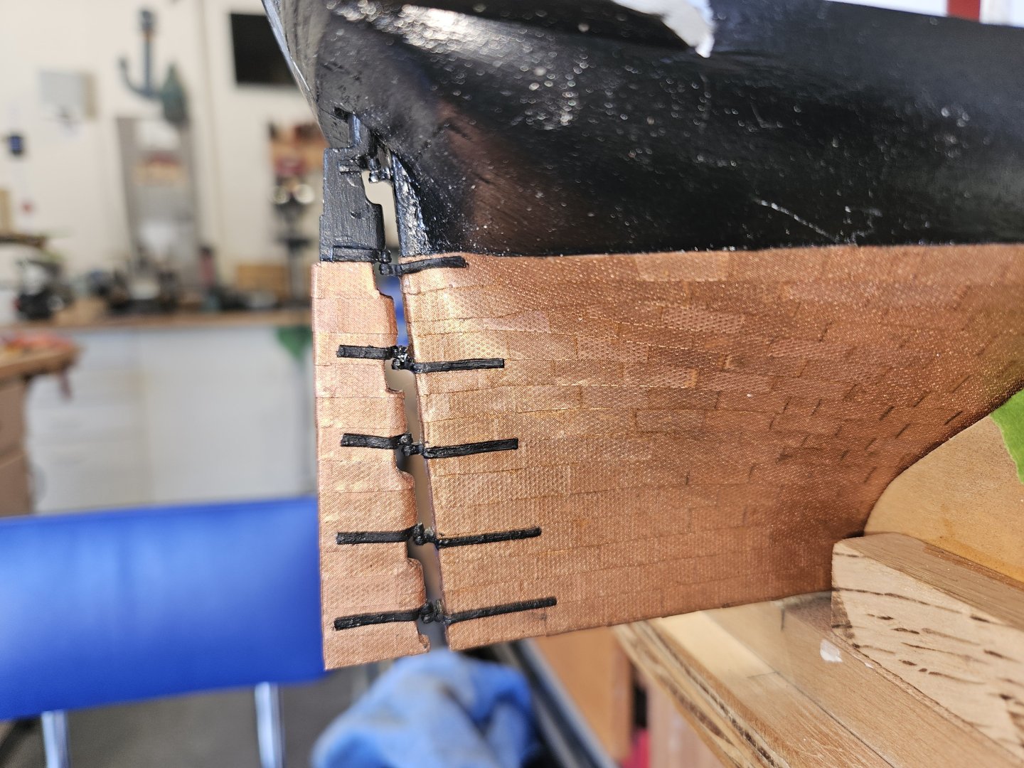
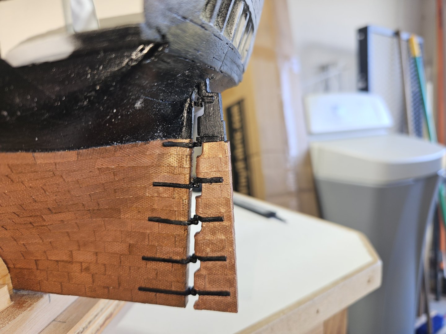
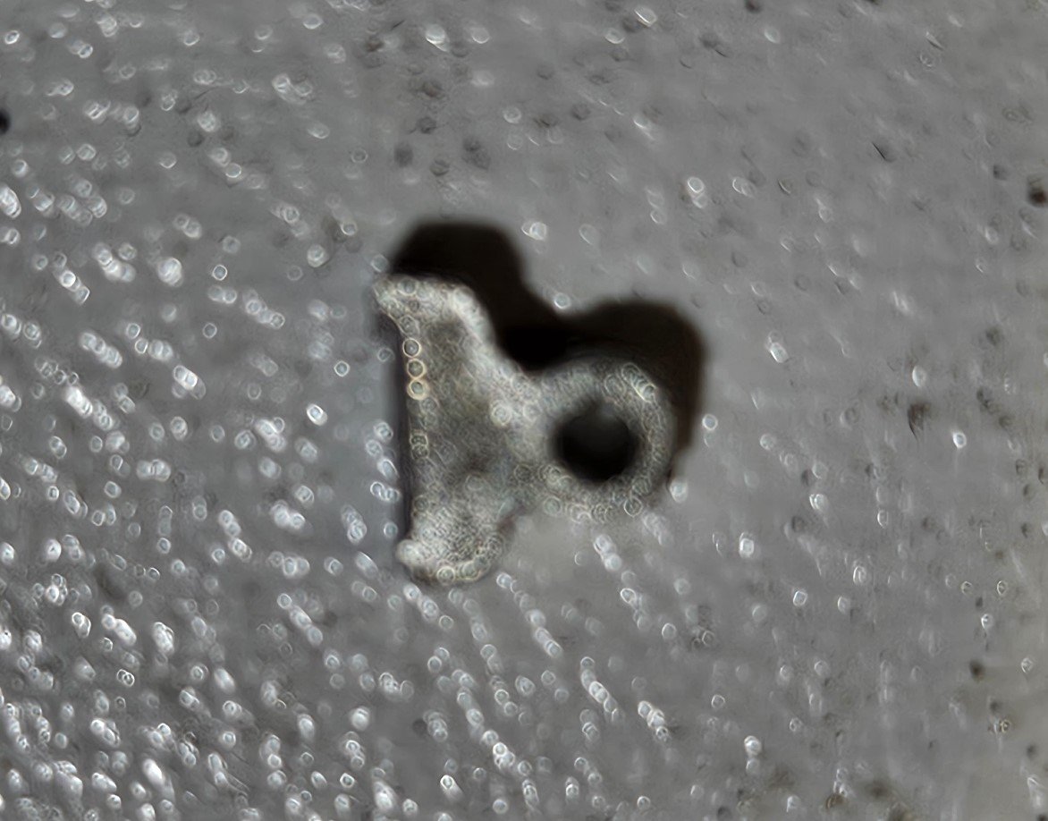
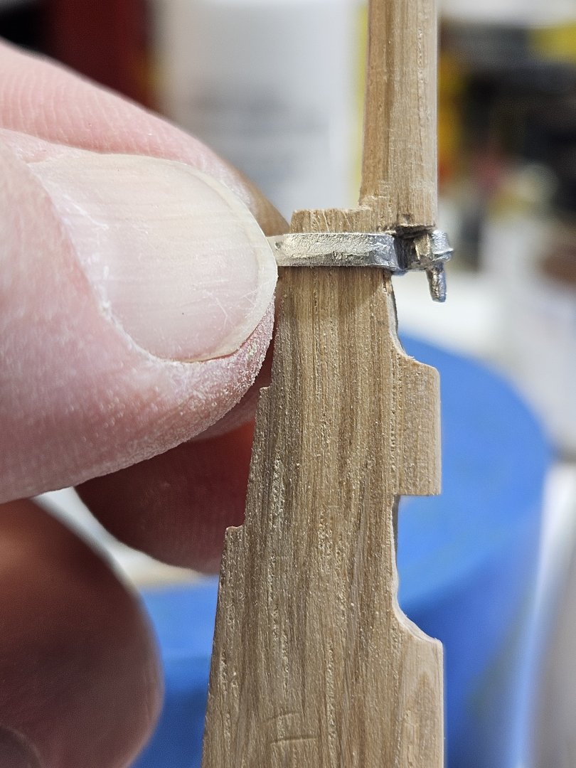
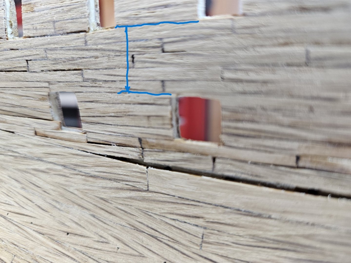
I have finally completed the coppering of the underwater hull. I did overlap from bottom aft, to forward and then up. After attaching all plates, I again went over the entire copper platting with the roller to ensure no corners were bent up or out. I applied two coats of satin polyurethane. Overall, it came out very nice. And, for the most part the hull painting is complete as well. I think I did that 3 times. Just was never satisfied with the results. My next move is to ship the rudder. I do feel the gap for the pintels and gudgeons are too narrow. I was able to "convince" the pintels to fit onto the rudder. However the gudgeons is a different story. I did read on another build log that the builder ordered smaller sized pintels and gudgeons which could be manipulated more easily to fit the rudder and sternpost. I am taking a different approach. If it does not work out, then I will order the smaller size. The first picture is the gudgeon on the sternpost. As you can see, it will not fit, too narrow thus leaving a gap where gudgeon does not meet flush with the sternpost. I have cut the two bands that attach the gudgeon to the hull and then will attach just the gudgeon to the aft portion of the sternpost. After the glue has cured, I intend to then attach the bands to the side of the gudgeon and the hull to appear as if it is one piece. The blue line is where I cut the bands off of the gudgeon. I saved them as I will be using them. To install the gudgeons, I have them on the pintles with the rudder upside down. I will then turn the hull upside down and then place the rudder in its proper position, clamp it, and then glue the gudgeon to the sternpost. Once the glue has cured, remove the rudder and then attach the bands and file to appear as if it was never cut. If this does not work, then I am back to where others were, buying the smaller pintles and gudgeons. After installing the rudder, I will move onto the false keel. My plan is to complete all underwater hull work and then mount the model on the pedestals to work on the interior, starting with the hold. Cheers, Brian


-
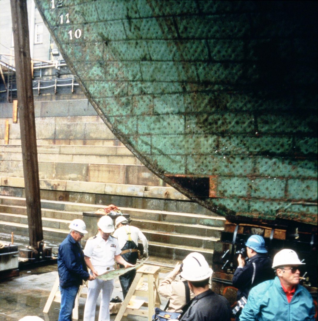
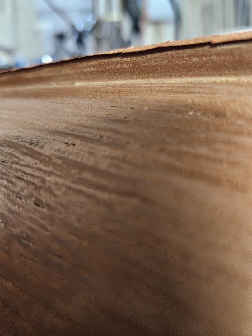
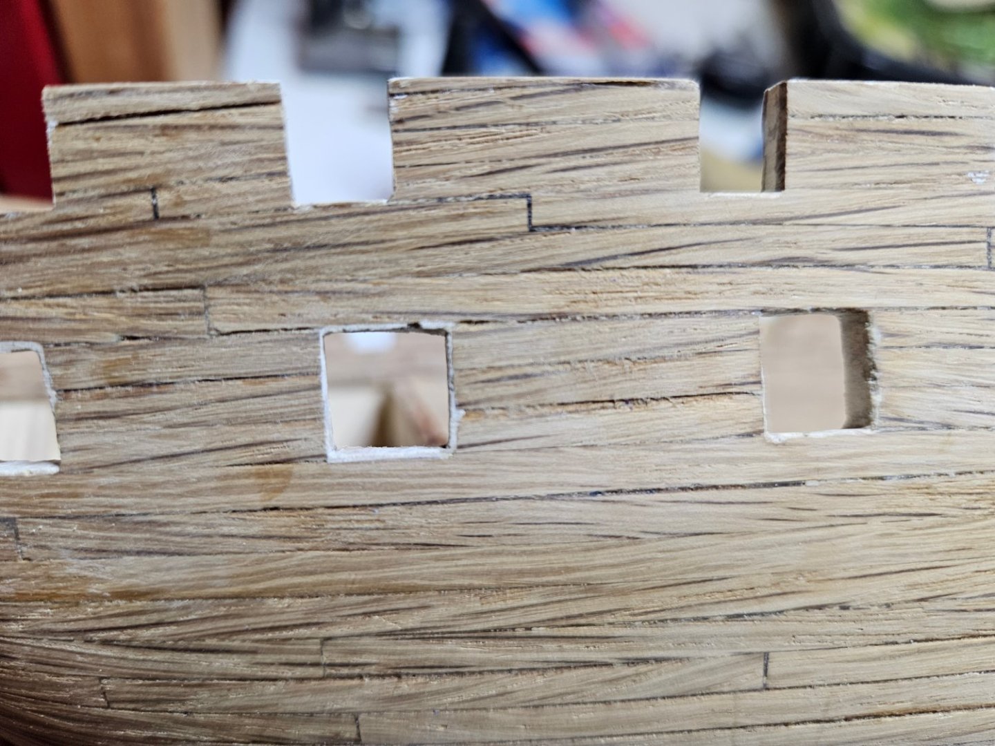
Got a question to all regarding the actual coppering on the current CONSTITUTION. Why are the plates overlapping with the lower plate overlapping the higher plate? If you look at the plate that was removed in the attached picture, you can clearly see the non-weathered line across the upper plates and the aft plate. I have looked at pictures of the most recent drydocking and the plates are being installed from the waterlline down to the keel. I am just curious. The method in the instruction book, aft-forward, keel - waterline makes perfect sense when you envision the ship moving through the water.
-
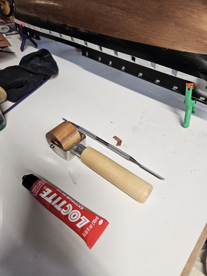
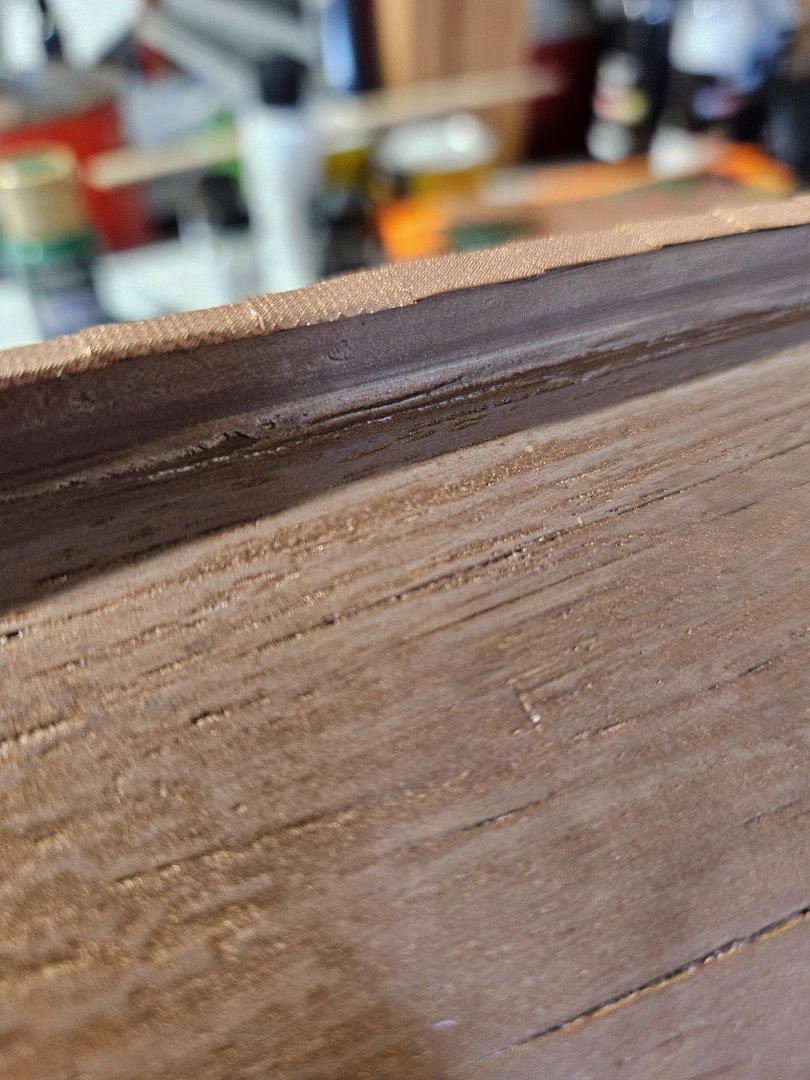
I have started the long and tedious process of coppering the underwater hull. I quickly learned that patience, a steady hand, and the right tools are key in making the coppering look good. I am using LOCTITE Extreme Glue as the adhesive. It provides an excellent bond additionally, allows me to reposition the plate up to about 5 minutes after attaching to the hull. I place a small drop on the hull where the plate will go and then using the stainless steel tool next to the roller I spread the glue to a thin coat. There will be excess glue on the tool so a small cup of mineral spirits is necessary to keep the tool clean. After spreading, I place the tool end in the cup of mineral spirits to clean (just let it sit in there). I then attach the copper plate to the hull. This is where a clean tool is necessary. Using my left thumb I gently roll on to the leading edge of the copper plate to hold it steady. Using the tool, I then press the plate down on to the hull. After that, using the same tool, I would nudge the plate slightly into it's final position to dry. After a group of plates have set for about 5 minutes, I then use the small roller to firmly press the plates onto the hull to achieve a "smooth" appearance. I have elected to overlap the plates, so they will not be perfectly smooth. I have just done the keel and two plates on the side. You will notice that the sides of the plates that are attached to the keel from about mid-ships forward are not bent around the sides. I found that trying to bend the sides upward caused the plate to shift and bend at the bottom of the keel. Allowing the glue to dry and then bend the plate works great. No shifting and no bending of the plate at the bottom. I started at the sternpost, and following the directions in the book, I am moving forward and up. I have placed the plates along the entire keel bottom and up the bow. A lesson learned here. I should have stopped coppering the keel at the point where the keel transitions to the bow stem. The plates at the bow stem should overlap those plates that are attached to the hull. If you imagine the ship moving through the water, the leading edge of the forward most plates on the hull need to be covered by the plates on the bow stem or they would eventually rip off the ship due to the water flow.


-
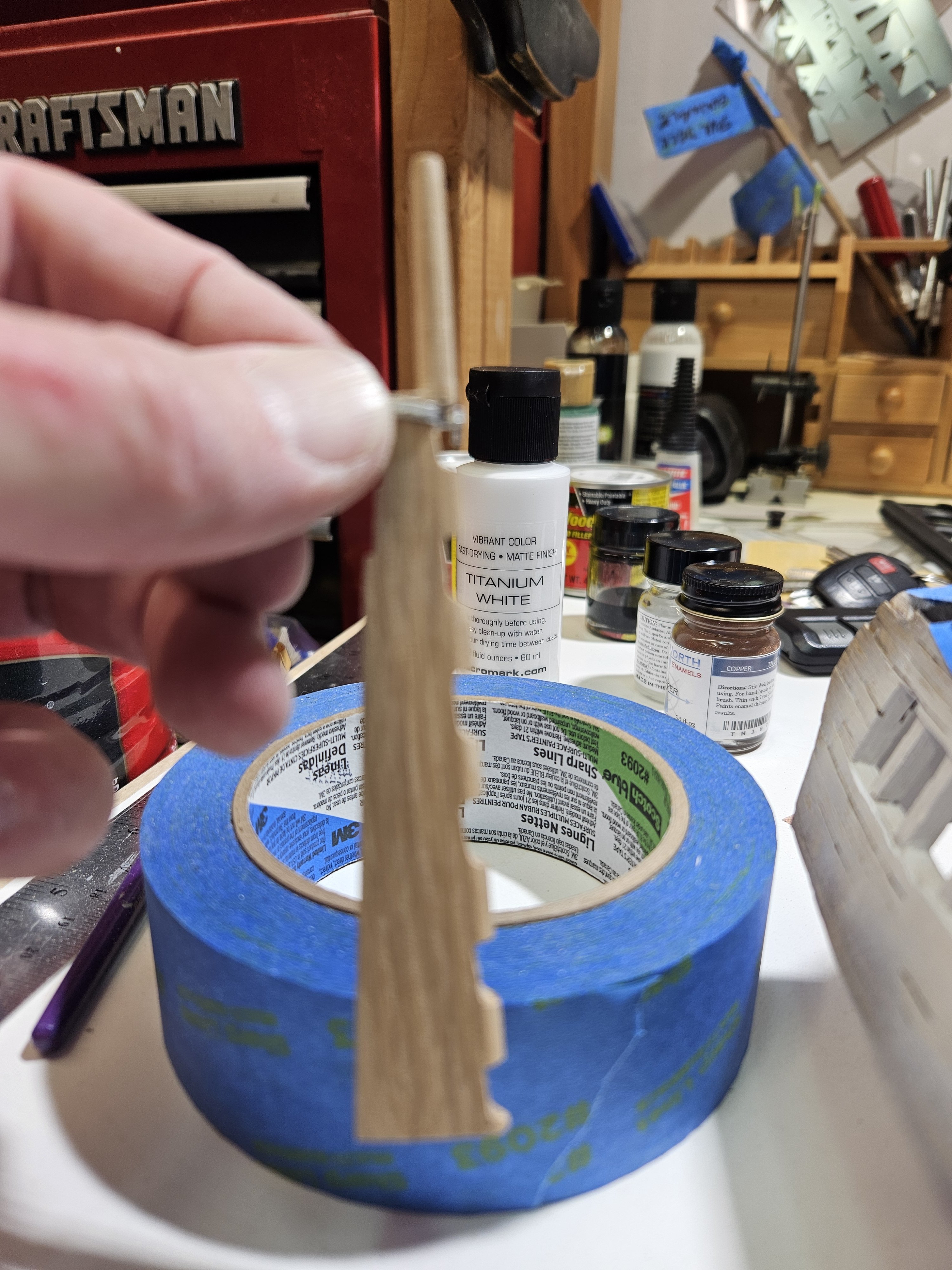
I have seen a lot of discussion on the site concerning the rudder and the pintles. Specifically, around the leading edge of the rudder. The first is, should it be square as depicted on page 16 or rounded as depicted on page 19? Also, should the pintles be "countersunk" into the leading edge of the rudder (as shown on page 19) or not? Using the details on page 19, I have decided that the leading edge should be rounded and the pintles countersunk so that the rudder is as close as possible to the sternpost. Using a table scroll saw I cut out the six notches for the pintle to sit in. Since I will be coppering the hull and rudder, I am not to concerned with smoothness of the rudder.

-
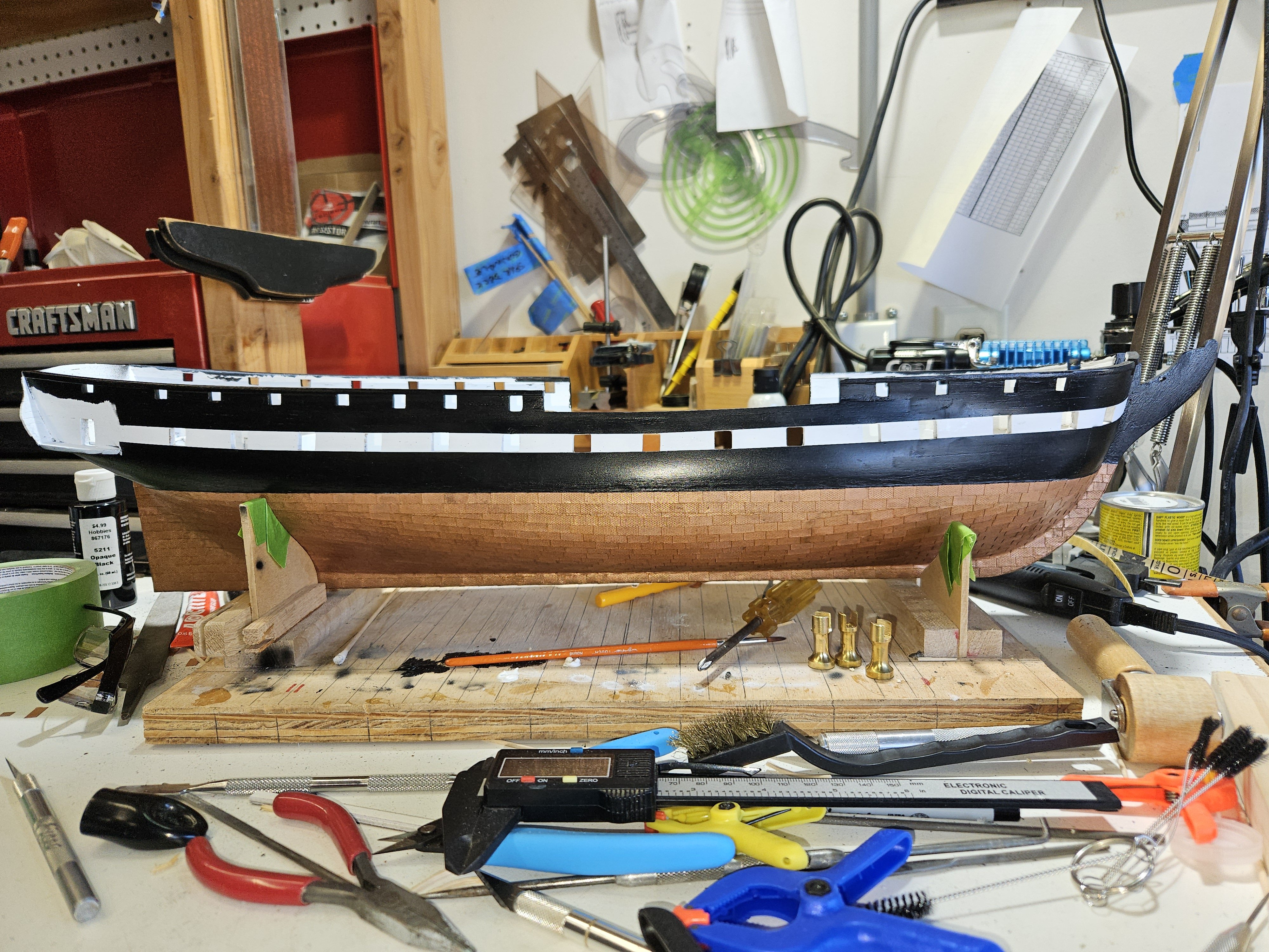
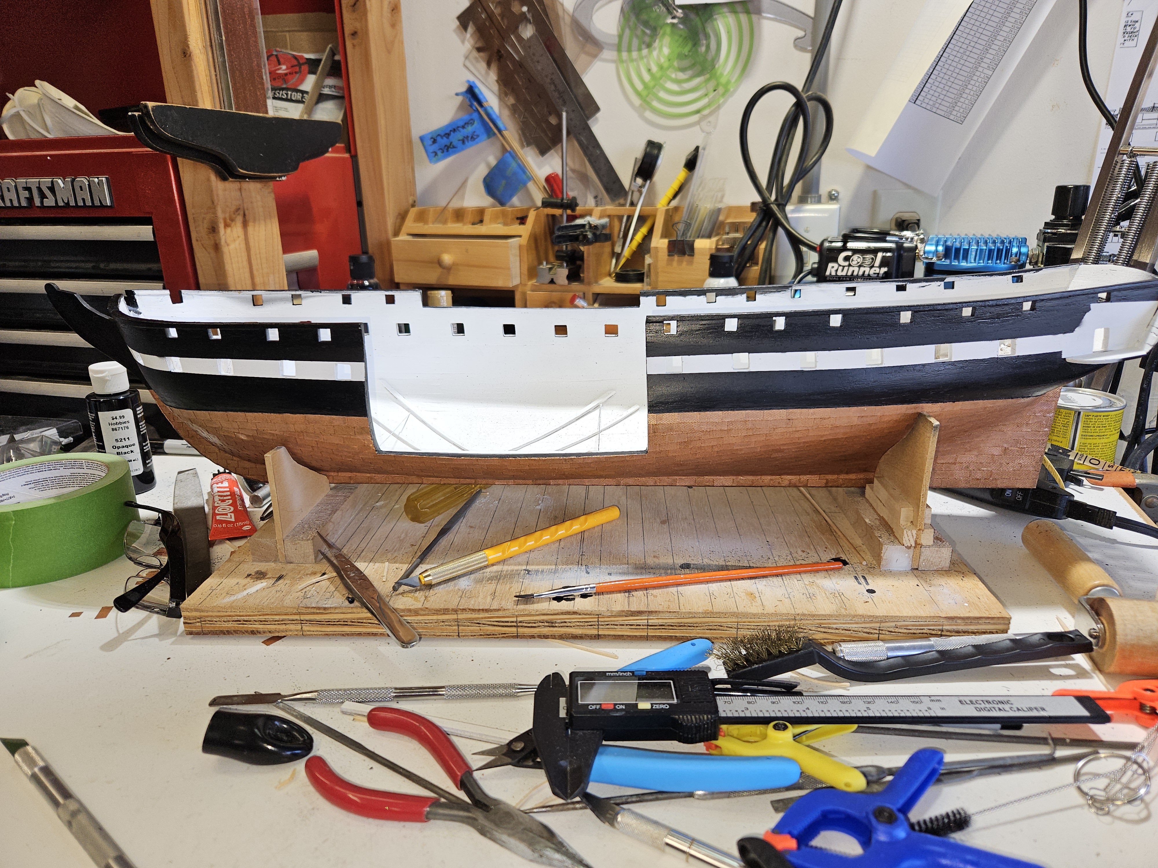
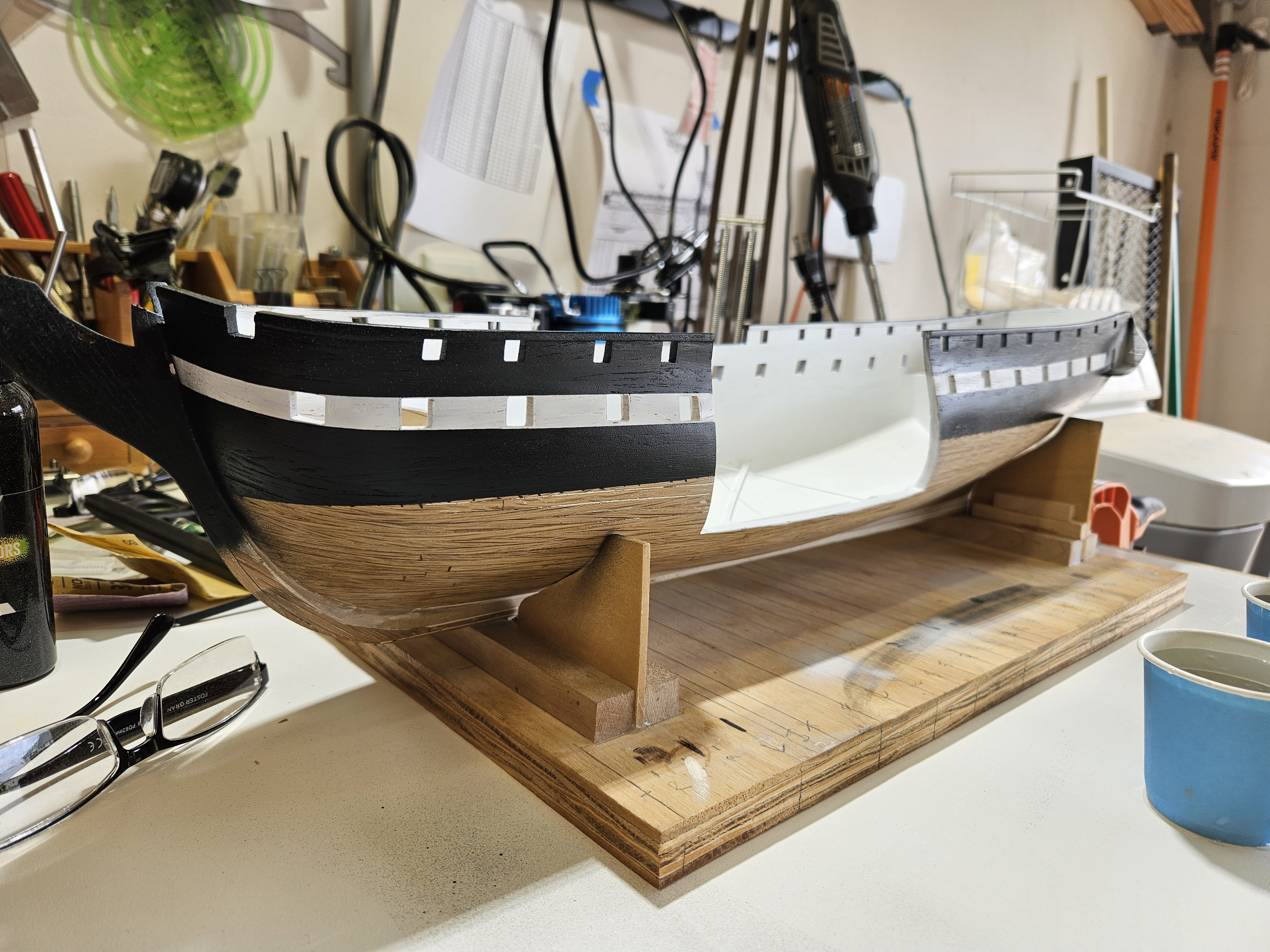
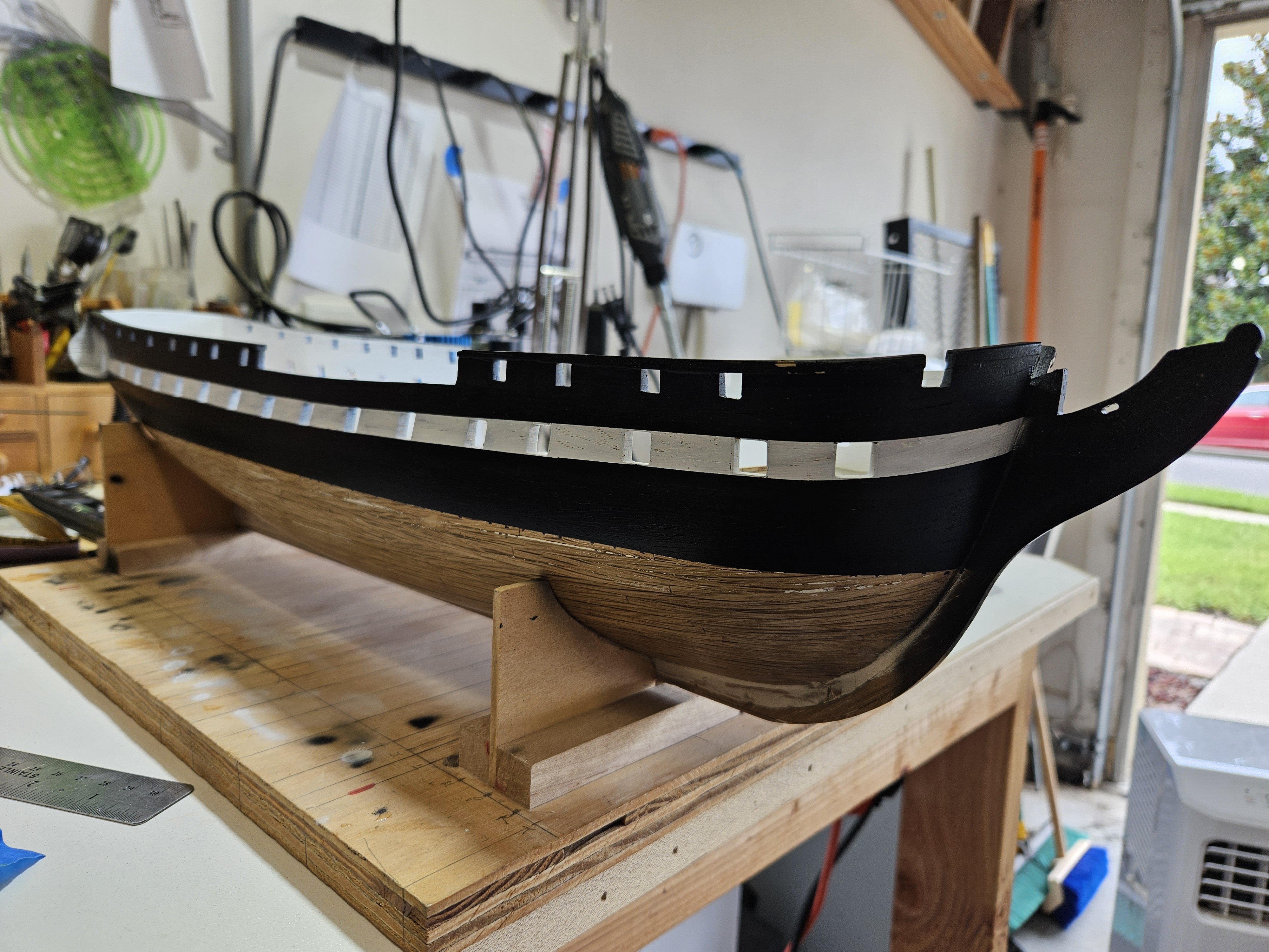
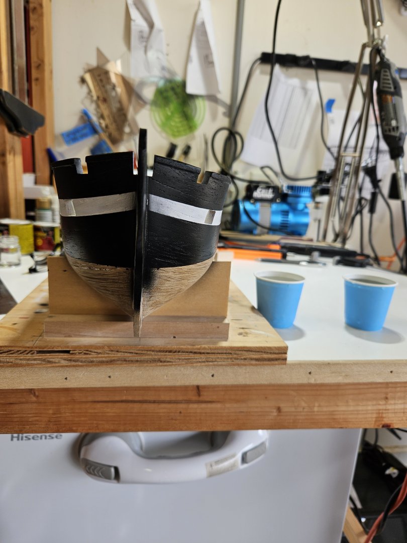
So, I know I said that I was moving on to coppering the hull...but, a new toy (read tool) came in and just had to use it. An airbrush. I will admit to everyone here that I am not the best at brush painting and find it very frustrating at times. So much so, that it will take quite a few coats for me to be satisfied. With airbrush, it was two coats and I was extremely satisfied. The pictures here are just primer, not the final. I will be adding the beading (which came in yesterday) on the hull, prime them and then paint. Then I will copper the underwater hull. If you look closely, you can see black dots just below the black paint line. Those mark the water line. I did struggle finding a way to raise the bow 1/4" and keep the ship plumb. I was finally able to glue together a 1/2" block and a 1/4" block with side support where the keel would snugly fit in so that the ship was plumb. The 1/2" block was used to raise and support the bow and the 1/4" was used to raise and support the stern section. Using the hull marker that I used to mark the gun ports, I set it to 3" and marked a tick with a sharpie along the port and starboard sides. I used the blue painters tape to get the paint lines and to prevent overspray.


-
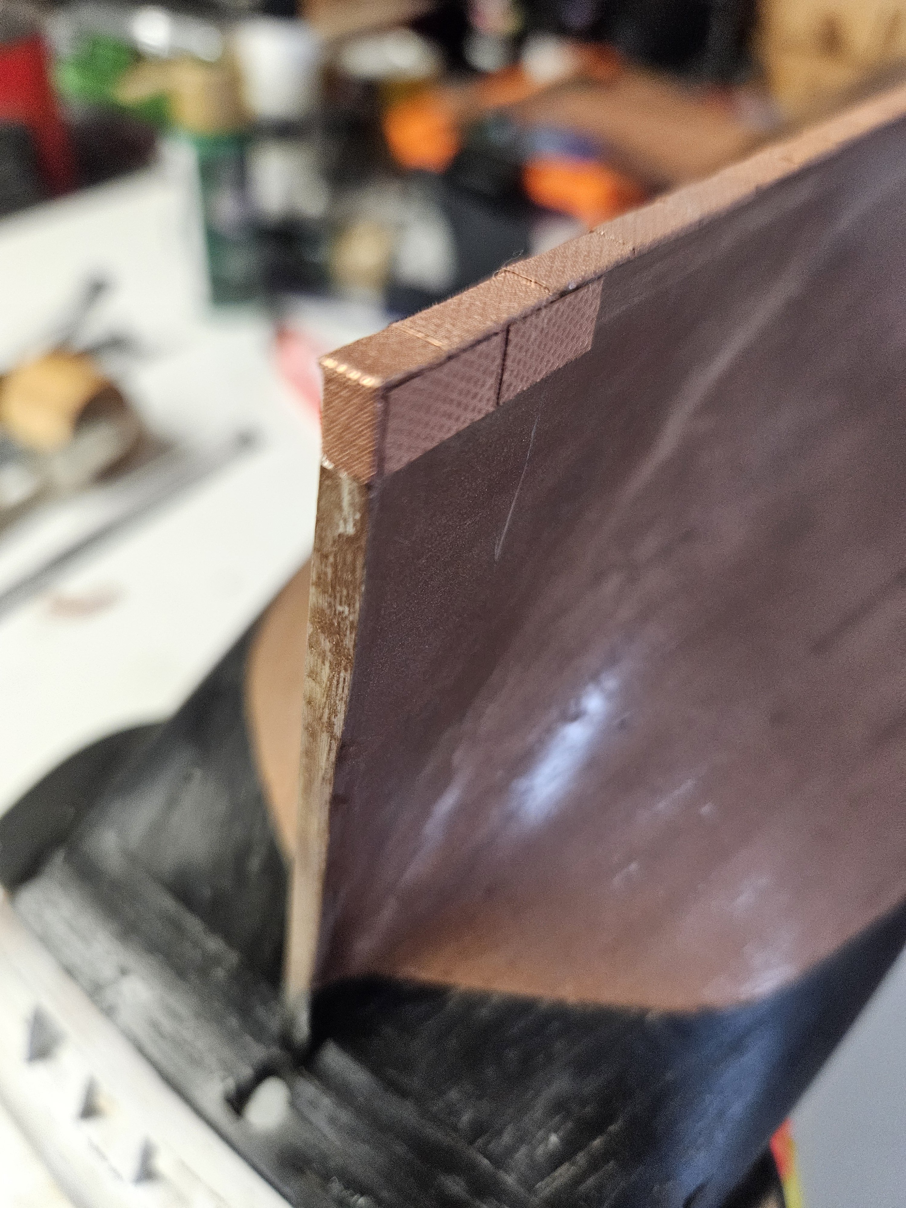
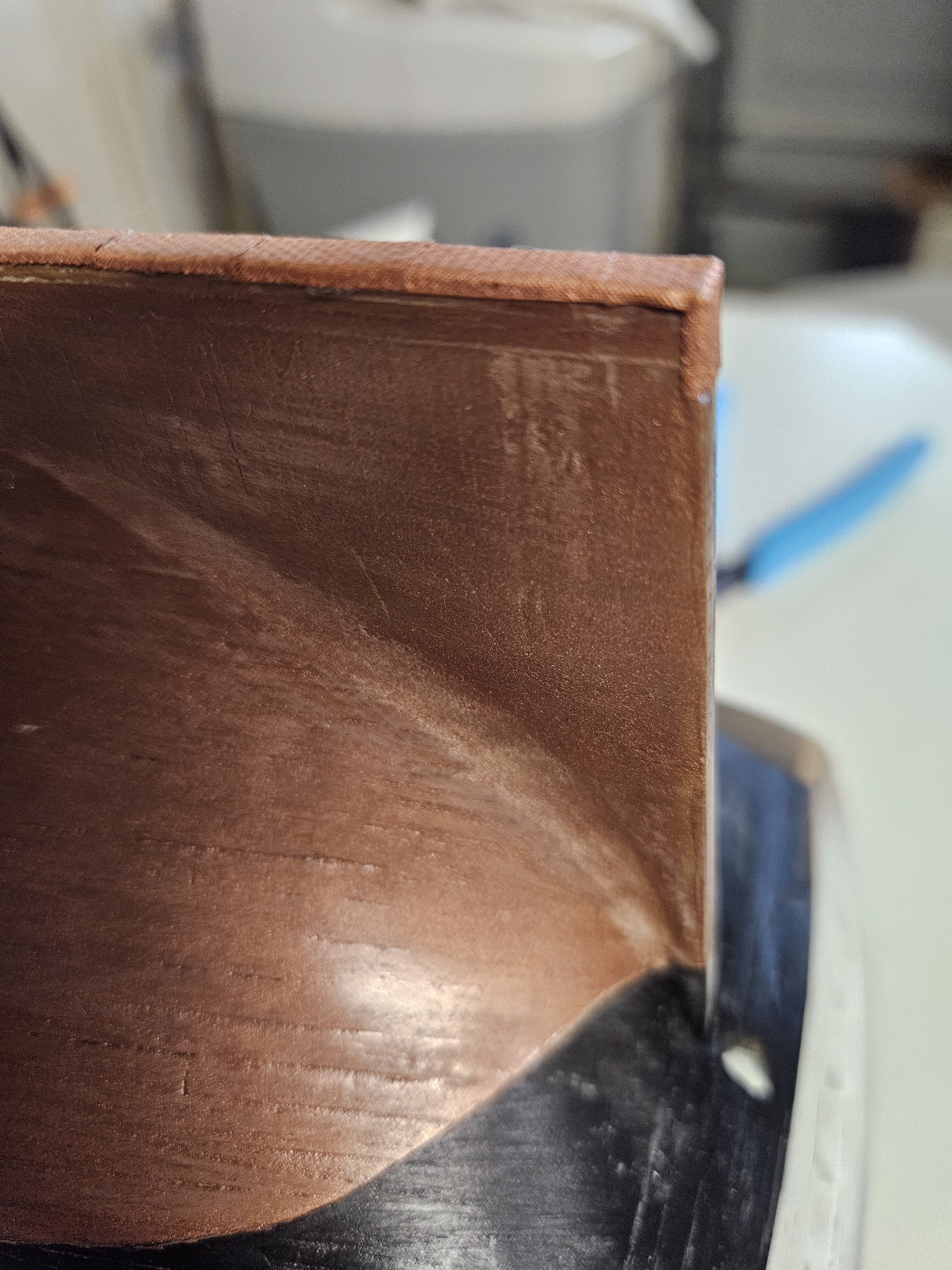
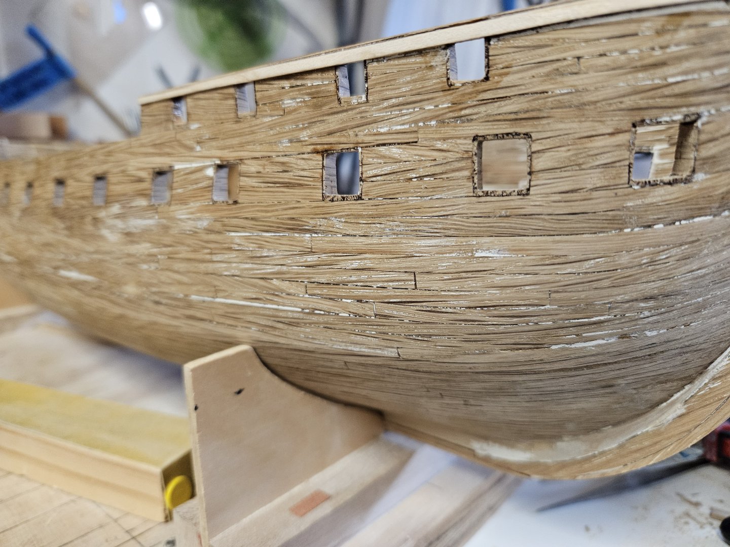
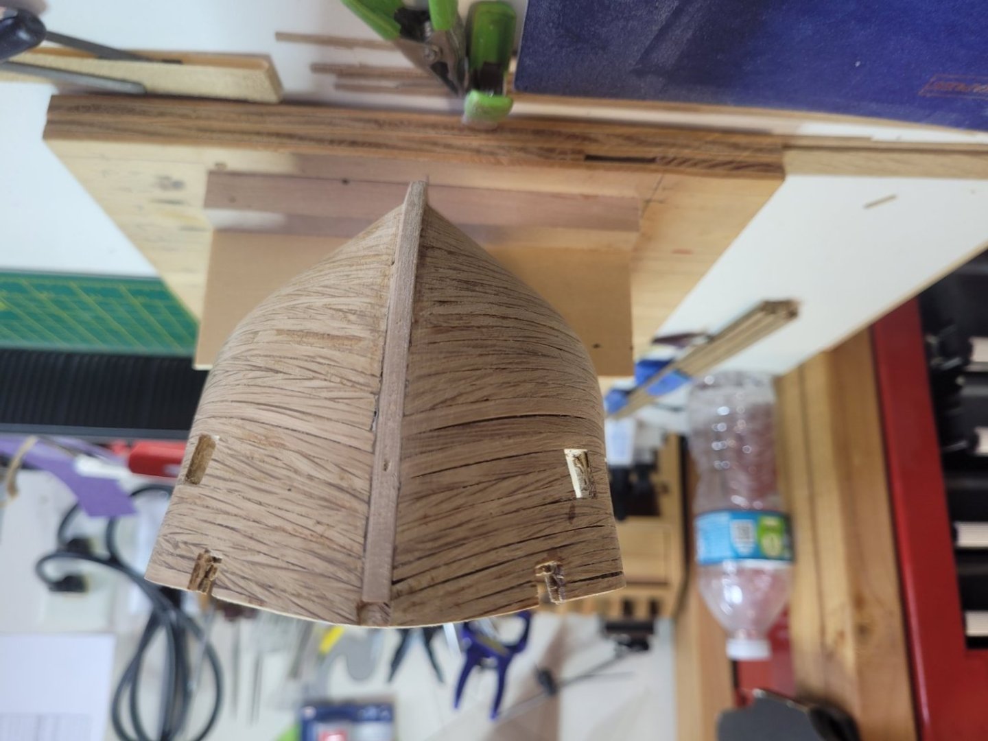
It has been awhile since I posted an update. The inner and outer hull is completely planked, the gunports are finished and I have started on the bow stem. Here are pics of the finished gunports. After completing the gunports, I pressed in between the planking a mixture of wood glue, water and fine saw dust and sanded back to smooth. After filled in the fine spaces with wood filler and then sanded smooth again. In the picture, you will notice the cap rail installed (just got a little ahead of myself there). Satisfied with the hull I then proceeded to the stem installation. This is where it became a little difficult. Using the template on 16 of the instruction book, I cut out the stem and knee, sanded the knee tapering from the stem to 1/8" at the leading edge of the knee. I then cut the slot for the bowsprit gammoning (which was not easy) and then installed the stem and knee as per the instructions. It fit perfectly, which led me to the conclusion, the 3D printed hull form came out dang close to the plan. The following day, after the glue dried (used wood glue to allow for minor adjustments before setting), to validate the knee and fit, I picked up in the instructions where it recommends to test fit the photoetched brass bow grating. It did not fit well at all. The edge of the grating against the hull needs to have a notch cut to fit around the stem. If I did not cut the notch, the grating would be too high covering the access ports. I cut a notch out of the grating edge that goes against the hull and then test fit again. What I noticed this time is the slope of the grating (will address this next). If you look at Figure 26, Section B, you will notice that the grating is on each side of the stem, not continuous line across the section. This indicates a notch is cut to fit around the stem. Additionally, from the USS CONSTITUTION website, this drawing also depicts a notch in the grating around the stem. Back to the slope of the grating, it was too great, almost to the point of being ridiculous. Looking at the knee and comparing to the profile drawings in the book, in Marquet's and the multitude of plans from the Navy, it was too high. If you look at Photo 9 on page 24 of the instruction book, you will notice that the knee is high. If you were to take a straight edge and place it on the cap rail at the forward rail where the hull is cut out on the spar deck and then place the straight edge on the rail at the bow, it will then intersect just at the notch behind the top of the knee. This is further reinforced by Figure 26 on page 48. Here is what I mean by a straight line from the railing to the notch in the aft of the knee. Also, I felt it necessary to test fit the britannia metal piece for the knee, and it fits perfectly. So, how much fore-aft slope is there in the grating? There, as far as I can find, no cross-sectional drawing that show this. Using the drawing from the museum, you will notice the slope by looking at the head against the gammoning. Using that drawing, I estimate the slope to be approximately 11 - 12 degrees. Next steps, painting of the hull, inside and out. After that is completed, I am going to jump a little ahead (again) and copper the underwater hull. With the significant number of plates to adhere to the hull, that should take a good while. Cheers, Brian


-
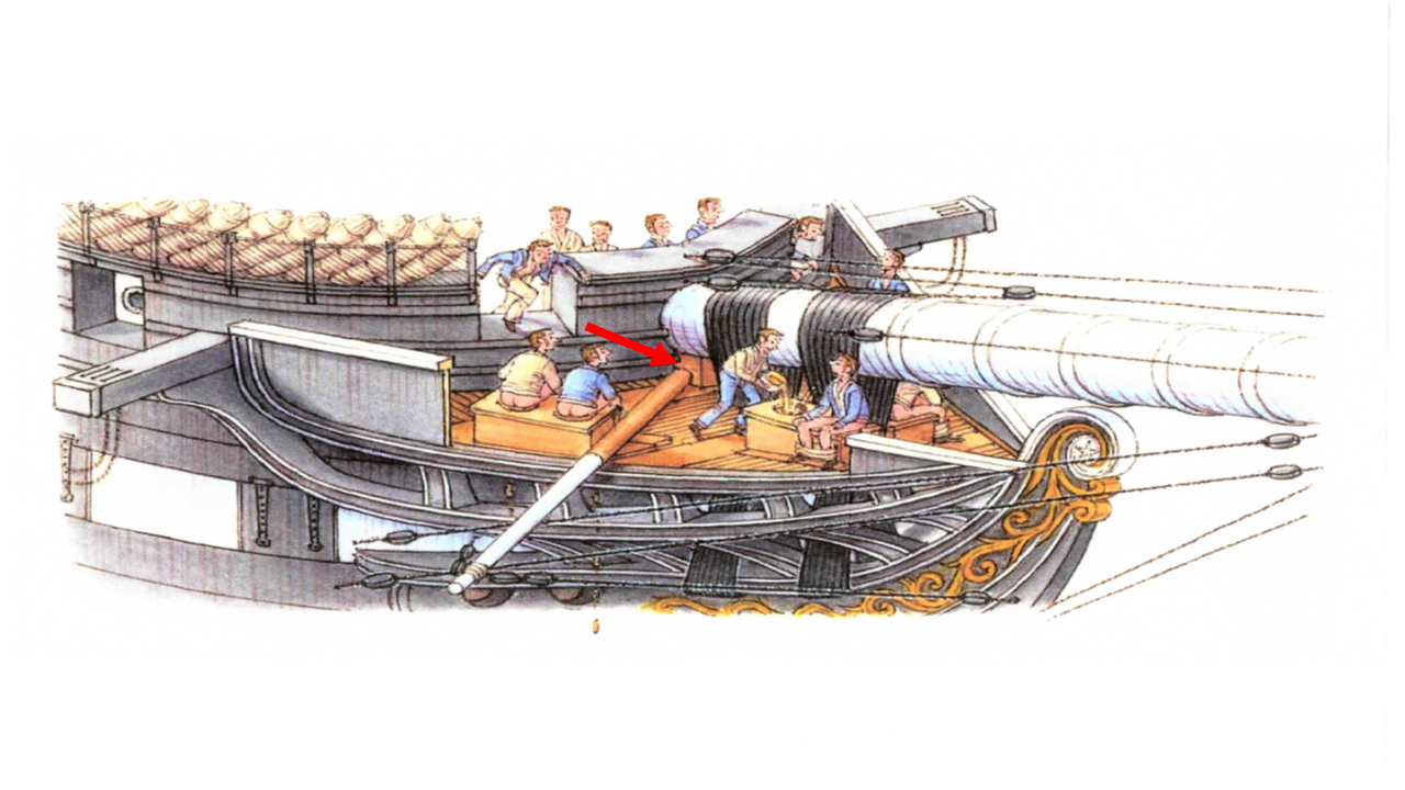
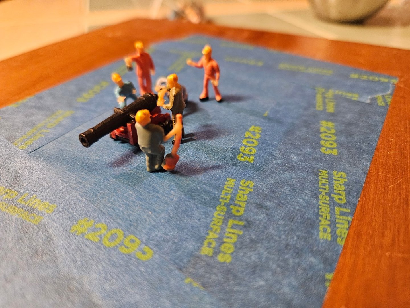
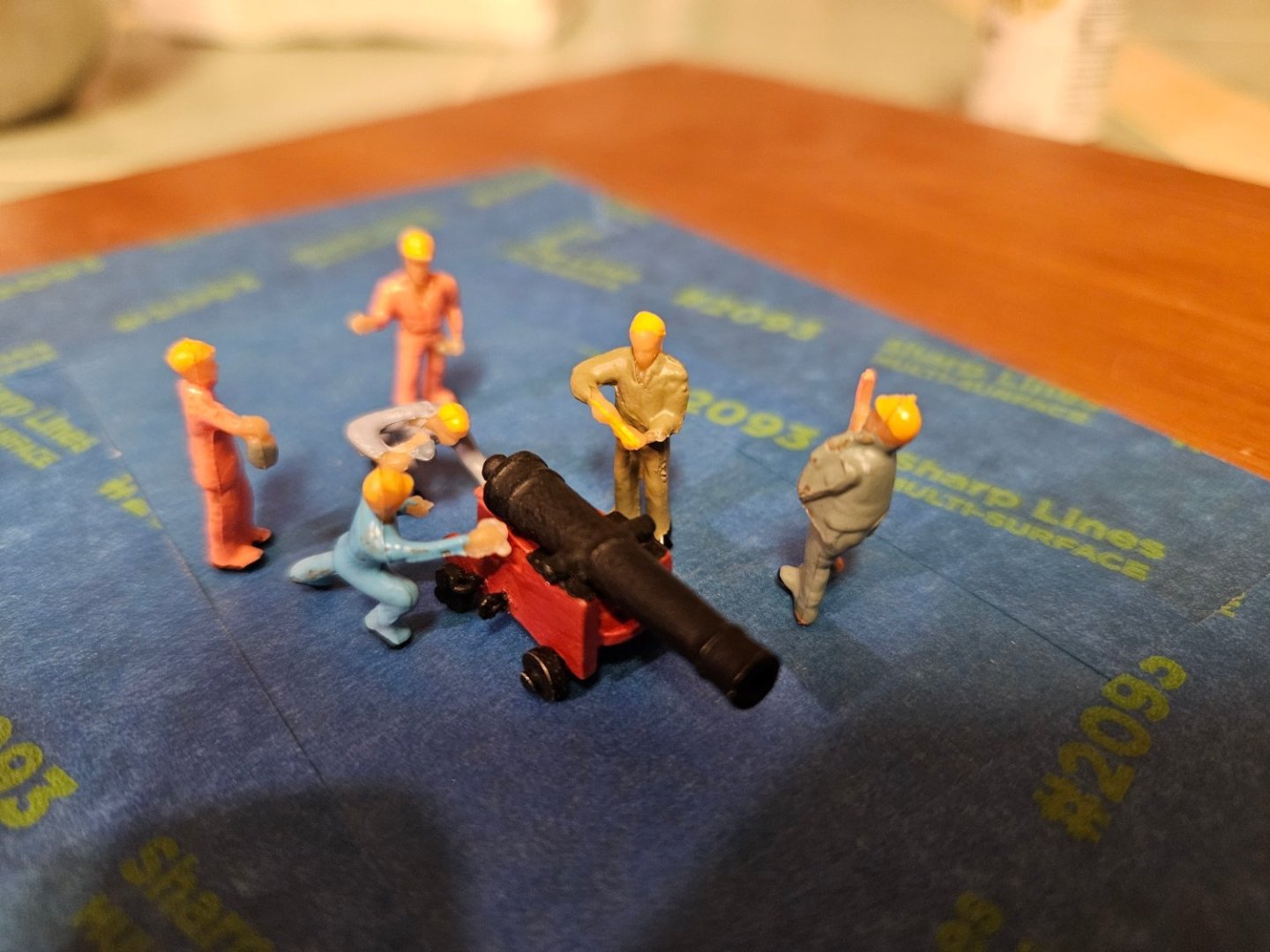
@g8rfan Thanks for posting this link. I too have been searching for figurines to add to my build and have not had much luck. Even tried 3D printing, and that failed. I did purchase one packet and positioned them around one cannon to see if they would work. And they are perfect - yes, I will have to repaint them since orange coveralls and hardhats were not in vogue in 1812, but their positions and shape are perfect.
-
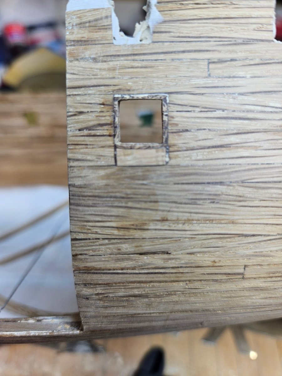
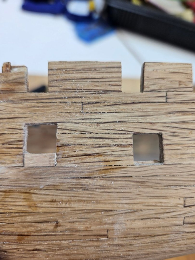
So....scratch all that I posted on on December 17th. It is not working out as I had envisioned. After checking the size of the gun port lids (.36" square) and looking at another Constitution build log, I changed course and lined the sill, header and sides with .02" planks. This finished off the port and gave me acceptable corners. Here is the finished port for the first one.

-
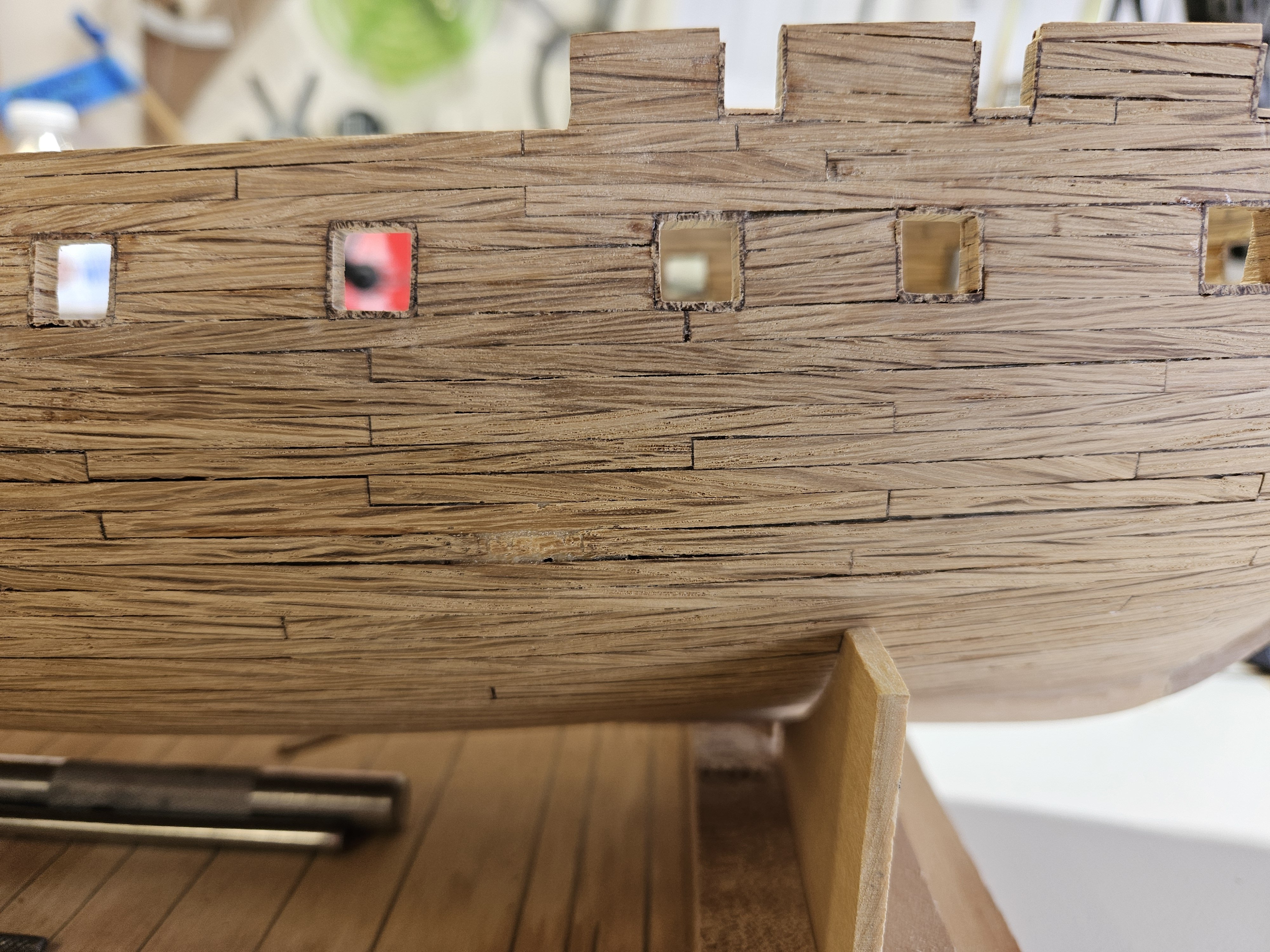
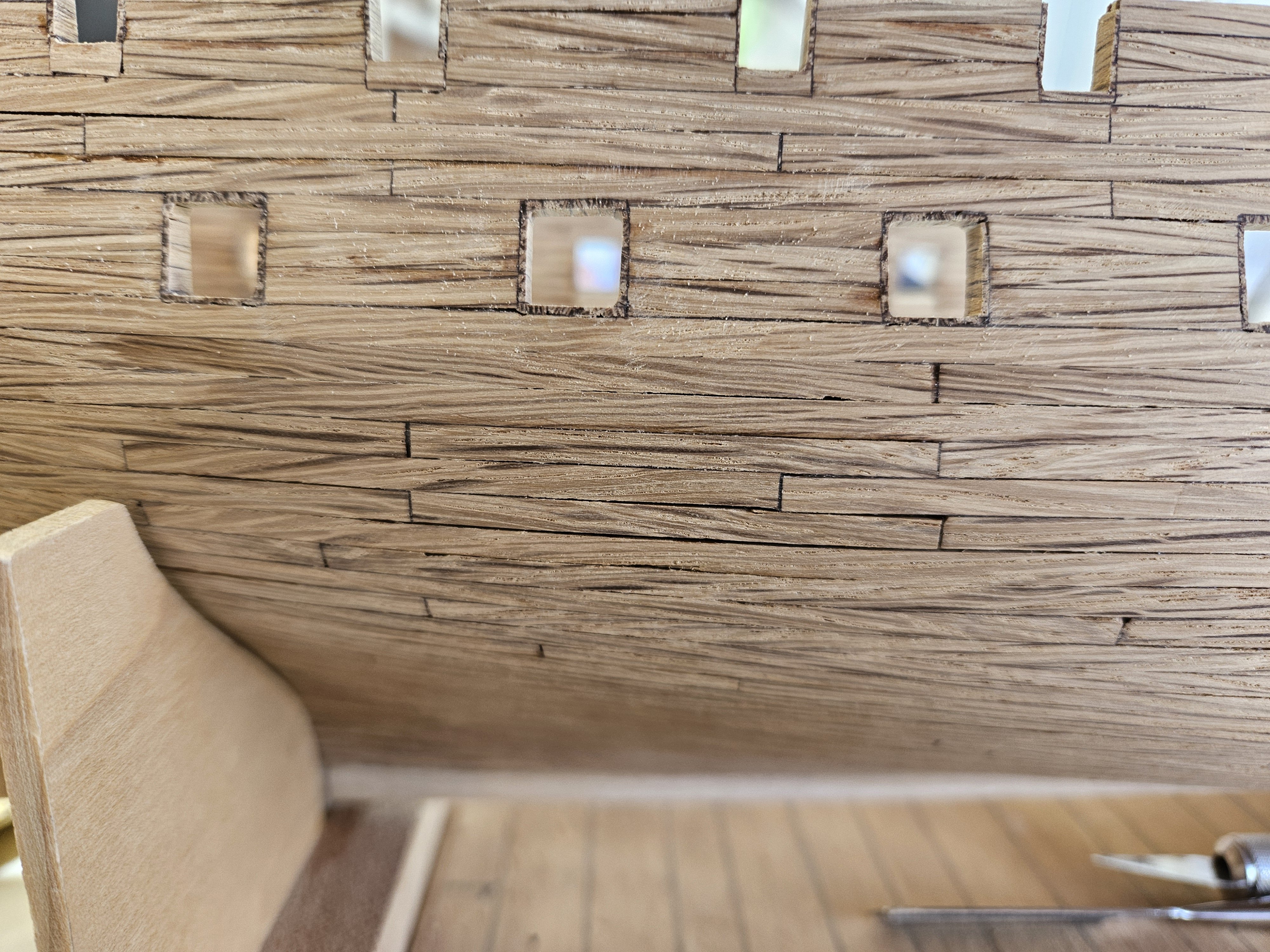
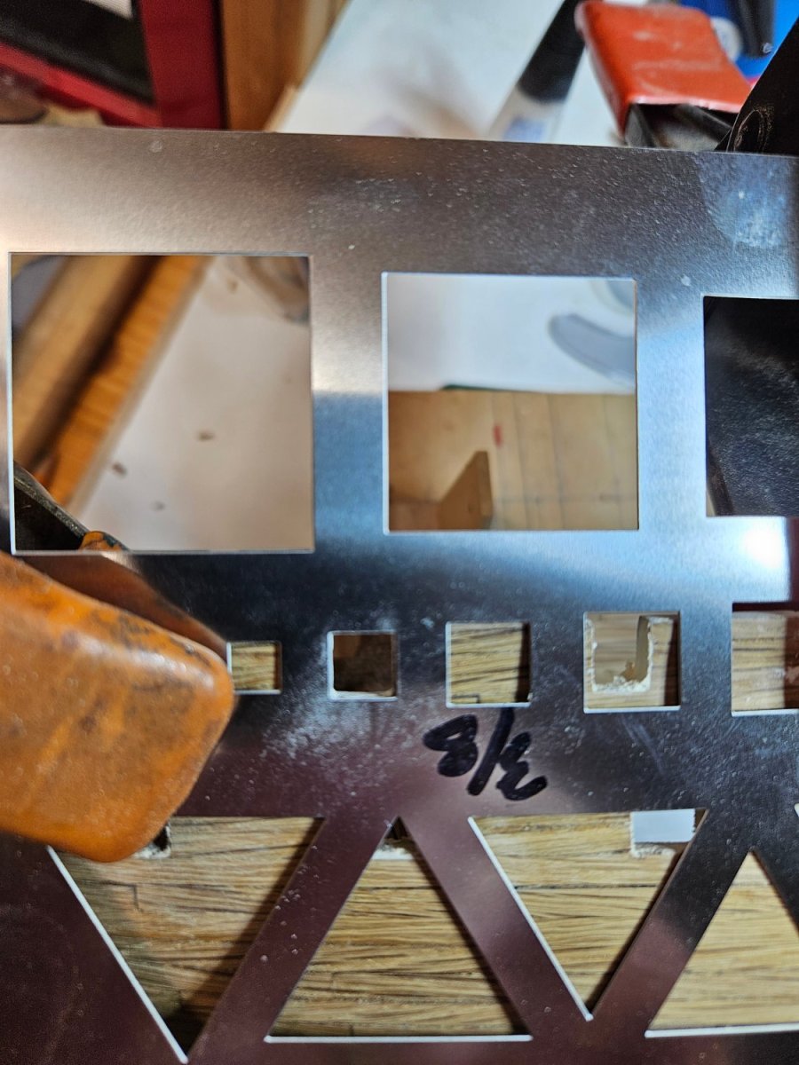
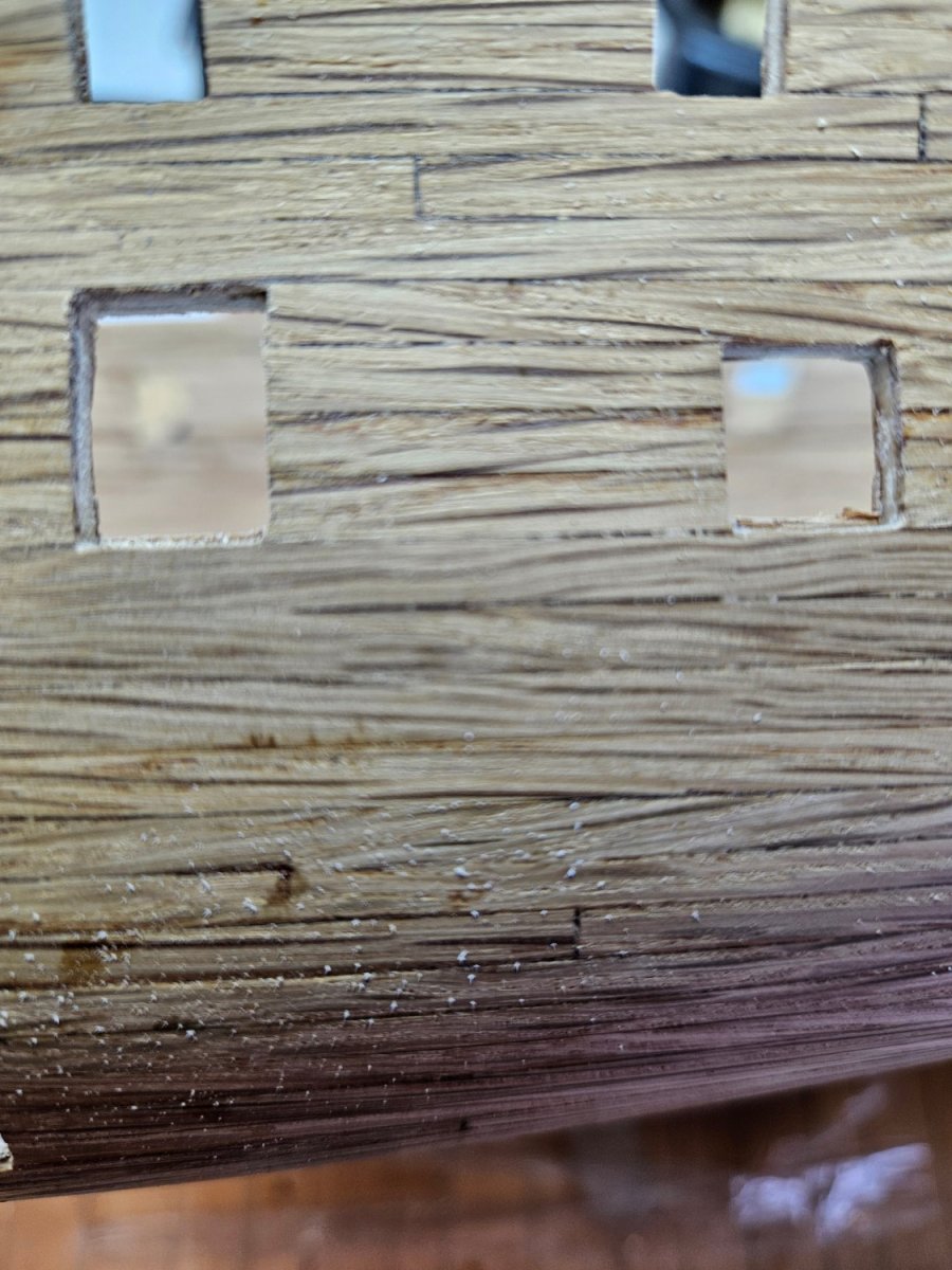
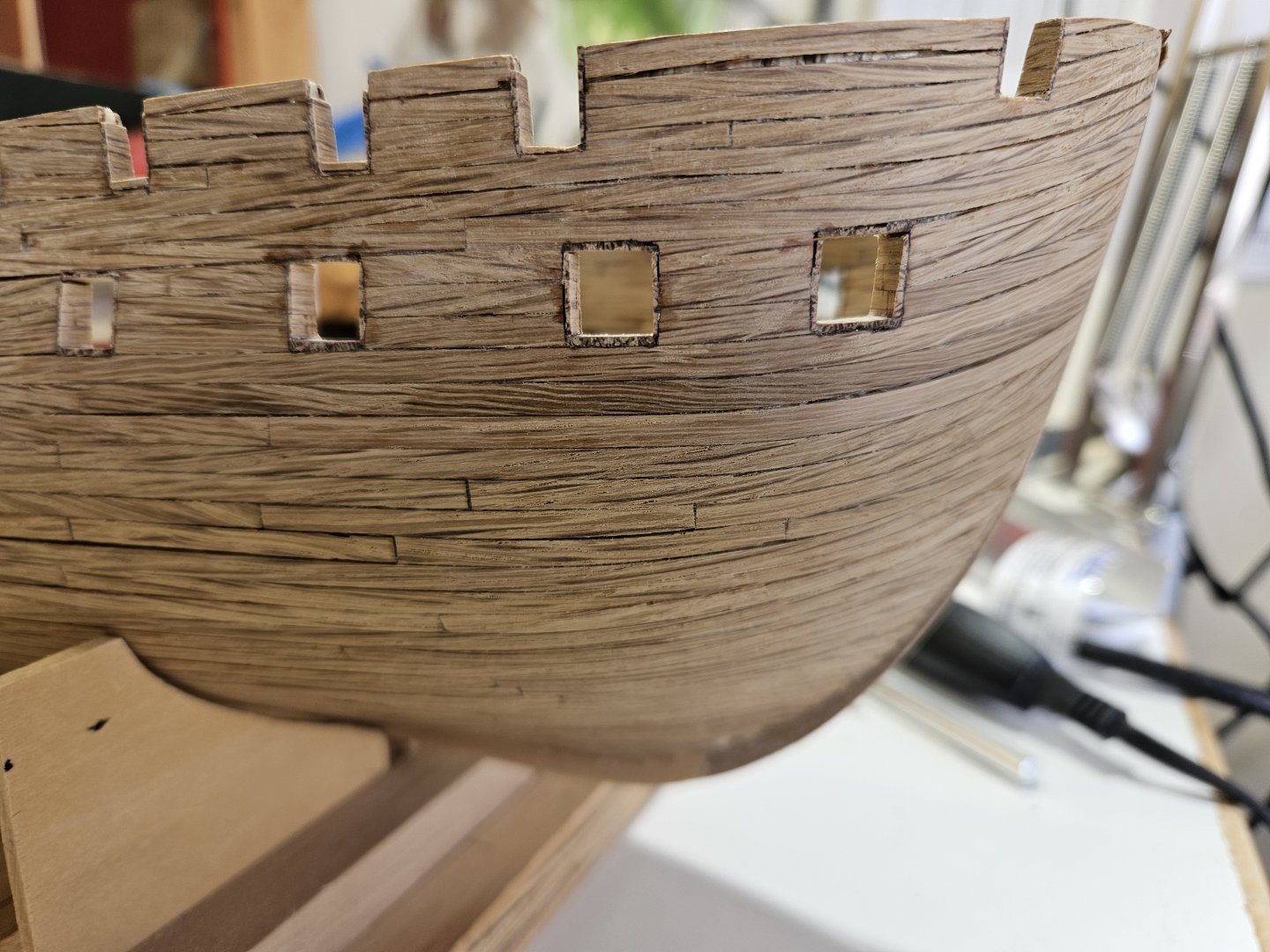
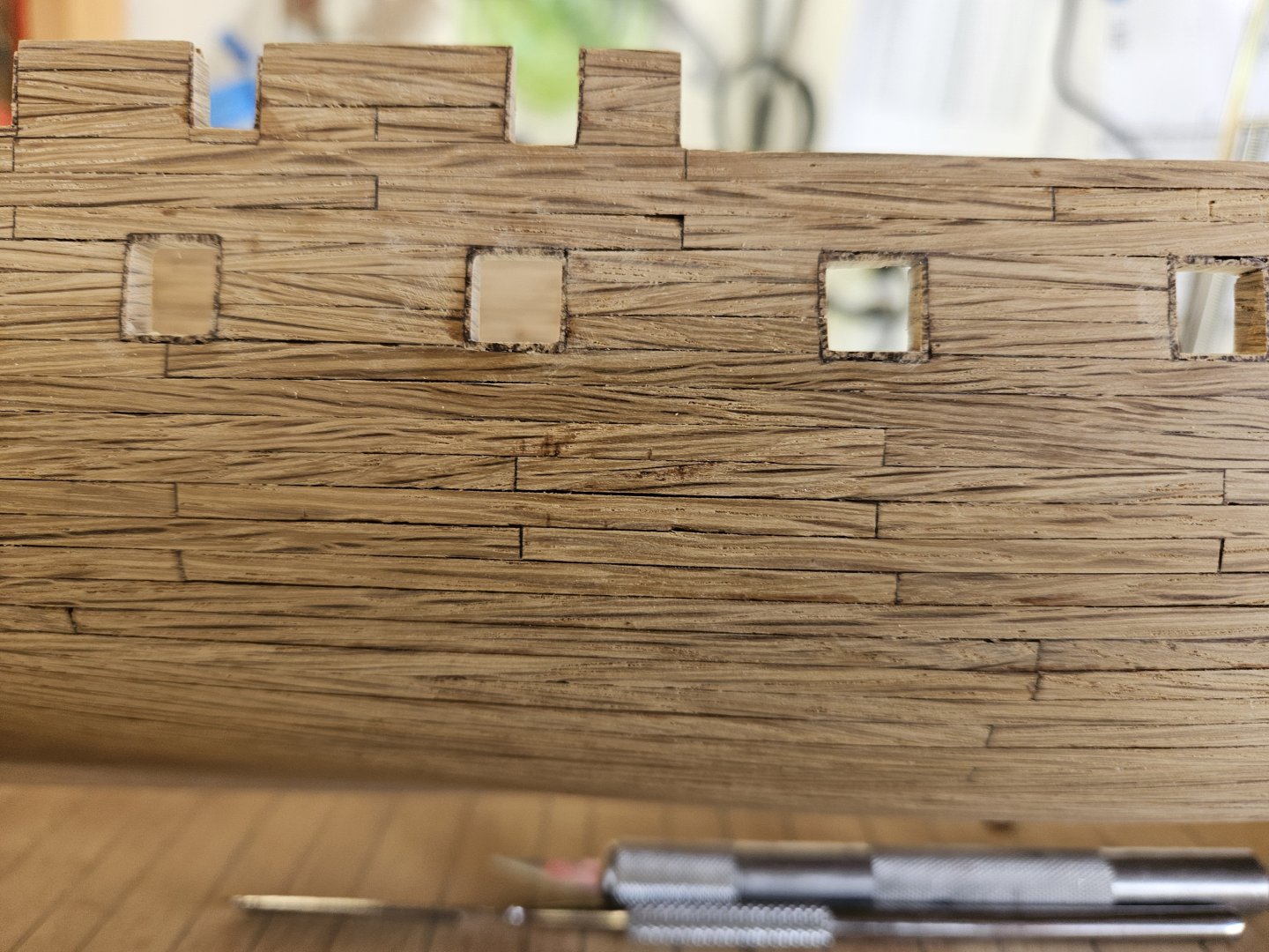
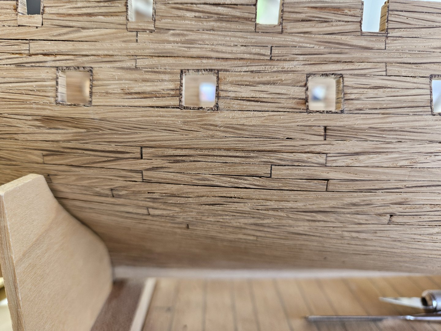
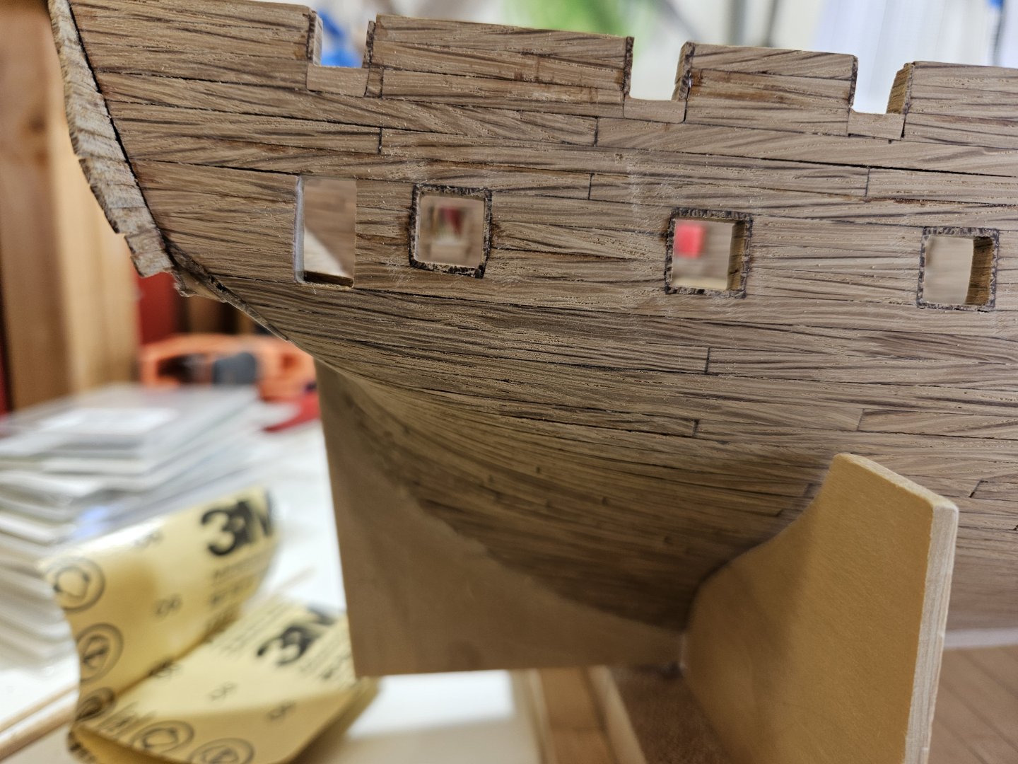
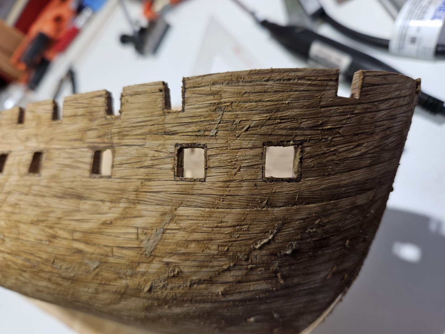
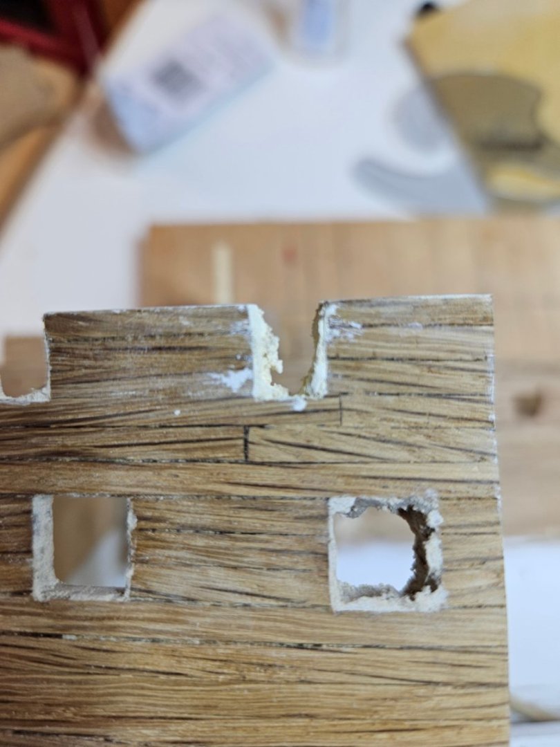
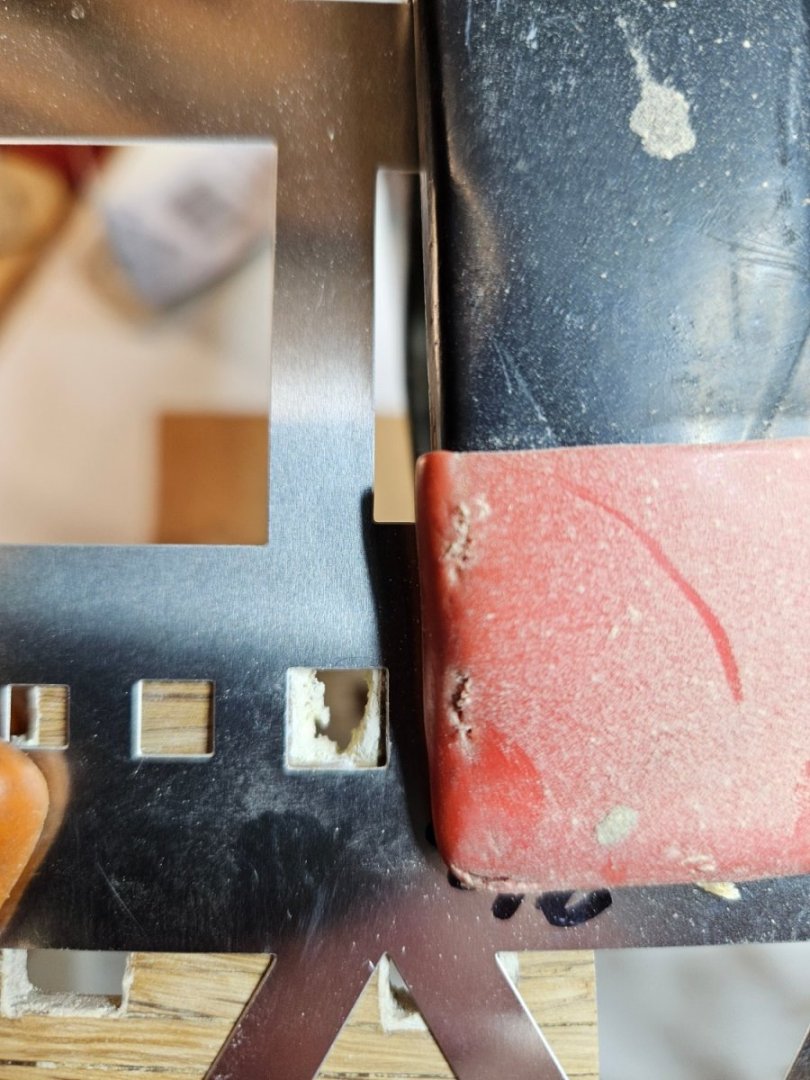
My next challenge after "raising" the gun ports was to square off all gun ports. Those on the gun and spar deck. The openings on the spar deck had a tendency to flare outward at the top of the gun port, and those on the gun deck had rounded corners and, if I tried to square the corner, it would round the side since I would put too much pressure toward forming the corner. I knew that I needed to fill in the sides of the gun ports with plastic wood and sand them down square. But, without a metal template, I would just be repeating what I already have. I did find a metal template that has a 3/8" x 3/8" square and a 5/16" x 5/16" square (through Amazon) which would work perfectly to help square off the ports. Using 80 grit adhesive backed sand paper strip attached to a mini-file, I would sand the side of the gun port until the sandpaper scraped the metal template. I would then increase the grit to 220 and do the same, sanded until it scraped the metal template. To form the corners, I used a triangle shaped file so I would not have to use extra pressure to get the file into the corner. There are some minor touch-ups needed, but the shape is real close to being square.

-
Thanks Jon. Yes, it took me a couple of weeks to come to this solution. Just had to purchase some very fine tooth "keyhole" saw blades to accomplish. As for the wood, it is white oak. I am cutting, planning, and sanding each piece from stock white oak 6"x1" boards. Yes, a lot of waste in the process, but that is what I do best...turn perfectly good pieces of lumber into saw dust 😀. I will be painting as per the specs in the kit and will also copper plate the underwater hull.
-
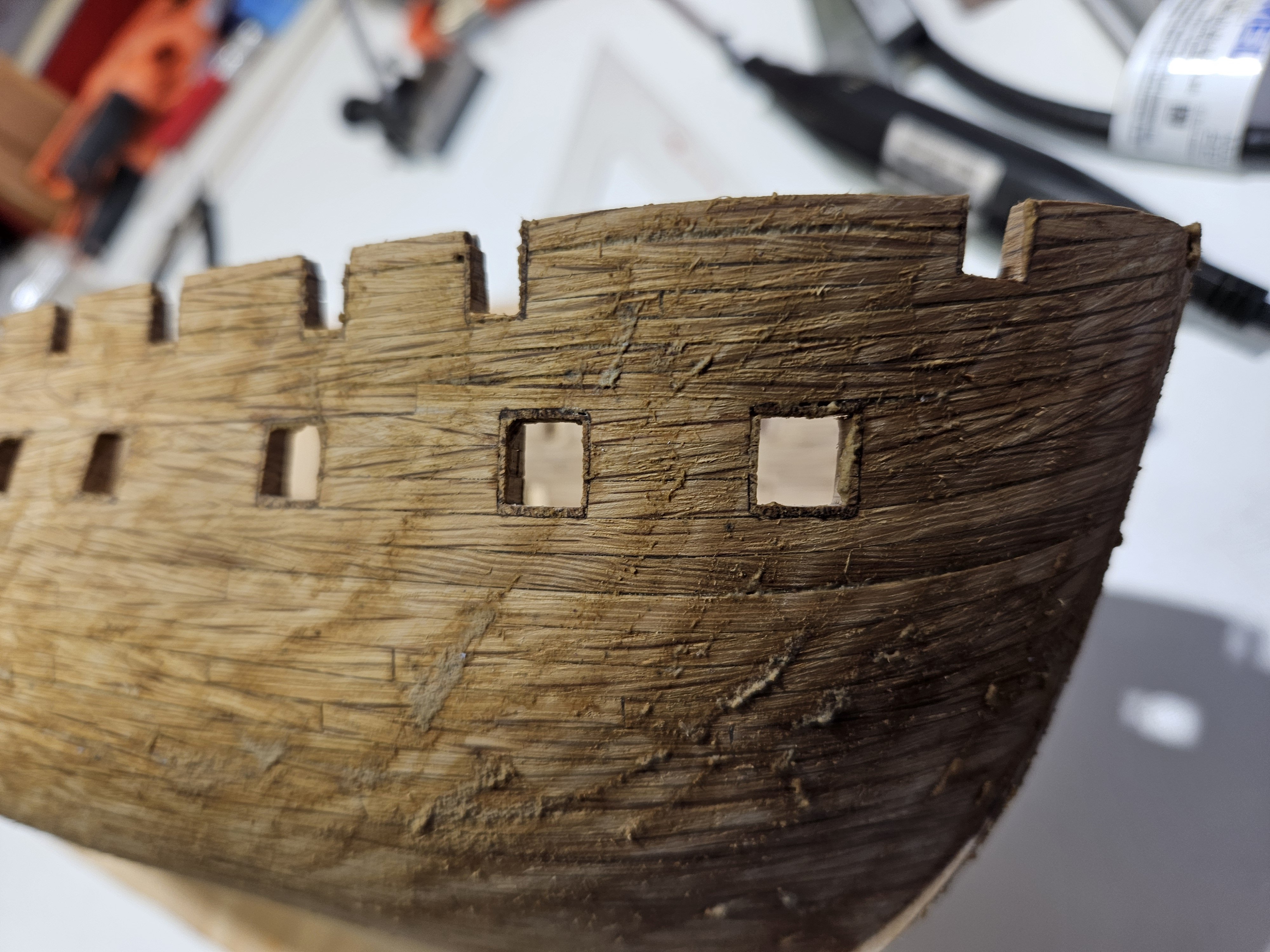
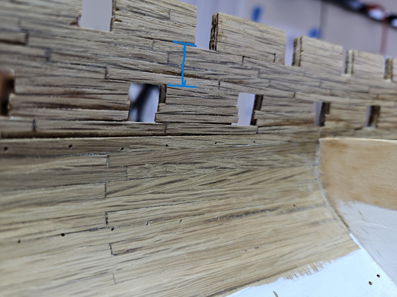
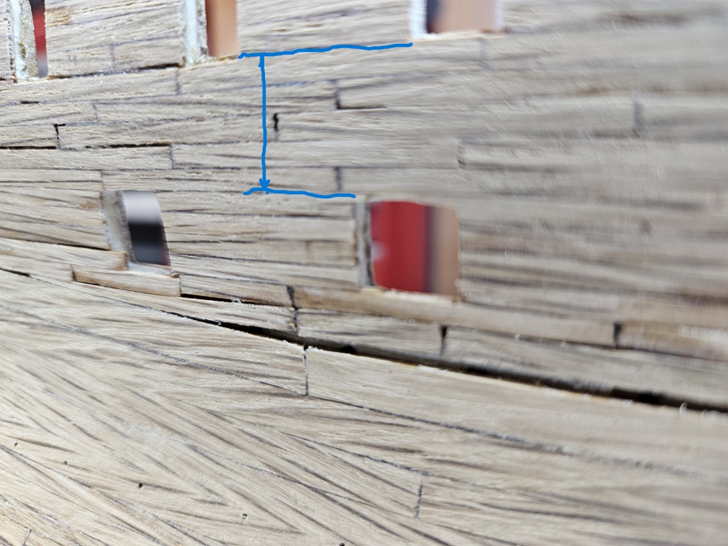
I have for the most part completed the interior planking. Upon inspection I noticed that on the port side, the gun deck gun ports were 1/8" lower than the starboard gun ports. That would be a foot which is significant difference. First picture is the starboard side, the other, port. The port side has 5 planks from the bottom of the spar deck gun ports to the top of the gun deck gun ports. The starboard has 4. Thankfully this was only limited to the gun ports on the aft section of the port side, 7 of them. My dilemma was how can I move them up and would it look good. Taking a deep breath, I cut a 1/8" section out of the top and sanded. Then, I glued a 1/8" piece of oak to the bottom and sanded that smooth with the interior and exterior hull and the bottom of the gun port. There, the gun port is now moved up the side by a foot, or 1/8". Now to do the other 6...


-
Avi, my only recommendation would be to do all you can to ensure the corners are pressed down. I too have given it thought on how to achieve a "smooth" surface with the platting and feel that pressing using a mini-roller would be my best option. Here is what I am referring to https://www.crutchfield.com/S-nanjTCMS645/p_15410005/Dynamat-10005-Roller.html?XVINQ=GZ0&XVVer=23B&awcr=628226750370&awdv=c&awnw=g&awug=9011556&awkw=pla-338049137464&awmt=&awat=pla&gad_source=1&gclid=CjwKCAiAmsurBhBvEiwA6e-WPCWYGGJauK5mjhW1Q49RQkdvHo2oMrQxcw7LQwMYGI3-J_hrBvPk9RoCTQQQAvD_BwE With a slight bit of pressure, you should be able to get the corners pressed down. Brian
-
It has been a slow go this past year. When I last reported, I was preparing to commence the exterior planking. I have finished the exterior, and started on finishing the interior. Since I am electing to use Live Oak as the planking material it does take time. I have 12" long pieces of 1"x 8" pieces of Live Oak stock that I have to rip with a table saw, then plane it down to 1/8" using a table planer, then using Micro-Mark drum sander/planer, down to .09". There is a lot of waste, but I don't have any other means to get the planks out of the wood stock. From there, using a band saw, I cut the planks (.04"). Through the sanding process, I sand off about .01" to get the correct thickness. Here are the pics. As you can see, I have already started on the interior, working from the top to where I left off from the keel up. I apologize in advance, I have no clue why the bow and stern picture are upside down. I have tried multiple times to get it right, but just not cooperating.... Cheers, Brian


-
Avi, I have no recommendation with regards to coppering as I have not gotten to that point yet. But, I do appreciate you asking the question and @MrBlueJacket (Nic's) response. On to your initial question regarding the planking creeping up into the gunport or sagging down into. I just started the interior planking, so again, thanks for the insight. If I were to face this dilemma, I would trim (sand) the plank sagging down into the gunport and fill in at the bottom. My thinking is that once complete, it will be very difficult to view the planks at the top since the spar deck will be hiding that from view for the most part. And filling in at the bottom still leaves you with the option of sanding it down so that the gun is properly centered when run out. I do like the idea of building a mock gun. With that it would give you and idea if you need to fill in or trim the planking at the top or bottom instead of guessing. Brian
-
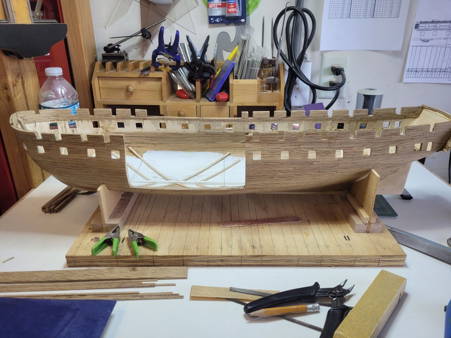
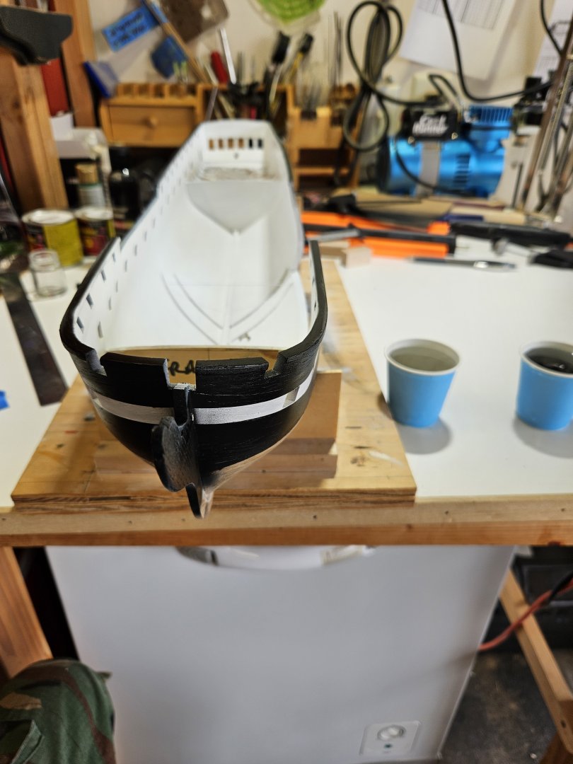
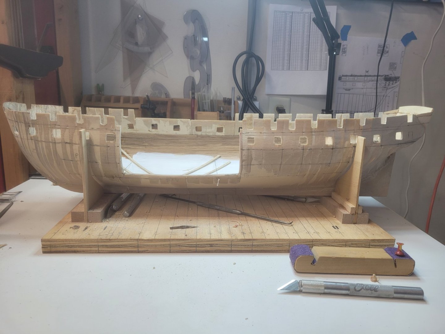
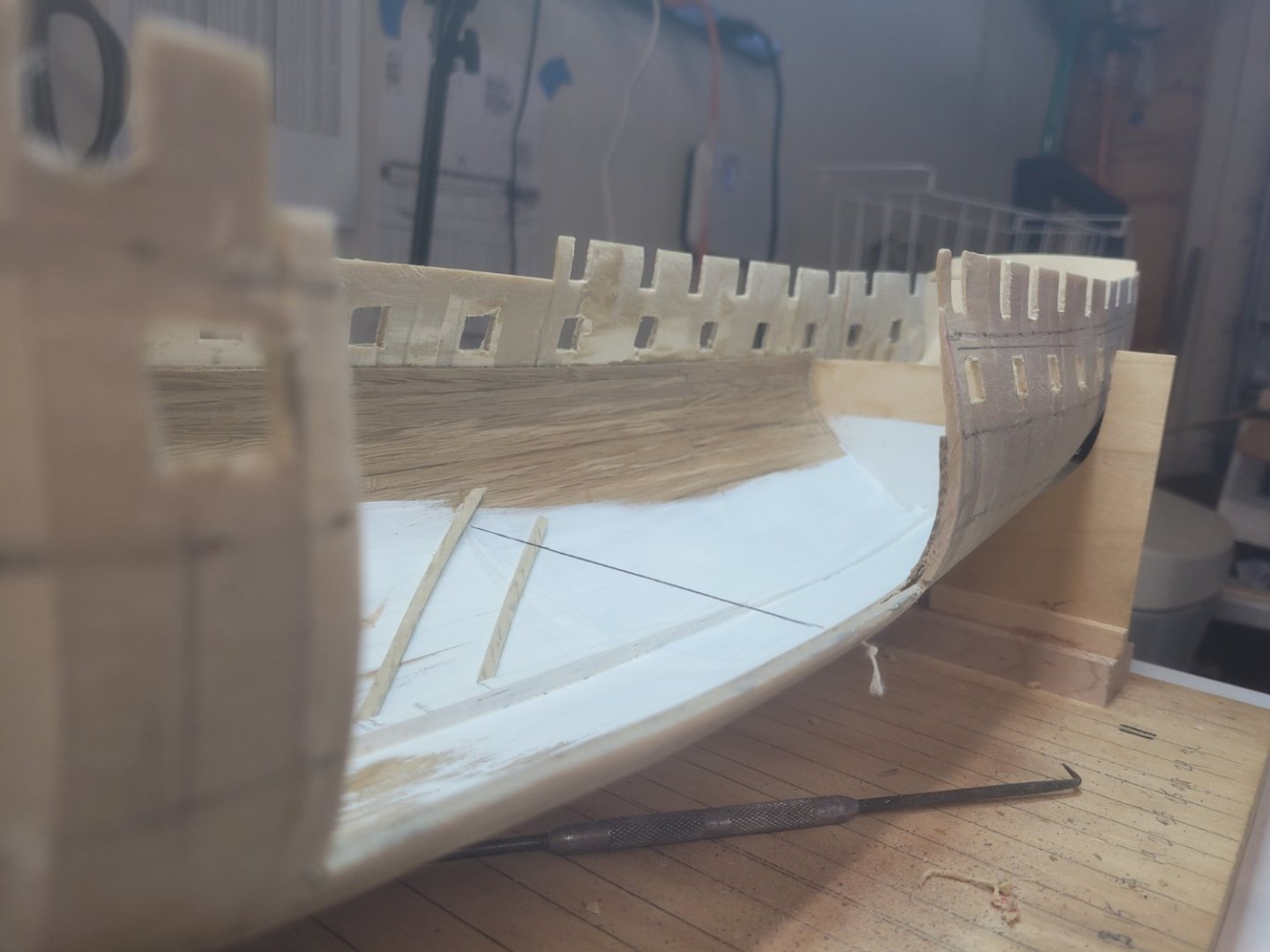
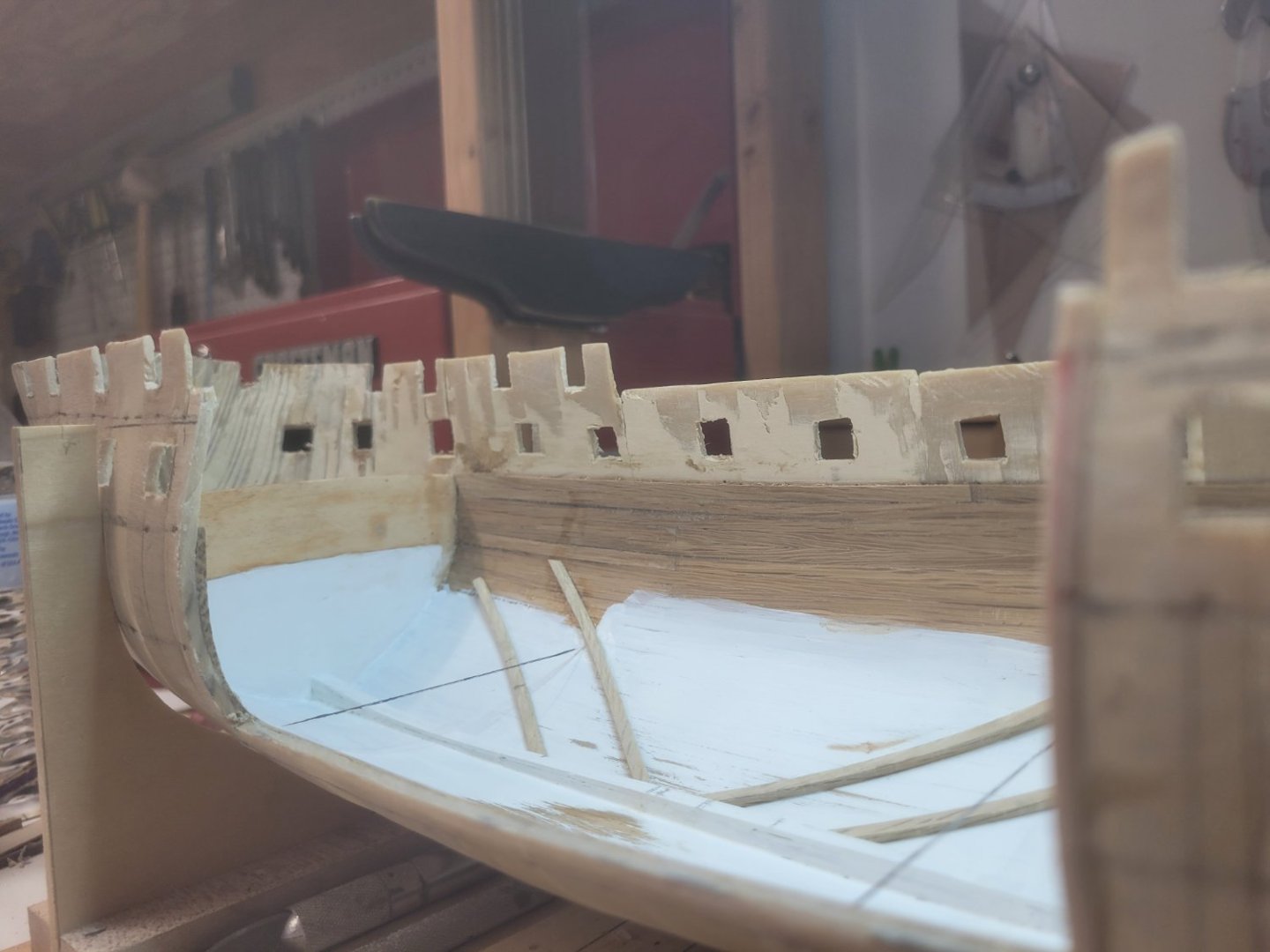
@Mort , those are my thoughts as well. just have to avoid the bright blue and pink gravel 😀 So took a huge step yesterday with the plan of being able to view all decks inside the ship. I cut out the section from the port side. It went easier than the gun ports. Used a Dremel saw to cut through the hull shell and interior planking. Above is a straight on view, below are looking aft and forward to give you an idea of what will be visible.
-
The gun ports have been cut. I will have to say, very nerve racking to go through that. To cut the ports I used two methods. The first was with a high speed drill using a 1/64 drill bit. I would make multiple passes as if I were drawing a line with the tip of the drill bit. The second method I used a hot knife with a 3/8in flat blade. It cut through easily, but left behind melted plastic which I did have to cut either with a knife saw or an exacto knife. Of the two methods, I would recommend using the hot knife. It was not without its problems, but comparing the results from the two, the hot knife was better. I have still to cut out the passageway for the quarter galleys and the port side for interior viewing, and mark the decks on the inside of the hull. Once those are complete, I foresee starting the exterior planking.
-
With regards to your airports & scuppers question, yes, I too believe those pieces you pictured are the airports. I have attached the plans for them if you do not have. 25001a_Airports & Scuppers.pdf
-
So, back to the topic regarding pig iron vs. stone ballast. Did a little more research and according to the USS CONSTITUTION Museum during 1812 the CONSTITUTION used pig iron as ballast but also gravel in the hold for the casks to rest on. With this, I will forego the pig iron and just add gravel to the hold before putting in the casks. Now to find 1/96 scale gravel...
-
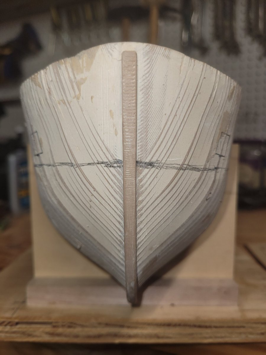
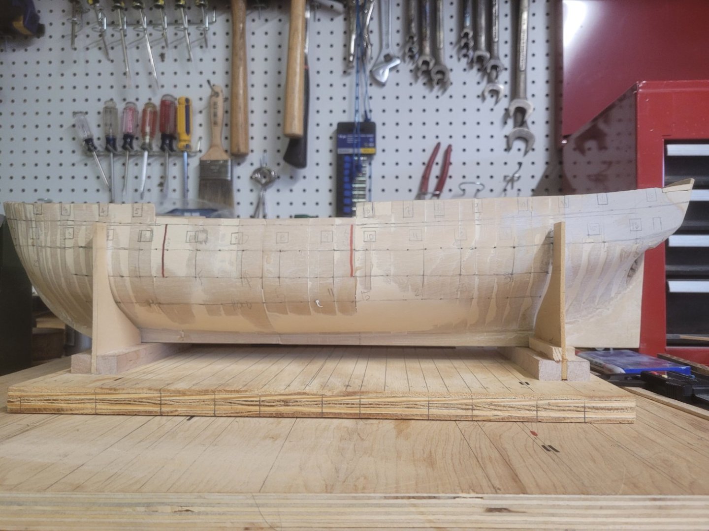
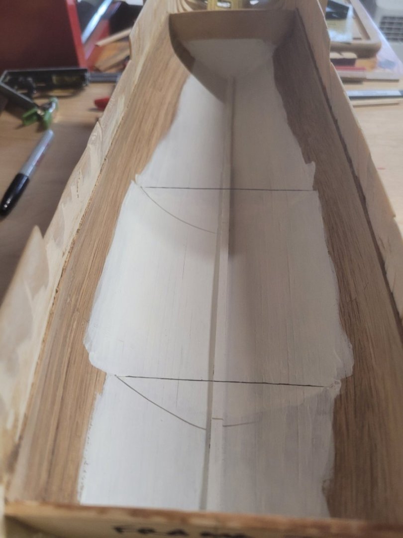
I felt that I was ready to commence the exterior planking, but, I was wrong. I needed to transfer the gun ports from the 2D drawings onto the hull shell. Additionally, I wanted to mark the deck levels along the hull. This will aid me in the construction of the interior decks. Using the Waterline Marker as previously discussed, I marked out each gun ports lower left corner and using a draftsman's template, I outlined each gun port on the gun deck and spar deck. I found using the template as recommended in the Bluejacket instructions made this process very simple. Here is the port side. The red vertical lines are where I intend on cutting the hull out to see inside the ship. I have not yet decided where the cut out will be for the Orlop Deck. I know that it will include the main hold and aft. But how far aft, not sure yet. So, my next move was to define the main hold on the inside of the ship. I marked the after line of the forward section of the Orlop deck and the forward line of the after section. I drilled a very small hole horizontally through the hull at those location on both port and starboard side. I ran a piece of small stuff through one hole to the other and super glued them in place. Below is a picture of the string through the hull (looking aft). As you can see I also painted the hold areas in preparation of installing the Orlop deck beams. I was already to proceed with that process when I had one of those duh moments. I forgot to install the diagonal riders. So, I need to sand down the paint to bare wood and then install the riders. Now a questions for the group. Constitution's ballast in 1812 - granite stones/boulders or pig iron? I am leaning towards pig iron. Here is why. In my research the initial ballast was pig iron and this was replace in 1813 with granite stones/boulders during a shipyard period. The battles with HMS Guerriere and HMS Java occurred in 1812, before the change and, during the battle with Guerriere is where Constitution earned her motto "Old Ironsides". So, 1812 is the year I am going for. However, I have seen a number of Constitution hull cross section models and they all have granite stones/boulders as ballast. So, I am leaning toward pig iron, but have my doubts.
-
Thank you for the bow on view. I am struggling with wrapping my mind around the tapering of the planks as they approach the bow. It looks as if you did a very fine job with that. The planks meet perfectly at the bow from port and starboard, and have a slight up sweep. To me, it looks great and sure once you sand and paint, you will be pleased with the work.
-
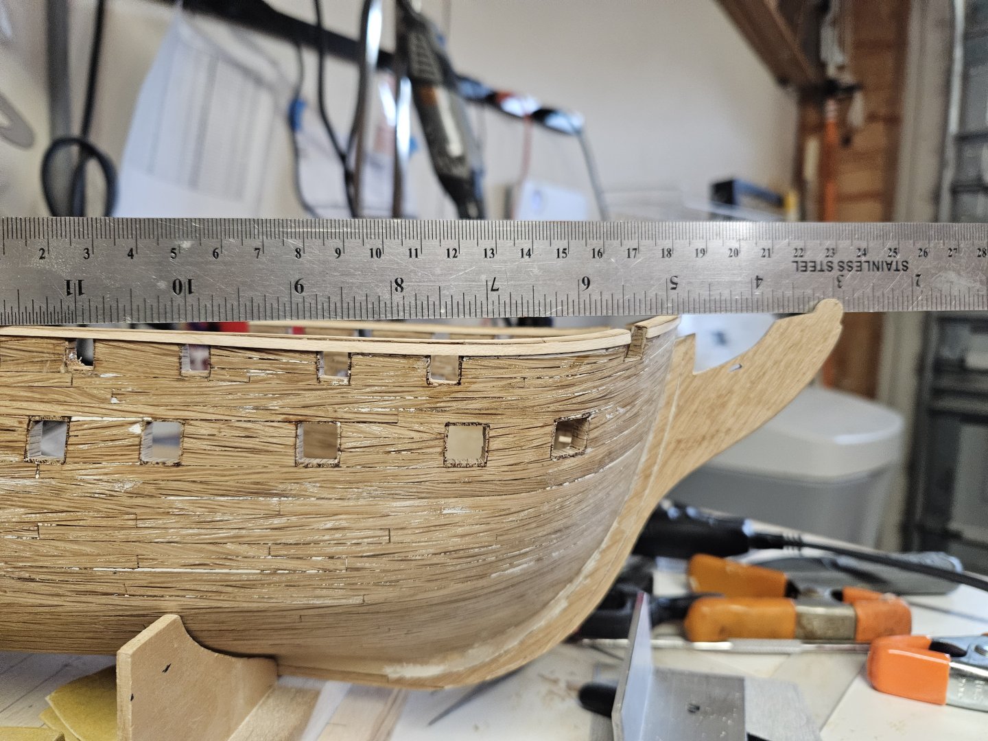
Thanks Jon. With the dimensions from the drawings you provided and me stepping away from the problem for a day, I am sure that I have it figured out. The measurement from the deck to the bottom of the gun port is actually from the top of the deck beams, not the top of the finished deck. Subtracting the height of the gun barrel (.38) from the height of the center of the gun port (.4375) yields .0575. Converting that to 1/8in scale is roughly 5-3/4in, which is roughly (close enough) the thickness of the deck planking. I should be good to cut the gun ports now. Thanks.
-
I am basically now at Section 7 of the instruction book. I have marked, from fore to aft the gun deck on the outer hull. Additionally, I have marked each gun port on the gun deck. I did not attach the stem, false keel or rudder (the sternpost is part of the 3D printed hull). I have elected to hold off attaching those until after cutting the gun ports on the gun and spar deck, and the passageway into the P/S quarter galleys. Marking the gun ports and deck line from the 2D drawing in the instructions is made very simple using Micro-Marks Toolmakers Surface Gauge - Ship Waterline Marker. First step was to transfer the frame from the working baseboard onto the hull. Using two builder squares, this was a simple process. One square was standing upright, and the other lying flat on the baseboard. The flat square was place at the frame line, the second square then butted up against the hull and the flat square, then with a pencil mark the frame on the hull. I did this for all the frames, port and starboard. To transfer the deck line from the drawing to the hull, at each frame on the drawing, I measured from the keel to the deck line. Adjusting the Waterline Marker to the proper height, I then, at the same frame already marked on the hull, marked the gun deck line. Doing this on both port and starboard. After completing the marks, I free handed the deck from frame to frame. Next was the gun ports. I started from the most forward gun port and moved aft. I located the forward lower corner of the gun port and using the Waterline Marker, marked that corner on the hull. Once I had the corner, using a draftsman's template as recommended in the instructions, I drew the 3/8in square. This was done for all gun deck ports on both sides of the ship. As you can see in the pictures there was some adjustments necessary. The first go-around I did not get them in the correct location. Now I have a question. I measured the height of the gun above the deck (.38in) and the gun ports height above the gun deck. The bottom of the gun port is .25in above the gun deck. The center of the gun port is .4375in above the gun deck. This puts the gun in the lower half of the gun port. My plan is to have all guns run out, ready for battle. I envisioned the gun would be centered through the gun port. Are my calculations wrong? Or, is that correct, the gun is in the lower half of the gun port? I am hoping someone can shed some light on this as I am holding off cutting the gun ports until this is resolved. Thanks, Brian