Brian Falke
Members-
Posts
100 -
Joined
-
Last visited
Content Type
Profiles
Forums
Gallery
Events
Everything posted by Brian Falke
-
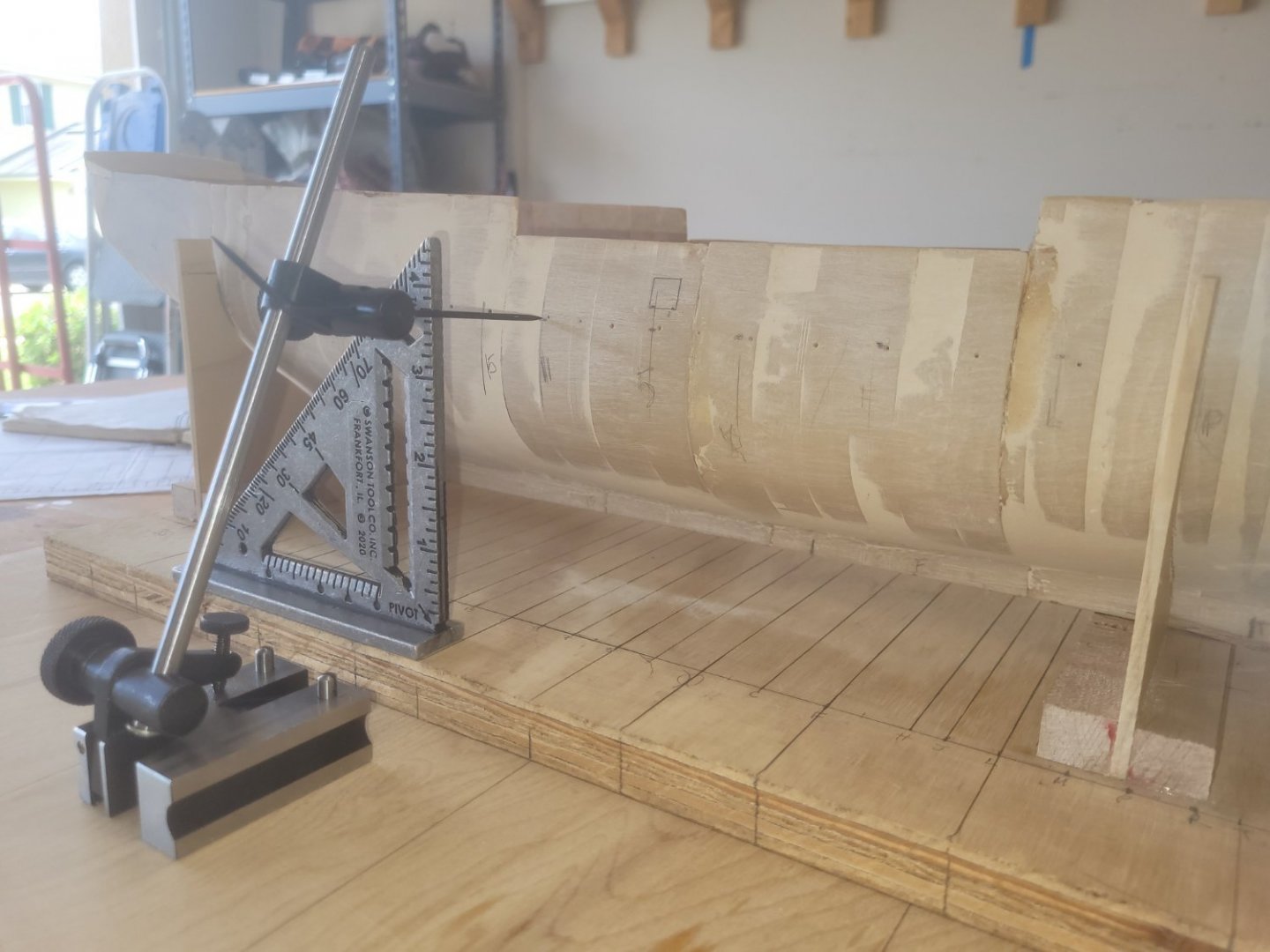
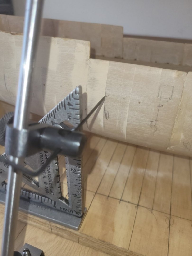
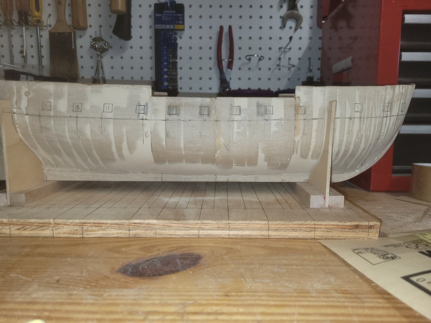
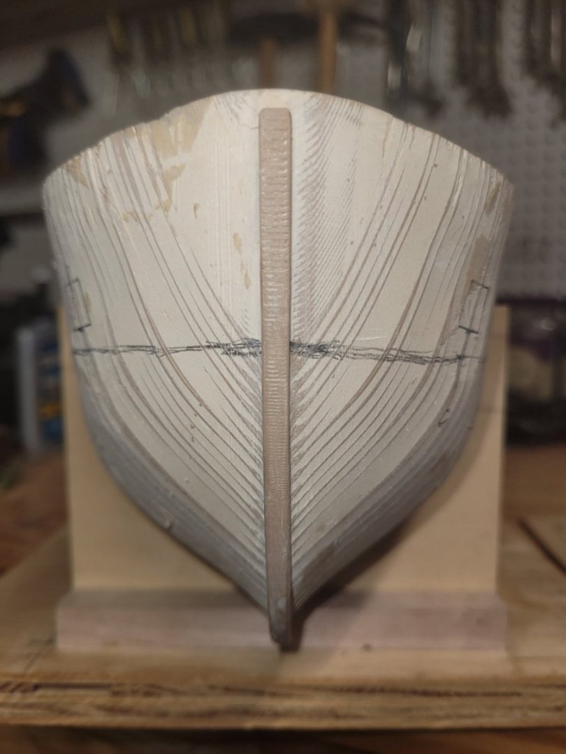
I am basically now at Section 7 of the instruction book. I have marked, from fore to aft the gun deck on the outer hull. Additionally, I have marked each gun port on the gun deck. I did not attach the stem, false keel or rudder (the sternpost is part of the 3D printed hull). I have elected to hold off attaching those until after cutting the gun ports on the gun and spar deck, and the passageway into the P/S quarter galleys. Marking the gun ports and deck line from the 2D drawing in the instructions is made very simple using Micro-Marks Toolmakers Surface Gauge - Ship Waterline Marker. First step was to transfer the frame from the working baseboard onto the hull. Using two builder squares, this was a simple process. One square was standing upright, and the other lying flat on the baseboard. The flat square was place at the frame line, the second square then butted up against the hull and the flat square, then with a pencil mark the frame on the hull. I did this for all the frames, port and starboard. To transfer the deck line from the drawing to the hull, at each frame on the drawing, I measured from the keel to the deck line. Adjusting the Waterline Marker to the proper height, I then, at the same frame already marked on the hull, marked the gun deck line. Doing this on both port and starboard. After completing the marks, I free handed the deck from frame to frame. Next was the gun ports. I started from the most forward gun port and moved aft. I located the forward lower corner of the gun port and using the Waterline Marker, marked that corner on the hull. Once I had the corner, using a draftsman's template as recommended in the instructions, I drew the 3/8in square. This was done for all gun deck ports on both sides of the ship. As you can see in the pictures there was some adjustments necessary. The first go-around I did not get them in the correct location. Now I have a question. I measured the height of the gun above the deck (.38in) and the gun ports height above the gun deck. The bottom of the gun port is .25in above the gun deck. The center of the gun port is .4375in above the gun deck. This puts the gun in the lower half of the gun port. My plan is to have all guns run out, ready for battle. I envisioned the gun would be centered through the gun port. Are my calculations wrong? Or, is that correct, the gun is in the lower half of the gun port? I am hoping someone can shed some light on this as I am holding off cutting the gun ports until this is resolved. Thanks, Brian
-
Avi, appreciate the pictures of the USS CONSTITUTION. I have also found Google street view to be a good source of interior pictures. They provide views of the berth and orlop decks. However, they are lacking good exterior and quarter gallery photos, which you do have and I will find very helpful in my build. Thanks again.
-
Ron, I have had success with Firefox and Chrome. So, not sure what is exactly going on there. I copy the link (wish it would hyper-link) and in the search bar at the top of the browser, right click and click Paste and go. I just tried on all three browsers (Firefox, Chrome, Edge) and only Chrome got me there this time. The other two timed out. Could be the site itself.
-
To navigate through the museum, there are faint circles on the floor, click on them and you will move to that spot. To quickly move to the second floor, in the lower left corner, hover your cursor over the icon that looks like a stack of papers, a selection box will pop up and you will be able to click on 2nd Floor and it will transport you there.
-
Came across this link in Shipmate, USNA Alumni Associate magazine. Felt that this group would enjoy the tour. usna.edu/museum/3dtour.php Enjoy, Brian
-
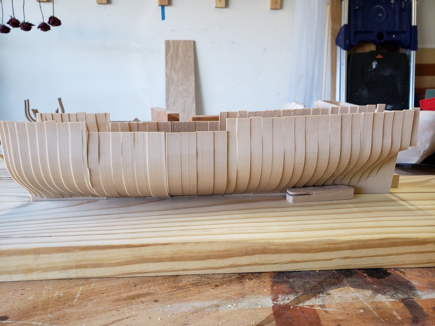
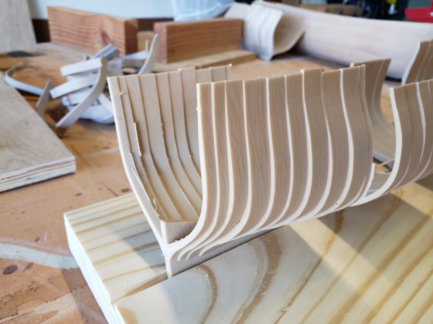
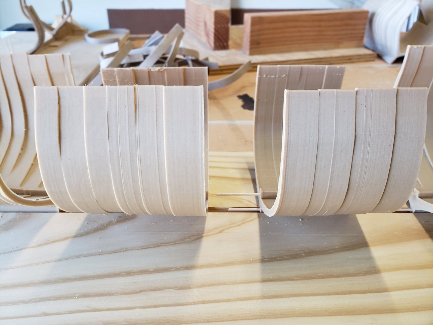
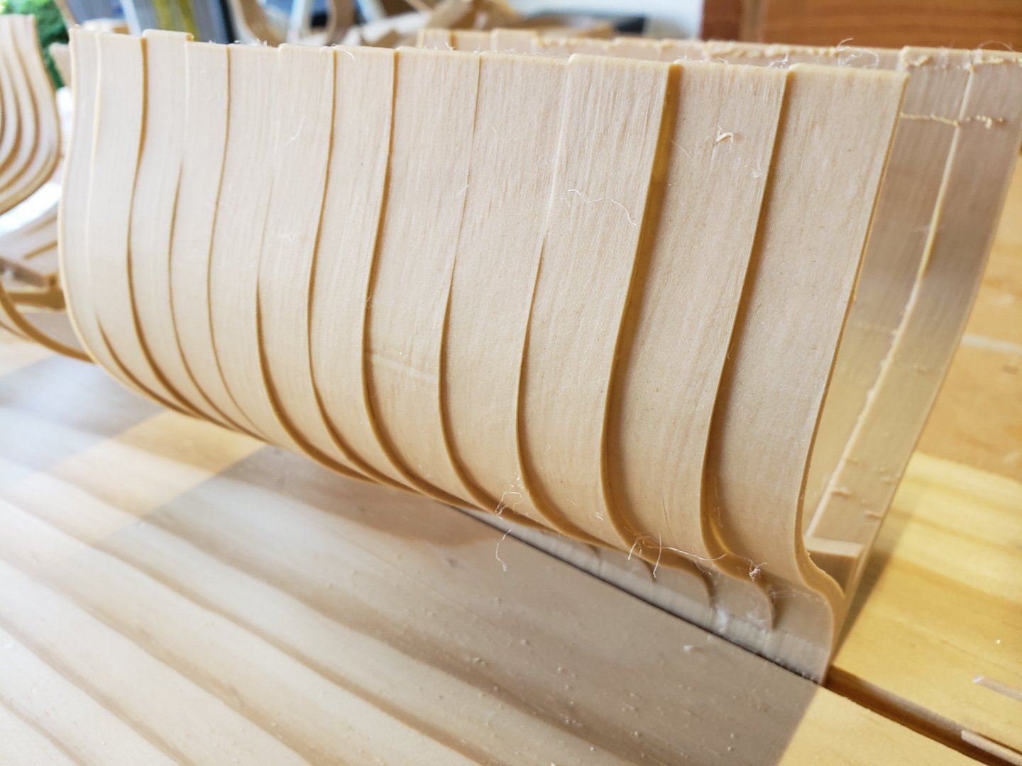
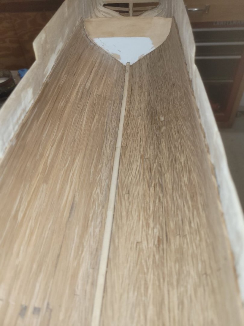
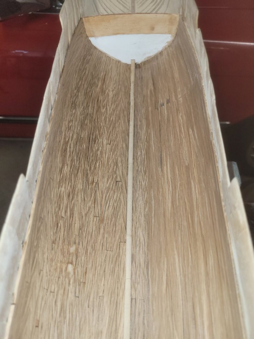
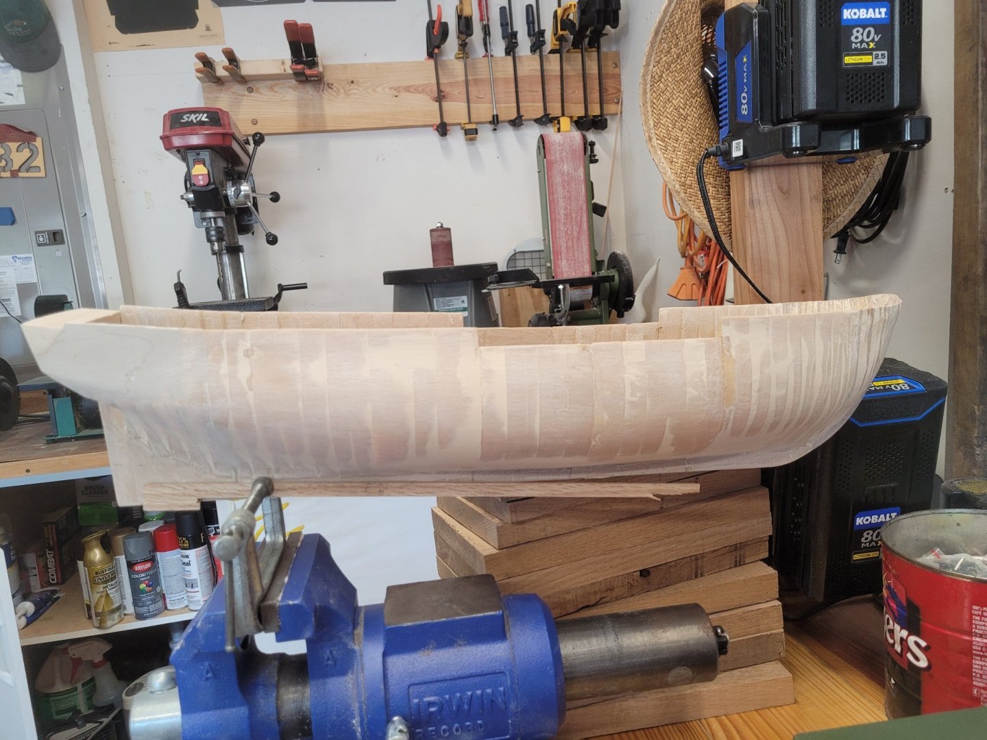
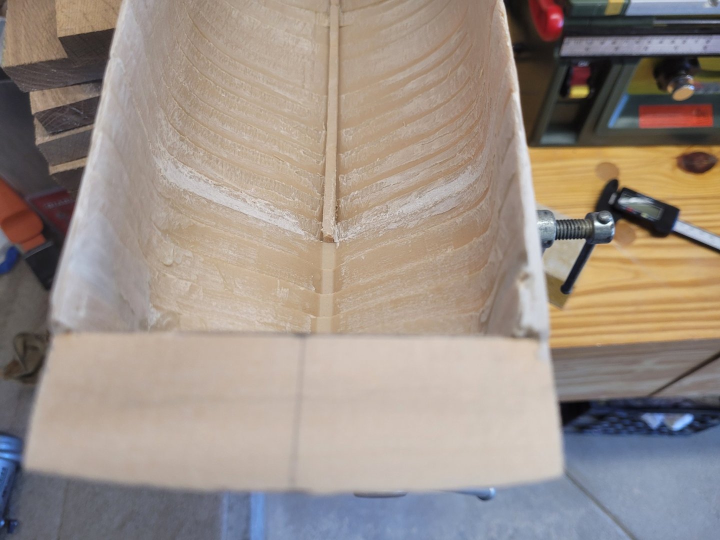
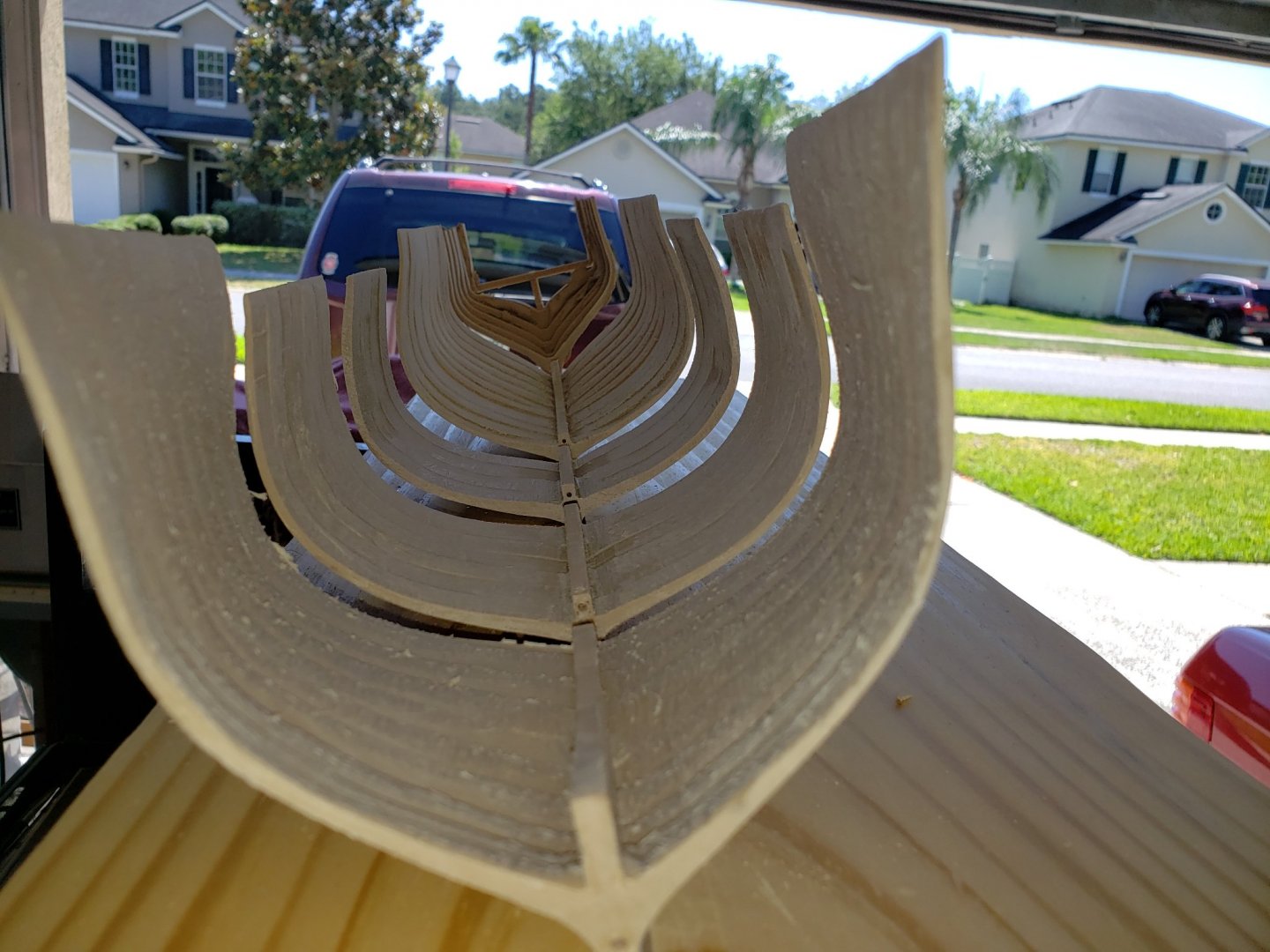
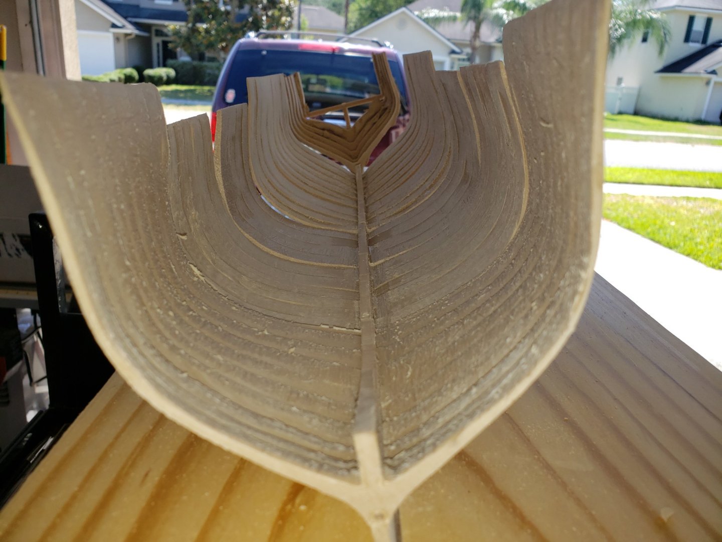
It has been a few months since I started planking the interior from the keel to the top of the gundeck. It is, for the most part, complete. Being the first time doing something like this, I really did not have an idea on how to proceed. So, the port side (which is the side I will be cutting away sections to view inside the ship) I decided to proceed from the top to the keel. It did not go as envisioned, but it went ok. One thing my father taught me when it comes to woodworking is that the skilled craftsman is one that is good at hiding mistakes. I will get to how I did that later. On the starboard side I went from the keel up. It did go better, but still some errors were made and had to do one adjustment plank if you will. Here are the pictures The first one is looking aft, the other, forward. Now, how did I hid my errors. The problem I encountered is the gap between the planks and butt joints was too great for my liking. Yes, maybe once painted they would not be as noticeable. In my youth I did a little surfing and I had to repair my own board. A couple of times the board hit a coral head or rocks and left a significant ding in the board. To repair this I scarfed out the foam under the fiberglass. I would then grate that foam down to dust and mix with a water resistant glue. I would then pour that back in the ding, let it dry, and refiberglass the board. After finishing touches, it was almost good as new. I used the same principle here. I saved all the dust from sanding, mixed it with a 50/50 mixture of wood glue and water until it was a pasty consistency and then pressed that into the gaps. Here are a couple of before, in process and after pictures Now that I have the interior planked to the top of the gundeck, next step is to plank the exterior. Before I do start on the planking, I will have to mark out the gunports and deck levels on the exterior. Cheers!
-
I am in the process of planking the interior. However, I am doing the entire ship from the keel up. At this point I have planked from the keel to the bottom of the gun deck on both sides. After I finished sanding and painting the interior sides, I will then install the decks (orlop and berthing). Before moving on to the next deck, I have to finish the deck below. Once you start on the deck above, it will be a challenge to correct something in the lower deck, so make sure it is to your satisfaction before moving on. With that in mind, my recommendation would be to plank the interior one deck at a time. Start at the top of the gun deck up to the top of the spar deck. Then finish the guns, hatches, galley, painting, etc, before moving on to installing the spar deck. In Marquardt's, the cross-sections illustrate that the planks are between the knees and timbers indicating the planks were installed before the planks. As for the waterways...let me know how you plan on doing that. I have been bouncing ideas through my head and come up blank. Overall, the project is off to a great start and this being your first build...very impressive.
-
Just a thought here Avi. For the first plank, use one piece that will go from stem to stern. This will, in my vision, provide you with a smooth flow of the curve from stem to stern for the 3.75in planks to butt up against. Reason I mention this is that I am planking the interior and used the short planks. It came out choppy instead of a smooth flow.
-
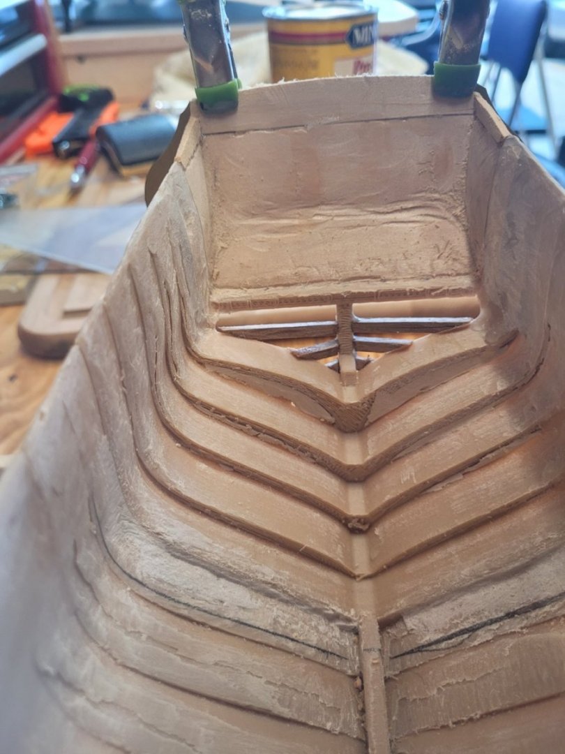
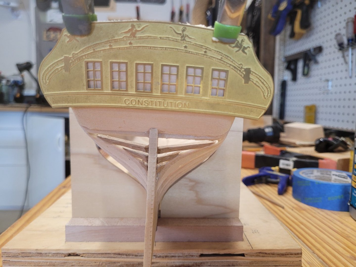
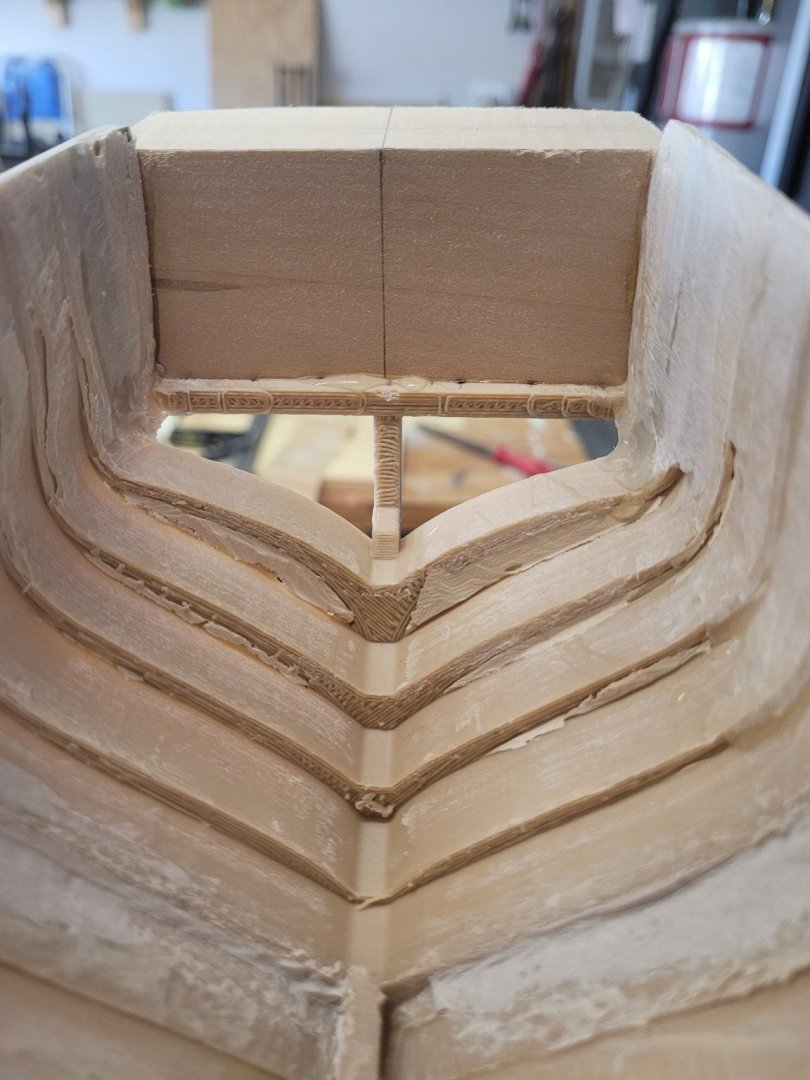
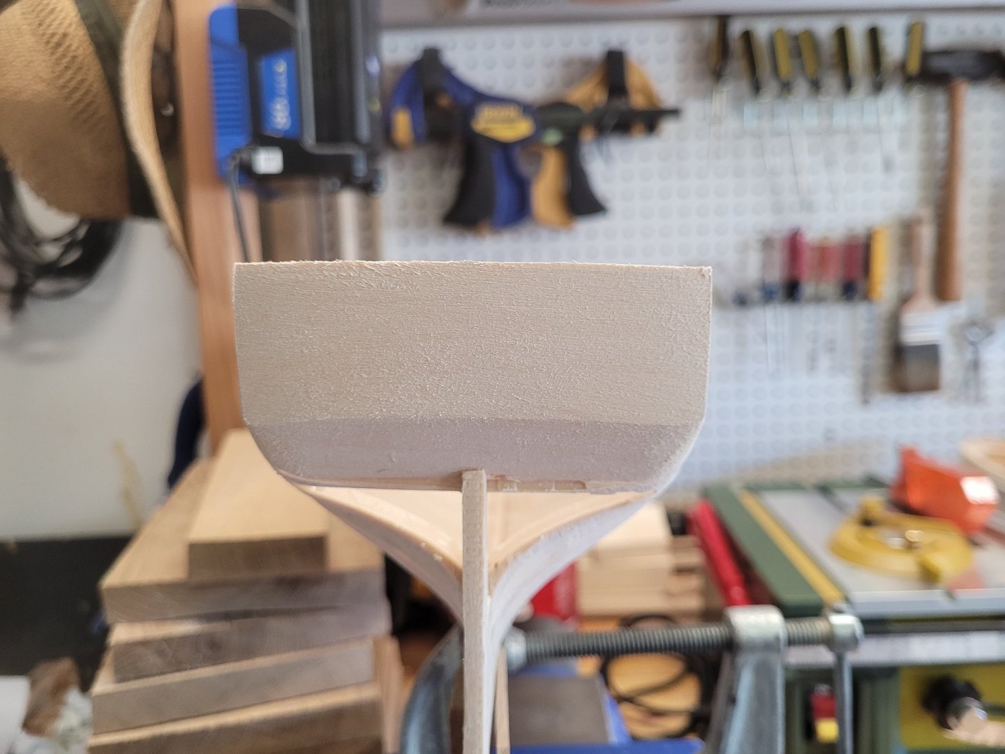
The transom/knuckle came out better than I though it would. Using a Dremel with wood carving bits and sanding drums, I was able to remove the interior to provide proper thickness of the frames/timbers. The resulting section is stronger than anticipated. My initial thinking was to plank the transom and knuckle area before carving out the interior, but through testing on a block of basswood convinced me that would not be necessary. Here is the result. Now, I know it does not look smooth and ready for a coat of paint. The interior will be planked as well as the exterior, so I was not to concerned with a finished appearance. And from the stern with the etched transom from the kit clamped on (just for testing, not attached yet). I did have to alter the interior plan a little. For the bilge, Orlop, and Berthing decks, I will only show from Frame 35 to Frame T. I found that while sanding the interior hull shell I could not sand the bow and stern sections smooth for two reasons. First being that if it did, the hull shell at those sections would become too weak and collapse, and second, I just could not get a sanding tool into those areas to effectively sand. So, I built two bulkheads at those frames as shown in the picture below. Next steps are to plank the interior from the bottom of the Gun Deck to the keel. To start I needed to mark the Gun Deck on the inside of the hull shell. I first marked the deck line on both sides of the exterior shell, and using the smallest drill bit that would fit in the Xacto handle, drilled through the shell to locate and mark the interior. That is where I will start with the planking and work toward the keel. Cheers.
-
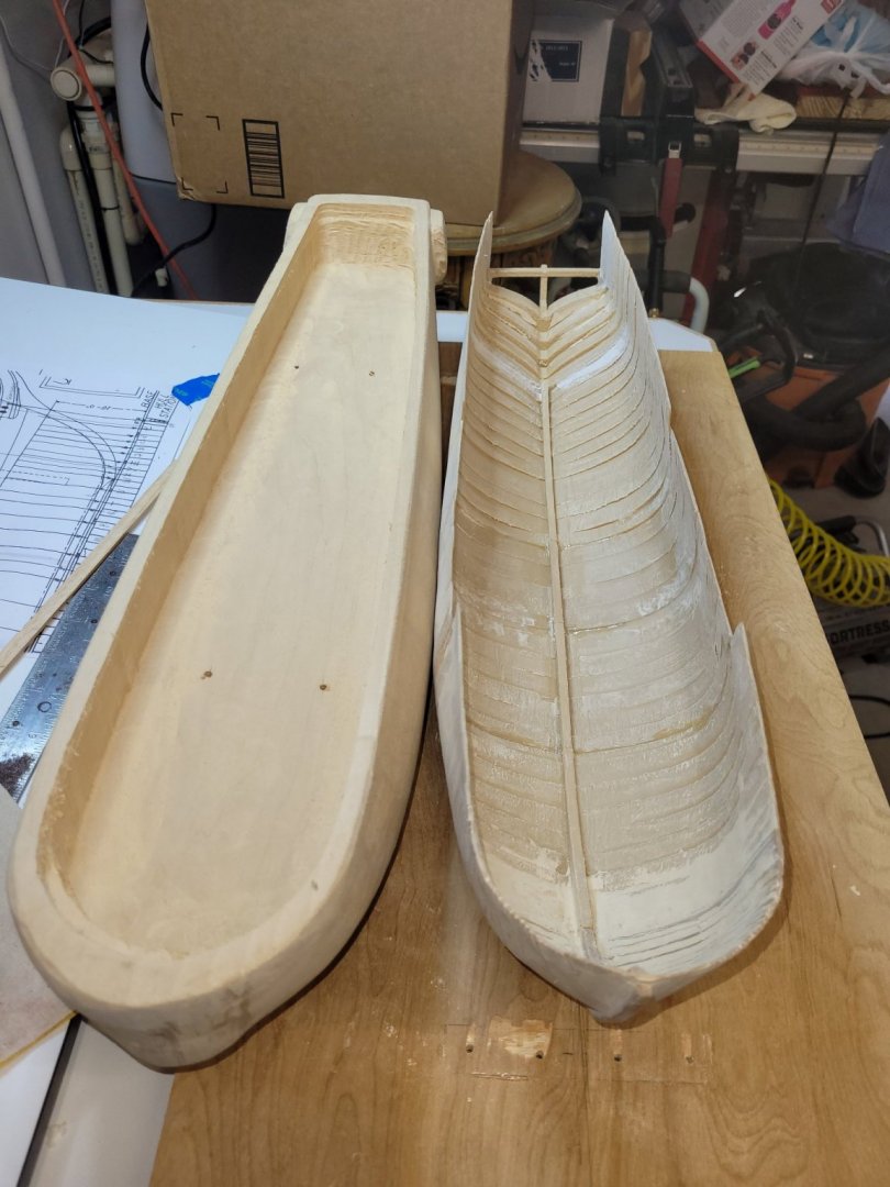
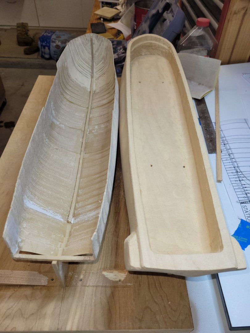
So, it has been some time since I last posted. Unfortunately, not much progress has been made. The hull sections are all in one piece now and sanded to form a relatively smooth hull shell which will receive planking on the interior and exterior. In the two pictures below, you can see the hull I manufactured using the 3D printer and the hull provided by BJ. The only section missing from my hull section is the transom/knuckle section. Which I will get to later. The transom/knuckle area did prove to be difficult. My initial vision was to fashion framing as the original ship is. I cut a couple of stern timbers to attach to the wing transom. Before attaching them, I tried to envision how I could get all the stern timbers cut and aligned with the laser cut transom provided in the kit, and have the strength to withstand the attaching process. I just could not see that happening. So, I decided to shape the transom/knuckle on the hull in the kit to get a better idea of what it should look like. And, how the galleries would be shaped. As I was shaping I though how can I transfer this onto my hull. My initial inclination was to cut that section from the BJ hull and attach to my hull. But, to be honest, that scared me. Something that drastic is permanent and if the plan with my hull fails, there is then no back-up hull. It then came to me to just get my own piece of basswood and shape the transom/knuckle from that and then attach it. As for the galleries, I will use the metal pieces from the BJ kit to build them and then attach them to my hull. Here is where it stands today. (Pictures in follow on post).
-
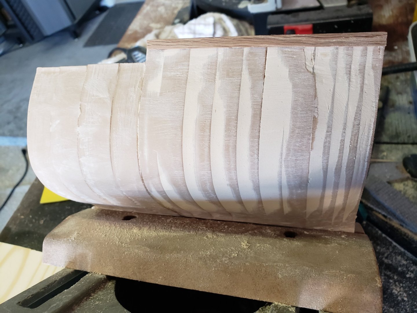
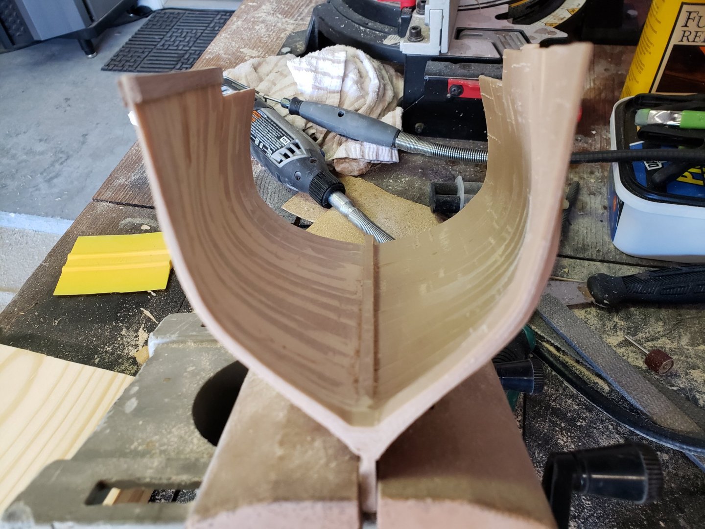
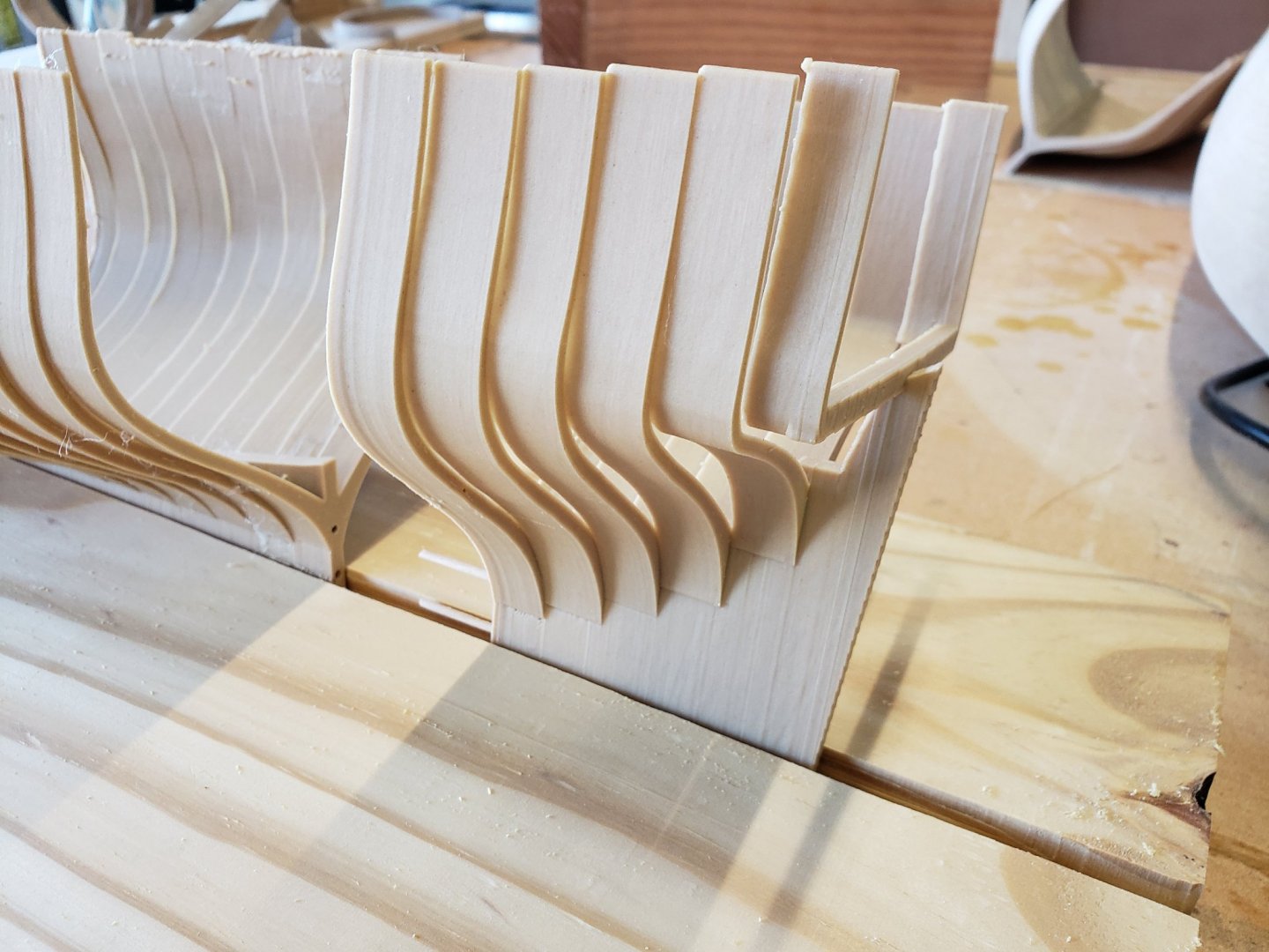
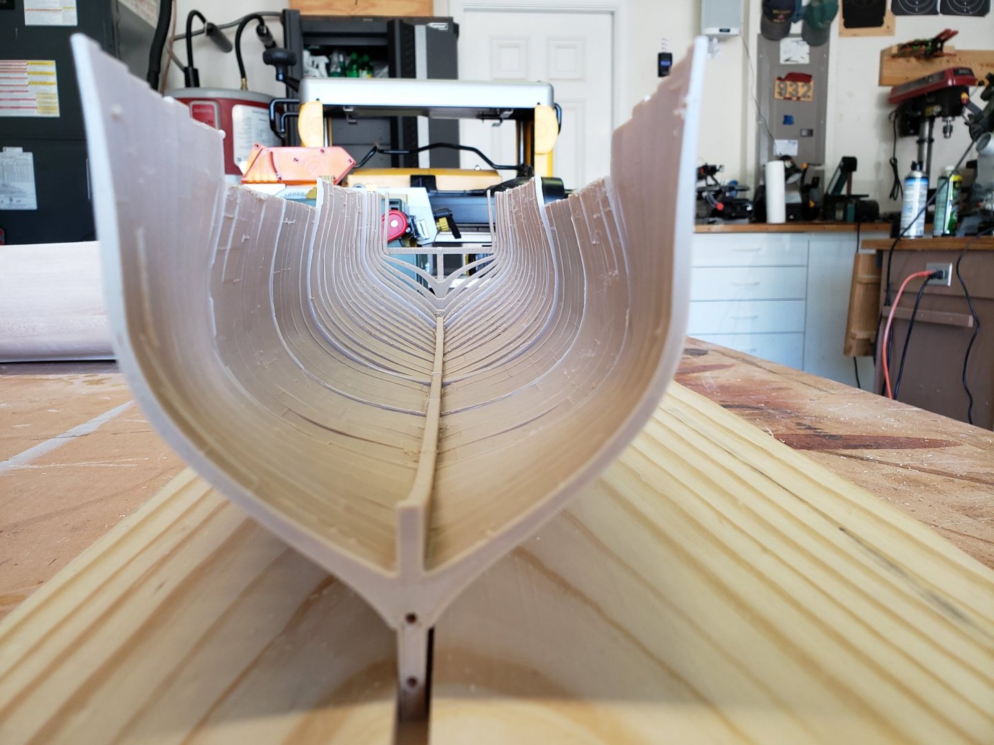
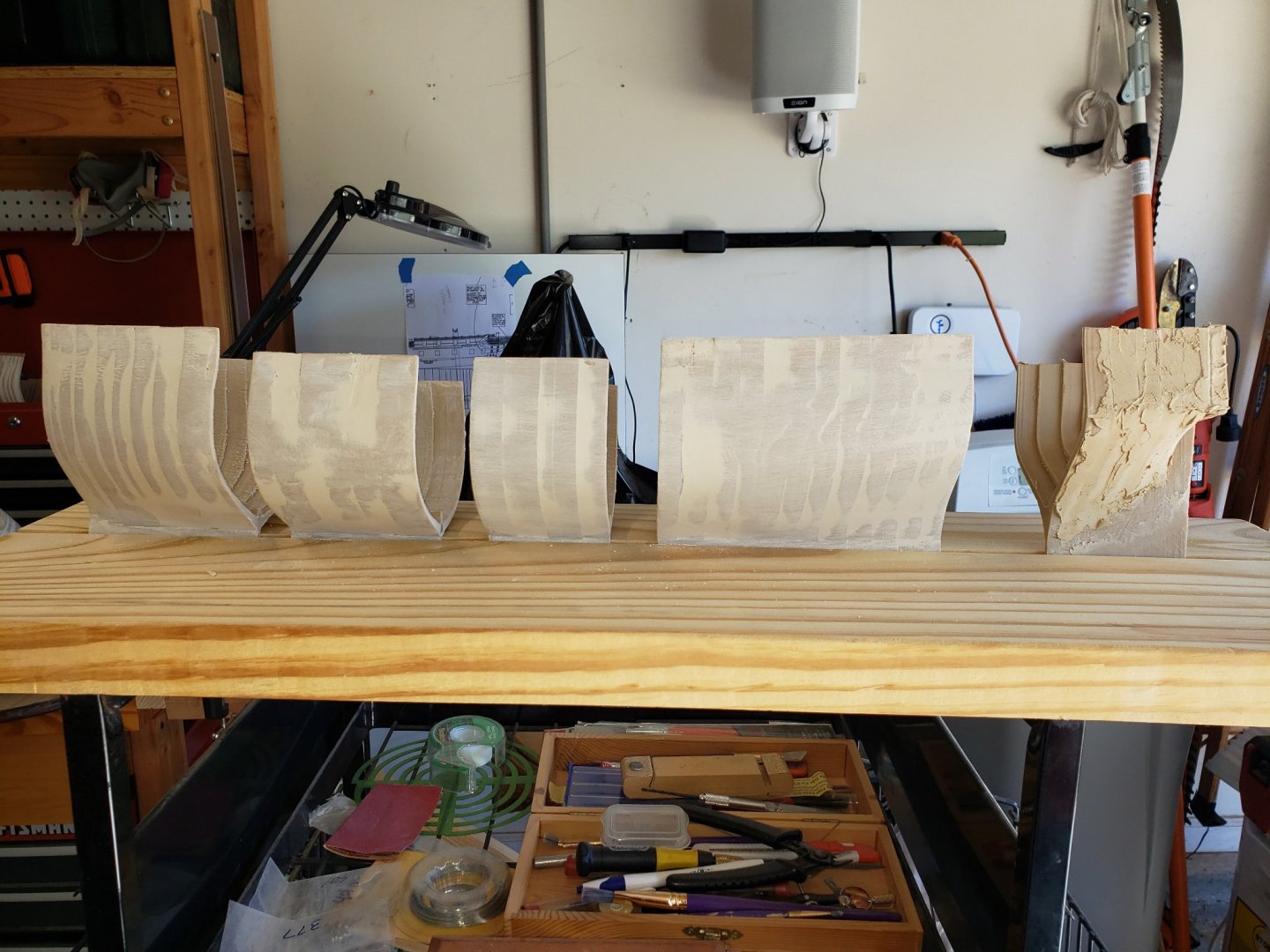
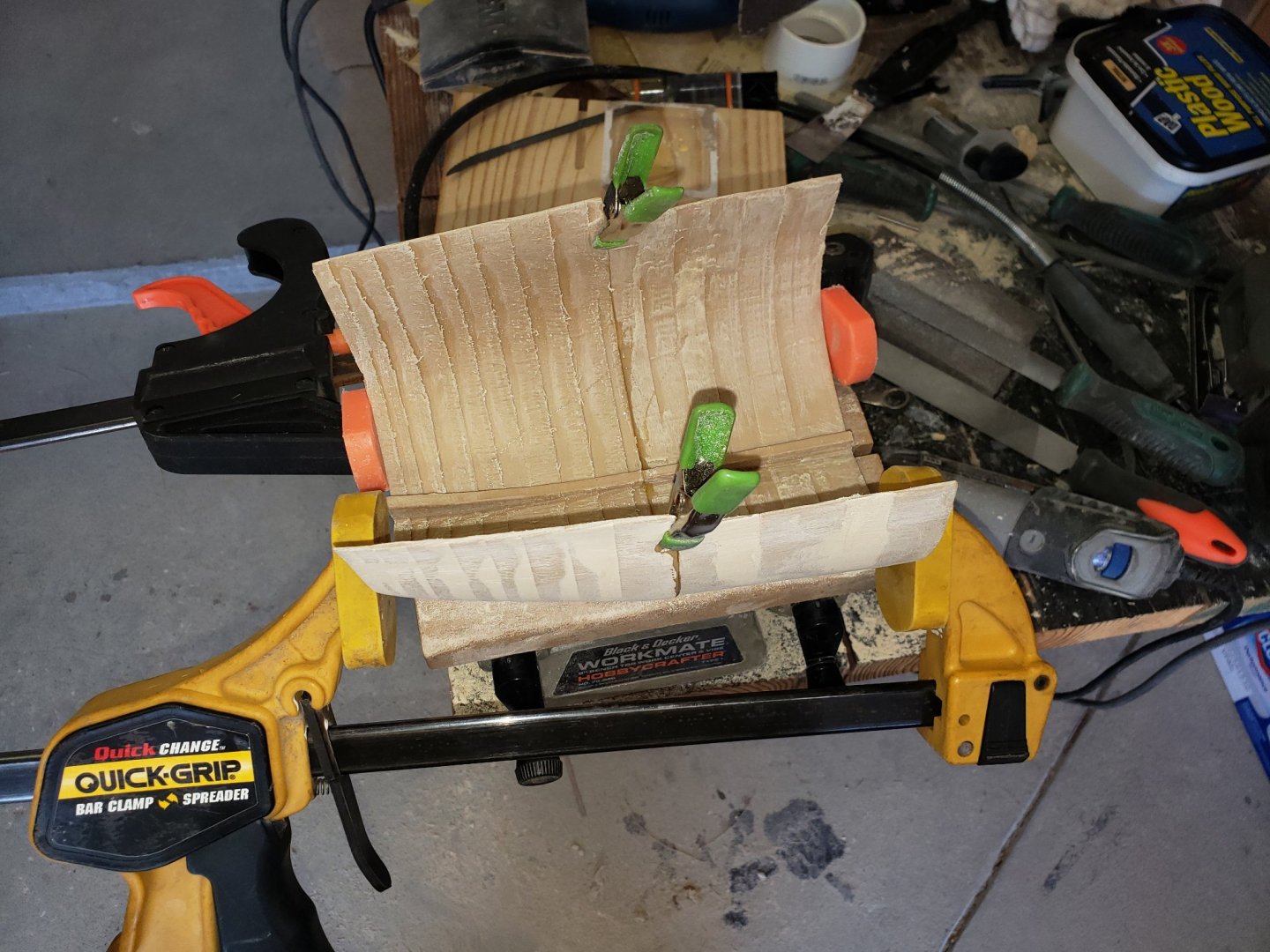
Still no bow. However, the rest of the hull has been rough shaped on the interior and the exterior hull has been filled in with wood filler and sanded smooth. I used wood rasps, 60 - 100 grit sandpaper for the exterior and wood rasps, a power drill sanding wheel, and a Dremel sanding drum for the interior. I removed the ridges between the frames down to about halfway (from aft to forward for the frames forward of midships from forward to aft to those frames aft of midships) into the frame it self. In the pictures the four sections between the bow and stern pieces are ready to be connected and then, when the epoxy is dry, sanded and filled in with wood filler. Once I get the stern piece shaped (in the picture below, it is basically shaped, just letting the wood filler dry before smooth sanding) and the bow completed, all pieces joined and the junction seams smoothed, I should have a "shell" hull ready to receive interior and exterior hull planking. In the last picture, two sections are epoxied and are drying. Making progress...slow, but moving forward. Cheers, Brian
-
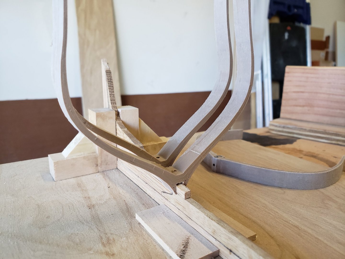
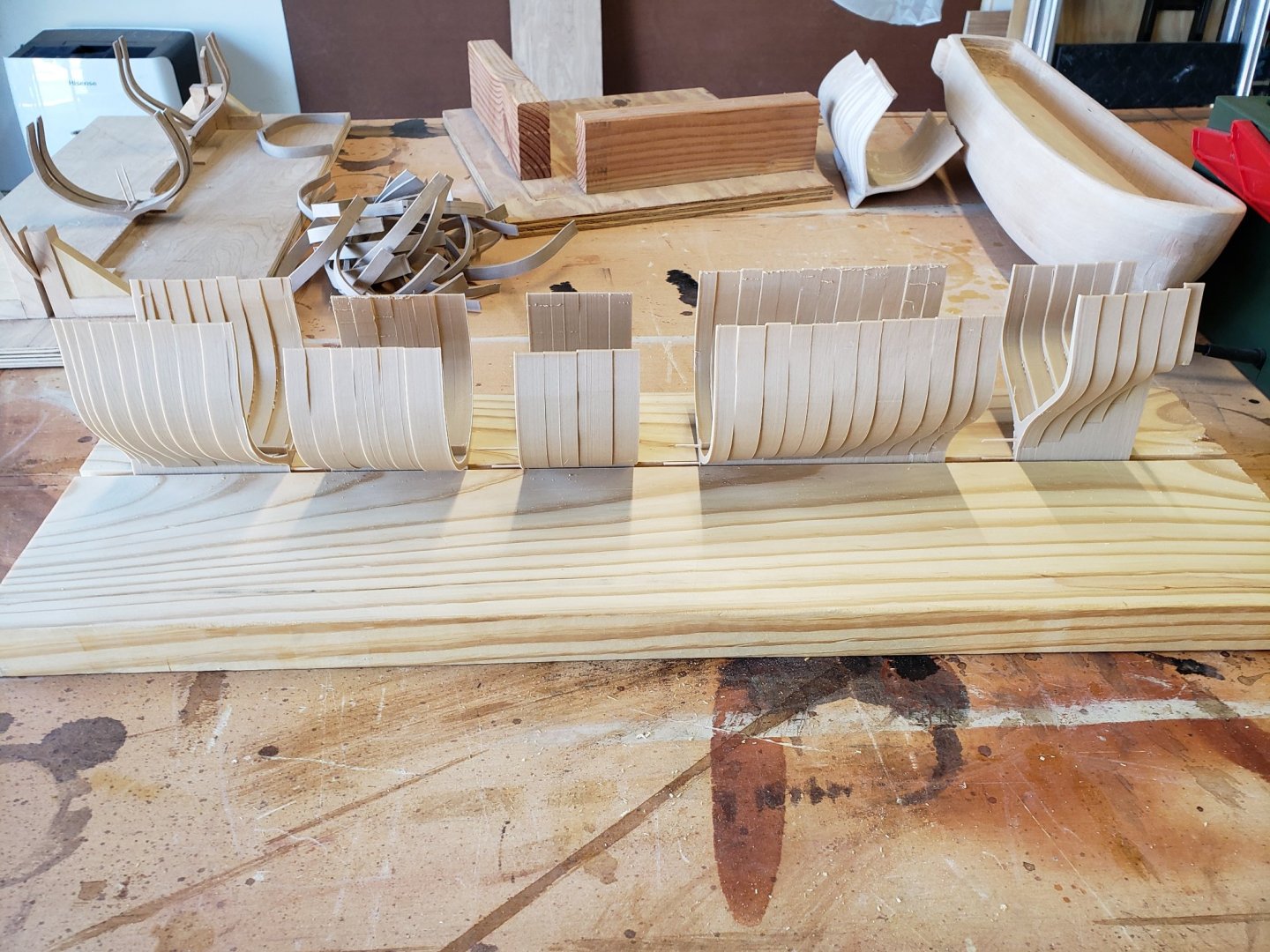
I printed out all frames, with the exception of the stern and bow sections. That section is going to be difficult to get right (more on that later). So, I decided to check my work and plan for the next step, attaching the frames to the keel. My initial plan was to print the frame with a toothpick size hole in the part of the timber that would rest atop the keel. A toothpick would then go through the timber into the keel to add longitudinal strength (first photo). I felt that would not be strong enough to withstand sanding and planking when the time came. So, I slightly altered the frames so that they would have a notch in the bottom that the keel would fit into. Next photo. I again felt that the frames would not be strong enough for sanding. That when I would sand them, they would flex inward, thereby rendering my sanding efforts ineffective for the most part. So, I then decided to experiment with a "shell". Pretty much printing out the entire hull from stem to stern, keel to top rail - well, close enough that I could effectively shape it using plastic wood and sanding. To do this I expanded the frame line fore and aft halfway to the next frame line thereby having the frames connected thereby providing mutual support between the frames and to the keel. I printed out from mid-ships to frame H in one section and frame J to U in another section. I added two holes in the keel at the forward and after ends to attach the sections. Using epoxy glue I was able to attach them with confidence that it would hold without concern. After that, I filled in the sides with plastic wood and then sanded. I used hand sanding, a couple of power sanders and a Dremel tool to sand them. Because of the strength, the sanding was effective. To test planking, I then attached a plank to the inside and outside of the hull. Normal wood glue works perfectly with the printed hull. Here is my test section. This gave me the confidence to press forward with printing out the hull using the hull section diagram from Bluejacket's manual. I have from the stern all the way forward to frame Y in the Bluejacket plan. Here are the pictures. So, I pretty much have it all with the exception of the bow. That is proving to be difficult. I have printed it twice already and have significant strength issues. The frames do not connect with each other when I expand the forward frames fore and aft like i had done with the rest of the ship. I am now doing it in small increments, of .03". So, it is taking awhile to get the frame designed in Tinkercad. Once I do, will post the pictures there. But this is where it stands now. I am about ready to shape the hull to prepare it for planking. Regards, Brian
-
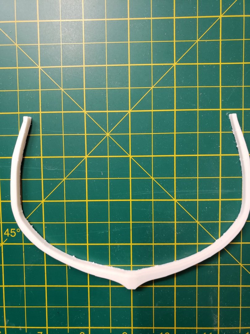
So, that attempt was back in May. I had other ideas - try and cut the wood to 1/8th thick and glue two pieces together with the grain perpendicular to each, place pins in the joints, etc... Each thought would resolve one issue, but would increase another, mainly time. So, I started digging around and decided upon a 3D printer. I am still using BlueJacket's plans and drawings to draw out each frame and from those drawings, creating the 3D file which will be then used to create the frame. I know this is "cheating" a little, but given the time constraints and risk with using wood frames (one breaks in during construction - or worse, after it is completed), I am opting to use the 3D printer - hey, I WILL be using Wood Filament for the frames...so, I am staying as close as possible. 😉 Here is the same frame as above, Frame C, but from the 3D printer. It is pure PLA filament that came with the printer. This frame was just a prototype. It is stronger - tested by squeezing the tops of the frame together - did not break. And accurate, as you can see the tops are level, and the beam is the same on each side.
-
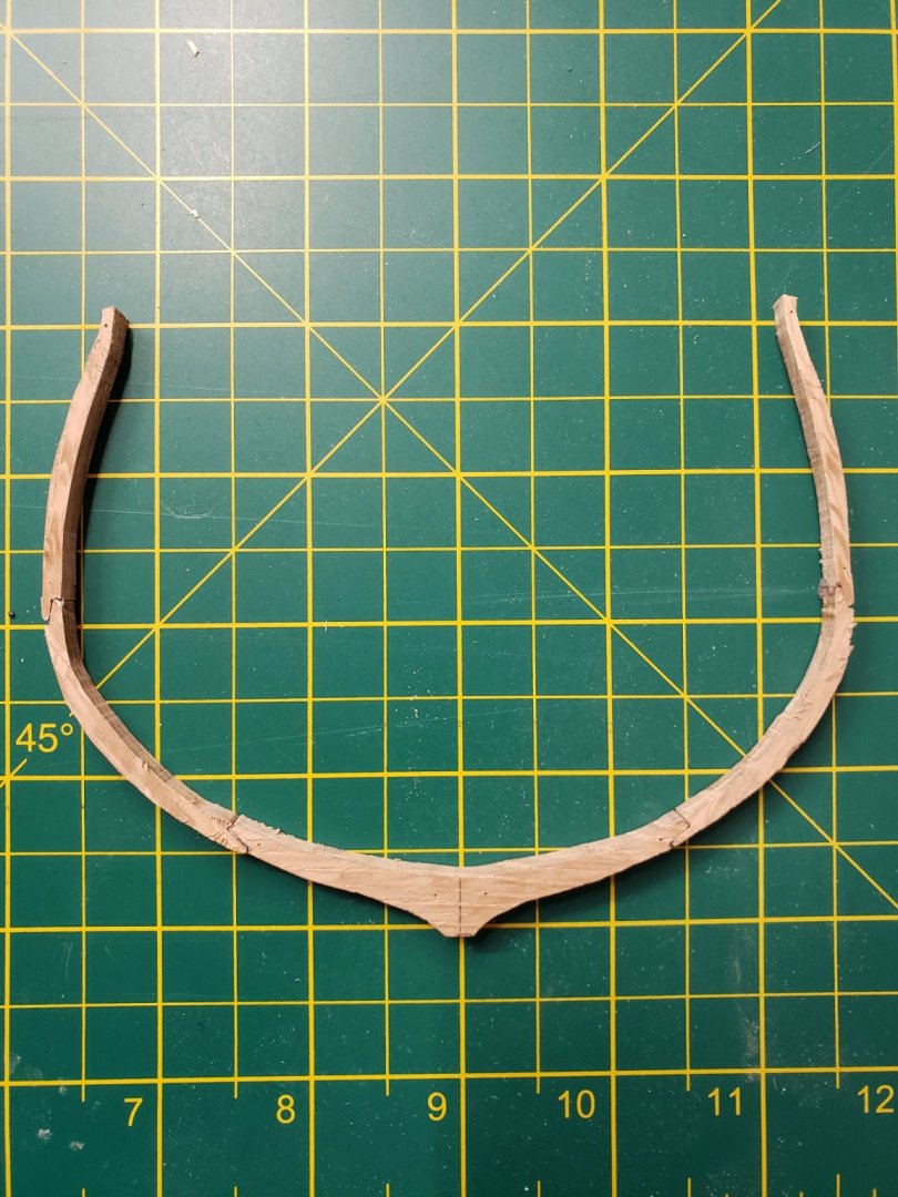
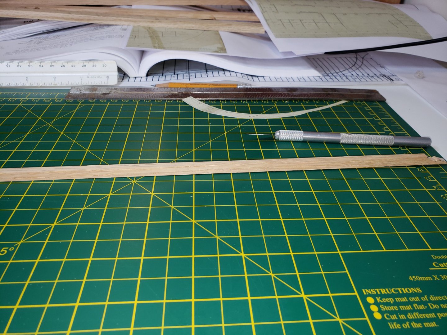
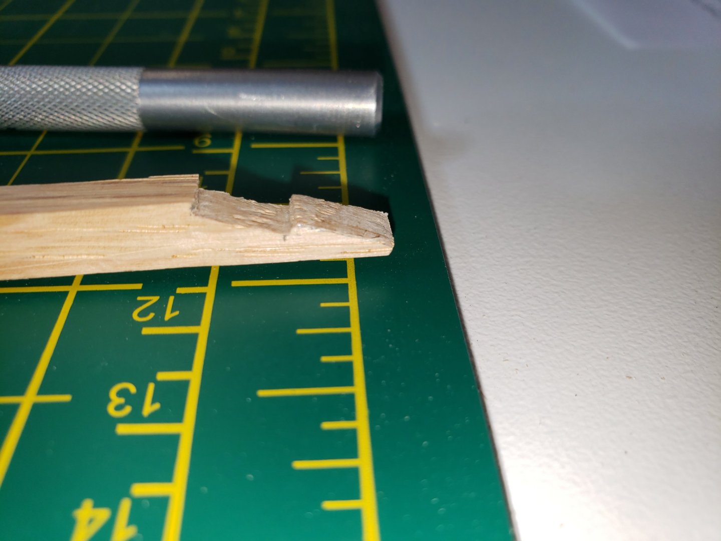
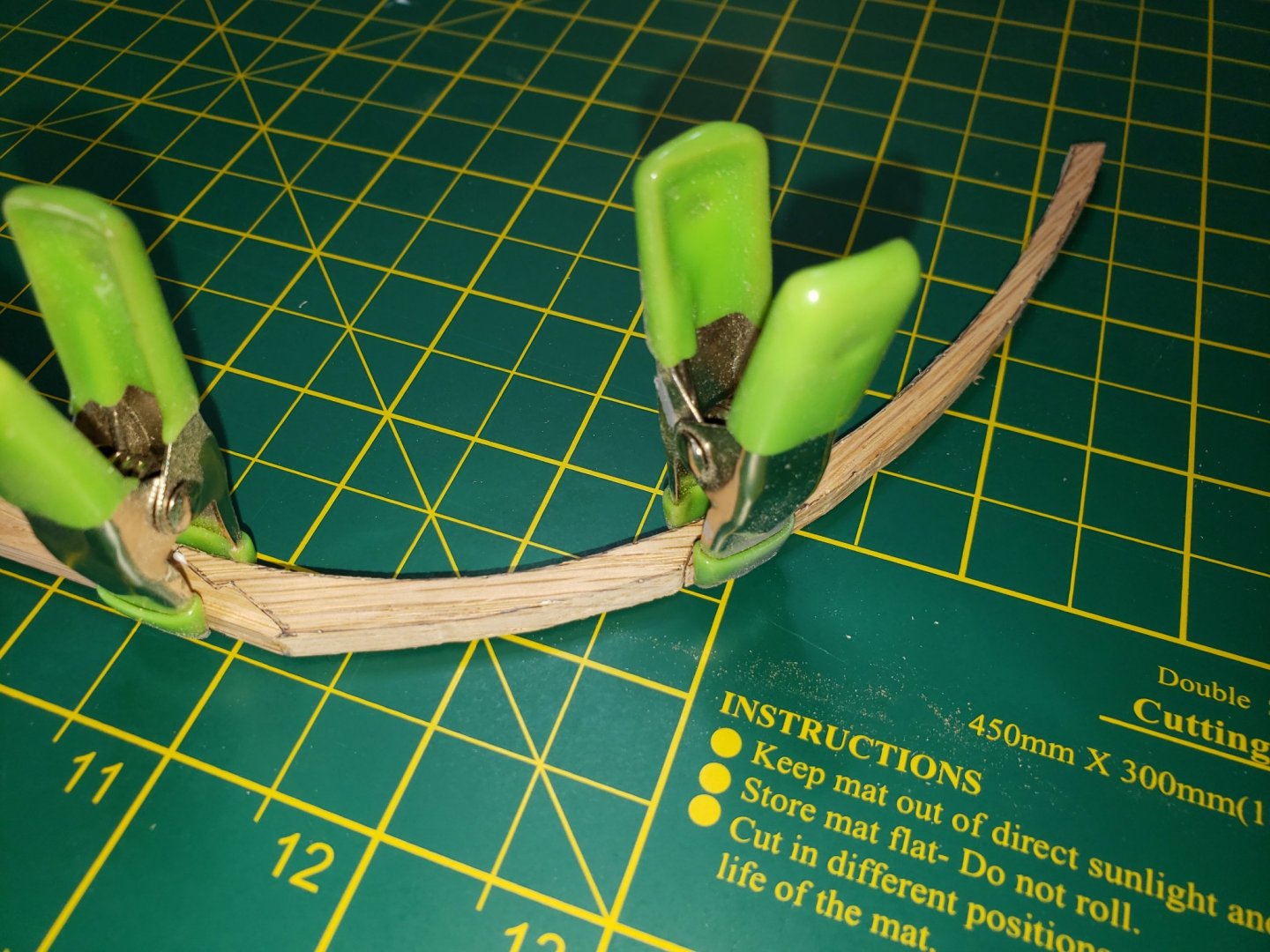
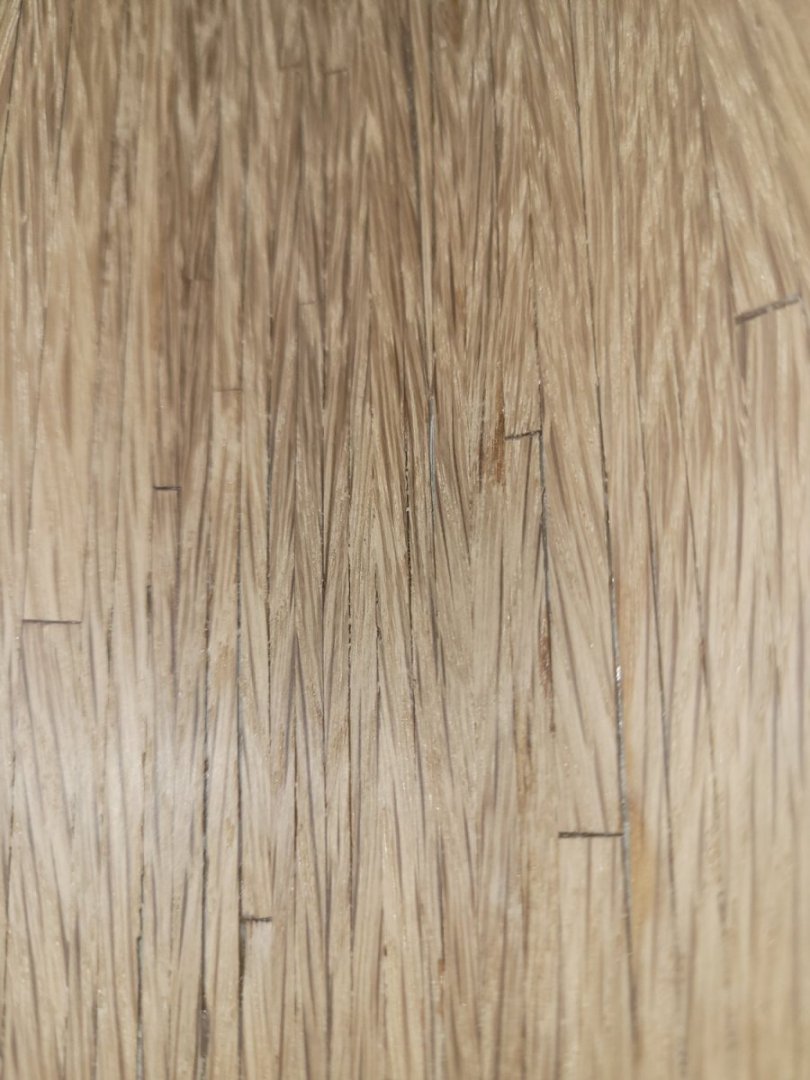
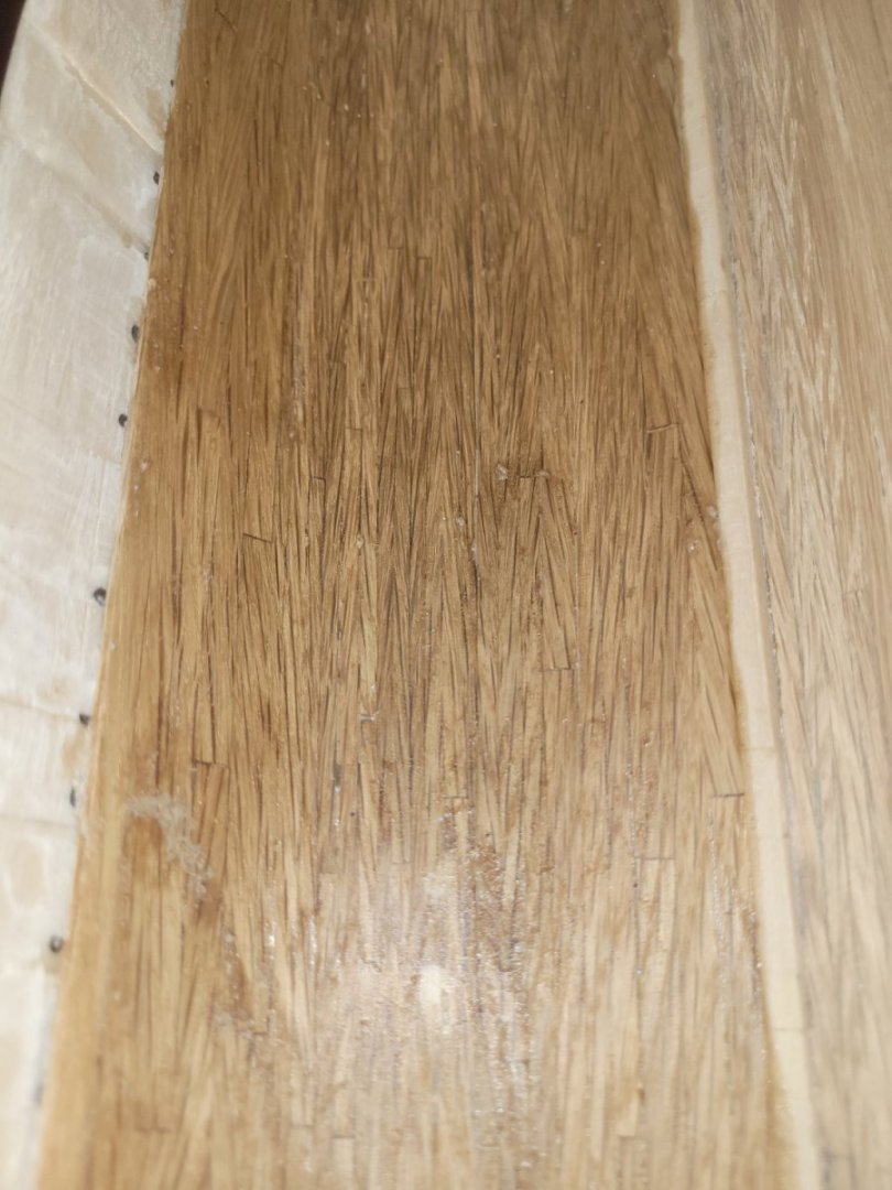
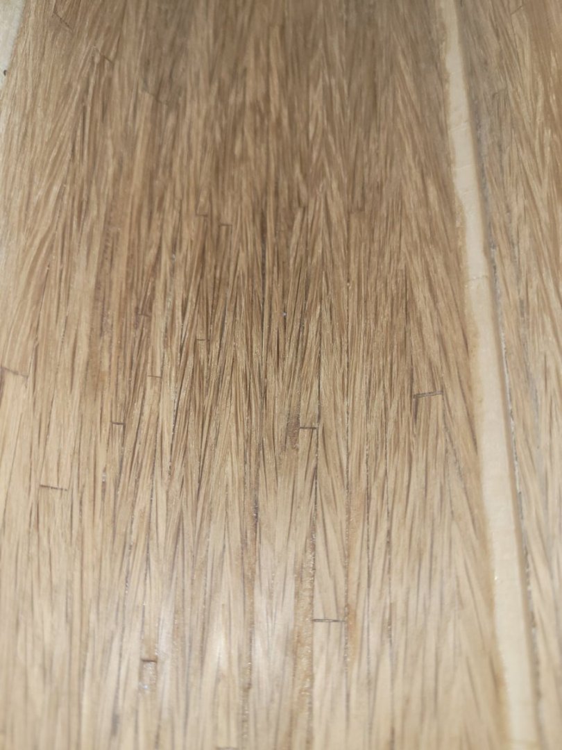
It has been quite a while since I have posted. Dealing with family issues, my own health issues, and just could not figure out how to build the frames out of wood with enough strength in them to withstand the construction process. My first attempt failed miserably, so bad, that I threw it into the trash out of disgust without thinking to take a picture of it. My second attempt, I divided the frame into 5 parts in order to keep the wood grain as close to parallel to the frame as possible. Using Frame C as the guinea pig, I cut the five pieces out of white oak at a thickness of 1/4". Using an S joint (guess that would be a good description) to join the pieces together, I glued them using wood glue and clamped for 24 hours. The following day, went out to check on my work and it all looked fine. I unclamped the pieces and then was checking the strength of the frame by slightly pressing the port and starboard ends together. Immediately, the top S joint on one side snapped free, ending that test and ultimately, this process of wood frames. I needed to find a way to build stronger frames and which did not take days just to build each one. Additionally, the frame was not too accurate, so include that in the development requirements. This is the wood frame:
-
Thanks Roger. the pelorus' were purchased from shapeways.com. I initially had made two out of wood and was not completely satisfied with them, but they were all that I had. I did stumble upon shapeways when I was looking for the eggbeater antennas. The 35' whips, the eggbeaters, the big eyes and the pelorus' were purchased from them. As for the CPP, I struggled with those. Those were made back in 2009. I looked through all the model ship building websites in an attempt to find a port and starboard CPP and could not. They were pretty much fixed screws, and right hand at that, and wrong size. Yes, they were 1:96 scale, but for a destroyer, cruiser, etc. None for a Minesweeper. So, I decided to fashion my own out of wood. I initially tried to put some forward pitch on the blades but could not get the pitch uniform across the eight blades. It was at that point I decided to mount the ship as if she is pier side with 0 pitch on the screws.
-
Tom, DANG! Now I have to take it out of the case....just kidding. That is a great example of planning. I installed the starboard pigs and otters before thinking about the aft steering hatch. Just could not get it in between the two. As the DCA on ENGAGE, aft steering was my space, it was the DC workshop. And with two DCmen that were, well, a little on the large size, I chuckled every time they had to go through the scuttle.
-
Very nice! Patience is definitely a necessity doing this.
- 16 replies
-
- constitution
- BlueJacket Shipcrafters
-
(and 1 more)
Tagged with:
-
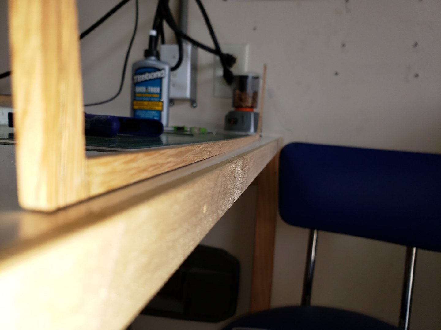
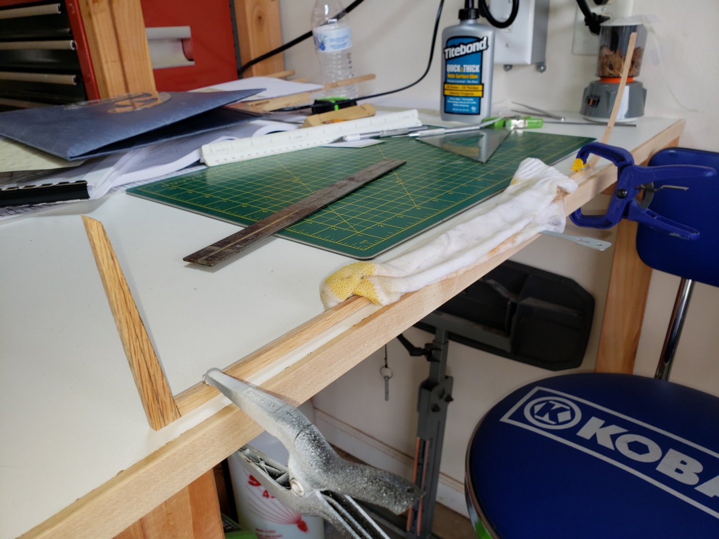
Picking back up on this build after finishing and placing in a display case (finally!) the previous build. As I left off, I went down to my parents house to include my father in on the build. Well, did not go as well as I had envisioned - unfortunately. Guess eventually we all will reach that point. I have a little re-work to do on the gun carriages. Picking back up, as you recall, this is to be somewhat modified. I am going to build the hull as a plank on frame construction in order to open one side of the hull, all decks for viewing. My first was to do a little research in order to get a better picture of the keel. From the National Archives, I was able to pull the drawings Samuel H. Pook drew in 1849. Though not from 1812, it is well known that the keel is the original thus I felt Pook's drawings would be accurate for this purpose. Additionally, I reviewed SCRATCH BUILDING A MODEL SHIP by Gene Bodnar (August 2007) and his build log when he built the CONSTITUTION in 4 sections. The document is located here: http://modelshipworldforum.com/resources/plans_and_research/ScratchBuildingaModelShipgene.pdf and the build log is on another ship model building website. The keel is as the CONSTITUTION's - white oak. I elected to use a single keel, not two sections. To get the proper size (1/4" x 3/16") of the keel, I used a planner. Then, using a scroll saw, I cut the forward joint (where the bow stem meets the keel). Then measuring back from that joint, I cut the stern end of the keel. I did this process just in case I fouled up the bow to stem joint I wouldn't have to re-plane a new keel all over again. The bow stem is made of two sections such that the curvature of the stem would follow the wood grain giving it the most strength. After attaching the bow stem, using the Pook drawings again I cut out the sternpost and glued that to the keel. After the glue had dried overnight, I then drilled holes at each joint just tight enough to insert a toothpick. I then inserted a glue coated toothpick into each joint providing additional strength to each joint. Once done I place the keel on the work table and saw that I was starting off with a little sagging (you can see the stern is a little off the table). To remedy this, I place a small piece of metal under the keel at midships and then clamped down the stern and bow sections. I then place a wet sock (shop rag now) on the keel and let it set overnight. This, at last check, remedy the sagging and I now have a straight keel to work from. Next step is to start on the frames - which again, will be using Bodnar's document as a guide.
-
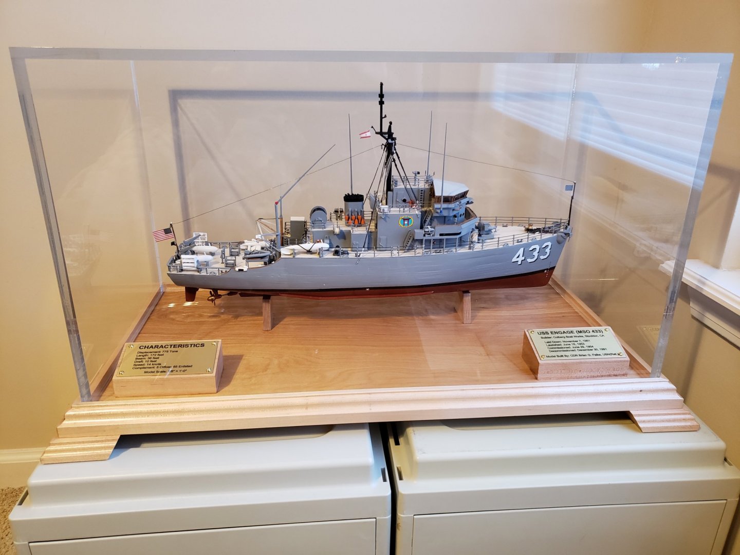
Down to the final details, which I have been trying to figure out how to make since I began the model. The antennas. The MSO has 4 35' HF whip antennas and the 4 Fleet Broadcast antennas (egg beaters). I began sanding a 1/8" dowel in an attempt to achieve the right size for the whip antennas. I would get close, but each time, due to the thinness, it would break setting me back to the beginning. I tried maybe 5 times until I gave up. I did look at using wire as the whips, but it just did not look right. Too thin at the base, no tapper, and very difficult to get the wire straight. As for the egg beaters, I did not even attempt to build them. I just mulled thoughts through my mind. I came up with a couple of ideas using a toothpick sanded down as the center post and then bent wire as the egg beater part. With nothing left to lose, I did an internet search for "1:96 scale model parts" and one of the top returns was Shapeways.com. My interest was piqued. I went to the site and search on 1:96. A lot of 3D designed parts and pieces for ship models came up - all kinds of pieces from USS CONSTITUTION to the latest Navy destroyer. I felt like a kid in a candy store now. I found a plethora of detail pieces that I could use. Including the 35' whips and the egg beaters. I also replace the big eyes and the port and starboard pelorus'. The whips were not smooth, however, they were a heck of a lot better than a piece of wire or a fat whip made of wood. I do not have detailed pictures of the antenna's. However, I have completely finished the build. As I read somewhere in another build, if you do not put the model in a case, you will continue to tinker with it - never really finishing the project. That was completed yesterday. The base, ship mounted and the clear enclosure. I built the base and the clear acrylic box is from shoppopdisplays.com (I do recommend them). Now, the COMMCMDIV 11 burgee and shield. That was a personal touch. In the Navy, the command burgee or pennant of a senior commander would replace the commissioning pennant when that commander was embarked onboard the ship. MCMDIV 11 was my first of two operational commands. Though ENGAGE was long gone by the time I was in command of DIV 11, she did spend some time during the Vietnam War in Sasebo, Japan (where MCMDIV 11 was homeported under 7th Fleet). So, I felt, given the linkage there, and that ENGAGE was my first operational tour and DIV 11 was my last (DIV 11 and DIV 31 merged in 2009 becoming MCMDIV 31 under 3rd Fleet which I continued to be the commander for), it was fitting that I permanently "embark" the ship. Cheers, Brian
-
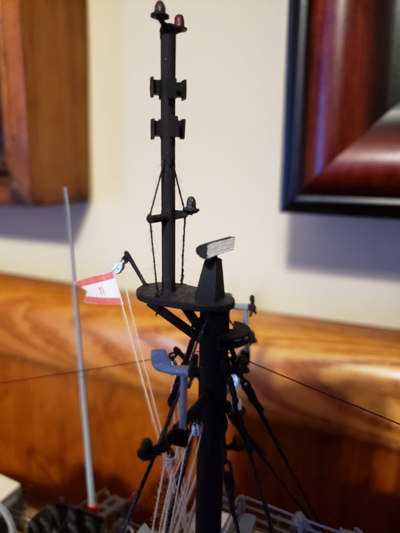
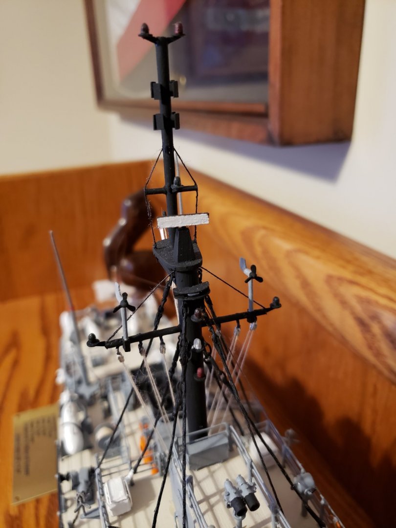
It has been awhile since I have posted, so I might as well get back to it. As I left off last, the mast was next in line for logging. Masts on MSOs are not complex, the most technical piece of equipment on the mast is the surface search radar. However, there are a couple of unique sensors on the top part of the mast. These are the earth's magnetic field sensors used to determine the amount of current for each of the four degaussing loops for the ship to remain "invisible" to magnetic mines. Then there are the two wind measuring birds. These were very difficult to construct. First, the only picture I had of these where I could closely determine their actual size and scale them down was in the Interior Communications rating book. I was able to find a picture of a Sailor holding one and guessing the Sailor was about 6', I went from there. Then I had to make two that were, to the naked eye, exactly identical in size and shape. I think I went through 20 - 30 iterations of the propeller blades until I got 6 that were close and then glue them on the hub at the correct angle for each blade. On any other naval ship model, I think I would have skipped them, but on a 1:96 scale, and with such a bare mast to begin with, they would have noticeably been missing. Now, one more unique characteristic of the MSO mast, the three green lights. One on each end of the yardarm and one right above the radar. These are used for when the ship is conducting mine clearing operations. The additional lights are, at the top of the mast, the aircraft warning lights and the red, white, red lights on the front for various possible emergency conditions while underway. And, lets not forget about the aft masthead range light. You may notice the Division Burgee closed-up on the mast instead of the typical commissioning pennant. That is MCM Division 11 Commodores' burgee. More on that later in the build log. The mast is black where in the picture of USS ENGAGE in my first post it is haze gray. Why the difference? Back, when I first reported aboard ENGAGE, all masts on all USN ships were black. This was to hide the soot that would build up on the masts in the old coal boiler ships and became tradition until about 1989/90 when it suddenly came down from the CNO that all ships are to paint their masts haze gray. The story behind the change, and I cannot vouch for this, is that the CNO was out sailing with some British friends one afternoon in the New England area when they spotted a naval vessel off in the distance. Too far to make out nationality by viewing the flag, so one of the yacht owners grabber her binoculars and quickly let the CNO know that it was a US Navy ship. He looked through the binos and could not see the flag and then asked her how does she know it is a US Navy ship. Her reply was that only US Navy ships have black masts. Thus, the order for all US Navy ships to paint their masts haze gray and that remains the standard today. I elected to keep it black to add depth and character to the ship model and that is how it was when I first stepped aboard.
-
Yes, that is correct. Being on the East Coast, it is a little difficult for me to get to the restoration project. However, I am following along through their Facebook page. The team is doing a fantastic job with the restoration. The ENGAGE was build in Stockton - think it is one of 3 Stockton built MSO's. In total, there were 102 laid down. The final MSO was stopped after the keel was laid down. After a few years of enjoying the model, my intention is to donate the model to the USS LUCID Museum.
-
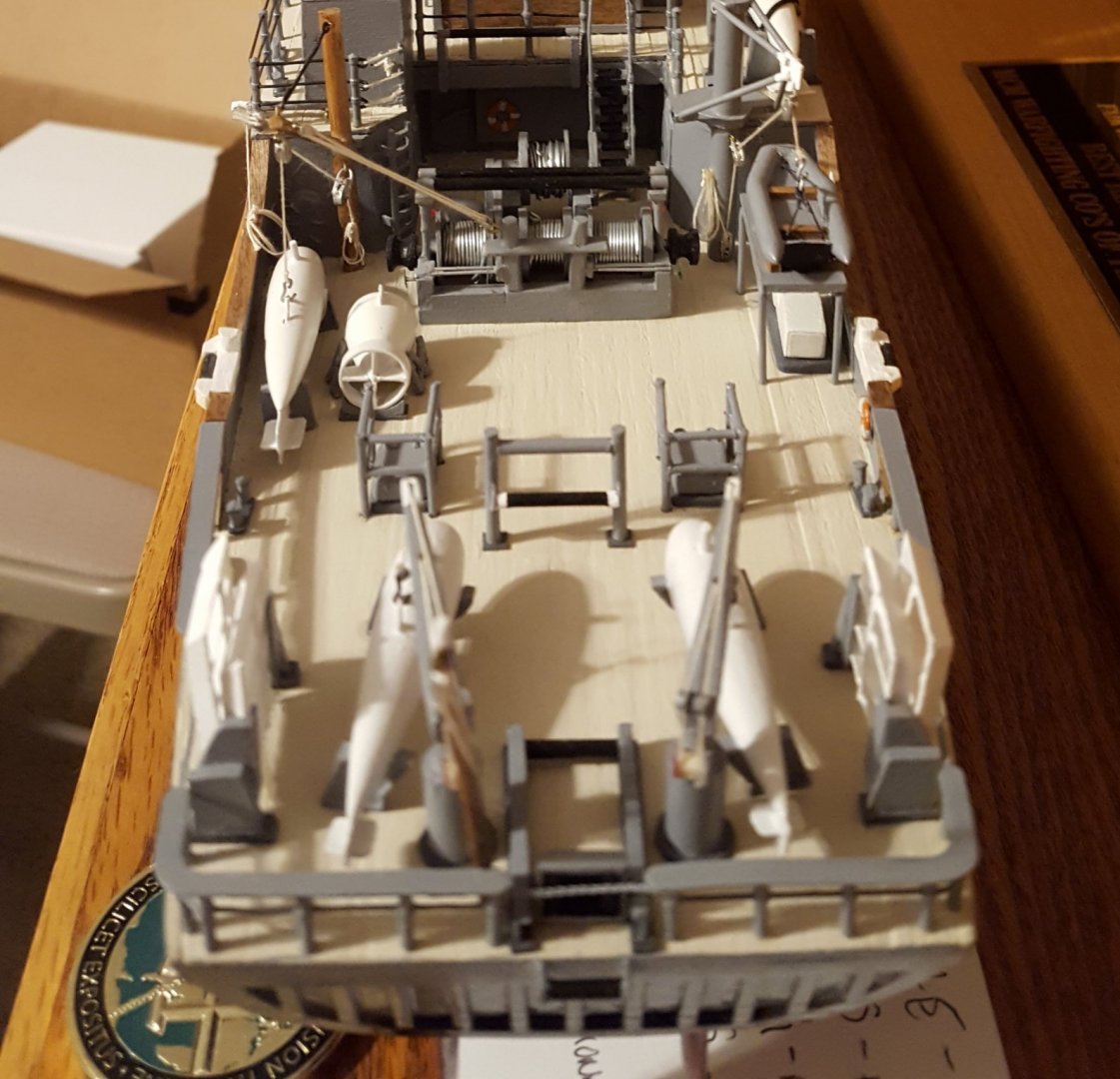
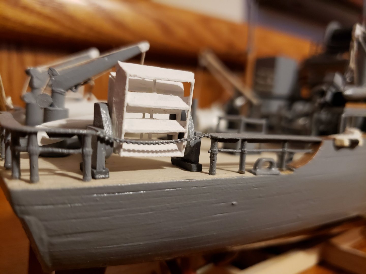
At this point, all fantail equipment was completed and in place. To complete the fantail I still needed to install the taffrail. I could not find stanchions that would work without some modification. I used the same stanchions I used on the focsle, just cut them off right at the second rail and filed flat for the rail to rest on. Though not 100% accurate, it did come close enough. Now that the fantail was completed, and for the most part, the entire ship's hull and deck equipment, I shifted my efforts to the mast. This I felt was going to be a challenge because I did not have clear pictures of where mast lights, antennas and sensor's were located on the mast.
About us
Modelshipworld - Advancing Ship Modeling through Research
SSL Secured
Your security is important for us so this Website is SSL-Secured
NRG Mailing Address
Nautical Research Guild
237 South Lincoln Street
Westmont IL, 60559-1917
Model Ship World ® and the MSW logo are Registered Trademarks, and belong to the Nautical Research Guild (United States Patent and Trademark Office: No. 6,929,264 & No. 6,929,274, registered Dec. 20, 2022)
Helpful Links
About the NRG
If you enjoy building ship models that are historically accurate as well as beautiful, then The Nautical Research Guild (NRG) is just right for you.
The Guild is a non-profit educational organization whose mission is to “Advance Ship Modeling Through Research”. We provide support to our members in their efforts to raise the quality of their model ships.
The Nautical Research Guild has published our world-renowned quarterly magazine, The Nautical Research Journal, since 1955. The pages of the Journal are full of articles by accomplished ship modelers who show you how they create those exquisite details on their models, and by maritime historians who show you the correct details to build. The Journal is available in both print and digital editions. Go to the NRG web site (www.thenrg.org) to download a complimentary digital copy of the Journal. The NRG also publishes plan sets, books and compilations of back issues of the Journal and the former Ships in Scale and Model Ship Builder magazines.



.thumb.jpg.023bf95fe66a4bdea98b02271a1c11fe.jpg)
.thumb.jpg.1bfebe2ceb1f94d207bc8efcb5b5e341.jpg)
