


iMustBeCrazy
-
Posts
976 -
Joined
-
Last visited
1 Follower

-
 Tecko reacted to a post in a topic:
Endurance - OcCre - 1:70 (Dog Kennels)
Tecko reacted to a post in a topic:
Endurance - OcCre - 1:70 (Dog Kennels)
-
Tecko reacted to a post in a topic:
Endurance - OcCre - 1:70 (Dog Kennels)
-
 MintGum reacted to a post in a topic:
Hull Planking Calculator
MintGum reacted to a post in a topic:
Hull Planking Calculator
-

Hull Planking Calculator
iMustBeCrazy replied to MintGum's topic in Modeling tools and Workshop Equipment
👍 Now imports directly in to my CAD software, scale is correct too. Good job. -
MintGum reacted to a post in a topic:
Hull Planking Calculator
-
Hull Planking Calculator
iMustBeCrazy replied to MintGum's topic in Modeling tools and Workshop Equipment
There might be a problem with the dxf file, I can open it in FreeCad but not Autocad DWG_Trueview_2023. -
iMustBeCrazy reacted to a post in a topic:
HMS Bounty’s Jolly Boat by Jonny 007 - Artesania Latina - Scale 1:25 - SMALL - First wooden ship build *PART 2*
-
iMustBeCrazy reacted to a post in a topic:
Hull Planking Calculator
-
Hull Planking Calculator
iMustBeCrazy replied to MintGum's topic in Modeling tools and Workshop Equipment
Looks good. 👍 -
MintGum reacted to a post in a topic:
Hull Planking Calculator
-
Hull Planking Calculator
iMustBeCrazy replied to MintGum's topic in Modeling tools and Workshop Equipment
Yes, in the example below I've only measured the diagonal whereas you actually need to measure the curve, but you can see the difference.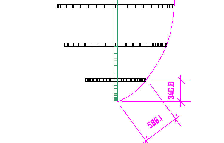
-
Hull Planking Calculator
iMustBeCrazy replied to MintGum's topic in Modeling tools and Workshop Equipment
The 'rib spacing' must always be 'as the plank lays'. At the bow strakes tend to curve out as well as up (to the bow) so adding a millimetre or two (depending on scale) to the first spacing is probably the easiest. It's never going to be perfect so we shouldn't be too pedantic. If the hull is convex we need to add a little to the breadth of the strake to allow for bevelling, if it's straight or concave we don't. This would be difficult as it depends on the strakes location. -
MintGum reacted to a post in a topic:
Hull Planking Calculator
-
iMustBeCrazy reacted to a post in a topic:
Hull Planking Calculator
-
Hull Planking Calculator
iMustBeCrazy replied to MintGum's topic in Modeling tools and Workshop Equipment
The changes look good, everything to scale. That was my due to my misunderstanding of the extend function ( and I'm still not sure about it). Extend doesn't accept a value of zero. Again, this may be me misunderstanding. -
iMustBeCrazy reacted to a post in a topic:
Hull Planking Calculator
-
Hull Planking Calculator
iMustBeCrazy replied to MintGum's topic in Modeling tools and Workshop Equipment
I gave it a try, I think it has potential. On my prints it prints to scale vertically but not horizontally. So the tick strips and the plank widths are good but the strake lengths and rib positions are out, 18mm spacing prints as 21mm. "Extra" seems to add a length to the stern but there is no allowance for the bow, I added an extra 'frame' the same height as frame 1 with the spacing being the distance from the stem and shuffled the frames along so 1 became 2 etc. Some enhancements I'd like to see: Make the print default to landscape. And perhaps a print dialogue that allows you to select pages (I had to print 4 pages for each test when I only needed to print page 3). Add text to the strake printout labelling the bow and/or the frames. Add an 'overlap' option for lapstrake/clinker planking. Anyway, a good start and a thumbs up from me. I'm looking forward to v1.1.0.0. Edit, I forgot to say I'm printing on A4 and proportions and scale are correct when printing from CAD without needing any adjustments. -
iMustBeCrazy reacted to a post in a topic:
Tally Ho by vaddoc - scale 1:12 (maybe) - as rebuilt by Leo
-
iMustBeCrazy reacted to a post in a topic:
HMS Bounty Launch by EvanKeel - Model Shipways - 1:16
-
iMustBeCrazy reacted to a post in a topic:
HMS Bounty Launch by builder_Nick - Model Shipways - 1:16
-
iMustBeCrazy reacted to a post in a topic:
HMS Bounty Launch by builder_Nick - Model Shipways - 1:16
-
iMustBeCrazy reacted to a post in a topic:
HMS Bounty Launch by builder_Nick - Model Shipways - 1:16
-
iMustBeCrazy reacted to a post in a topic:
HMS Bounty Launch by builder_Nick - Model Shipways - 1:16
-
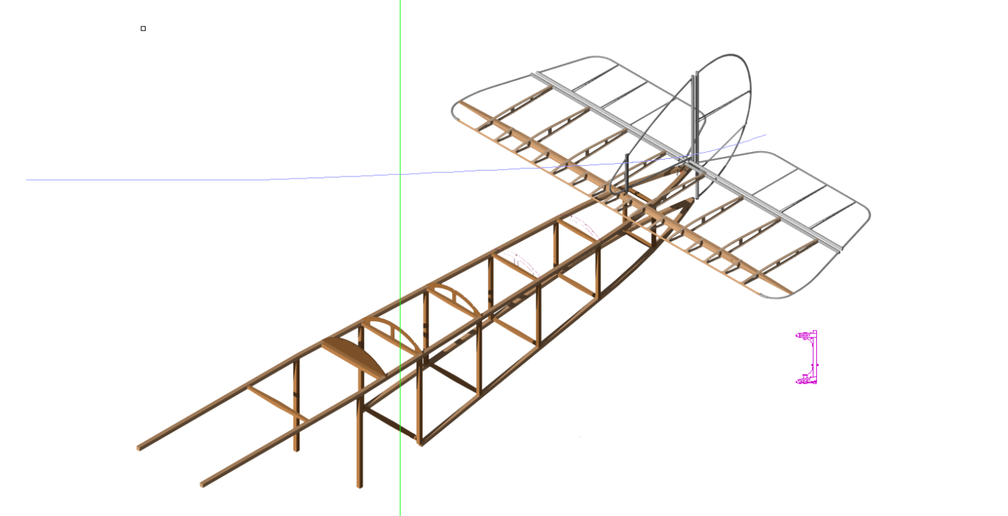
A little further along with the 'Pup'. And there's a lot of detail you can't see in the above. But nowhere near finished.
-
It's more confusing and goes further than just that. 1913 saw the 'Tabloid' which was sometimes known as the 'Scout'. 1914 saw the 'Sea Scout' for the Schneider Trophy. 1915 saw the 'Two Seater Scout'. 1916 sees the Pup, officially the 'Scout' according to most books BUT as the original drawings just call it the '80hp le Rhone' I suspect the real official designation was the '80hp le Rhone Scout'. It appears that it was only after service personnel started calling it the Pup that Sopwith actually started really naming their aircraft.
-
A friend of Dad's had one of those, you still have to make the first one though.
-
When you stop learning, you're dead. Sun went down about an hour ago, it's now 10.7°C which is a little warmer than it's been at this time most nights recently. It's either been a cold (for Melbourne) winter or I'm just feeling it more.
-
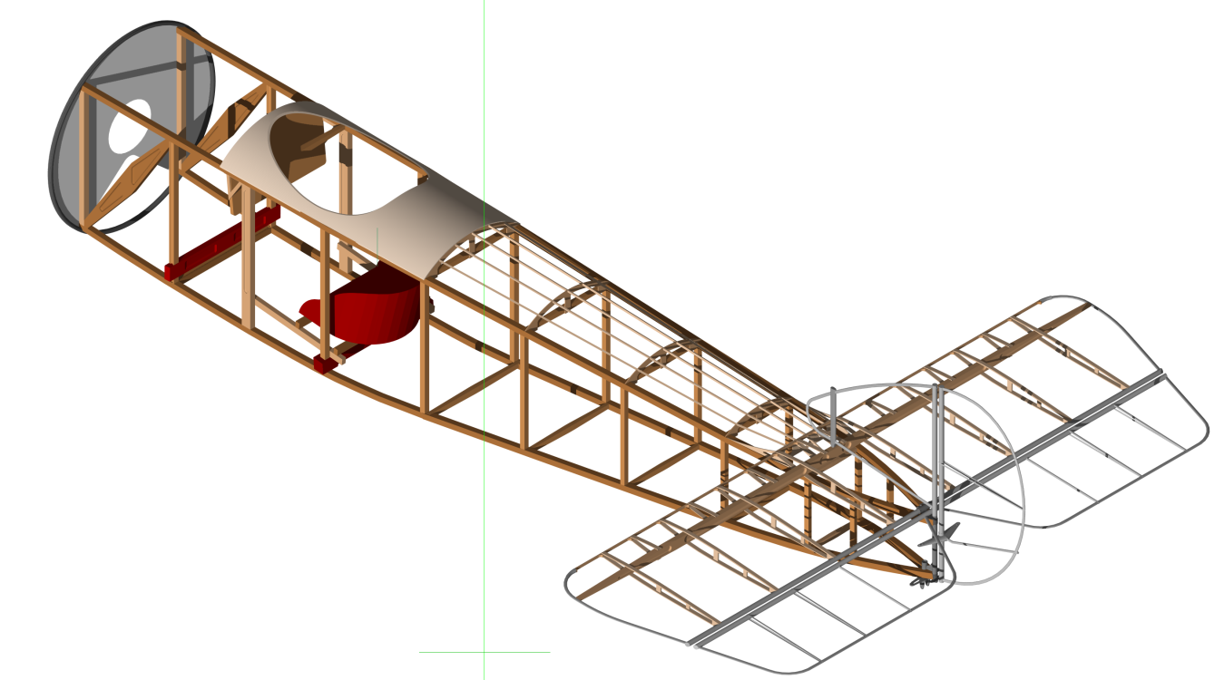
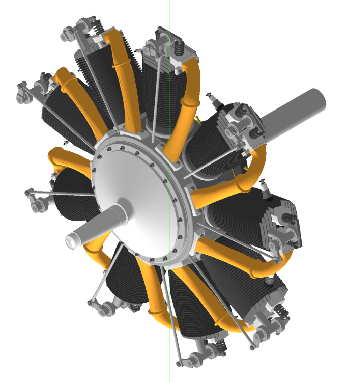
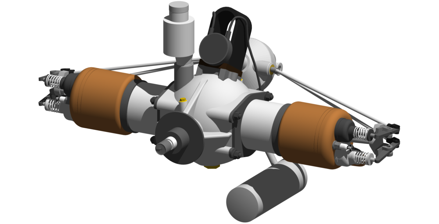
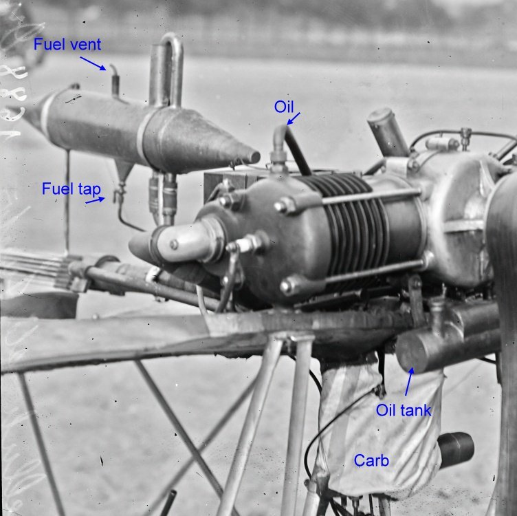
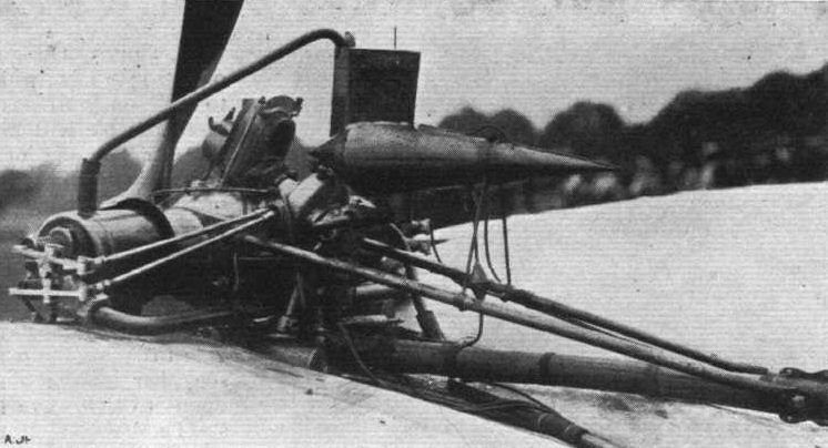
G'day Tim, I hadn't seen it before. I'm guessing 3/4 scale with about twice the hp Alberto had. I've been playing with something else: That's a 80hp Le Rhone 9c rotary (that means the whole engine spins around the crankshaft) that powered many WW1 aircraft. Such as: The Sopwith Scout (nicknamed the Pup) 1916. Or it will be when I finish. But then I think I'll modify it to a Sopwith Dove, largely a post war Pup two seater. Or at least inspired by the Pup with three more years of development. Eventually I'll make a 1/8th model of either a Pup or a Dove. Meanwhile I'm learning more about CAD, including why those last two formers on the Pup above don't look solid (I had the same problem on the Lapwing drawing). But the Prop is still kicking my backside.
-
I would continue as you are but glue some 400 grit sandpaper to the back of the ruler and use several light cuts.
-
Not much to show this time, just push rods and a bit of tidying up. I got distracted trying to draw a prop for it and that's proved to be problematic, I see a way forward but it's going to be a pain. Still outstanding on the engine are a carburettor, oil lines, cooling system and extra flanges and bolts.
-
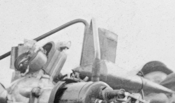
On the 20, yes (brain fade) the big one behind the pilot seat is fuel. But on the 19 there should be no coolant so it looks like he's using the fuel tank as an oil cooler or he's using the oil to heat the fuel (the oil tank in front of the engine would also act as an oil cooler). The piping appears to pass through the fuel tank. I don't know if there was a problem with something like wax in early fuels but I can't imagine why you would heat your fuel to the point it starts boiling off. 😟 On the 20, you're right, it's a coolant header tank. I assume it's unpressurised so the 'conning tower' out the top is to allow steam to condense and/or water to settle or perhaps not slop out when turning?

- 288 replies
-
- 3
-
-
- Santos Dumont No. 18
- hydroplane
- (and 1 more)


