Henriy
-
Posts
17 -
Joined
-
Last visited
4 Followers


-
 J11 reacted to a post in a topic:
USS Constitution by Henriy - Model Shipways Kit 2040 - Scale 1/76
J11 reacted to a post in a topic:
USS Constitution by Henriy - Model Shipways Kit 2040 - Scale 1/76
-
J11 reacted to a post in a topic:
USS Constitution by Henriy - Model Shipways Kit 2040 - Scale 1/76
-
Unegawahya reacted to a post in a topic:
USS Constitution by Henriy - Model Shipways Kit 2040 - Scale 1/76
-
GrandpaPhil reacted to a post in a topic:
USS Constitution by Henriy - Model Shipways Kit 2040 - Scale 1/76
-
JeffT reacted to a post in a topic:
USS Constitution by Henriy - Model Shipways Kit 2040 - Scale 1/76
-
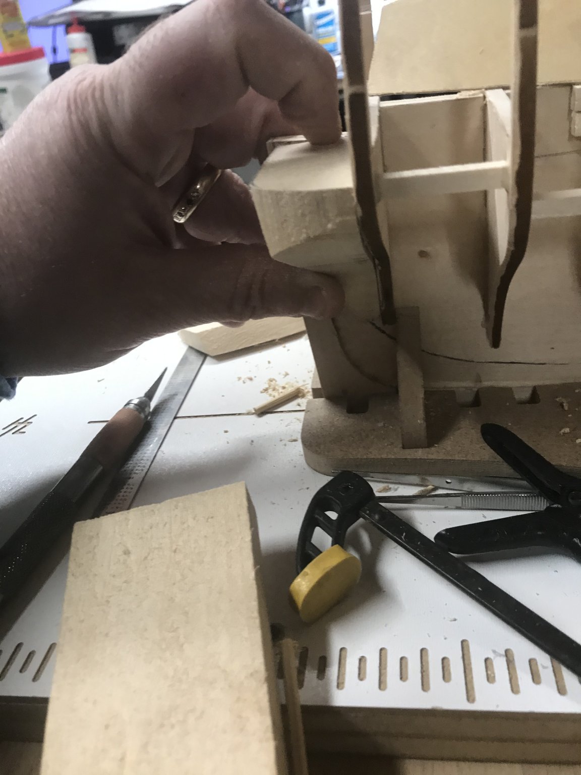
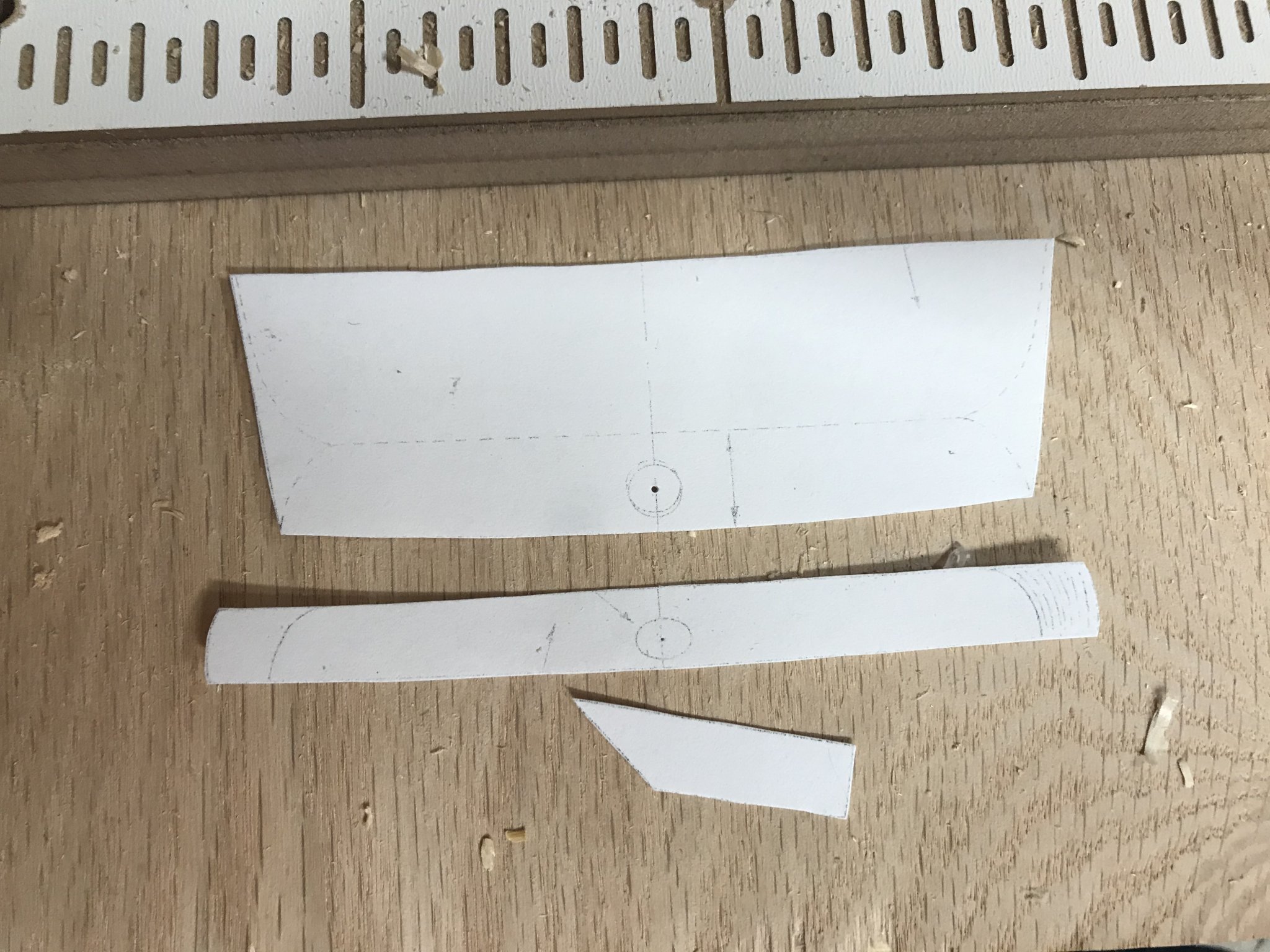
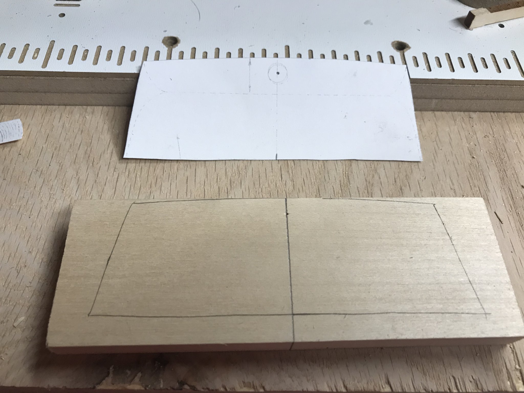
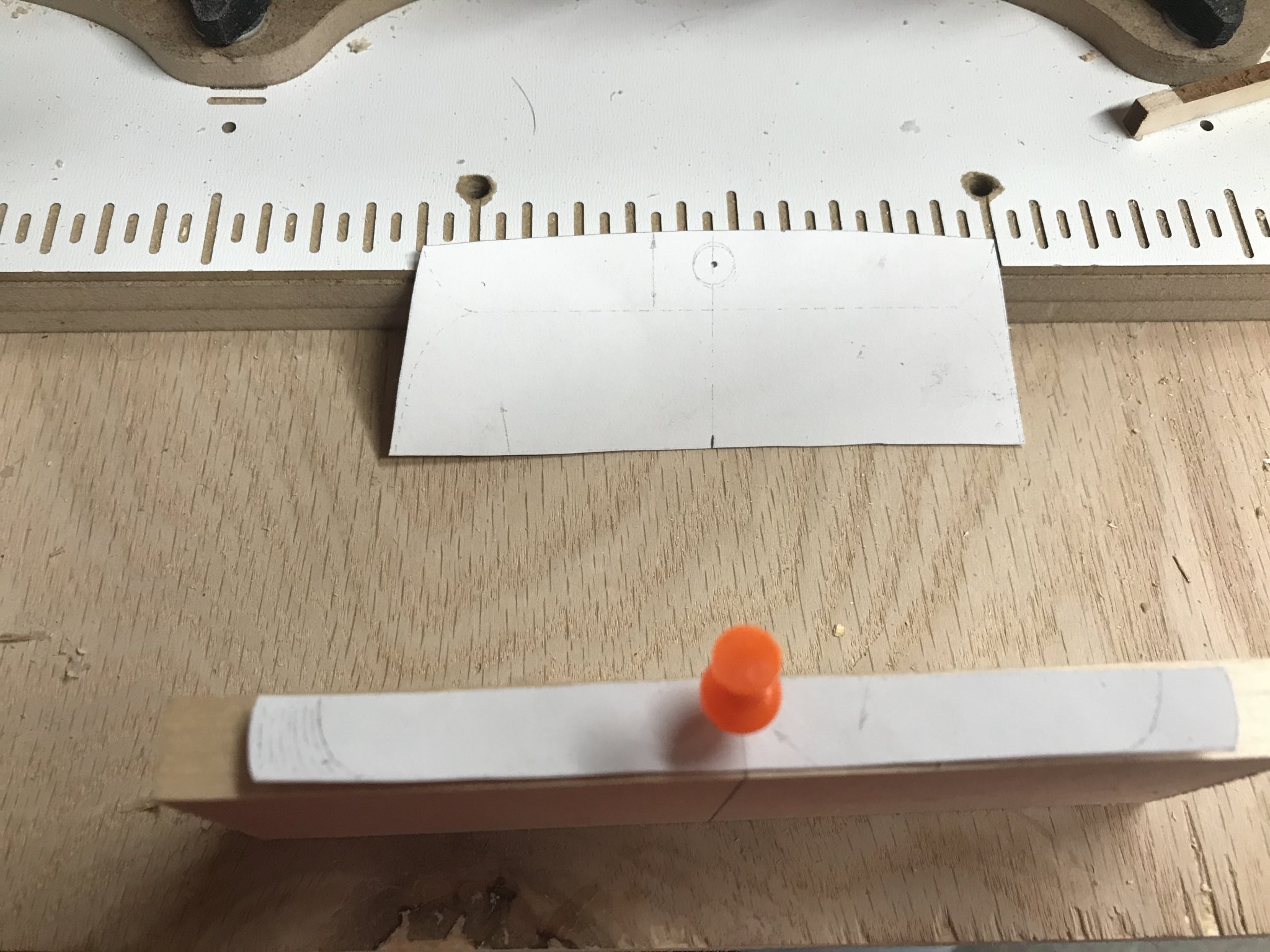
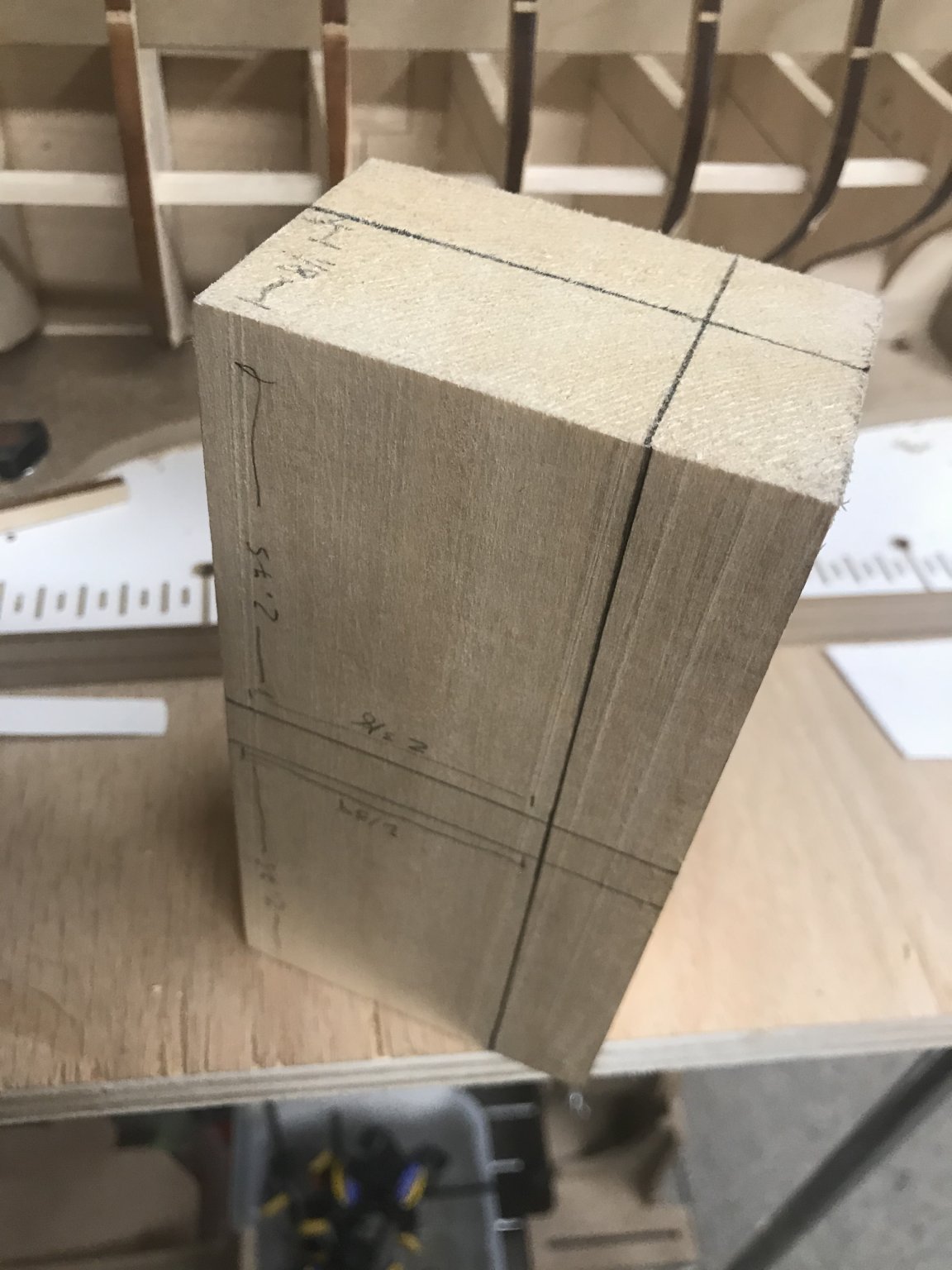
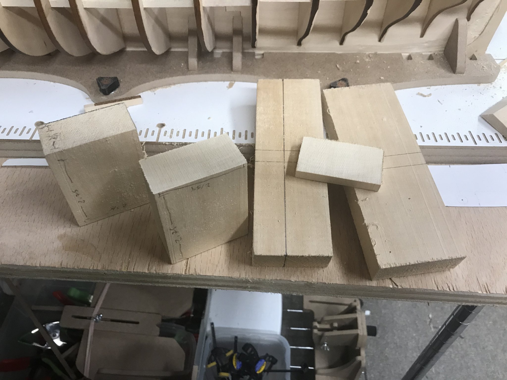
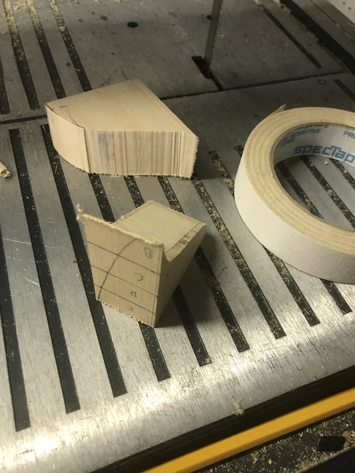
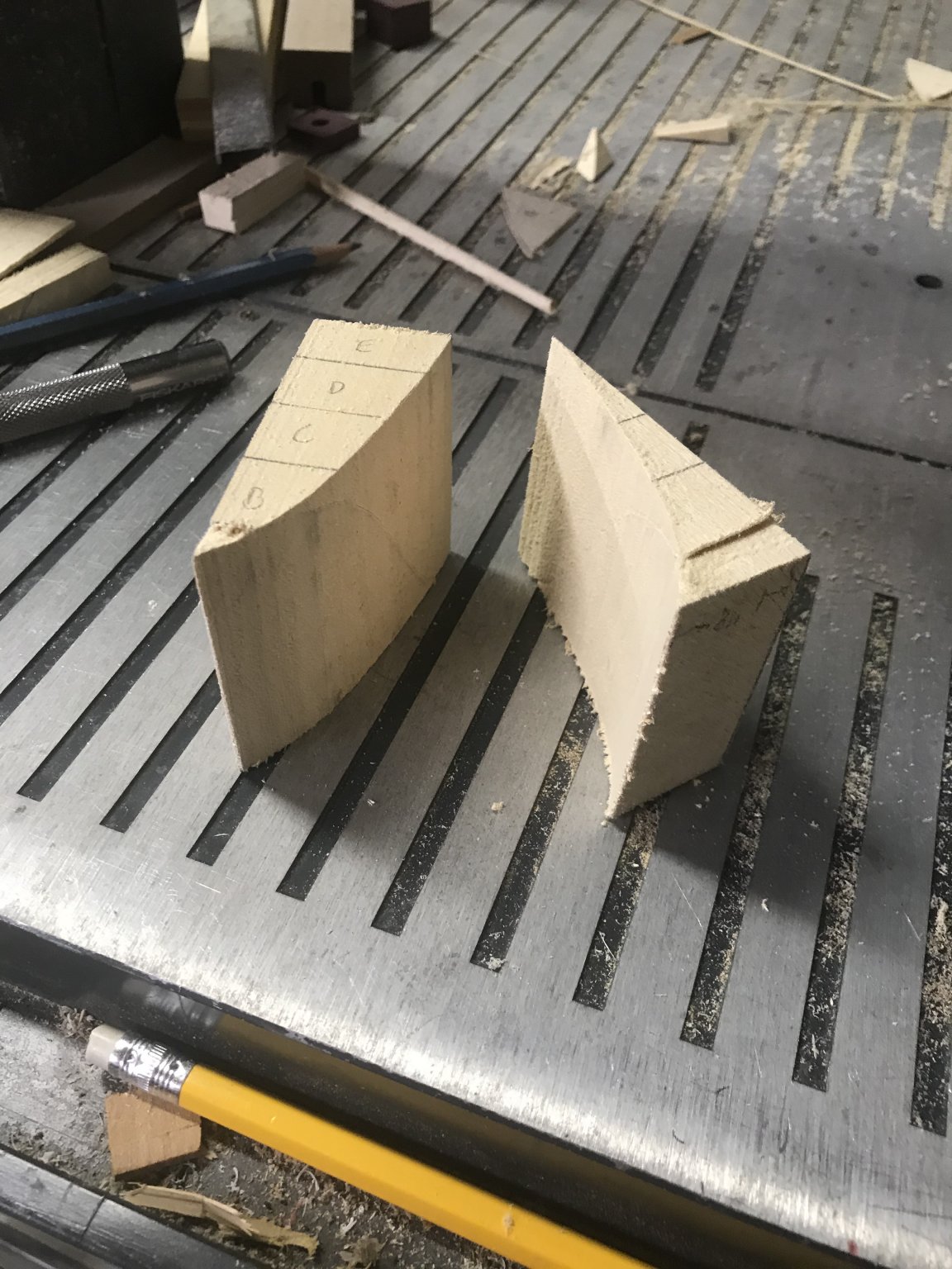
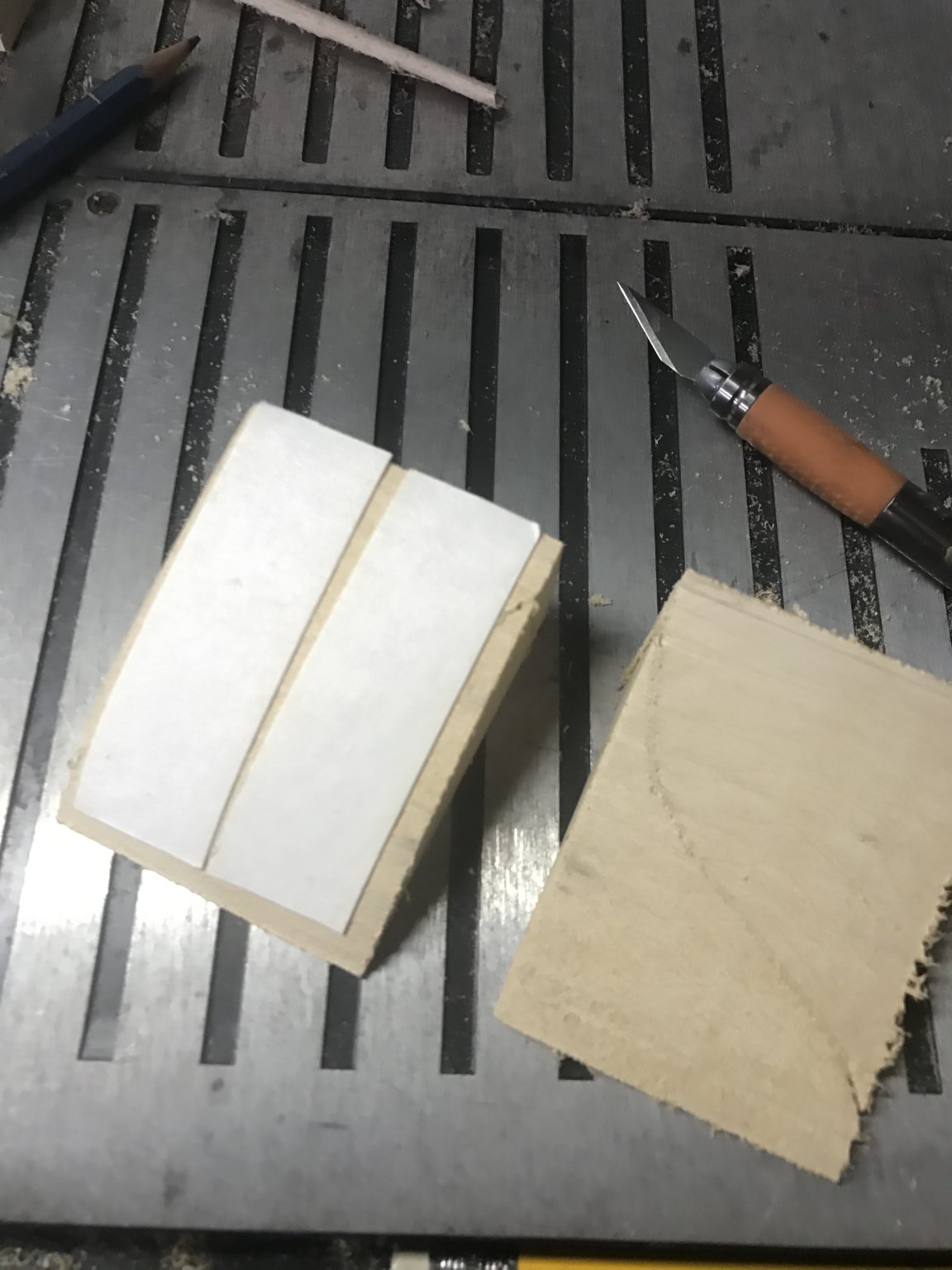
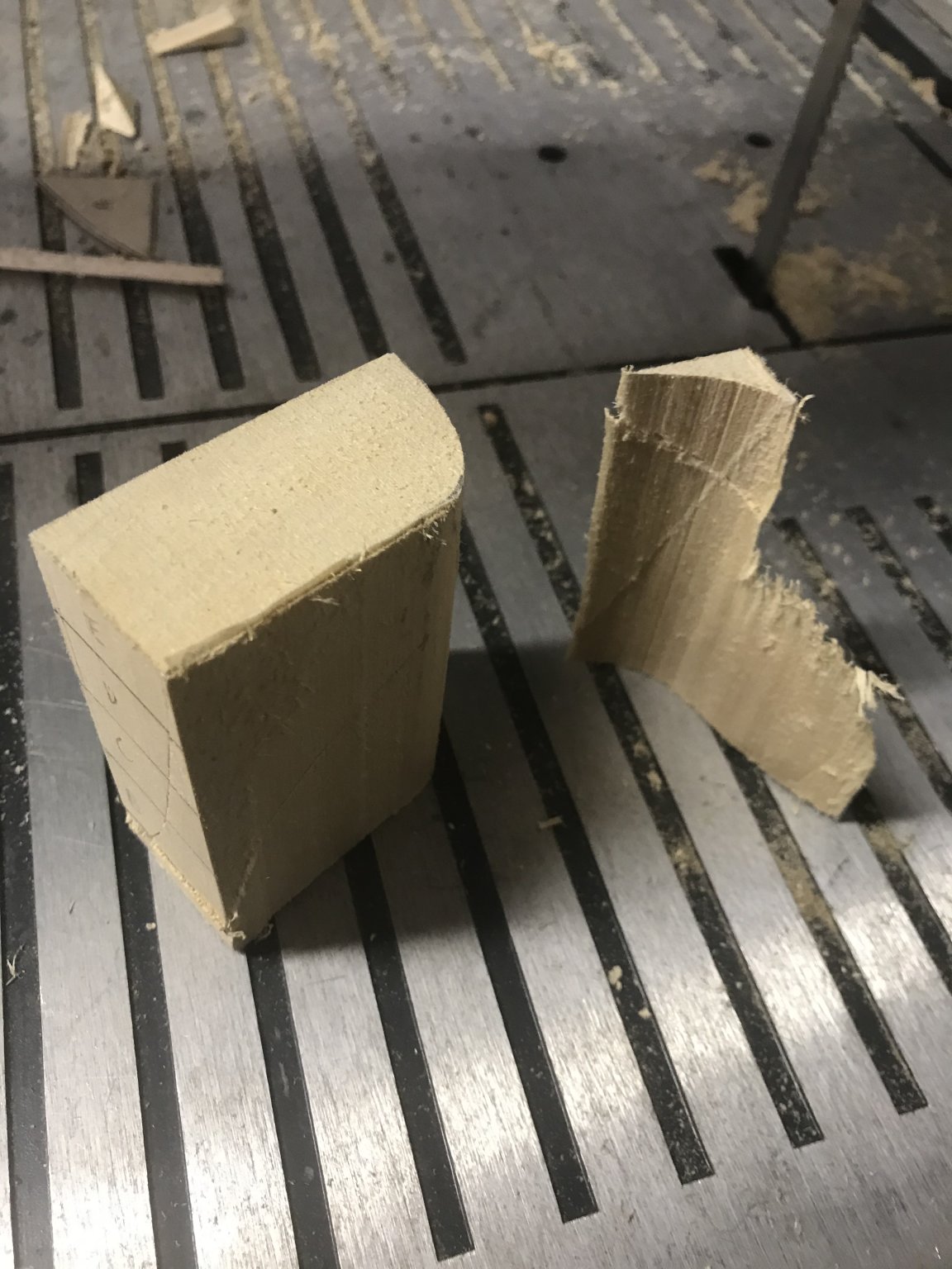
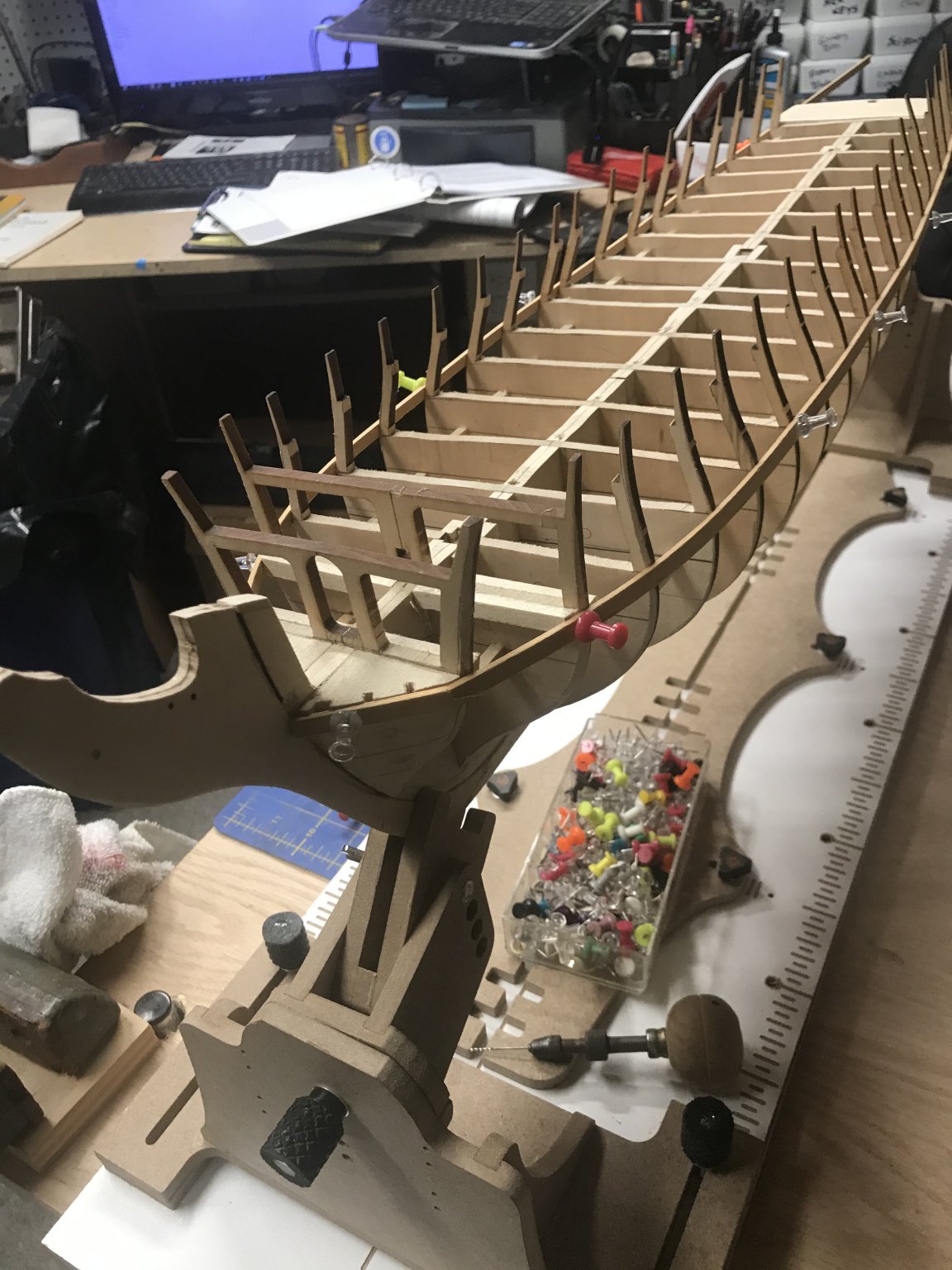
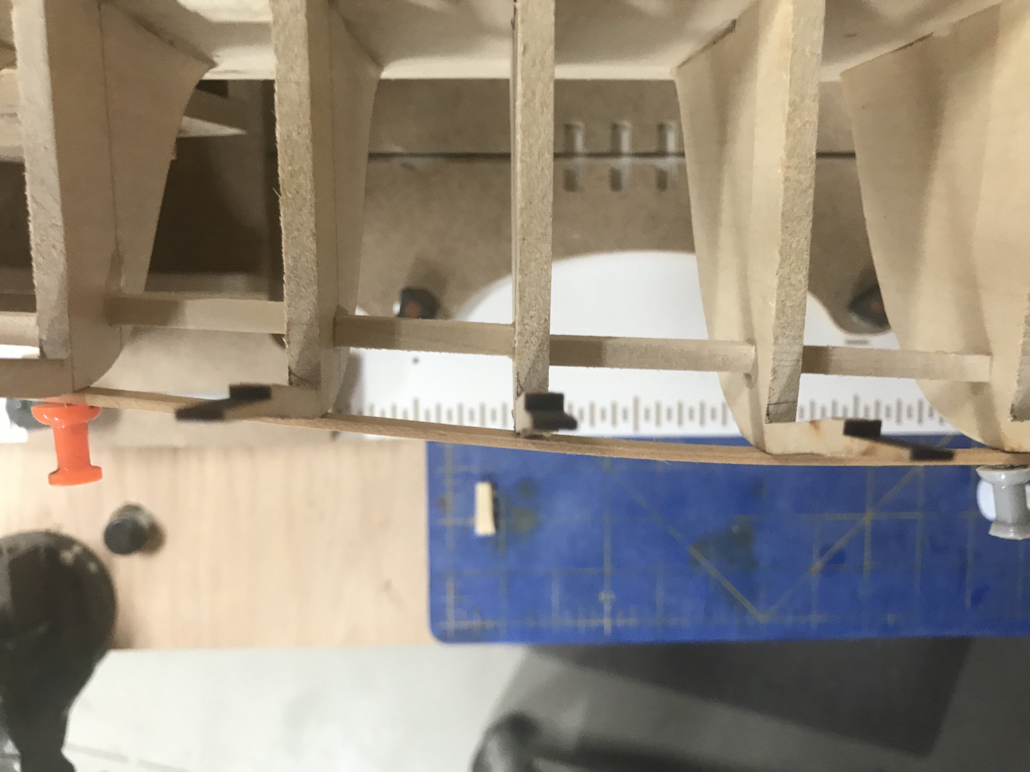
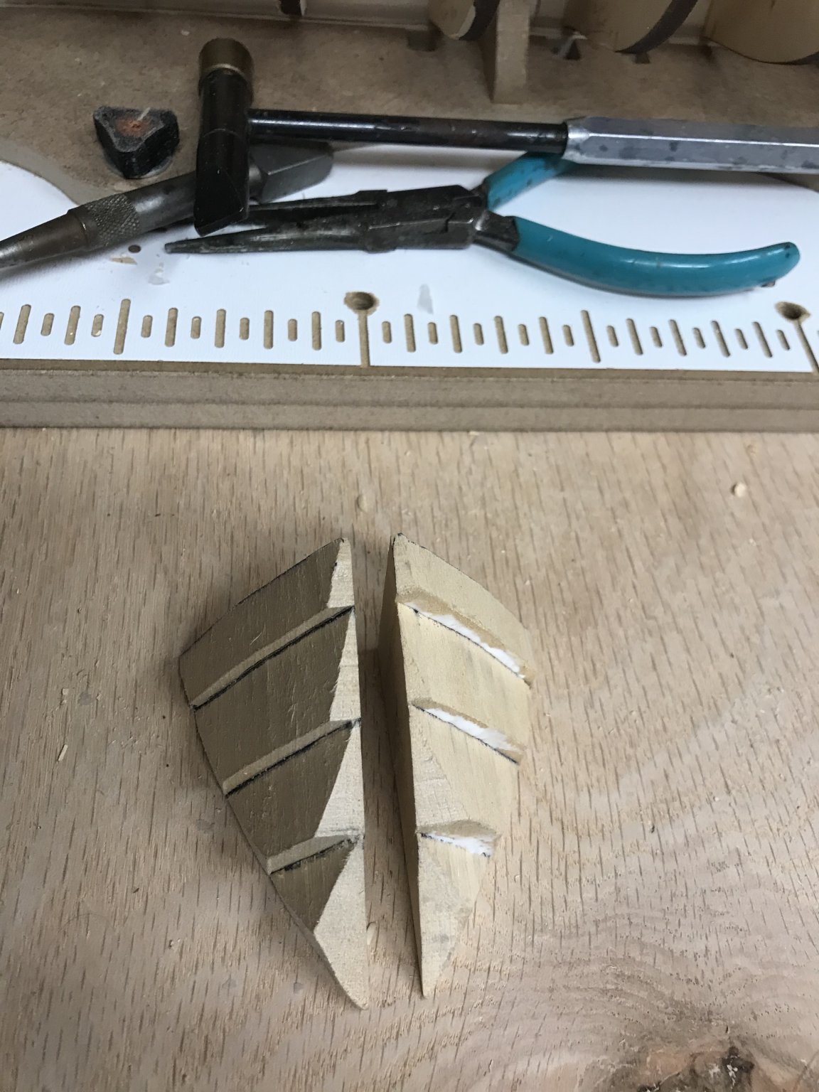
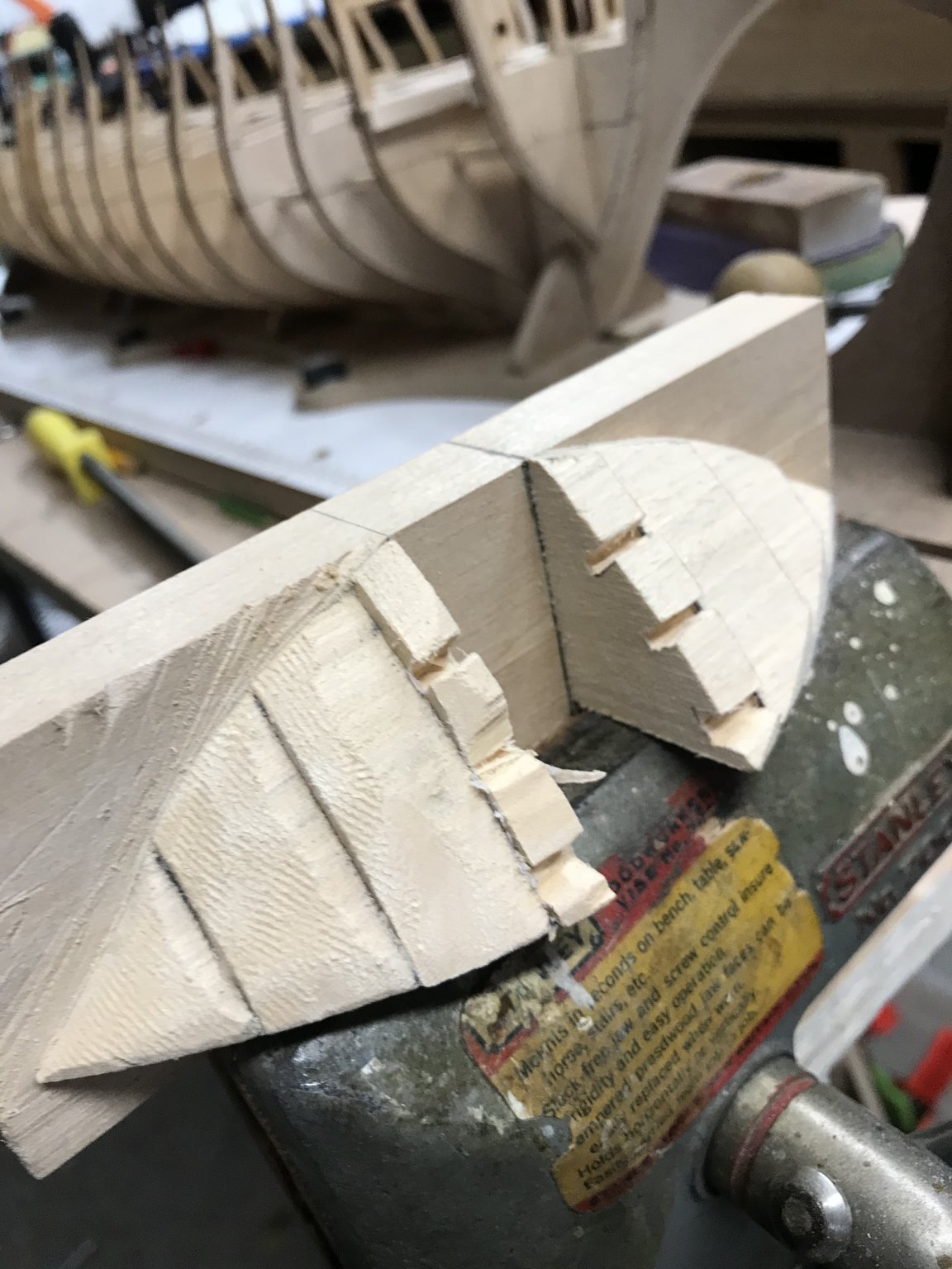
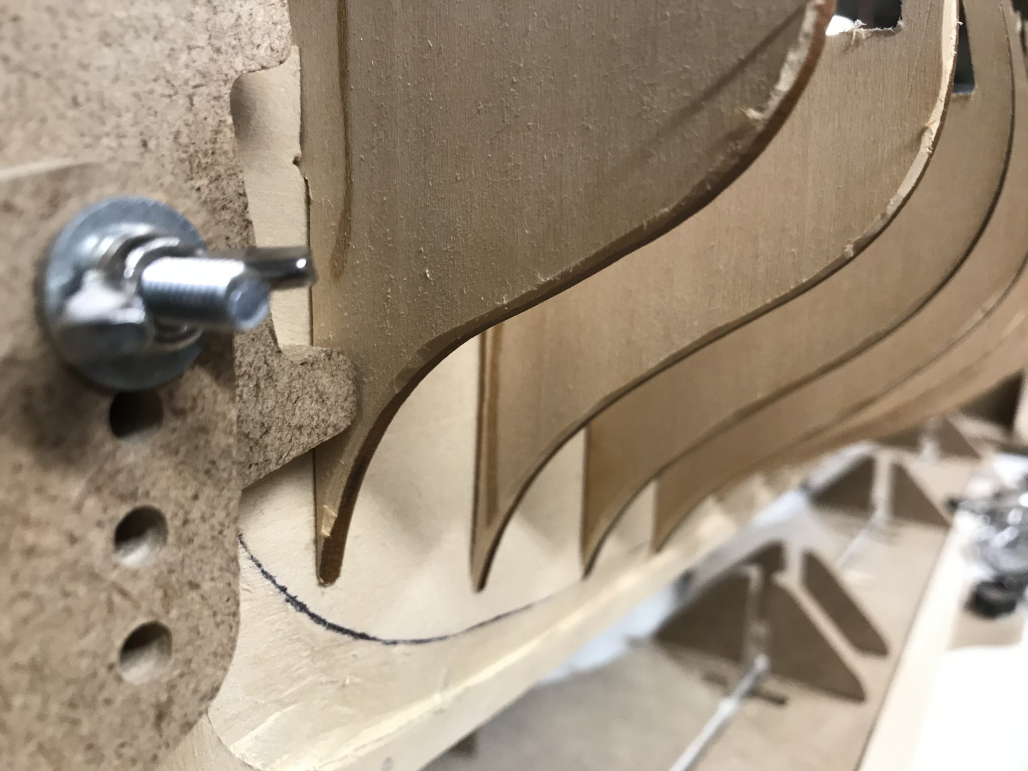
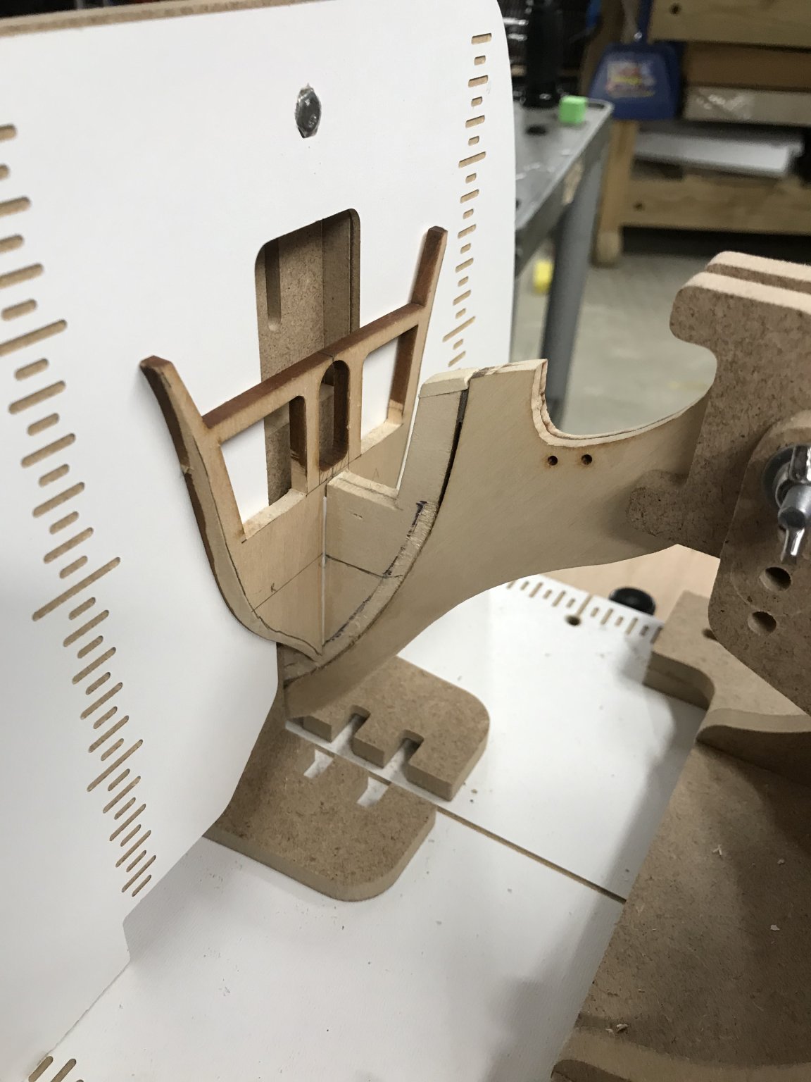
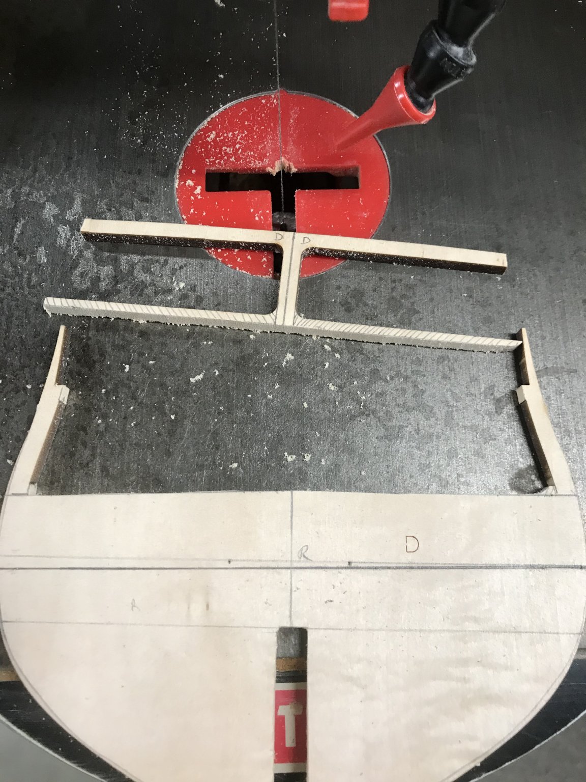
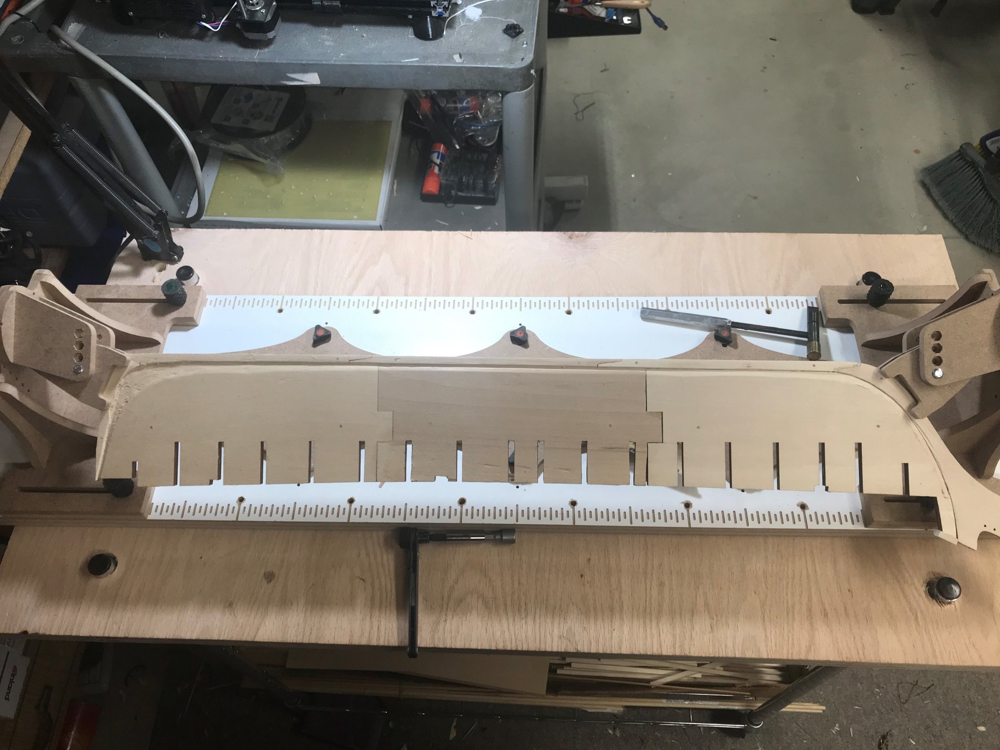
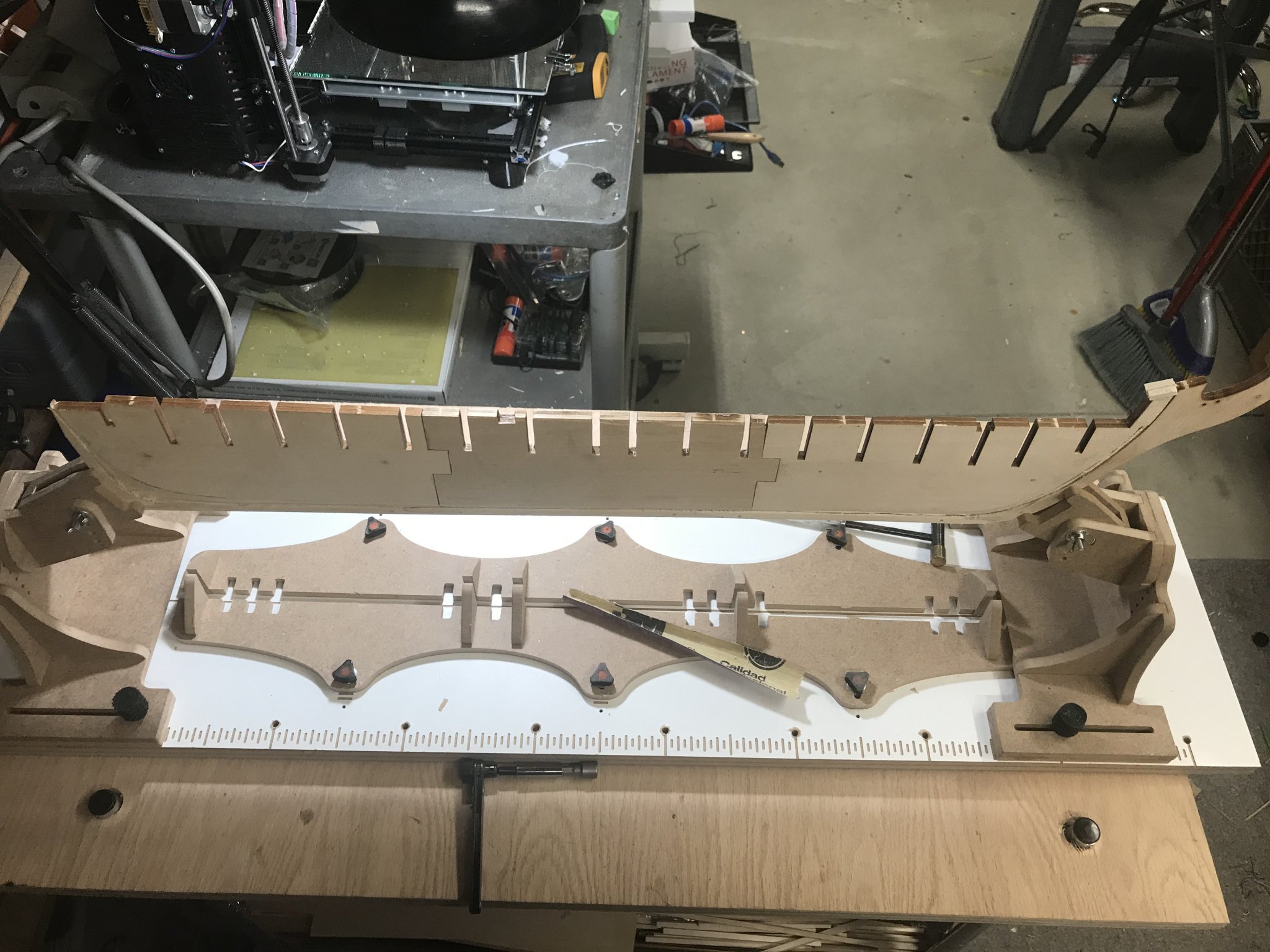
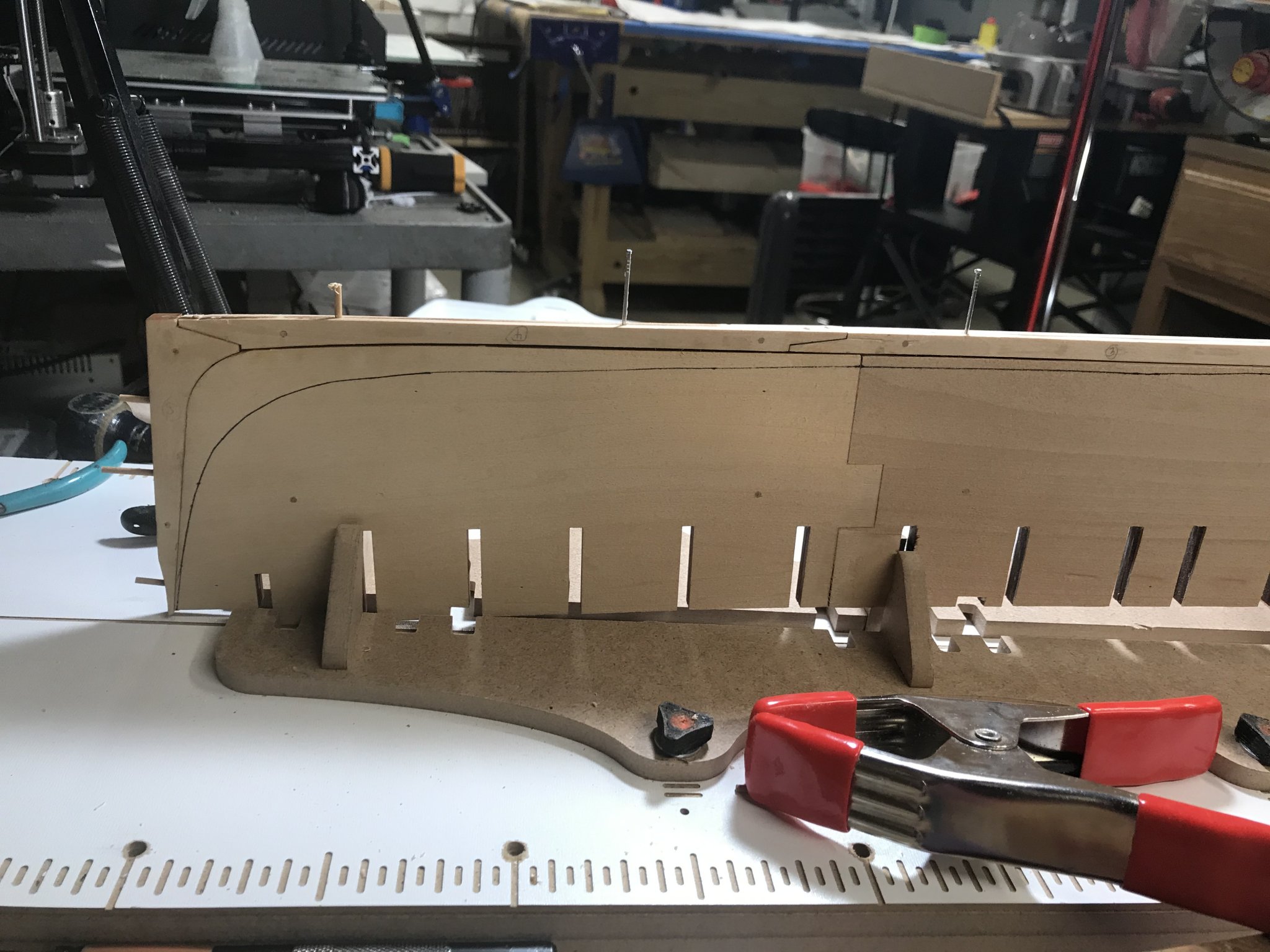
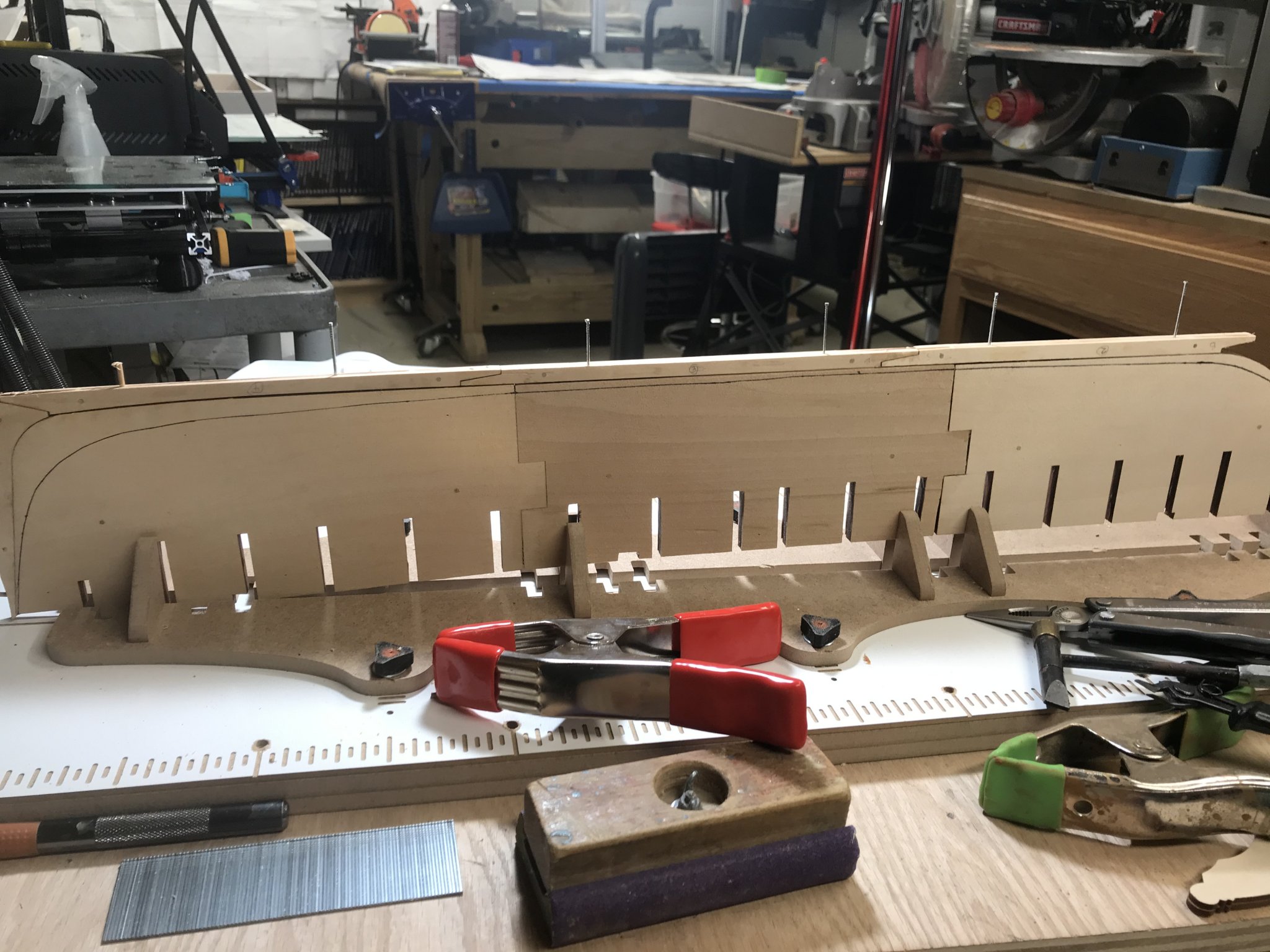
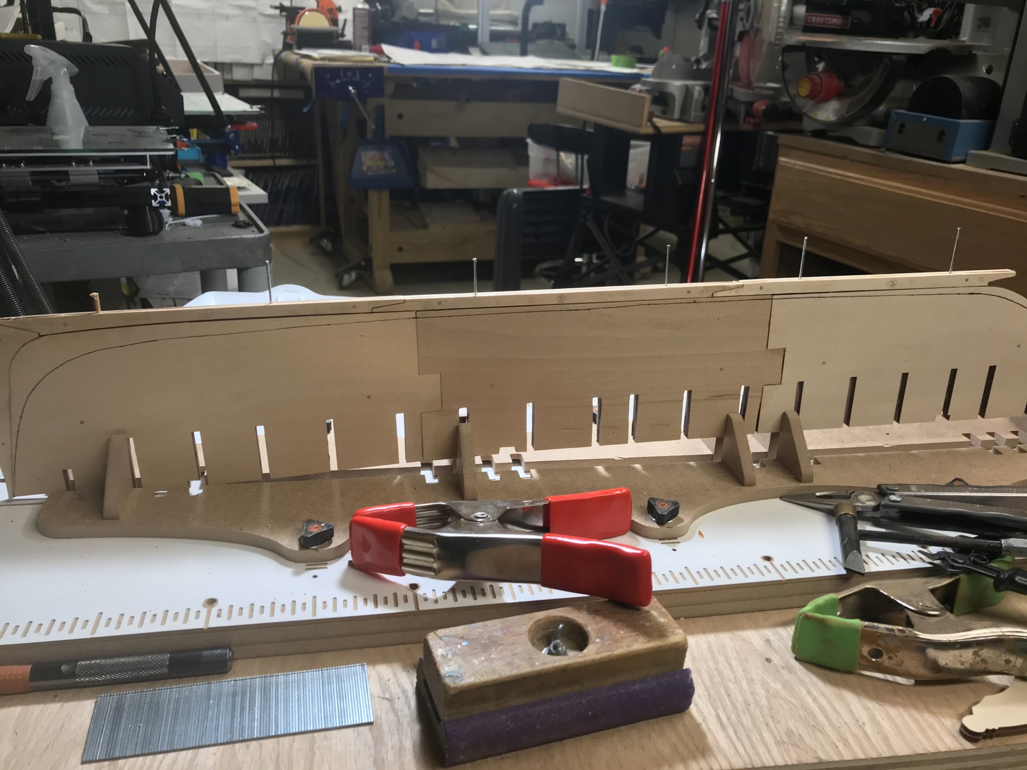
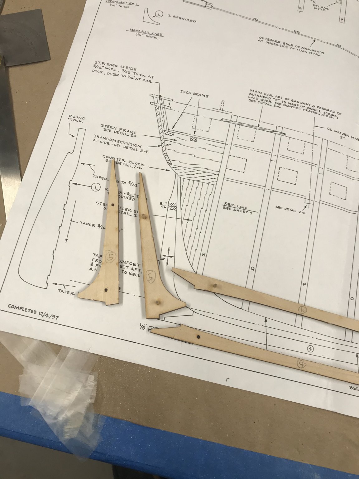
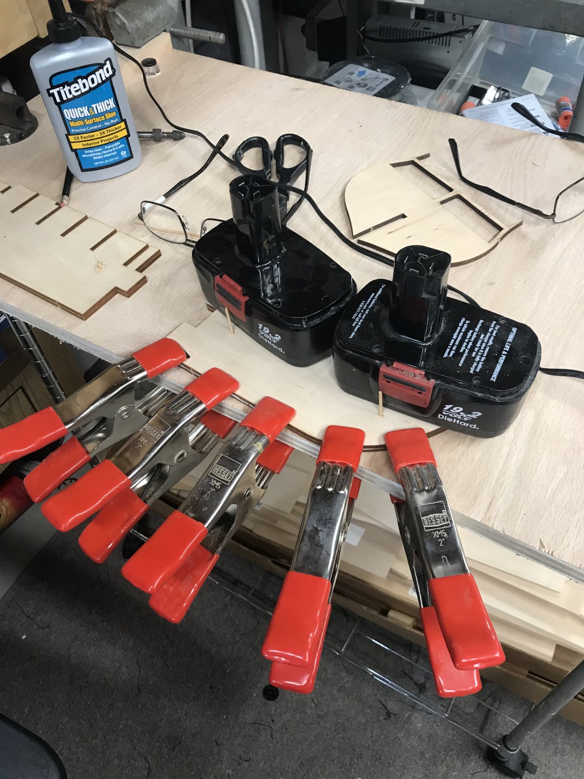
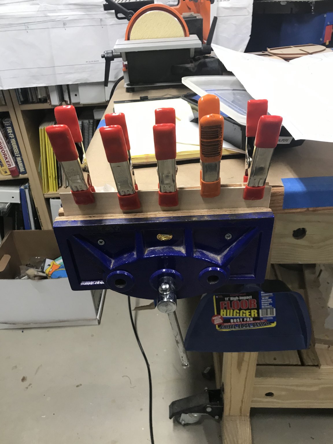
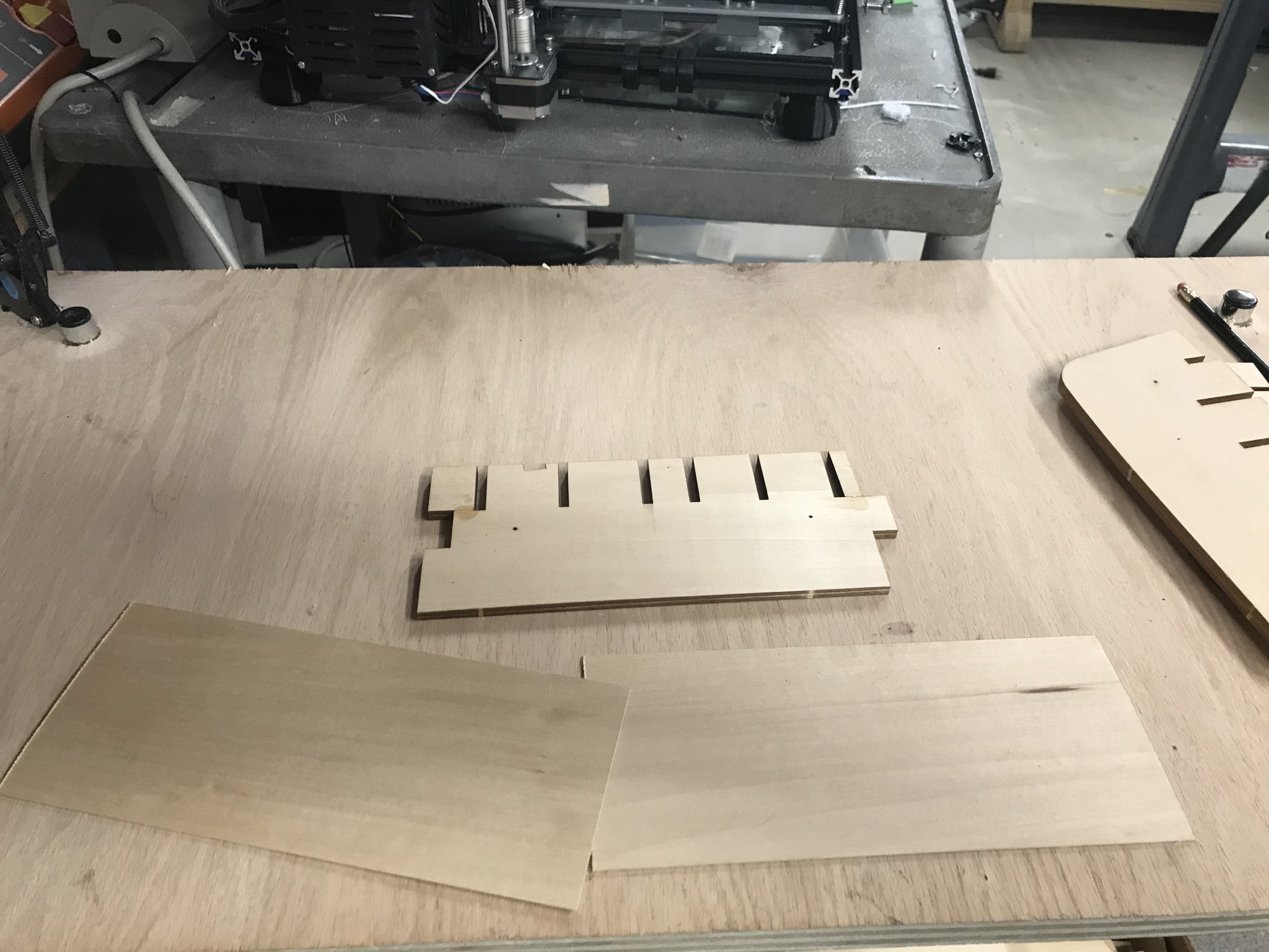
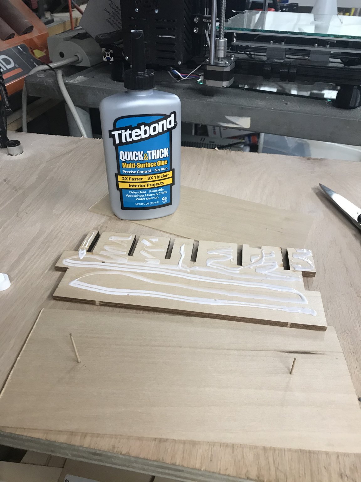
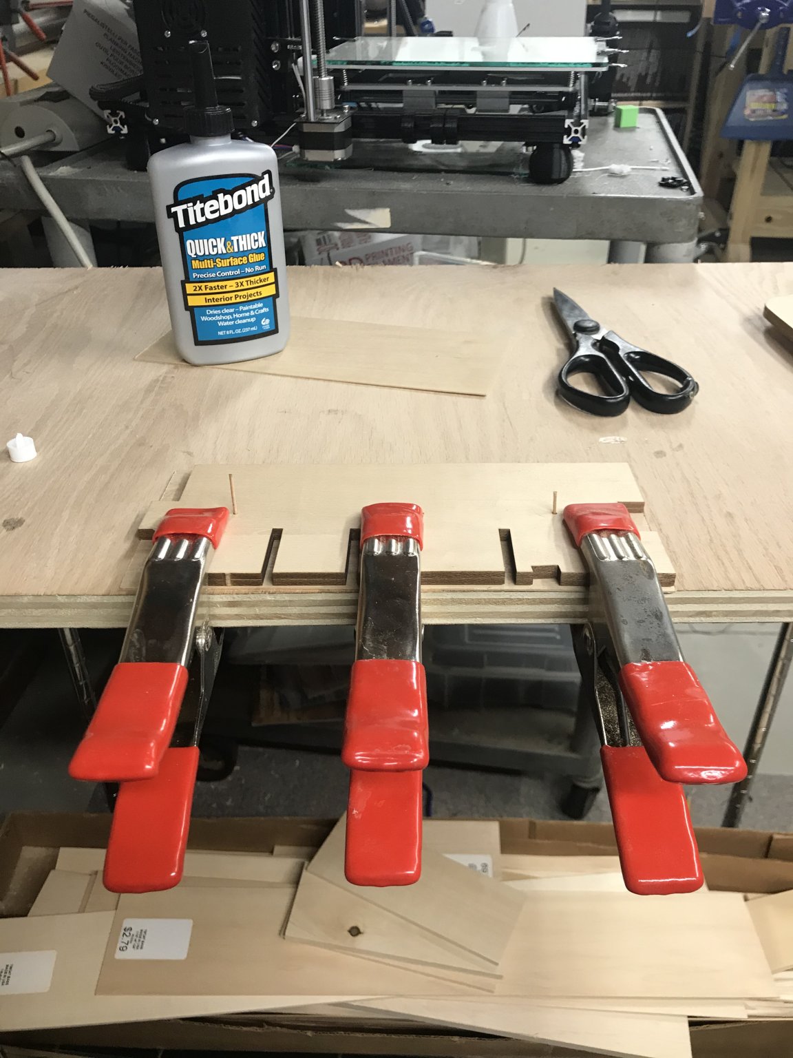
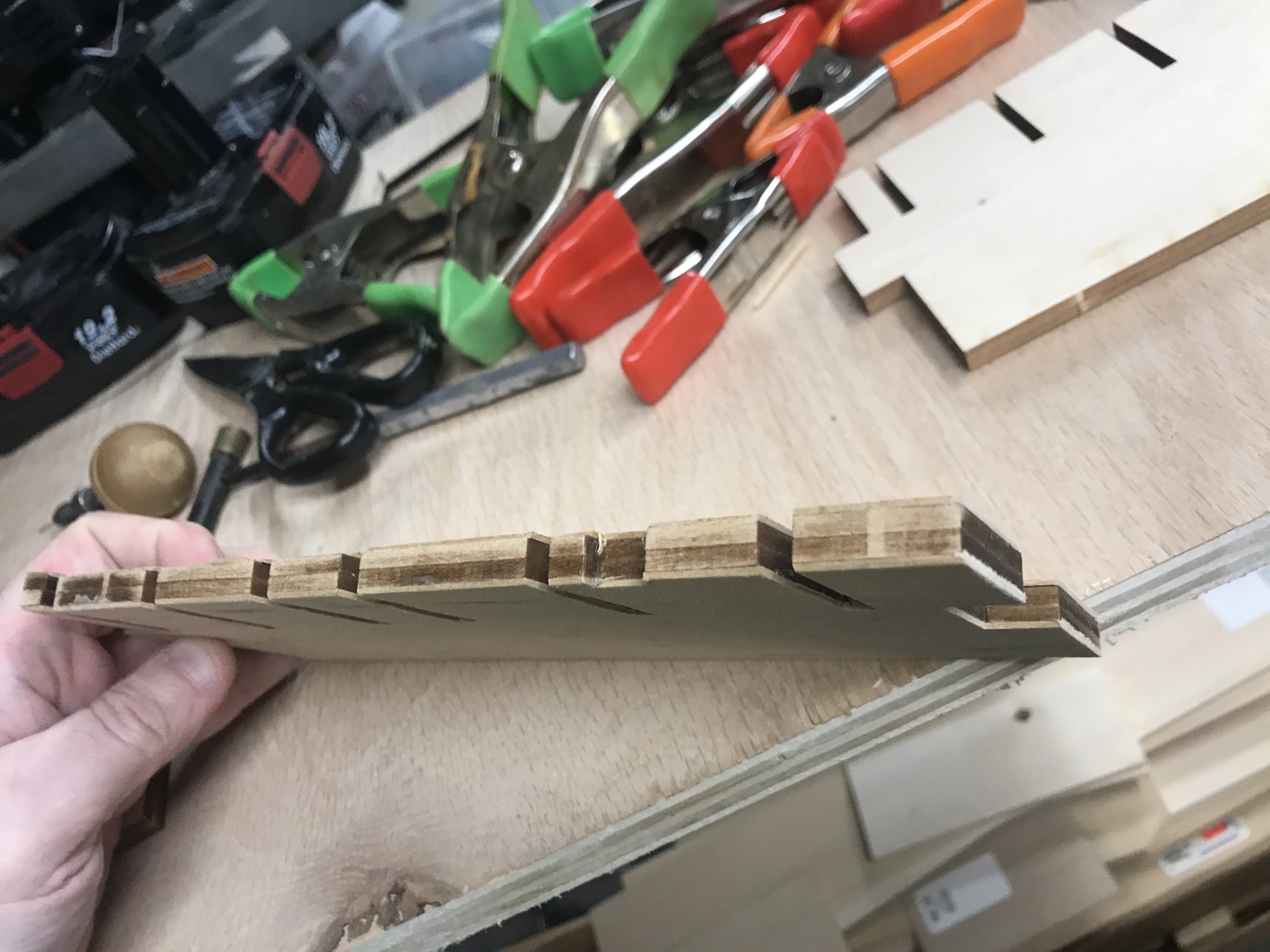
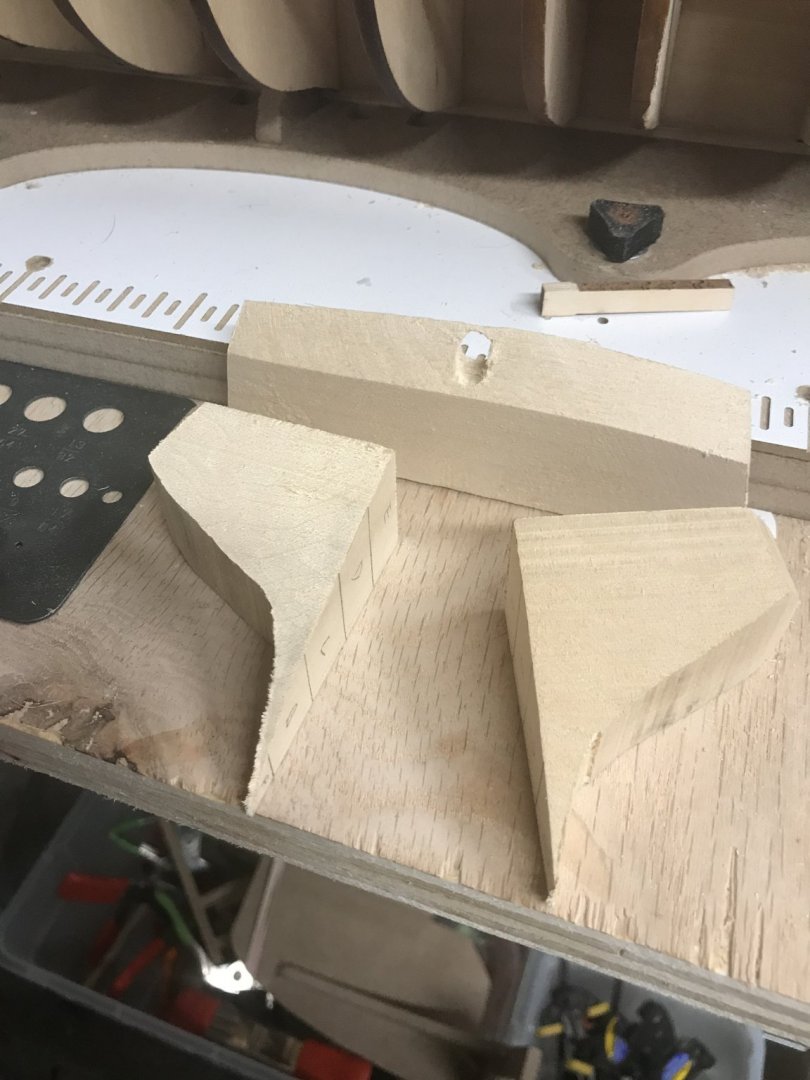
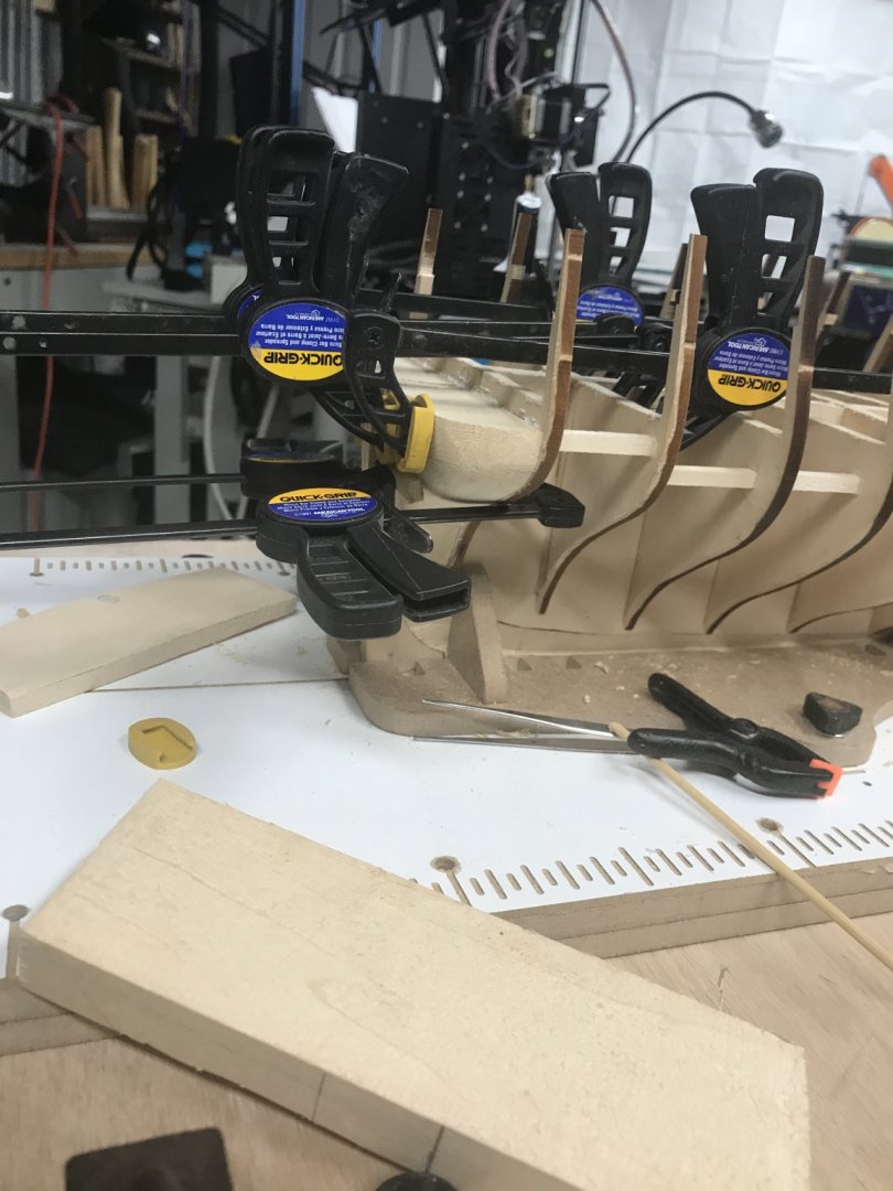
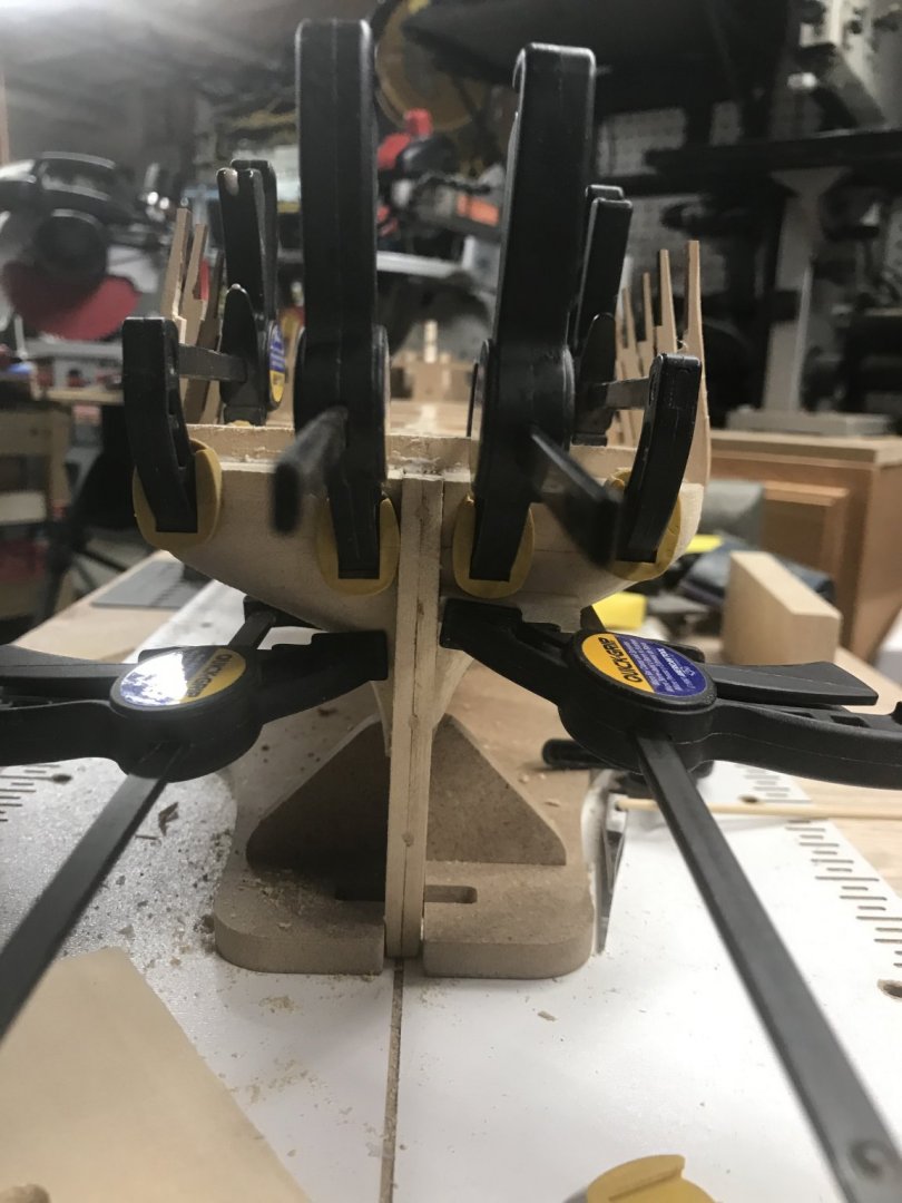
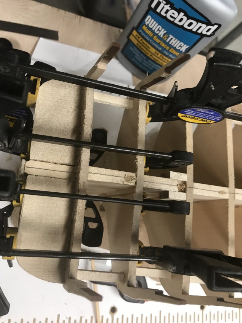
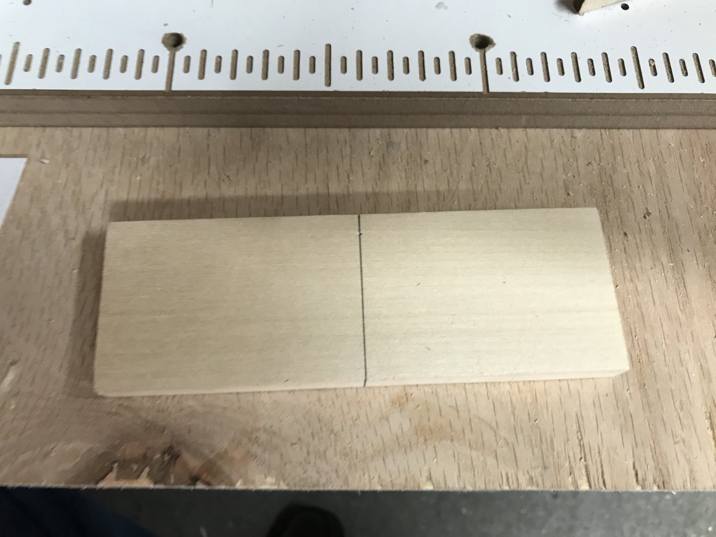
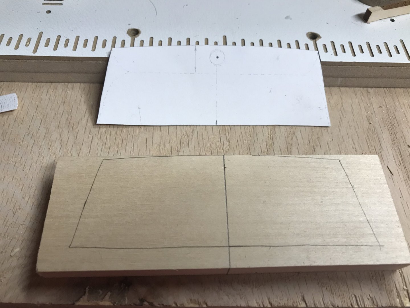
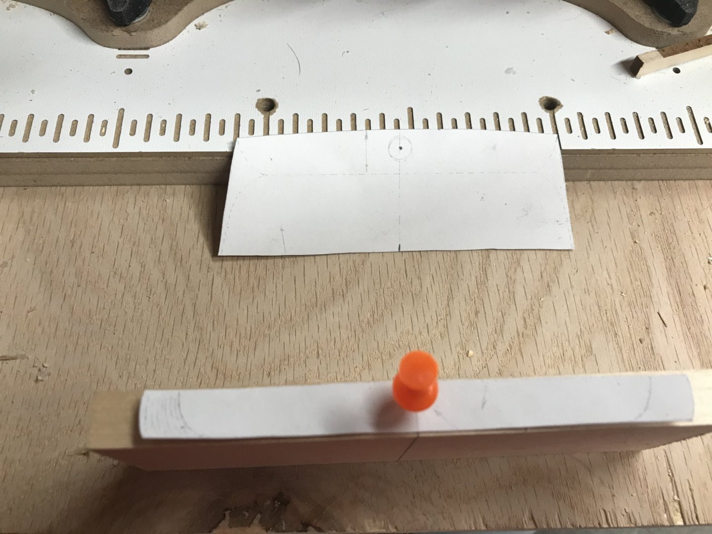
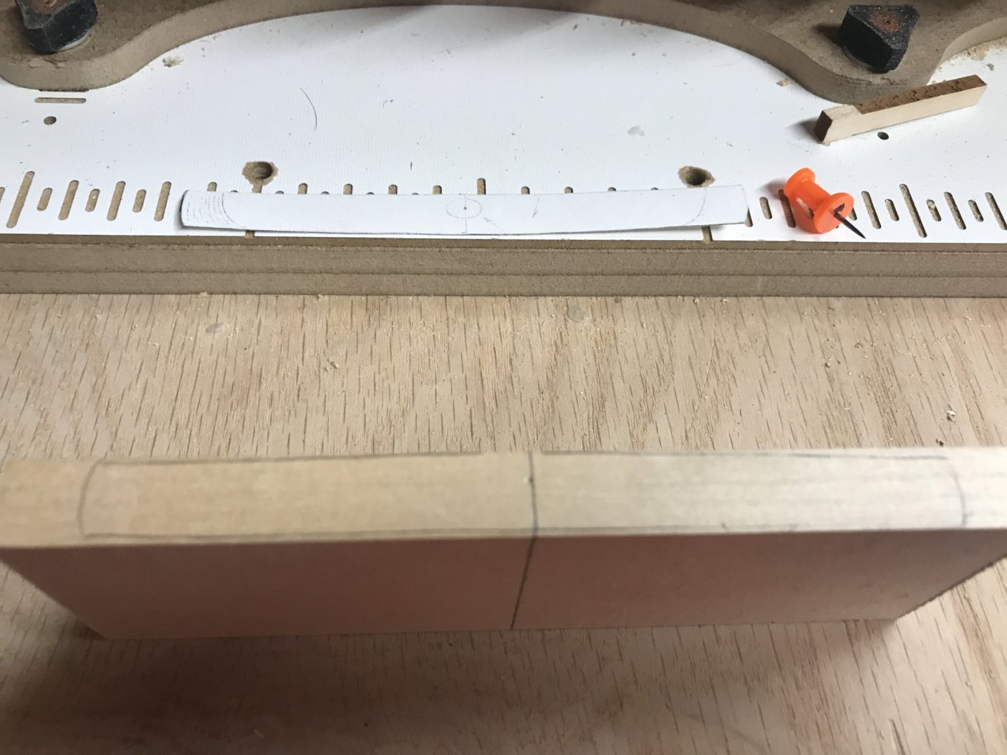
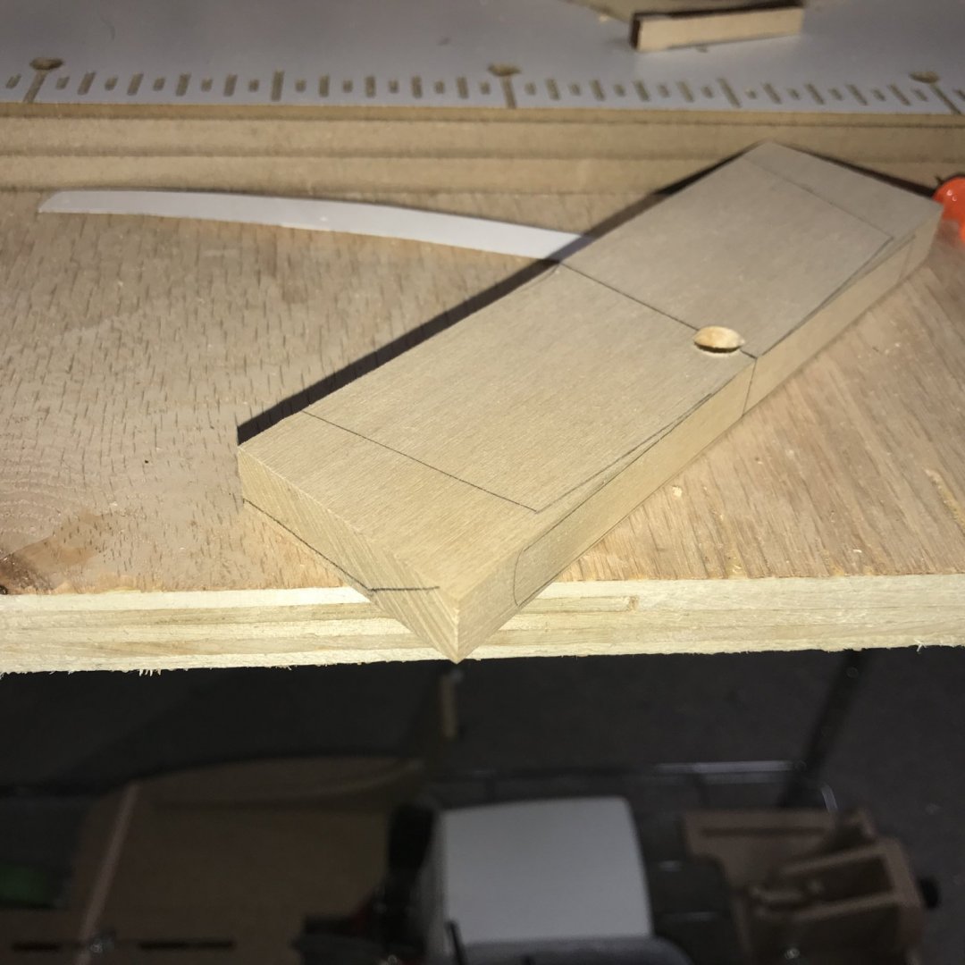
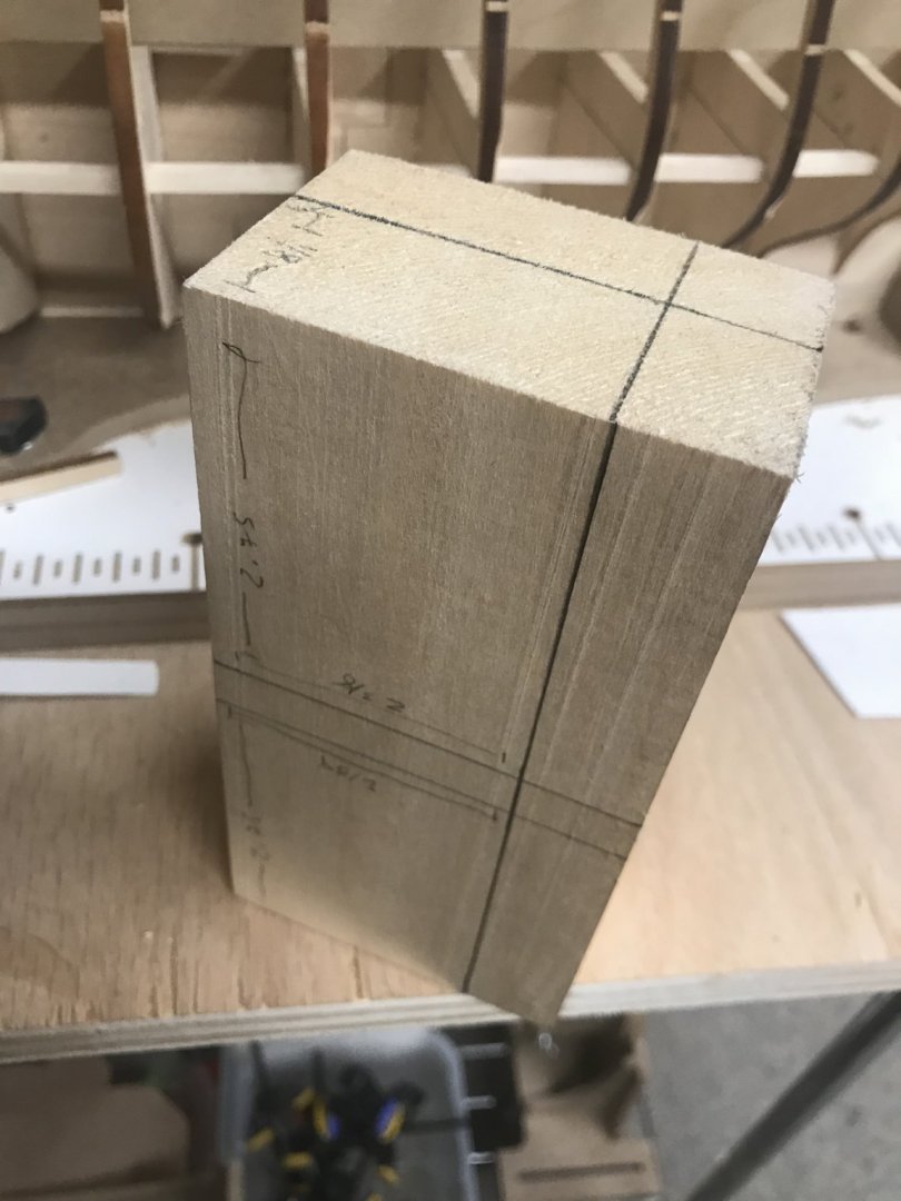
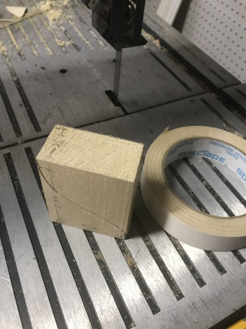
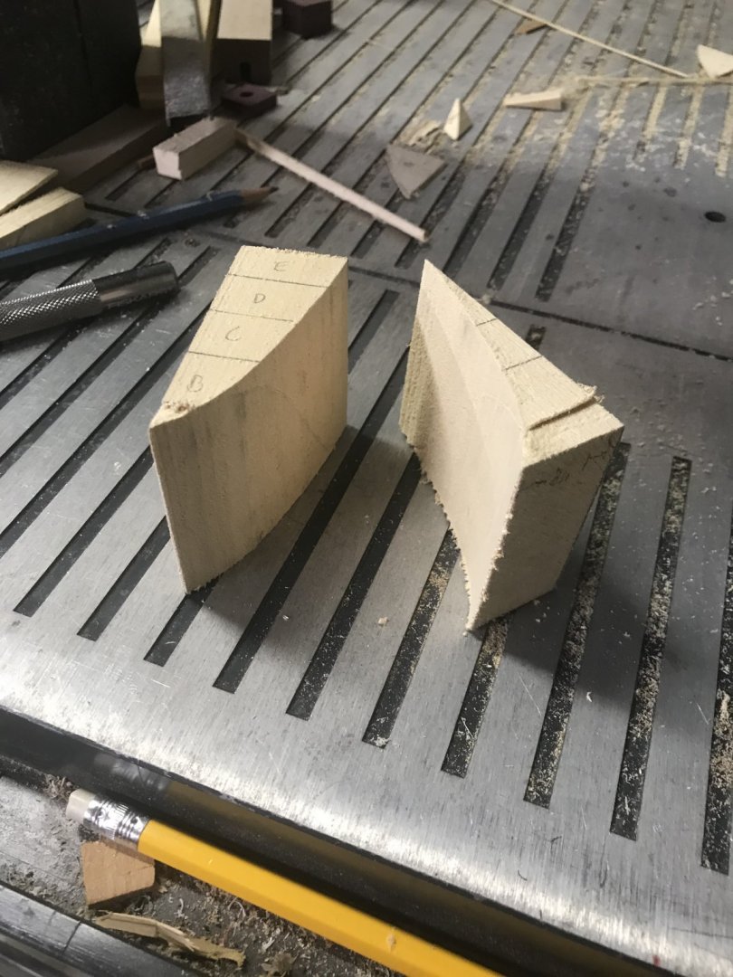
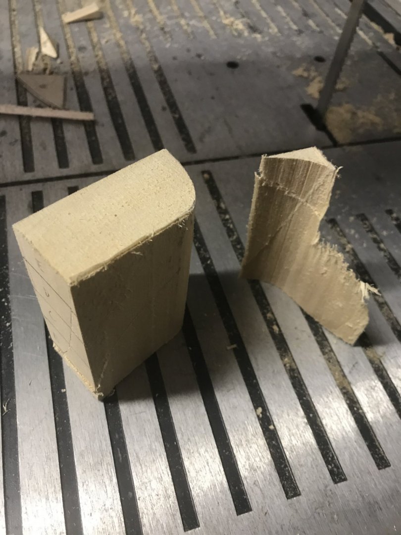
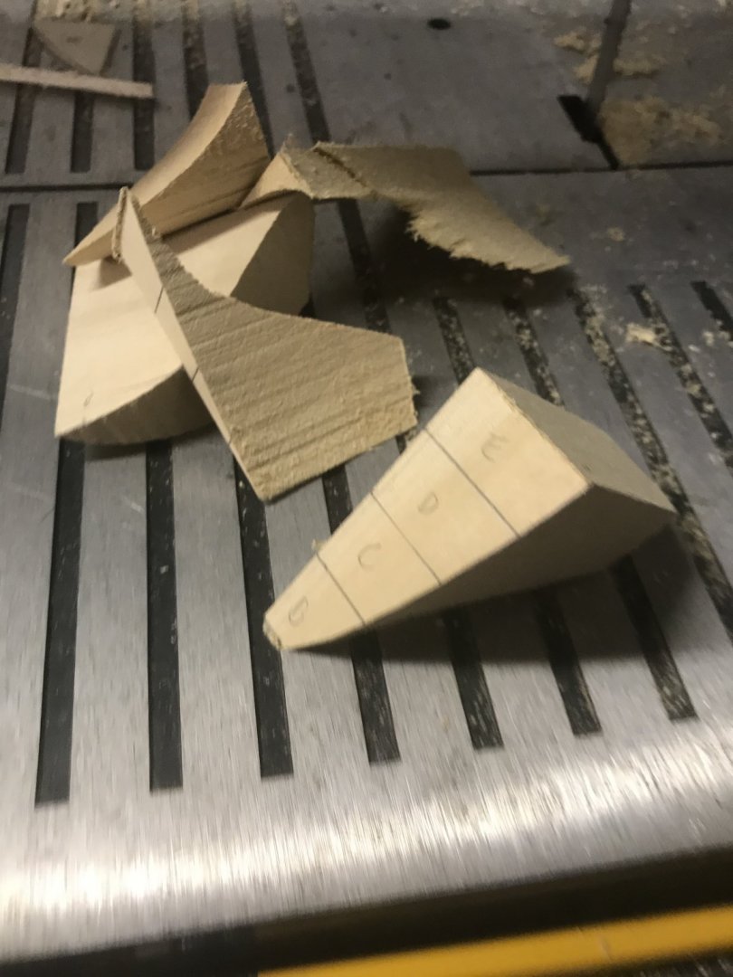
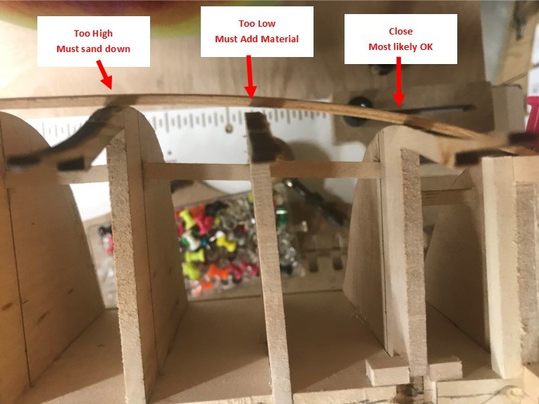
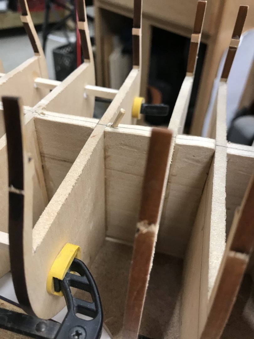
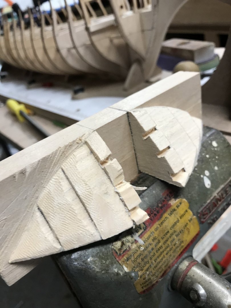
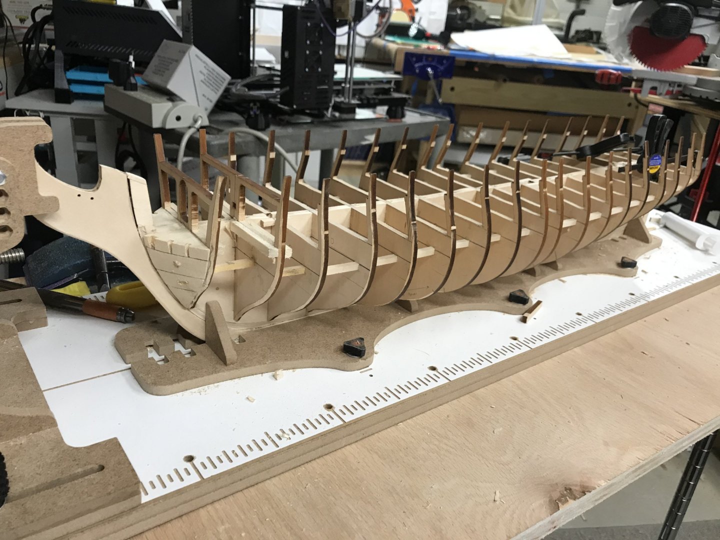
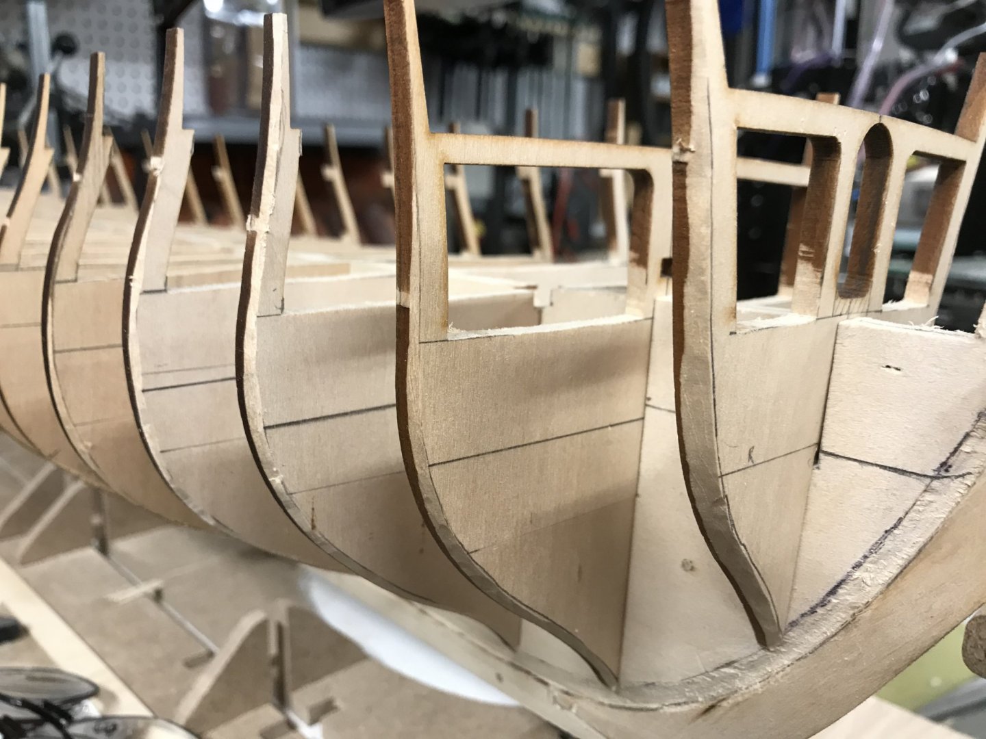
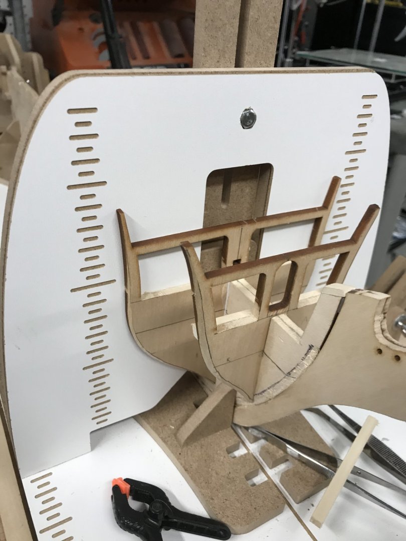
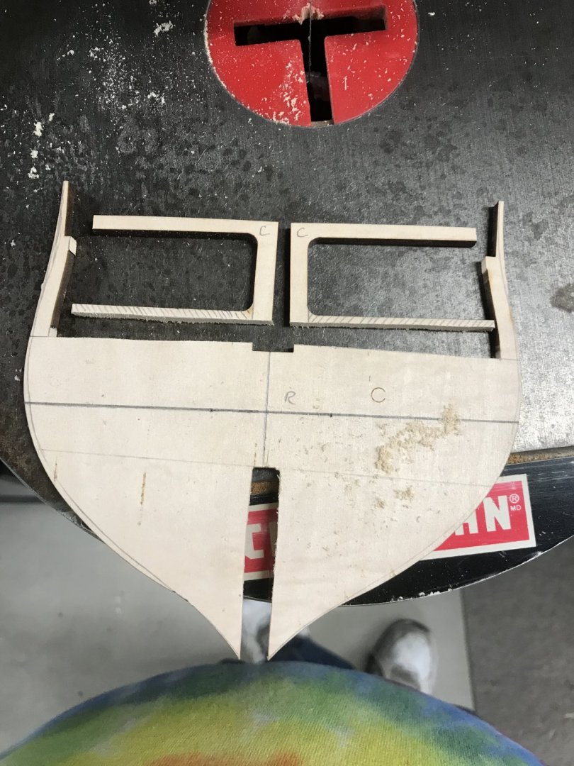
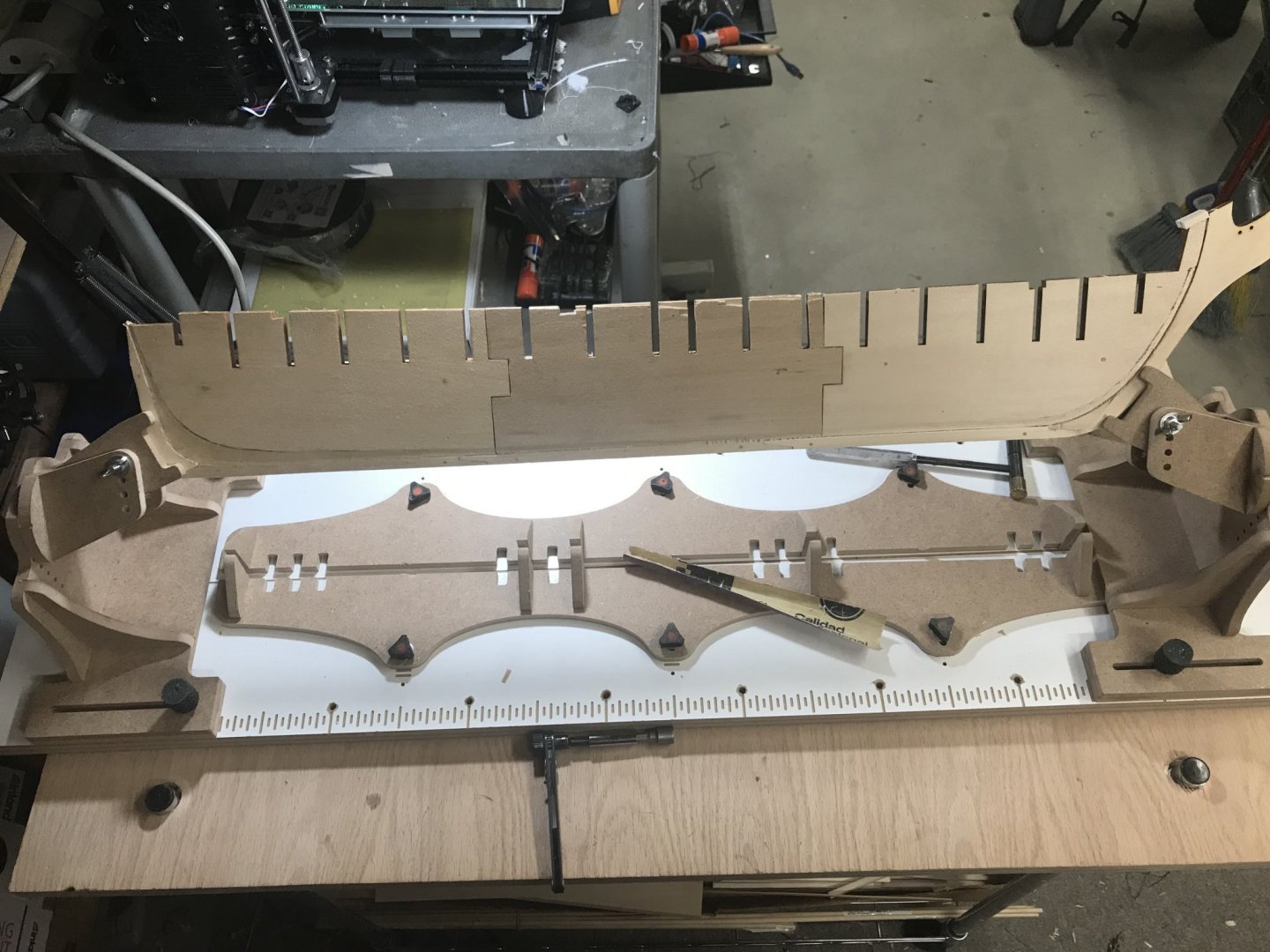
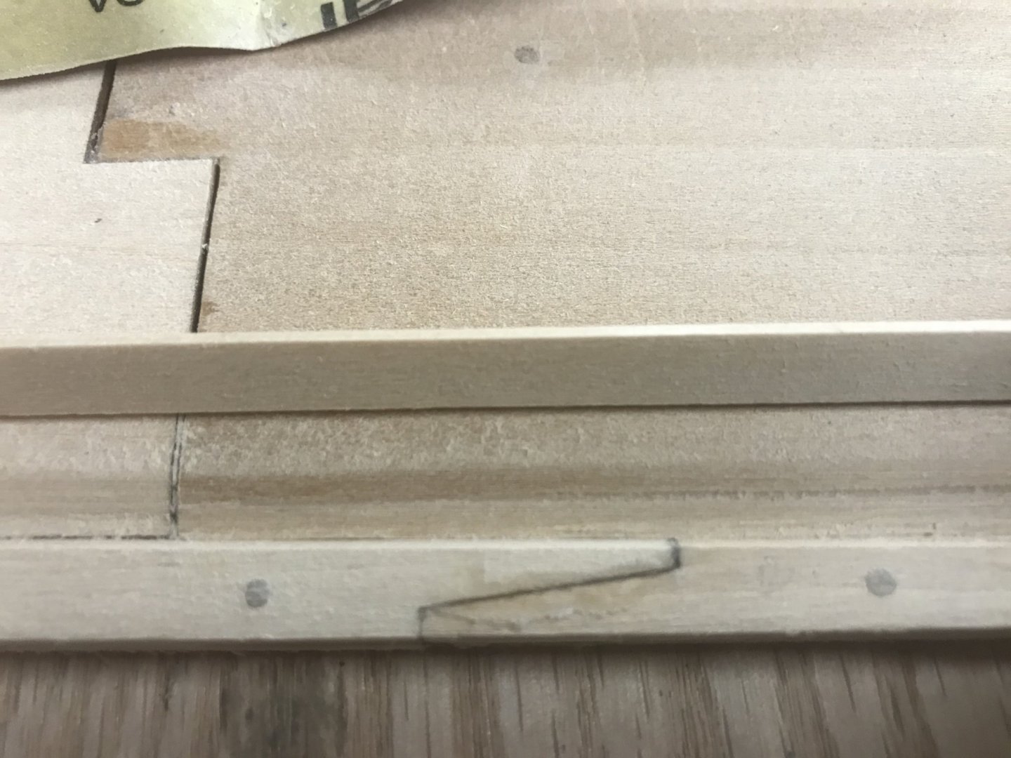
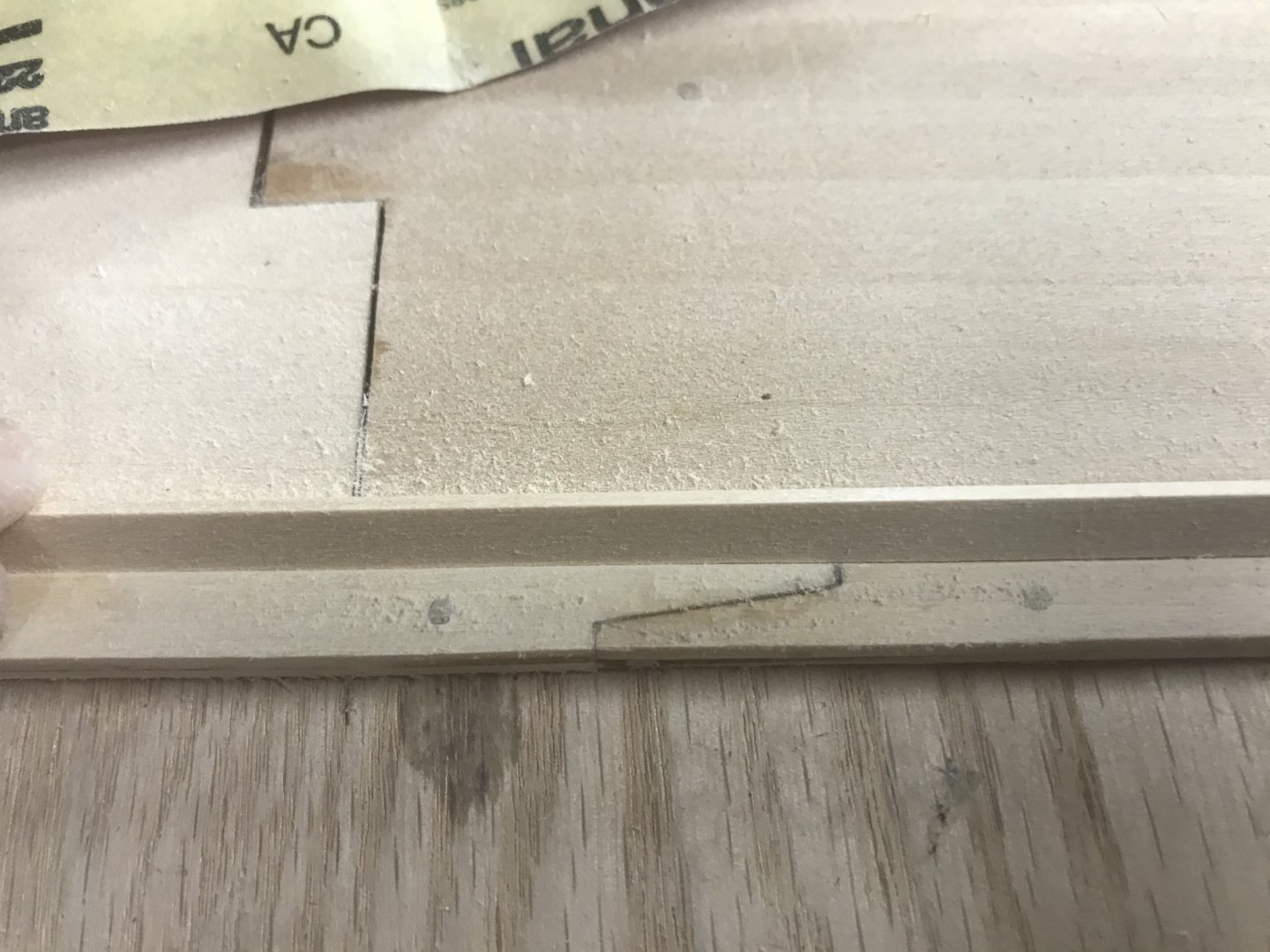
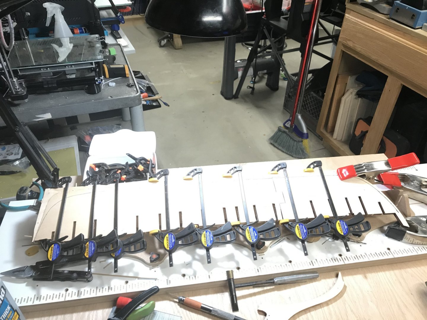
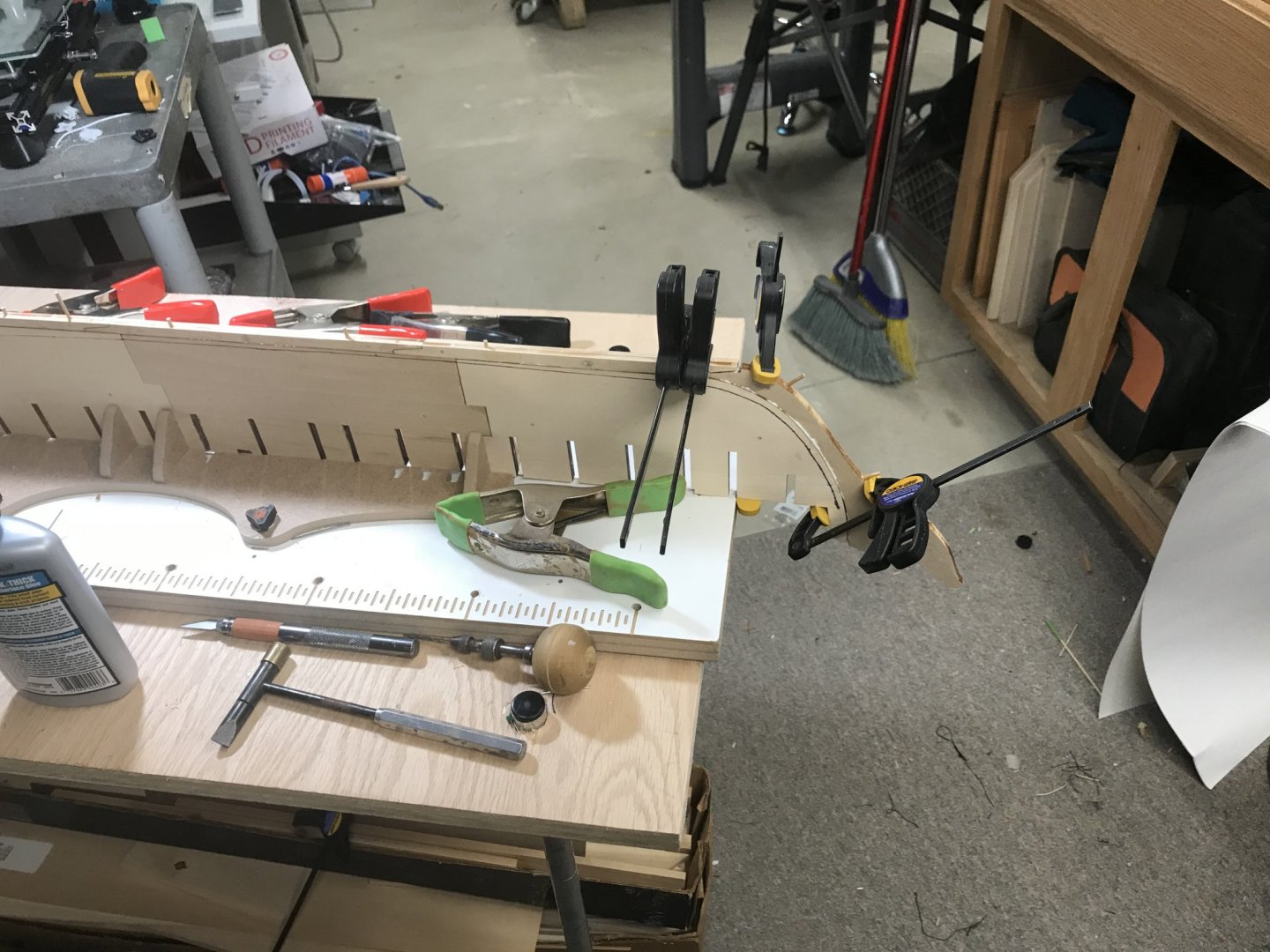
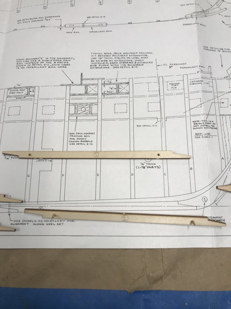
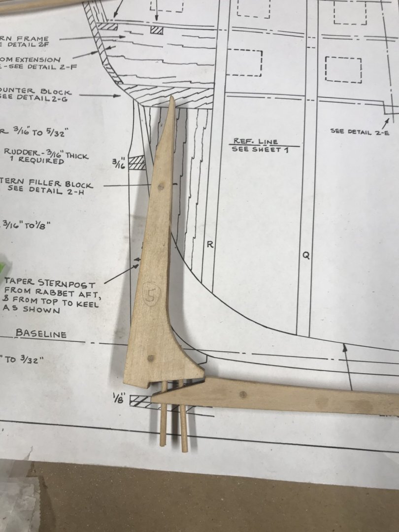
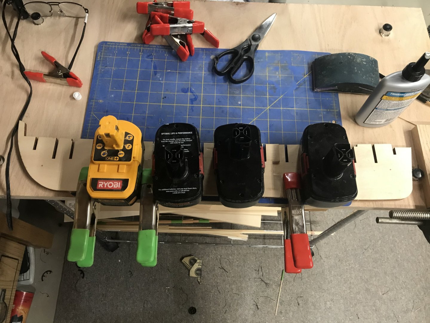
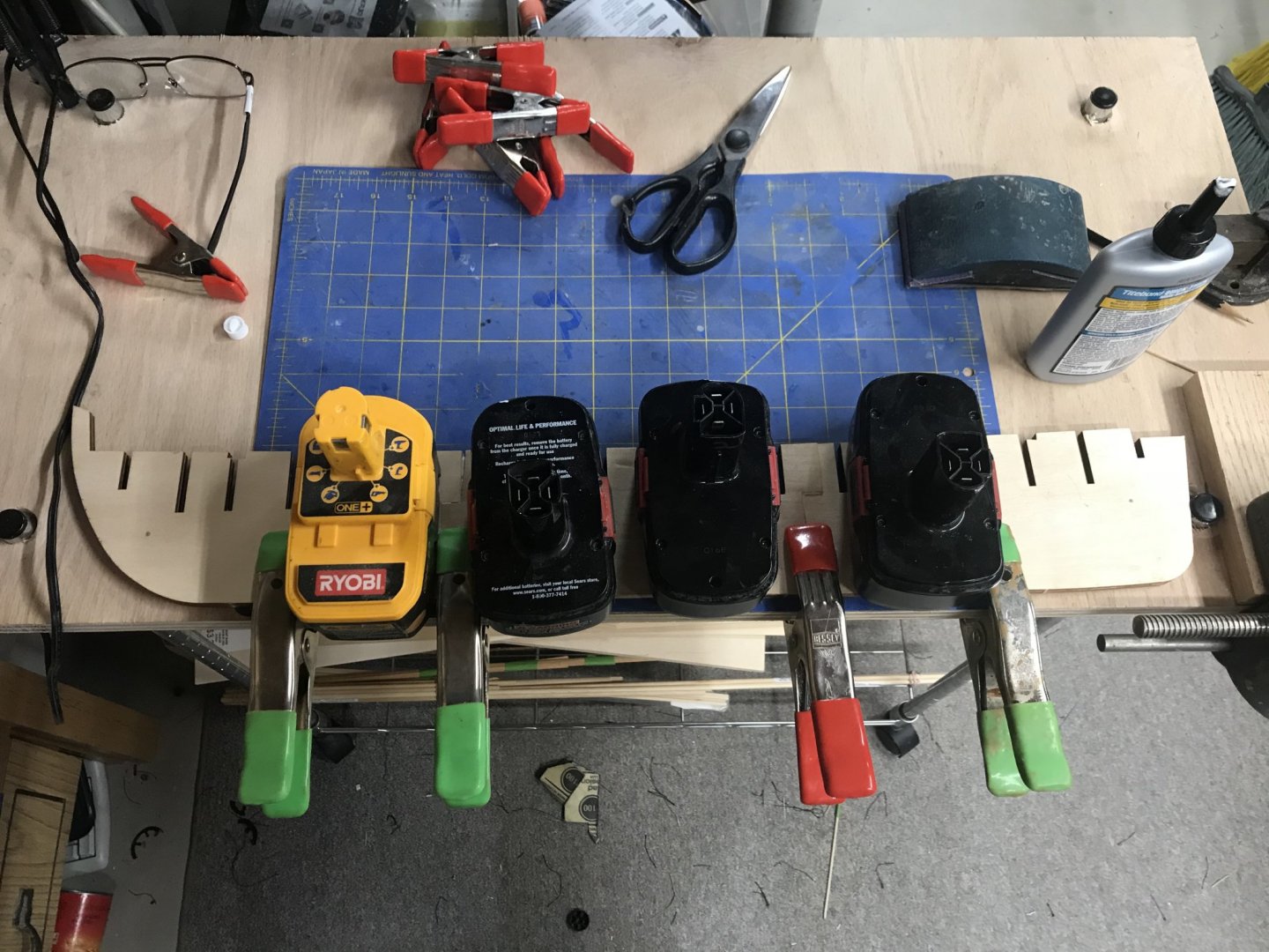
April 3, 2020 With the bow blocks in place, my attention is now focused on the stern blocks. I know I wasn’t super clear in my description for the bow blocks, so I will attempt to better describe my process with the stern. So the first thing I do is look at the plans and determine the overall dimensions of the blocks. Fortunately, this model has that information in the plans. I took the measurements and transferred them to the full wood block. Whenever I do this I try to make sure I have at least two square edges to work from. Using my adjustable square, I mark the first measurement on the block and draw a line around the whole block. Then I do the second measurement drawing the line around the block , and finally the same with the third measurement. I write the measurments on the block so that I don’t screw up and measure wrong. You know the old saying….”measure twice …….cut once….. I take the block to the band saw and cut along the lines taking care to cut it so that I have the least amount of waste. You never know when you might need to use the waste cut for something else. Now I have two blocks that are symmetrical. The next step is to make the patterns for the top, side and back of the piece. The top and side I got from the plans, photo copied them, and glued them to a piece of cardstock. I traced these templates directly to the top and side of the block. The back was traced directly by placing the block against the last frame and tracing the outline of the frame directly to the wood. Now comes the fun part ….the cutting. In my previous post I mentioned woodturner’s double sided tape. Here are a couple of links of where you can get some: https://www.rockler.com/double-sided-turners-tape?sid=V91040&promo=shopping&utm_source=google&utm_medium=cpc&utm_term=&utm_content=pla_with_promotion&utm_campaign=PL&tid=pla&gclid=CjwKCAjwvZv0BRA8EiwAD9T2Va4XGE0tJyDrXOR7un3G7xFxMTO6NhauWahSXA4VuGs5duL50iUB2xoCASIQAvD_BwE https://www.woodcraft.com/products/double-sided-tape-1-x-36-yards?gclid=CjwKCAjwvZv0BRA8EiwAD9T2VarQS44TixJiH9JThutaizRqnbsVcRepK7CoTowiLJTyWHrR9xzkBxoCacIQAvD_BwE I use this tape to reassemble the cut block so that when I am cutting one of the sides I have a flat surface to run against the band saw table. So I cut one side of the profile, then tape the cut pieces back together. Then I cut the next profile and reassemble, finally the last side of the profile. When finished, disassemble and remove the tape and viola’ the part is cut close to the what it needs to be. I say close because you will sill need to shape and sand in order to soften the curves so that they match the hull lines. I try to do as much of the shaping off the model. I use the double sided tape and affix the parts to a piece of scrap wood and then use my rasps, files and sand paper to as correct of a shape as I can. Once I am satisfied with the shape, I glue and dowel them to the model. Fine tuning and sanding still need to be done. I will do that as part of the fairing process. This brings me to fairing your model. I went to my scrap box and found a couple of planks that run the full length of the model. I had previously, according to the instructions beveled the first few frames in the bow and stern. Using the plank I spot checked the hull at different intervals down from the plank sheer. I am generally please with how the planks lays across the frames. However there are a few high spots which also created low spots. I will be working on fairing the frames and will show the results in my next post.


-
Unegawahya reacted to a post in a topic:
USS Constitution by Henriy - Model Shipways Kit 2040 - Scale 1/76
-
Unegawahya reacted to a post in a topic:
USS Constitution by Henriy - Model Shipways Kit 2040 - Scale 1/76
-
Unegawahya reacted to a post in a topic:
USS Constitution by Henriy - Model Shipways Kit 2040 - Scale 1/76
-
Unegawahya reacted to a post in a topic:
USS Constitution by Henriy - Model Shipways Kit 2040 - Scale 1/76
-
GrandpaPhil reacted to a post in a topic:
USS Constitution by Henriy - Model Shipways Kit 2040 - Scale 1/76
-
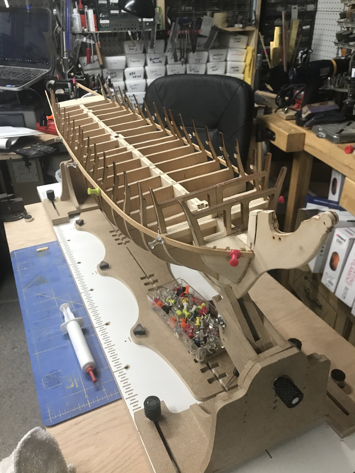
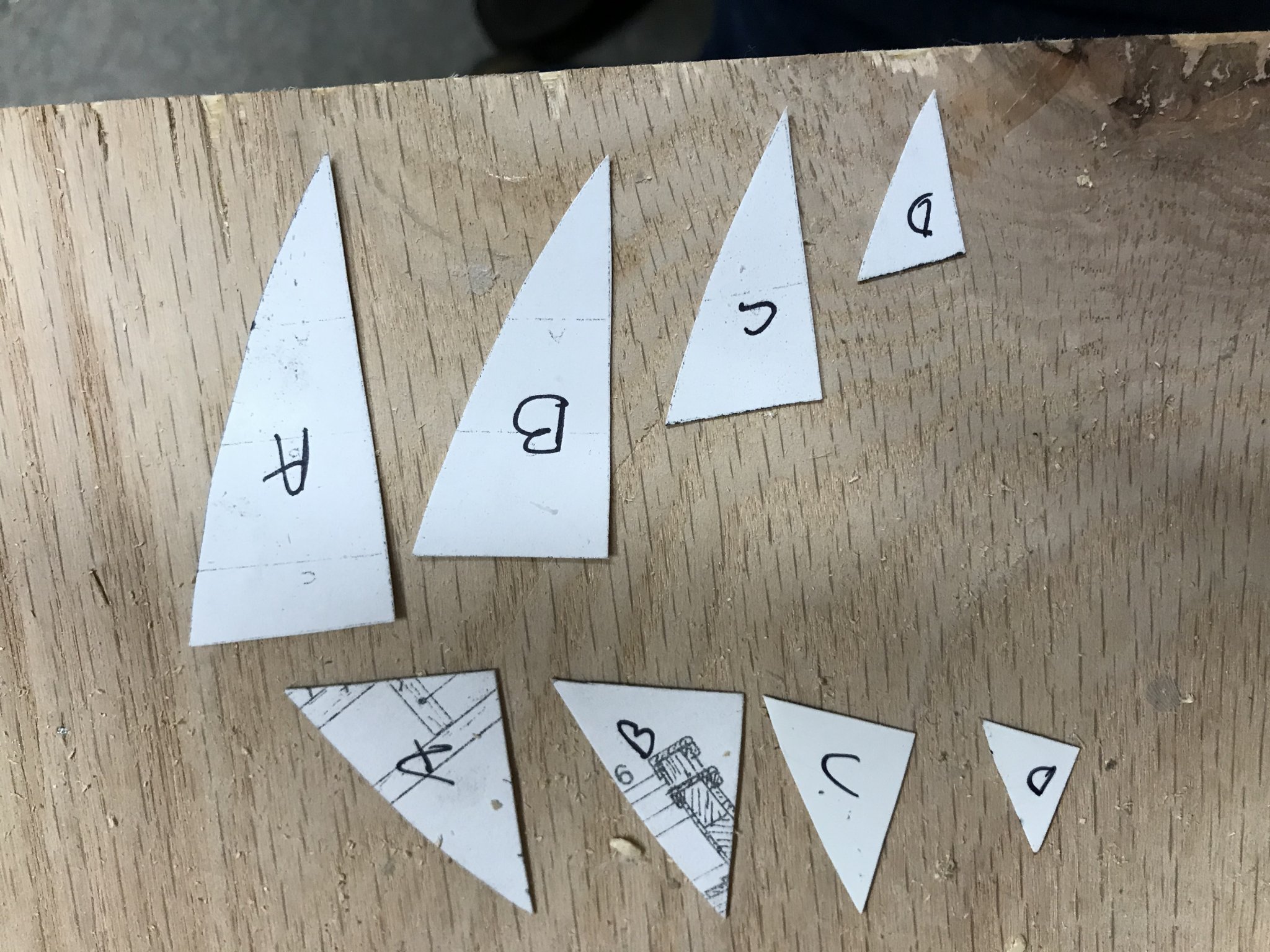
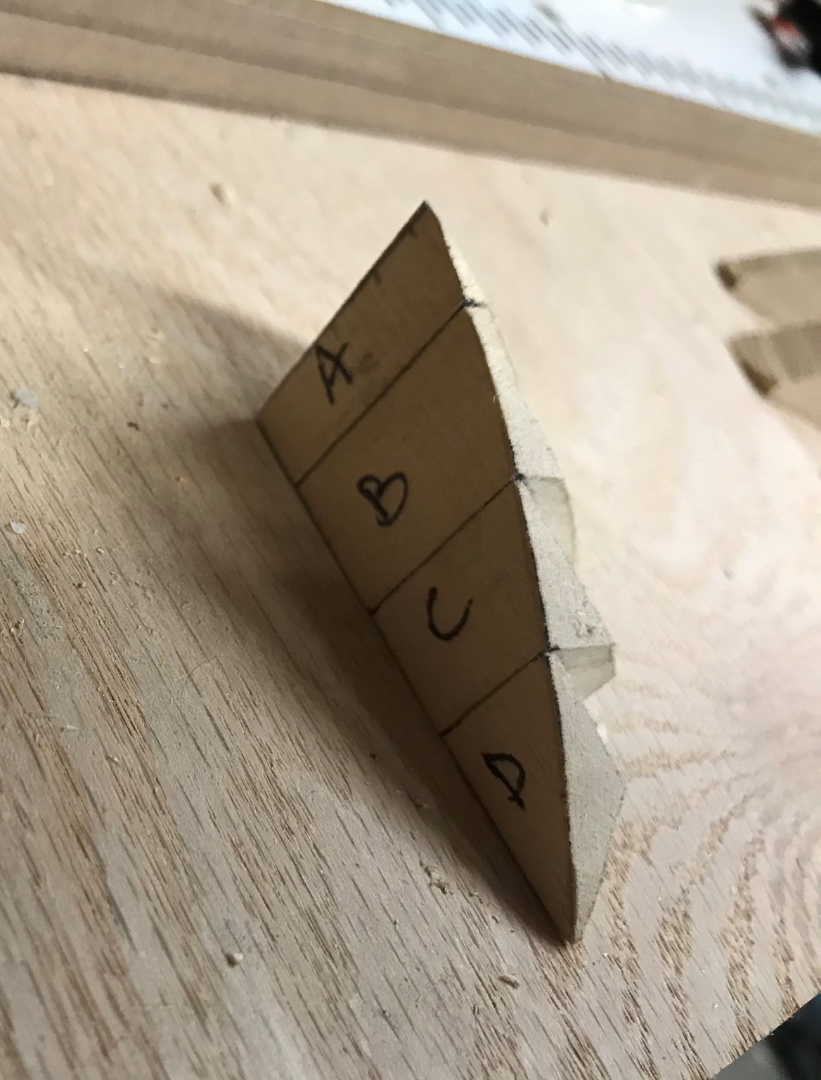
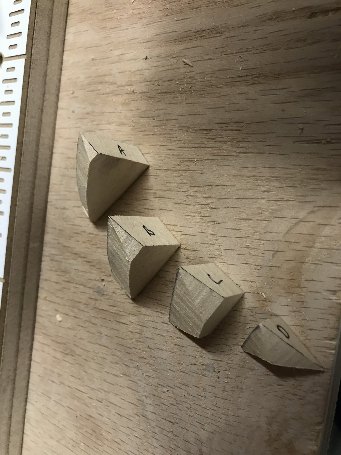
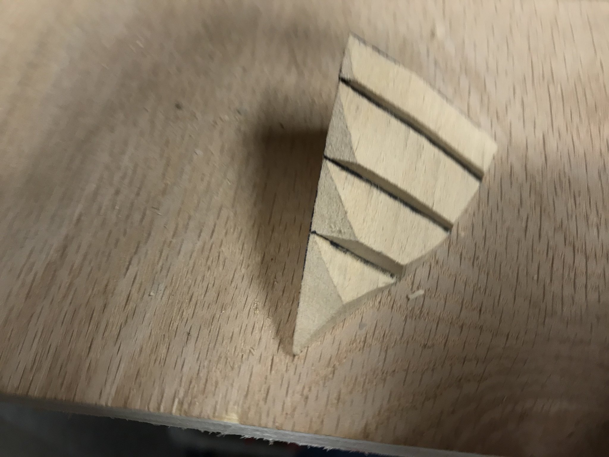
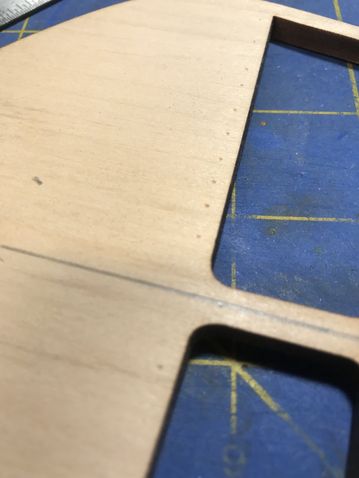
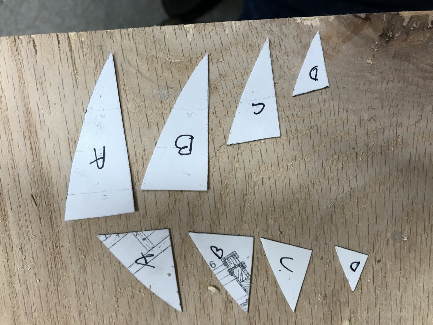
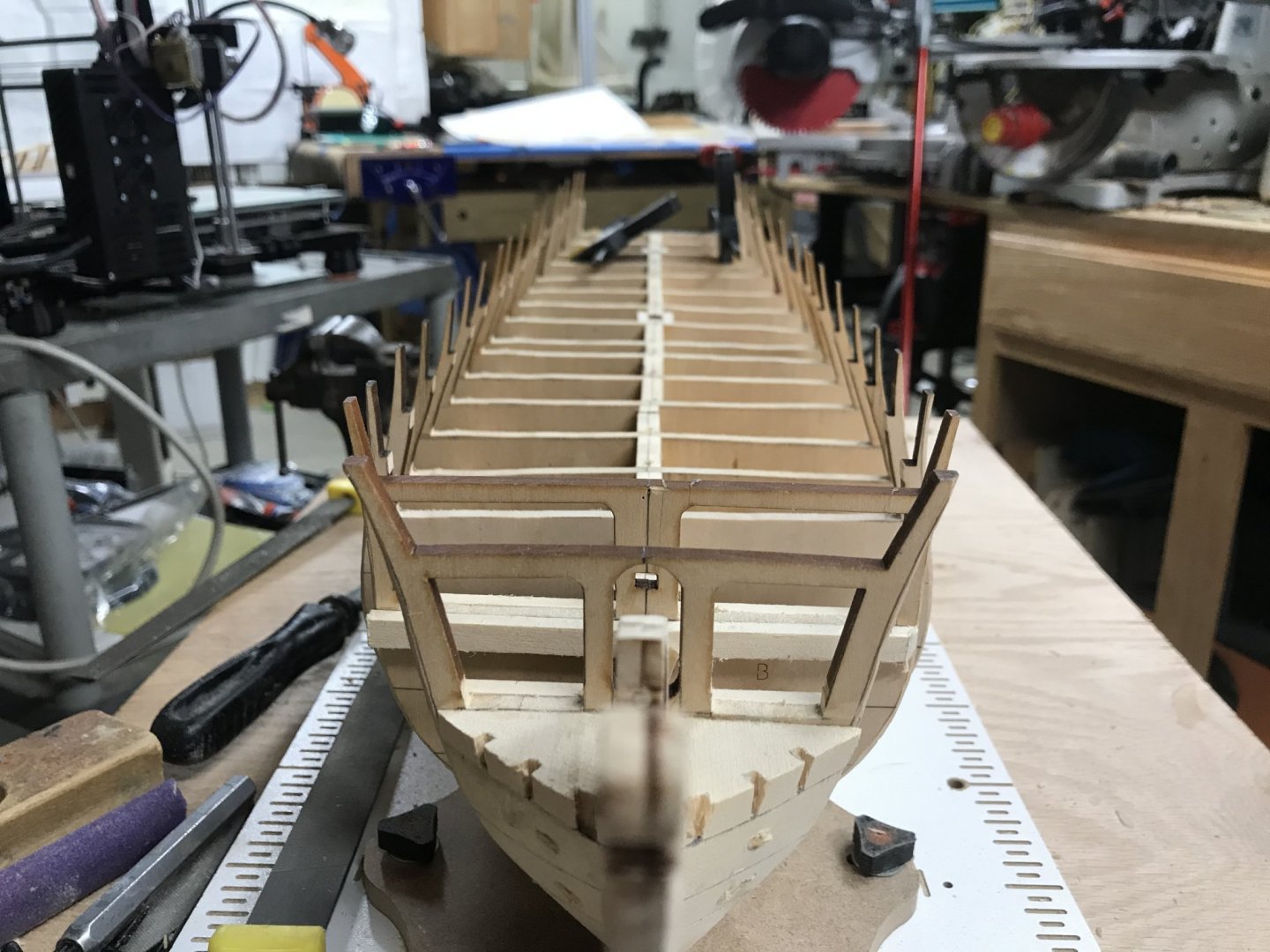
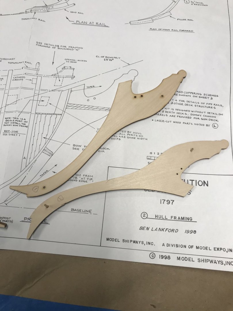
March 30, 2020 Today, after my work at home responsibilities were completed, I went into my workshop and worked on the model for a bit. My goal for today was to dowel all the frames into place and install the bow blocks. I drilled a pilot hole at an angle from behind the frame. I made sure that the hole drill passed through the frame and into the false keel. You might say to yourself, “why bother?” For me it’s tradition. That is the way my grandfather taught my uncle. And my uncle taught me. Hopefully my boys will want to learn and I will teach them. The technical reason is that over time the glue will dry out and the frames could pull apart. Having a mechanical fastener helps mitigate this and ensures that the frame wont move. Once each frame was secured, I moved onto the bow block. Most people try to carve the bow and stern blocks from one piece of wood. I used to be one of those people. If the plans provide the lines of the block this method is easy. First of all I make multiple copies of the section in the plans that show the filler blocks. Three or four should do it. Then I cut out the pieces on the plan copies. I use spray rubber cement and adhere the pieced to card stock. In this model I cut out the first template showing the pieces’ whole profile. Then the next template is cut down a little smaller, etc. I traced the lines to my block of wood on the top to the port side . Before we cut anything I want to remind you not to throw away any of the waste cuts, you will need them. I cut the side profile with my band saw. Then I dissect the piece according to the A-D template . Now I have 4 sections that one side is shaped. I next use the top template and transfer the lines on each piece both top and bottom. The bottom of piece A is the same as the top of piece B, etc.. Cut each piece using the top profile of each. I reassemble the pieces using wood turners double sided tape. Place the reassembled piece on the hull and trace the first frame to it. Now using the turners tape I reassembled the block of wood using the waste cut pieces. Your final cut is done on the tracing of the first frame on the block. Now disassemble and glue together pieces A-D. This seems like a lot of work, but compared to trying to carve the block by hand, I think it is more accurate and you spend less time shaping because the band saw did most of the work. With both bow blocks completed. I used turners tape to attach them to the hull. Then I drilled a couple of dowel holes. Glued it all up and secured with dowels All that is left to do is some fine tuning when I start fairing the hull. Next will be the stern blocks. I will use the same method and try to document it better than I did the bow.


-
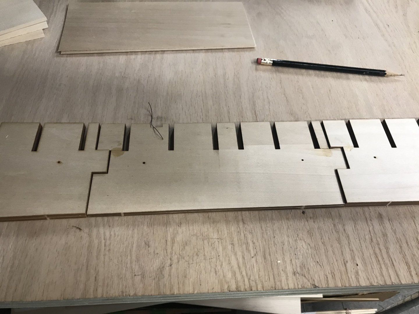
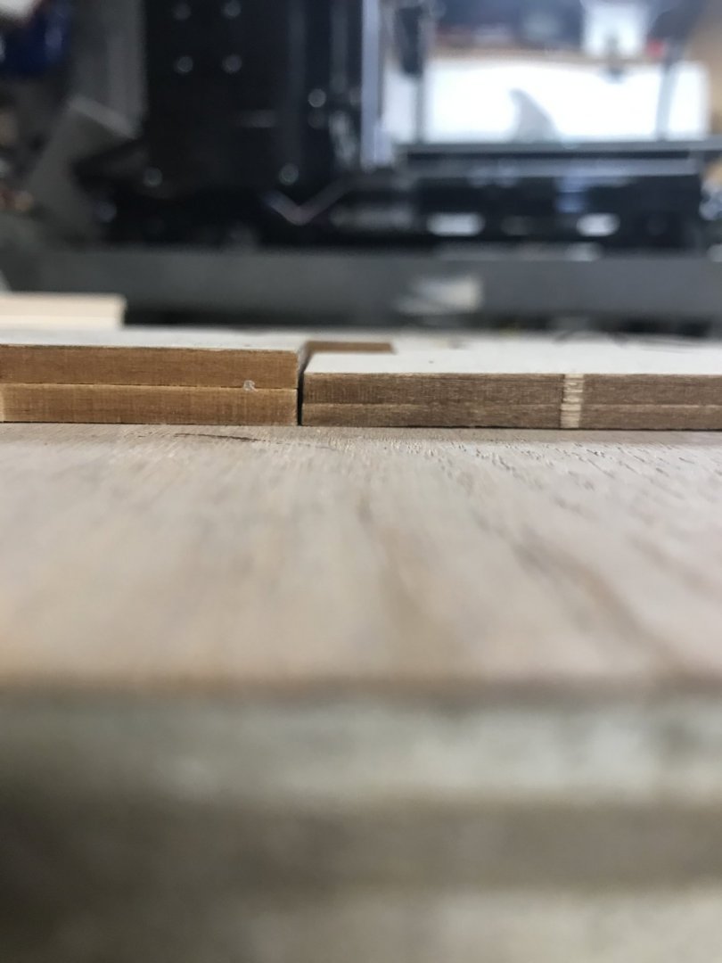
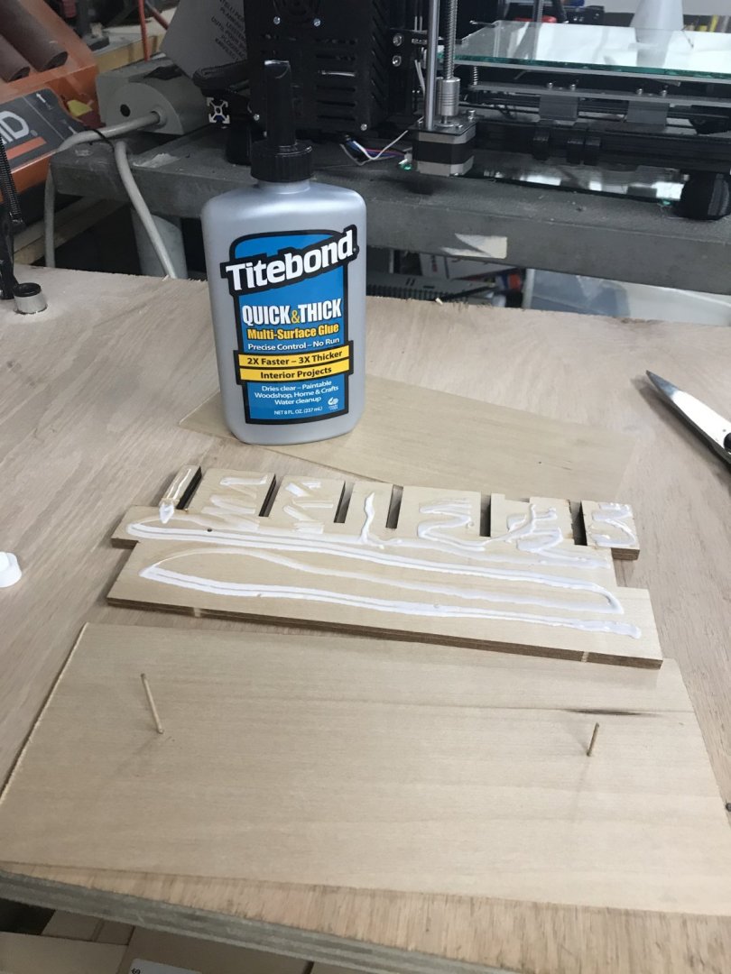
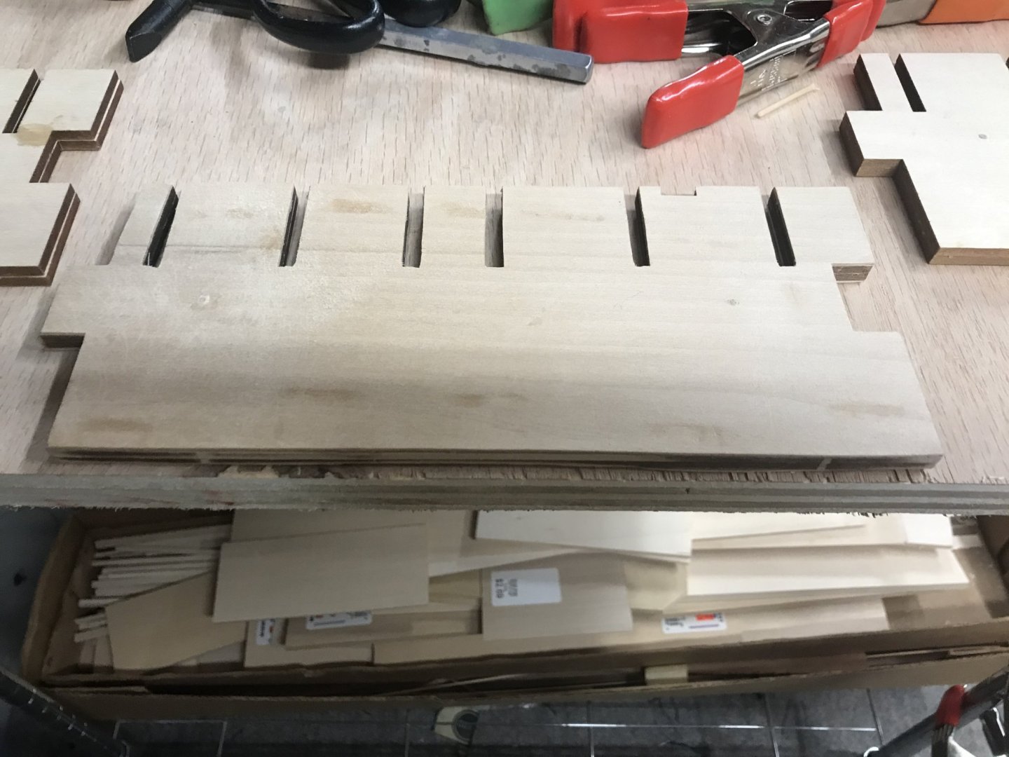
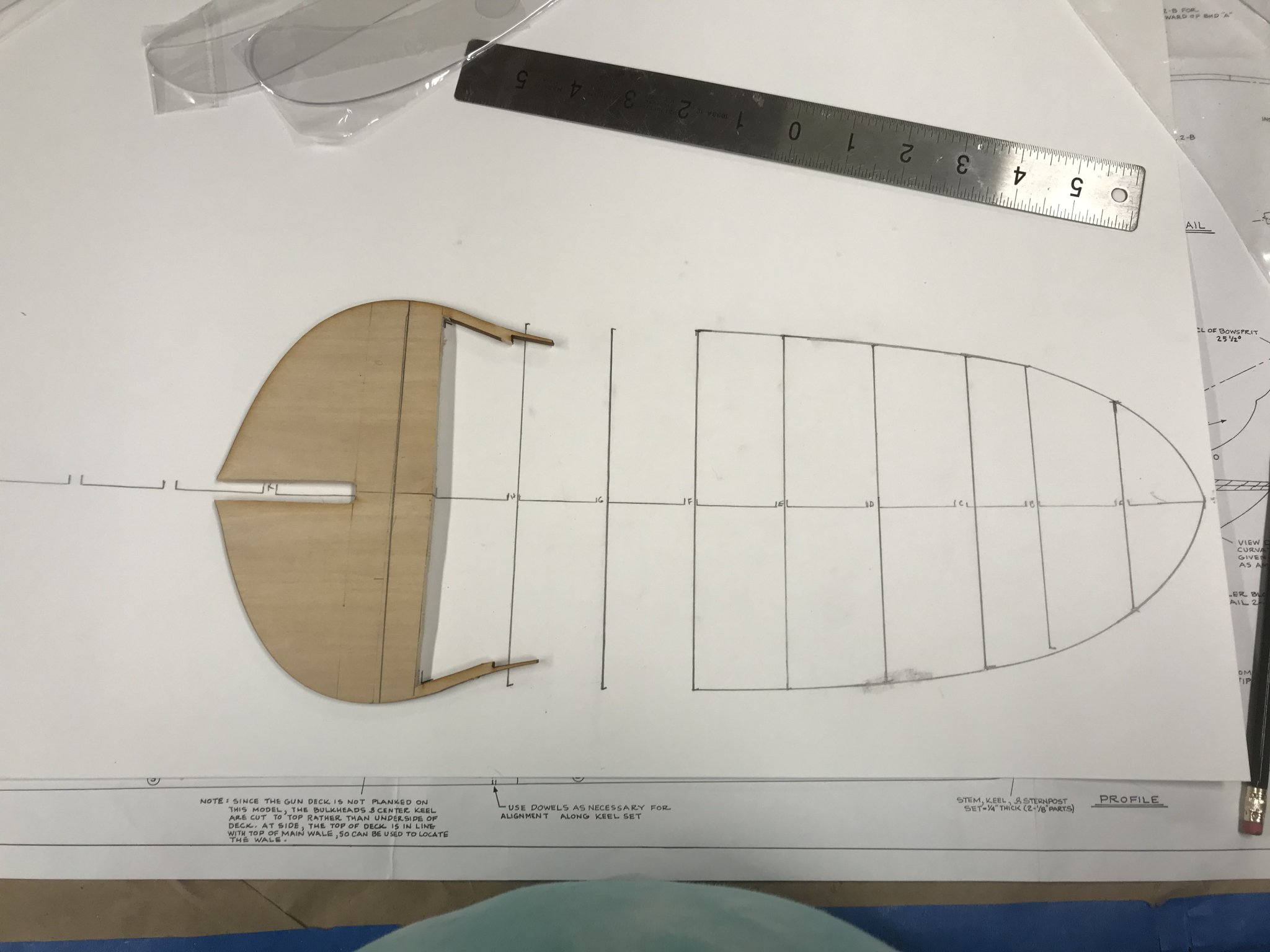
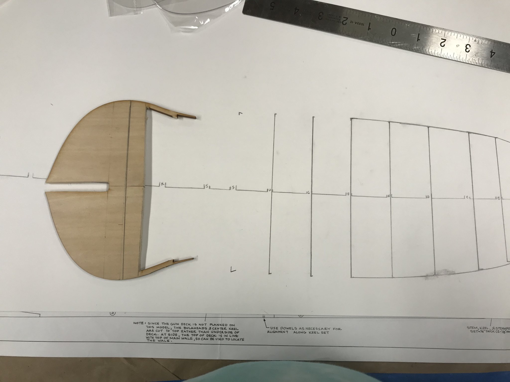
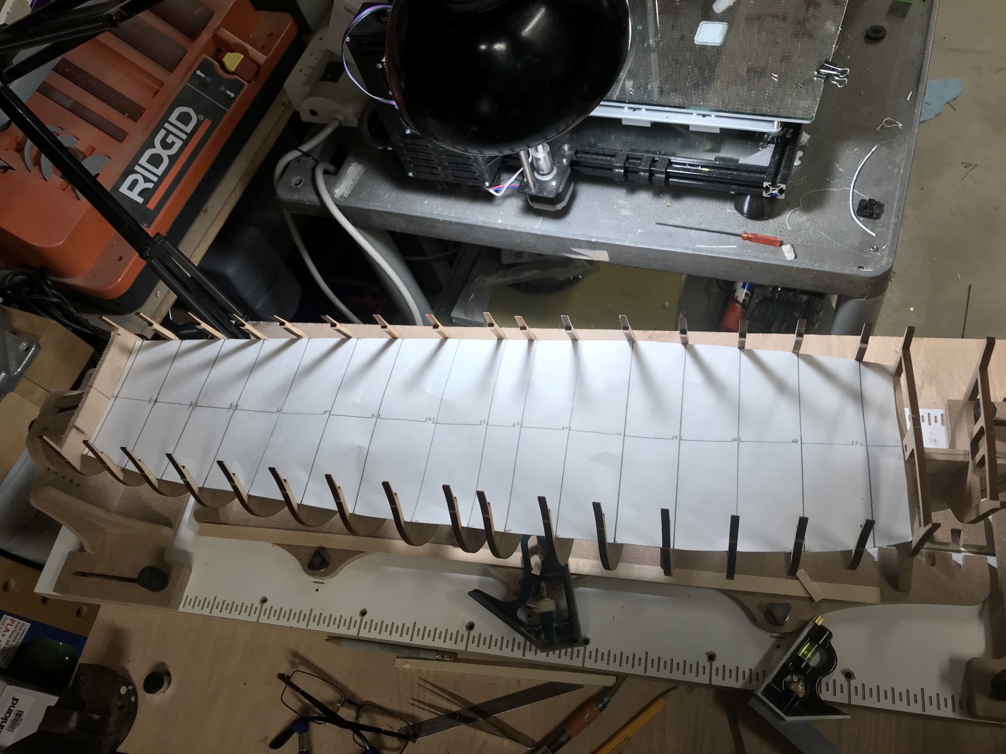
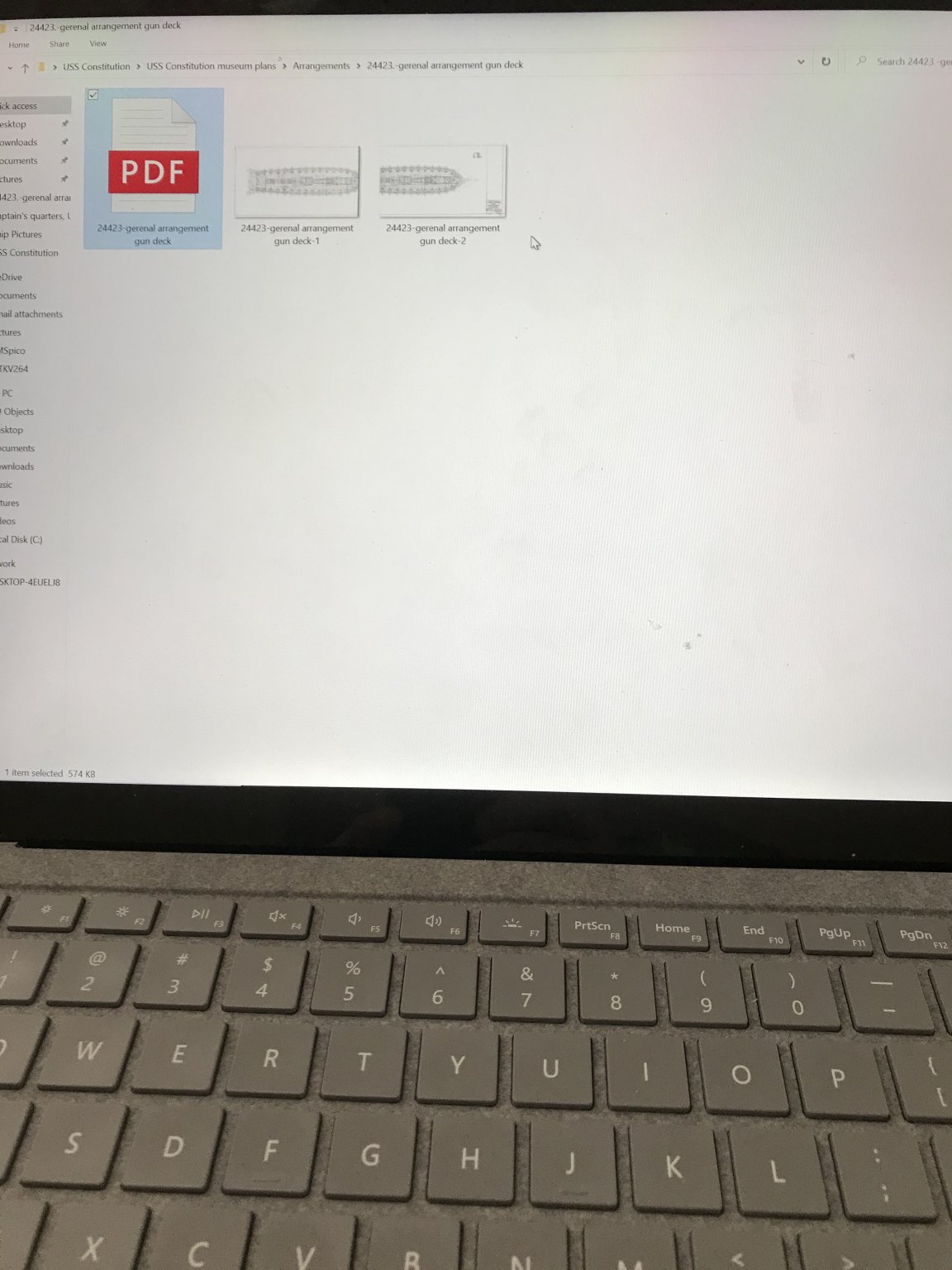
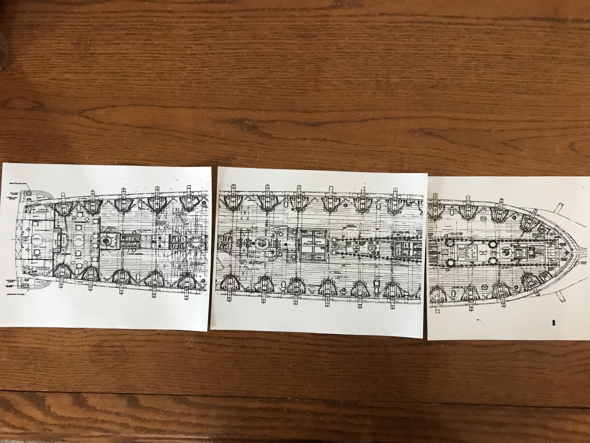
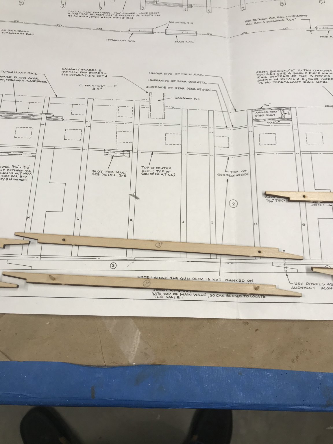
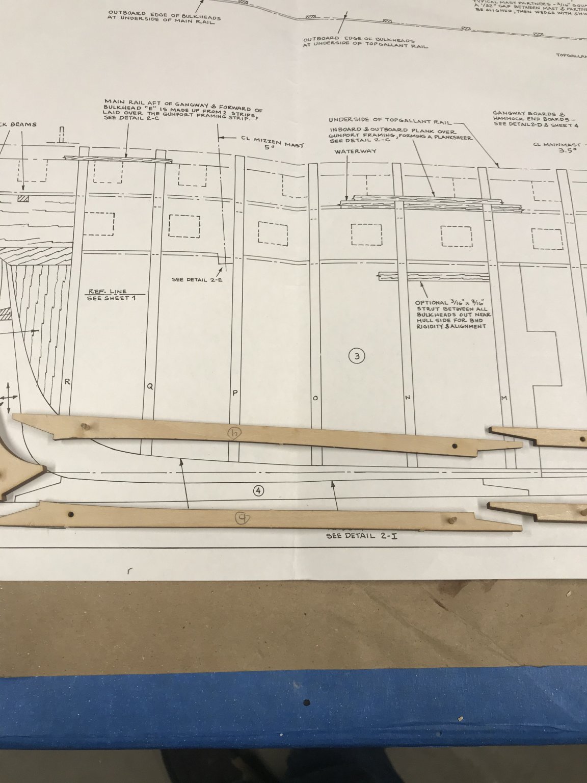
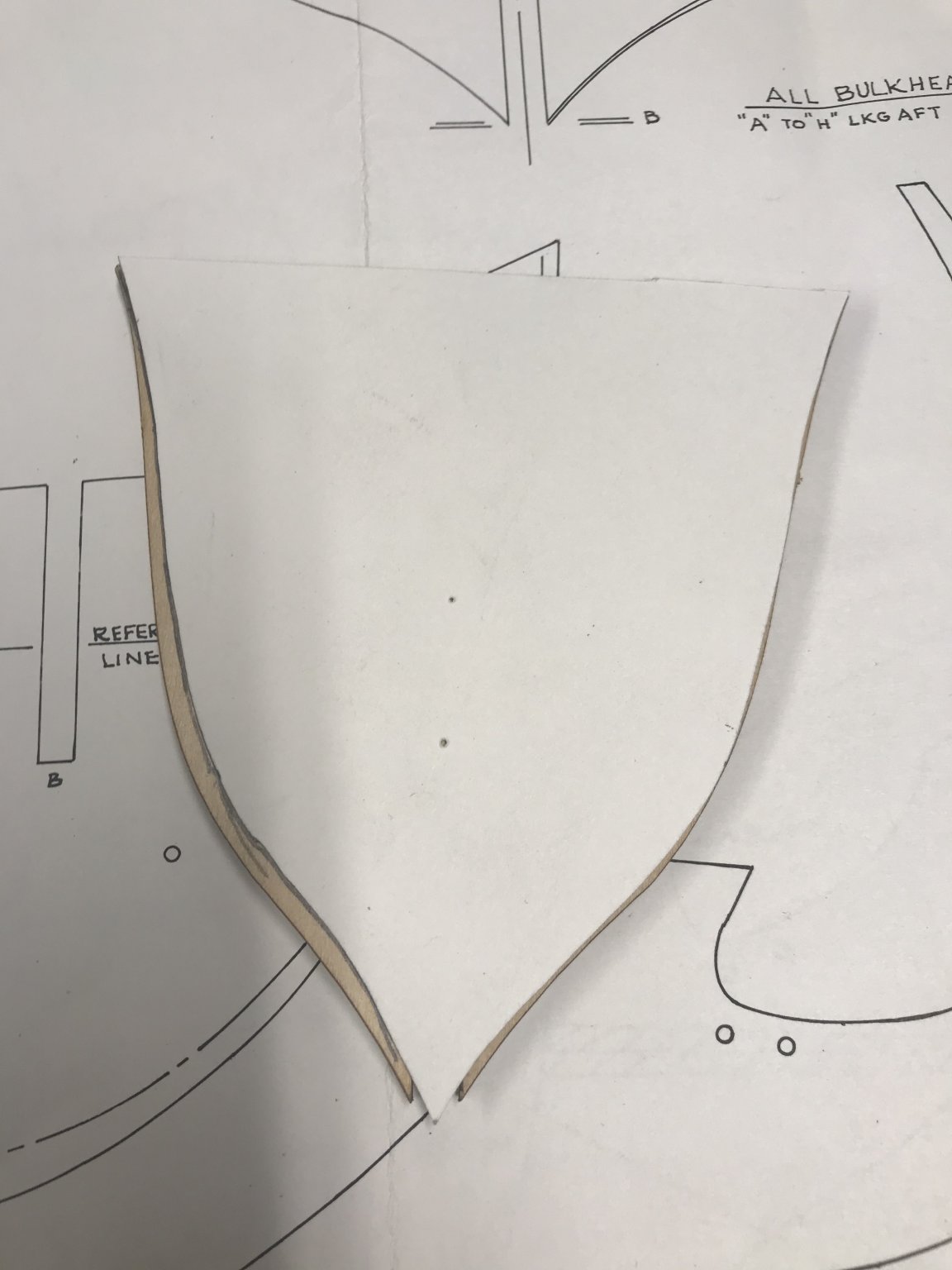
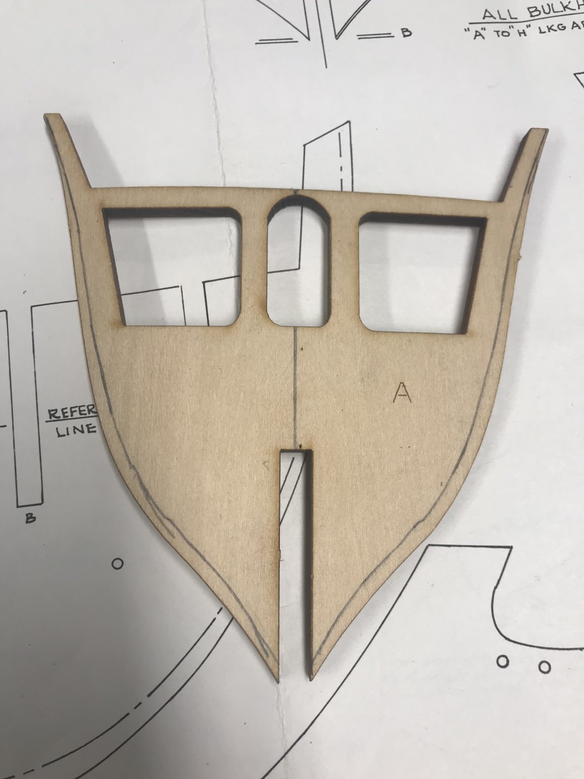
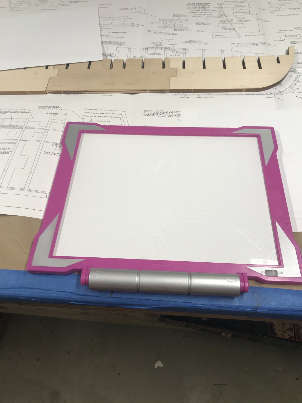
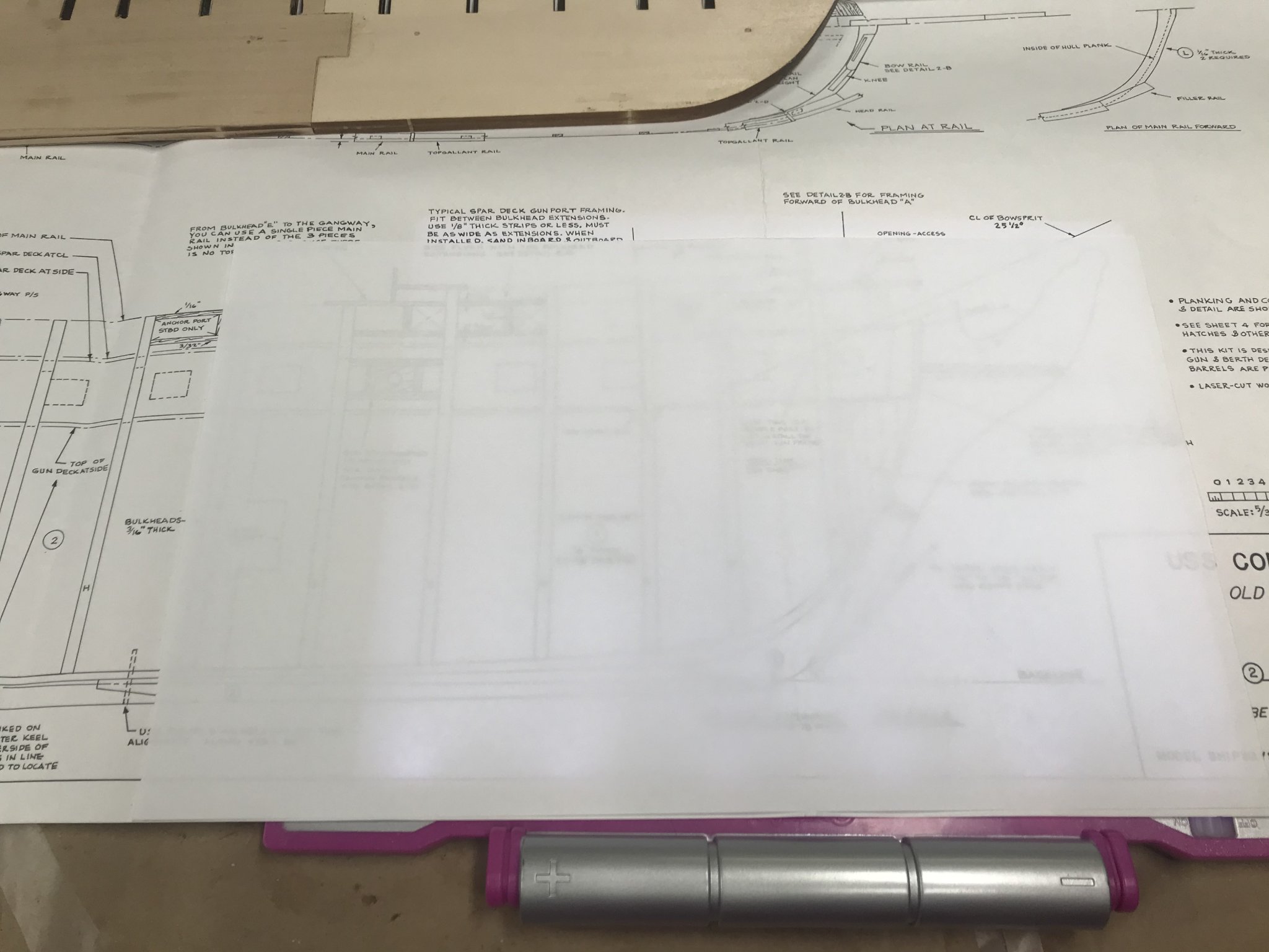
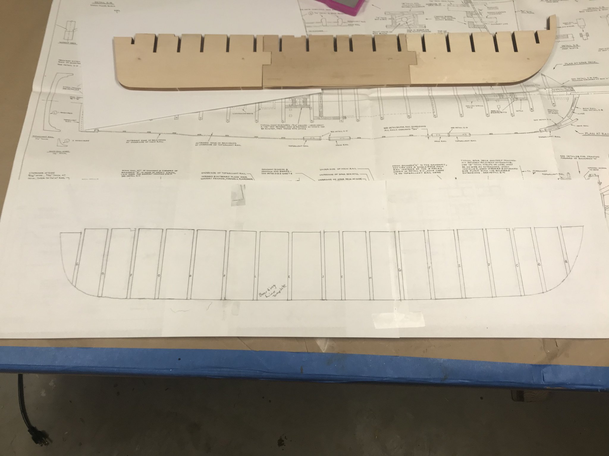
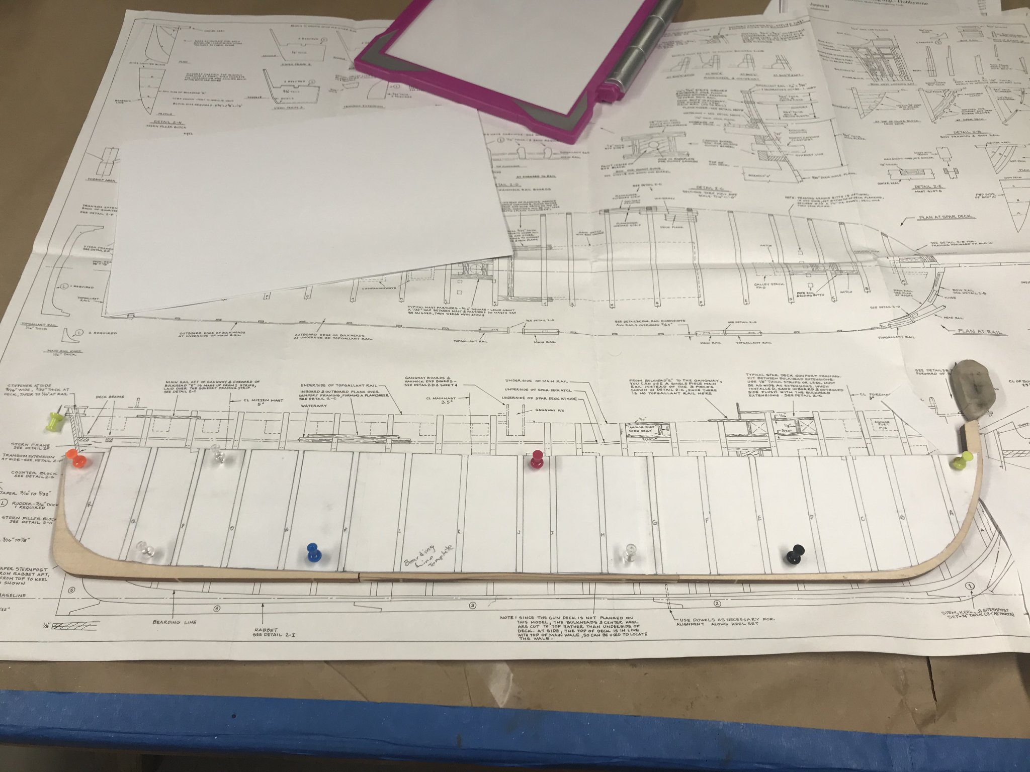
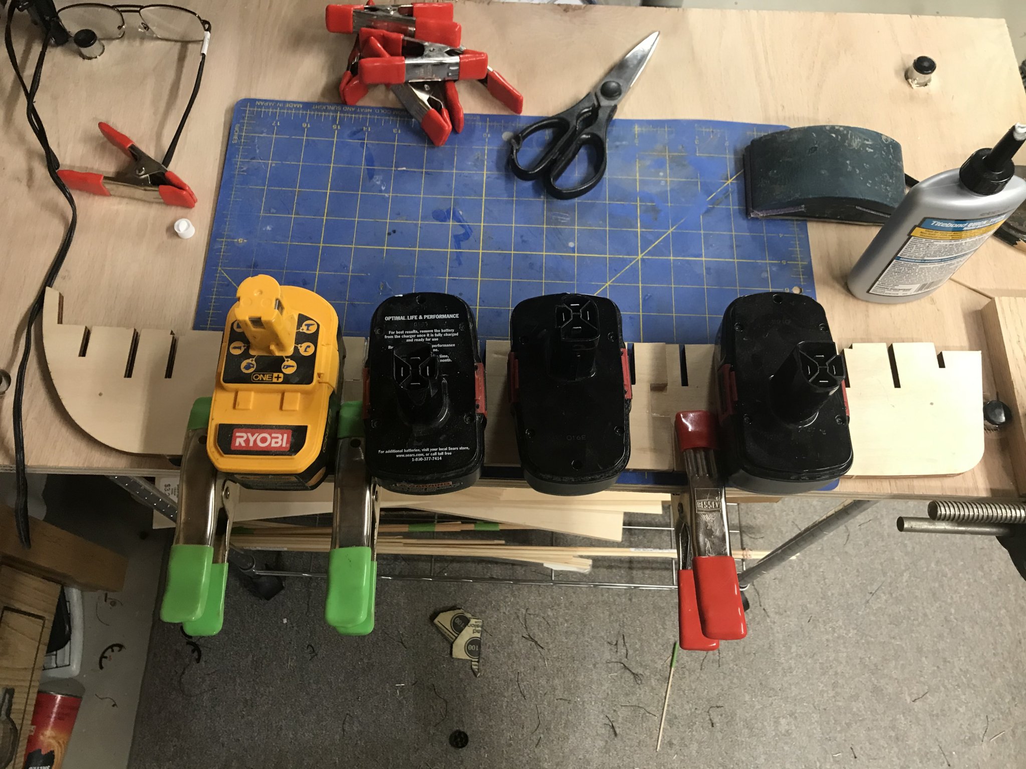
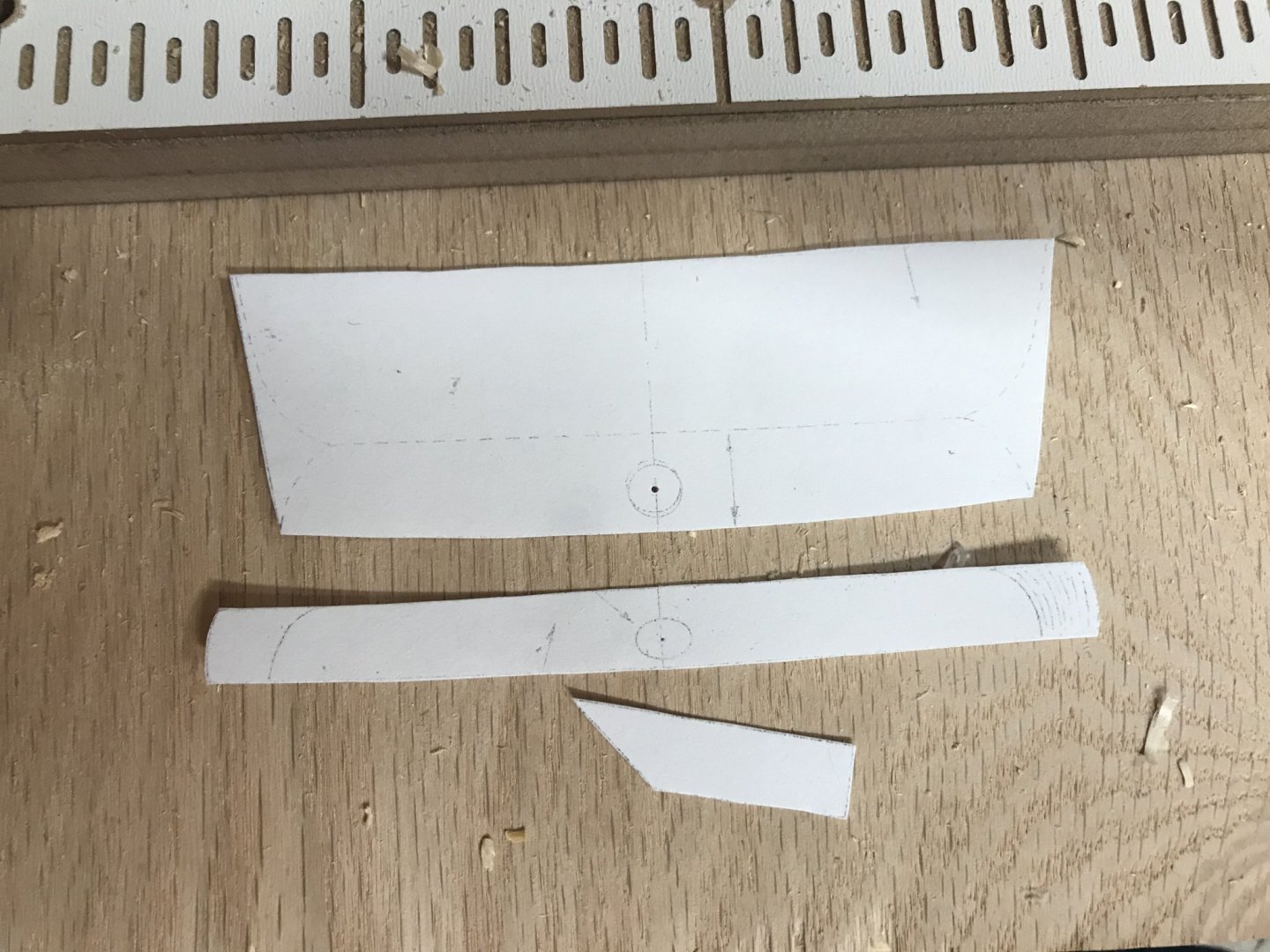
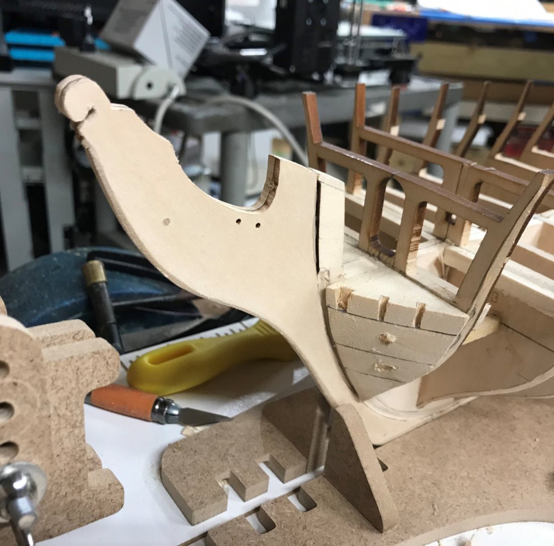
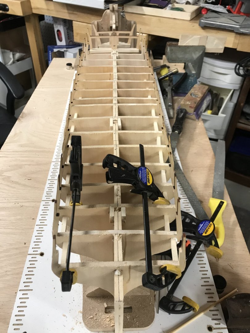
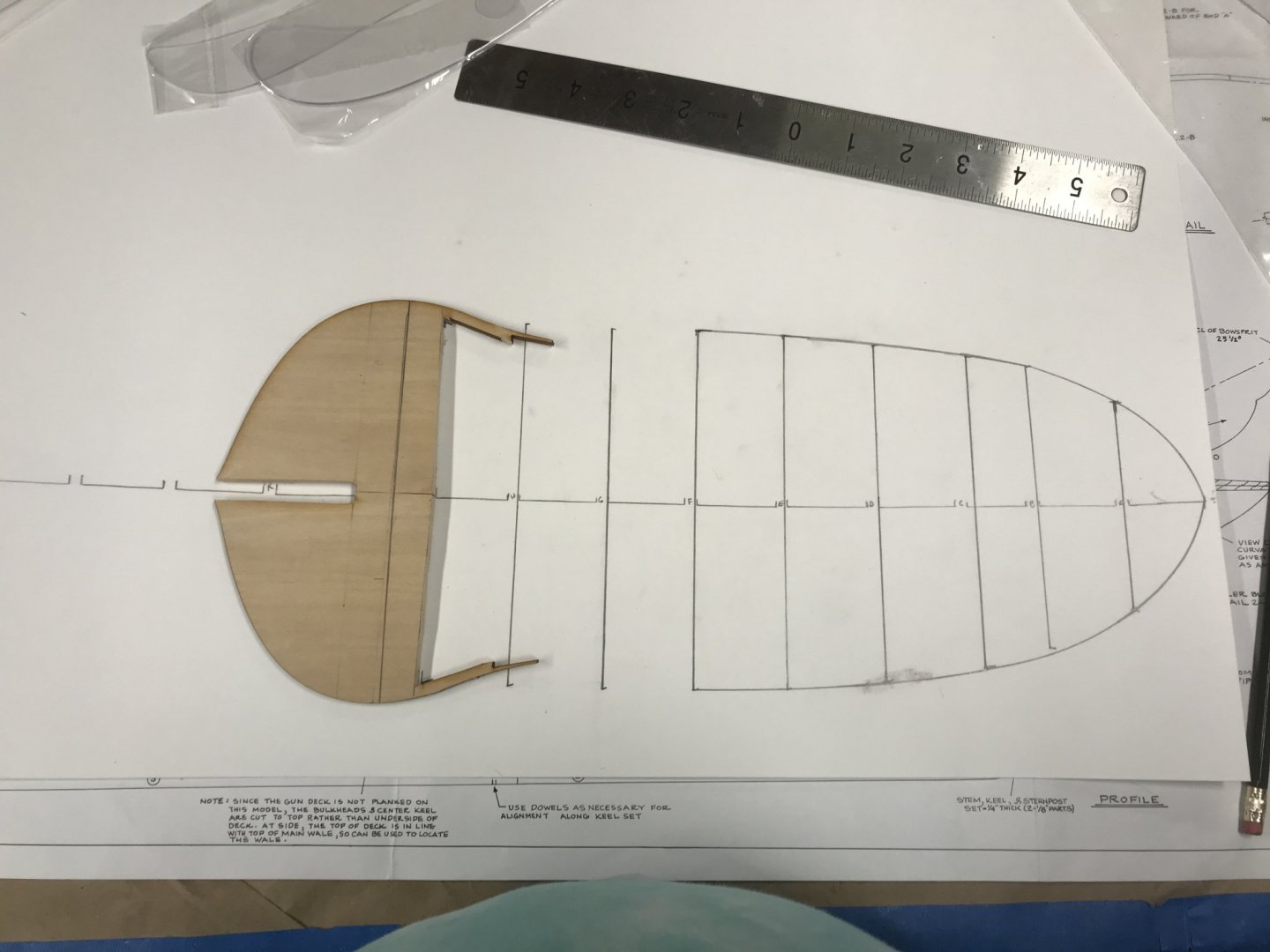
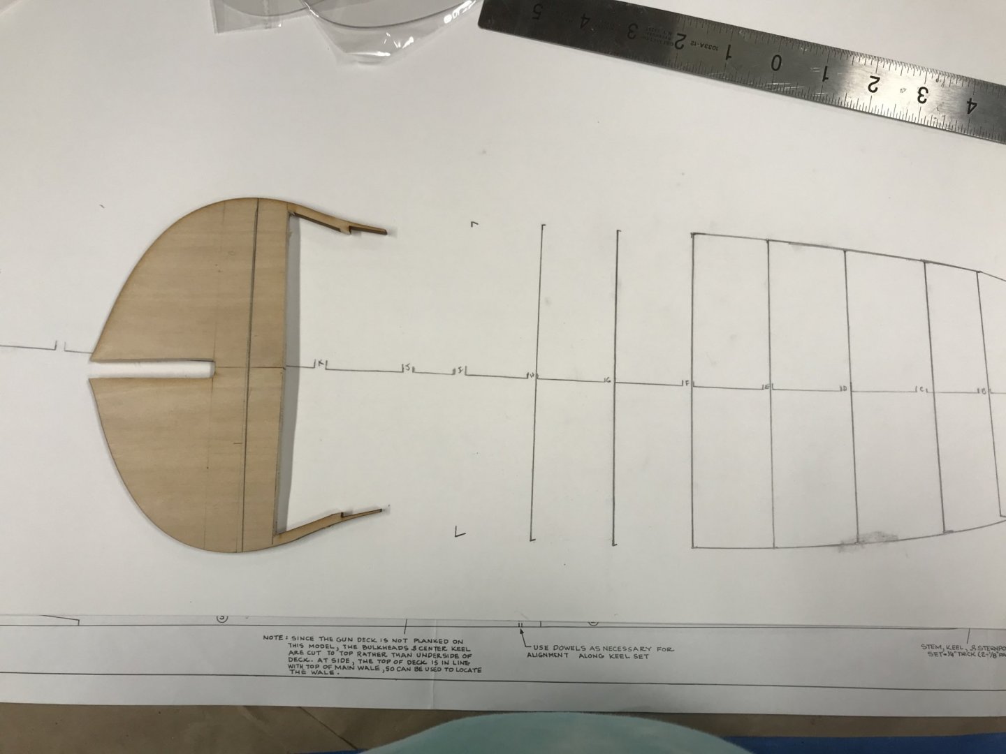
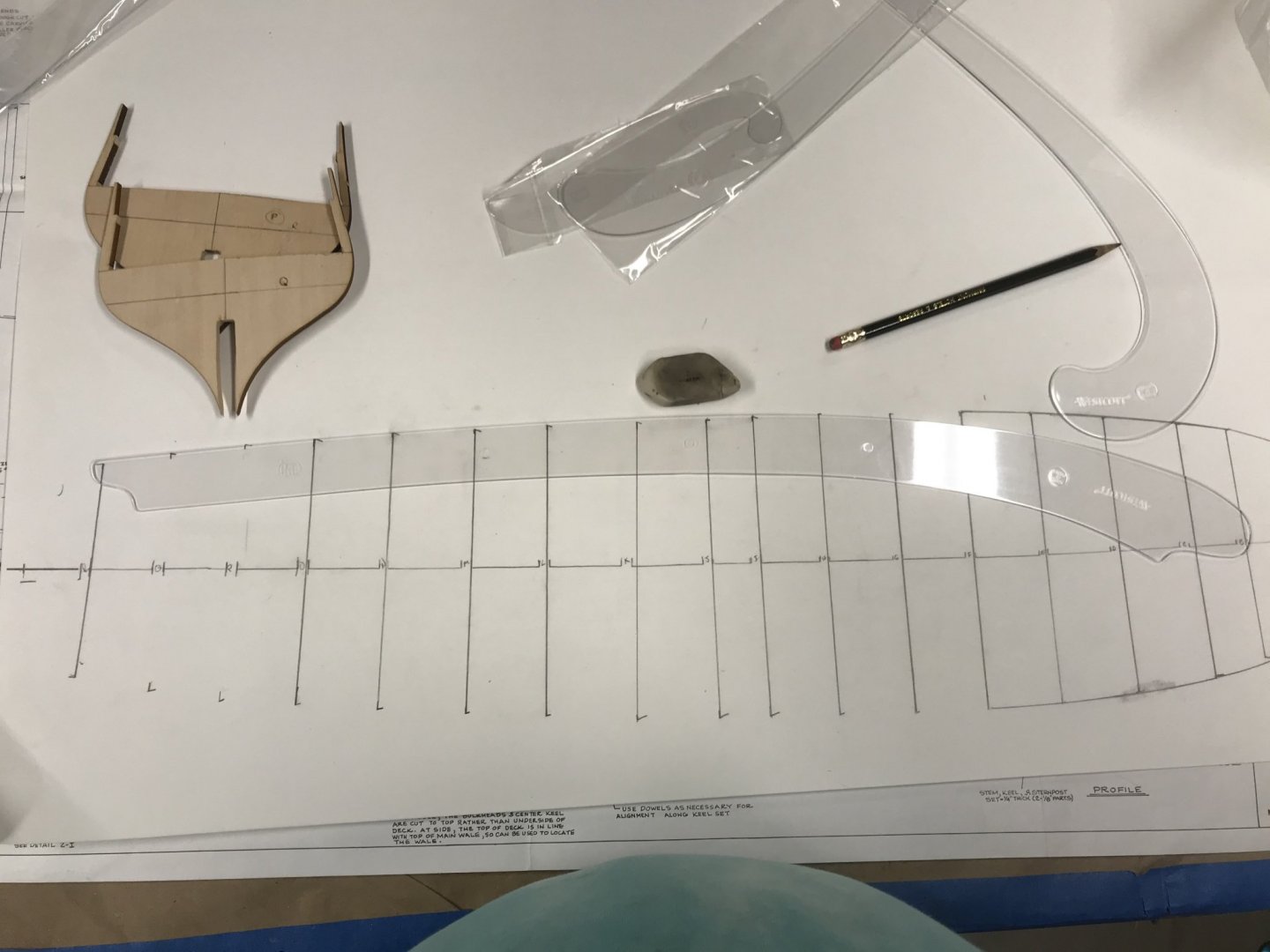
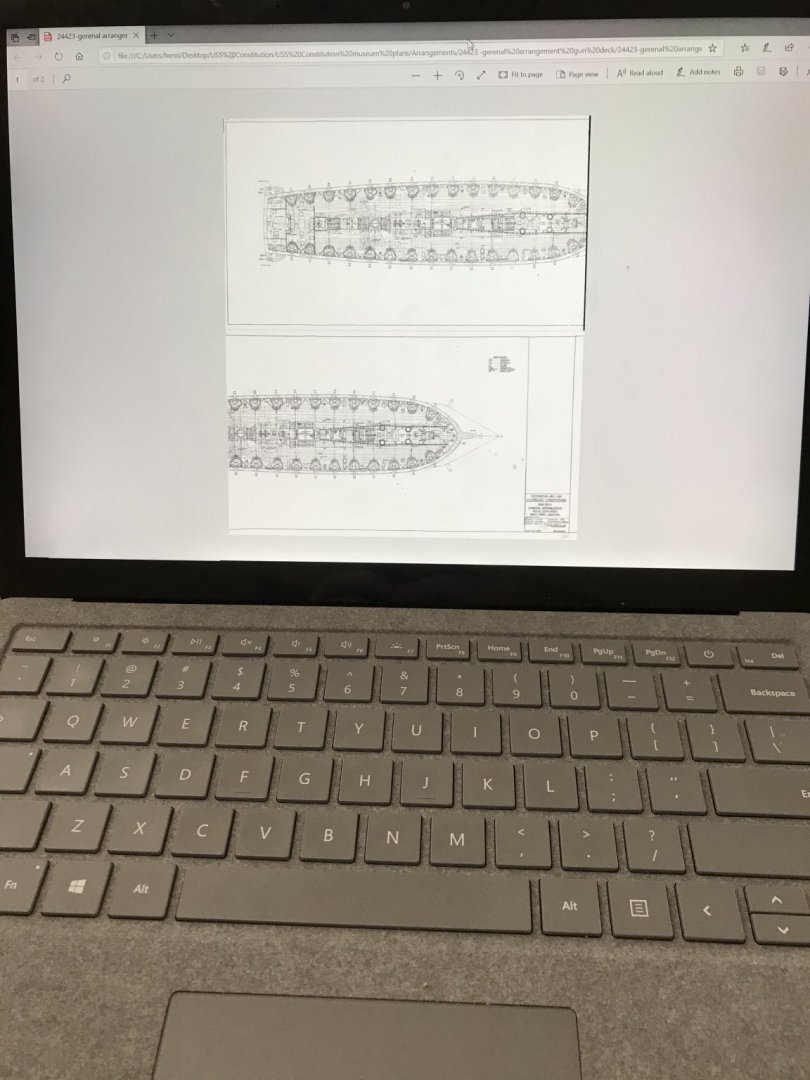
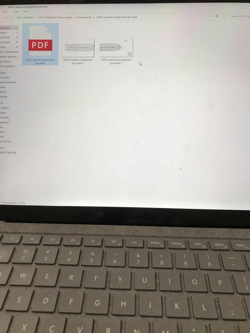
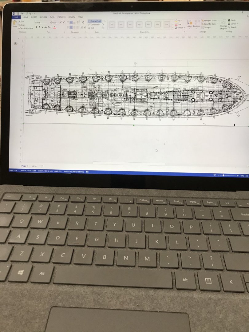
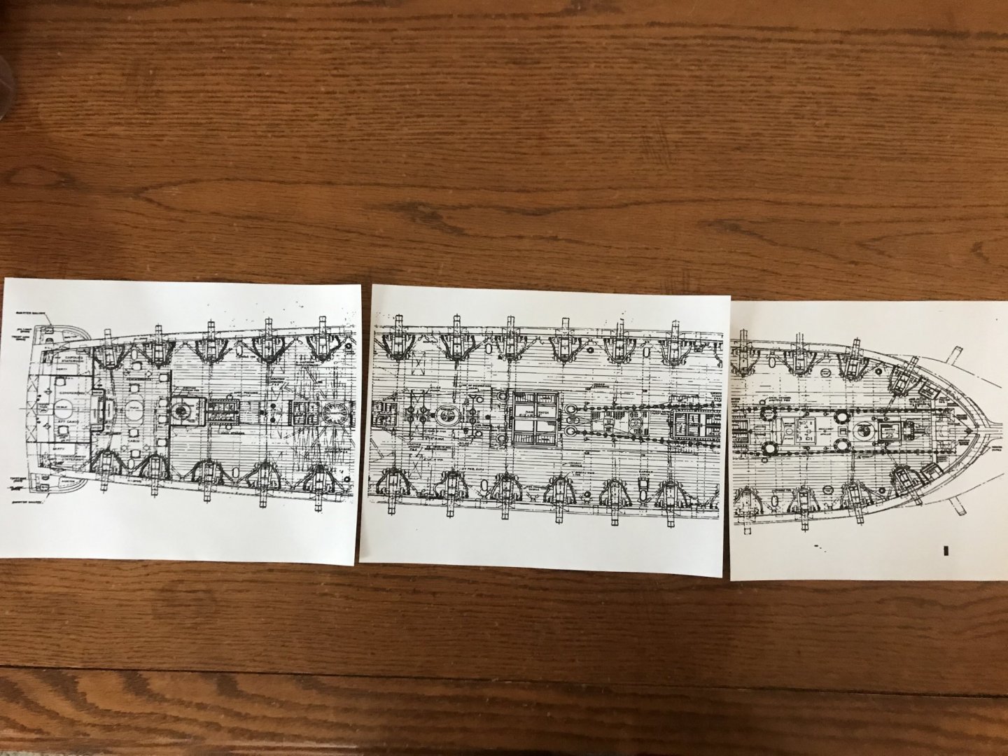
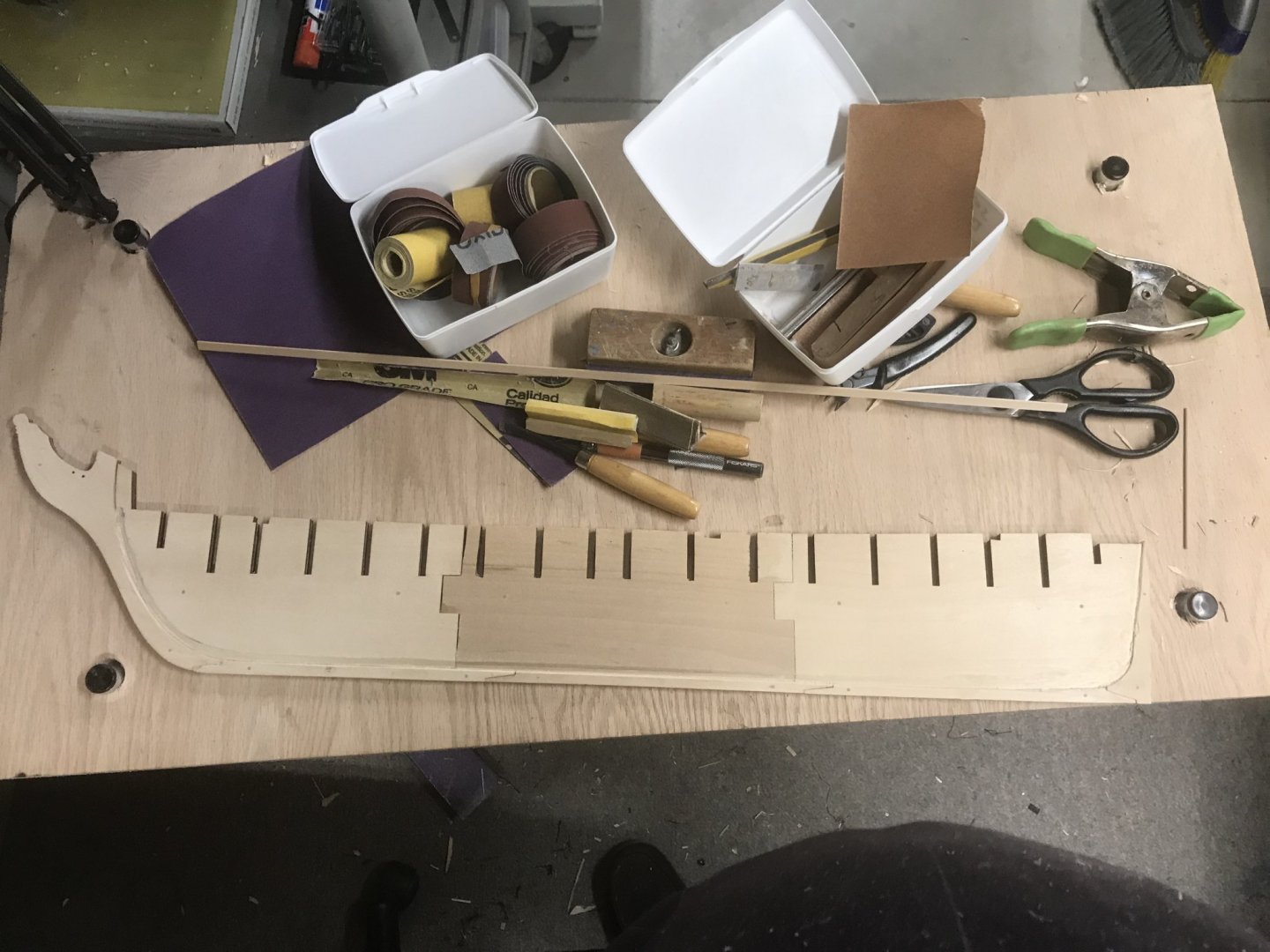
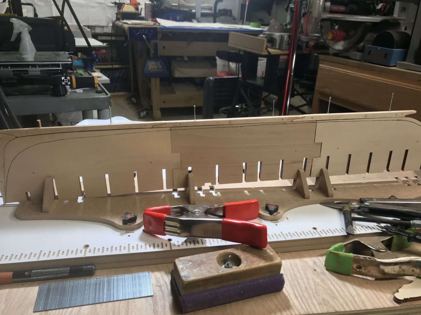
March 29, 2020 Since I have decided to fit out the gun deck, I wanted to show you my process for this thus far. On all the frames except A and B the spar deck support was removed. I also cut down each frame at the gun deck level 3/32" to accommodate the 1/32” sub-strake I plan to put in place to support the 1/16” thick decking. On a piece of poster board I drew a straight line and marked the locations of each frame. Since each frame had a center line drawn, I was able to transfer the distance from center of a frame to the inside gun deck location. This gave me an fairly accurate measurement of the deck from port to starboard at each frame . Once this measurement was recorded at each frame, I used my ship’s curves set to “connect the dots”. I need to mention that these are not a set of “French Curves” . Ships curves are made specifically for naval architecture. The curves are used for making lines and curves of the hull and the frames. I got my set on amazon for under $20. I can’t say that this is a must have for a kit builder. But, if you are a scratch builder, or a kit basher, then it is definitely a must have in the tool box. Once the dots were connected I cut out the pattern and test fit it to the model. I did this before the frames were glued in. The sub=strake doesn't need to fit snug, it just needs to be close as it’s purpose is to support the final decking. In fitting the card stock to the model, I realized that installing the sub-strake to the model in one piece could be challenging. I could do it in one piece, but I risk damaging the fragile posts on the side of each frame. The solution was simple, cut the pattern in half down the middle. Once satisfied that the fit was acceptable, I used the card templates to transfer my lines to the 1/32” plywood. Using my bandsaw I rough cut the pieces, trimmed them with the scroll saw, and finished the edges with my drum sander. The plywood is now ready for when the frames are glued up. After the sub-strake was readied, I realized that I will need to identify where all the deck fittings will need to go. A friend, who is also building the same model as I was recommended that I purchase the ships plans from the USS Constitution Museum. IT was well worth the $15. Included in the download are the plans from the 1927-31 restoration. The Constitution of today is basically the same as the Constitution of 1927-31. I am sure that there are some cosmetic differences, but these plans are good enough for my purposes. So I found the gun deck arrangement plans and converted them from a .pdf format to a .pang format. I brought these files into Visio. Then I measured on the kit plans the distance between the main mast and the mizzen and the fore mast. I also measured the distance from port to starboard at the main mast. This gave me five reference lines to downsize the museum plans to the kit plans. I cropped the image so that I only show the info that I need to print out. I printed the document on my printer. Trimmed and taped the pages together and then compare the print to the kit plans. I was pleasantly surprised that the print out was spot on. I will use this print to help me lay out the walls in the stern, the hatches, and any deck fittings.


-
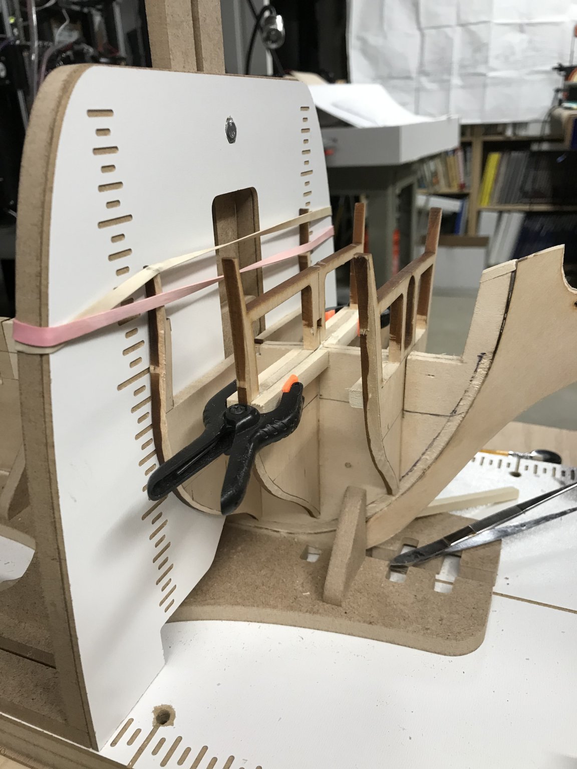
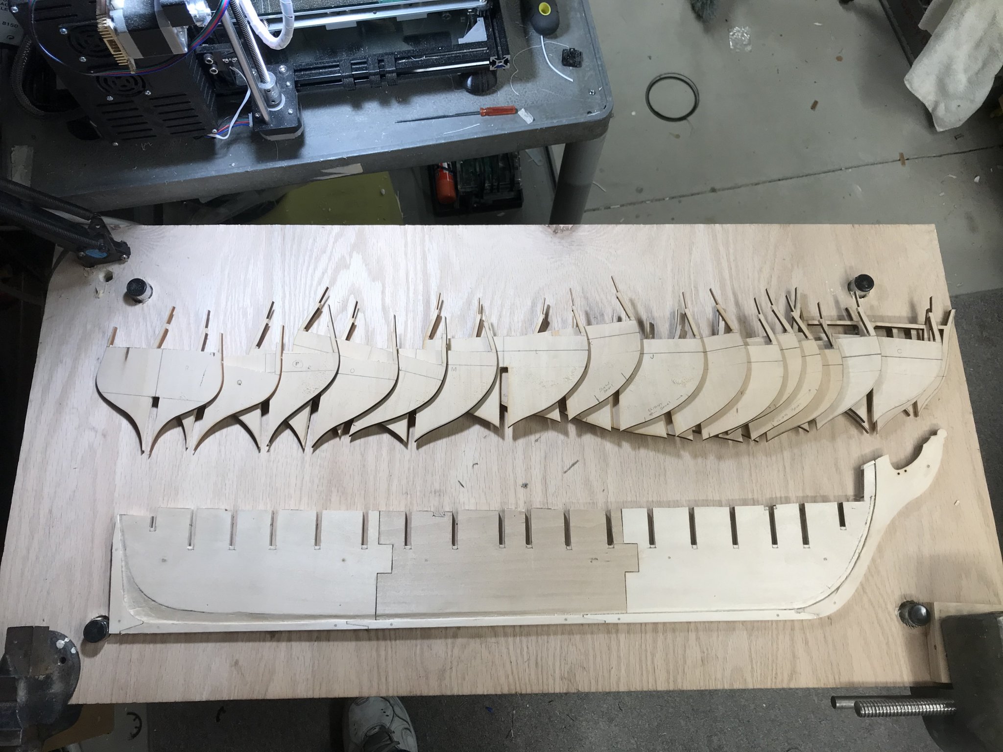
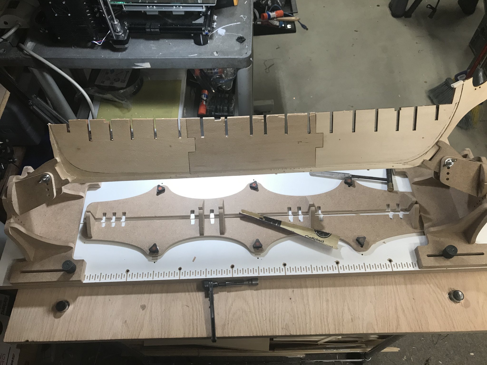
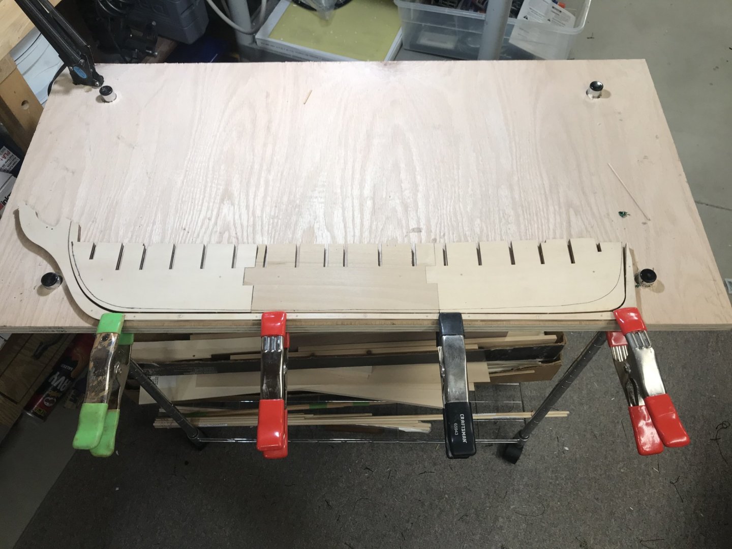
March 28, 2020 Today started the beginning of construction. I began with trimming a bevel using a #11 blade in my Xacto knife. You bevel the first seven frames and the last five frames. You do this before gluing the frames in place so that you have the basic shape done, then when the frames are glued up you can fine tune with a batten and a sandpaper block. A reference line was drawn down the middle and each side of the false keel , as well as each frame. This is done to help align each frame to the keel and to each other. Using my building slip, I started from the bow and worked my way backwards to the stern. The building slip has an attachment that allows you to square up the frame to the keel. This attachment has a sliding piece that centers it to the top of the keel. Here is my process. Apply glue to the frame slot and the keel slot. Insert the frame into the keel slot. Line up the reference lines so that the frame is perpendicular to the keel. Slide the frame squaring attachment of the building slip up to the frame. In some cases I had to use rubber bands to hold the top of the frame square to the attachment. Let the frame dry for about 30 minutes. Repeat the process for each frame. I was able to get eight of the sixteen frames glued up. While waiting for the current frame to cure, I started installing the support blocks of wood giving the hull lateral stability.


-
Henriy reacted to a post in a topic:
USS Constitution by Henriy - Model Shipways Kit 2040 - Scale 1/76
-
Thank you sir any advise is always welcome.
-
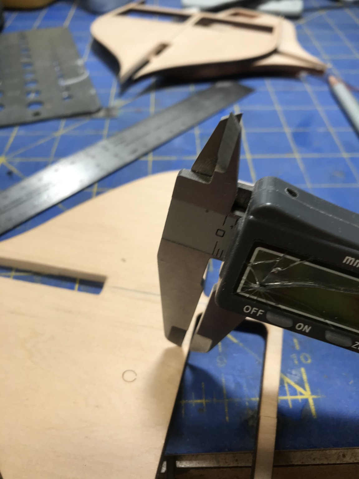
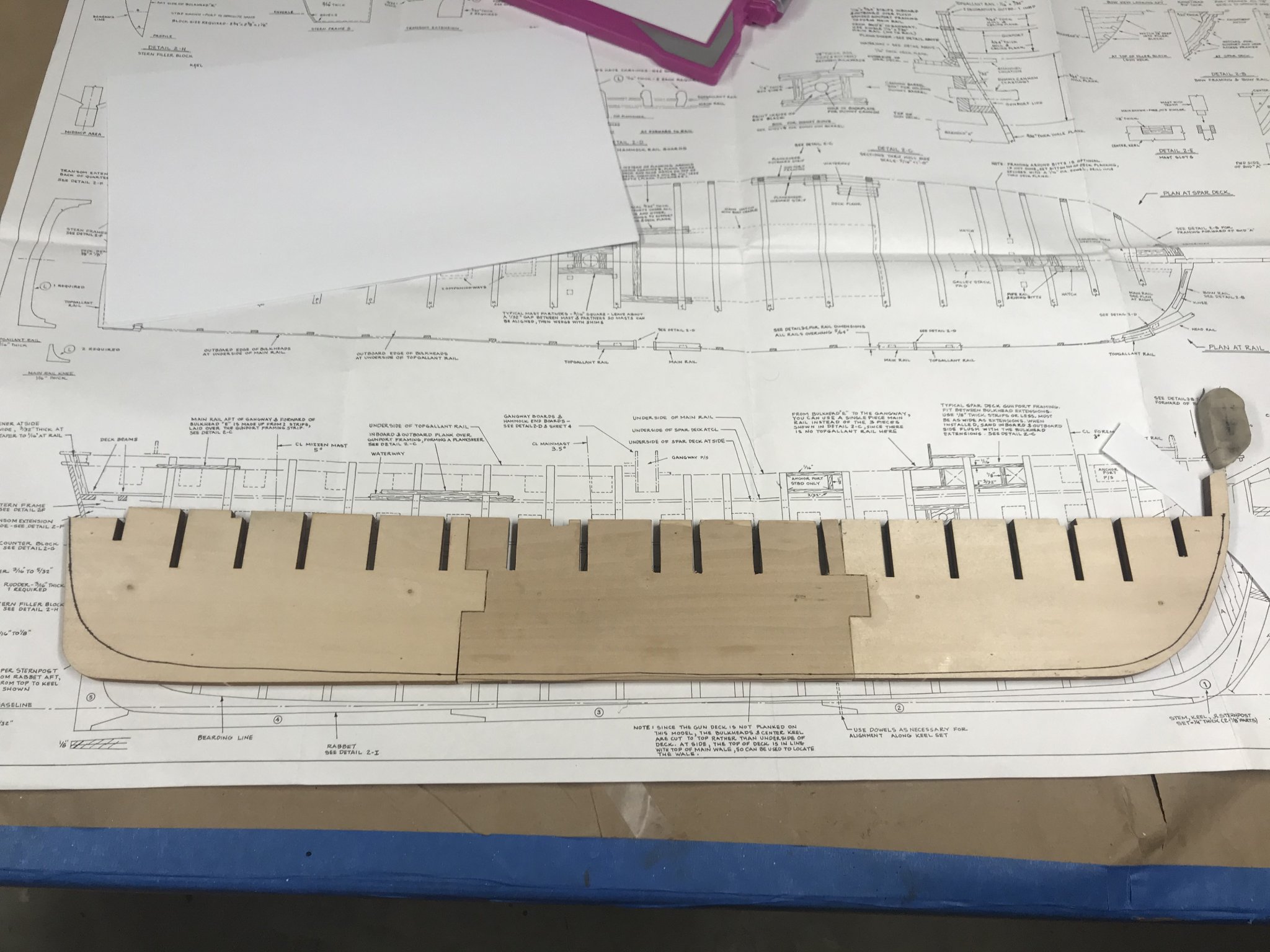
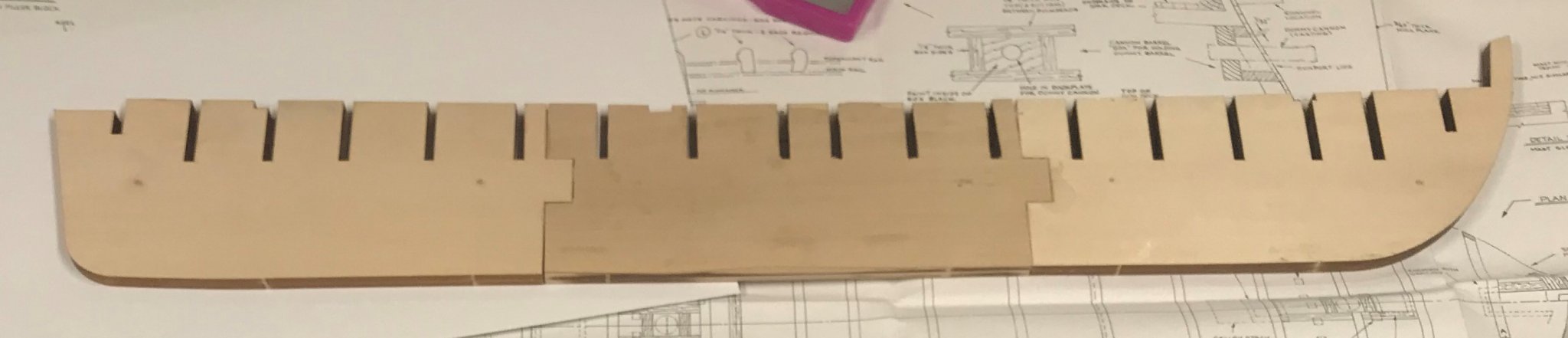
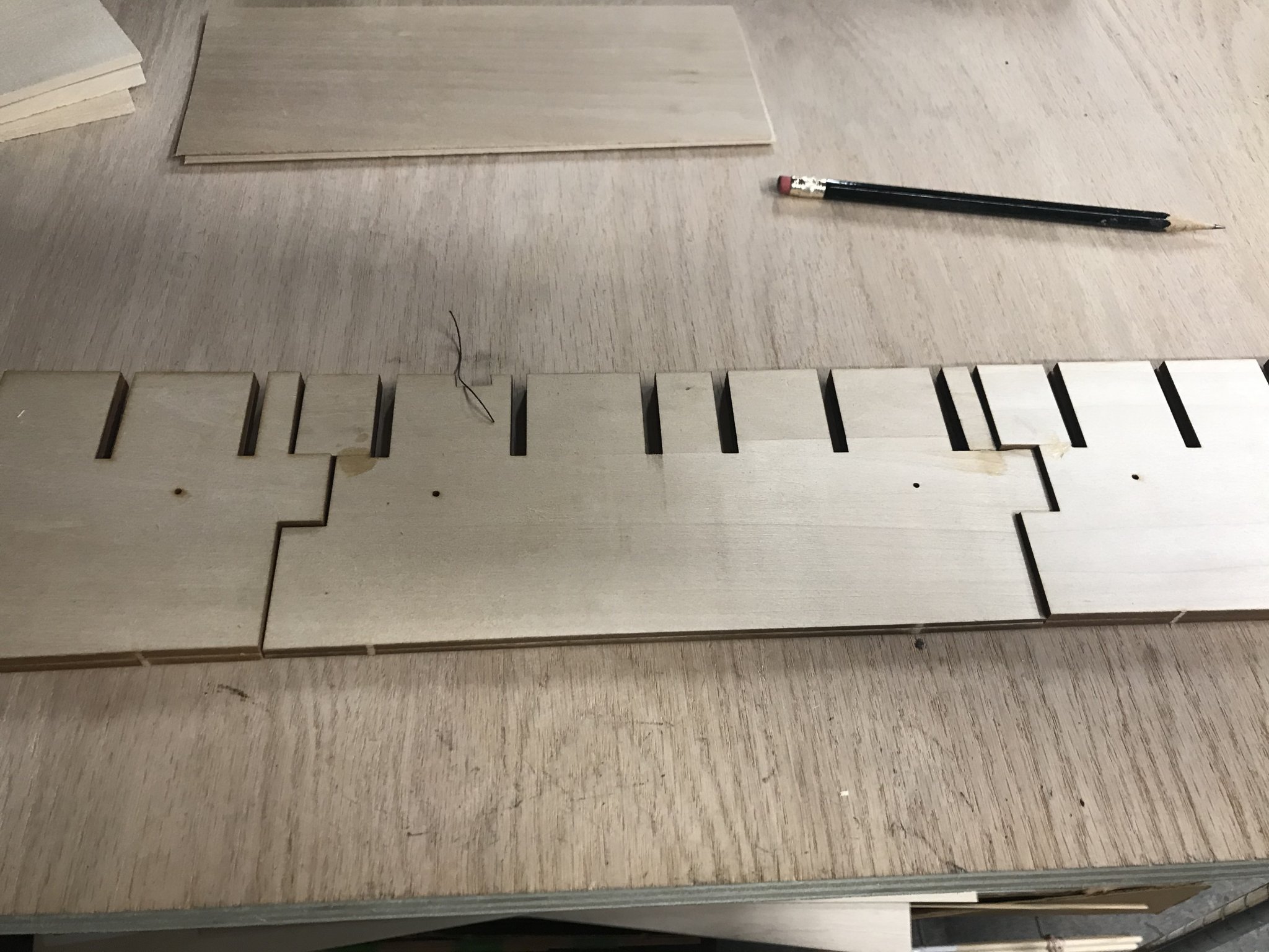
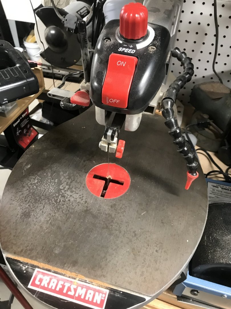
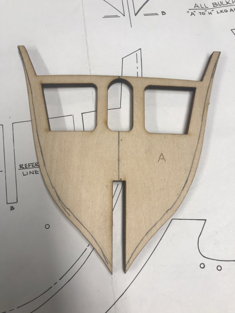
March 23, 2020 The weekend flew by and I hardly got to work on “Connie”. I did finally decide to build out the gun deck. I read up on JSGerson build log and took my cues from him. I first test fitted each frame to the false keel. Every frame was a tight fit. With the use of a file and sandpaper I adjusted the fit so each frame fits properly. Once all the frames fit, then I started marking up the frames to remove 3/32” from the top of the deck. Using a set of calipers, I set them to 3/32” and used them to mark indentations from the modeled deck. Then I connected the dots drawing a new deck line. This was done on all the bulkheads and the top of the false keel. Now comes the point of no return. Using my craftsman scroll saw, I trimmed off the 3/32” that will accommodate the 1/32” plywood sub-strake, and 1/16” decking that I plan to use. This was done on all the frames with the exception of Frames A and B. I need to read up on how JSGerson handled those. With all the frames finished, my next step will be to start assembly of the hull. More to come soon….


-
March 18, 2020 Tonight I spent a little time and finished the rabbet and bearding line on the port side. I worked the material the same way I did the starboard side. After I was finished, I mounted the end pieces to the building slip and slid the assembly in the jaws. What I really like about the building slip is that I can rotate the model 180 degrees. I can’t wait to start planking and using this feature of the building slip. Again best $65 plus shipping that I ever have spent. Tomorrow I start planning out the gun deck and figuring out how much material to remove to make it happen. I definitely will reread some of the build logs already done to help me figure this out.


-
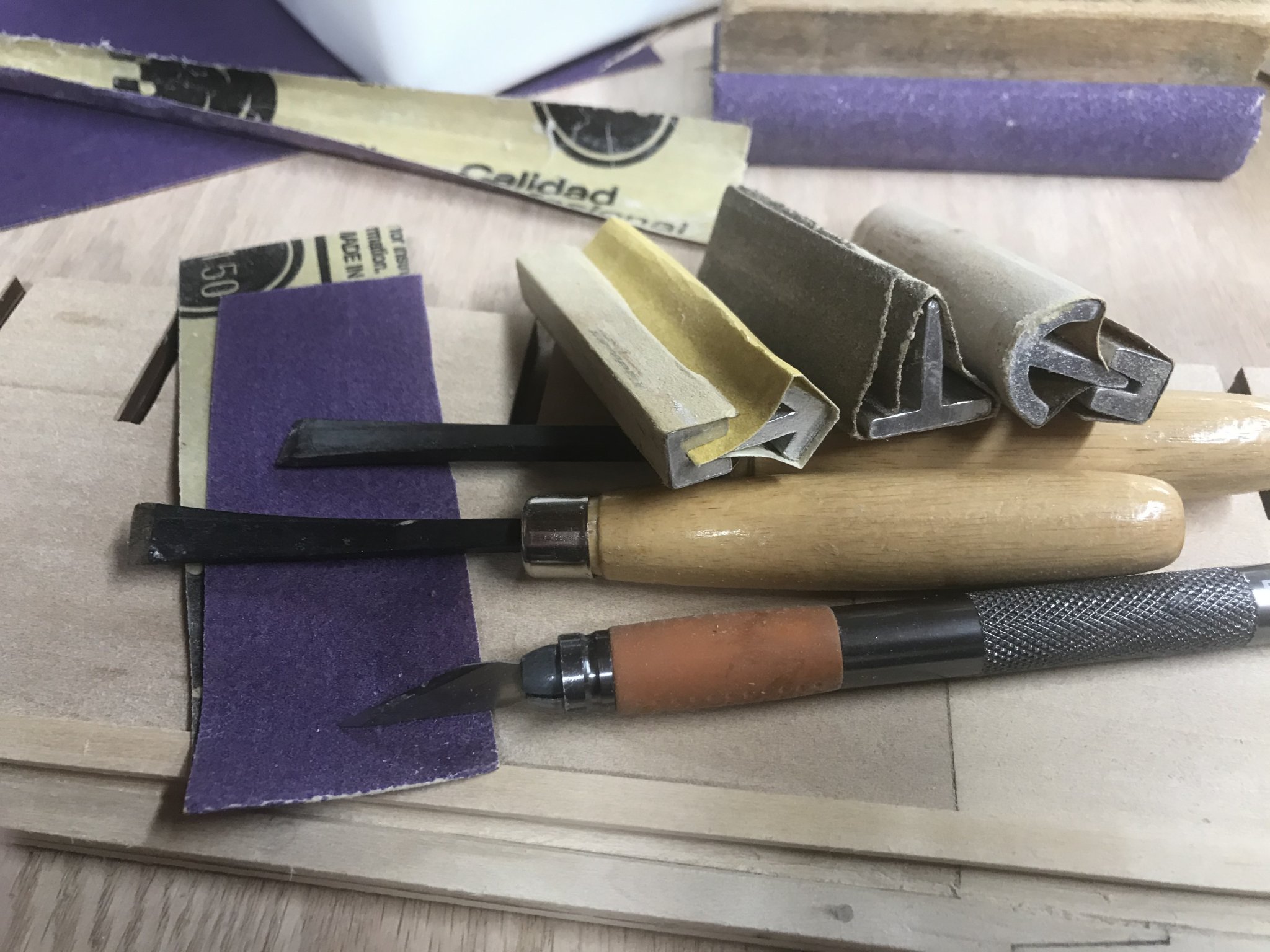
March 17, 2020 Tonight I didn’t have a lot of time to devote to the project. I did manage to get the rabbet and bearding done on the starboard side of the Keel/False keel assembly. I started with my x'acto knife with a #11 blade in it. I cut along the bearding line starting at the bow and working my way astern. Then using my set of chisels I carefully cut away the material from the bearding line to the keel. I kept in mind the angle and periodically checked my work with a plank. Once the removal of the material was completed, I gout out my sanding blocks and started to fine tune my rabbet. The sanding blocks I use I had gotten them from Micro Mark many years ago. I use sandpaper that has adhesive on the back and do my best. Like I said I got the starboard side done tonight, tomorrow I will do the port side.

-
Henriy reacted to a post in a topic:
USS Constitution by Henriy - Model Shipways Kit 2040 - Scale 1/76
-
March 16, 2020 While the rest of the world shelters in place, I got the opportunity to work from home for eight hours. Then I spent some time with Connie (USS Constitution). Today’s to-do was to attach the keel to the false keel. Boy did my building slip come in handy for this. I removed the front and tail piece, plus the bulkhead holders. This left me with the Keel holder. I flipped the false keel upside down, and secured it to the slip. Starting at the stern, I placed the keel on top of the false keel. With the help of a couple of clamps, I started to drill out the holes for doweling. Three dowels in the Stern post, then six more in the keel. I drilled the holed through the keel and stopped. Then I used nails to mark the holes. I do this because sometime when using a pin vise the drill but tends to stray off the mark. By tapping the nail with a hammer, I mark the location of the hole to be drilled. Then I finish drilling making sure that the dowel goed past the Bearding line. The same is done for the stem/Bow. I prep the dowels by cutting them to length and trimming one end into a point. Then I hammer the dowel in just enough do the tip poke out of the hole. I test fit, and make any adjustment. Finally I glue it up and tap the dowels home. I use some clamps to pull it altogether tight and let the glue dry. The same process is done for the stem/bow. It’s a little trickier as you have to deal with curves. I didn’t spend a lot of time on this, about an hour or so. I am satisfied with the results. The next to– do is cutting the bearding line and preparing the Rabbet line. We will do this tomorrow…..or when I can get back to this.


-
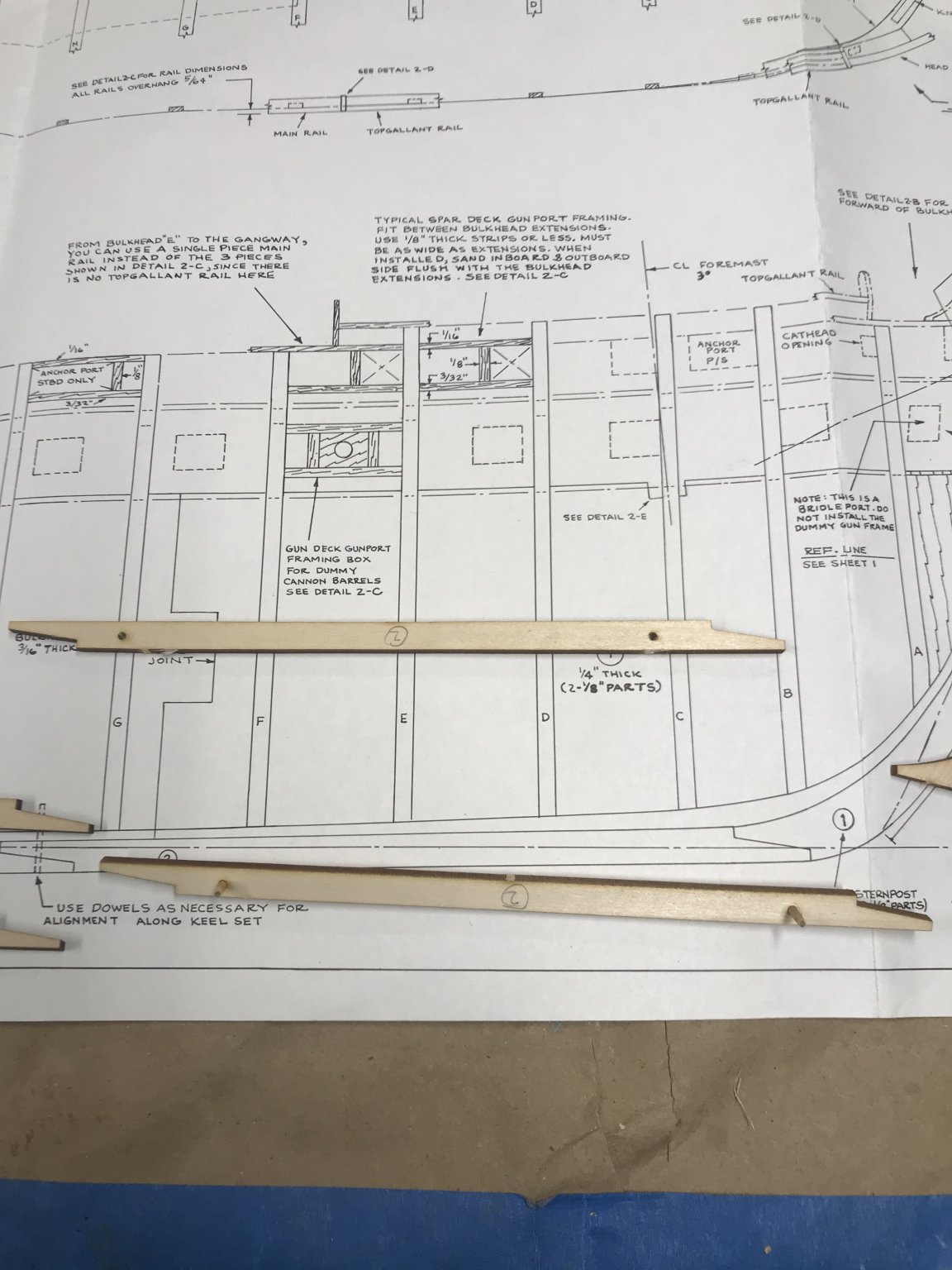
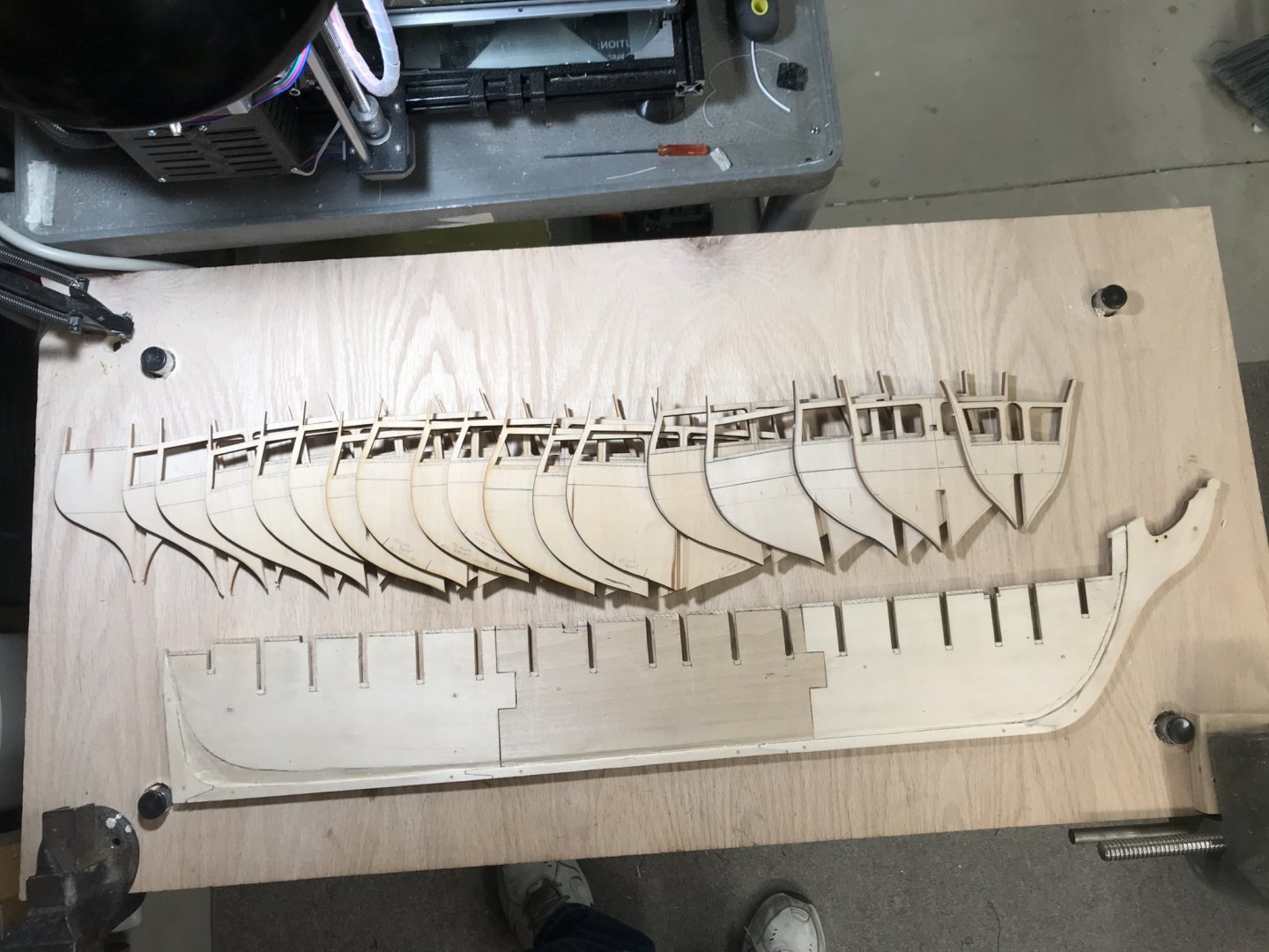
March 15, 2020 I didn’t get as much done as I wanted to. I started out my morning with trying to untangle a spool of rigging thread so that I could transfer it over to a thread bobbin that I 3D printed. I am trying to get my workshop organized better so any loose rigging thread gets spooled up. Right when I am about to get to work, the CFO calls me and wants me to run some errands. So I did. I got back and finally got some progress done. Since the Bearding line was done on the false keel, I figured I should start working on the Keel of the ship. After I cut the parts from the wooden frames, I line them up on the plans and numbered them. I also marked them with a “B” for bow on the front end of each piece and an S for stern on the back end . I did this because the center piece of the keel look the same, but they are not. I didn't want to make a mistake that I would regret later. The keel in this kit is in two parts that are glued together. I used small dowels as pins to line up the pieces so that gluing process would yield straight pieces. With each of the keel pieces the Bow/Stem and Stern post glued up, I then decided to dowel and glue them together. The glue I use is very strong, but adding the dowels add strength and helps keep the pieces straight. All pieces are glued up and clamped to my straight board. The picture shows the false keel in place. It isn’t glued the keel yet.


-
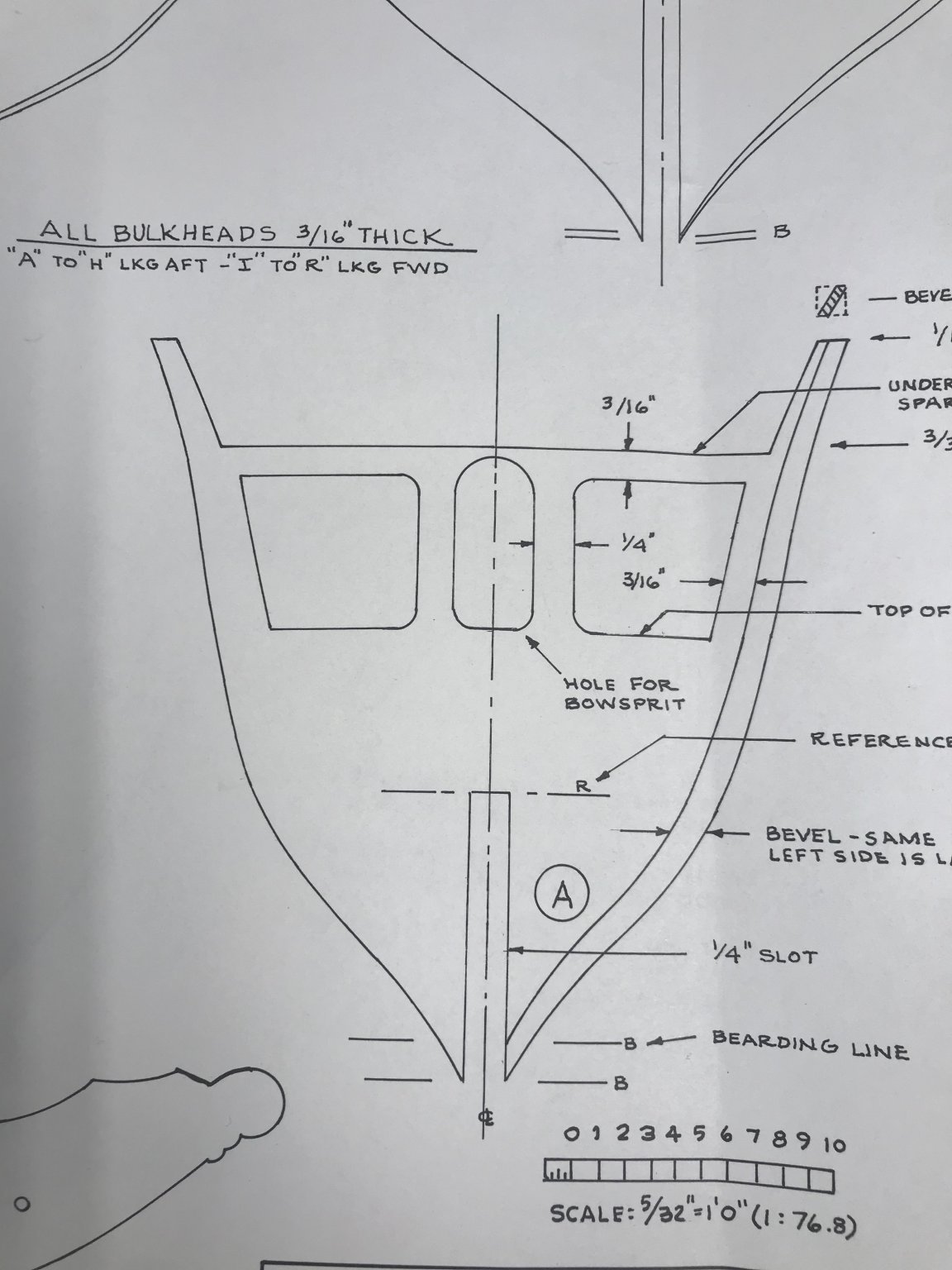
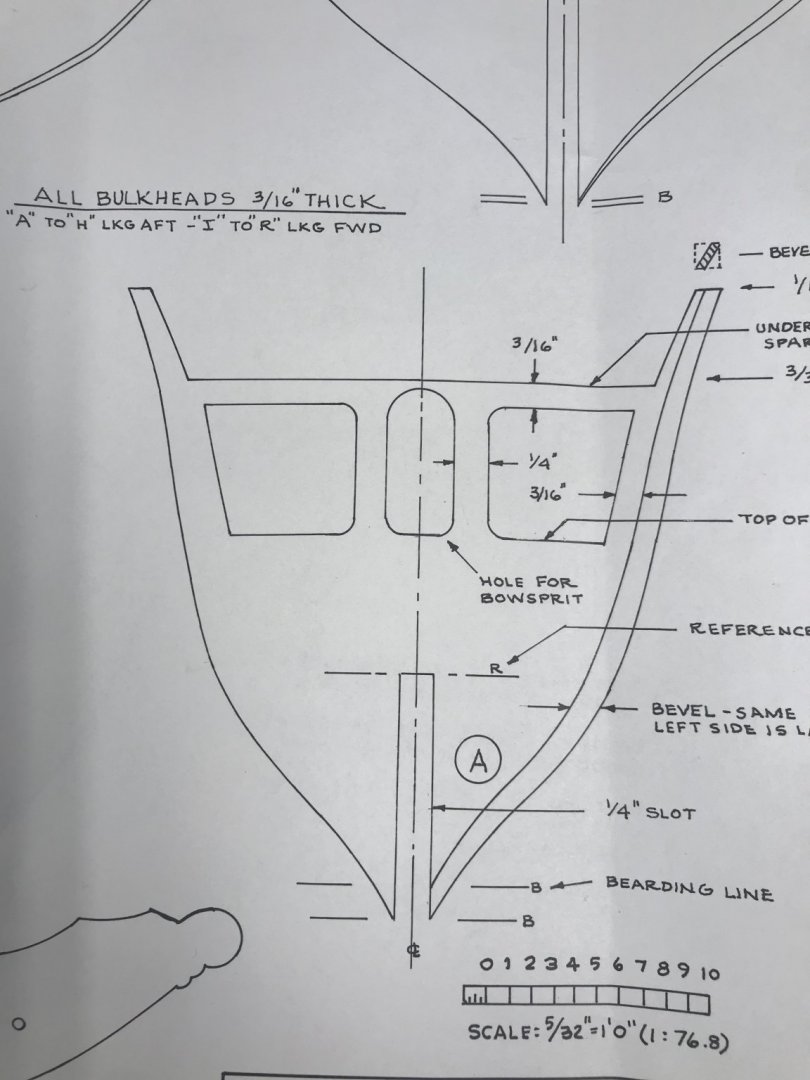
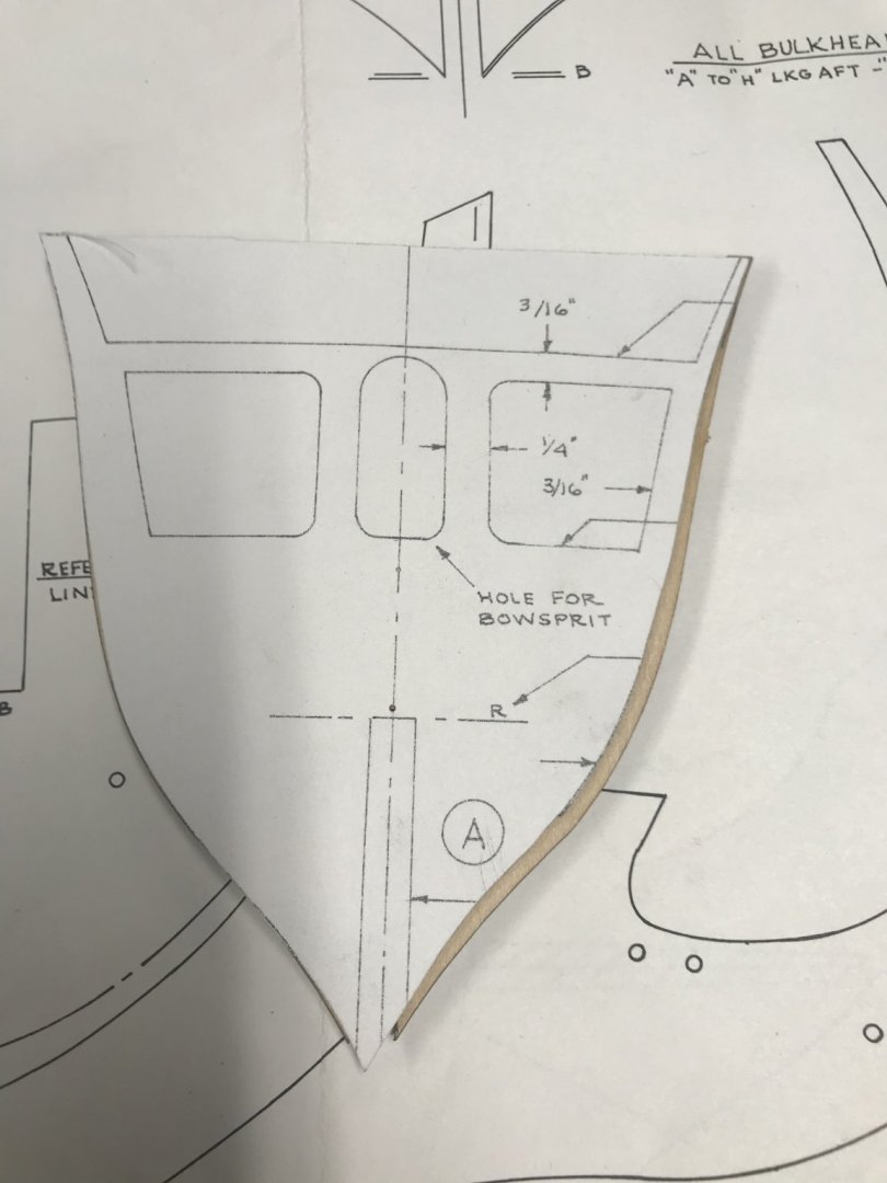
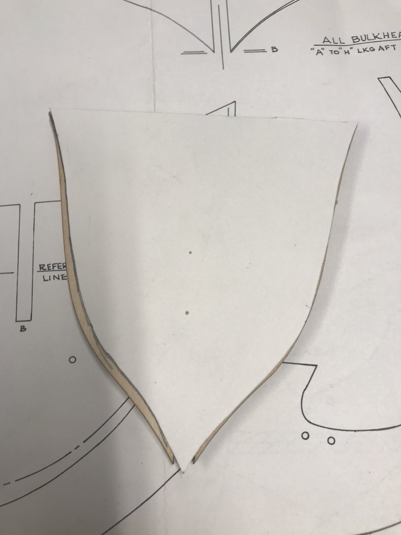
March 14, 2020 Why does work have to get in the way of life??? Anyways, today I got to actually do some real work on my USS Constitution. I put my All in One printer to work. I needed to make templates for fairing my frames as per the instructions. Like the frames templates they are glued to posterboard. I made a copy of Frame “A” and cut it out and then compared it to the plans and the wooden frame that came with the kit. The copy was spot on, so I didn’t have to worry about issues with my copier. The plans show the frames with what I call suggested fairing lines. For you newbies out there, fairing is the process of shaping your frames by removing material so that when you are planking, the planks lay flat against the frame. If you are new to planking I highly recommend downloading this pdf https://modelshipworldforum.com/resources/Framing_and_Planking/plankingprojectbeginners.pdf . This document will answer all your questions about planking your model. I have been building for 35+ years and I keep this handy so I can refer to it during my build. With the fairing templates made, I then transfer the lines to the wooden frames with a SHARP pencil. The templates are made on the left side of each frame as the fram is out of the box. However on the right side is a second line running parallel to the side of the frame. This is the fairing line. I cut the template on the fairing line on the right and the standard edge on the left. I then take the template and line up the left side of the template with the left side of the wooden frame, and trace the fairing line. Then I then flip the template over and align the right side and do the same on the left. Only a handful of frames have fairing lines. Frames A through K, and frames N-Q. The Bow and Stern of the ship of course. Now earlier I said these are suggested lines. DO NOT CUT OR MODIFY these frames until you have the frames attached to the false keel and are ready to “Fair” your hull. I also drew the most important of reference lines, the center line. I did this on every frame using a zeroing ruler. This is a ruler that has zero in the center and increments by inches on either side of the zero. When you put the ruler between two points like the edges of the frame you can determine where center is pretty quickly. Two centering points and line em up with the ruler edge, and draw your line. Do this to each frame until all have a centerline.

-
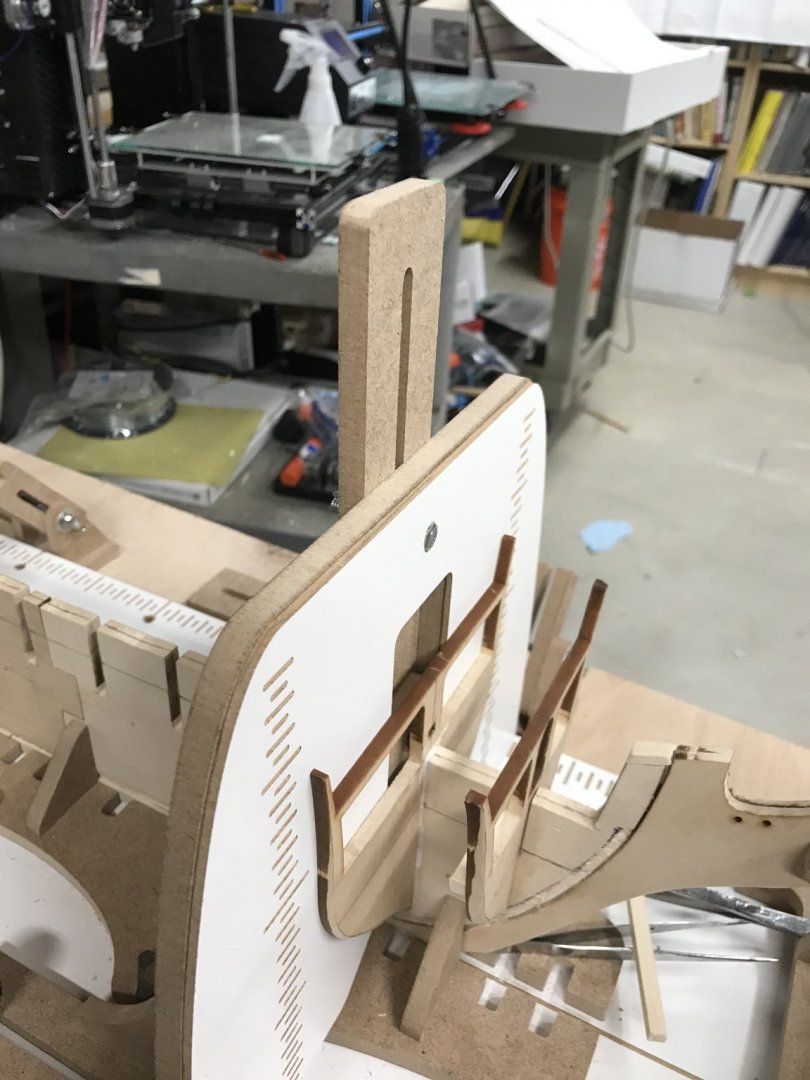
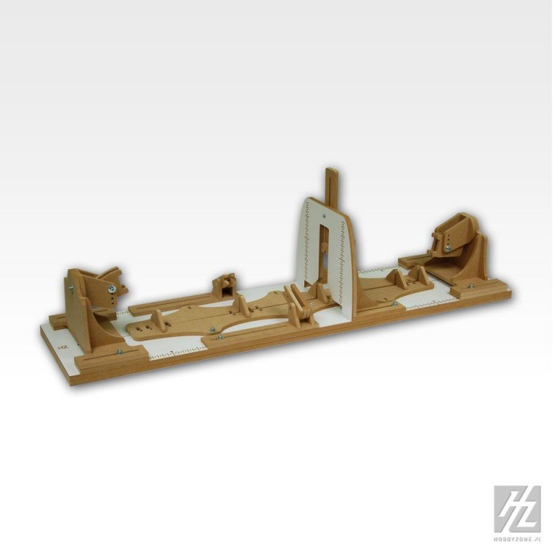
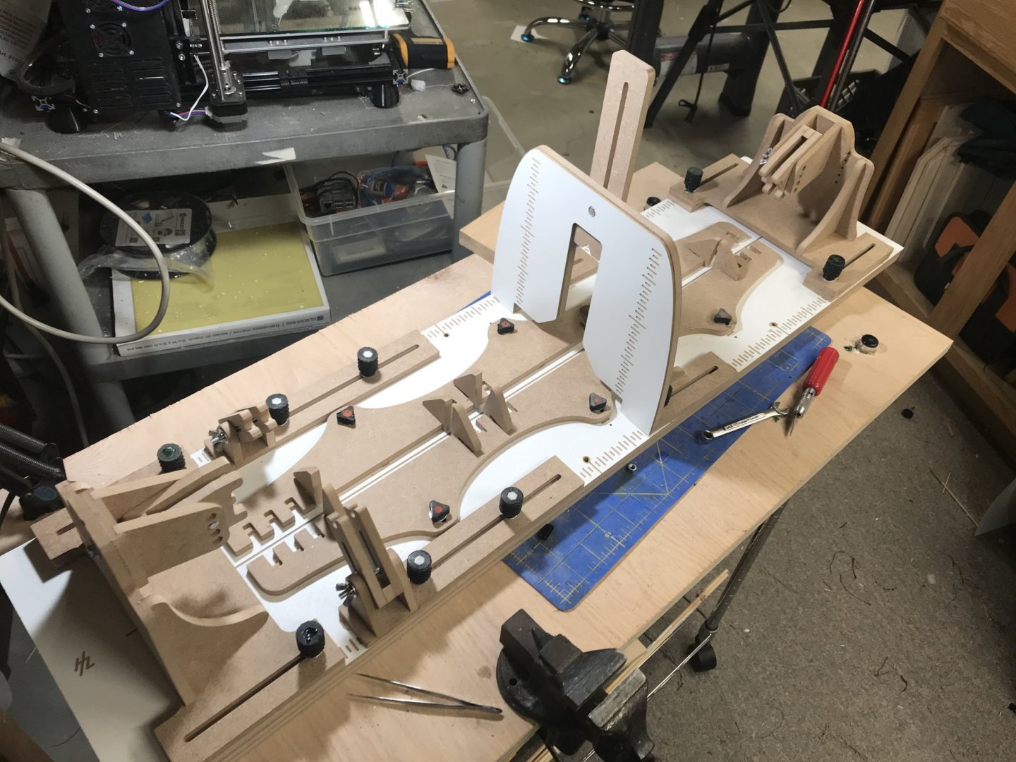
March 11, 2020, I am back from my trip to El Paso. All the work stuff was successful, and I got to go home. I arrive home and waiting for me is my other Christmas present to me. A HobbyZone Professional Building Slip. Back in January I was perusing the Model ship world site and ran across an article written by James H. I read through it and realized it is a must have. In the past I have used pana-vises, and building cradles made of plywood. Nothing that compared to this. I got my credit card, found the Hobby World USA website and ordered it. Unfortunately it was out of stock…..ugh. But I really wasn’t ready for it as I was still working on my USS Constitution cutaway model. So I waited, and waited, and waited. The folks at Hobby world USA were great about keeping me informed. They order directly from the manufacturer in Poland, and they didn’t have any ready for shipment. Finally they did and mine arrived. I recommend looking at James H’s build/review if you are looking for a platform to build your ships. I took it out of the box and started to put it together. I will tell you right now that the included instructions are awefull. My recommendation is to print out Jame H’s review and use that as the building instructions. After I got it built I made some improvements courtesy of my 3D printer. I went to Thingyverse.com and searched on 5mm knobs. I found a whole bunch and printed some test samples of what I thought would work. I ended up using a Knurled Knob and a low profile triangle knob. I had to replace the bolts with longer ones which I happened to have in my stash. I had to buy a couple of M5x55 bolts for the end knobs and wing nuts from Home Depot. I have included a picture so you can see the results. That’s all for now my next post will be about my Connie build.
-
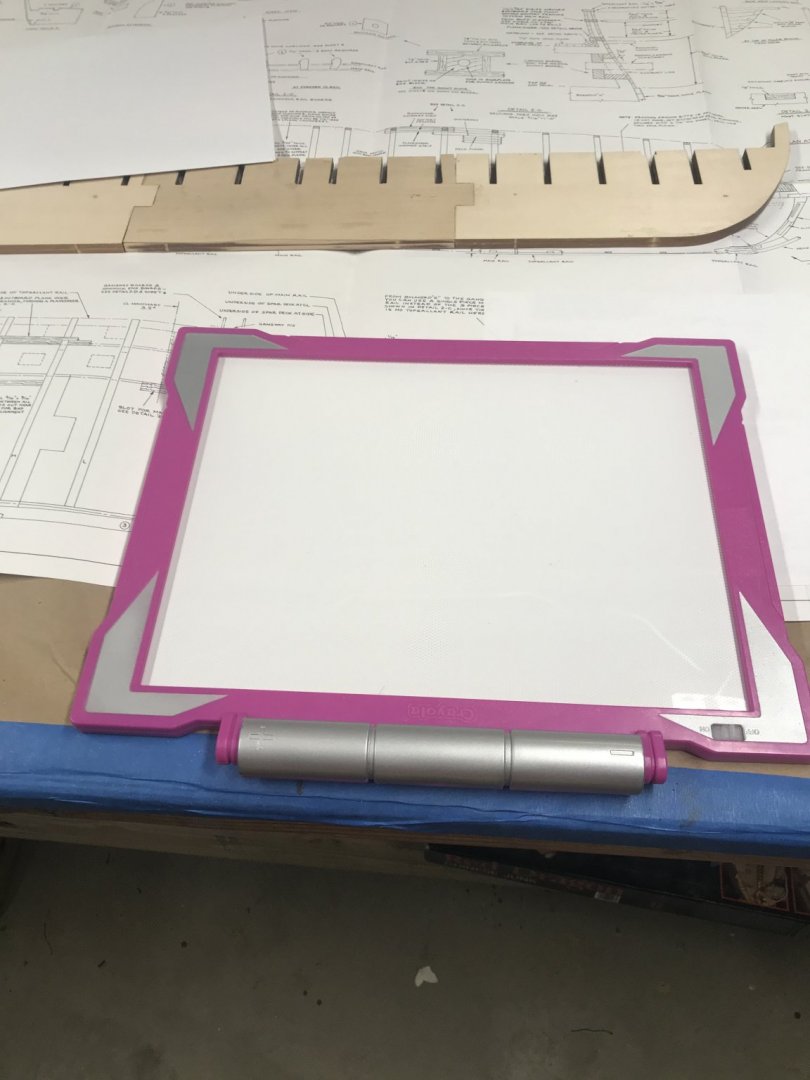
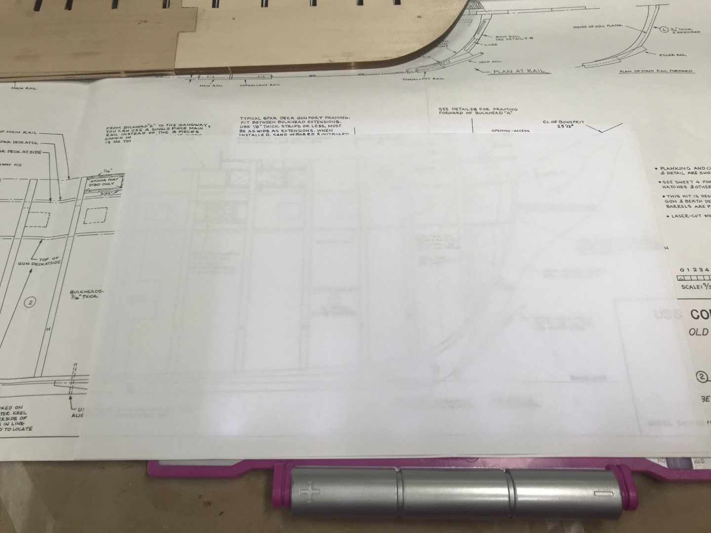
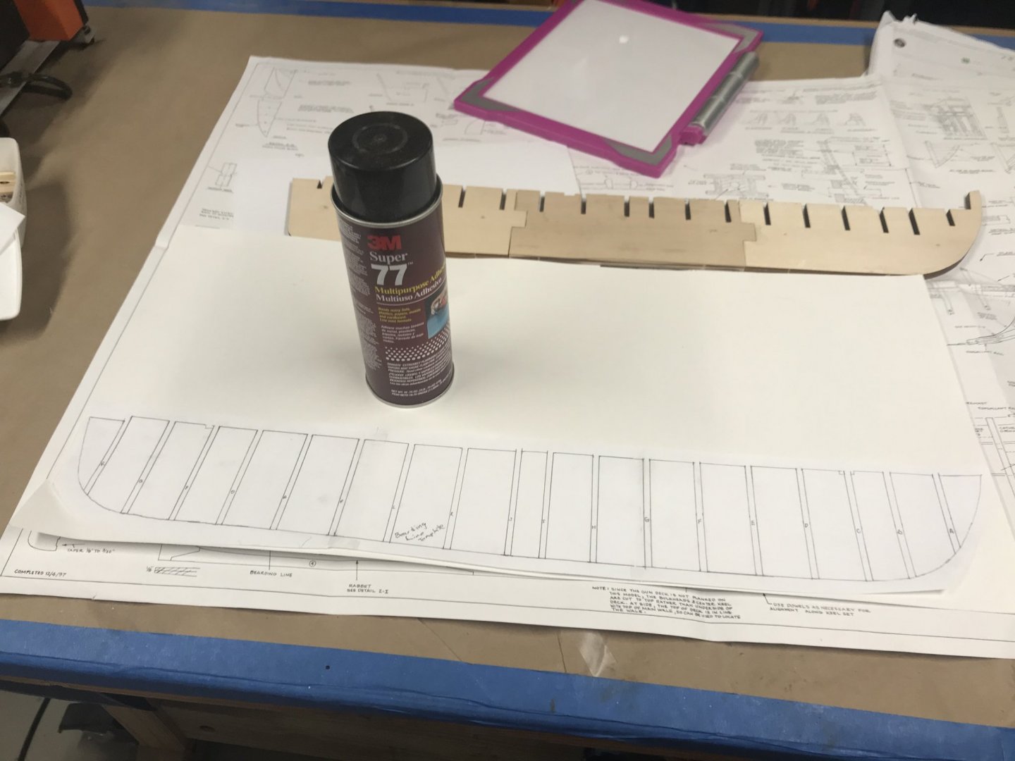
March 3, 2020, 6:30pm EST To layout the bearding line I chose to make another template. Originally I was planning to get my sheet plans copied at Office Max. I found out that they practice in highway robbery. The cost to get each sheet copied, save digitally, and printed cam out to almost $90. So I opted to make my bearding line template the old fashion way. I borrowed my 9 yr. old daughter’s tracing light. With this tool and a sheet of copy paper I traced out the bearding line on the sheet plans . When finished I taped the tracings together, overlaid them on the sheet plans to make sure it was correct. Then I got out the can of spray rubber cement and sprayed down the back of the template and applied it to a sheet of poster board. Once I cut it out, I placed it on my false keel and traced the bearding line to both sides of the false keel. With that completed, I shut down my workshop until I return from my trip.


-
March 3, 2020 I don’t have a lot of time today because tomorrow I have to go to EL Paso for a week for business. However any time spent on the model is time well spent. So this morning, I glued up the three pieces of the False Keel Together. Let them dry while I am at work tonight I will lay out the bearding line


-
March 2, 2020 Assembly of the false keel starts. Much to my surprise the center section of the false keel is thinner than the bow and stern sections. I triple checked the instructions, and some build logs of others who have built the same model. I didn’t find any references to the same issue. As you can see in the pictures, the center section is 1/32” thinner than the adjacent pieces. So to remedy this, I went to my scrap box and found a sheet of 1/64” basswood. I laminated a piece to each side of the center section and then trimmed out the notches. Now the center section is the same thickness as the bow and stern areas. With this kit defect fixed, I was able to move forward with the building of the false keel.