HOLIDAY DONATION DRIVE - SUPPORT MSW - DO YOUR PART TO KEEP THIS GREAT FORUM GOING! (Only 20 donations so far - C'mon guys!)
×


HakeZou
-
Posts
325 -
Joined
-
Last visited
Content Type
Profiles
Forums
Gallery
Events
Everything posted by HakeZou
-
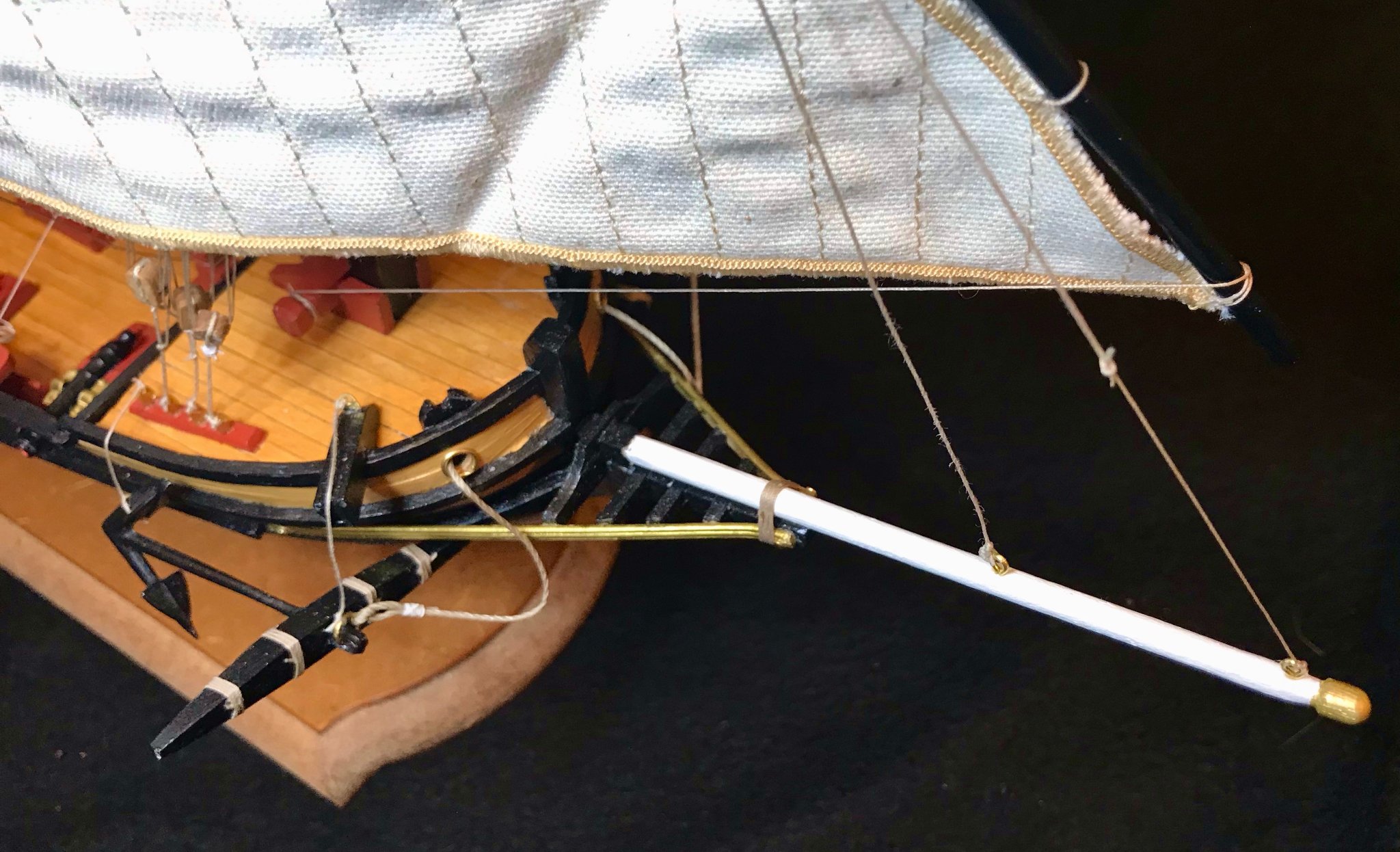
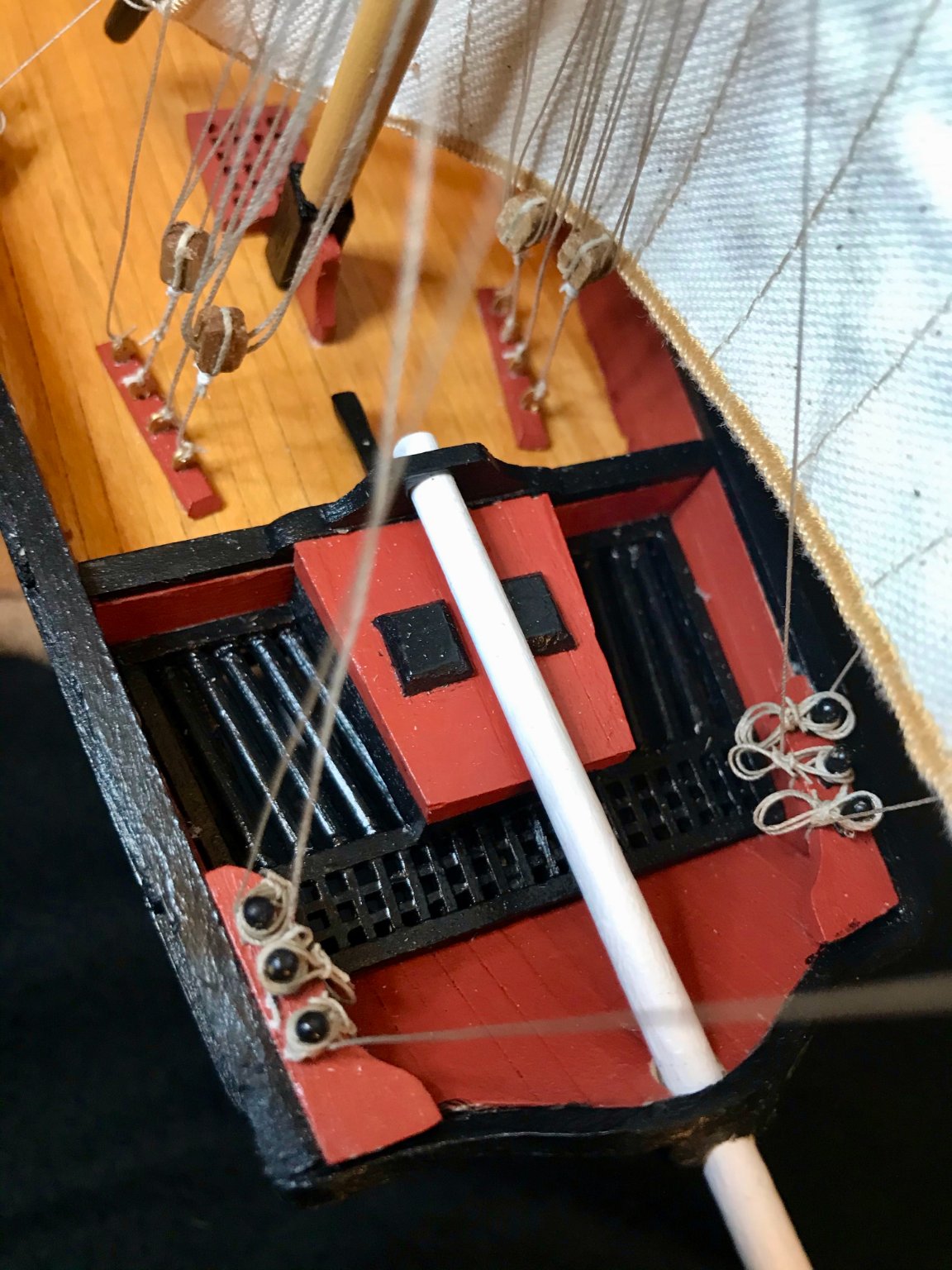
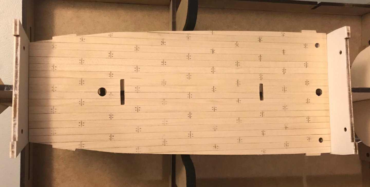
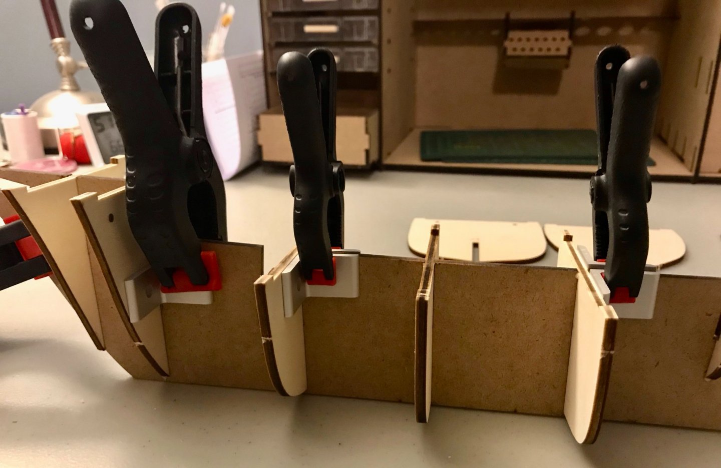
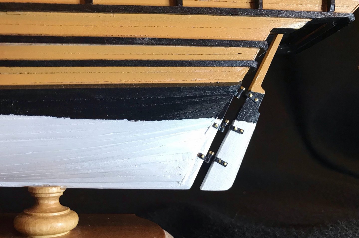
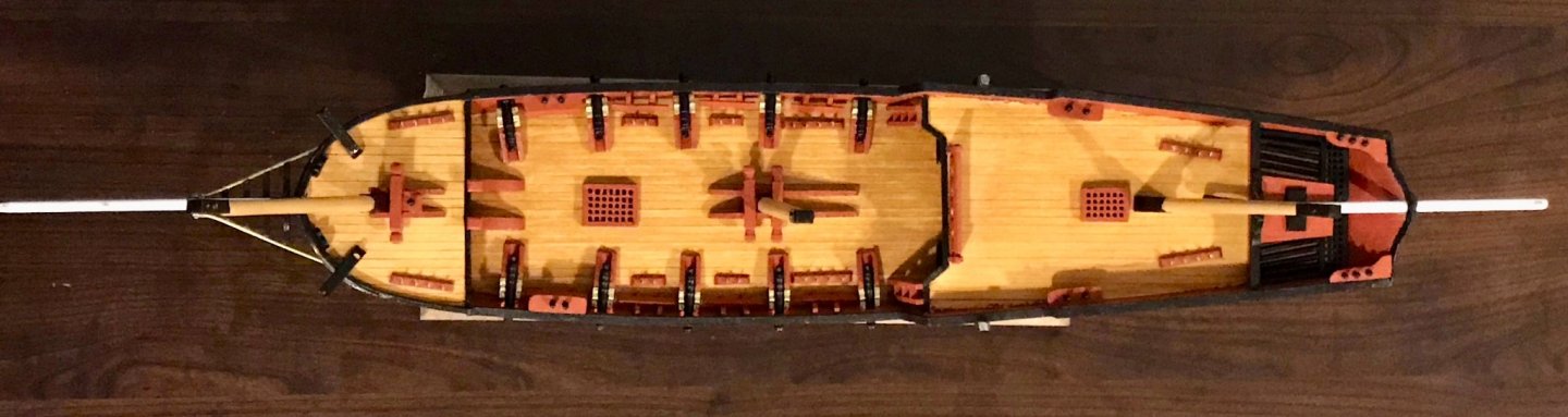
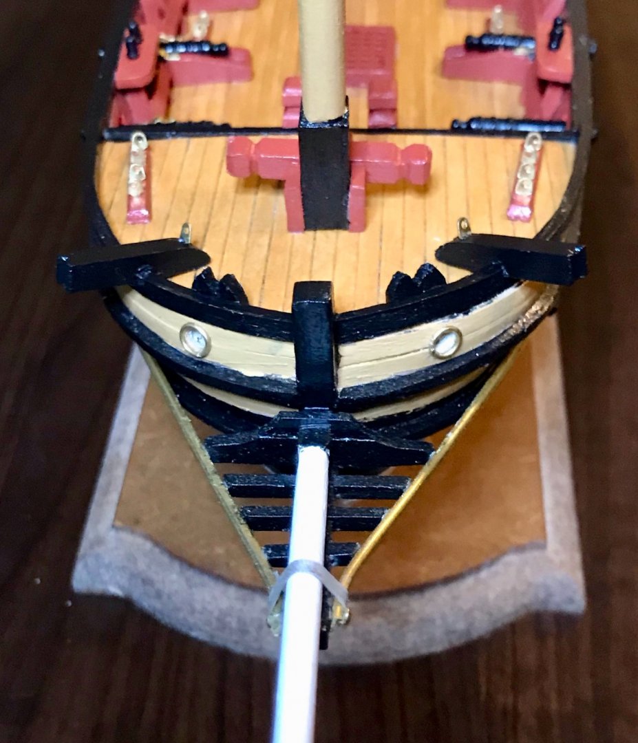
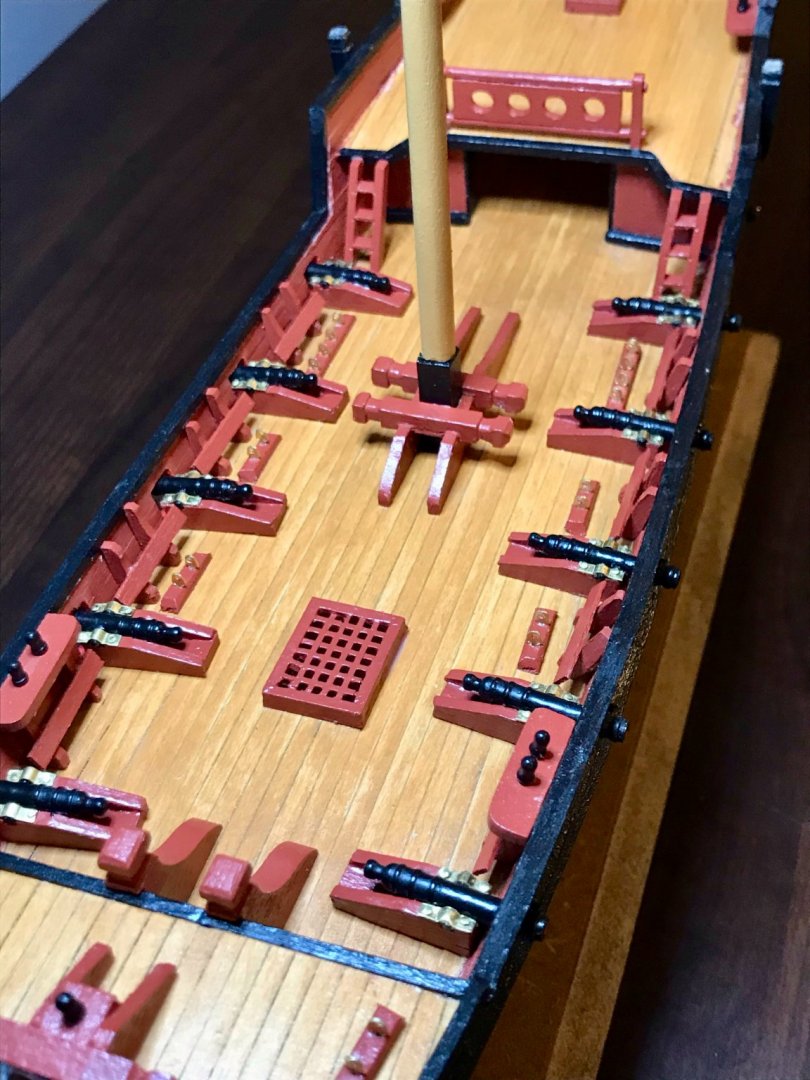
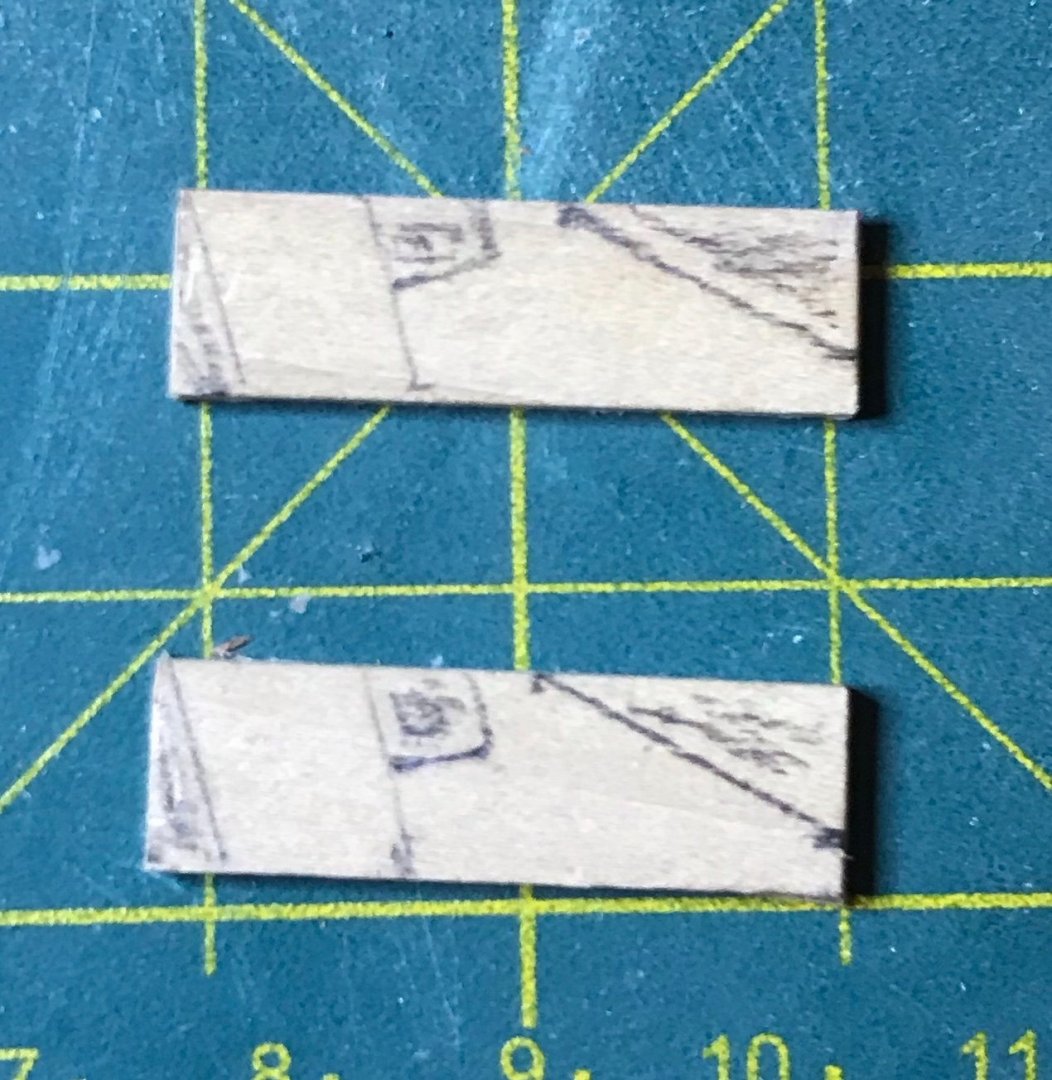
Tonight, I finished the "A" steps of the Endurance. After installing the frames, the next step is to install a few blocks that will help when it comes time for planking. There are two on each side at the bow and two on each side at the stern. I decided to sand off the excess char on these blocks and now regret that a little. Apparently, I took off a more than just the char, since there are some sizable gaps (especially at the stern). Although they don't seem to be cut as accurately as the frames were, they did fit a little more snugly before I went after the char. Photos are of the blocks, portside view of the bow blocks, overhead view of the bow blocks (with a gap for the bowsprit), and portside view of the stern blocks. The last "A" step is the main deck. Johnny's comments above are a propos here. The planks are much too wide for the scale (5mm scales up to 3.5m!). If your goal is that kind of accuracy, his recommendation to cut planks in half (or more!) is great. For me, my goal is focused on developing skills: I wanted to lay the planks straight, keep the small bits on the edge clean, make the holes without pulling up any boards, and (for the first time) mark the boards and nails. I thought about cutting the planks to 60mm lengths, but in the end decided to keep it simple and just draw the lines with pencil. Note: the deck is just resting in place, though I didn't get it lined up quite right on the after end (right side of the photo); I'm planning to take Johnny's advice regarding the eyebolts, so will hold off on installing it for now. (Sorry for the funky camera angle...it's making those frames look really wild!) I'm mostly pleased with how it turned out. The boards are almost perfectly straight, though they're at least lined up well against each other. The holes are all filed down well to fit the dowels and other pieces that they will eventually hold. Consistency of the lines and dots is...well...there's room for improvement there. Also, I sanded the deck after drawing them and some disappeared more than others. No finish on it yet, but that will come soon enough. Next step: more practice working on decks. The "B" steps begin with preparing the other three decks.

-
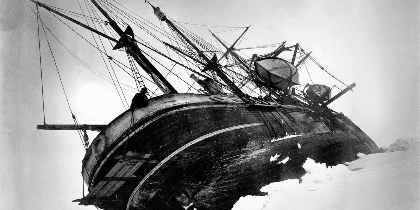
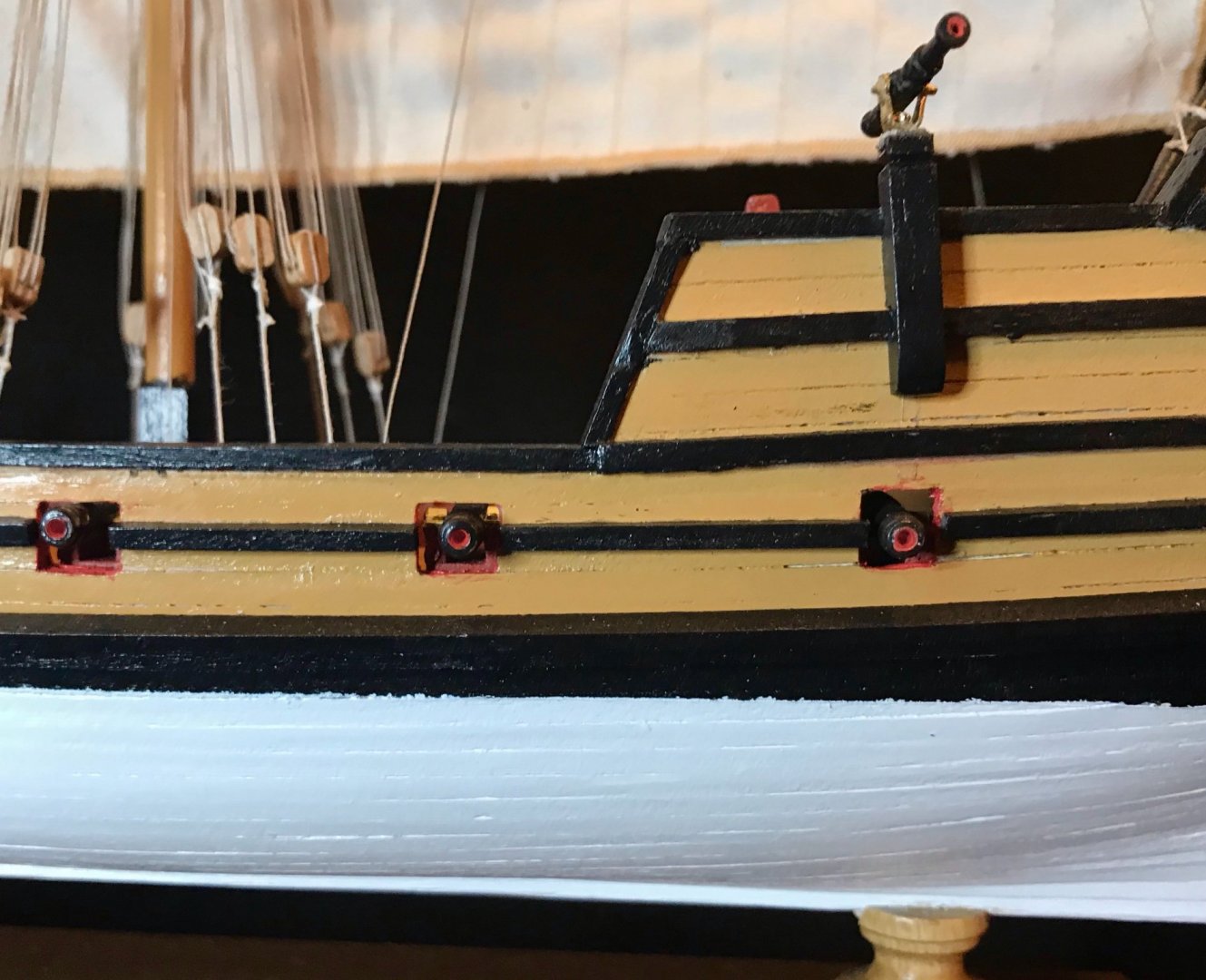
Hi Keith, Tom, and Johnny, and thanks for following along! Tom, I hope the build log will be helpful. At the very least, I'm sure you'll learn from my mistakes. Johnny, that's a wealth of information that I'll need some time to digest! Thanks for all of this! Given my current skill level, some of what you are describing sounds like great advice for builders who are better than me. (My plan is to stay mostly out-of-the-box and to use the opportunity to develop my skills, though I love your suggestion to get the eyebolts in the deck before mounting the decks.) The two key differences I'm planning are to taper the planking—something I need practice with. I might use the approach OcCre recommends for the first planking, but the second, I'd rather go for the tapered look. The paint scheme also strikes me as really strange. It's clear from Frank Hurley's photos that the ship was painted black above the waterline, but not below. For example: In one of the color photos, this seems to be antifouling "brown stuff"—it's a dark rusty red color, at least. I'd share the photo, but I foolishly forgot to save it and now I'm having a hard time finding it again. My plan for right now is to use red ochre paint below the waterline.
-
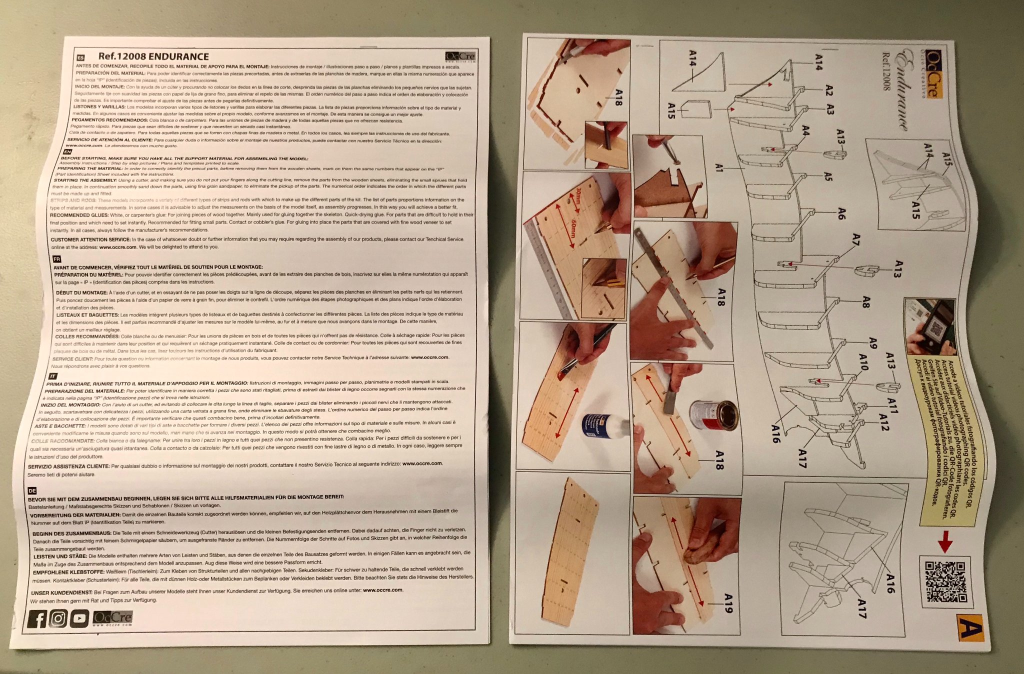
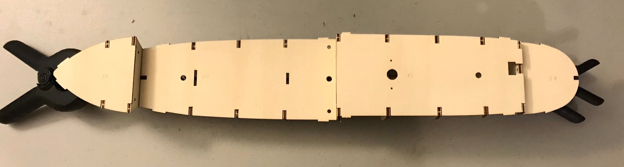
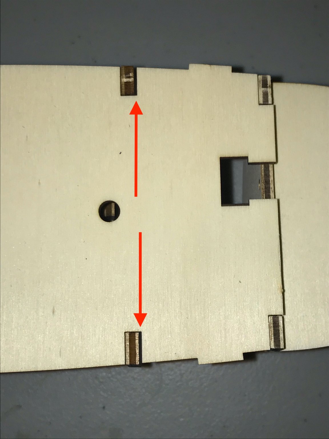
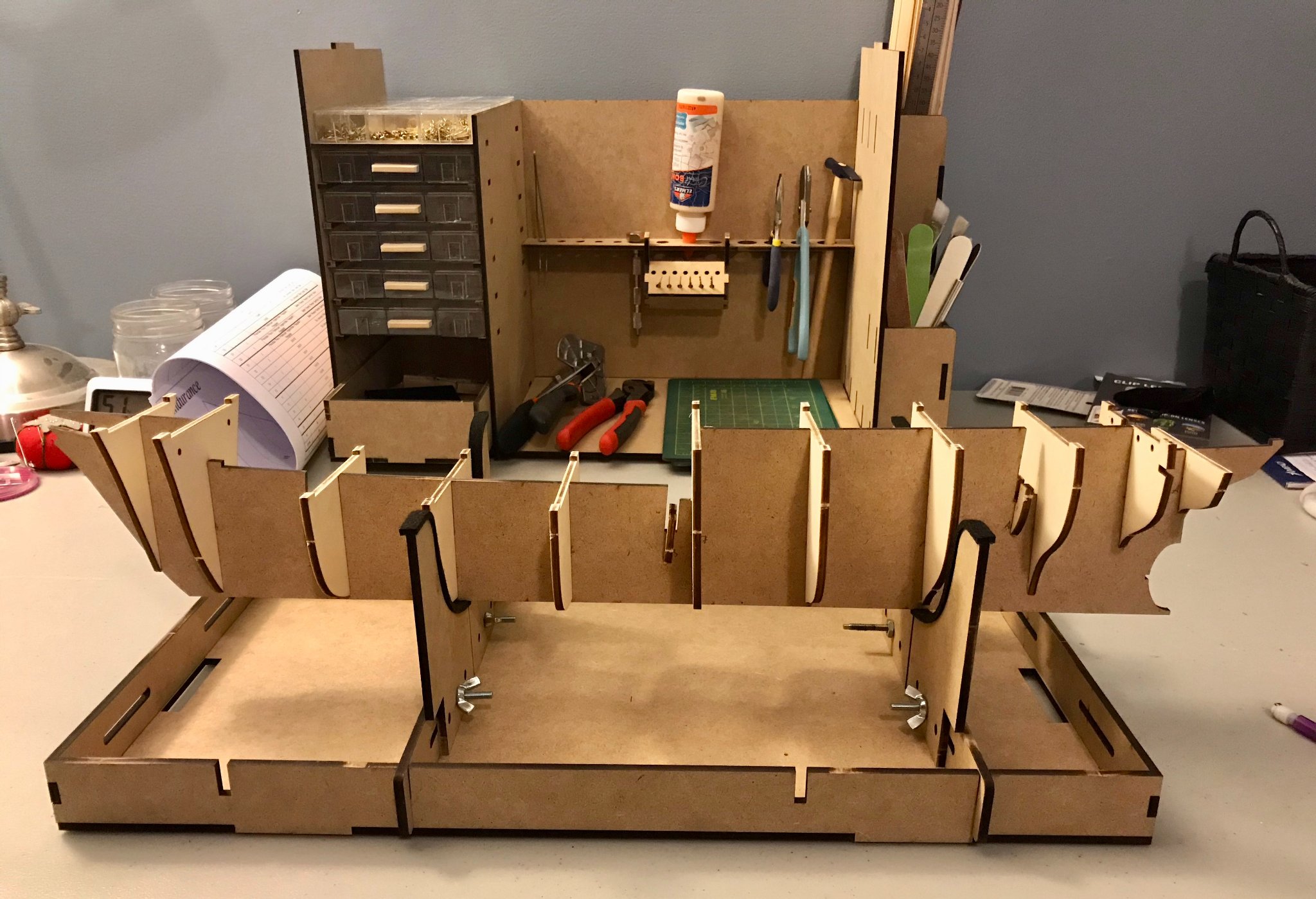
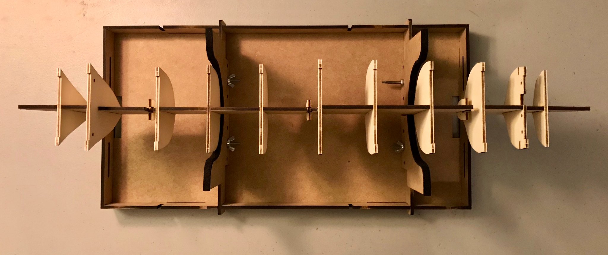
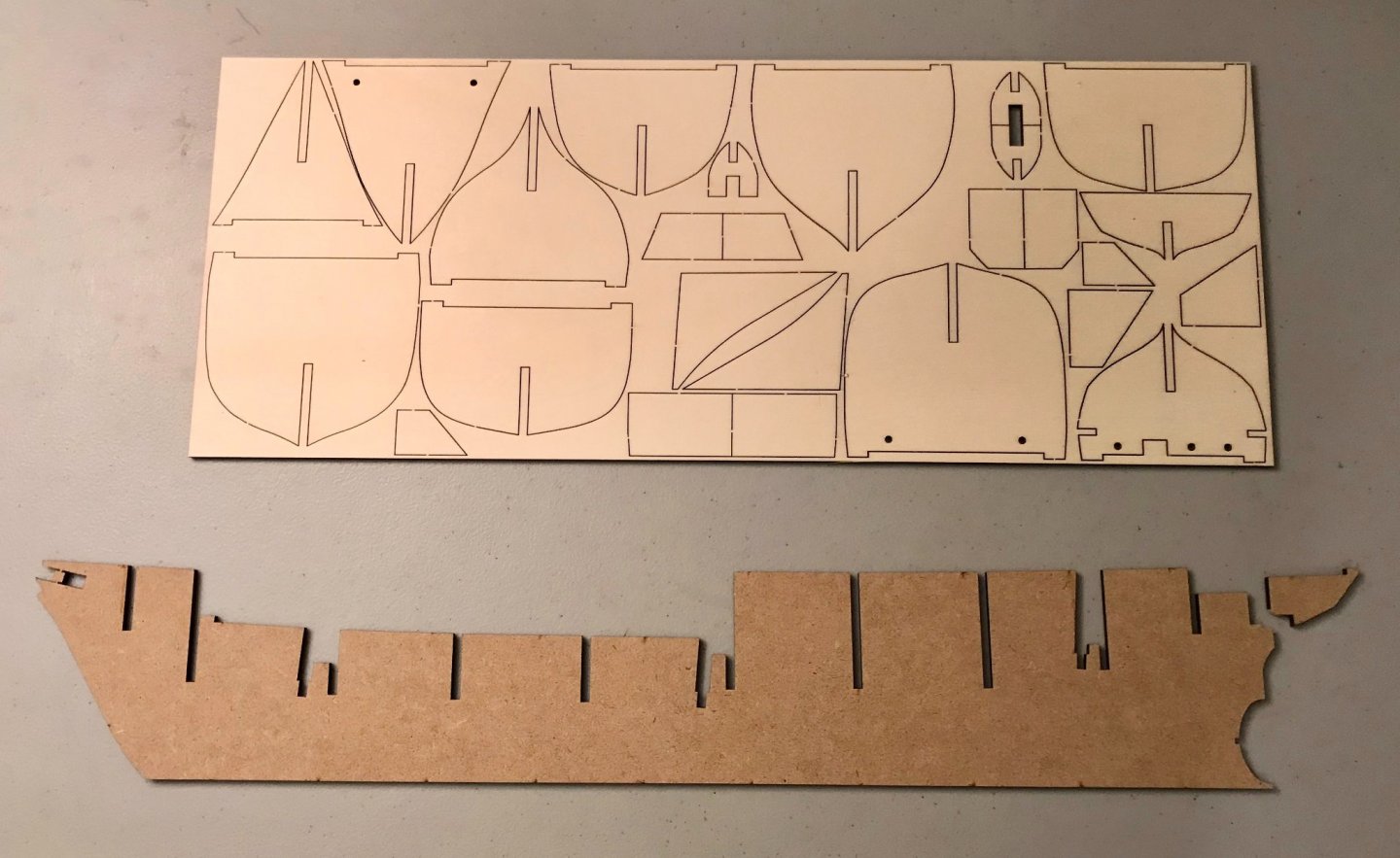
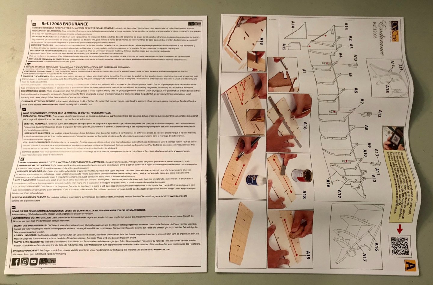
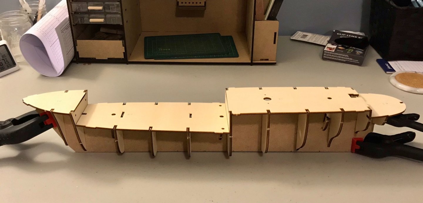
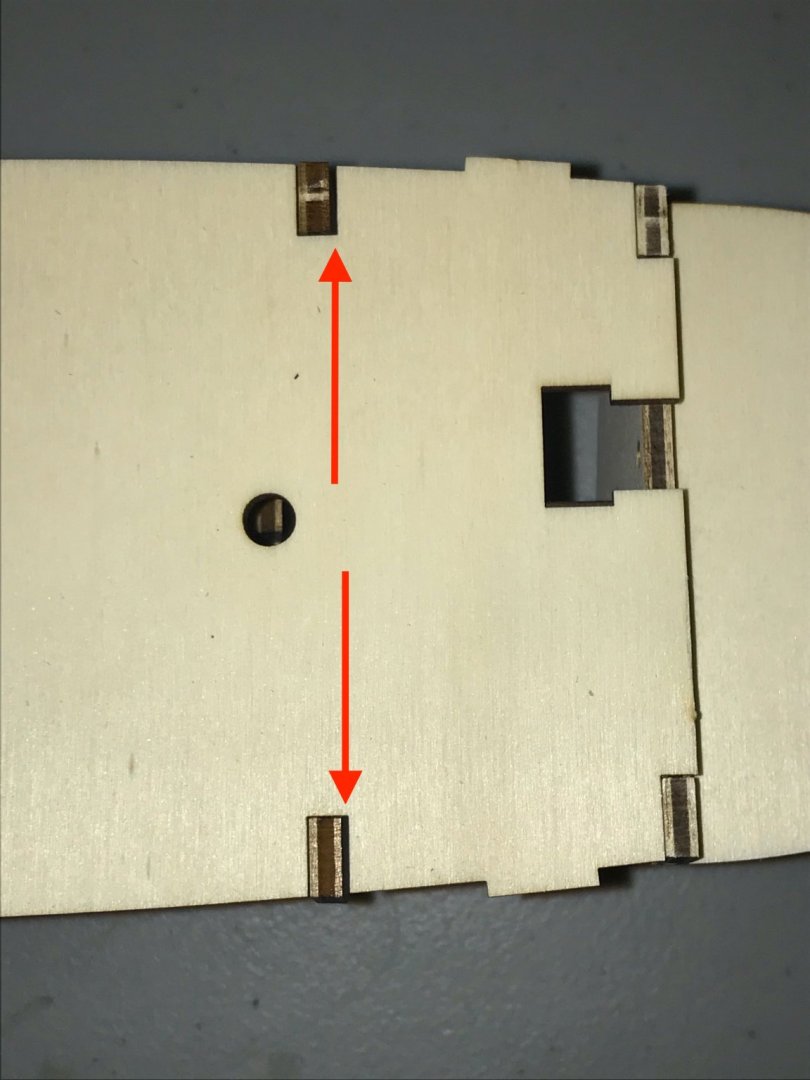
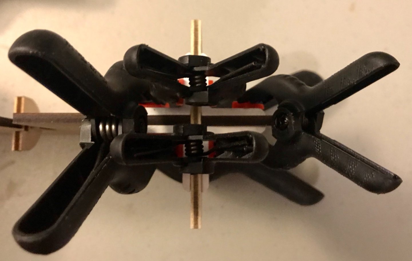
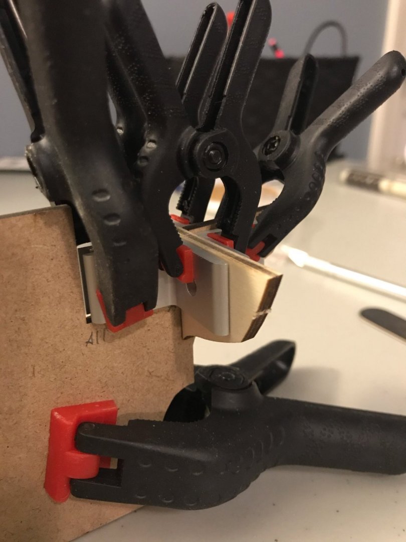
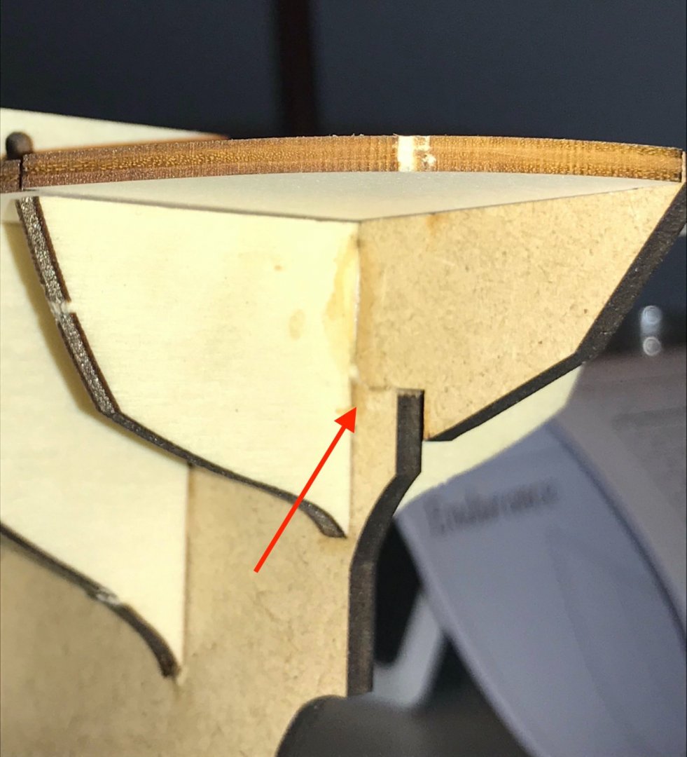
If you've read my last build log, then you know I had a list of six ships that I was trying to decide between for my next project. You'll also know that the Endurance wasn't on that list. But, well, that's the way it goes sometimes. A little more birthday money rolled in than expected, along with some money from an Easter gig, and suddenly I had a bigger budget to consider. Then I discovered that OcCre had released the Endurance and that, even better, Ages of Sail had it on sale! And so here we are. The story of the Endurance is, of course, well known on this forum, so I don't see any need to rehash it here. But my story with the Endurance isn't. I've been fascinated by Shackleton's journey ever since high school, when I was fortunate to perform Tim Mahr's tone poem Endurance at All-State Band. (Here's a recording if you haven't heard the piece before.) While learning my part, I read Alfred Lansing's book and was hooked. Since ordering the kit, I've been re-reading Lansing's book, watching documentaries, and so on. I've been carefully poring over Frank Hurley's photos from the expedition (especially his color photos!). I've also been studiously watching the tutorial videos posted by OcCre, which are still being posted as I write this. Before deciding to purchase the kit, I also carefully read Chris Coyle's very helpful review of it. He writes near the end that "I believe this kit can be built by an intermediate builder, and it will undoubtedly produce a nice-looking model right out of the box." I hope I'll be proof of that, though I'm probably closer to an advanced beginner than an intermediate builder And now, on to what you're waiting for—lots of photos! Chris is a better judge than I am of the materials and he's also a better photographer, so I'll just refer you to his review to see the materials laid out. But to my eye things are generally pretty good, with two exceptions. First, there's a packaging issue. All of the plywood sheets and the false keel (made of MDF) come in a plastic-wrapped flatpack. But the false keel is clearly able to move around a bit, which puts it at risk for damage. The portion of it that extends behind the rudder broke off and even escaped from the plastic! Second, one of the sapele planks was broken (shown in the photo after I removed the rubber band around it). I don't think this will be a supply issue, but it was a little disappointing to see. Apart from those two issues, though, I'm pleased with what I'm looking at. The hardware, blocks, and deadeyes look much better than some of the other kits I've done. The instructions are only one page in each language, but it's a B3-sized page, so there's enough there to be of some help. The book of step-by-step color photos is also on B3 paper, so OcCre can really pack in a lot of detail. Coupled with their tutorial videos, it's entirely possible that I'm over-confident at this point, since they've made things so accessible. The only weak part of the instructions is that the paint guide lists recommended paint colors for all OcCre models...except the Endurance. The updated sheet is on their website, but hasn't made it into the boxes yet. And now, onto the ship itself. Today, my goal was to get the frames onto the false keel. After numbering the pieces and cutting them out, I dry fit the frames and decks. The laser is used a bit generously on some pieces, but the measurements are spot on. Everything slid right into place and fit as expected. The only exception is that there is a little extra space (.5mm or so) on the 9th frame; the red arrows in the third photo here are indicating those gaps. (The 10th frame is in backwards in that photo, so the companionway is blocked...oops!) After checking the fit I was ready to start gluing in the frames. I used corner brackets to make sure everything was square. Since I didn't have enough brackets for all the frames I worked in shifts, alternating frames. Frame #11 (piece A12) needed some extra attention, since I also had to repair the broken piece of the false keel. After a few failed attempts, I ended up securing the false keel, frame #11, and the broken piece using four corner brackets and four clamps. Although the scar looks a bit dramatic in this close-up, it feels smooth to the touch and the poopdeck fits perfectly at its various contact points. By the time I plank the stern, this will be heavily reinforced, so I'm not terribly worried. After the first work session, here are the false keel and frames. This was my first time using the corner brackets (a tip I'd picked up here on MSW), and I'm really pleased with how square and symmetrical everything is. There's a long ways to go, but I feel good about this first step.


-
Thanks, Bob! I didn't know anything about xebecs before getting this kit, but I have really come to love the lines of the hull. That long, sleek shape really makes my other ships look short and squat! As for my next kit...I'm starting to narrow things down. It'll probably be selected from La Rose by Panart, Le Cerf by Mantua, Marie Jeanne either by Billings or Artesania Latina, Le Renard by Artesania Latina, Sloup by Corel, or the Toulonnaise by Corel. I have a birthday coming up so one of these will be a gift to myself.
- 79 replies
-
- 1
-

-
- sergal
- sciabecco francese
- (and 1 more)
-
Thanks, Clare! Each ship in the flotilla has its flaws, but it's gratifying to be able to look at them together and see the progression of my skills and knowledge. Now I just have to figure out what to do next! It'll be another French ship...but I have several on my wishlist and I haven't made a decision yet.
-
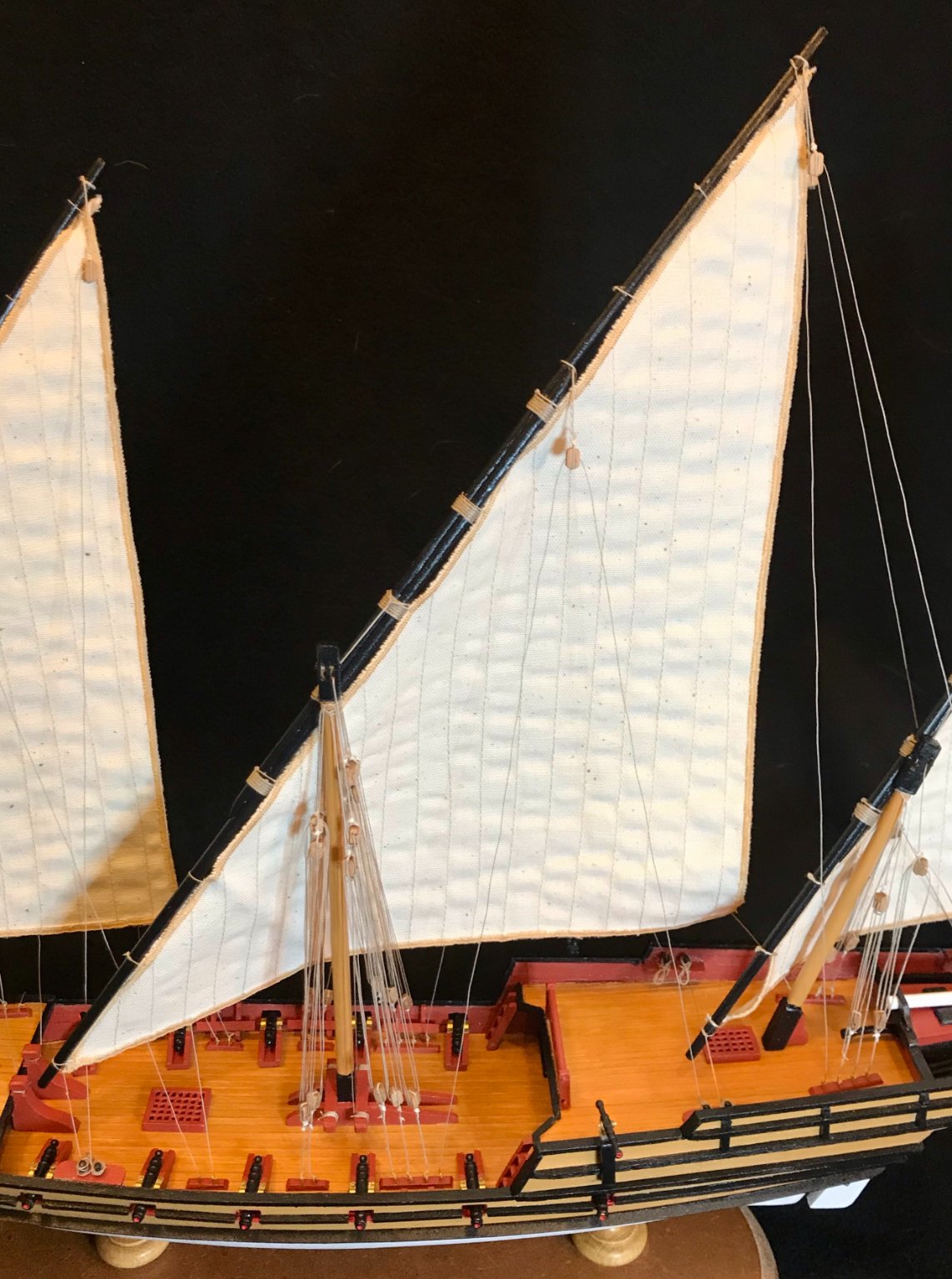
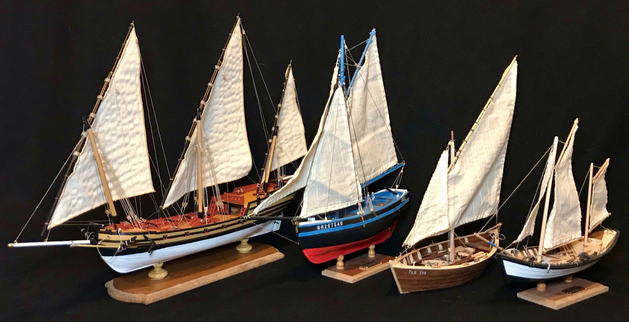
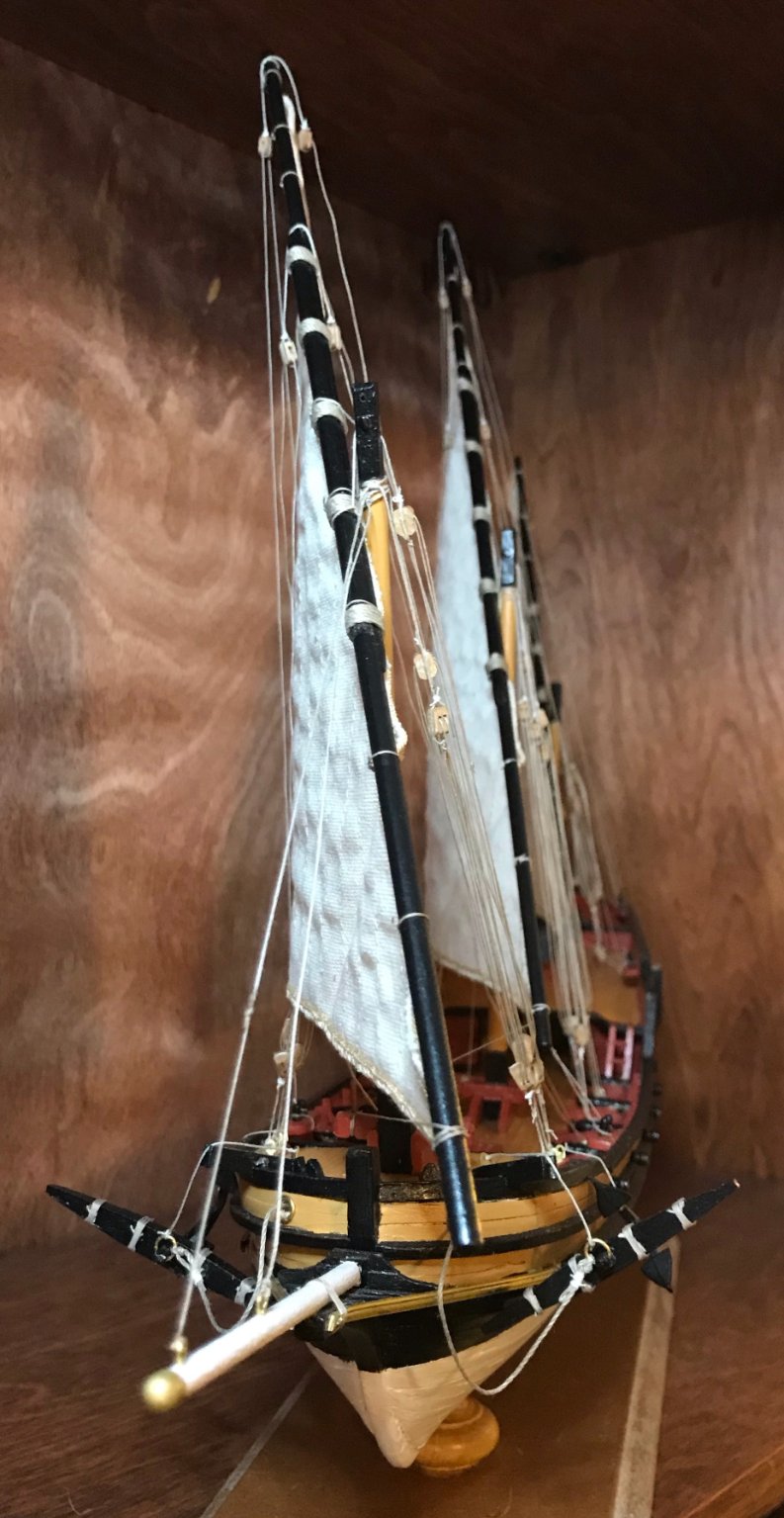
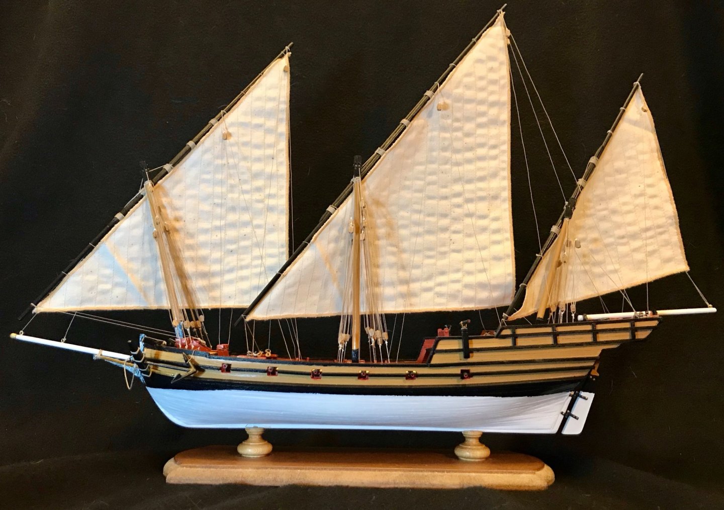
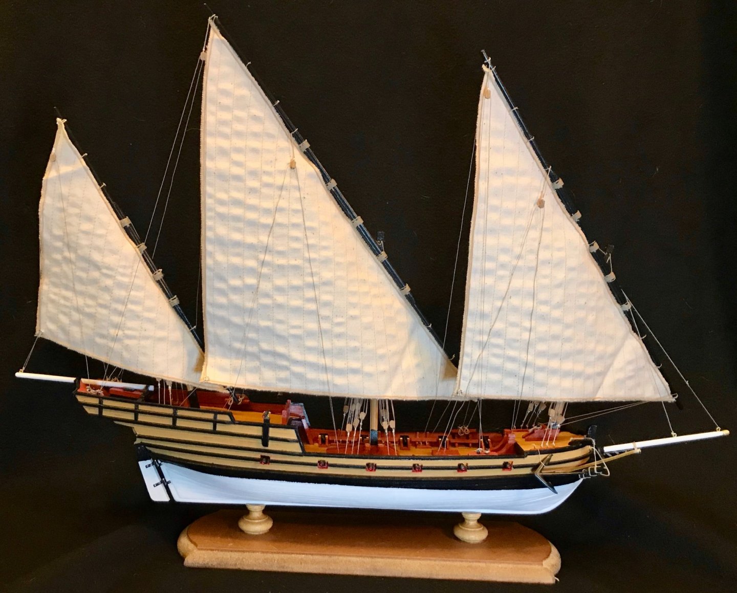
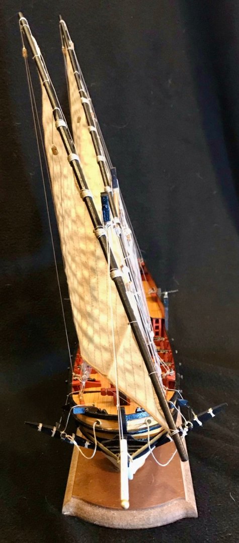
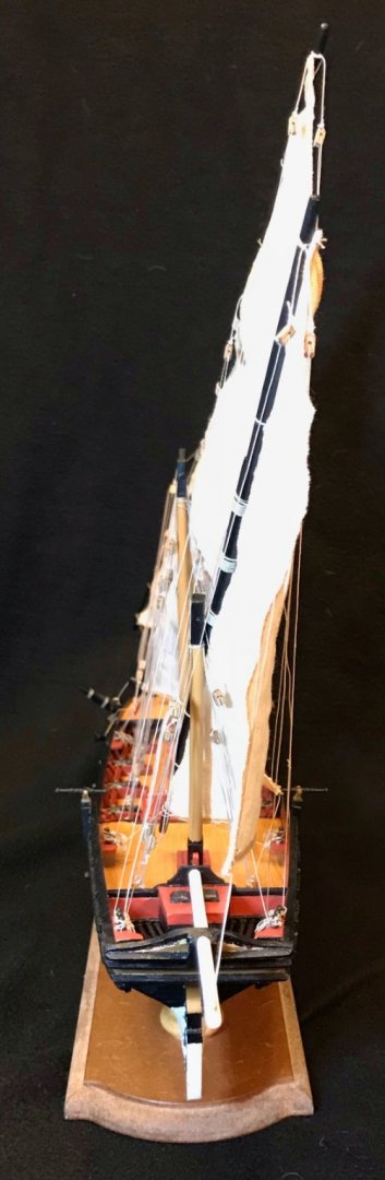
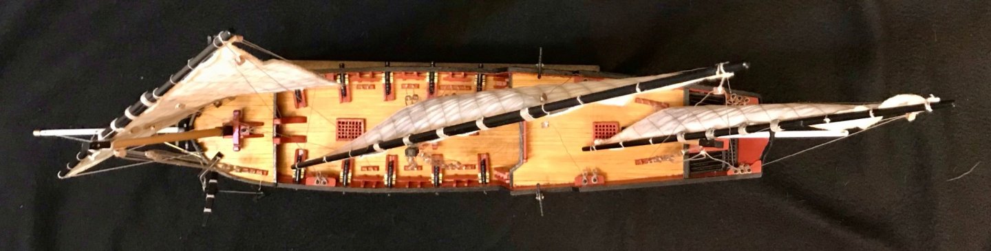
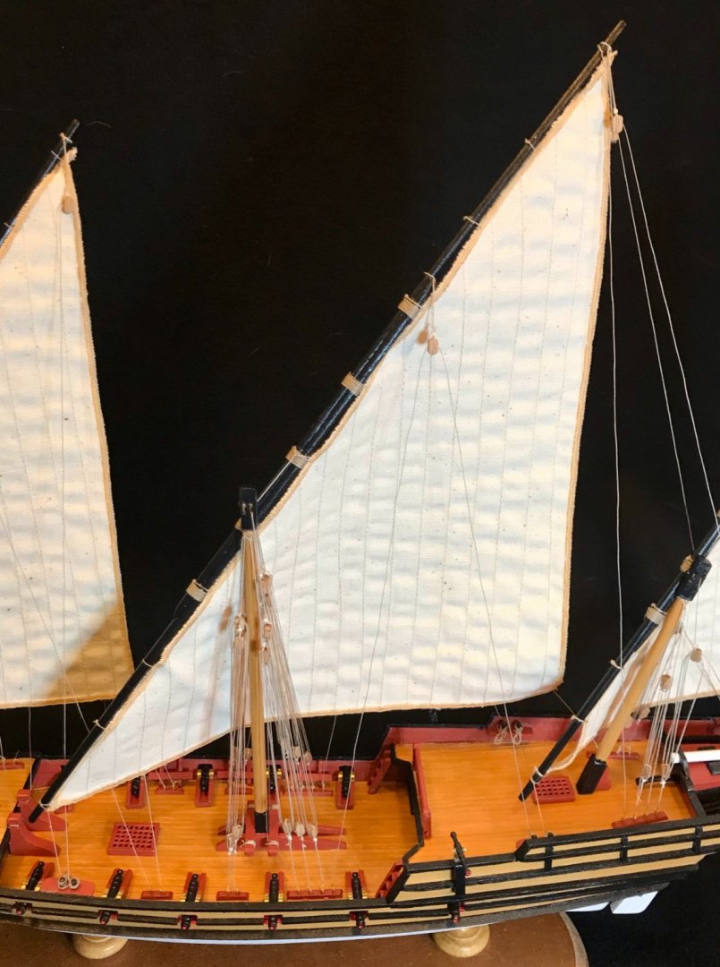
Glamour shots! Thanks to all who've followed along. Thanks especially to you, Bob, for the supportive comments throughout. This project was a big step up from my previous projects. There were definitely some doubts and mistakes along the way, but I'm really pleased with how it turned out! First, some full views of the xebec, starting with the port side: Starboard side: Bow and stern: Overhead: And details of the hull and deck fittings. First, the foredeck and bowsprit from starboard bow: The foredeck from the opposite angle: The main deck, looking forward: The hull amidships, showing cannon and a swivel gun: The aftdeck and rudder well: Portside view of the stern and rudder: And a few shots of the rigging. First the full rigging of the foremast and sail: A full shot of the main mast and sail: And the mizzenmast and sail: Finally, a couple close-ups of the mainmast, showing the rigging of the masthead, antenne, stays, and halyards: I started making model ships as stress relief during the pandemic. So, as we pass the anniversary of the lockdowns here, it seems appropriate to wrap up this project with a shot of the flotilla I've built in the past year. While the three fishing boats each took about 4-5 weeks, this xebec was a seven-month project that kept me occupied through fall and winter—I unboxed it on August 31 and added the finishing touches on March 18. Here's my pandemic flotilla (order of completion, from left to right: 4th, 1st, 2nd, 3rd): Thanks for coming along on this ride!


- 79 replies
-
- 6
-
-
- sergal
- sciabecco francese
- (and 1 more)
-
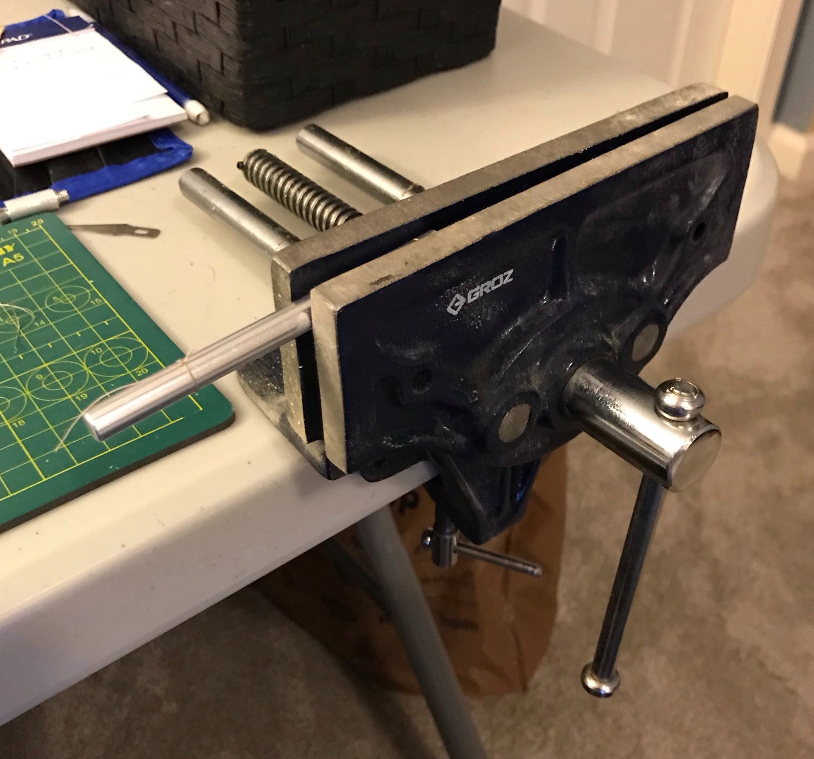
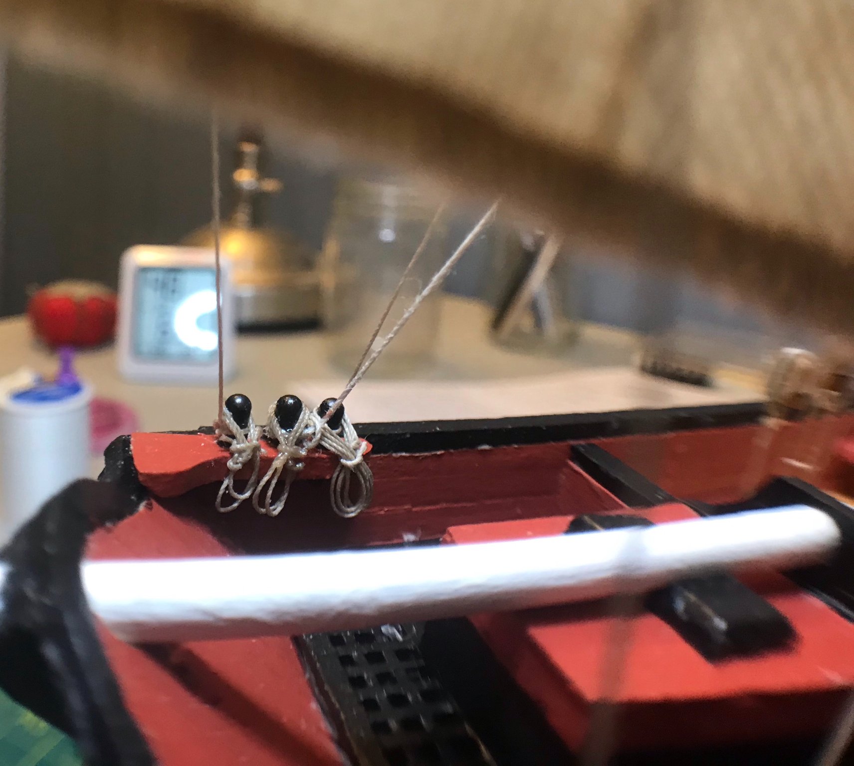
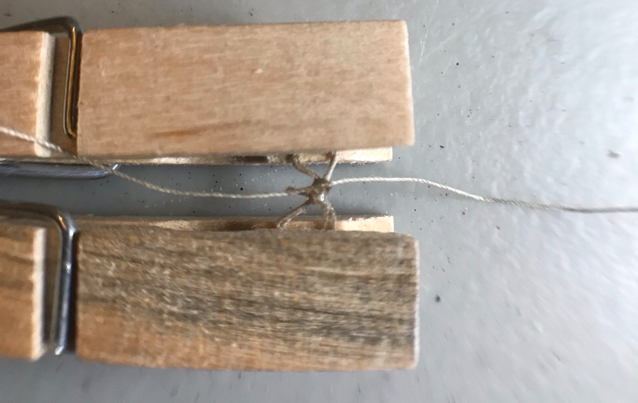
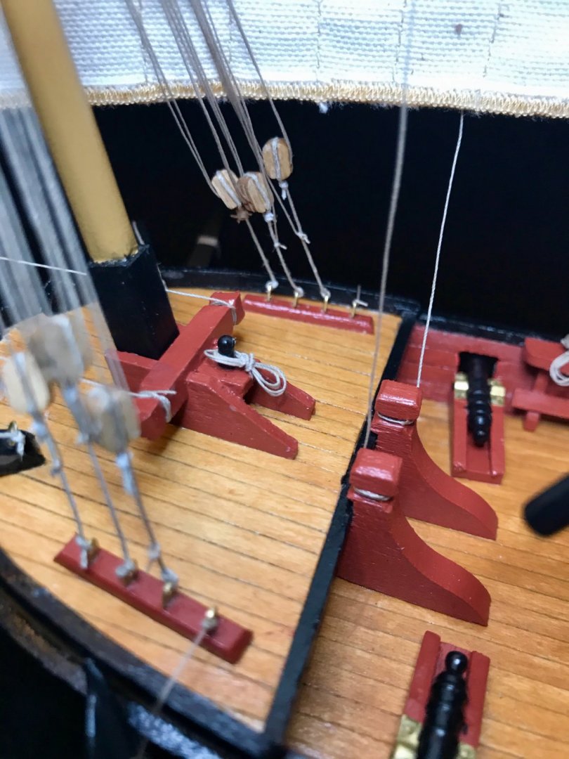
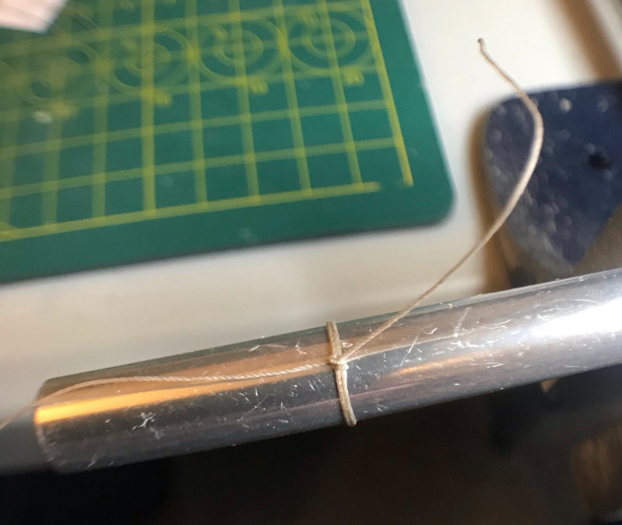
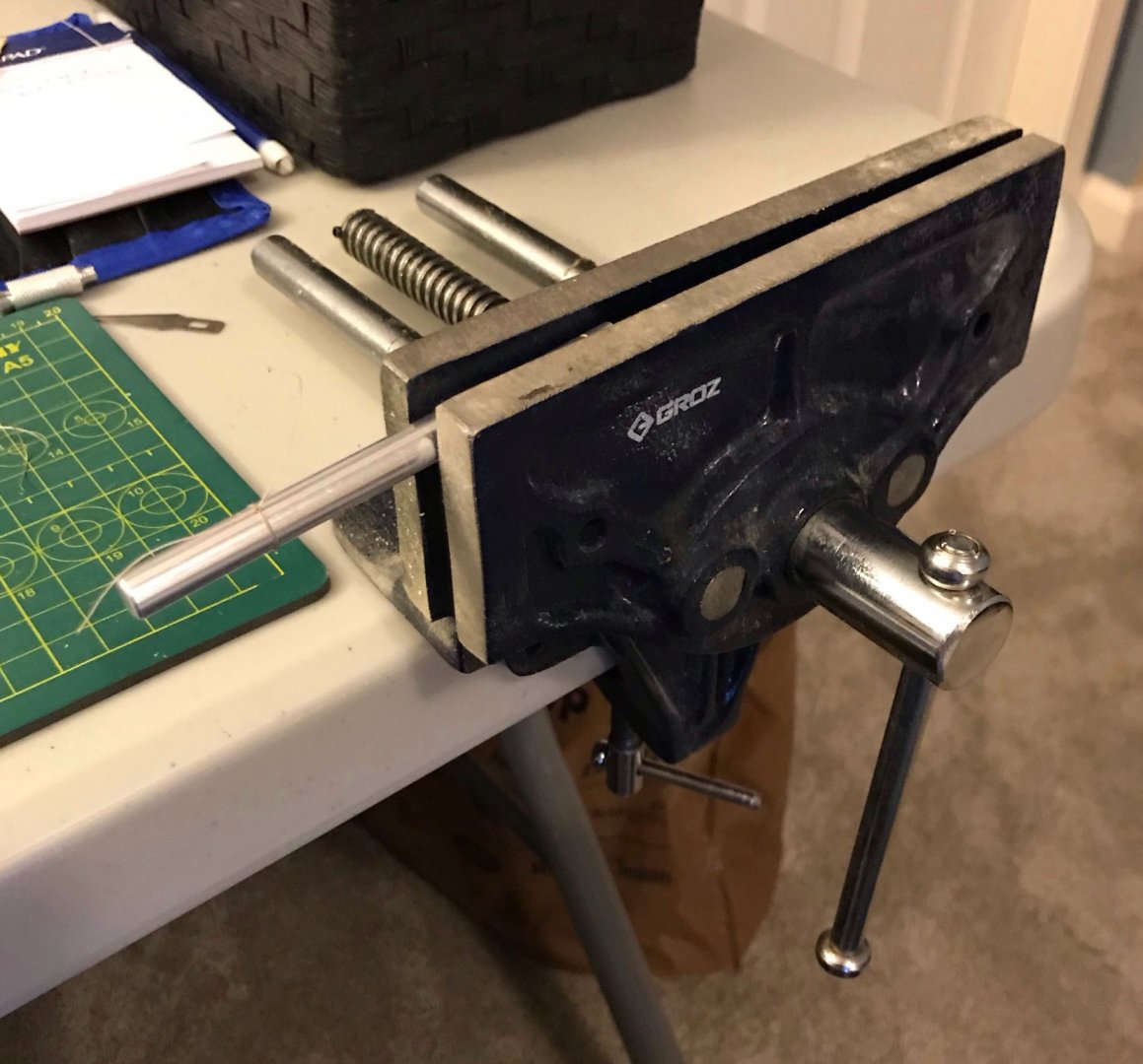
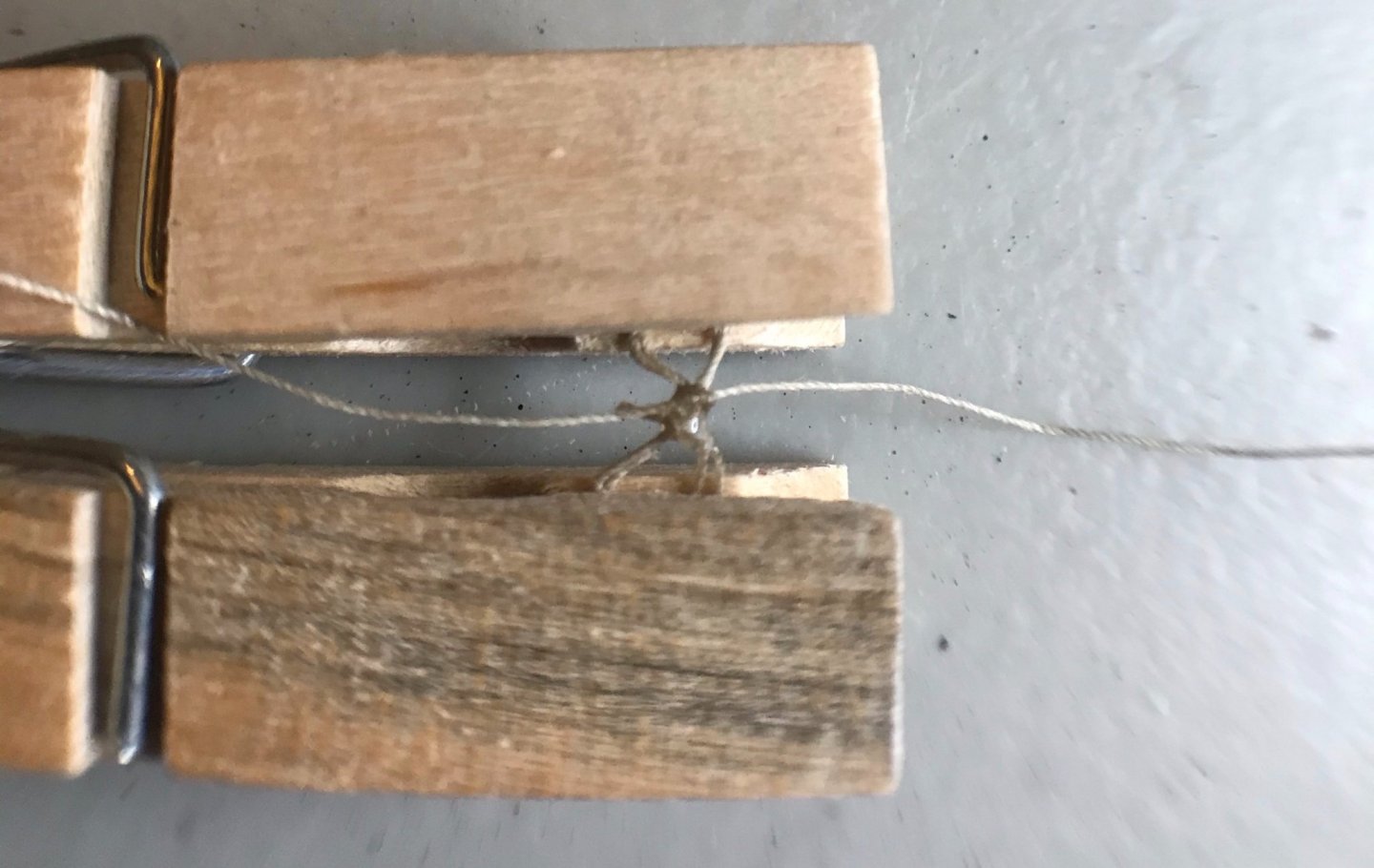
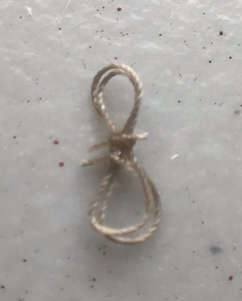
On to the last step—adding rope hanks to the belaying pins. This has not been easy. I haven't done it well on my previous kits, so I'm trying to figure out a method that works for me. After trying and failing on my own, I poked around on MSW and YouTube. I checked out Tom Lauria's method and then tried Peter Burton's method. I just couldn't manage to do them cleanly—though I highly recommend checking out their methods, especially if you're a more skilled than I am. In the end, I pulled Frank Mastini's Ship Modeling Simplified and finally made some with which I was satisfied. It's not as quick as Lauria's and Burton's methods, but that's alright. I've got the time and I only need to do 15. Here's how I've adapted Mastini's method: 1. The key to Mastini's simplified method is placing the handle of an Exacto knife in a vise. I had to remove the collet and blade to ensure it would stay put. 2. Next, Mastini recommends doing a common whipping knot with 2 to 4 wraps around the Exacto knife handle. After tying the common whipping, it's finished off with an overhand knot and a bit of diluted glue (I used a dot of Fray Check). 3. After sliding the rope coil off the Exacto knife handle, Mastini's photos show another overhand knot tied around the waist of the coil. I was having a hard time doing this, so here's where I am departing from his method. I very carefully clip the ends of the coil between two clothes pins and give one a half spin. This makes the coil into a figure 8 and gives it a clear waist. Using two tweezers, I wrap a thread around the waist and tie an overhand knot. (I'm running a little short on thread, so I'm using some of the longer bits that I cut off while doing the rigging. Sometimes I'm able to do this overhand knot with the loose ends of the common whipping, sometimes I'm using a separate short thread.) 4. After removing the hank from the clothespins, I apply another drop of Fray Check and trim the loose ends. 5. Then it's time to attach the hank to a belaying pin. Here are the first three, on the portside stern pin rack. Of these three, two were done with two wraps and one with four wraps around the Exacto knife handle. The one with four wraps definitely looks the best, but they all look better than on my previous ships. Progress! Right now, I have 4 down and 11 to go.

- 79 replies
-
- 1
-
-
- sergal
- sciabecco francese
- (and 1 more)
-
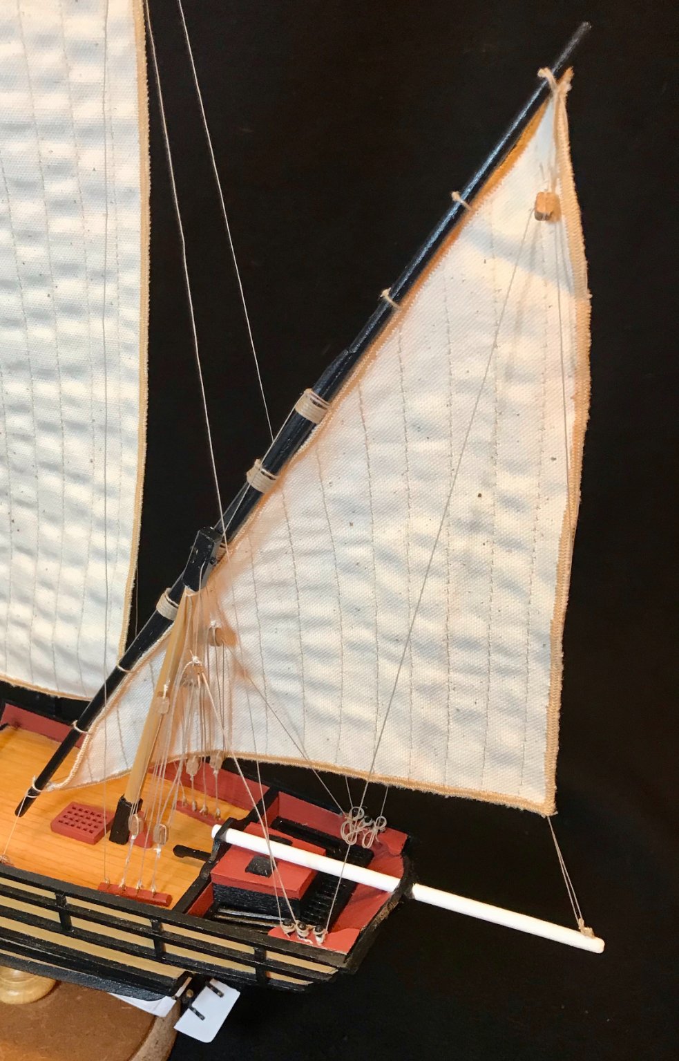
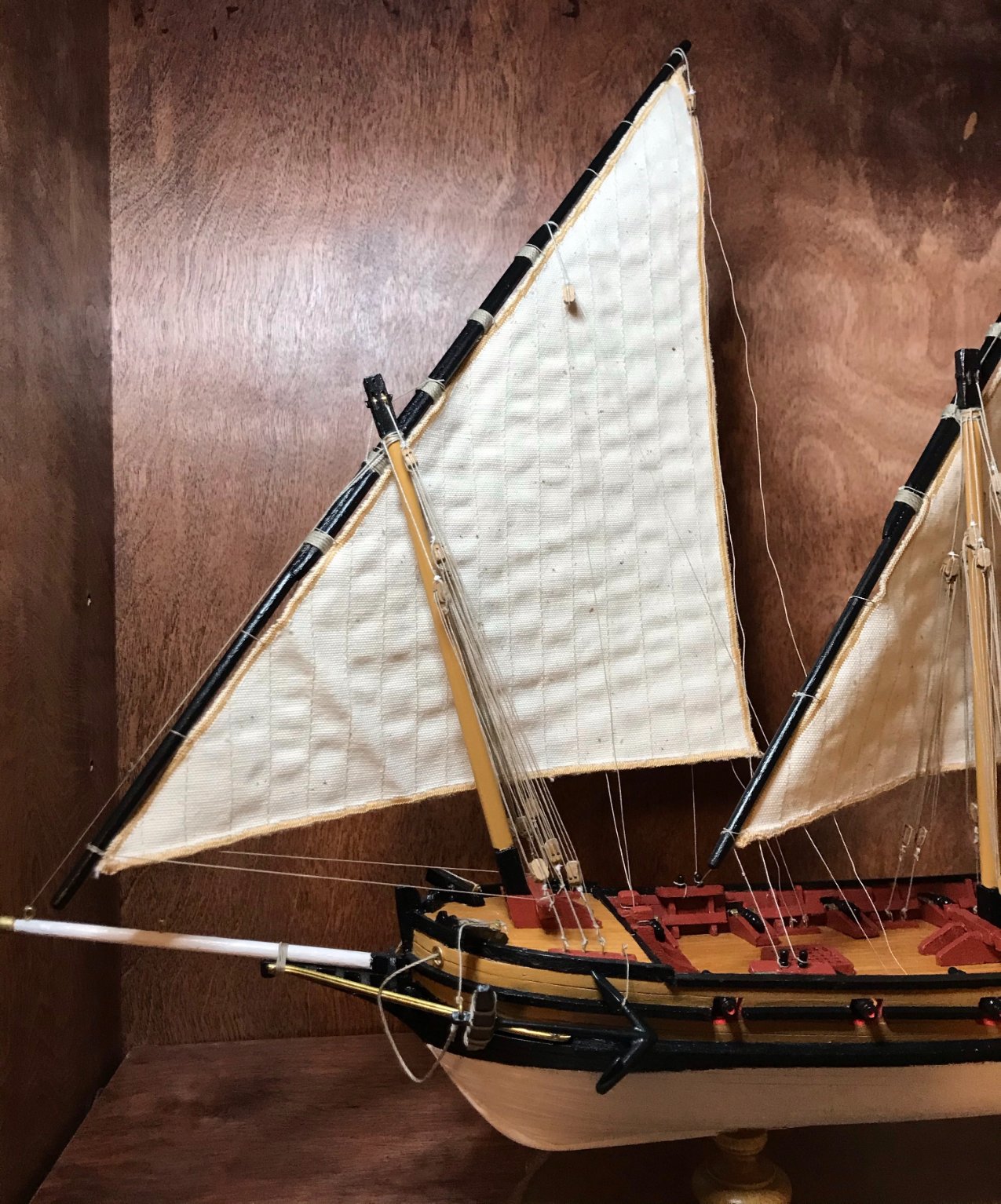
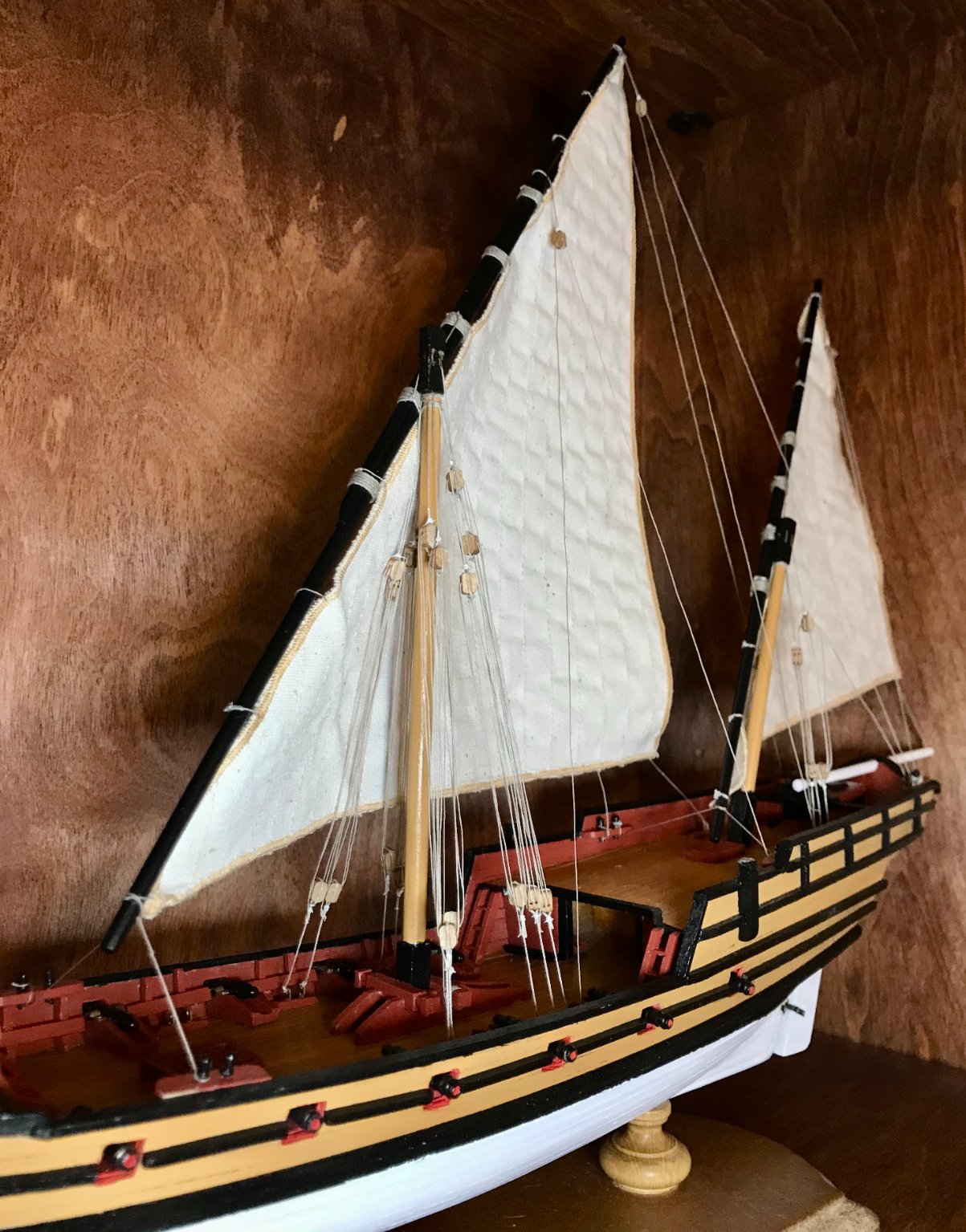
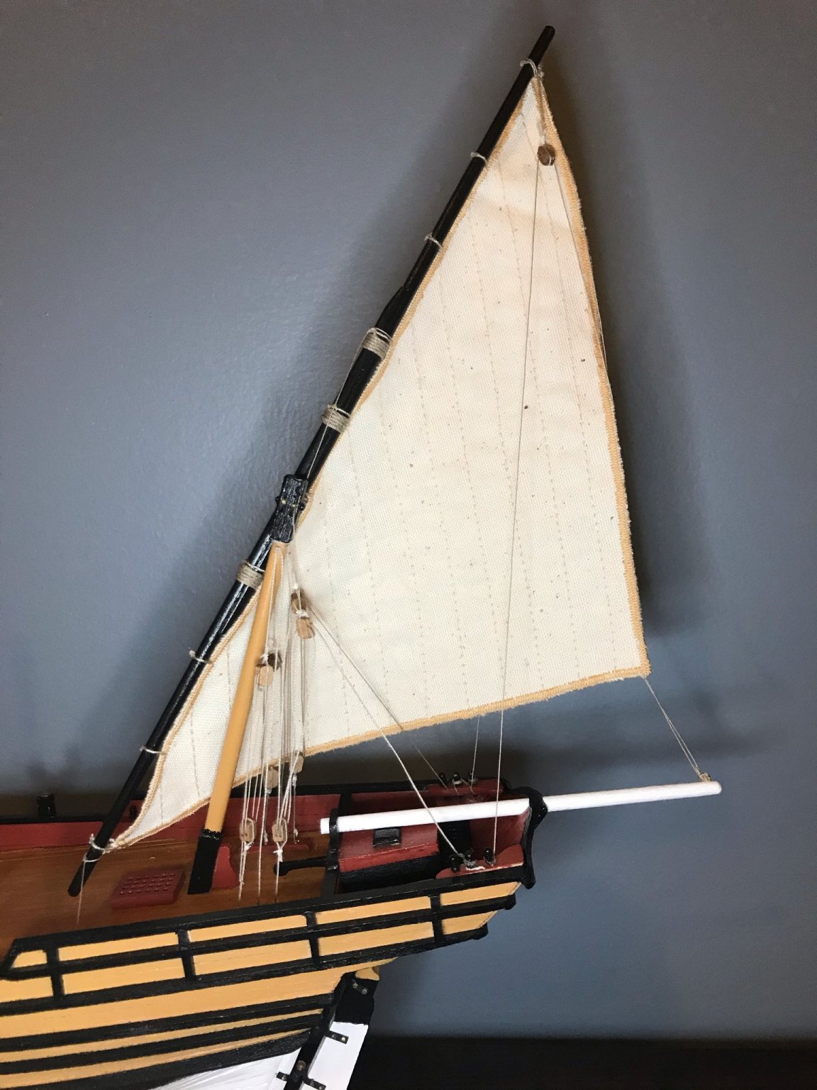
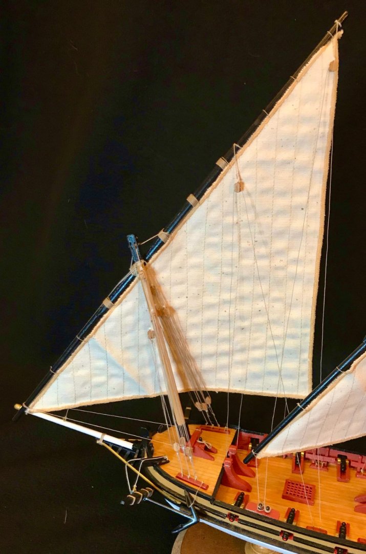
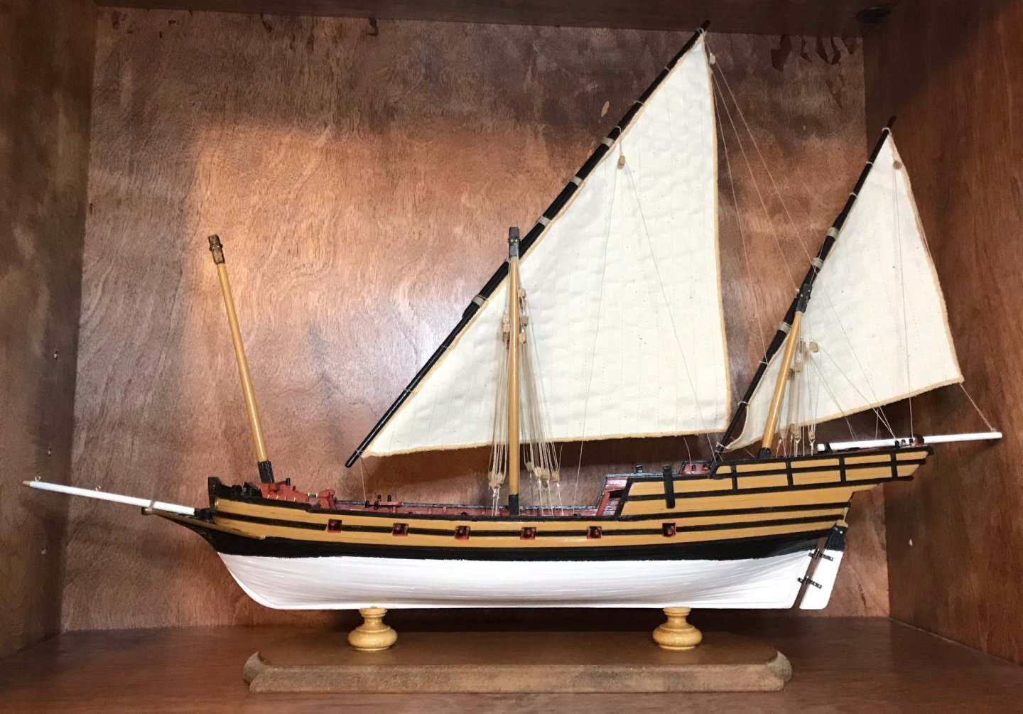
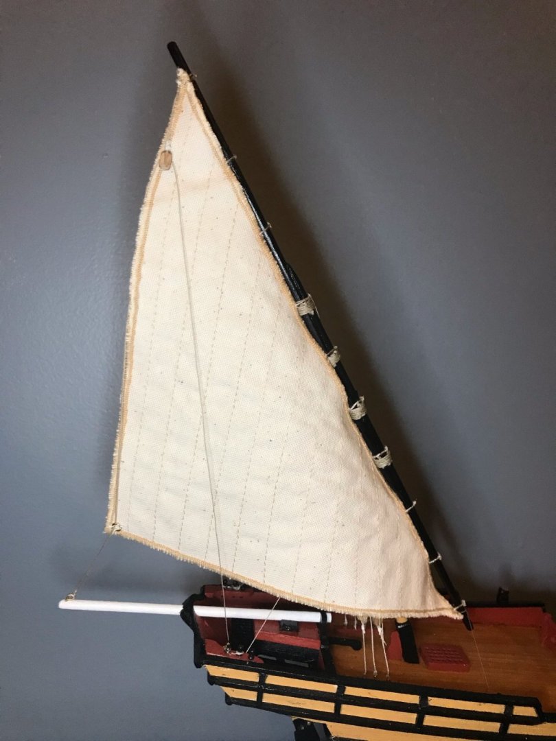
Thanks for the encouragement, Bob! Tonight I decided to just run with the momentum I've built up the last few days and hang the foresail! By this point, I've gotten into the routine of rigging these sails. The only new challenge was the overlapping rigging—going down each side, the attachment points on the main deck are for the fore garante, main ource, fore oste, fore garante, fore oste. I also need to revisit the portside oste, which seems to have too much slack on it. (That oste is clearly visible in the first photo, running from an eyebolt on the deck, to the block at the top of the antenne, then back down to a belaying pin.) But at this point, the rigging is done! You probably noticed that I removed the staysail. Well, once the foresail was up, it looked awful. You'll note in the first photo that the antenne and the luff of the sail (the hypotenuse of the triangle) line up perfectly with the forestay. As a result, the staysail wasn't visible from the port side; from the starboard side, it was at such a different angle from the other sails that it just didn't look right. So, off it went. Instead, I have the more classical look of the three lateen sails. Next steps: Finishing details, especially making rope hanks for the belaying pins and reinstalling the balustrade and swivel guns. The next set of photos should be the glamour shots!


- 79 replies
-
- 1
-
-
- sergal
- sciabecco francese
- (and 1 more)
-
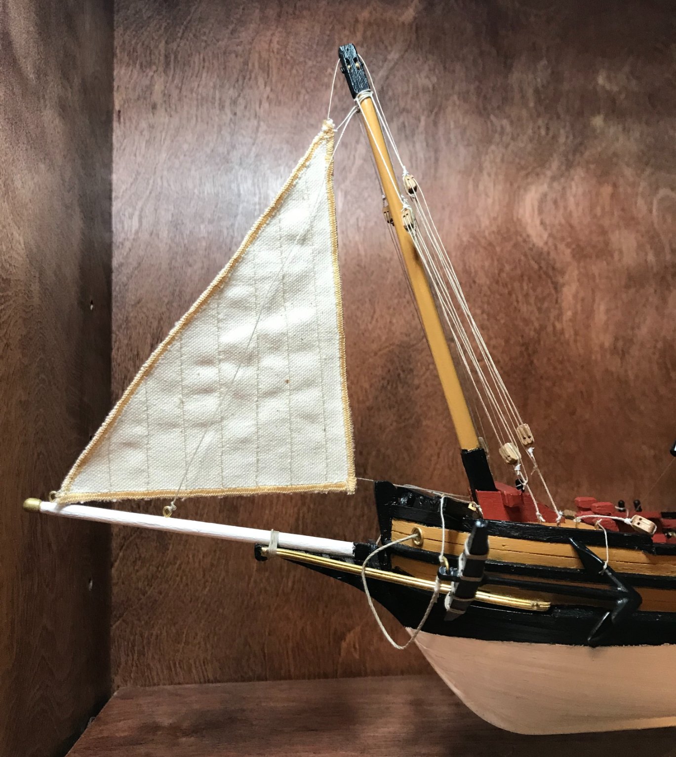
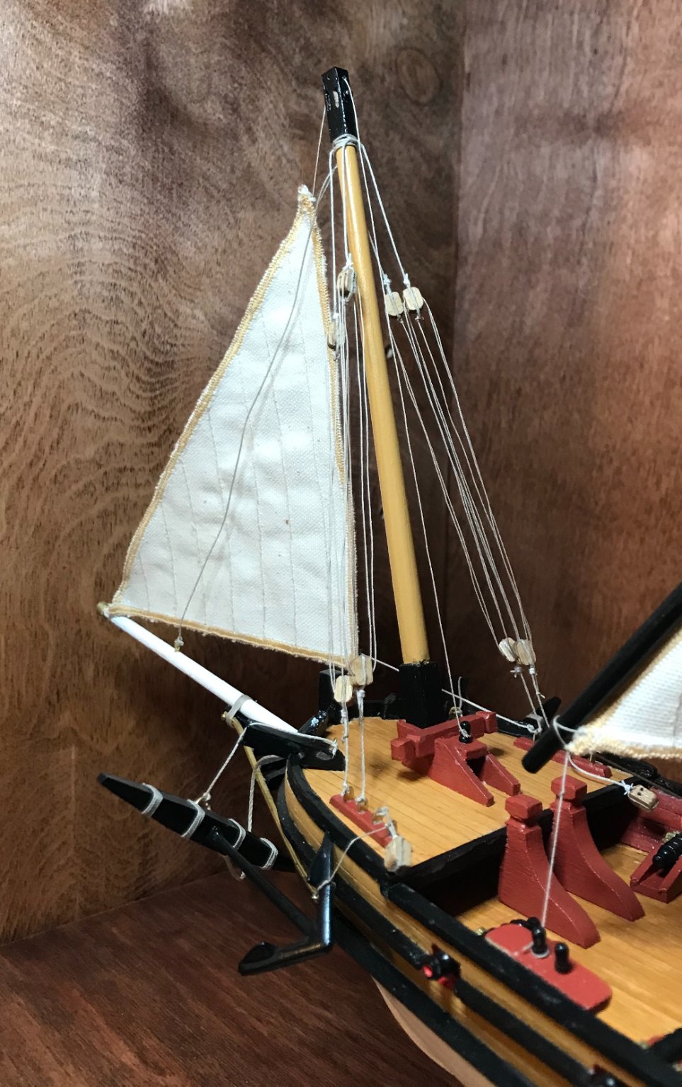
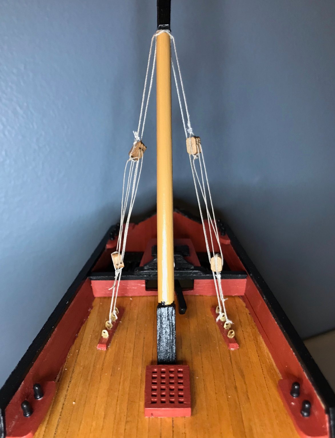
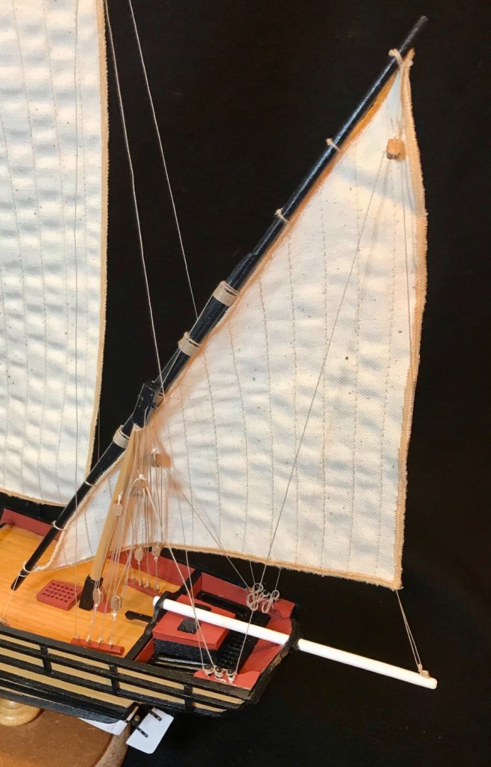
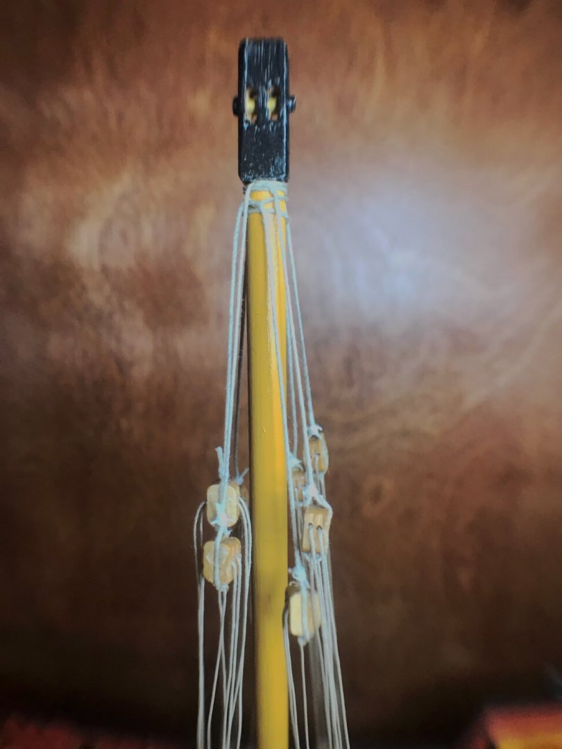
I really got on a roll this evening! Not only did I seize the blocks and sew rings onto the sails, but I also managed to rig the stays on the foremast. This included two stays running down to each strip of eyebolts on the foredeck, as well as two forestays running down to the bowsprit. In attaching that, I also needed to hoist the staysail. Some finicky work, but it went mostly pretty well. I would have preferred to put the staysail on the after forestay, but it didn't fit at that angle. Since the kit doesn't come with the sails, I had to find a solution for the staysail halyard. Although I had prepped for this when building the foremast assembly, now you can see it in place. It runs from the sail, through a .6mm hole drilled through the centerline of the masthead, and ties off on a belaying pin mounted between the foremast knees. Next steps: Attach the foresail to the antenne, then hang it. After that, there will just be a few details to work out—reinstalling the balustrade and swivel guns, and making rope hanks for the belaying pins. The end is approaching quickly!


- 79 replies
-
- 1
-
-
- sergal
- sciabecco francese
- (and 1 more)
-
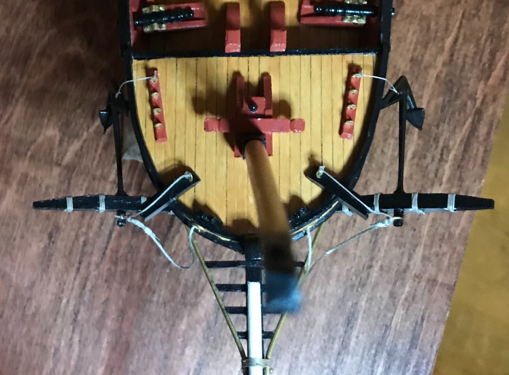
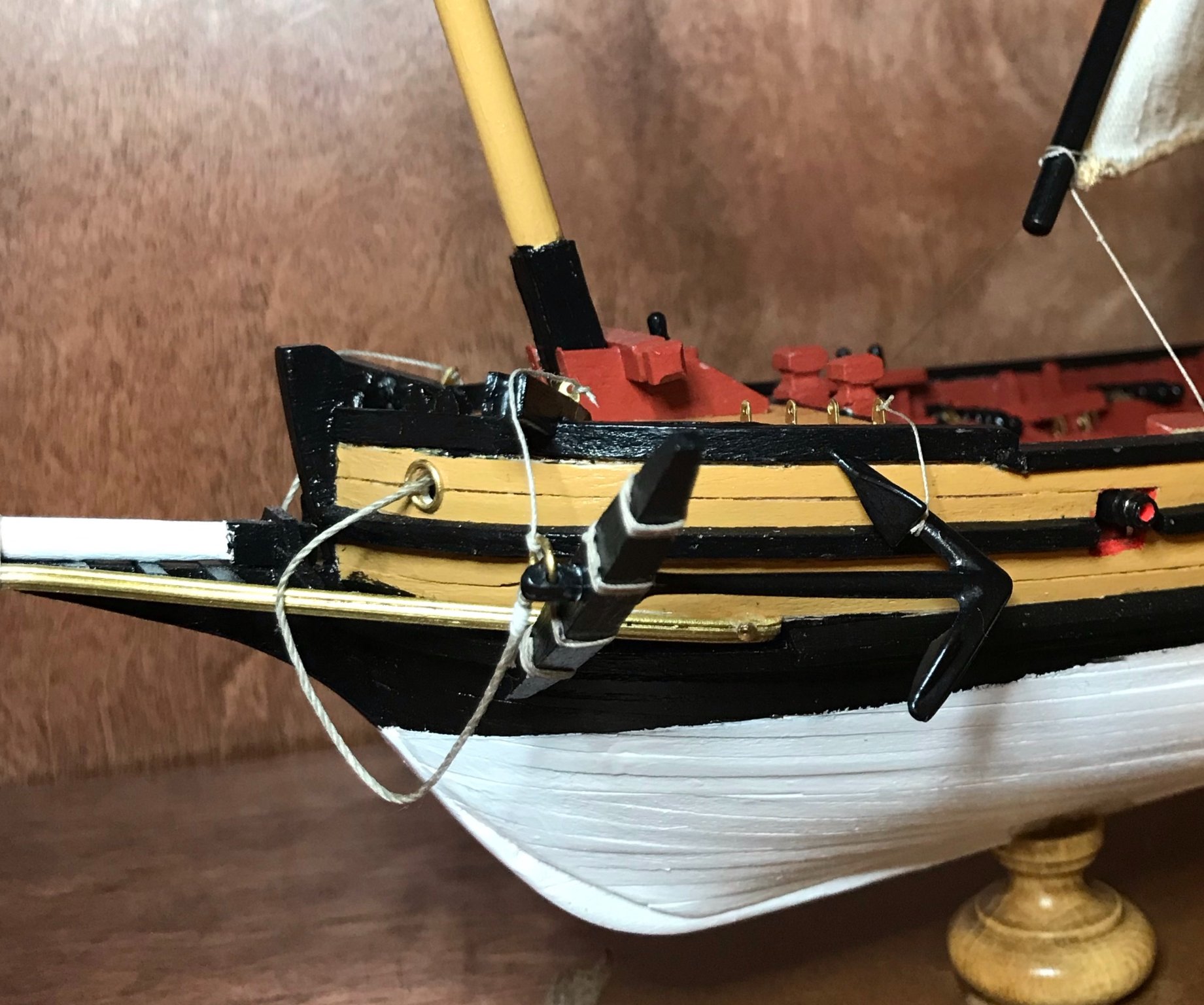
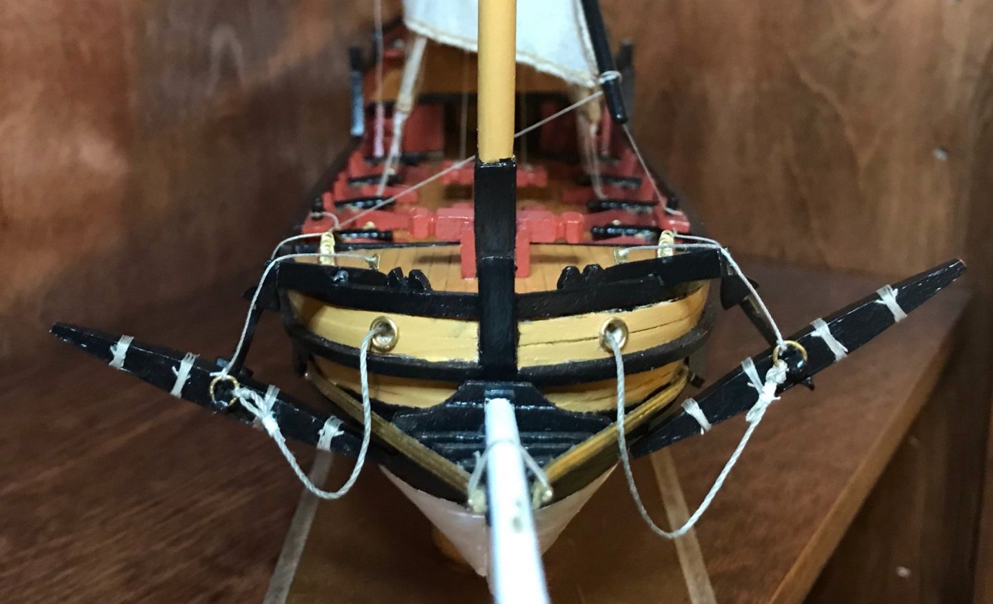
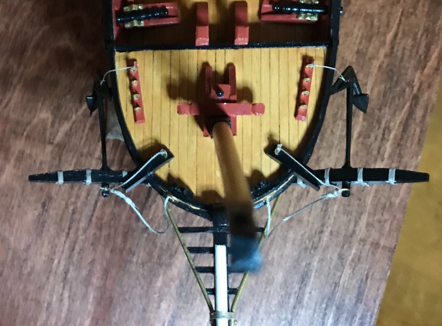
Tonight, I began preparing the blocks for the stays and rigging, gluing the thread on to the blocks. Next on that front will be seizing the ropes. In addition, as I began working through the logistics of rigging the foresail, I realized it would be easier to install the anchors first. The photos aren't that great, but you can get the idea at least. There are three ropes for each anchor. The heaviest cable (1mm thread) runs from the ring through the hawseholes. Another rope (.5mm) runs from the ring, over the cathead, to an eyebolt at the inboard end of the cathead; that eyebolt isn't in the plans for the ship, but I added it so that I didn't have multiple ropes fixed to a single bitt. Finally, there's a short painter line (.25mm) that attaches the upper arm of the anchor to an eyebolt. The end result isn't quite how I pictured it in my mind beforehand, but I think it works okay—at the very least, the anchors are securely stowed! Next steps: Seizing the blocks on the rigging for the foremast and foresail. Also, sewing rings onto the foresail and staysail.

- 79 replies
-
- 1
-
-
- sergal
- sciabecco francese
- (and 1 more)
-
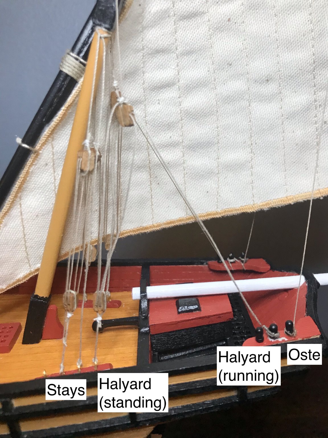
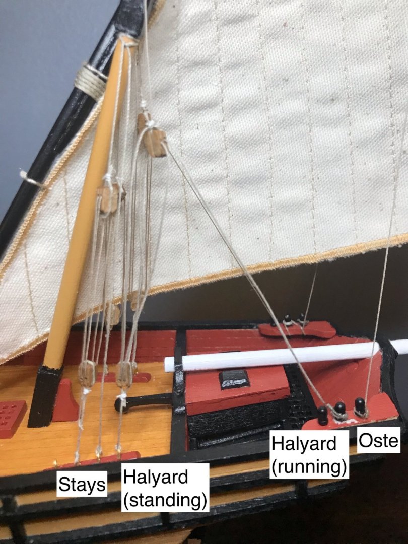
Continuing to work a step at a time right now, but I've just finished hanging the mainsail! In the process, I knocked the balustrade off again. So, I'm just going to set it off to the side with the swivel guns. I'll add those back on soon. The trickiest part is that there's so little room to maneuver. The halyards were a particular challenge since they are spaced 5mm from the aftmost stays. The overlap of the rigging also posed challenges with the ostes, the ropes that attach to the top of the antenne. The standing end of each oste attaches to the same strip of eyebolts as the mizzenmast stays, while the running end attaches to one of the stern belaying pins. However, I'm really pleased with how tonight's work looks—all of the blocks are hanging well, I managed to avoid crossing any ropes, and everything is satisfactorily taut. Next step: Prepare and attach the lower blocks for the foremast stays and foresail rigging.

- 79 replies
-
- 1
-
-
- sergal
- sciabecco francese
- (and 1 more)
-
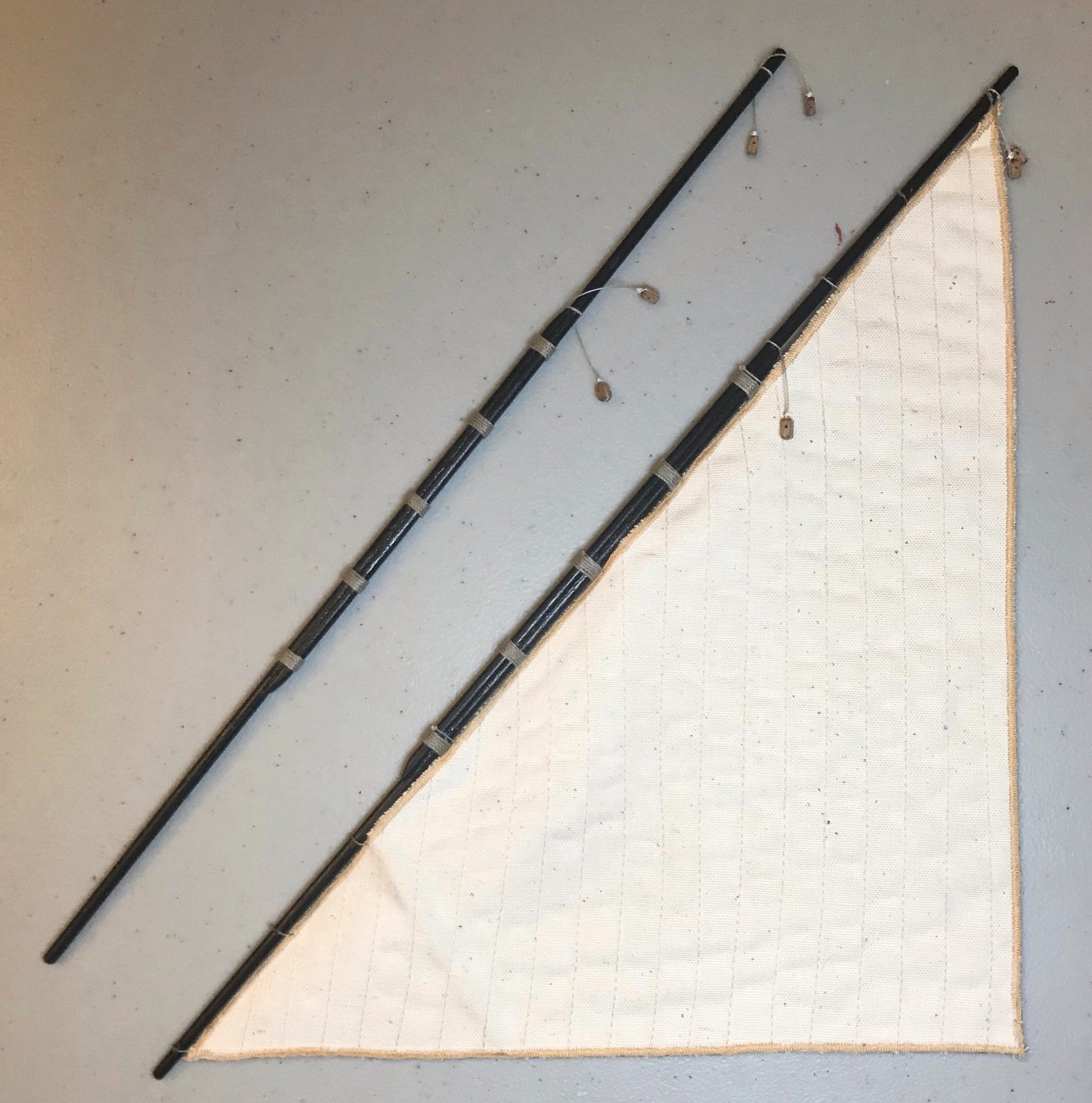
Thanks, Bob! Some good challenges here, but satisfying to see everything coming together. The end is in sight now! I managed to squeeze in an extra work session late this evening. After seizing a few more ropes, I added the pendants to the fore and main antennes, then tied the mainsail on to its antenne. An excessively large photo to show some of the details. (For reference, the fore antenne is about 33cm long and the main is about 37cm.) I posted before about the wooldings, so won't say anything further here. The garante and oste pendants are each a single piece of thread, with single-sheave blocks attached to each end. They're attached with an overhand knot and some Dritz Fray Check to glue them in place (you san see that best on the fore antenne on the left). The garantes and ostes themselves are long ropes with a standing end fixed to an eyebolt and a running end belayed to a pin; one of each on either side of the sail. I've also sewn a ring into the clew, though that's on the other side of the sail; the running ends of the ostes will pass through that ring on the way to the belaying pins. Next, I tied on the mainsail with eleven short pieces of .15mm thread. The middle five line up against the wooldings; then three going out to each end. Nothing fancy here, just a square knot and a few drops of Fray Check to glue them in place. Next step: hang the mainsail. I'll need to rig both halyards, add the ources to the bottom of the antenne, then rig the garantes and ostes.

- 79 replies
-
- 1
-
-
- sergal
- sciabecco francese
- (and 1 more)
-
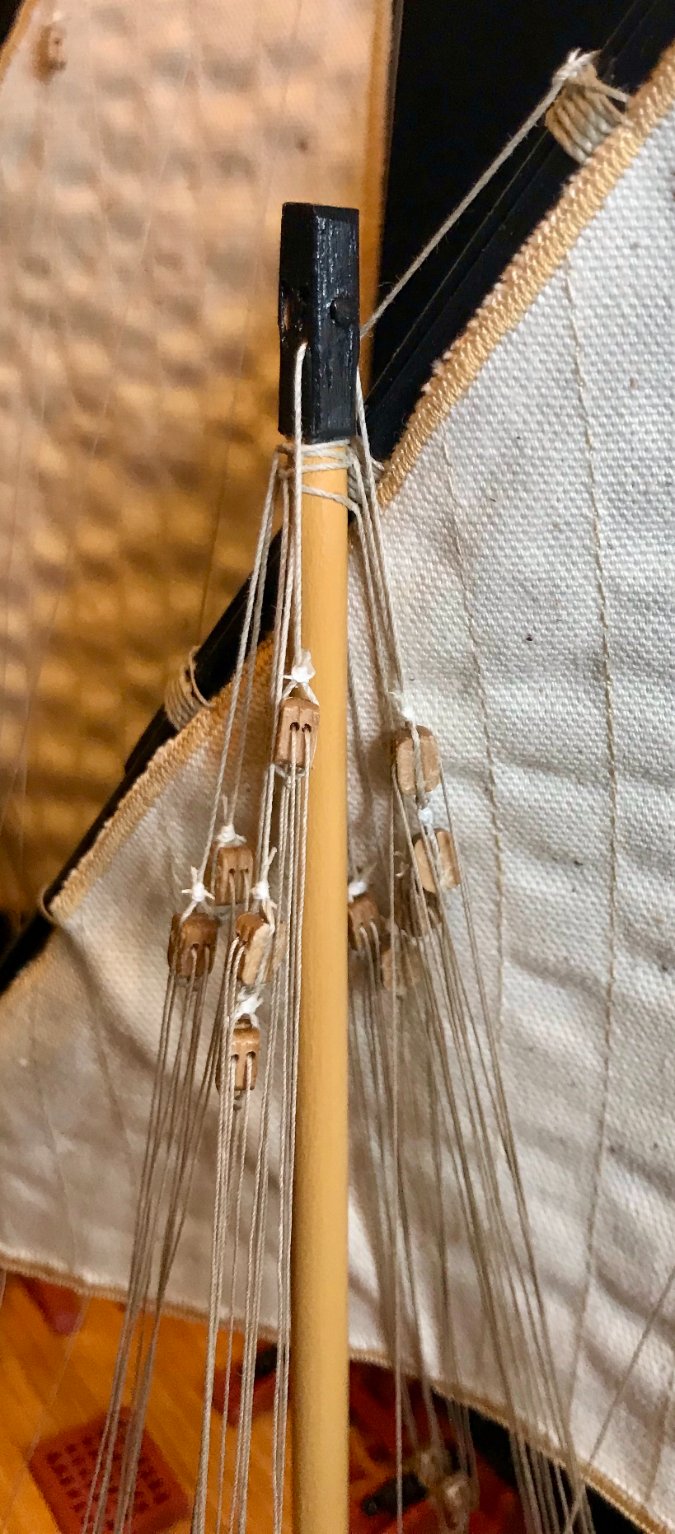
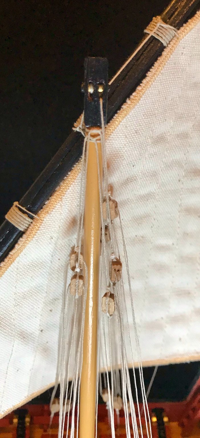
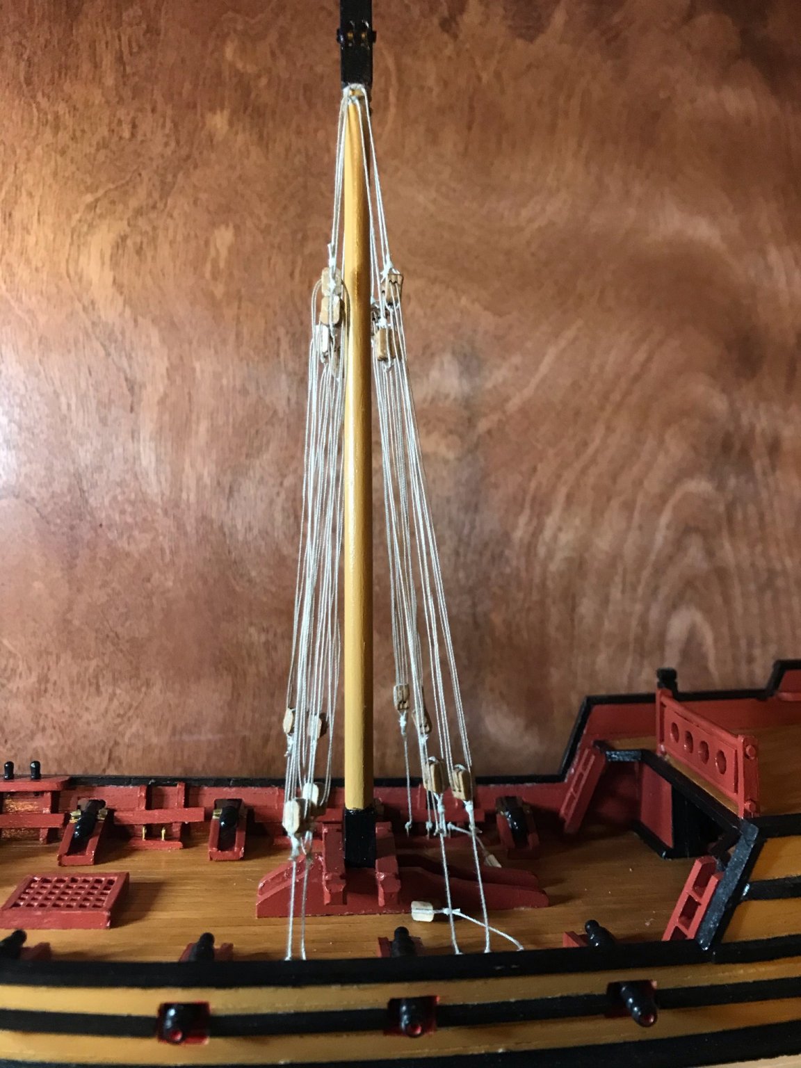
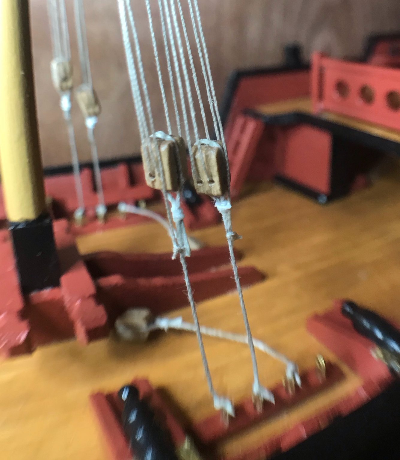
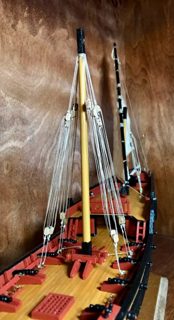
And now the mainstays are in! Adding the purchase ropes wasn't as challenging as I expected, largely because the holes drilled in the blocks are so clean. Mantua/Sergal did a really nice job with those! The biggest challenge was that these ropes are so close together that there just isn't any room to maneuver. I also can't seem to control the twisting of the blocks as the take on tension. I'm assuming that this is caused by knot placement and direction, but I'm just not sure. Forward and port views of the main stays. The remaining two blocks on the deck are for the halyards. Details of the pendants and lower blocks. Except for the twisting, I'm really pleased with how these turned out. All of the pendants have beckets, so the purchase lines are strung cleanly and correctly. I'm getting the hang of seizing the ends of ropes. And I even managed to tie off the loose end of the purchase ropes better than I did on the mizzenmast


-
Thanks, Bob! Another small step finished tonight. I seized the ends of the rope on the pendants of the mainmast stays, then attached them. The last step here will be stringing the purchase between the upper and lower blocks, then I'll finish up the antenne and mainsail.

- 79 replies
-
- 1
-
-
- sergal
- sciabecco francese
- (and 1 more)
-
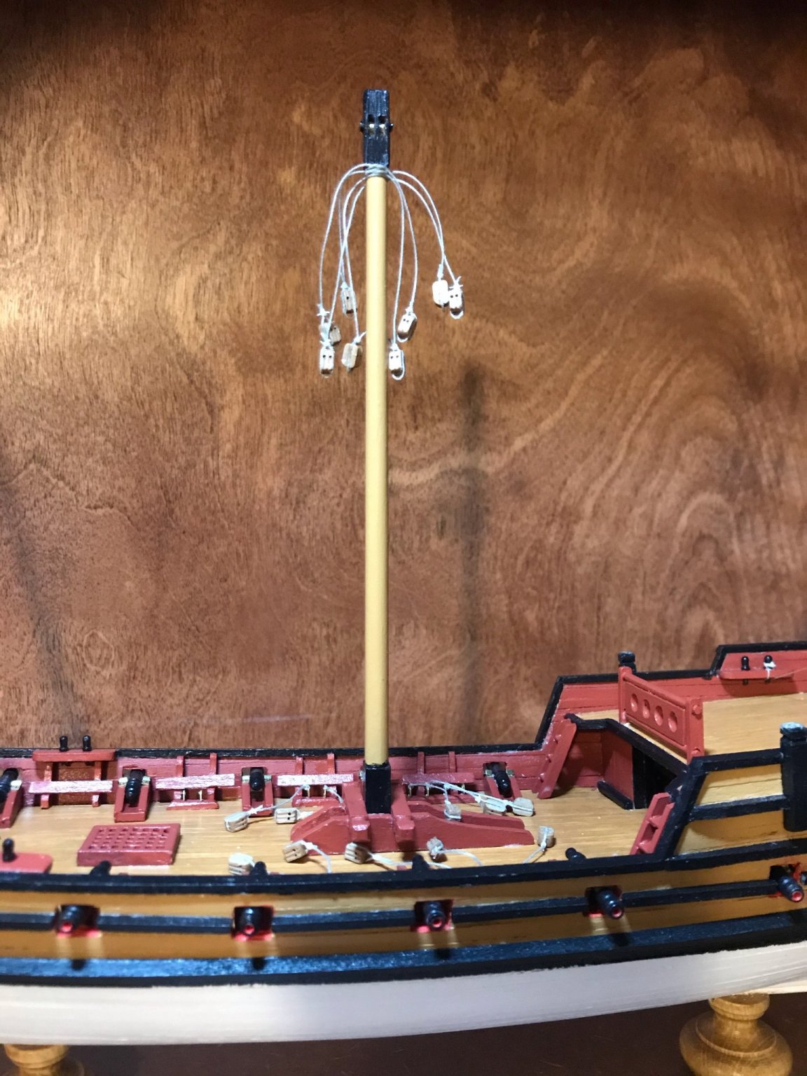
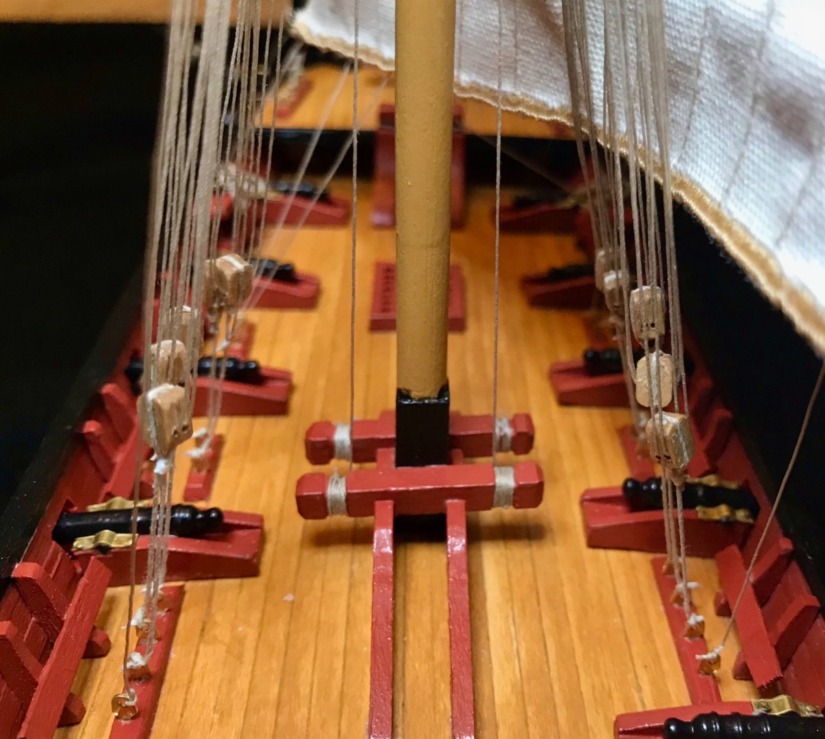
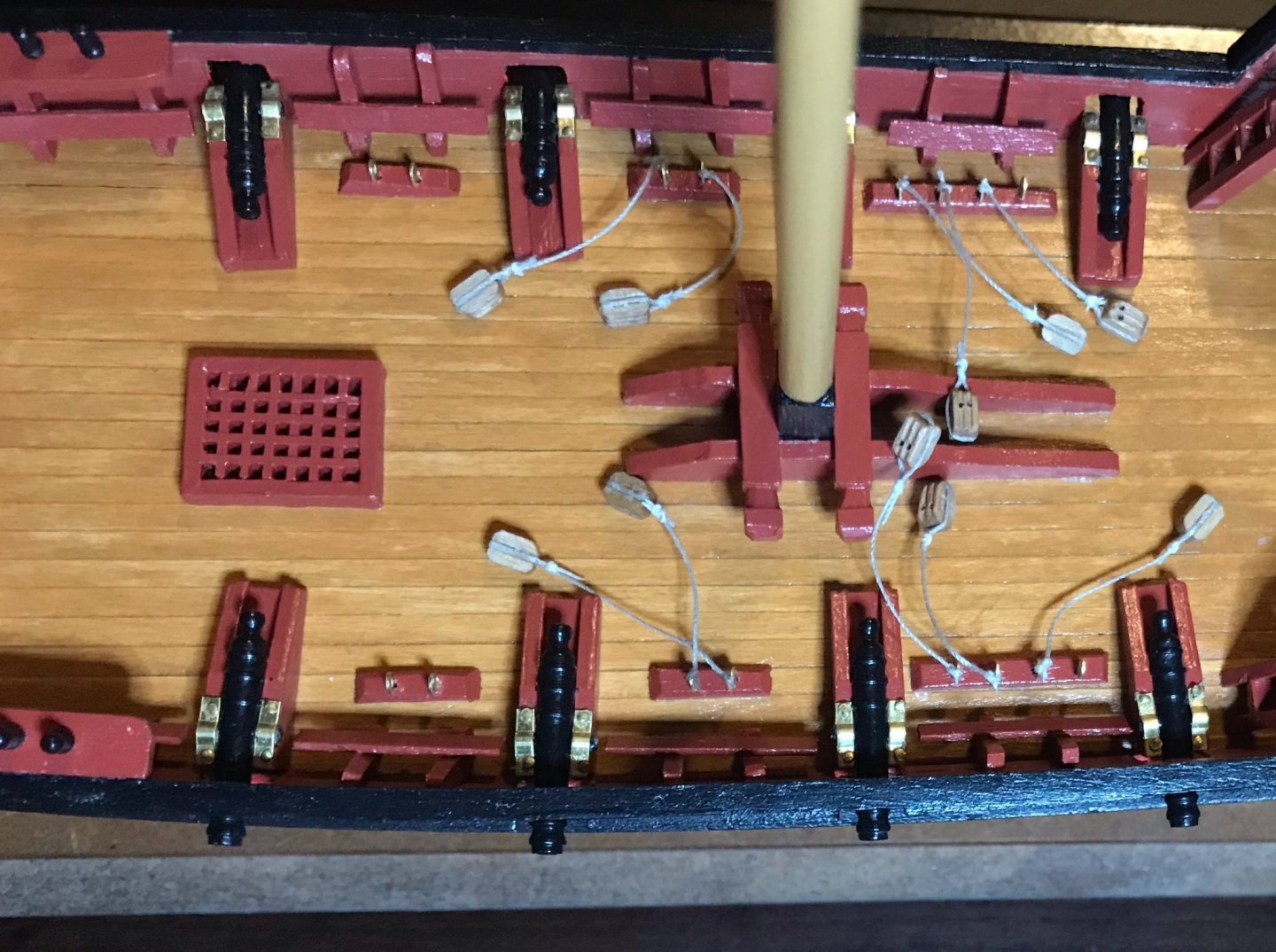
It's been a busy week, so I haven't gotten much done on the xebec. The next big goal is to hang the mainsail. Toward that end, tonight I seized the ropes on ten blocks (I'd attached the ropes to the blocks a couple weeks ago), then tied those blocks down to the eyebolts on the deck. The eight blocks closest to the mast are the bottom parts of the stays. The two to the far right (one on each side) are the bottom parts of the halyards. The last eyebolts on the right are the attachment point for the standing ends of the garantes. Those ropes will each run from the eyebolt, up to a single-sheave block tied onto the antenne, then back down to a belaying pin on the aftdeck. Next step: preparing the antenne—blocks will be tied on for the garantes and ostes, then the sail will be tied on.
- 79 replies
-
- 2
-
-
- sergal
- sciabecco francese
- (and 1 more)
-
I wasn't planning to finish hanging the mizzen sail tonight. I was just going to do some of the prep work and hang it tomorrow or Friday. But at a certain moment, I had reached a point of no return and had to finish the job all the way. 5-plus hours later, it's done and I'm mostly satisfied with it. At the very least, I've learned about that will be helpful when I hang the main- and fore-sails. My original plan for today was to sew a brass ring into the clew of the sail and to attach the pendants to the antenne (for the halyards and the ostes). But then I ran into a problem with the halyards . Because of the pendant blocks on each halyard, the sail cannot be lowered all the way to the deck; as a result, the halyard pendants have to be attached to the antenne directly on the ship; further, the sail has to be attached to the antenne first. My plan to hoist the sail properly was thus crushed. So, the new plan was: 1. Sew the brass ring into the clew. 2. Attach the sail to the antenne, which I did using ten individual loops. 3. Attach the pendants for the ostes. 4. Run the halyard pendants through the masthead and tie them onto the antenne. 5. Run the middle segment of the halyards through the purchases and tie off on belaying pins. 6. Run the ostes from the sternsprit, through the clew, through the pendant blocks, and tie off on belaying pins. 7. Attach the ources to the forward end of the antenne and tie off on belaying pins. For the main- and foresails, I'll be able to do the ources before the ostes, which will help a lot. Things went mostly well. The bottom tie on the sail slid up just a little bit before the FrayStop glue dried, so the sail is a little loose there. The portside halyard is a bit too loose—I'm not certain whether the antenne shifted on me or whether the thread stretched out from repeated pulling. It's not bad, but pretty noticeable to me. The stern belaying pins were really frustrating. There just isn't enough room to maneuver, even using angled tweezers. The starboard ones look better because I did them first, when there was still room to move around. On the port side, I ended up just tying off the ropes on the top part of the belaying pin. In the end, I'm going to put a couple loops of thread on top of all the belaying pins, so I wasn't too worried about belaying the ropes perfectly and I cut the ropes close to all the knots. Port side, full view. Detail shots of the mizzen sail from the windward (port) side and leeward (starboard) side. Detail of the rigging from the windward (port) side.

- 79 replies
-
- 2
-
-
- sergal
- sciabecco francese
- (and 1 more)
-
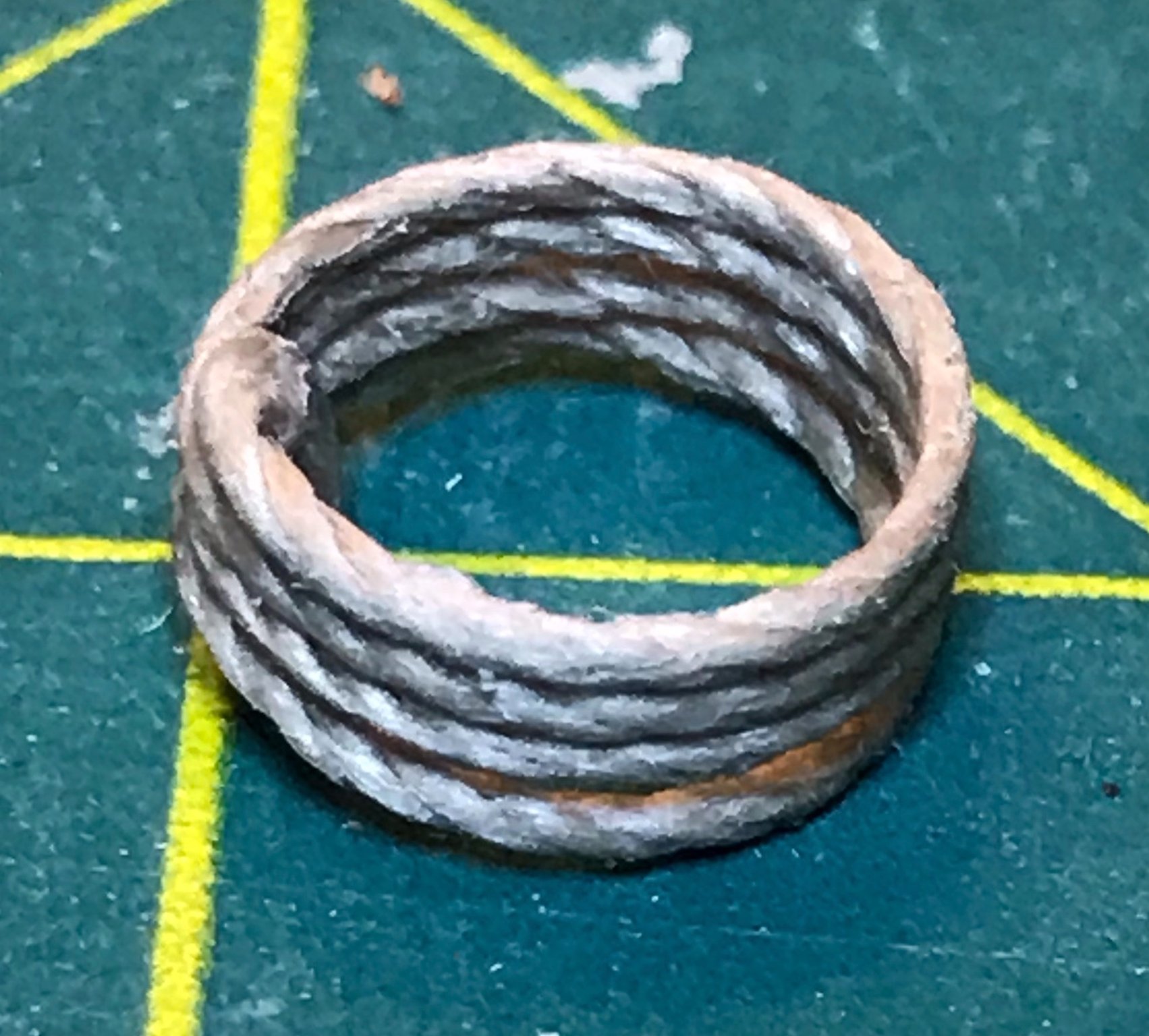
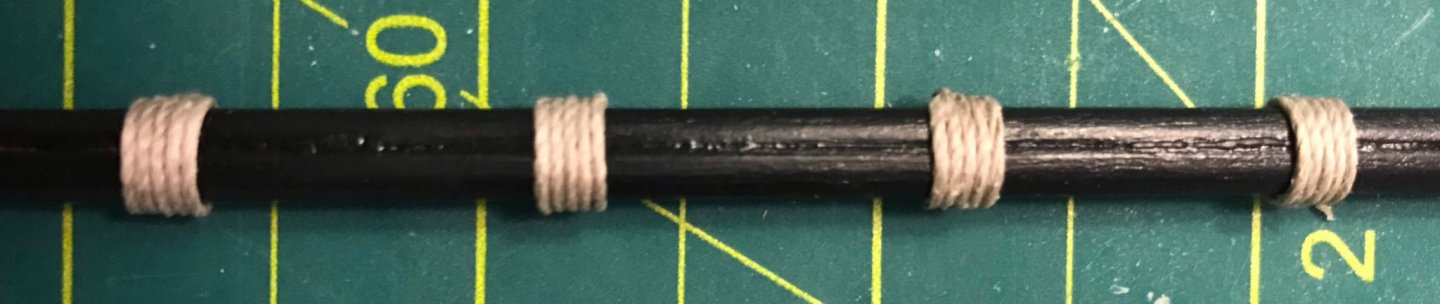
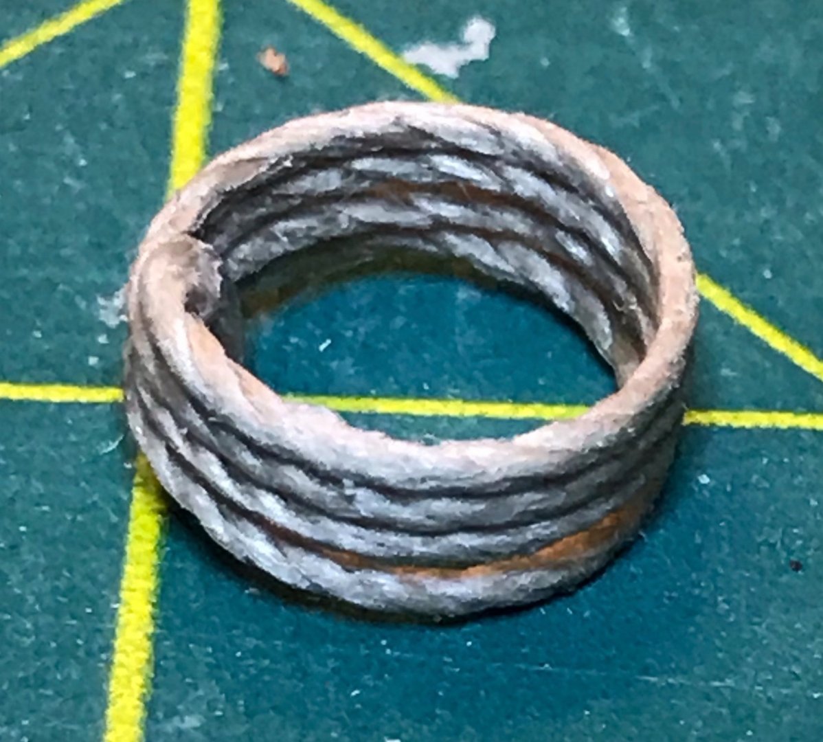
Put in a little time tonight on the mizzenmast antenne, working on the wooldings. I'm thrilled with how they turned out! I am planning a nice photoset showing the various stages in rigging the antennes....but, well, I'm just really pleased with how these look and thought I'd show off a little. (Thanks for indulging me!) The photo shows the clean side; the knot is on the back. But even on the knot side, the loops are lying against each other this nicely! After putting these four wooldings on, I got nervous about the thread supply. So, I measured the entire spool and cut the pieces necessary for the two anchor cables and the 10 wooldings on the other antennes. Had the kit come with the amount of 1mm thread promised, I would have run short. Thankfully, there was a bit extra, so I had enough for everything. After cutting everything, I made a coil of cable that I'll eventually put on the foredeck, near the cable channels and cat davits.
- 79 replies
-
- 1
-
-
- sergal
- sciabecco francese
- (and 1 more)
-
Hi Bob! I know what you mean about the rigging. Although it can be frustrating with my big clumsy fingers, there's something really satisfying about seeing the rigging going up. One big perk of having the masts already installed is that all of the rigging will be functional (at least until I put Fray-Check on the knots!). Once each antenne is ready, it will be hoisted into place by its halyards, then aligned via the ource and oste lines, and stabilized in place with the garante lines. The staysail will be hoisted by its halyard, too, and then its clew will be tied down. No way forward now but slow and steady, with a focus on improving my skills. One nice thing is that the blocks that came with the kit are much, much better than what I've seen in my previous kits. These are walnut, shaped consistently and well, and the holes for the sheaves are all drilled out cleanly. There's a little inconsistency on the placement of the holes—within a tolerance of maybe .5mm—but all 50 blocks are usable. Some time next week I'm hoping to hoist the mizzen sail. I'm really looking forward to seeing that—a few of my colleagues are, too, since my ships are all visible in the background during our Zoom meetings!
- 79 replies
-
- 1
-
-
- sergal
- sciabecco francese
- (and 1 more)
-
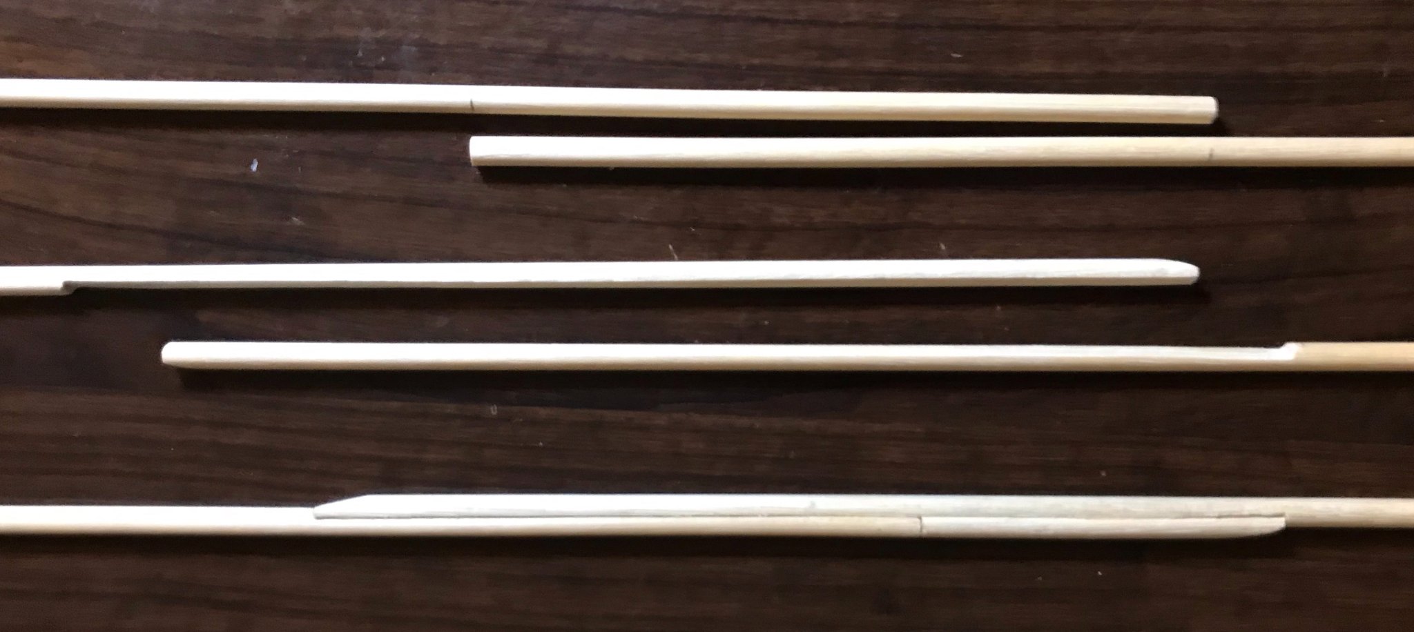
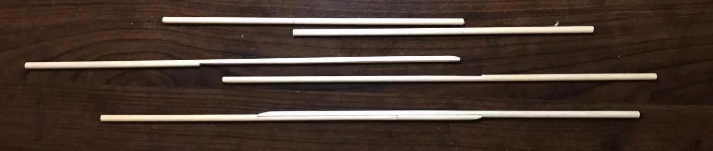
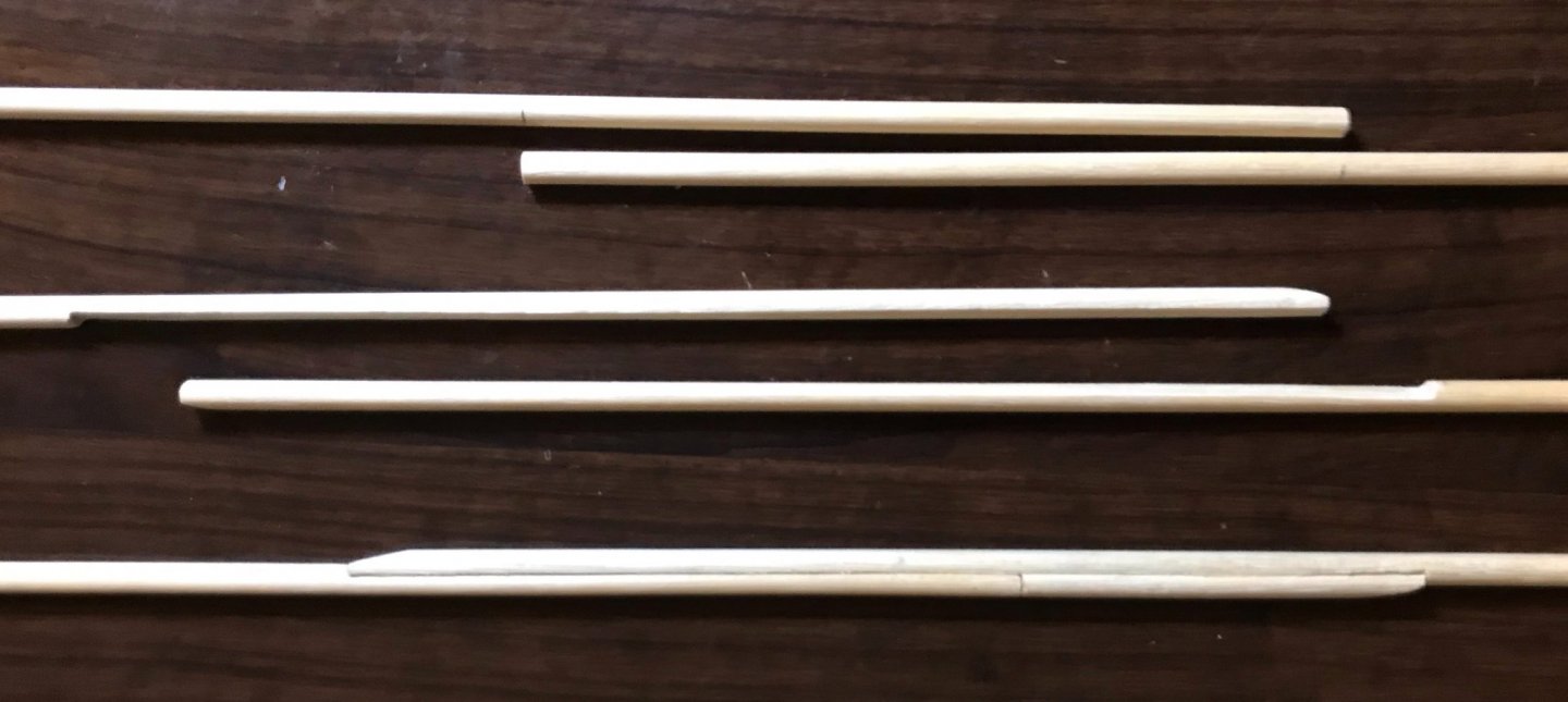
I've started the rigging now and am quickly remembering just how challenging this stage is! I've assembled the three antennes, though I still have some finishing work to do. (They're currently painted and partially finished, but they will need wooldings, pendants, halyards and sails before they're done. Each antenne is made of two pieces attached with a scarf joint. A small table saw would have made quick work of this, but since I don't have one my best option was a file, sanding sticks, and a lot of patience. Step 1: I measured the two halves against the sail to find my marks. Step 2: I used a square file next to the mark, making sure I had a right angle at the end of the joint and filing down to my target depth. Once I was done with the file, I used an 80-grit sanding stick to bring down the rest of the joint, using finer grit sticks to do the final leveling. I also tapered the ends of the joint. Step 3: Then I glued the two halves together. In the photos, you can see a full view and detail view of each of those steps; at this point I still needed to taper the ends of the antenne and do a bit of smoothing around the joints, but I did do that before moving into painting. A quick note, since you probably noticed the odd seam in the bottom pair in each photo: I screwed up and mismeasured the foremast antenne. Well...I measured and cut perfectly, I just looked at the wrong place on the plans and used the measurements for the mizzenmast antenne instead (the top pair in the photos). Since I didn't have enough dowels on hand to recut both halves, I had to make do and glue on an extension to one of the miscuts. Once I finished sanding and painted, the seam was invisible, but it's still pretty obvious in those photos As I add the rigging, I'll be working from back-to-front because the sails overlap and it'll be too awkward to do it in any other order. So, between coats of paint and finish on the antennes, I rigged the mizzenmast stays. And here I came face-to-face with a problem. In my previous kits, I've attached the stays to the masts before attaching the masts to the ship. But with the complicated mast partners, I've already attached everything firmly. So, I'm left with the awkwardness of rigging directly on the finished ship. So far, so mediocre. There are two stays on each side, though only the forward stay has a purchase (which I guess is the correct term for the two double-sheave blocks?). Things turned out reasonably well on the port side, but the starboard side is a bit of a mess. I pulled too hard at one point and had to replace the seizing on the pendant block (that went better the first time!) and afterward couldn't get the blocks to straighten out. I also couldn't get the lines as taut as I would have liked on that side. I should get better at this as I go, since I still have 18 more lines with this kind of purchase!

- 79 replies
-
- 1
-
-
- sergal
- sciabecco francese
- (and 1 more)
-
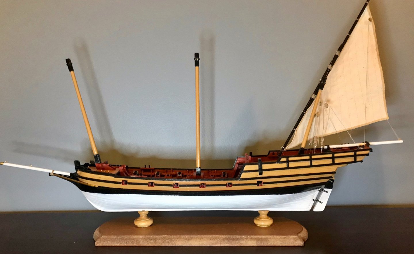
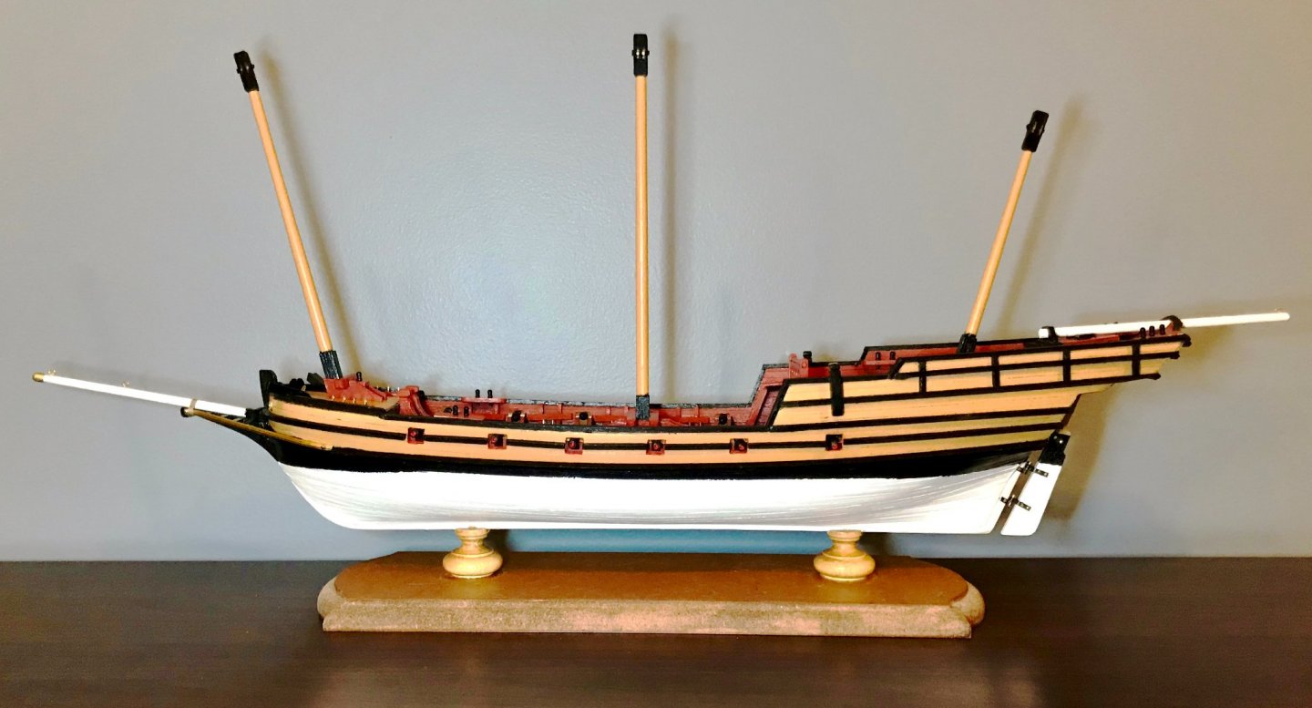
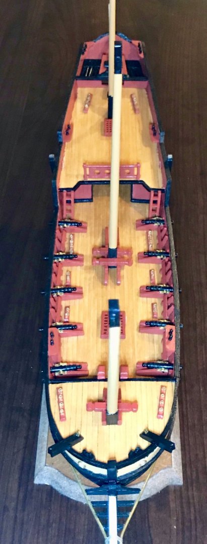
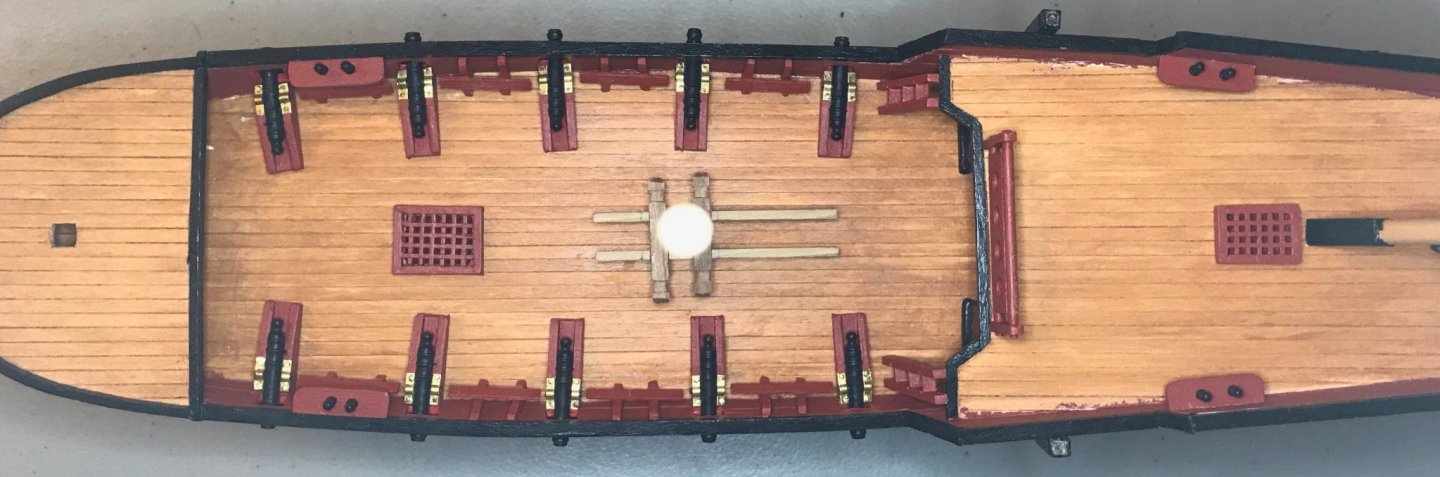
Time for another celebratory post! I've finished the deck fittings, so all that remains to do is the rigging! I've put on the first coat of finish, so figured it was a good time to take these photos. First, a few shots of the full ship from different angles. Then the bow and a shot of each deck. (Note: I'm waiting until everything else is done to reinstall the swivel guns.)


- 79 replies
-
- 2
-
-
- sergal
- sciabecco francese
- (and 1 more)
-
Thanks, Simon! That President kit looks like a fun challenge. I hope that the rigging plans for that one are better, since that part is so much more complicated than the xebec!
-
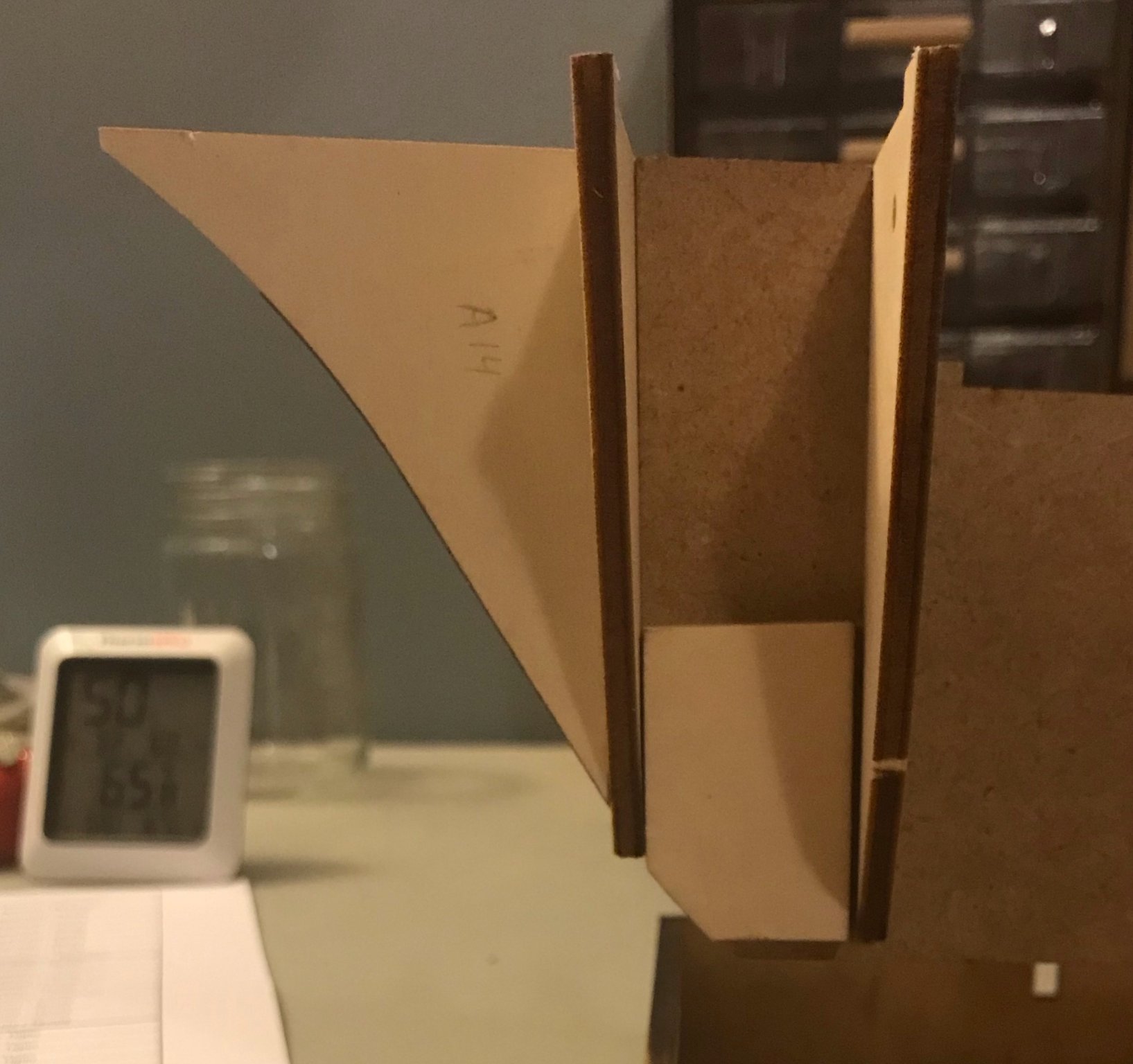
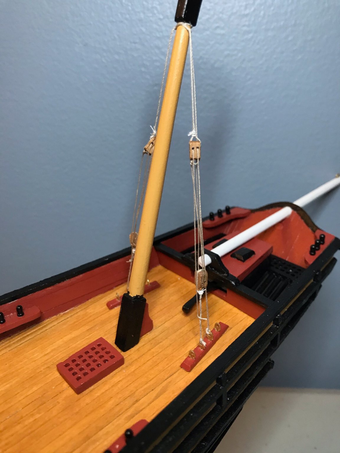
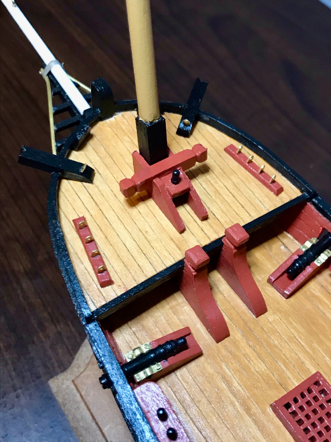
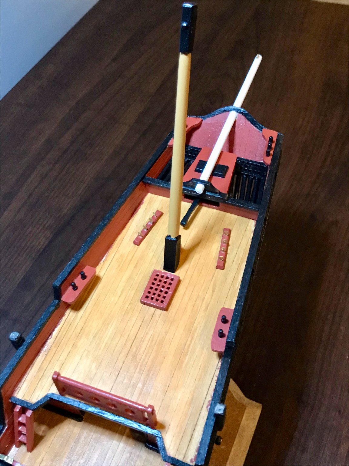
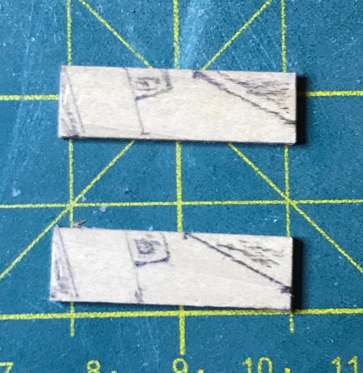
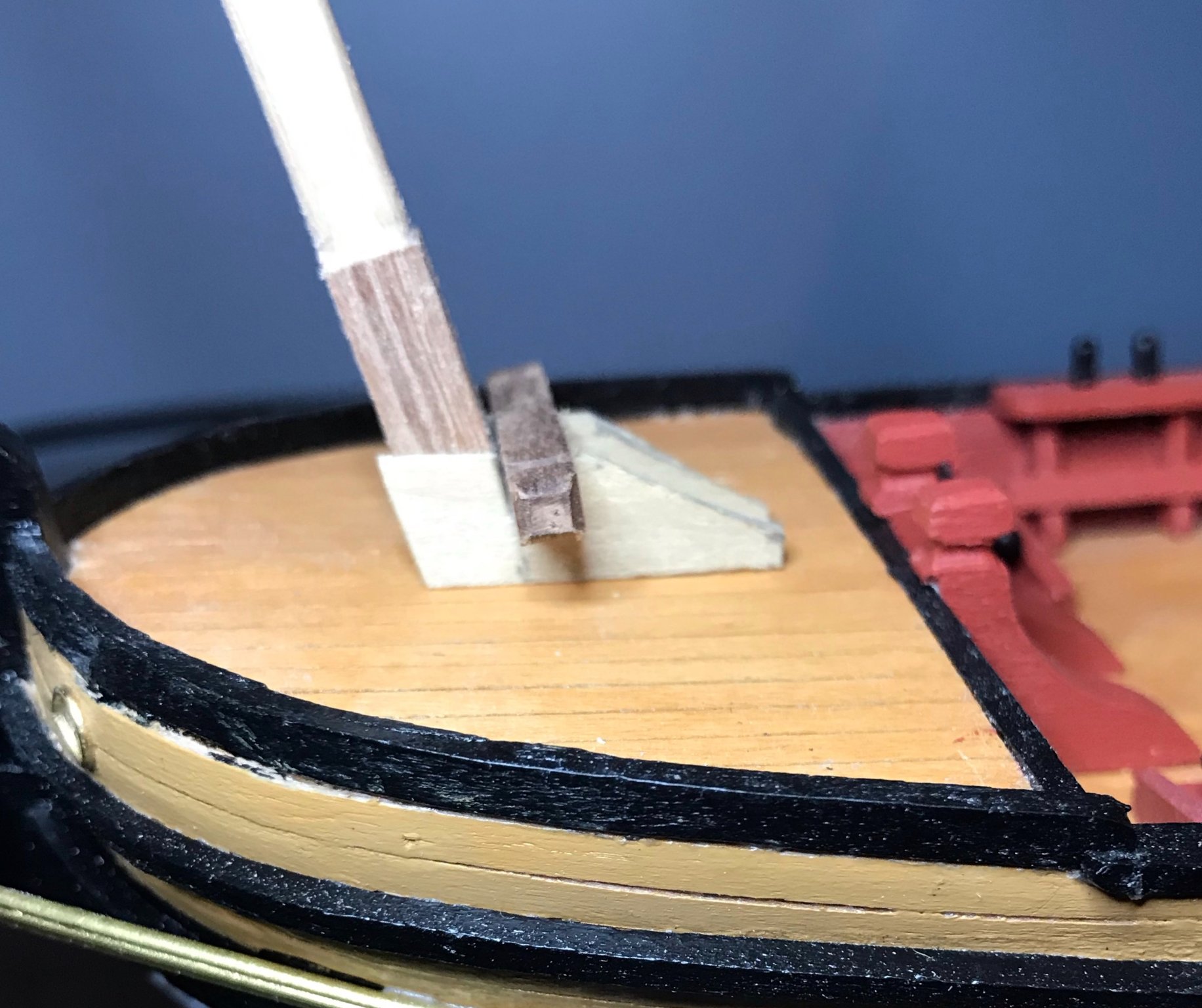
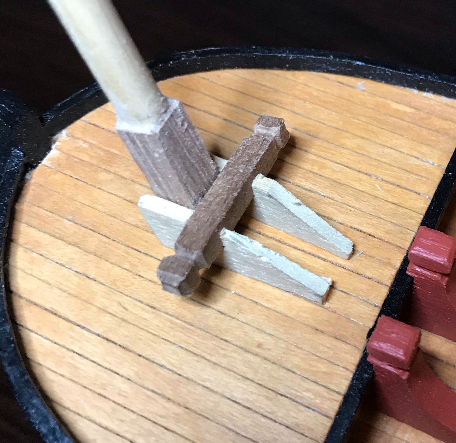
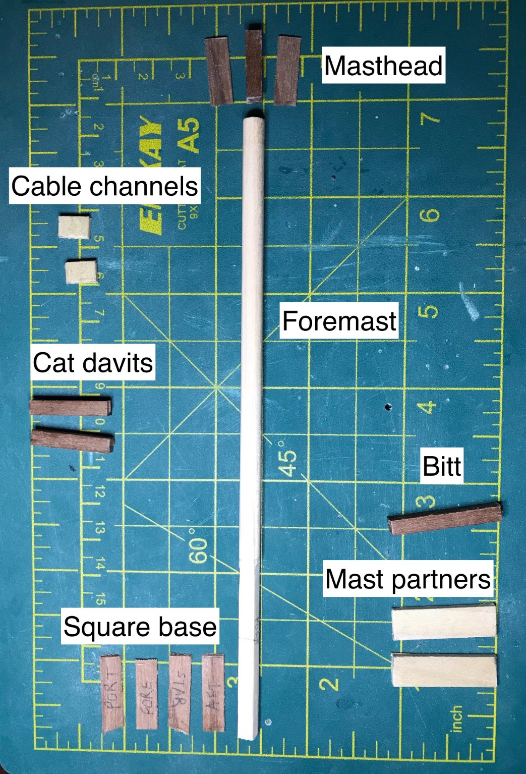
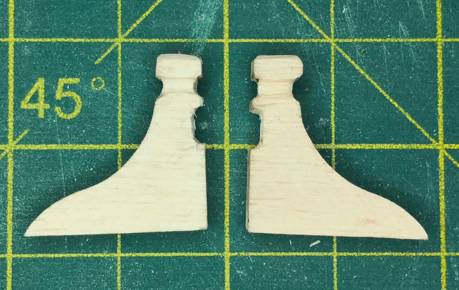
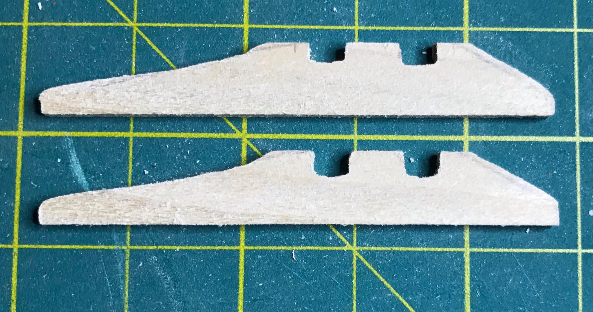
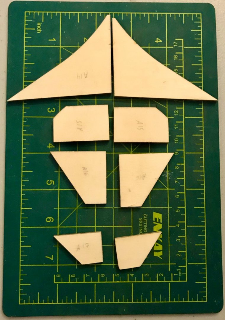
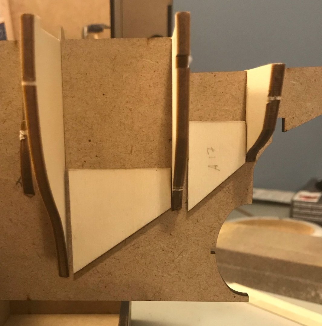
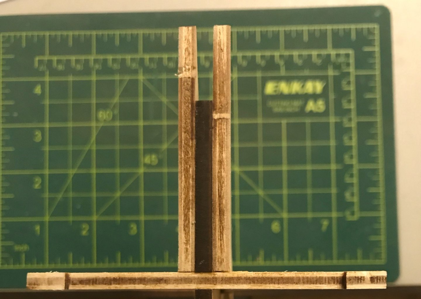
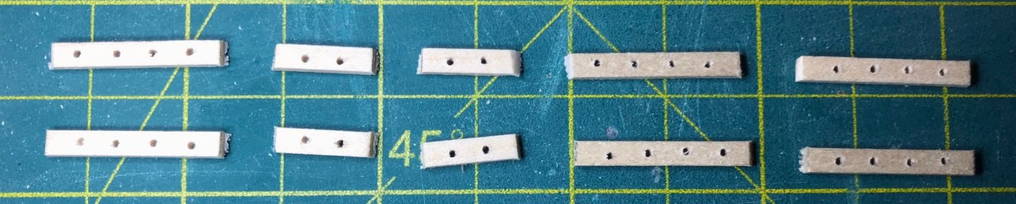
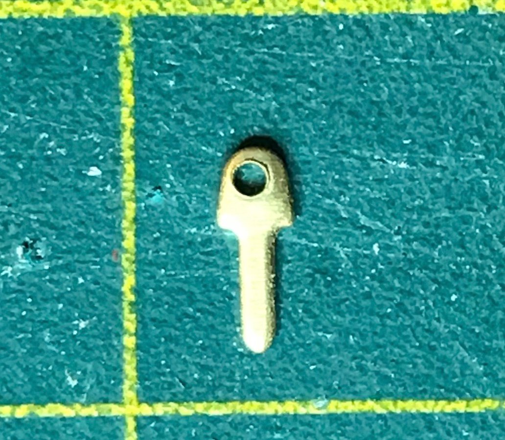
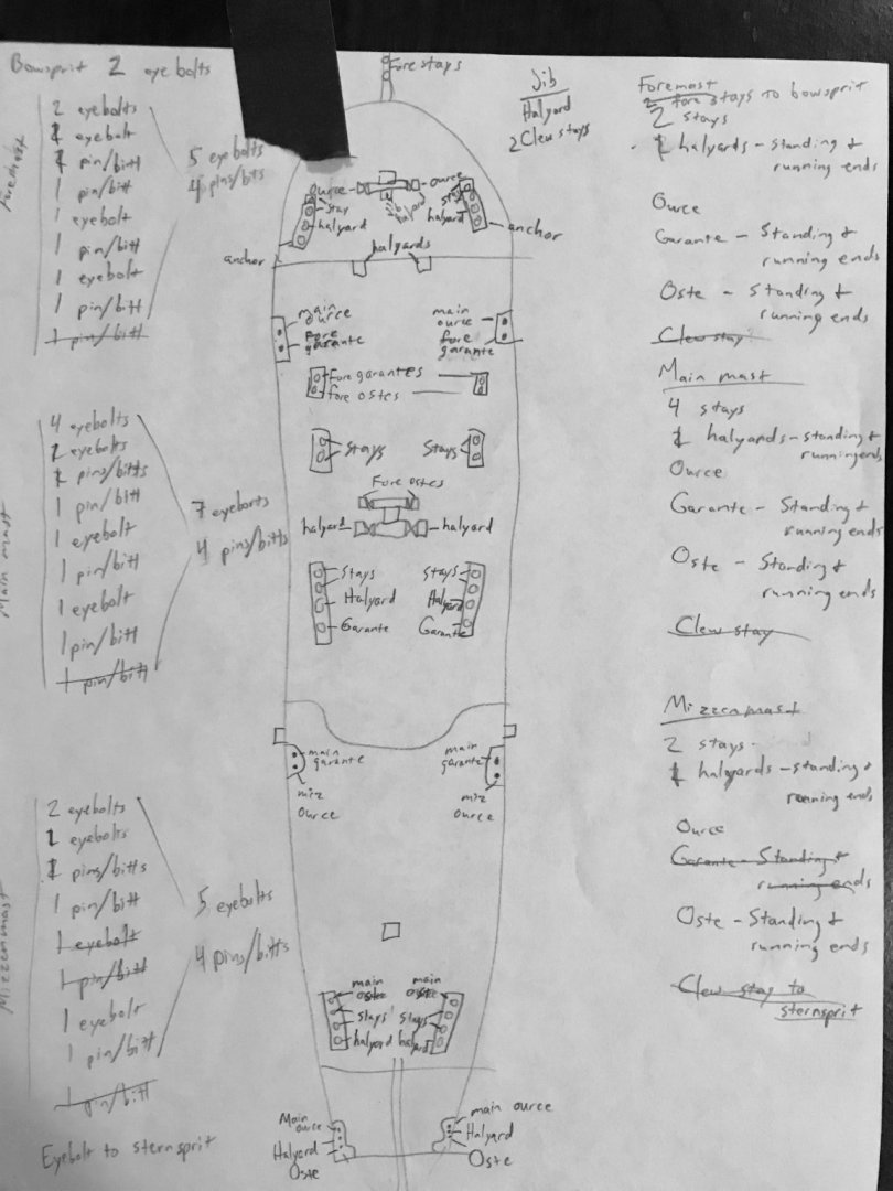
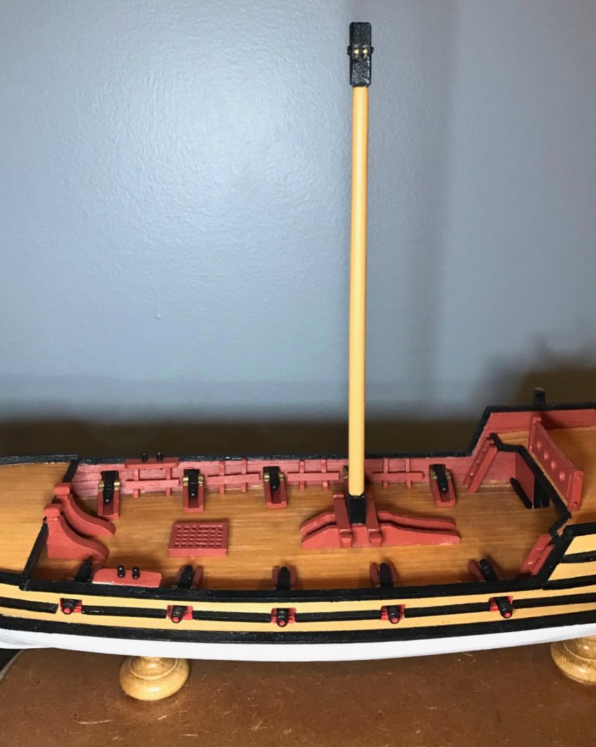
Things are moving along on the foredeck and I'm currently painting the various pieces. I thought I'd share some photos of the foremast assembly, since that's the most interesting part of the foredeck fittings. Taking care of the masthead, squarebase, and bitt were all straightforward and similar to what I've shown in previous posts about the other two masts. However, the mast partners are significantly different this time. The mast is raked and the forward edges of the partners line up with the mast. The bitt rests on top of the partners and against the mast, so needs to be tipped forward a bit. And, of course, the after end slopes downward. So, I started by marking the triangle that needed to be cut off from the forward end (left side of the photo), then marked a line for the after side of the mast. That allowed me measure out the forward side of the bitt; with a couple 90-degree angles, I measured the bottom side and then connected the dots for the after side (the shaded square in the middle). After that, I just drew a line from a point 2mm behind the bitt to another point 2mm above the deck (giving me the triangle on the right side of the photo). After cutting out the partners, I did a quick dry fit and snapped some photos before finishing the sanding. Although I don't have a photo of it yet, I also added a 6x6mm square attached to the after side of the bitt and the partners; the plans don't call for it, but I needed a place to belay the staysail halyard. Once all of the painting is done and these pieces are installed, I'll add some final photos. Tonight, I also started preparing the only remaining part of the deck fittings: the strips of eyebolts mounted on the decks. As I've mentioned previously, the rigging plans for the kit are problematic, especially if you are including the sails. There aren't enough anchor points, so many of the eyebolts and belaying pins have multiple ropes—as many as 4!—on one anchor point. So, I'm adding some strips and expanding some others. From front to back on each side, the plans call for strips of 3-2-4-3 eyebolts. In my rigging plans, however, that has become 4-2-2-4-4, as you can see in the first photo (forward is the left side). The second photo shows the eyebolts provided in the kit, mostly because they were not what I expected. Rather than being shaped from brass wire, they've been stamped out of a brass sheet. Not sure how common that is, but it's definitely not what I've seen in my previous kits. Also, an updated shot of my rigging plan. (Note that I've gone back and forth between the terms staysail and jib...still getting the hang of the terminology! Also misused the term "clew stay"...the key thing is that I know what I mean, right?)


- 79 replies
-
- 1
-
-
- sergal
- sciabecco francese
- (and 1 more)
-
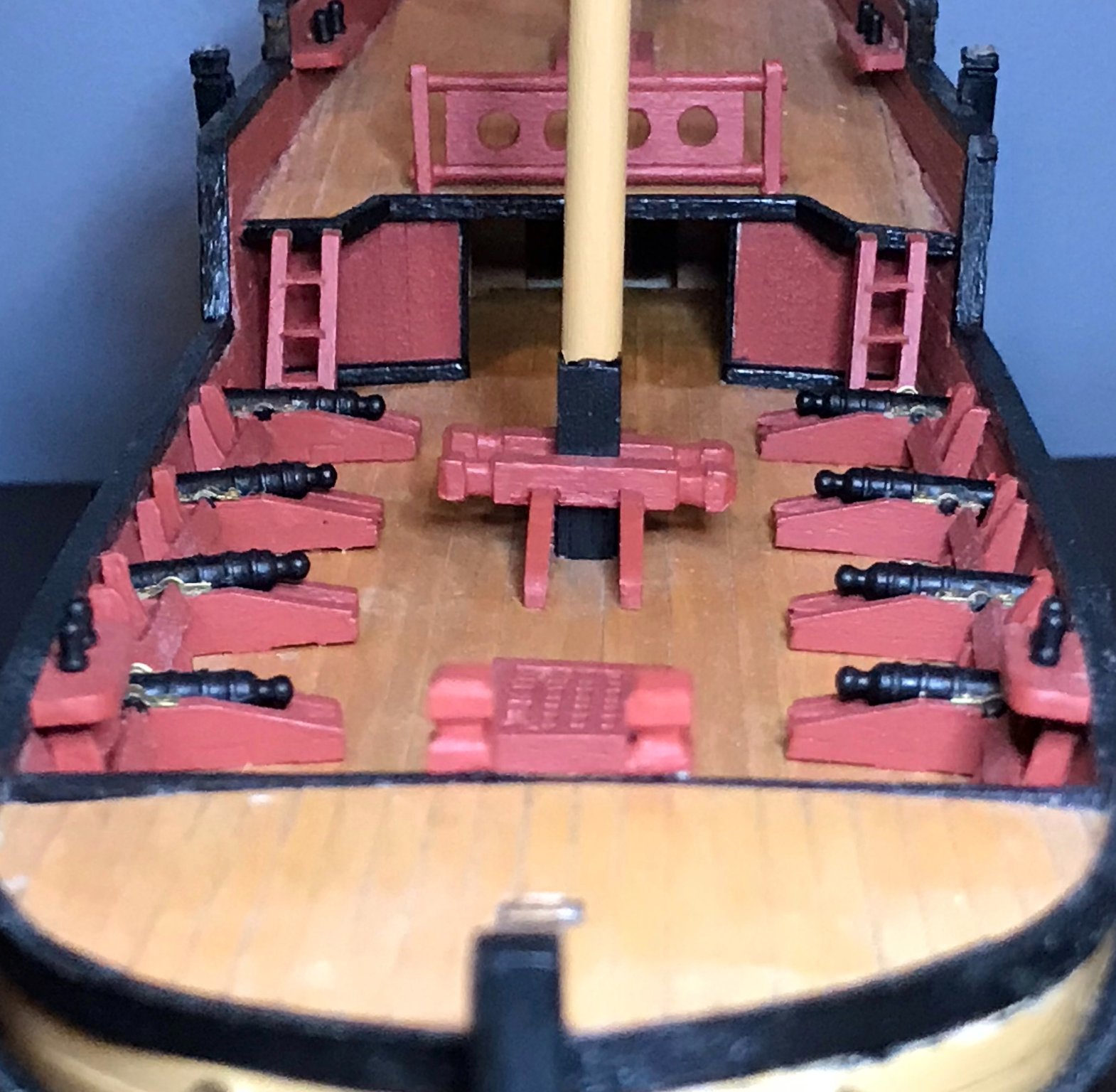
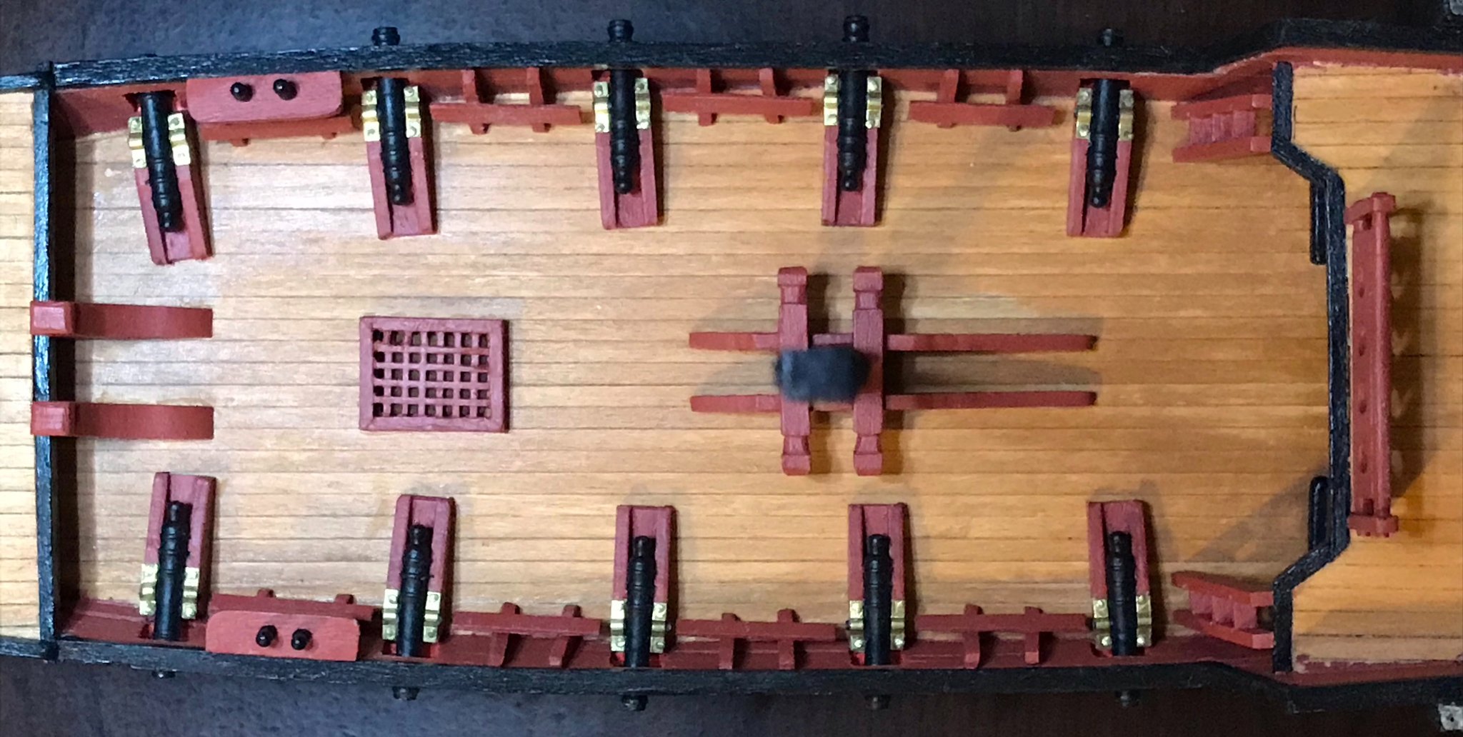
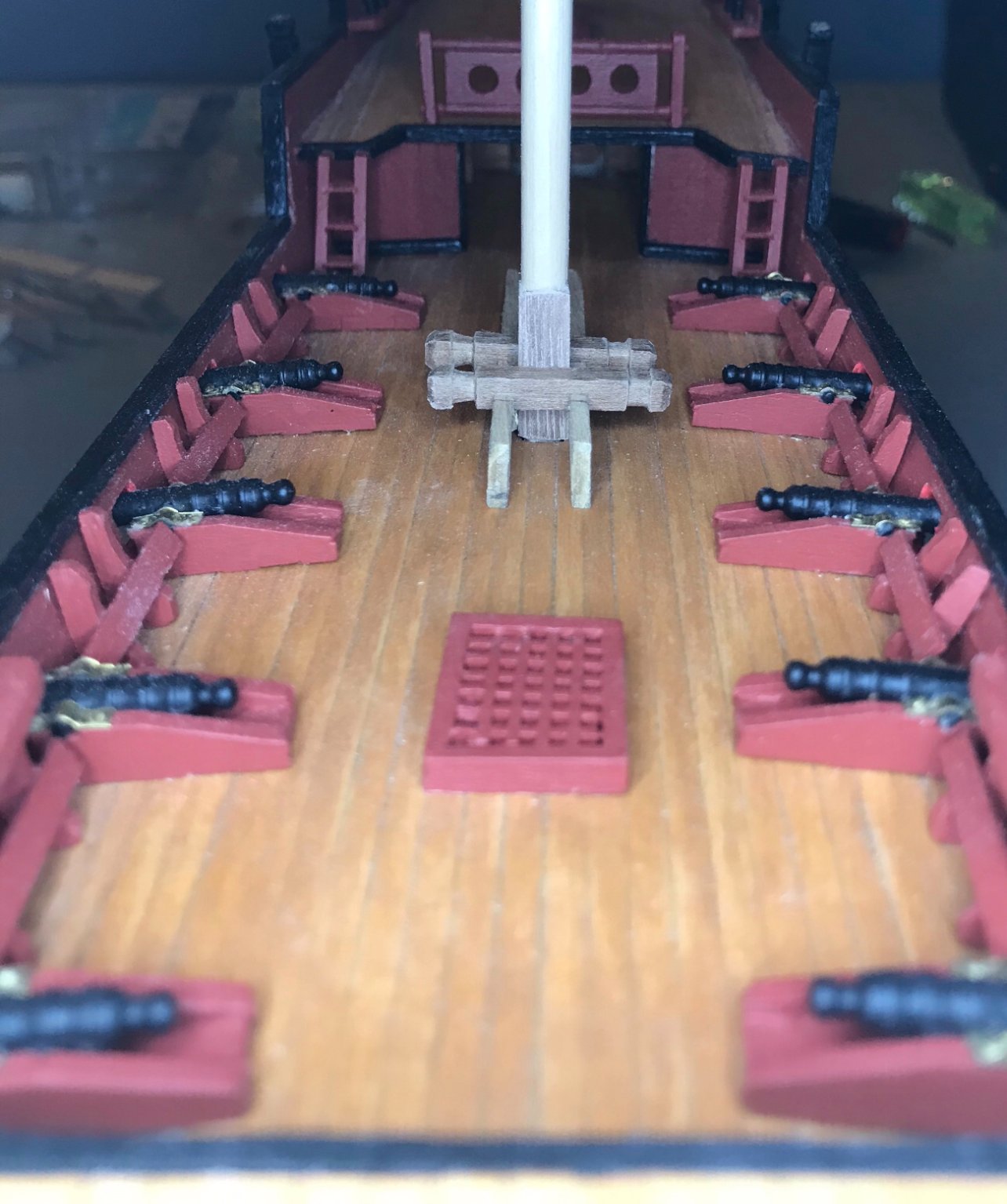
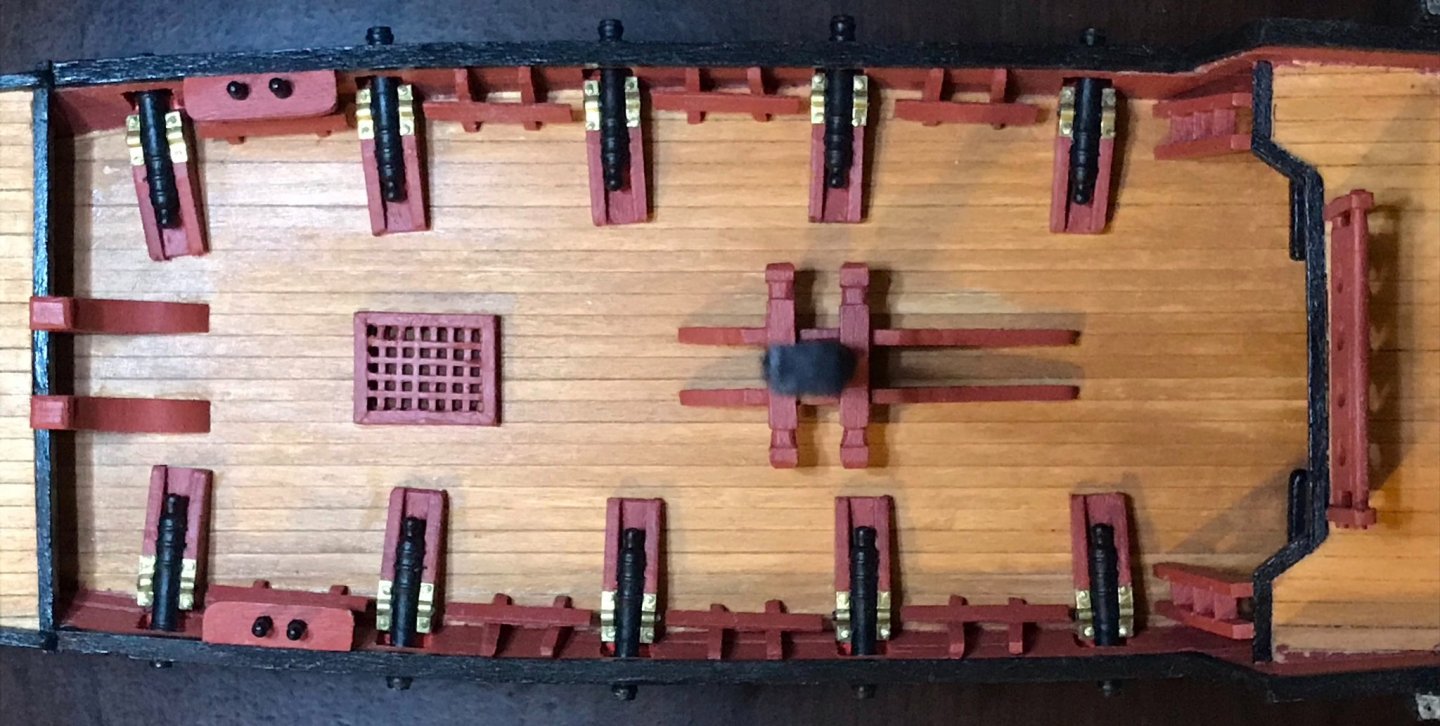
I got a lot done yesterday and today. One of the pleasures of virtual conferences is that my desk and my worktable are so close by...so during the panels I've been working on the xebec while listening to the speakers. (I've taken a lot of notes, so I'm not completely tuning out the conference!) First up, some photos of the maindeck, which now has all of the fittings installed except for the strips of eyebolts. The bitts are a little crooked because, once the were painted, the fit was so snug! It's a little bit exaggerated in the photos, but there in real life, too. I've also cut out and begun working on the fittings for the foredeck and foremast assembly. I've actually shaped the cable channels, cat davits, and bitt, in addition to partially assembling the masthead and square base. Photos will come in the next post. One more day of the conference, so the rest of the foremast assembly should come together very quickly...especially since I've got the hang of assembling the masthead and square base now.

- 79 replies
-
- 2
-
-
- sergal
- sciabecco francese
- (and 1 more)
-
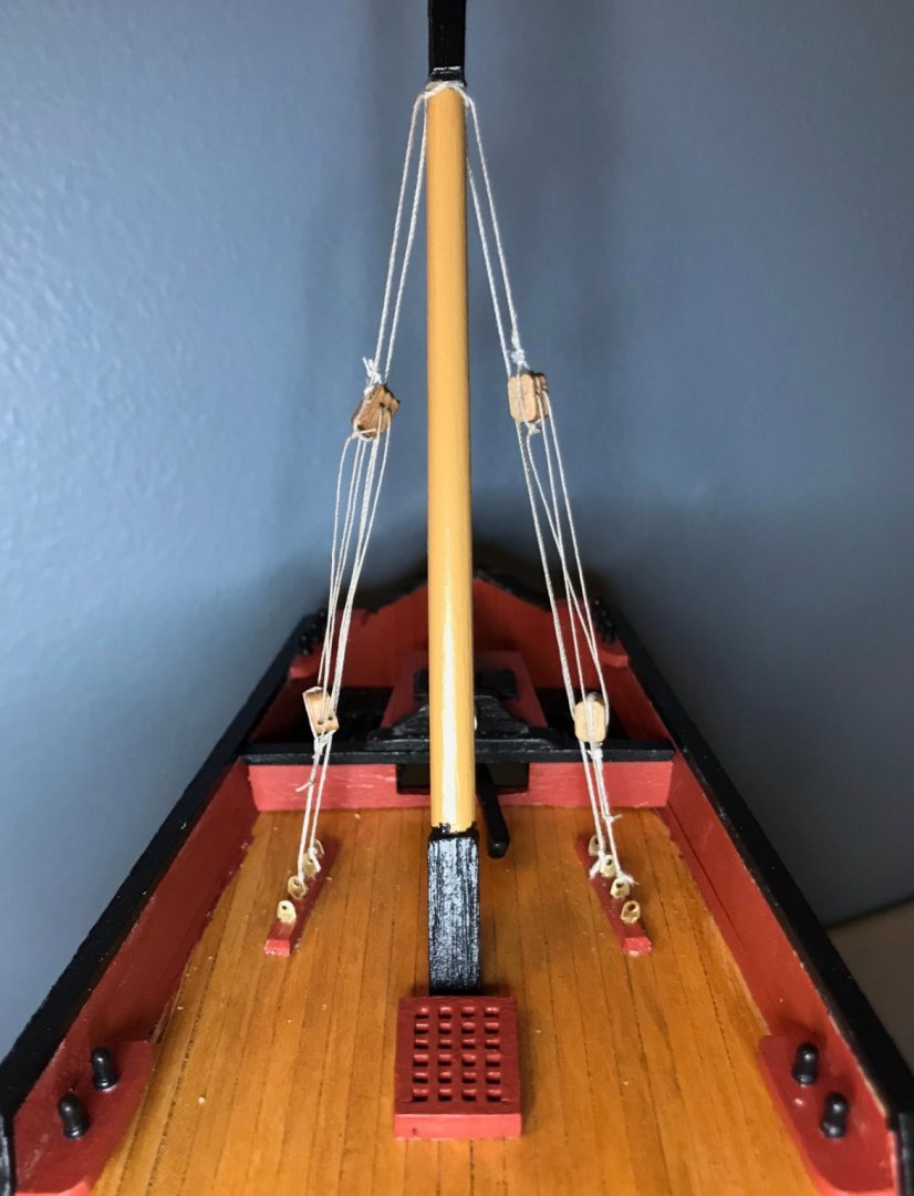
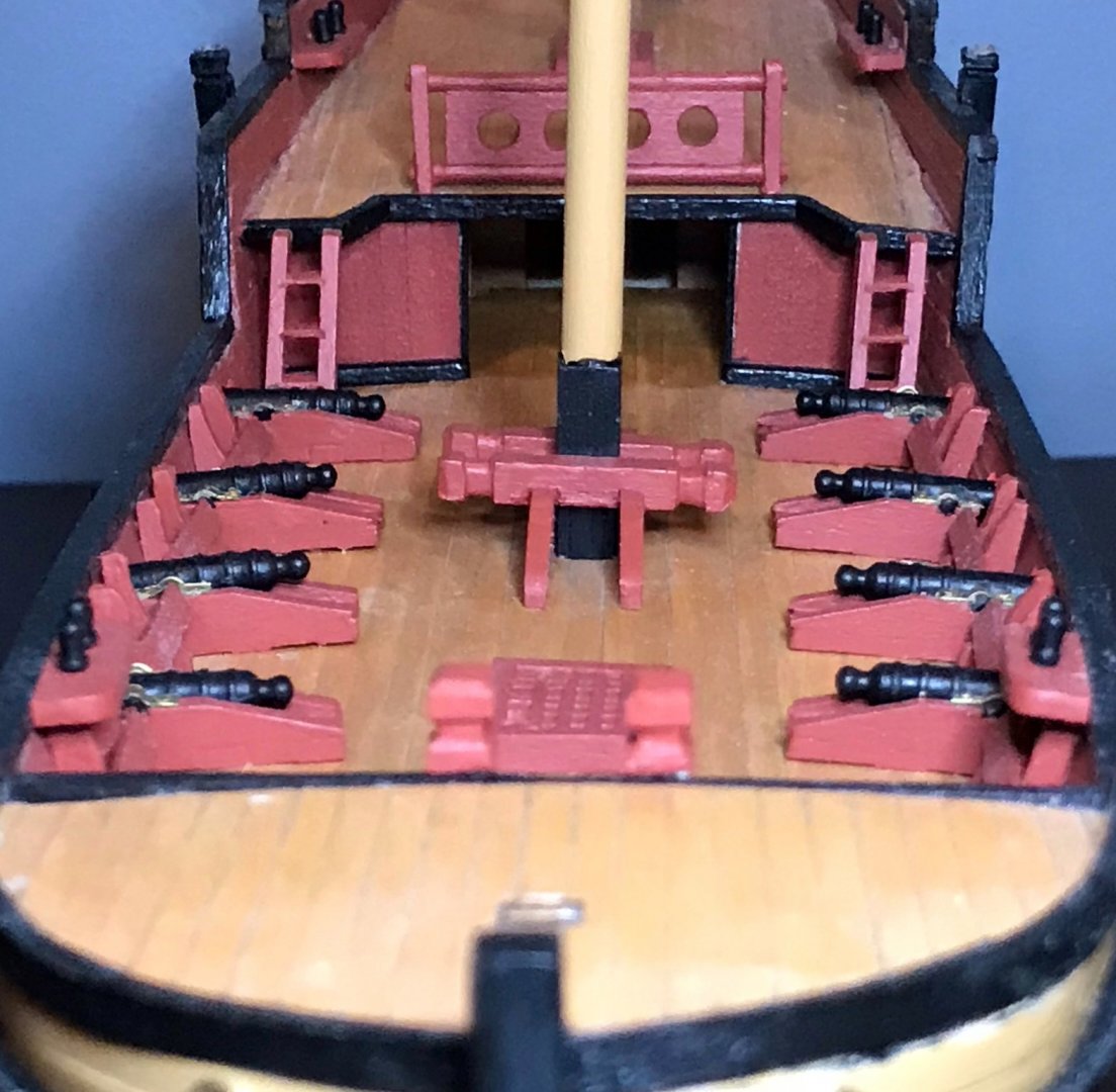
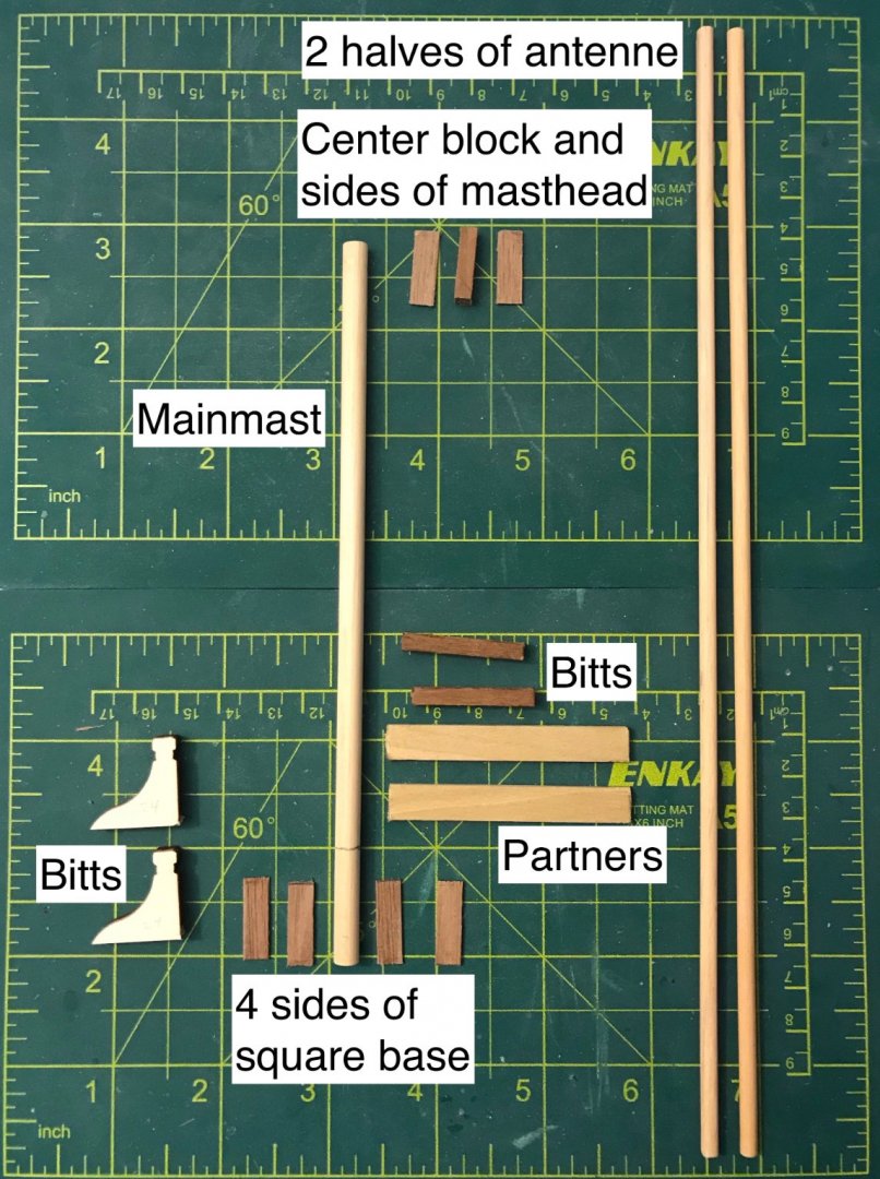
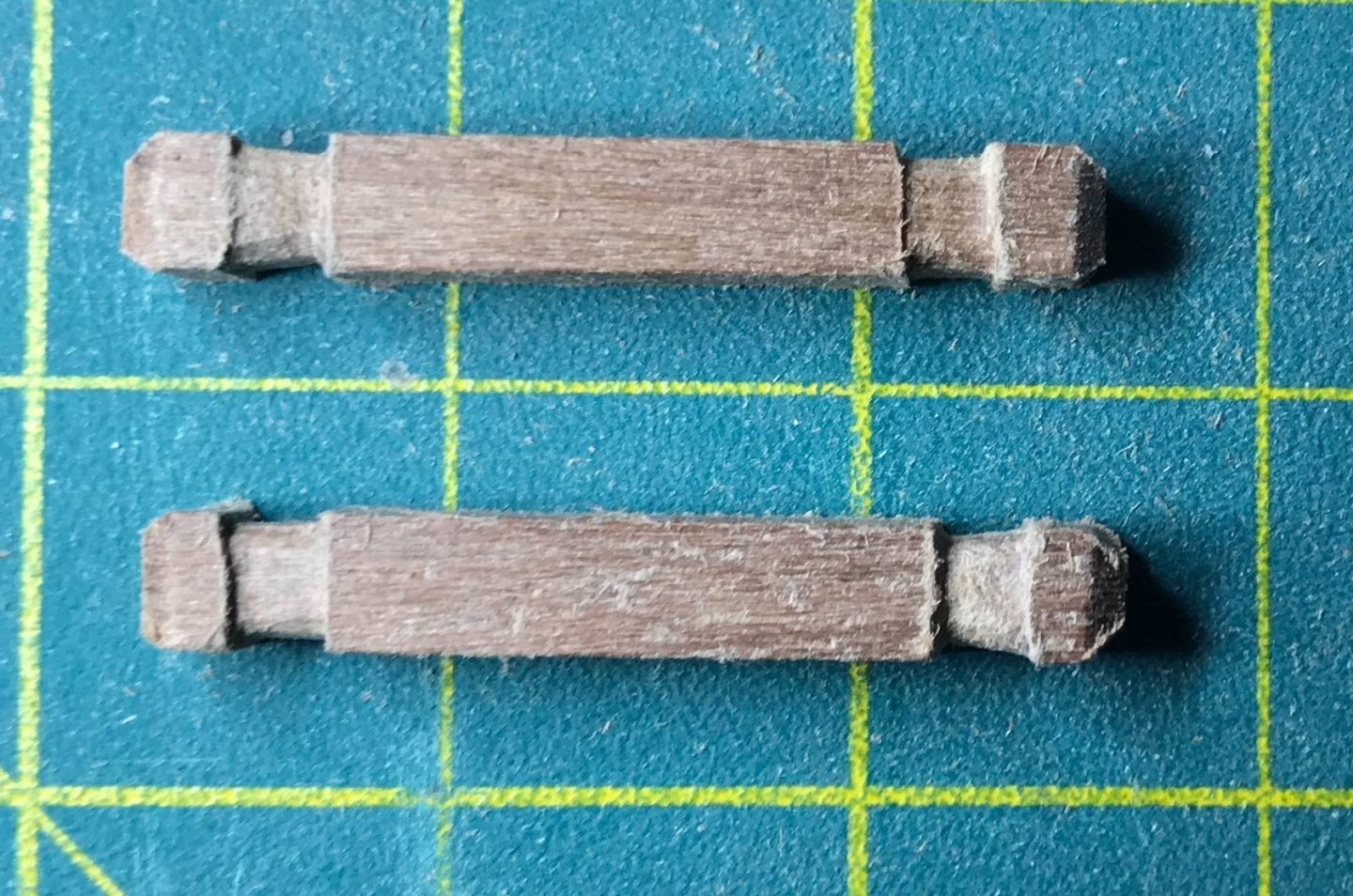
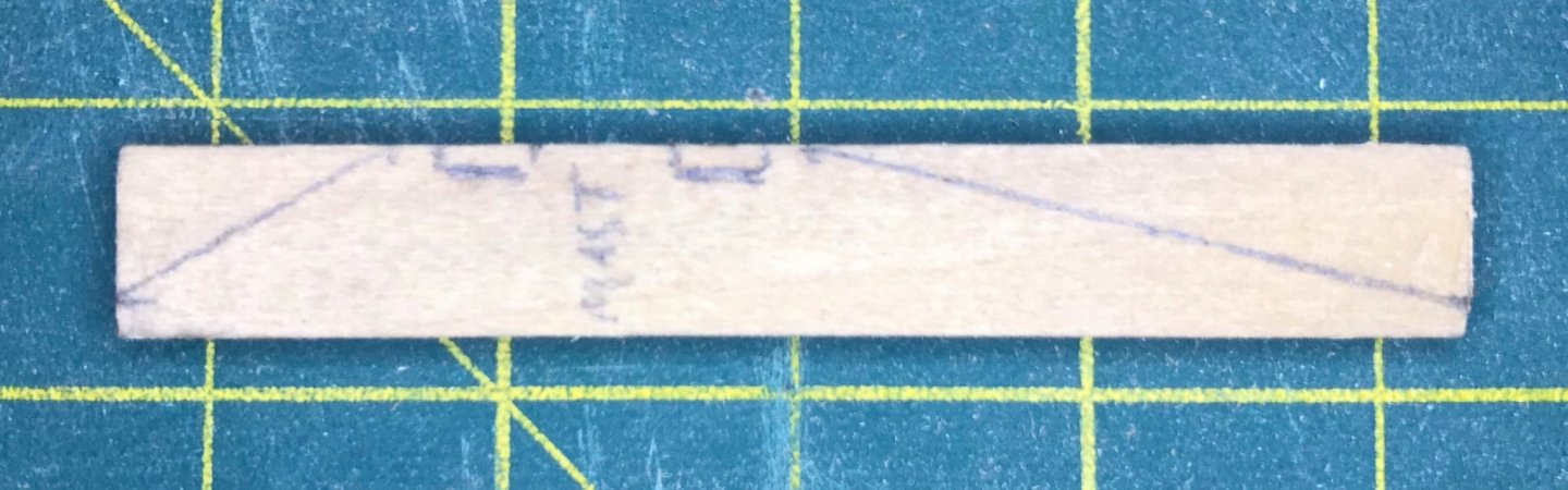
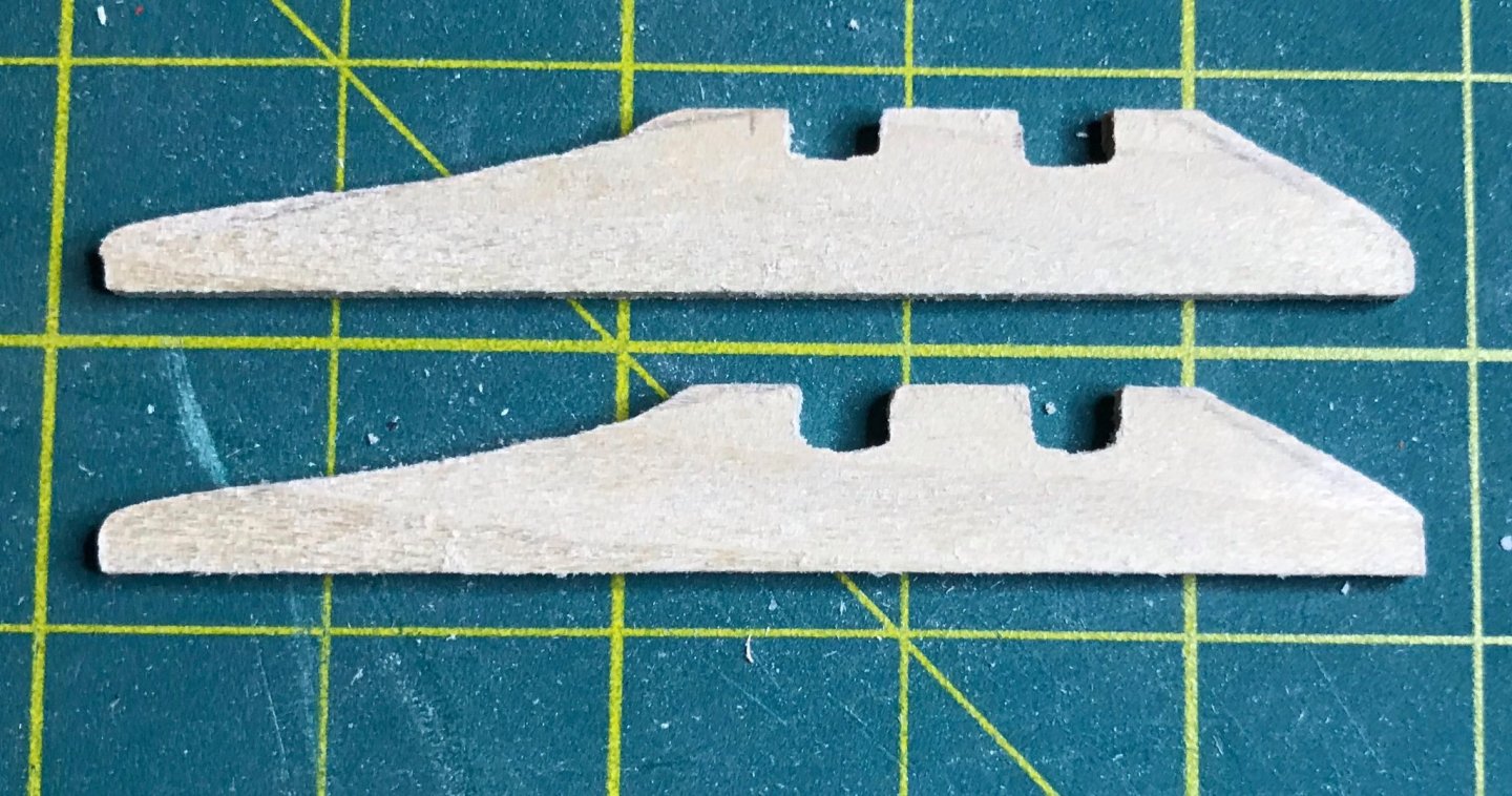
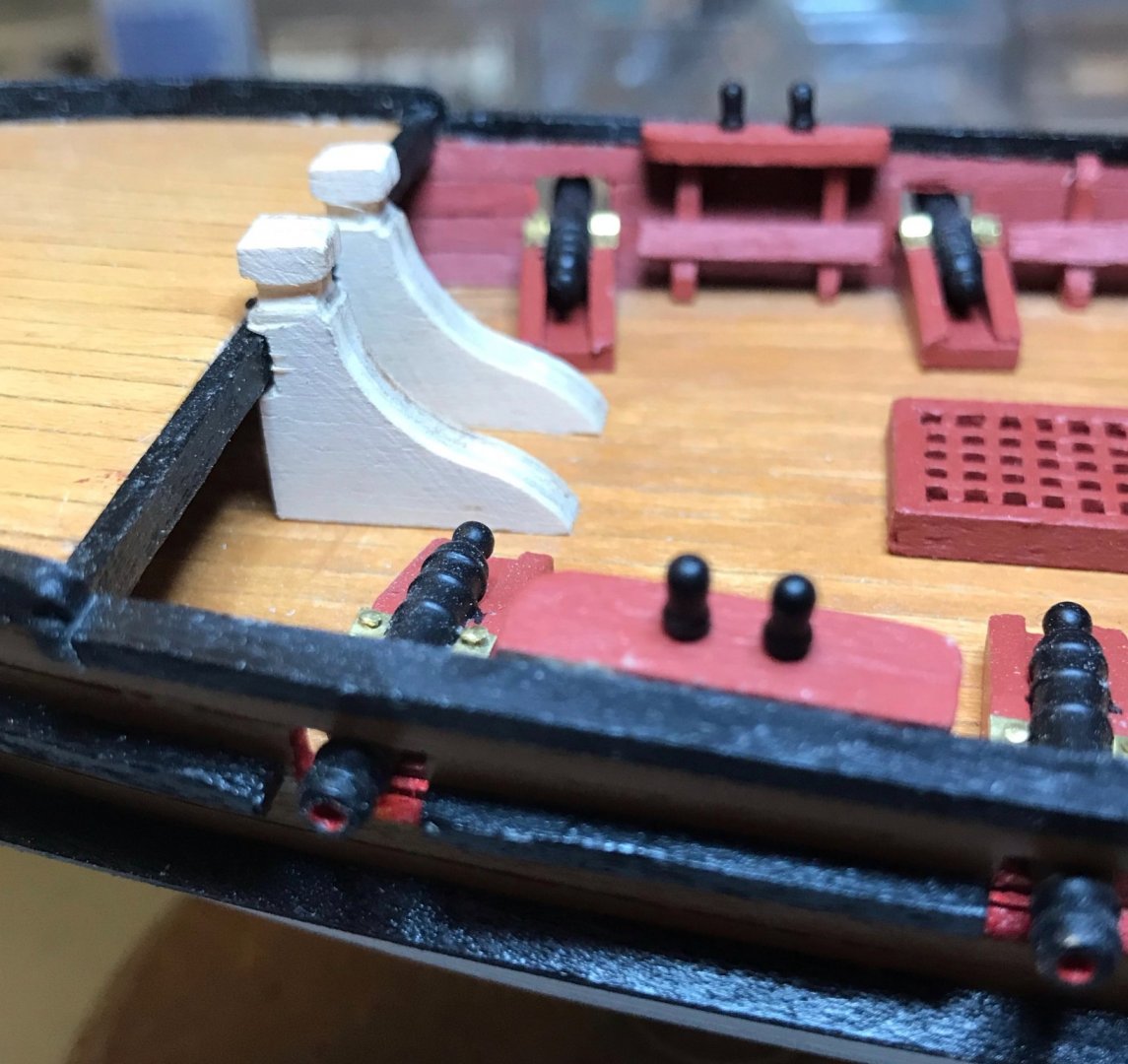
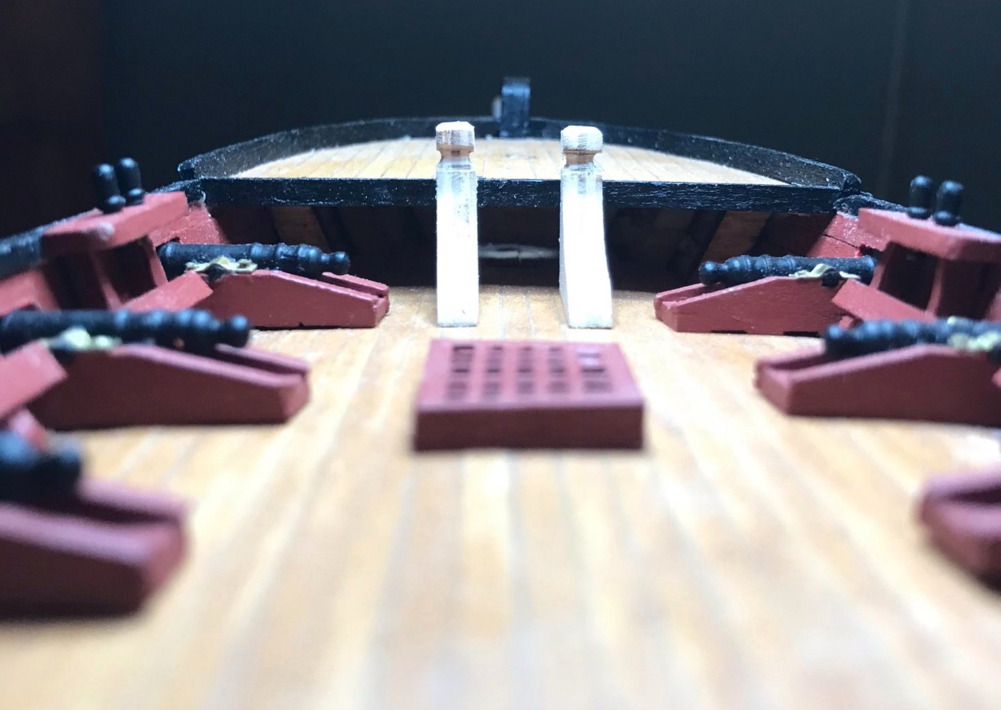
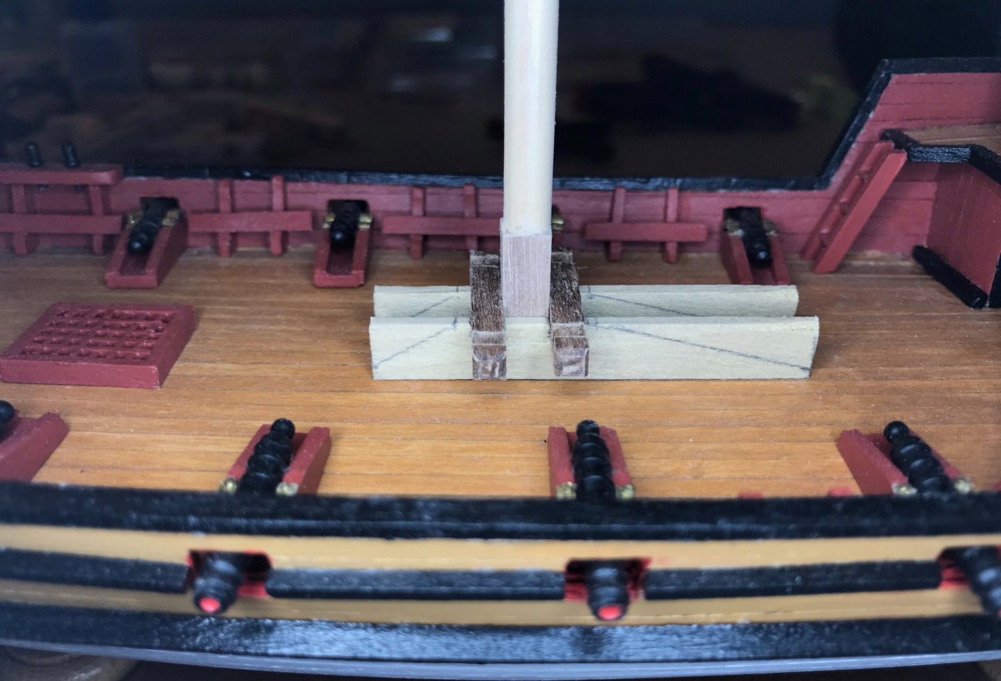
This week, I've been working on the remaining deck fittings for the maindeck—save the strips of eyebolts, which I'm going to do after the rest of the deck fittings are done. There are several units involved here: the mainmast, masthead, mast partners, mainmast bitts, and two supports at the forward end of the maindeck. And, of course, the antenne, though I'm going to wait to do those until I'm ready to work on the rigging. The various pieces are shown below. I decided to start with the forward supports, which have bitts at the top of them. These are the last of the pre-cut pieces that come with the kit. They just needed to be sanded down (from 5mm thick to 4mm). Then I added some beveling to the top of the bitt and rounded its throat. I also added some notches into the forward edge that will lap the after edge of the foredeck (which you can see in the first of the dry-fitting photos). Next up was the square bottom for the mast. I didn't take any photos, but I just used the same process as I did for the mizzenmast. Then on to the mast partners and mainmast bitts. The bitts are made of 4x4 walnut, with beveled ends and a rounded throat for the rigging (1st photo). A bit of inconsistency here, but it should look alright once the ropes are attached to them. The partners are made from 2x8 limewood and were the most complicated to shape (2nd and 3rd photos). While the measurements were given in the plans, I needed some fussy work with a file and sanding stick to get everything to fit just right. Although I drew the forward and aft angles as straight lines, I added a little bit of curve and rounded the ends while sanding. Finally, some dry-fitting (last three photos...taken before I had finished shaping the mast partners). Things are a bit crooked in the photos, but I'll get that straightened out once I glue everything together. For now, I was just worried about getting everything to sit flush on the deck and getting the mast to fit snugly between the partners and bitts. After taking these photos, I tapered the mast and assembled the masthead, using the same process as I did for the mizzenmast. Next steps: painting, attaching the masthead, and installing the maindeck fittings. I'll post photos once that's done. Then, on to the foredeck!


- 79 replies
-
- 2
-
-
- sergal
- sciabecco francese
- (and 1 more)
-
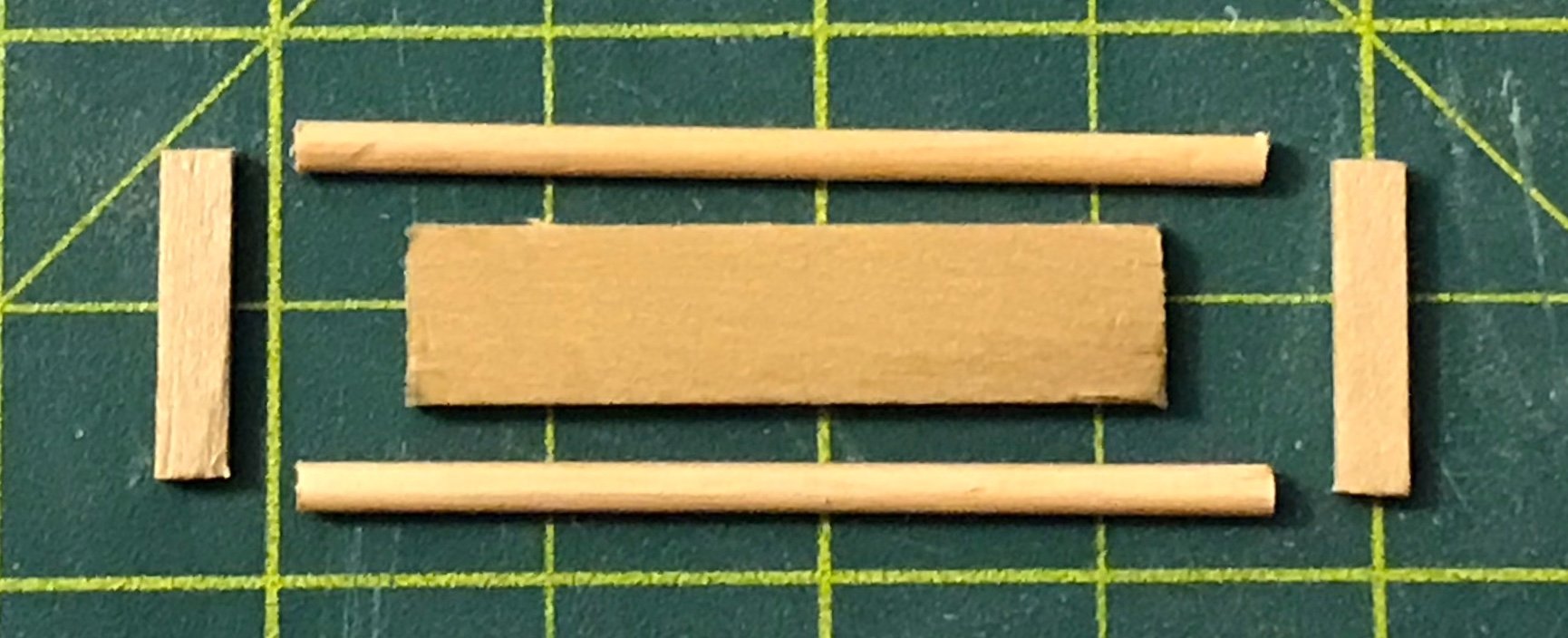
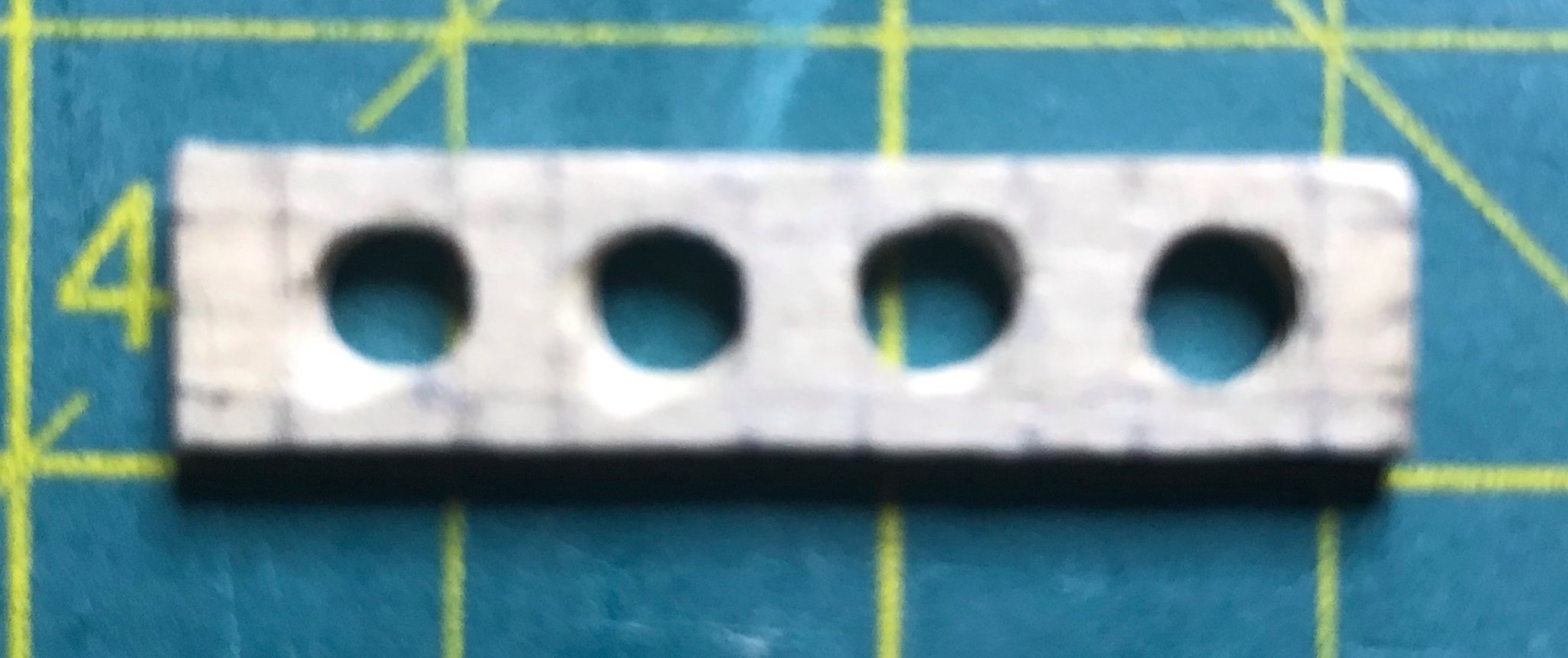
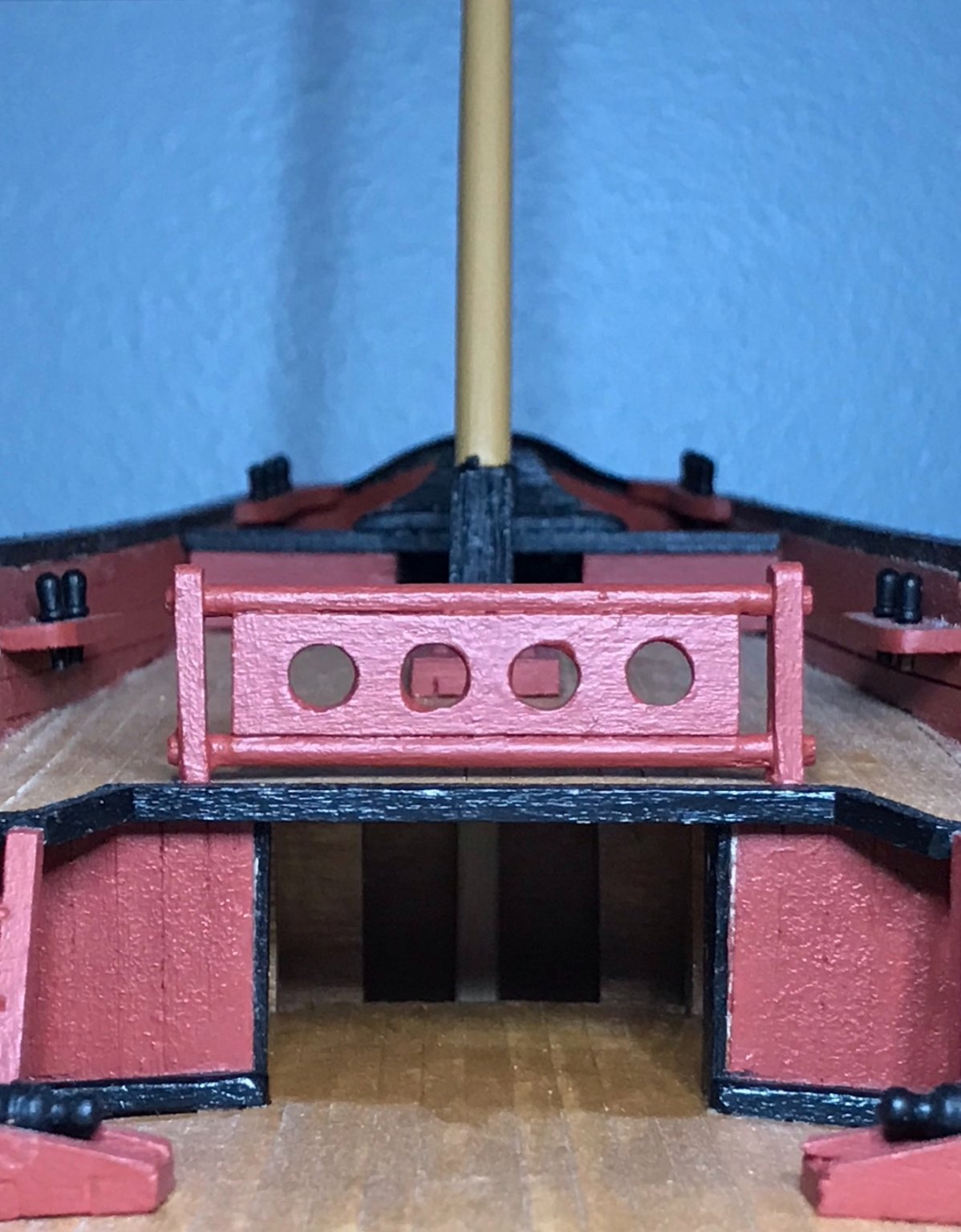
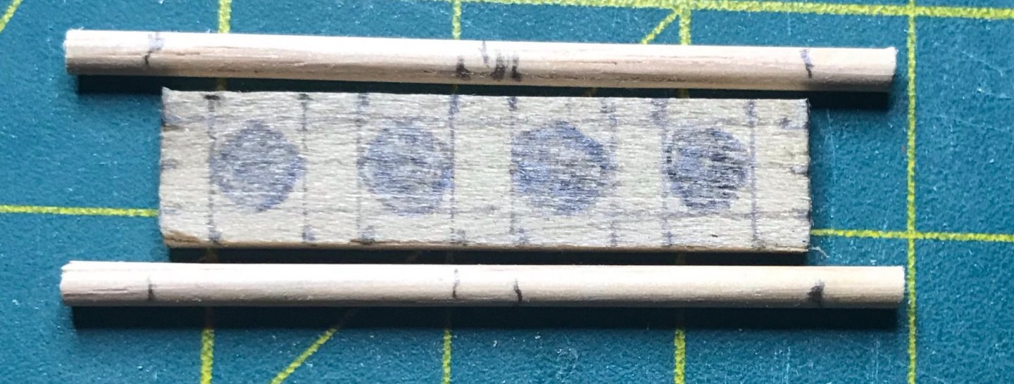
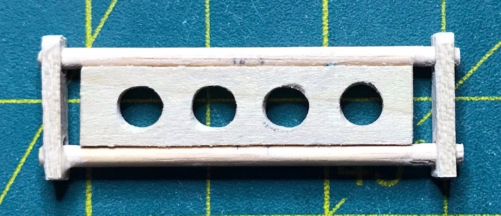
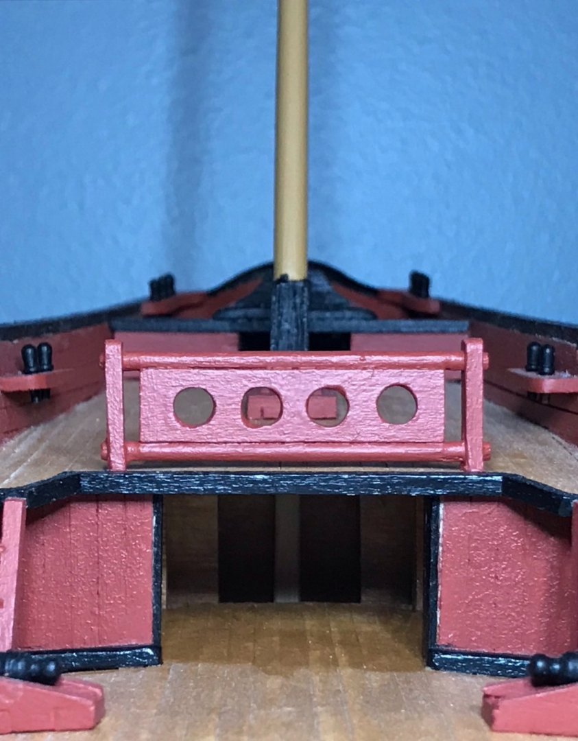
So, in my last post I said that I was done with the aftdeck, except for the strips of eyebolts. Oops. I had forgotten about the balustrade! Over the last several days, I've been working on that. I started by cutting out the five necessary pieces: a main block, top and bottom rails, and side supports (first picture). Then, I measured and marked up the main block and rails (second picture). I started by marking the lines on the main block: vertical lines every 3 and 5mm, alternating. Then horizontal lines across and 2.5mm on either side of the center. After that, I freehand drew the circles and shaded them in. For the rails, I started by marking the lines 1.5mm on either side of the center, then lined those up with the main block and marked the ends of the block. The next challenge was cutting the holes out of the main block. I used the router tip on my Dremel for this. After a bit of sanding, I snapped the photo (too early!) and then went back with a round file to improve the shape of the holes. Next, I sanded a flat side into the rails, sanding only between the lines that I had marked for the ends of the main block. And then came the real problem. I measured out the position of the rails on the side supports. Unfortunately, I have a hard time keeping my pin vice drill in place when I'm drilling holes with larger bits (a 2mm bit in this case). So, when I tried dry-fitting the rails into the side supports, I discovered that the holes were off. I also discovered that my 2mm dowel was generously sized and wouldn't fit into the 2mm holes. So I grabbed my round file and very patiently expanded and extended the holes. I also tapered the ends of the rails until they fit. In the end, it came together pretty well (second photo), though I'll be hiding the left side when I display the ship If you look very carefully at the left support, on the topside of the bottom rail, you'll notice that hole is so big it's even visible from this angle. After a bit more sanding and rounding off the tops of the side supports, the balustrade was ready for painting and installation. (Side note, in this photo you can really tell that I've applied finish inside the cabin, but not yet to the rest of the decks!) Now, I really am ready to start working on the mainmast assembly. I'll get to that once I clean and reorganize my workspace...things have really gotten out of control with two projects going on! (The other project was building a Pinewood Derby car with my son. The races were today and he got fastest in his den and 5th overall in the pack!)


- 79 replies
-
- 1
-
-
- sergal
- sciabecco francese
- (and 1 more)