HOLIDAY DONATION DRIVE - SUPPORT MSW - DO YOUR PART TO KEEP THIS GREAT FORUM GOING! (Only 20 donations so far - C'mon guys!)
×


HakeZou
-
Posts
325 -
Joined
-
Last visited
Content Type
Profiles
Forums
Gallery
Events
Everything posted by HakeZou
-
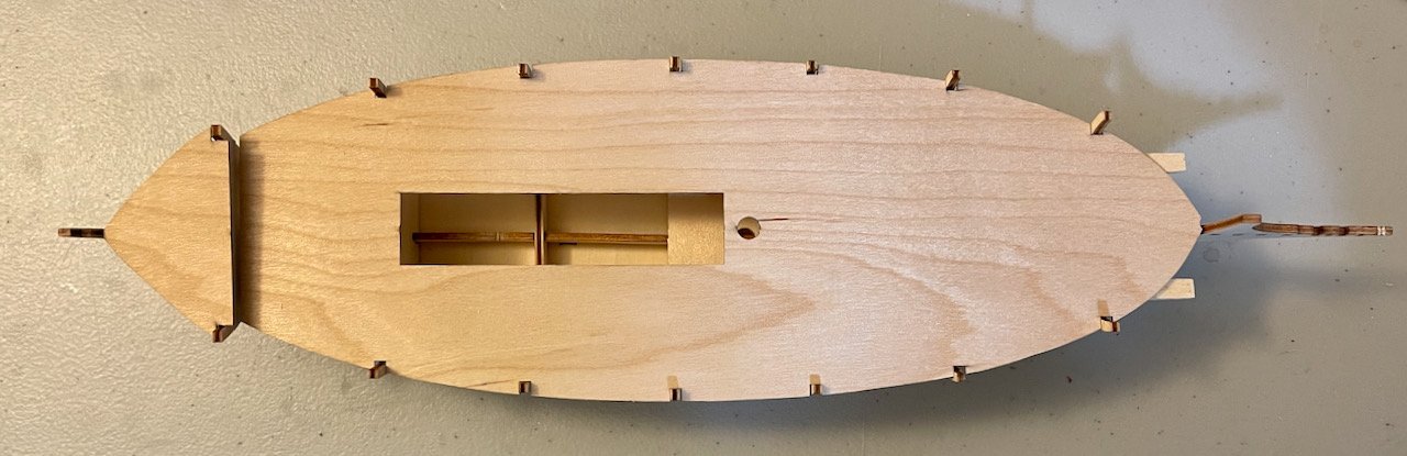
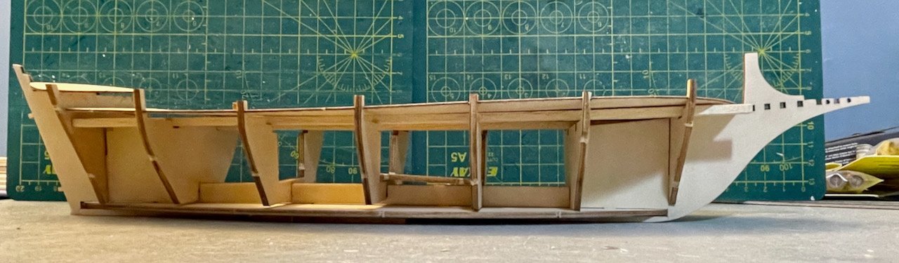
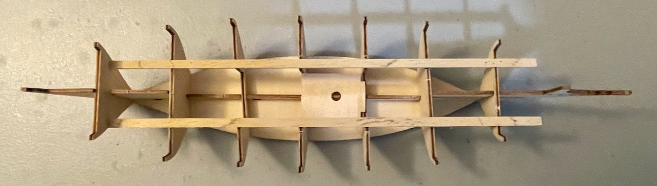
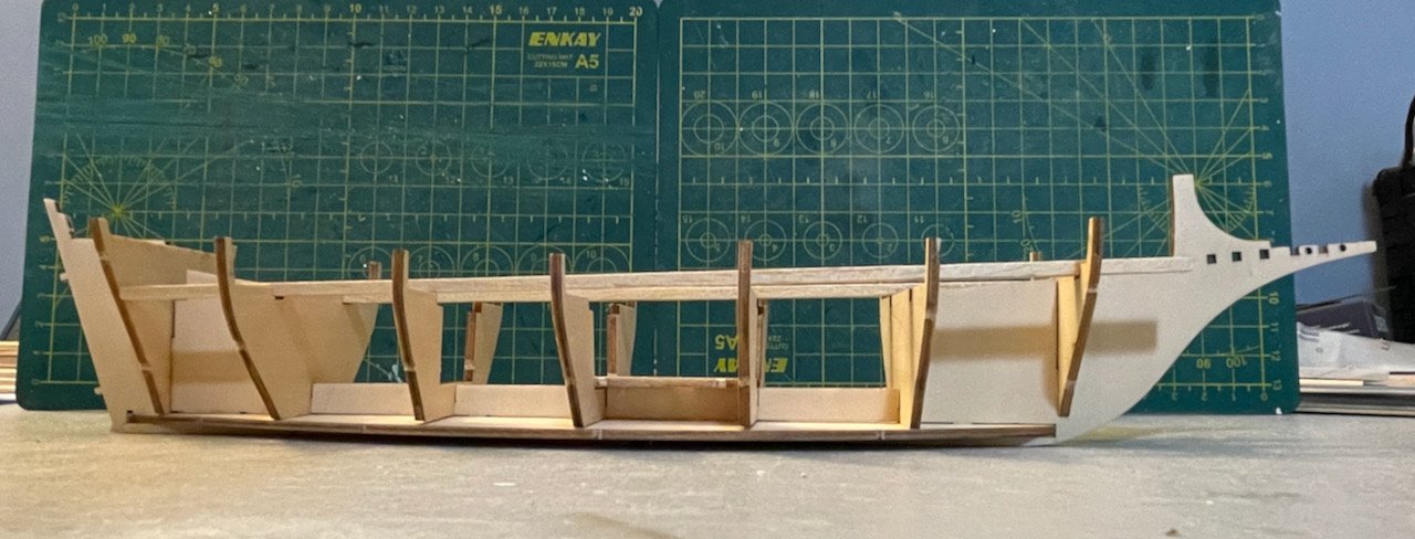
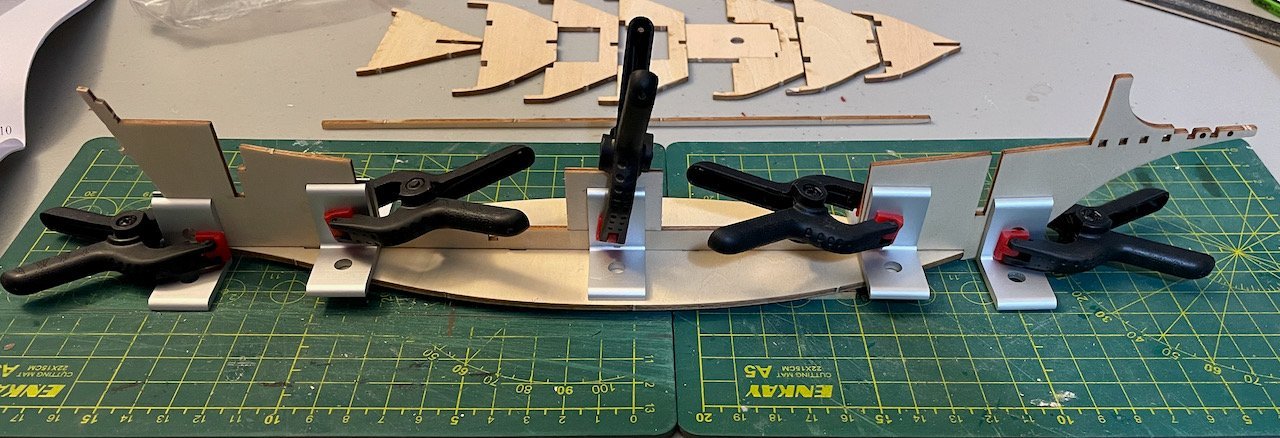
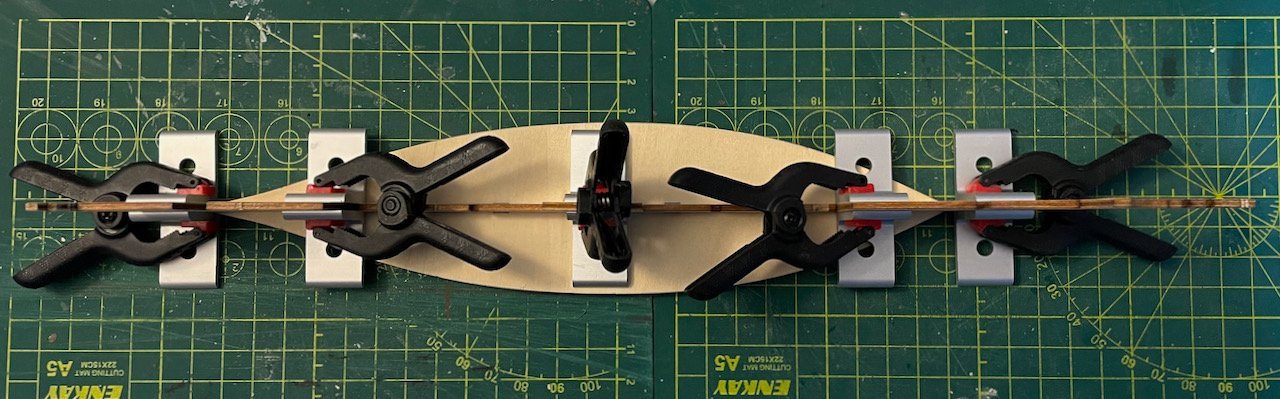
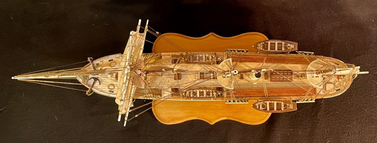
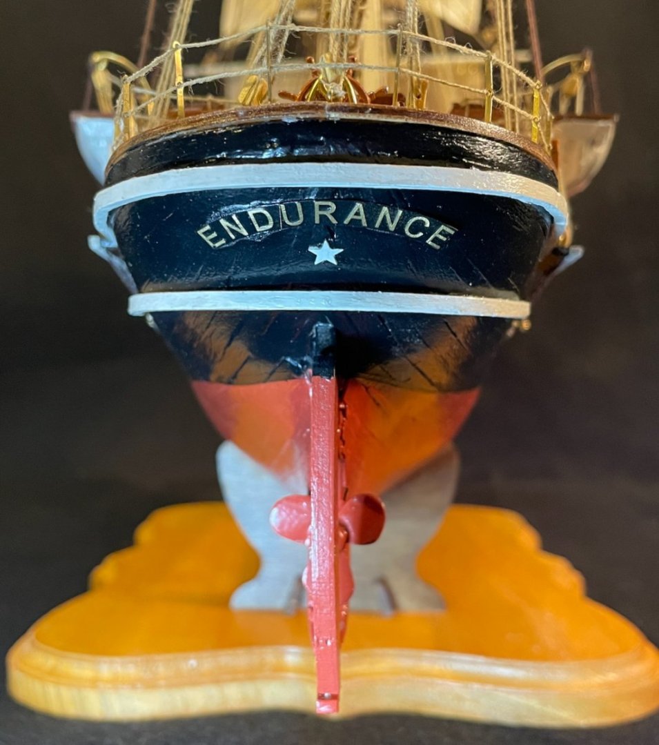
Hi, Bob and Keith! Great to see you again! Bob, one of the features that really drew my eye to this kit is the stern, which is built up in an interesting way (you can see this best in the second image of my opening post). I'm not sure yet what the functional reason for that design is, but I'm sure I'll figure that out along the way. Keith, I think that's a fair assessment of this set of instructions. For somebody who's new to ship modeling, though, a resource like MSW or Frank Mastini's Ship Modeling Simplified will be invaluable to learn strategies for installing the frames, planking the hull, etc. But it's not an overly complex build, so I think it should still be reasonably accessible for a first-timer. Last night I cut out all of the pieces through the decks, so I could dry-fit everything and see how it goes together. The two support pieces that run along the tops of the frames aren't cut evenly, so one of them fits beautifully and the other will need to be sanded down. The mast foot goes in nicely and helps hold frames #3 and 4 straight. The warping of the main deck is going to be a hassle, so that went back between boxes as soon as I was done with dry-fitting. The aftdeck and frame #7 are going to take some care to be aligned well; I saw Ben87 ran into a problem with this in his build, too. Here are some profile and overhead shots, with and without the deck. The fit of the frames is a little loose, so they look pretty wonky here; nothing to worry about yet, though. This morning, I installed the flat bottom onto the spine. I used clamps and brackets to ensure a square fit. (The brackets on the ends are just there so it will stand up.) I was hoping to put the keel on at the same time, but it wasn't cooperating very well. Once the glue for the bottom is dry, I'll work that out. Next steps: install the keel; prepare and install the frames.
- 59 replies
-
- 4
-

-
- Billing Boats
- Le Martegaou
- (and 1 more)
-
Hi Ben, I've just started building this kit, too. Now that I'm getting going, I can envision a lot of places that might be frustrating for a first-time builder. I hope that the very limited instructions didn't derail you too much and that you're either finished or still working! I'd love to see wherever you're at with it. Best, Hake
- 8 replies
-
- 1
-
-
- Le Martegaou
- billing boats
- (and 1 more)
-
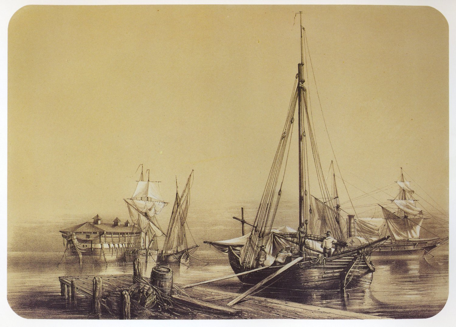
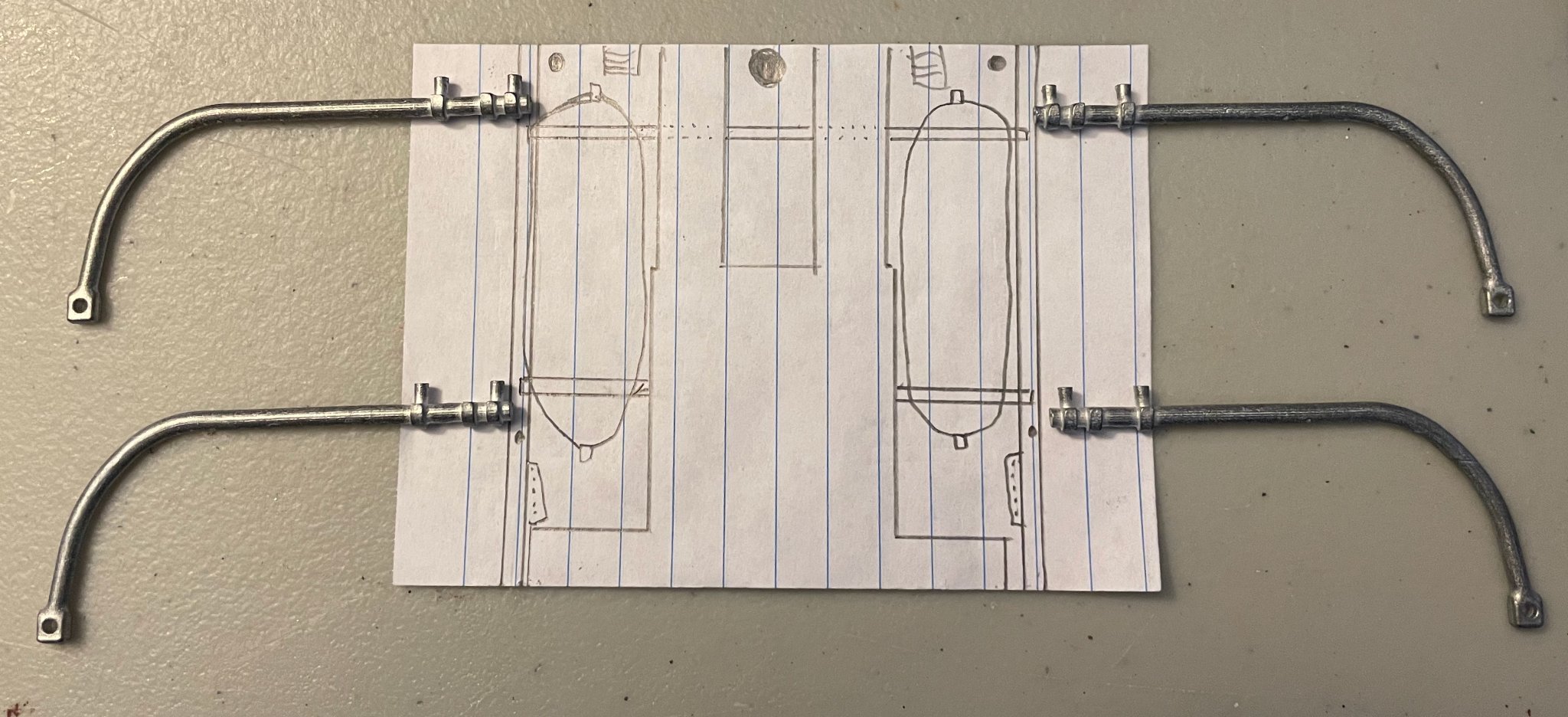
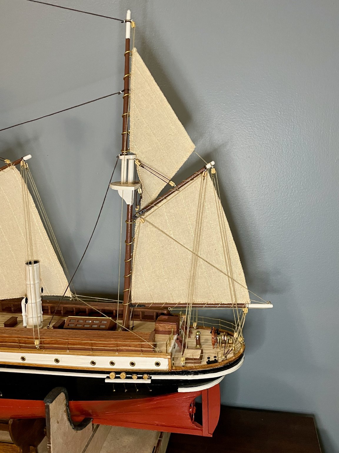
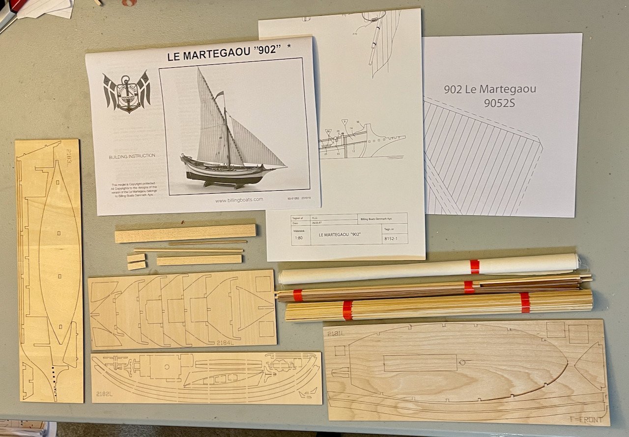
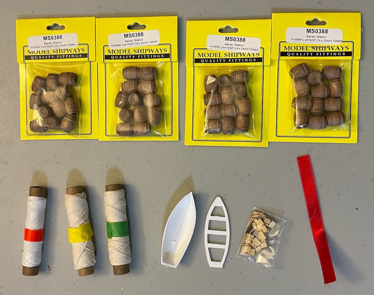
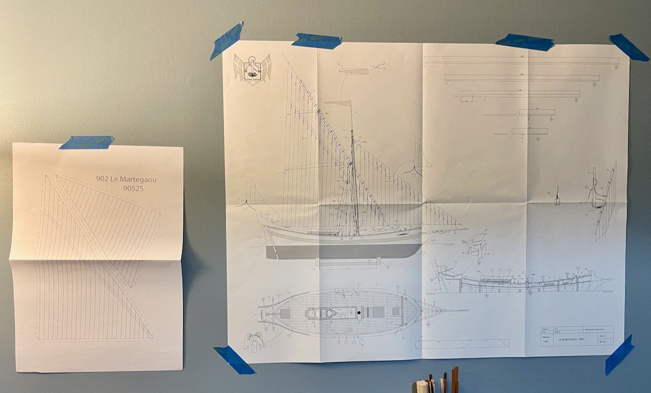
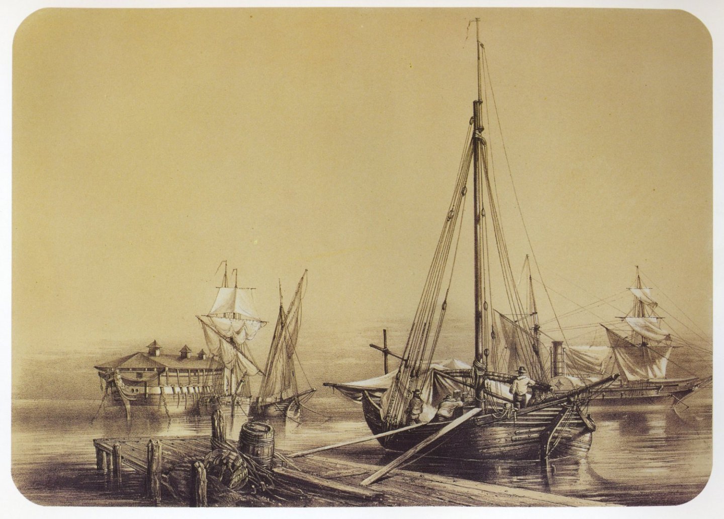
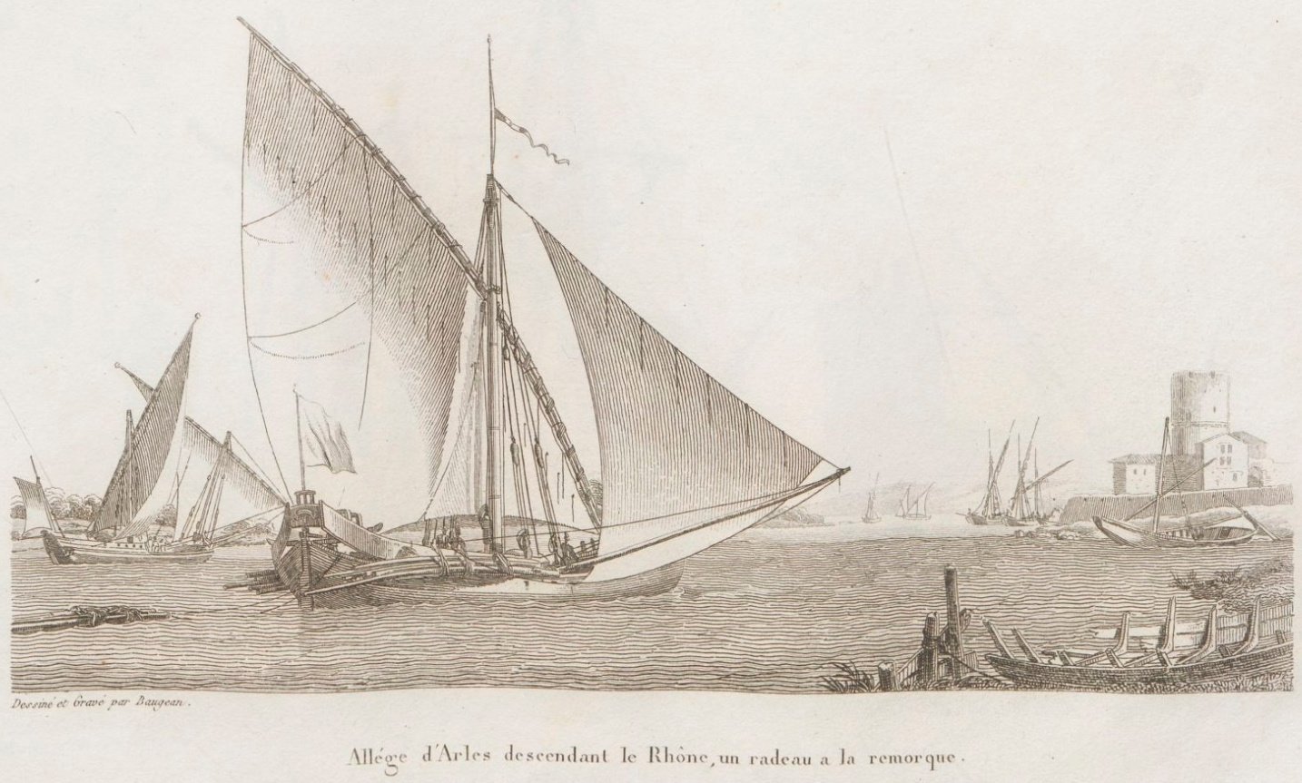
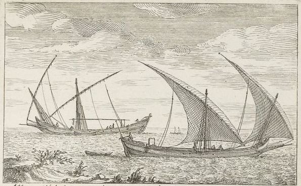
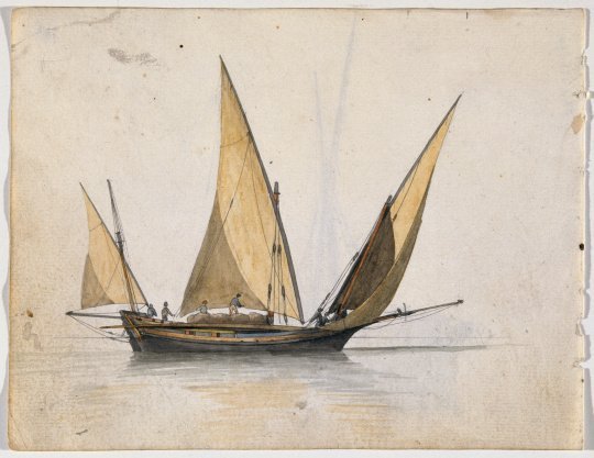
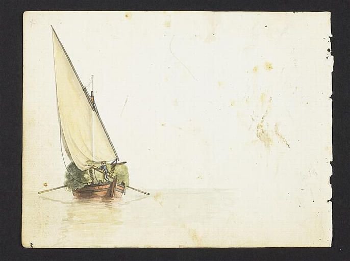
I didn't mean to jump into this build so quickly after finishing my Endurance, but today was one of those dismal grey days on which it's nice to slip into the basement and sit at my worktable. The kit arrived a few months ago, so I had already unpacked and inspected everything. But it was good to come back and check everything again while I got myself sorted and organized. Billing's description states: "A flat-bottomed boat from Provence. Vessels of this type were commonly used along the Rhone River for transporting building timber, tiles from Arles and fodder. The runs were eventually extended to include the southern coasts of France. The boats disappeared, however, as railway transport became widespread." This is a bit too simple for a historian like me, so I've been doing some preparatory research. The kit is of a fictional boat based on the tartanes and allèges that ran freight on the lower Rhone River, then along the coast in both directions as far as Sète in the west and Toulon in the east. (Coincidentally, two of my favorite places in France are Montpellier and Hyères, which are very close to Sète and Toulon, respectively.) The "allège d'Arles" is a celebrated boat in the Bouches-du-Rhône, particularly noted for hauling local tiles from Arles. While Billing comments that these ships were superseded by railway transport, steam-powered barges were the more direct culprit for the decline of these ships. However, the tartanes and allèges were part of a centuries-long development of sail-powered freight ships designed for the specific challenges of the Rhone River. Their flat bottoms, in particular, were essential for navigating through the shallow stretches of the river. Here are a few images that I'm using for inspiration. The first is entitled "Allège en chargeant dans le port de Toulon" (Allège loading cargo in the port of Toulon). The second is a woodcut by Jean-Jérôme Baugéan and the title translates to "An allège from Arles descending the Rhone River." The third is a much earlier woodcut by Pierre-Jacob Gueroult du Pas entitled "Allège d'Arles, pour le transport de bois" (Allège from Arles, for transporting wood). Finally, there are two paintings by Antoine Roux of allèges d'Arles. The kit comes with the usual variety of planks and plywood. The three thicker pieces of plywood seem to be of decent quality, though the laser-cutting left a lot of marks on the backside. The thinner piece (lower right with the main deck piece dominating) looks like single-ply plywood; it's very thin and badly warped. I have it sitting between two boxes in hops that it will flatten out. If not, maybe an iron on low heat will help? In addition to dowels, the planks are made of poplar and obeche. There's also a roll of sailcloth, which means I'll be making my own sails for the first time. The instructions—available for free on Billing's site, which I appreciated when I was trying to decide what to build next—are what I've come to expect from most kits. The text instructions are very limited and assume prior experience building model ships (a note to any raw beginners: don't be scared off; MSW provides a great knowledge base for figuring out what the instructions aren't telling you!). The photos in the instructions are in black-and-white and of just okay quality. The diagrams are a single large sheet, accompanied by a single sheet with templates for the sails. Per my usual approach, I've hung the plans on the wall above my worktable. In addition to the wood and sailcloth, there's a small plastic package with rigging thread, hardware, a ribbon (for a pennant on the mast), and the lifeboat. The rigging thread seems to be in three diameters, though I'll need to take a closer look to be sure; it's also much better quality and more rope-like than I've worked with on any of my prior kits. The lifeboat is plastic and comes in two pieces; I do not plan to use it. The hardware looks like it's all decent quality and is definitely usable. In addition, you'll notice I picked up four dozen barrels from ModelExpo/Model Shipways. My plans for the kit are: This kit is primarily about improving my skills. I'm particularly looking to get better at planking both the hull and the deck. I'm hoping to go without paint for the first time. I'm hoping that the wood will look good enough that I just need satin varnish, though I'm also fine with using wood stains if I need. After my experience with the Endurance, I'll probably do a little bit of kitbashing and upgrading. For example, I'm going to build this as a fully loaded freight vessel, hauling a load of wine. (Coincidentally, a couple years ago, I gave my wife an artistic map of the Rhone Valley wine regions, along with some sample bottles...there's definitely some inspiration there.) Rather than placing the lifeboat and its cradles over the cargo hatch, I'll leave it open and fill the hold with the wine barrels. This will also mean planking the lower deck. My goal is something that looks a bit like the first Roux painting above...though I'm not sure yet if I'm ambitious enough to add the other two masts from the painting. I notice that Ben87 started a buildlog for this kit last year and that RDDP mentioned they are working on this, too. Hopefully, we'll have a nice little community as we work on this together! Next steps: prepare and assemble the spine, flat bottom, and keel pieces.
- 59 replies
-
- 6
-
-
- Billing Boats
- Le Martegaou
- (and 1 more)
-
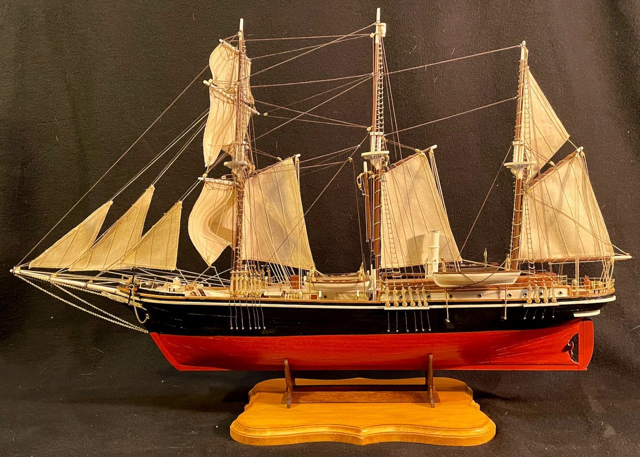
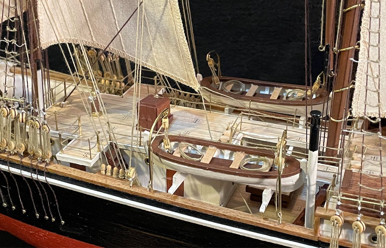
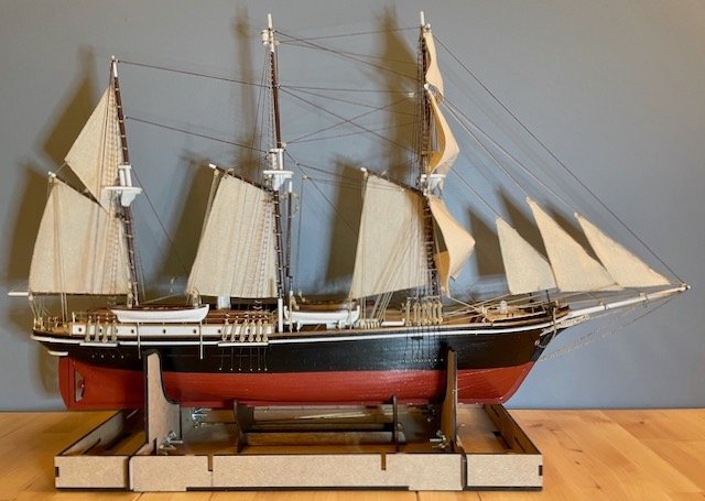
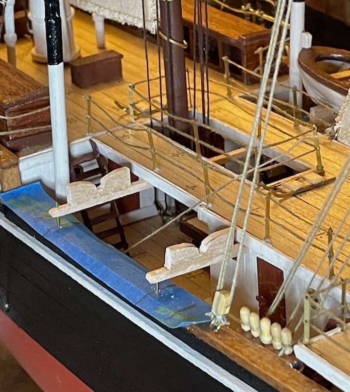
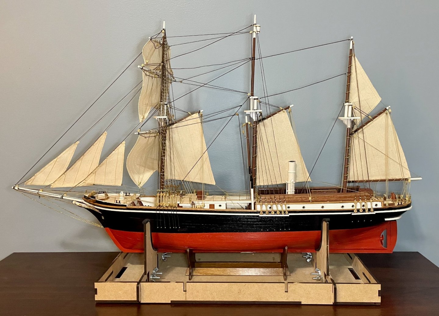
Thanks for your kind comments, everybody! The big challenge now is finding a place to display this model, since it's too big for any of my bookcases! I already have Billing's Le Martegaou sitting on my shelf, patiently waiting for me. It's a much simpler project than the Endurance, but one that I'm going to use to hone some of my skills. The ship is based on the early nineteenth-century tartanes and allèges that were used to haul freight in the stretch of the Rhone River below Arles and along the Mediterranean coast. I completely agree with you, Johnny. Straight out of the box, it will definitely make a good model; most of my model is just that. But the possibilities for upgrades, refinements, and kitbashing are endless! I should add that the deck fittings are not all that accurate, which offer another good opportunity for improvements. The dog kennels and gear boxes are very simplified, and there were more kennels (including on the bridge deck!). The hatch on top of the Ritz should be a skylight (the hatch provided in the kit properly belongs on the quarterdeck). It would be cool to see somebody make the kit with windscreens on the bridgedeck railings. I also noticed, much too late, that the forward bulwark on the maindeck was open between the stairs. If somebody wanted to show more of the expedition's gear or to make a diorama set in the Weddell Sea, Frank Hurley's photos can provide a ton of inspiration for detail—for example, how cool would this look as a diorama?! All this to say, ultimately, that with this particular community, I wouldn't be surprised to see a dozen buildlogs showing a dozen different versions of this kit! OcCre has designed a kit that makes a lot of things possible—and they've provided the supplies to do much of it.
-
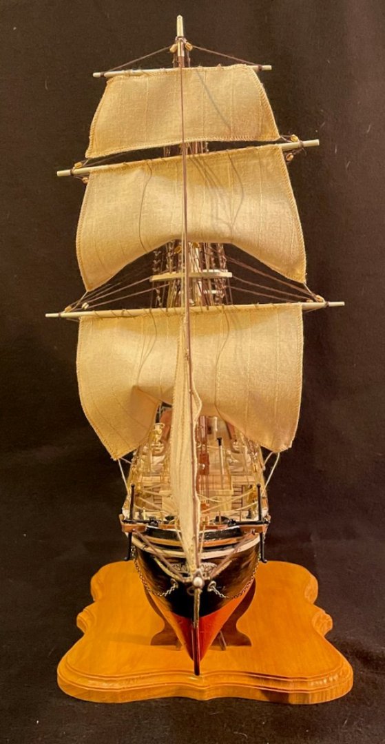
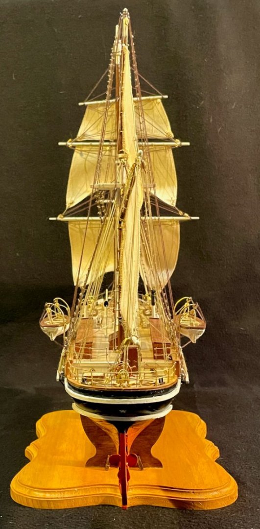
Today, I'm declaring my Endurance finished! First a few thoughts and then the glamor shots. Overall, this was a tremendously enjoyable project and one that I think is well worth the time and money that will go into anybody's build. I wouldn't recommend this for a raw beginner, but for somebody who's done a few kits, this is accessible and will provide numerous opportunities to improve your skills. A builder like that will definitely be capable of making a model that will make them proud. For those (like me) who've only built fishing boats, this kit is a good introduction to tall ships with square sails. For an experienced builder, the opportunities for kitbashing and other improvements to OcCre's designs are plentiful (be sure to follow Clearway's buildlog for some inspiration). OcCre's hardware is mostly of pretty good quality. They are also quite generous with the hardware and building materials—you can make a lot of mistakes along the way, experiment, and build upgrades. The only exceptions are that there are not enough two-sheave blocks and I ended up buying more 1mm brass wire. This was my first OcCre kit, but it won't be my last. They've done a great job designing a kit that should be of interest to a wide range of builders. The photo instructions are clear and the rigging plans (despite my quibbles with some of the details) are the best I've encountered yet. This was a really big step up for me skill-wise, but I'm really happy with how this turned out! For others building the kit, a few suggestions: Devote plenty of time to studying the rigging plans and working out how all of the ropes run. As I noted a few months ago, I think the rigging plans have some mistakes and some places where the paths of certain ropes don't make sense. I disagree with the recommended order (though I'm not sure my order was all that much better in the end). My rigging solutions are one option, but spend some time with the model in your hands to find your best solution. The best upgrade you can make to the kit—which I didn't do—is to replace the kit's railings. 3-D stanchions and brass wire will look a lot better and be more stable than the flat stanchions and thread that OcCre recommends. The second best upgrade would be the lifeboat davits. I fashioned my own, but there are probably some available in stores that would be closer to the ship's scale. The third best, which I also didn't do, is to replace the smokestack and reposition the air intakes (which do not match the original ship). There are also lots of opportunities here to add small details that aren't in the kit's plans. Frank Hurley's photos are readily available online and offer tons of details for inspiration. Hurley's archival collection is at the National Library of Australia, but you can also access many of his photos via Getty Images. Finally, the photos you've been waiting for. Apologies in advance for all of the dog hair, which is ubiquitous in my house even though she almost never comes down to the basement! Thanks to all who followed along and, especially, to those who offered encouragement, advice, and tips along the way!

- 173 replies
-
- 16
-
-

-

-
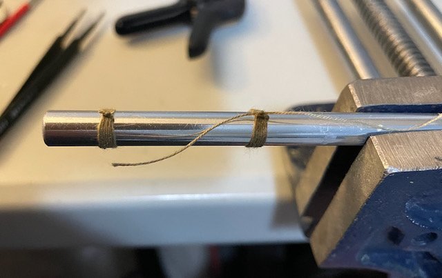
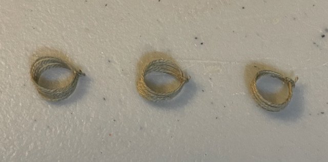
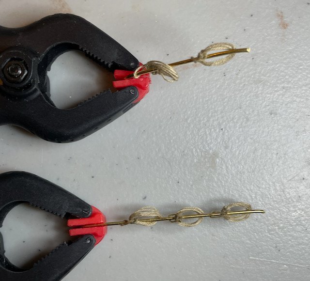
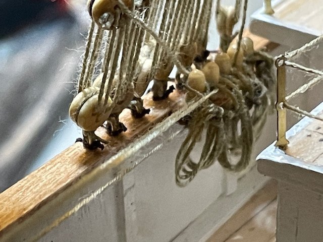
I've been working on my finishing touches. After studying the photos of the Endurance on Getty Images, I've settled on rope hanks for the belaying pins, some rope coils, the portable davit and its pedestal (from quite a few posts ago), capstan bars and a stowage box, and a smokestack for the stove in the galley. The last three needed to be fabricated, but I'm nearly done with them. I've also made 15 of the 26 rope hanks. On previous models, I've struggled to make good rope hanks. After reviewing the relevant section of Frank Mastini's book and a few YouTube videos (especially Tom Lauria's excellent tutorial), I can confidently saying I'm getting better. Still plenty of room for improvement, but that's why I've started with the ones that are least visible. Here's the method I've settled on: The first step draws on Mastini's advice. I took my Exacto knife apart and placed the handle in a vice grip. Then, I tied a common whipping knot finished with a square knot, applied a drop of Dritz FrayCheck, and trimmed the loose ends. In the photo, you can see two hanks in progress, one with the loose ends already trimmed. Next, I slid the coils off the Exacto handle. Following Lauria's advice, I used angled tweezers to wrap the backmost loop twice around the other loops. Then, I shaped them on brass wire. As I slid the wire through I gave the single loop a half twist. I pinched and stretched the hank to give it a more elongated shape. In the second photo, the hank in the upper left is rotated on the brass wire to show the angle at which the small loop is being set. Once I was satisfied with the shape, I added a drop of FrayCheck to the spot where the small loop wrapped around the others. Finally, I hung the hanks on the belaying pins. This was by far the most challenging part of the task, since I had to maneuver my tweezers around the bridge deck, railings, bulwarks, shrouds, and all of the foremast and staysail rigging. The hanks kept flipping up, though, so I ended up applying some more FrayCheck and used a plank to hold the hanks back while the FrayCheck dried. I think I did an okay job, but am looking forward to doing the rope hanks at the forward end of the foredeck—they should be much easier to hang! (Apologies for the awkward camera angle...given the location, it was the best I could find.)
-
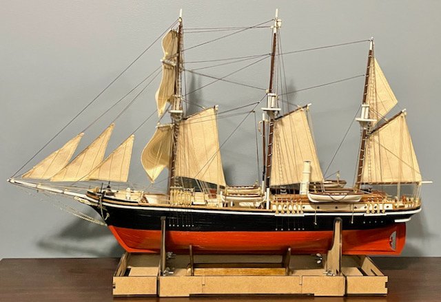
Keith, I hope that your weather hasn't been too bad! We were fortunate to have only a moderate snowfall here. Friends elsewhere in the Midwest, though, really got dumped on! Good weather for working in the basement, which led to me really getting on a roll this evening. The port side—the main display side— is finished now, too! Since the rigging is so much more complicated on this kit than my previous ones, I've been tracking my progress there in a spreadsheet (the same one I used to figure out the paths of some of the ropes!). The final count was 210 pieces of rigging and 276 ratlines. Those numbers have been daunting for quite a while, but now are giving me a huge sense of satisfaction. Here's a profile shot: In addition to finishing up the ratlines tonight, I installed the portside lifeboat davits and hung the lifeboats. Here are a couple detail shots of them. The midship. I'm really pleased with how the midship one turned out. The quarterdeck one is pretty good, but I wish I'd managed to get that one davit straighter. I also added some pieces of the heavier thread to function as the straps that stabilized the quarterdeck lifeboats. Remaining steps: Add the final touches. In my next post, I'll show some of the wood and metal pieces I've fashioned to finish things off. In addition, I still need to make some rope hanks and coils. I'm also planning to pick up something I can use for a more sturdy display base; the stand that comes with the kit seems a bit flimsy for a model this size.
-
We were caught up in the big storm blowing across the Midwestern US, with school and work cancelled today. Apart from shoveling snow and walking the dog, I managed to spent a good portion of the day in the basement working on my Endurance. I finished off the starboard ratlines and hung the quarterdeck lifeboat on that side. And now, the starboard side is done! Remaining steps: main and mizzen upper ratlines on the portside, install portside lifeboats, add the final touches.
-
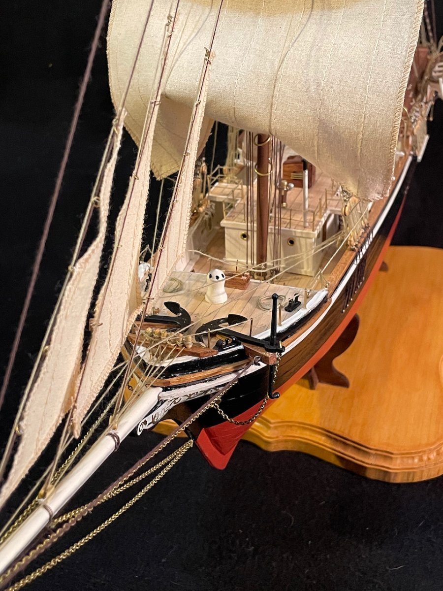
Wow, Bob! Your Pen Duick is looking really impressive! The work on the deck fittings looks really great. So glad to see that you are able to get back to this kit and to share your work with us!
-
Johnny, I had the same question and my initial guess was the same! After a bit of digging around on the internet, though, I found a better answer in the form of a British Pathé documentary showing a lifeboat drill on the RMS Aquitania. Both the Aquitania and the Endurance launched in 1914 and both use radial davit systems. (For those, like me, who know very little about davits, the key thing to know is that radial davits are operated manually and can be turned independently.) By turning one first and then the other, the lifeboat passes between the davits at an angle, allowing for a boat that is longer than the distance between the davits. It appears to be a job for four men, two in the boat and two at the bases of the davits; the men in the boats seem to be adjusting the pendant rope as needed to keep the boat level. On my model the midship davits are aligned as close as I could get to the spacing on the original ship, which really does allow the lifeboats to pass through at an angle. (I'll note here that the lifeboats with canoe-style sterns seem to be more-or-less in scale; the ones with transoms seem to me a bit oversized and out-of-scale. I don't have hard numbers on this, just a general sense of it.)
-
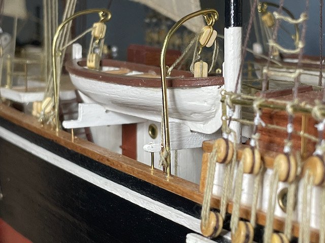
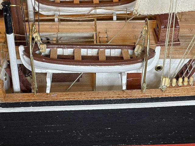
Some more slow progress over the last week and a half. I'm continuing to chip away at the ratlines—only 68 more to go! I've also been working out the details of the lifeboat davits. And, since I've finished the starboard upper ratlines on the mainmast, I decided I might as well install the midship lifeboat and davits on that side. The first photo is a full shot of the lifeboat, resting in its cradles, with the ropes tied off to the davits. Next, a couple detail shots to show my solution for the davits. While studying the photos of the Endurance (for example this one), I noticed that there was an eye or a channel or something that the rope passed through, allowing it to clear the lifeboat's gunwales. So for each davit, I popped a link off the chain that came in the kit. After rounding that link, I used CV glue to attach it to the davit. (Again...that lack of soldering skills. But a friend of mine who's a jeweler is going to teach me!) Since I'm out of eyebolts, I decided to try wrapping the blocks in wire, with a loop on each end. I'm getting better, but at this point it's a slow and often frustrating process for me...and the camera angle in the next photo isn't doing me any favors! Both photos show the forward davit, from opposite sides. You'll notice that the rope is tied off to the upper block, runs through both of them, then through the eye on the davit, then down to the cleat I showed in my last post. 1 lifeboat down, three to go. But first, I need to finish off another section of ratlines.
-
With the new semester dawning, work has really picked up for me. So, just a quick check-in. My checklist for the Endurance is growing even shorter now. I'm still working on the upper ratlines for the main and mizzen masts. I've also started painting the cradles for the midship lifeboats. Nothing interesting to show on those fronts, though. Today, I finished the last bit of crafting I needed to do—the davits for the midship lifeboats. These are made in a very similar fashion to how I did the davits for the quarterdeck lifeboats. The big difference is that these are mounted into the caprail. I'm toying with the possibility of adding a small ring around the base, but otherwise these are done and ready to install once the cradles are installed. (Since they aren't firmly in place, they aren't quite straight in the photo. They're also rotated outward, since they showed up better in the photo; once installed, I'm planning to turn them inward, over the lifeboats.) Remaining steps: finish the main and mizzen upper ratlines; finish painting the lifeboat cradles; install the cradles, lifeboats, and davits; add the finishing touches.
-
Thanks, Johnny! My rope railings look kind of wonky in several spots, I think because some of the stanchions have bent a bit out of position. As I finish up, I'll be going back to touch all of those up...hopefully the ropes will look better then! And I think you're right about soldering the brass being better. I neither the equipment nor the skills to solder anything, so am relying on CA glue as the next-best solution. I hope you'll do a build log once you start working on your Endurance. I look forward to seeing how you approach yours!
-
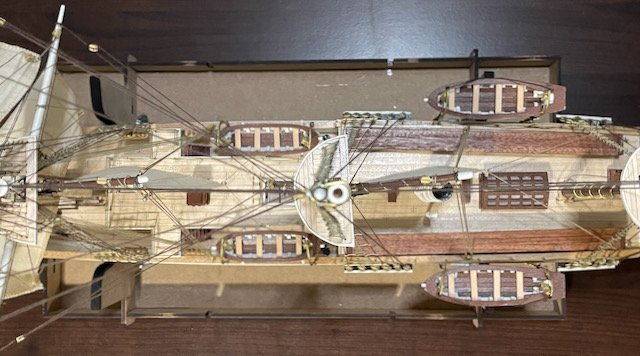
Thanks, Jeff! Last night I made the port side davits for the quarterdeck lifeboats. Today, I turned to the cradles for the midship lifeboats, since they are the most challenging problem that remains. The first step was to shape the cradles themselves. These are made of 2x5x18 basswood. There's a bit of inconsistency in the sanding/filing, but I don't think this is very noticeable once the lifeboats are in place. . Next, I attached the cradles to their support beams, which are made from 2x2 basswood. The after support beam runs all the way across the ship, under the catwalks, while the forward support beams attach to the sides of the Ritz. I rounded the ends of the support beams to match my observations from Hurley's photos (this one for example). Then a couple test fits to make sure I hadn't shortened the support beams too much when I was sanding—I was particularly concerned about the after one, so I took photos of that one. (You'll have to look closely in the second photo, which is an overhead shot from the top of the mainmast.) . Locating the postholes proved to be a challenge. I ended up laying strips of painter's tape on both caprails, with pre-measured markings for the davits and the support beam posts. The posts themselves are brass pins with the heads removed; I still need to trim some shorter, but they're all close enough for now. I also inserted brass pins into the ends of the forward support beams, to provide more strength where they attach to the Ritz. Finally, I took the opportunity to check the strength, fit, and overall impression with the lifeboats in the cradles. The structure is actually stronger than I expected! Even without glue, there's no issue at all with the lifeboats weighing down the cradles/support beams. (I won't glue these into place until the davits are ready to be installed.) Next steps: Install the ratlines on the main and mizzen upper shrouds; paint the lifeboat cradles; make the midship lifeboat davits.
-
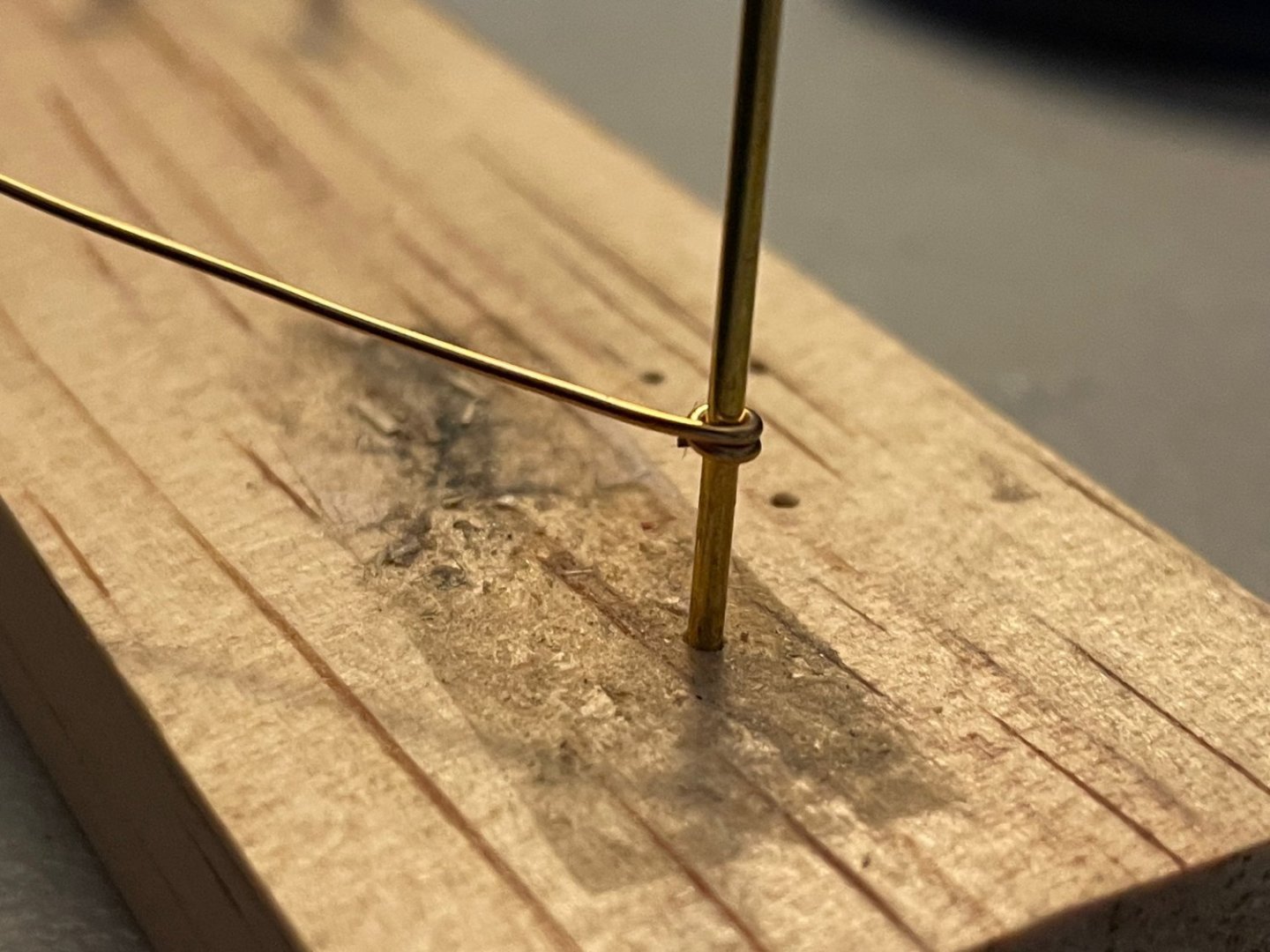
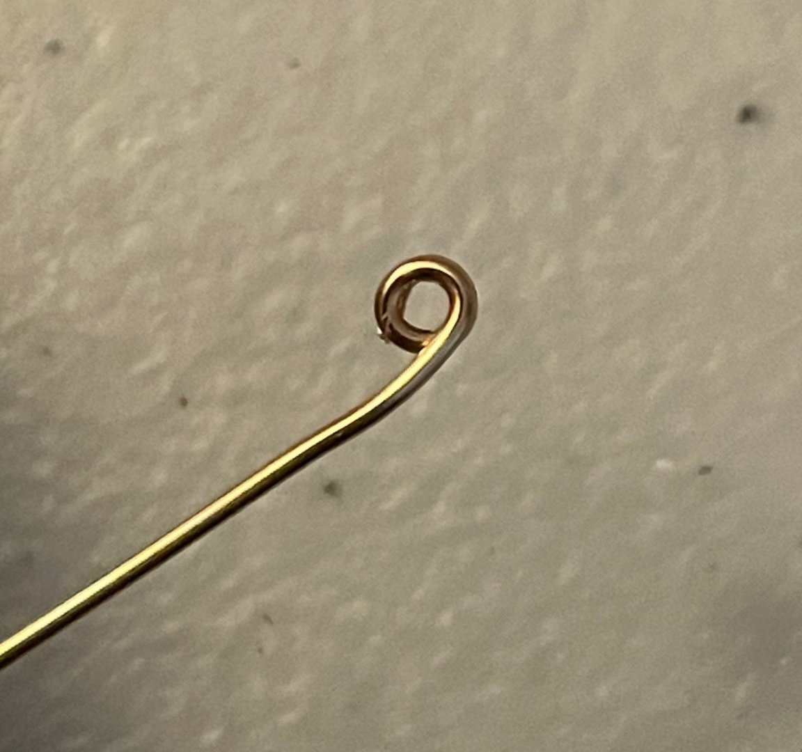
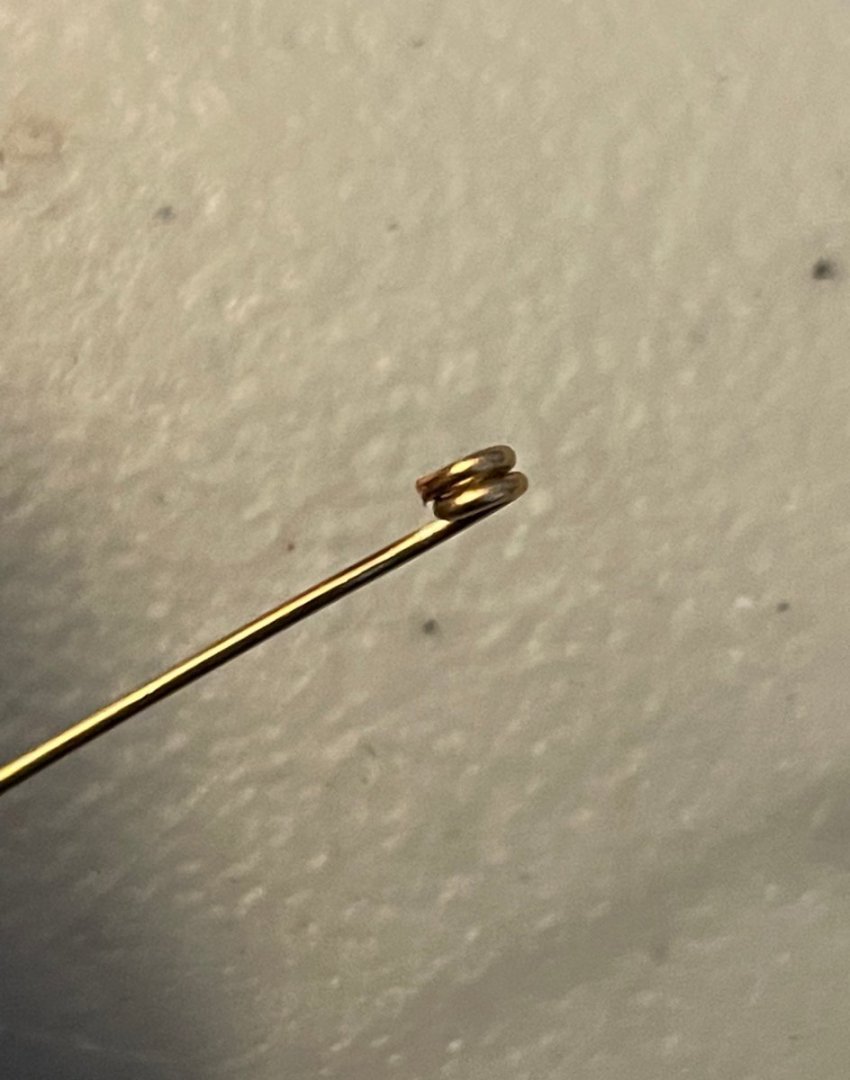
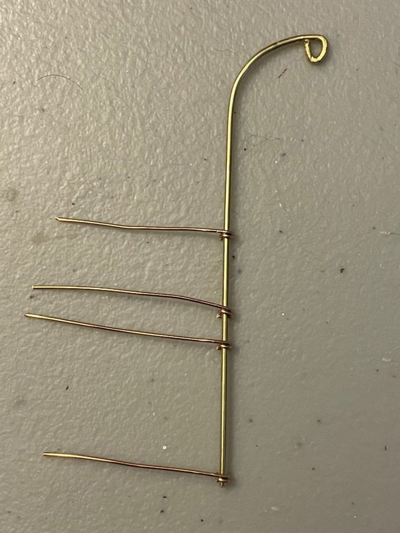
Happy new year, everybody! Thanks as always for following along. After a lovely holiday season, I'm back at work on my Endurance. I've finished up all of the ratlines on the main and mizzen lower shrouds. All that remains in terms of rigging are the ratlines on the main and mizzen upper shrouds. I've also been working on the davits for the quarterdeck lifeboats. The challenge this week has been figuring out how to attach them to the hull. As I have observed before, there are four attachment points on each davit, so I needed to figure out how to 1) fashion the posts and brackets, 2) fashion cleats, and 3) line everything up correctly on the hull. For the posts and brackets, I used some 18-gauge brass wire. After a bit of experimentation, I ended up using a jig...though that may be too generous of a term here. Since the davits are made of 1mm brass wire, I drilled a 1mm hole in a spare piece of wood, then inserted a spare piece of 1mm brass wire. It's nothing fancy and certainly isn't pretty, but it got the job done. I began by double-wrapping the 18-gauge wire around the jig, trimming the short end off and using needle nose pliers to tighten the wrap as much as I could. . After sliding the wire off the jig, I double-checked the shaping. . Next, I arranged four of these wire pieces on each davit. I carefully positioned the top and bottom ones 34.5mm apart and secured them in place with a dot of CA glue. The middle two were not glued into position. I left the posts long for now—I eventually needed to trim the top one, but the lower three all can go deep into the hull for a more secure fit. Next up was the cleat. I decided to make these out of two straight pieces of 18-gauge wire. The shorter piece is glued directly onto the davit, while the longer piece is glued onto the shorter piece. A bit of a blurry photo here, but you can see the two starboard-side davits resting in clamps and pointing opposite directions. The posts look pretty wild because the middle ones are just falling haphazardly. I still need to trim the ends of the cleat on one of these, since they're a bit too long. My final challenge was working out where to drill the eight post holes on the starboard side. First, I measured the distance between the shelves for the deadeyes—a 111-mm gap. Then the distance between the blocks in the lifeboat that will hang on this side—a 70-mm gap. Armed with this information, I trimmed two strips of painter's tape to 20mm wide and 50mm long (the width being more important than the length!) After aligning these on the hull, I could use the edge of the tape strips as guides for drilling. The top three holes were easy to position, so I did those first. Then, I dry-fit the davit by inserting only the middle two posts into their holes. Since the top and bottom were glued onto the davit and I was still working out the position of the bottom hole, I just turned those to the side. Once I aligned the top post with its hole, the position of the bottom hole was easy to locate. (Though I messed up on this one the first time due to a dumb mistake; you can just make out the extra hole at the bottom of the first photo below.) Once the last hole was drilled it was time to dry-fit the davits. Given that this is more complicated than anything I've crafted on my previous models, I'm pretty pleased with how these davits have turned out! They certainly aren't perfect, but I've made some big steps with my metalworking skills and the ones on the port side should look even better. Next steps: Finish the ratlines on the main and mizzen upper shrouds; finish the port-side davits for the quarterdeck lifeboats; start working out the details for the midship lifeboat davits and cradles.
-
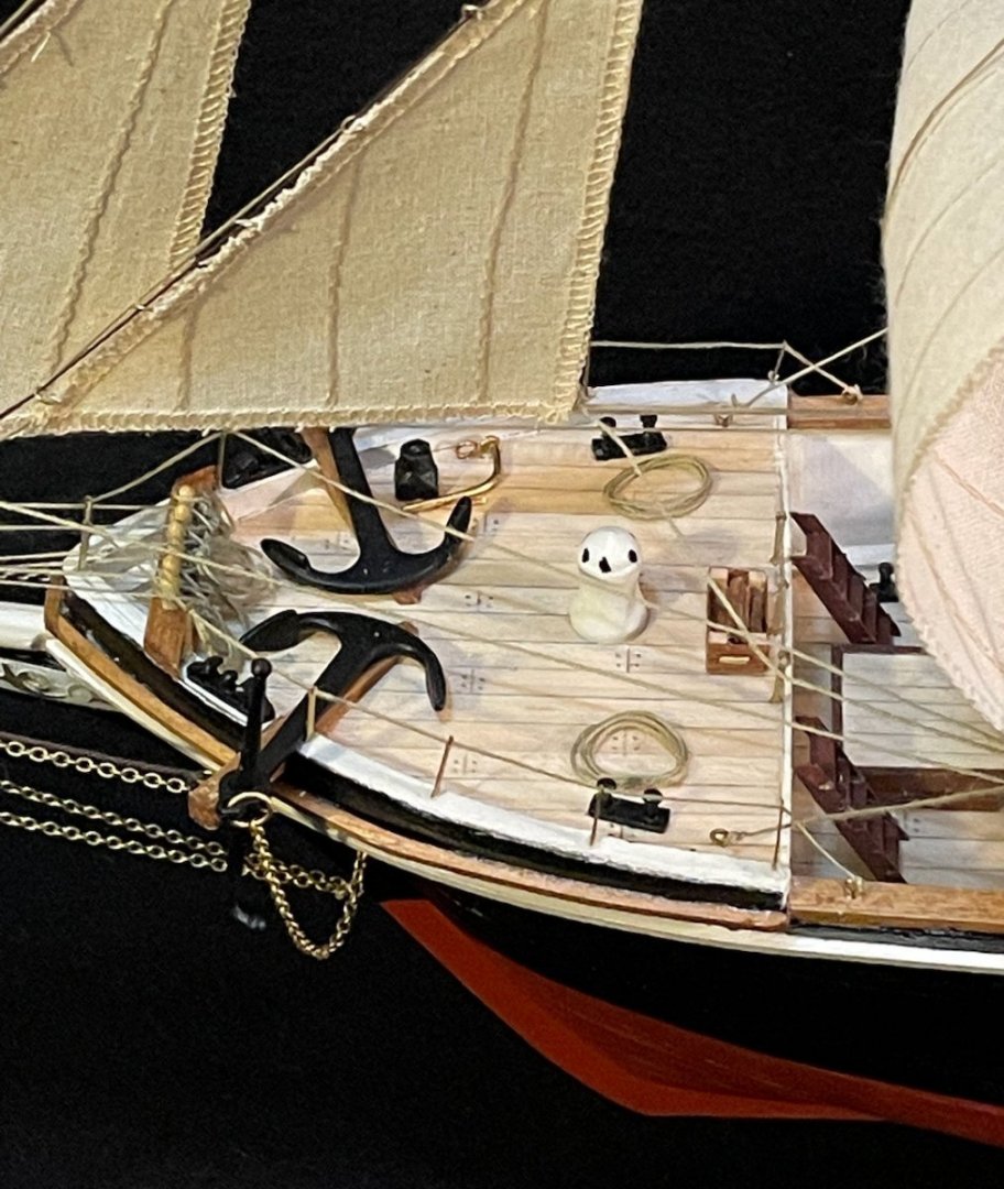
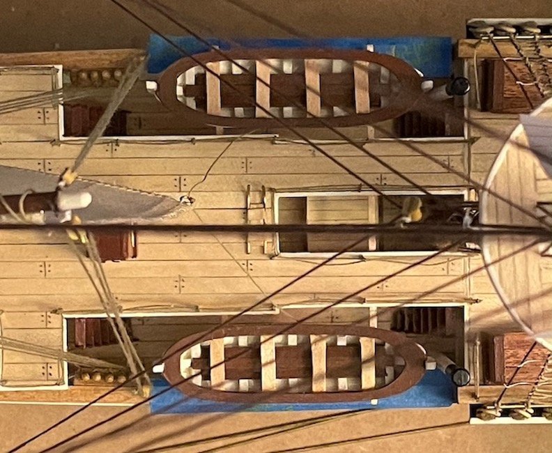
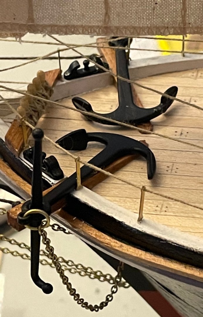
As I study the photo carefully, I notice that the stanchions immediately forward of the catheads have a bit more wear-and-tear than the others, particularly near the bottom. Those same stanchions, and possibly the ones just behind the catheads, also are seated differently than the others; there's a bit of a gap at the bottom. From this, I would guess that they pulled out those stanchions, rather than taking down the lines. Based on the equipment visible in the photo, I'm assuming that they first drew up the anchors using the capstan. Then, using a combination of the portable davit and a block hanging down (from the mast top? See right side of the photo.), they brought the anchor over the side and under the rope. The stanchions closest to the catheads might have been pulled out and slid down the lines to be out of the way. Purely conjecture, of course...I wish I could find film footage of a crew stowing their anchors in this way!
-
Johnny, Getty Images seems to have a pretty complete set of Frank Hurley's photos, which is why I link to them so frequently in my build log. Although this link suggests there are 163, be aware that most are Hurley's, some are of the replica Endurance used in the film with Kenneth Branagh as Shackleton, and some are only indirectly related to the expedition. The National Library of Australia preserves almost 11,000 of Hurley's photos from throughout his career, but I haven't had the patience to browse the whole collection and find the photos of the Endurance expedition. As far as copyright, Hurley's photos are protected for 70 years after his death, so they don't enter the public domain until 2032. Portsoy, I haven't found many great photos of the hull below the waterline. However, this one appears to show wood planks without copper plates. This photo of the Endurance in a London drydock suggests that there was something reinforcing the stempost, maybe it was copper or some other metal?
-
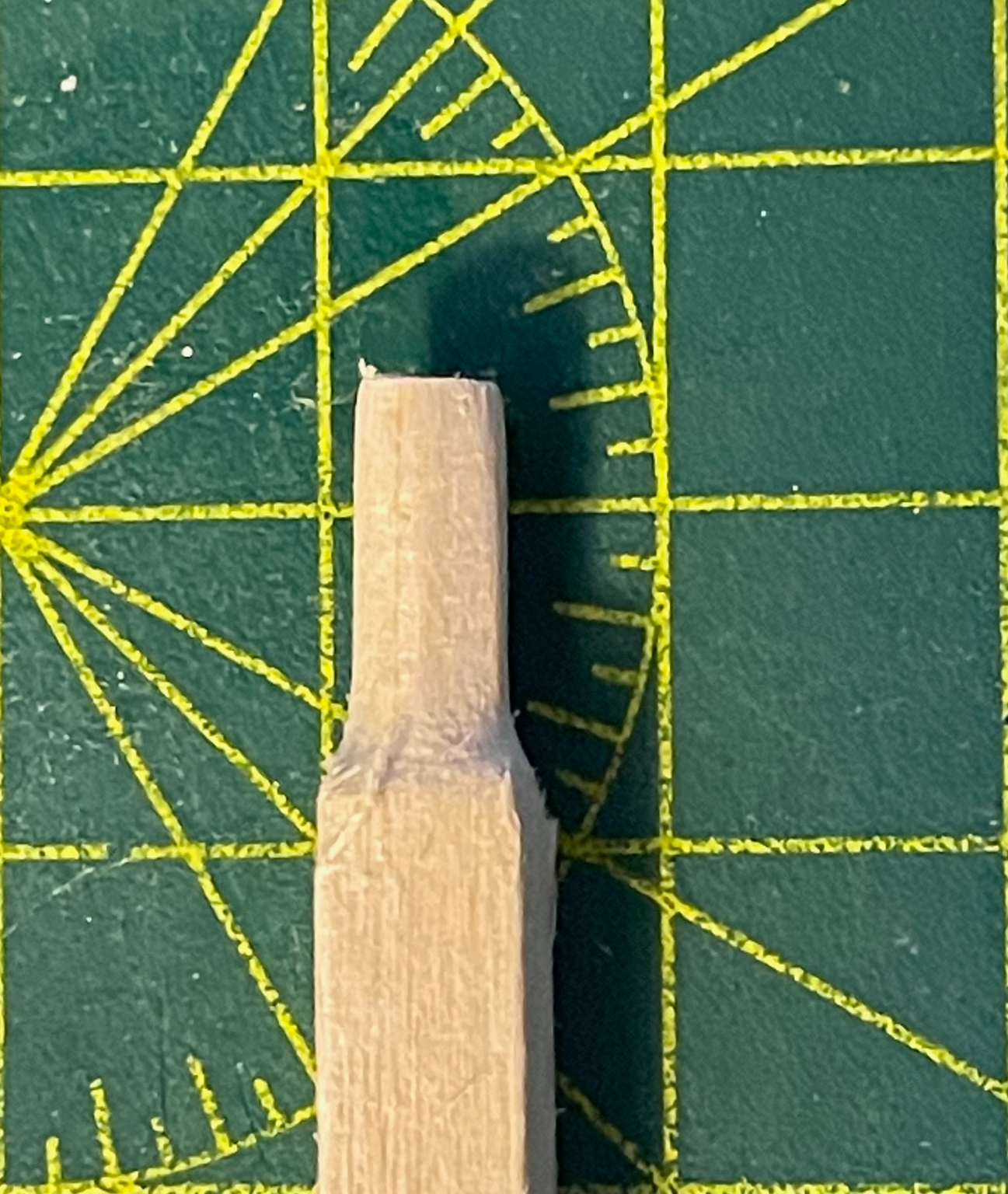
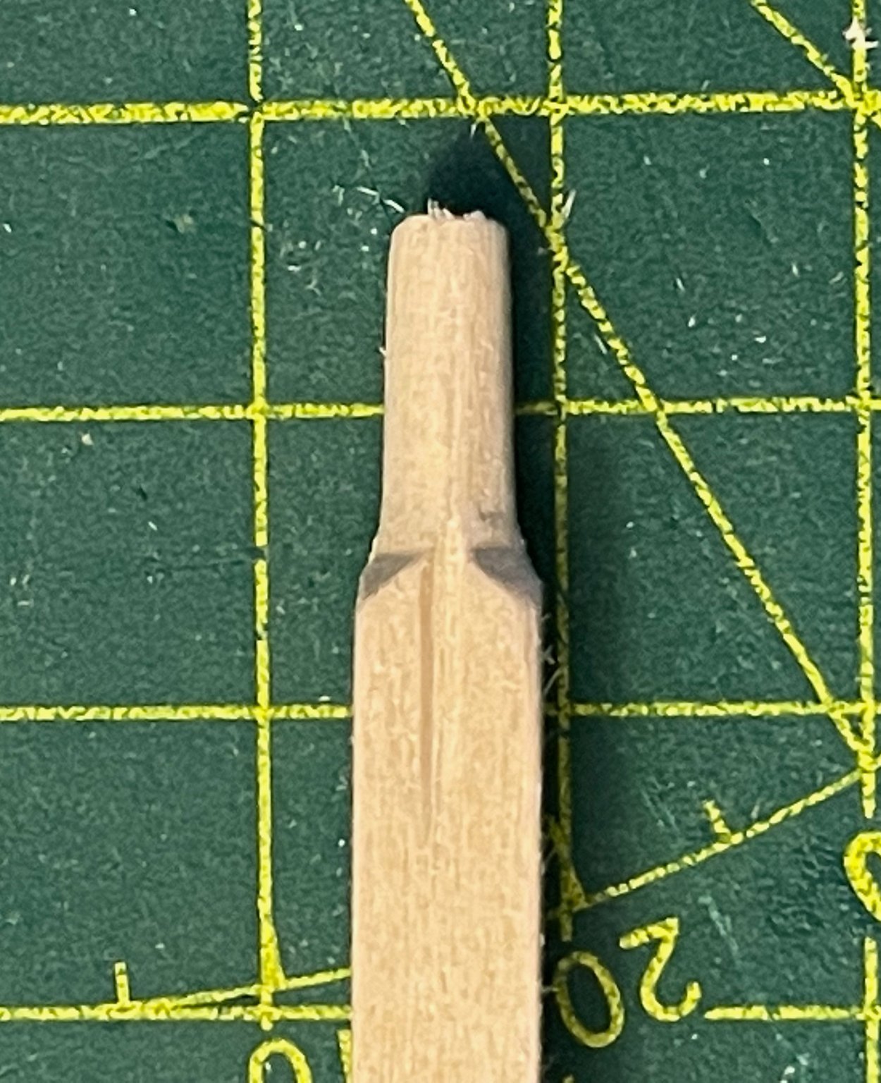
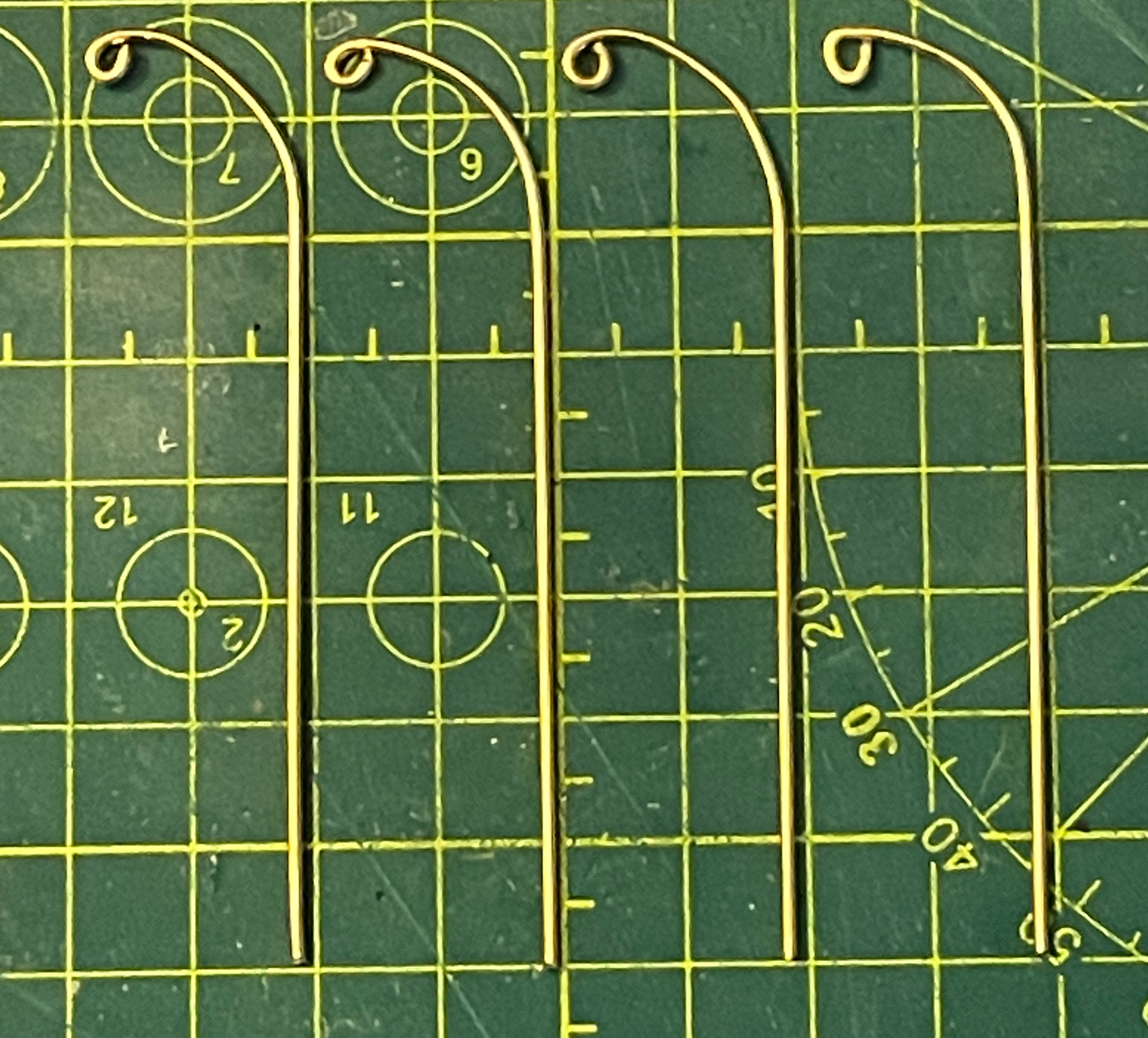
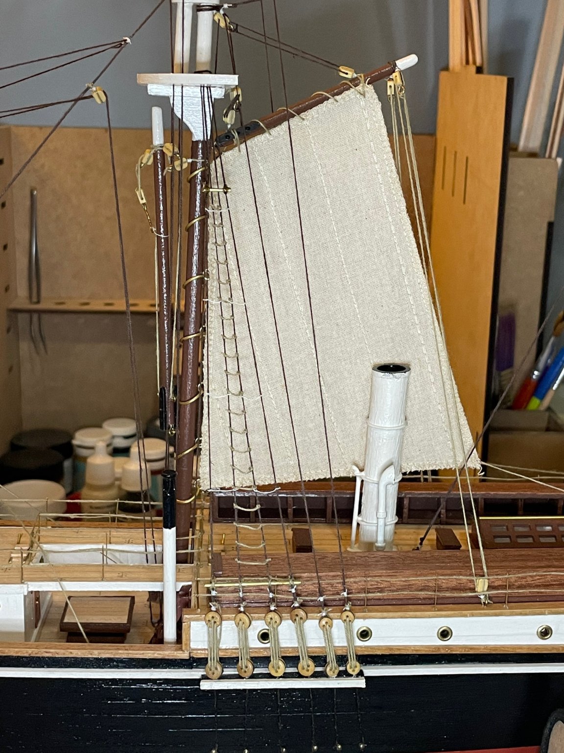
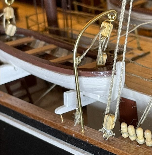
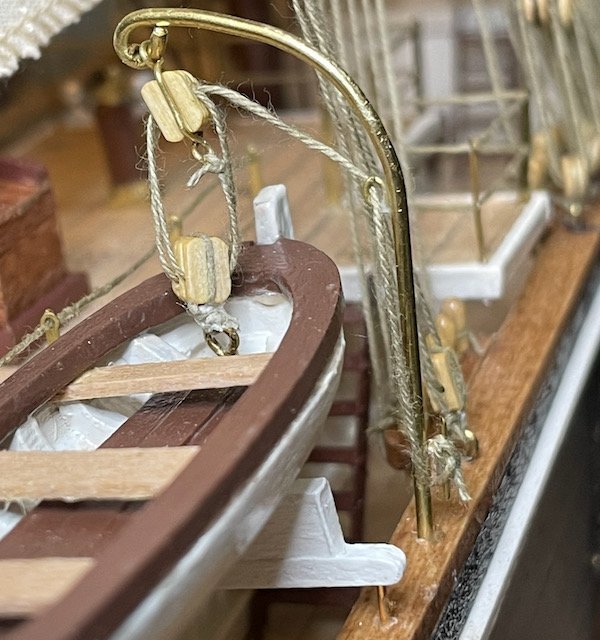
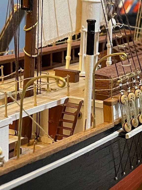
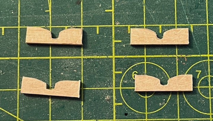
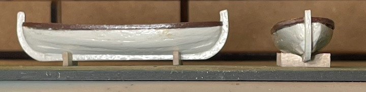
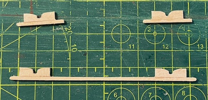
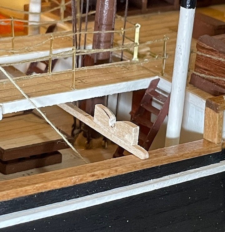
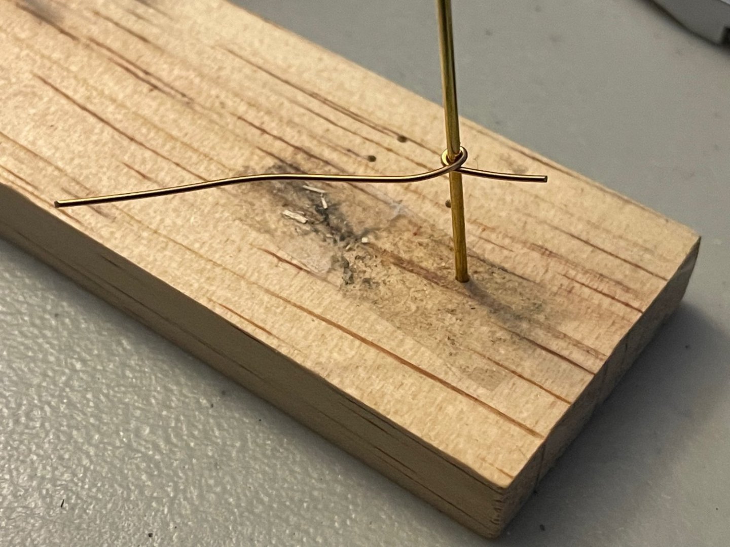
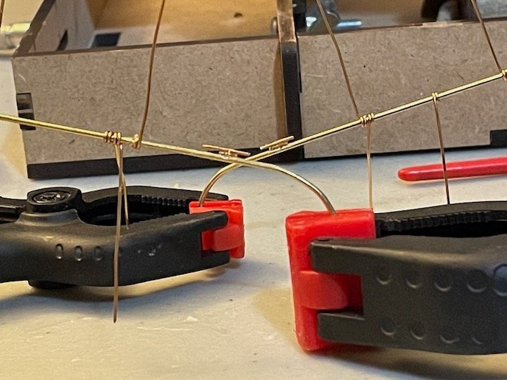
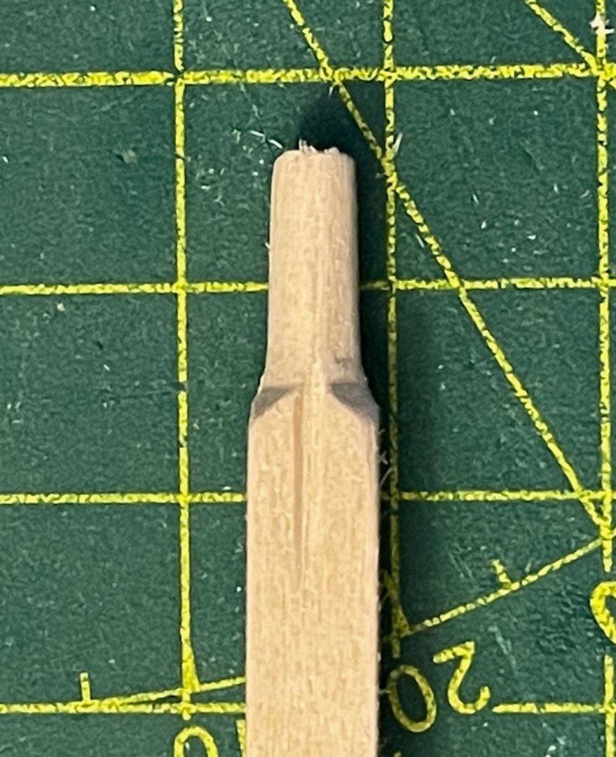
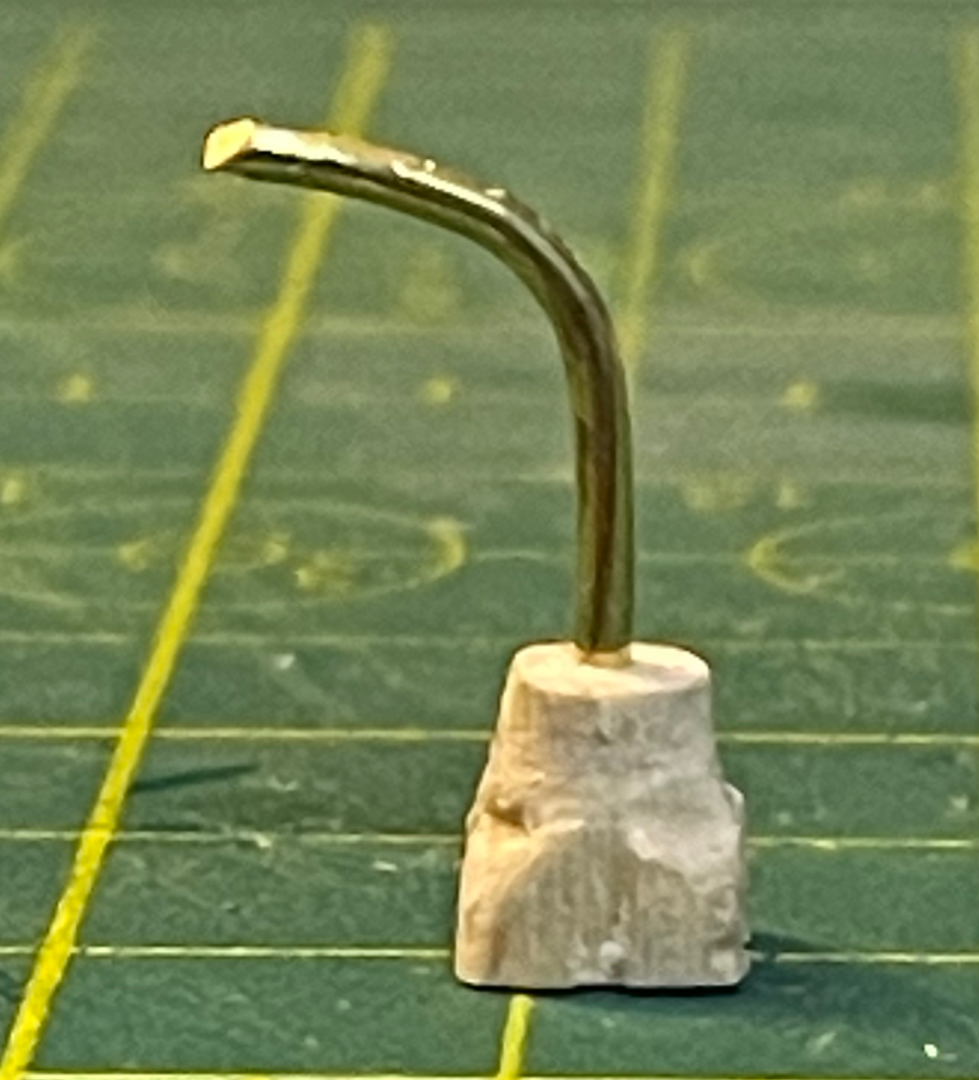
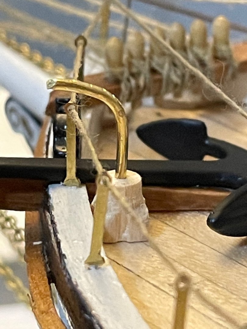
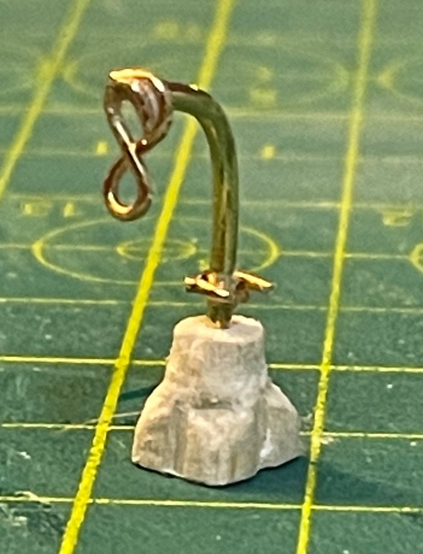
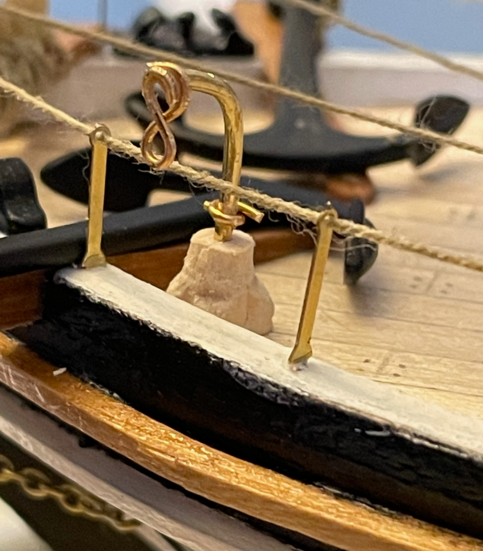
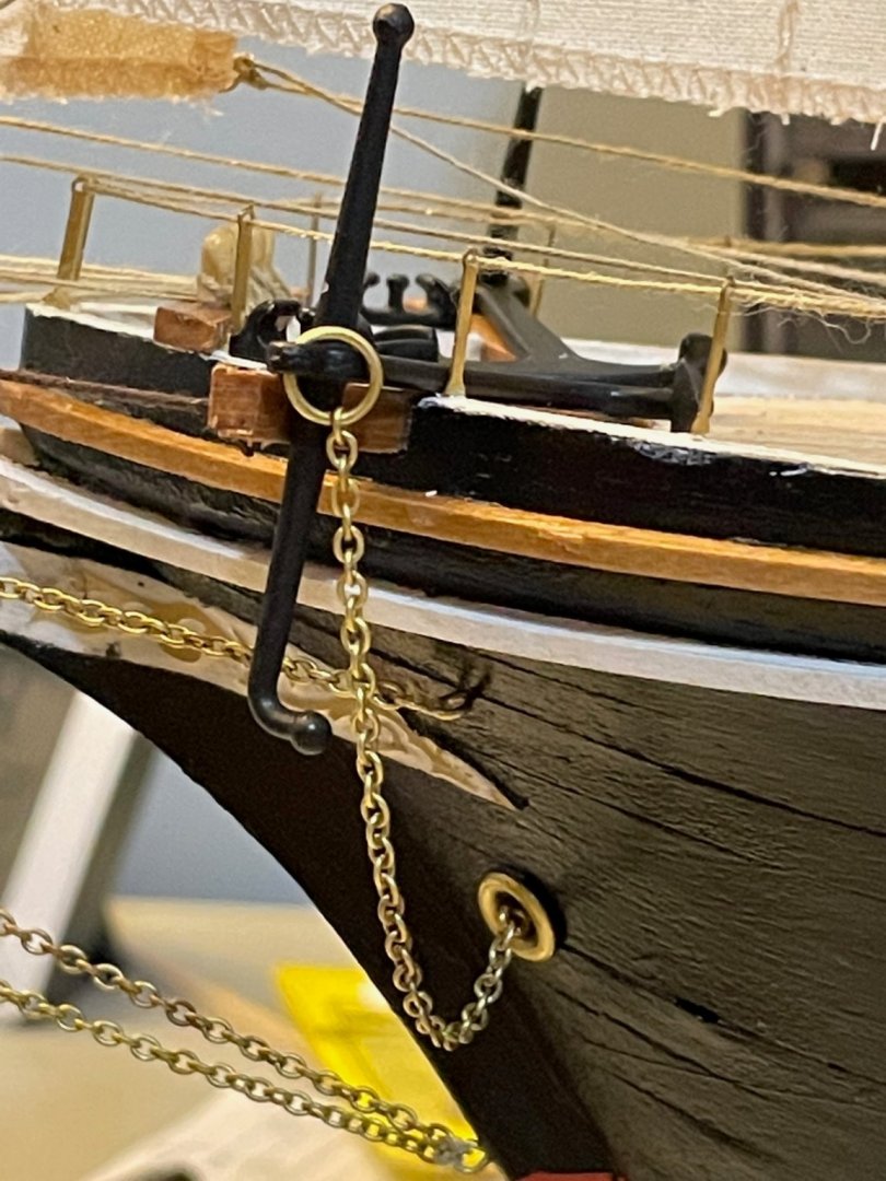
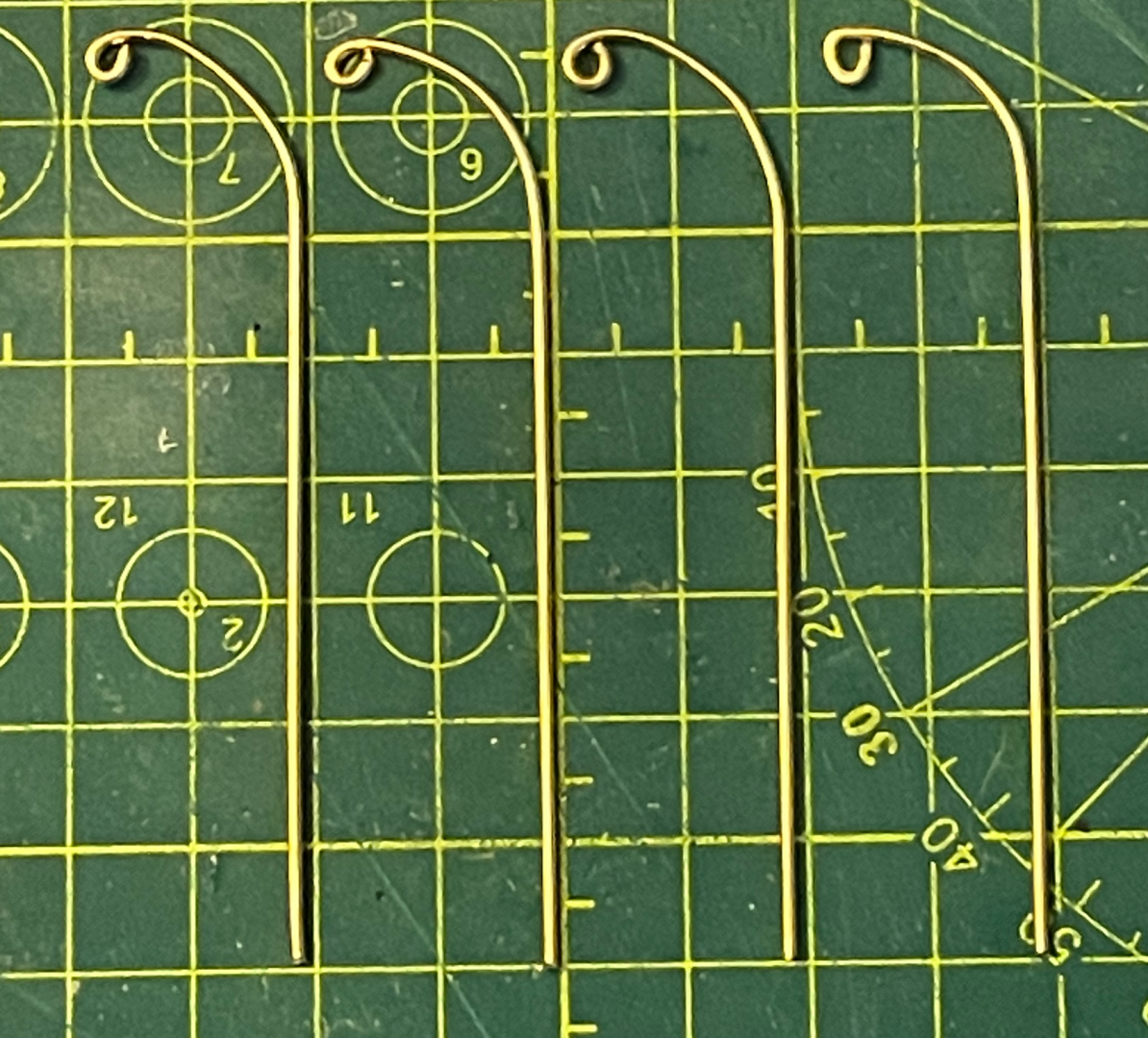
(Moderators: sorry for the ridiculously large size of some of these photo files. I ran into the dreaded Error Code 200 and could only get around it by changing those photos to PNG format.) Back at the Endurance after an intense couple of weeks working on writing projects. I haven't made much progress during this time, but have accomplished a few things. I'm slowly making progress on the remaining ratlines, lifeboat davits, and the anchors. Not much of interest to show on the ratlines, so on to the lifeboat davits. I've now fashioned all four quarterdeck davits. This has been a pretty frustrating process, since I've never done anything quite like this before. But at this point, I'm mostly satisfied. They are all almost identical in shape and size, though the loops at the top are pretty inconsistent. I got better as I went, so I may redo the one on the right...at the very least, it'll be hidden on the backside when the ship is displayed. I still need to fashion the eyebolts to mount them on the hull. For the anchors, I've spent quite a bit of time studying this photo of of the foredeck, along with the photos of the ship under sail. Of particular interest is that the anchors seem to have been stowed on top of the cathead davits, a task that appears to have been accomplished, in part, by using a portable davit with a pedestal base. In Frank Hurley's photo, the davit has been laid down between the port bollard and the capstan, while the pedestal base is still next to the starboard cathead davit. I've decided to install the anchors in similar fashion. (I also need to touch up some paint after handling the anchors so much...) . I also decided to get ambitious and make that portable anchor davit. I started by rounding the end of a 6x6mm piece of wood (1st photo). Then I used a three-square file to angle the corners and to carve channels in the middle of each side (2nd photo). After trimming off the ends and drilling a hole, I tested the fit and shape of a piece of brass rod, both on the cutting mat (3rd photo) and on-deck (4th photo). Finally, I glued on two pieces of brass wire to function as the eyebolt loop and the crank that's visible in the photo of the foredeck; again, I took photos of it on the cutting mat and on-deck (5th and 6th photos). Once the glue is securely dried, I'll paint both the davit and the base with the same matte (metal) black paint that I used on the anchors. I'm not attaching the davit and the base to each other, though, and instead will replicate Hurley's photo. . . . . . Next steps: paint the anchor davit and base, prepare the eyebolt mounts for the quarterdeck lifeboat davits, continue working on the ratlines.

-
For the lifeboat davits, I've decided to go with my prototype from the other day. Short of ordering eyebolts directly from OcCre (with international shipping, etc), I can't seem to find any that match what's in the kit. OcCre's are .7x10mm, so I could probably get away with .75x6mm eyebolts, which are easy enough to find. But since the goal is a snug fit around 1mm-diameter brass rod, I don't want to go any larger. In the end, I've decided to get some 22-gauge (.64mm-diameter) brass wire and make my own. I've been plugging away on the lower ratlines and have finished the portside mainmast. It sure is easy to install these when you have room to maneuver and when the line of sight isn't crossed by so many ropes! I'm moving a lot of faster on these than I did on the foremast. They still aren't perfect, but look a lot better than the ones on the foremast! I'm starting to wonder if I waited too long to tie off the foremast shrouds and install the ratlines there, but that's just second guessing myself; doing that sooner would have made something else more difficult. You'll also notice the sheer poles at the bottom and the top. These are tied into place with a very simple square lashing. The upper one is only lashed to the outer shrouds, since the futtock shrouds will be lashed to the middle of the sheer pole. (Note: in this kit, the futtock shrouds are the same rope as the upper shrouds. It just runs through a hole in the mast top.) Next steps: install the remaining ratlines on the main and mizzen lower shrouds, finish painting the anchors, fashion the lifeboat davits.

-
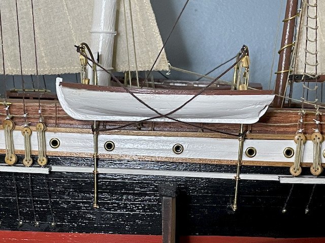
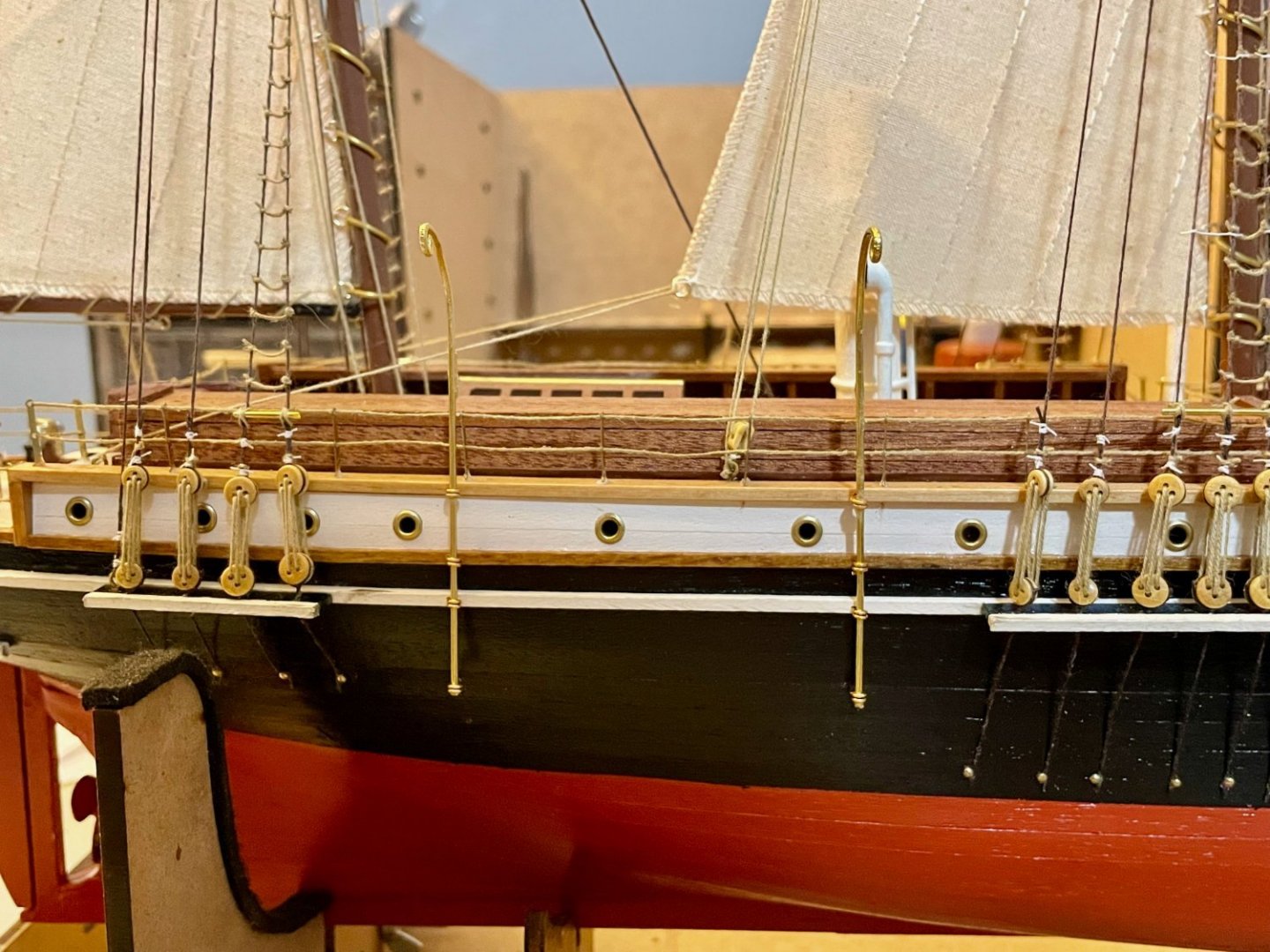
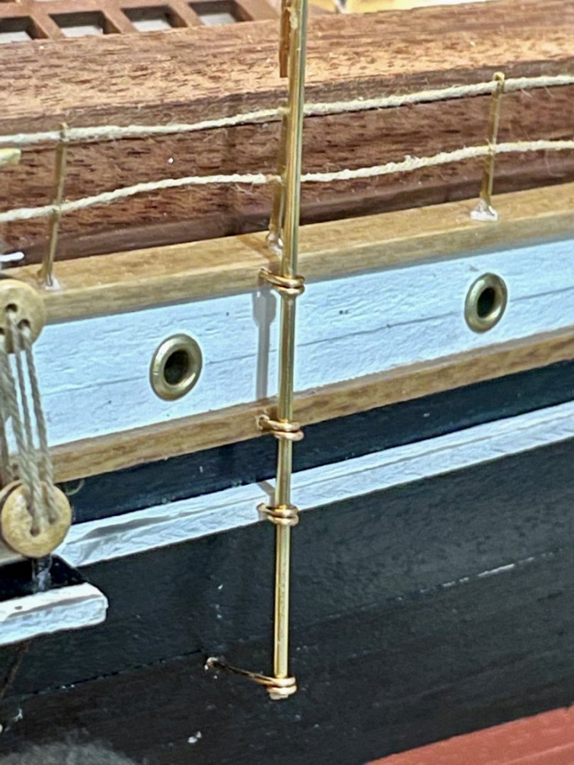
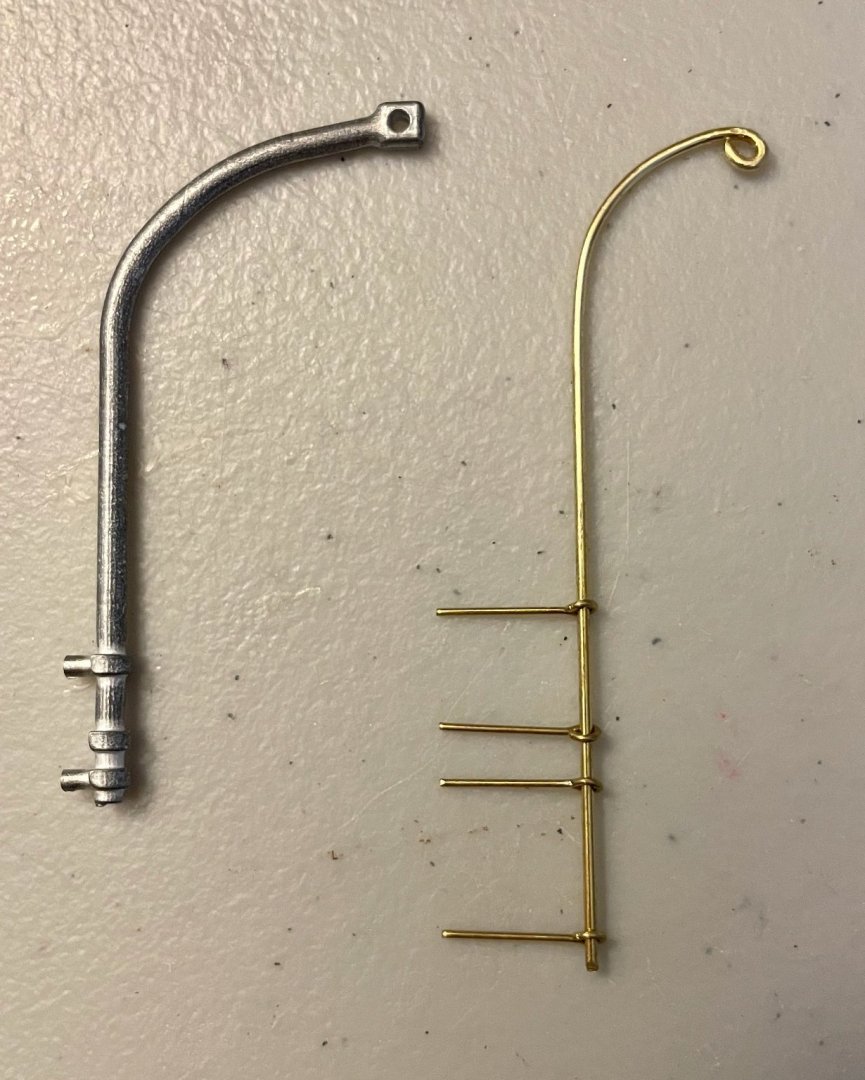
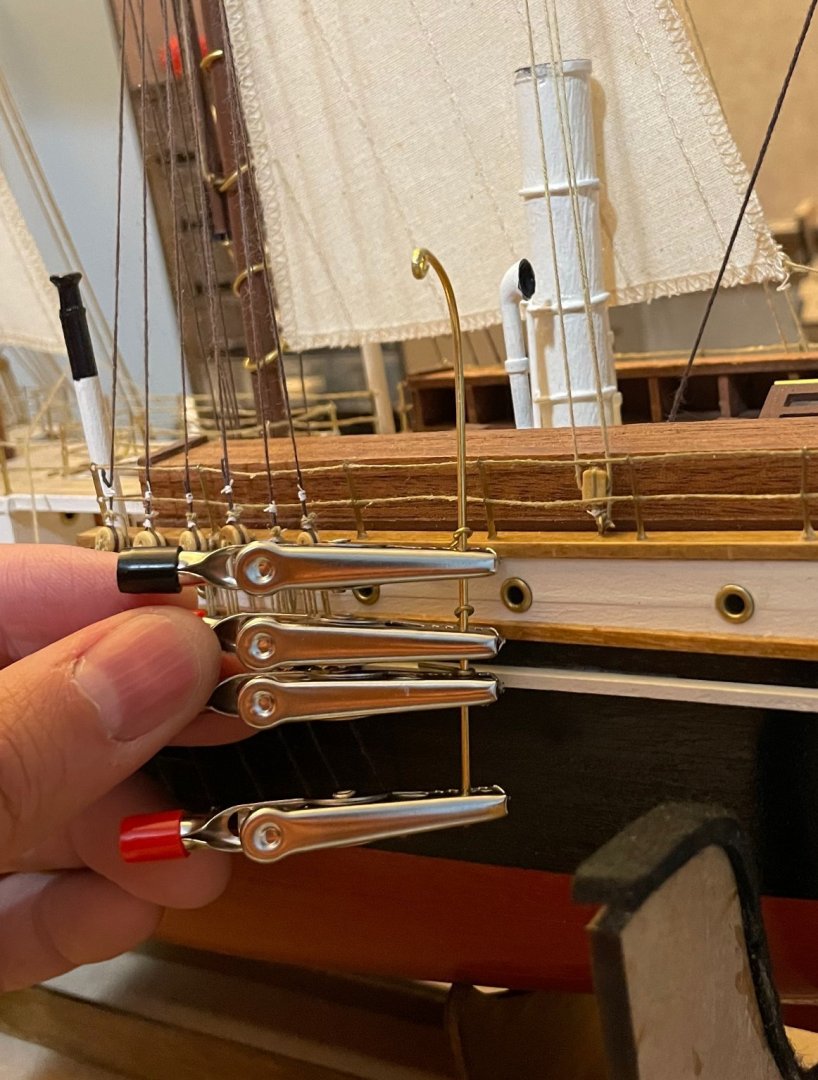
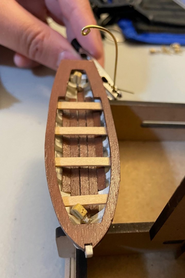
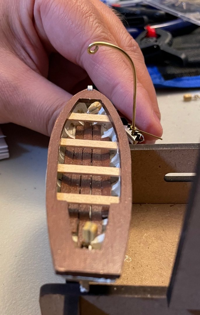
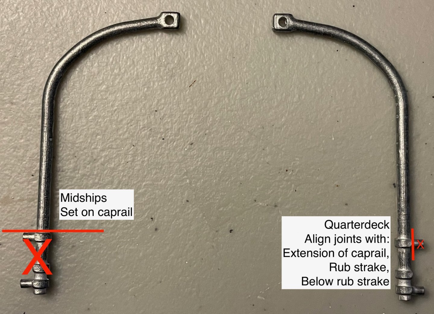
Keith and Johnny, thanks for sharing your thoughts! As I've continued to think about the lifeboat davits, I've come to the conclusion that I have two choices: adapt OcCre's davits or fashion my own along the lines of what Keith is planning. Both involve some significant work to make them pleasing to my eye, so there's no easy way out. At the moment, I think that OcCre's just look too heavy and too out of scale—particularly for how I would like to arrange the davits at midships. So, tonight I made some sketches, did some math, and then fashioned a prototype. Here's my prototype for the quarterdeck davits (right) alongside OcCre's. The eyebolts aren't attached yet, but for the photo are aligned in approximately their final positions. If I end up using this, the top eyebolt would be attached to the quarterdeck caprail (or is it a covering board?), the second to the plank connecting the main and aftdeck caprails, the third to the rub strake, and the bottom one about halfway between the rub strake and the waterline. The crucial dimensions are 34.5mm from the bottom to the quarterdeck caprail, 26.5mm from the quarterdeck caprail to the beginning of the curve, and 29.5mm for the curved portion at the top, plus a bit to form the eye. In testing the look, I first held it up to the hull, with gator clips marking the positions of the eyebolts. One of the crucial targets for me was the observation that the tops of the davits were approximately even with the tops of the air intakes (I think that's what those are, next to the smokestack?). . I also needed to check the clearance for the lifeboats. It's close but I think will work; there are millimeters to spare, which would be inches at full scale. Here are a couple awkward photos...I really needed a third hand here. . If I'm still satisfied tomorrow, then I've got one down and seven to go. Unfortunately, that means I'll need to pick up some more eyebolts and I'm not sure what size to get. Model Expo lists 1/16" x 1/2", 3/32" x 9/16", and .75mm x 6mm. I get that the second number is the length, but is the first number the diameter of the wire, the inner diameter of the eye, or the outer diameter of the eye?

-
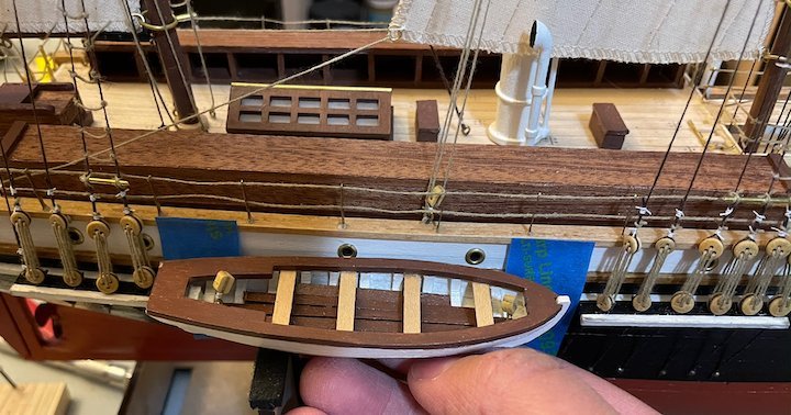
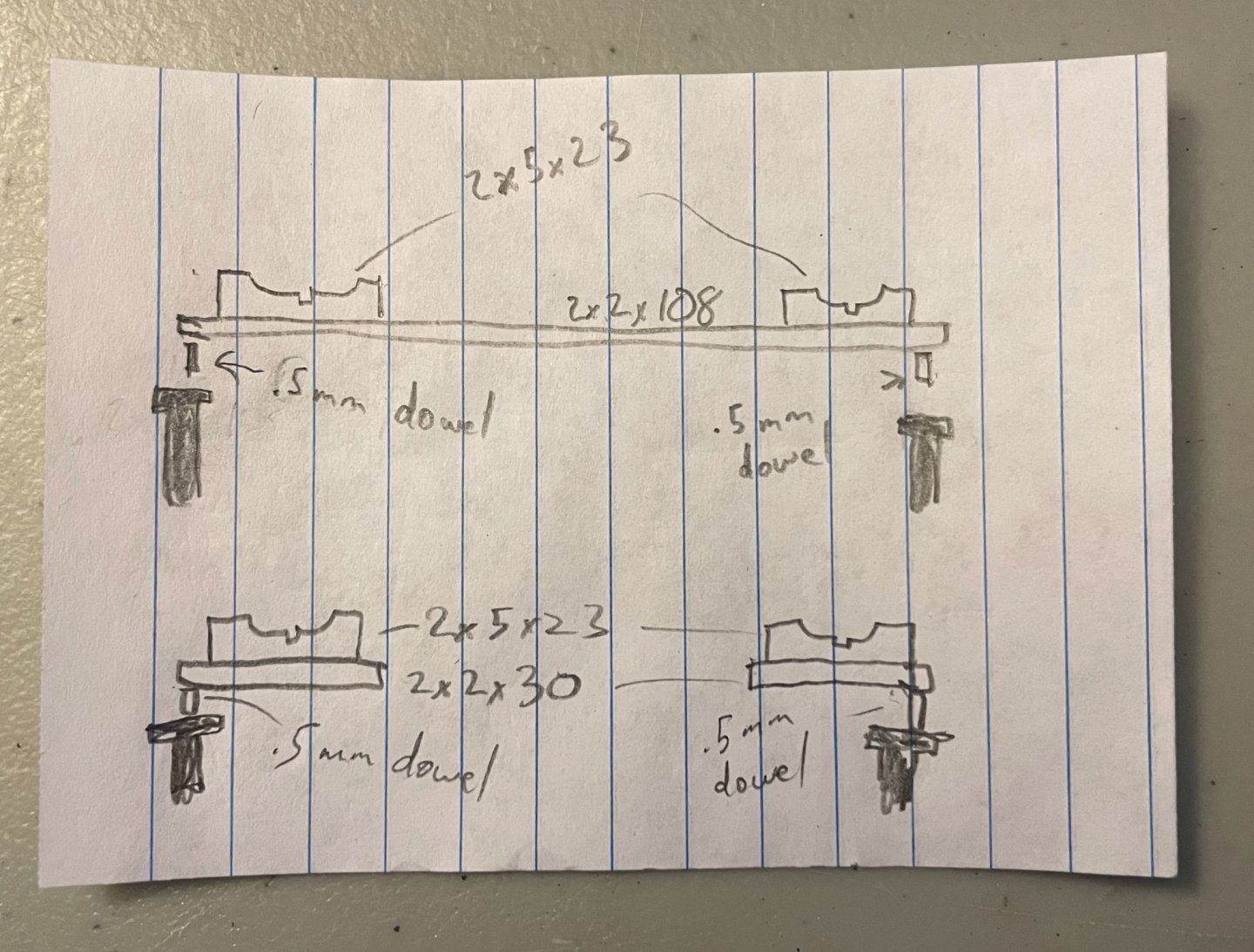
I hit my writing deadlines and so am taking some time again to work on the Endurance. The lifeboat davits have been on my mind lately, so I spent some time today working through that problem. OcCre's plans are pretty simple for these: the two pegs on each davit are attached to the hull on either side of the rub strake. And done. But...this doesn't quite jive with the historical photos and I'm feeling ambitious. The davits provided in the kit are too thick and too short. Also, note in this photo, note that the midships davits are mounted on the caprail and that the midships lifeboat is mounted inboard, on cradles. One of the midships davits is turned inboard (which isn't possible with the kit's davits as they come out of the box); the one that's turned outboard is supporting the gangway. I've found three other photos that have good views of the midships davits and the cradles for the lifeboats: first shot from dock, second shot from dock, and view from quarterdeck. I'm going to stick with the kit's davits and am going to leave off the gangway, but I would like to mount the midships lifeboats on cradles. Here's where I'm at on that so far. First, the davits need to be trimmed. For the ones at midship, I'll be trimming them at the top joint. For the ones along the quarterdeck, I'm going to remove the top peg so that the top two joints align with the rub strake and the plank that continues the caprail; the bottom joint, with the peg remaining, will attach to the side of the hull. This will ensure that the tops of all eight davits remain at the same height and, I think, will allow for more secure attachments. The cradles should be fairly straightforward. The first sketch is my tentative design. The cradles themselves will be fashioned from 2x5 planks and will rest on 2x2 supports. Those supports seem to have been metal on the original ship, but I'll stick with wood since I have that stock on hand. The second sketch shows that the support for the forward cradles runs from the caprail to the side of the Ritz, while the support for the after cradles runs all the way across the ship, under the catwalks. In both cases, the ends of the support pieces are supported by dowels (or maybe that should be short brass rods?) attached to the caprail. In the second sketch, the davits (acting as paperweights!) are positioned in approximately their correct spot. I'm going to keep playing around with this for a bit, but I think that this will work out.

-
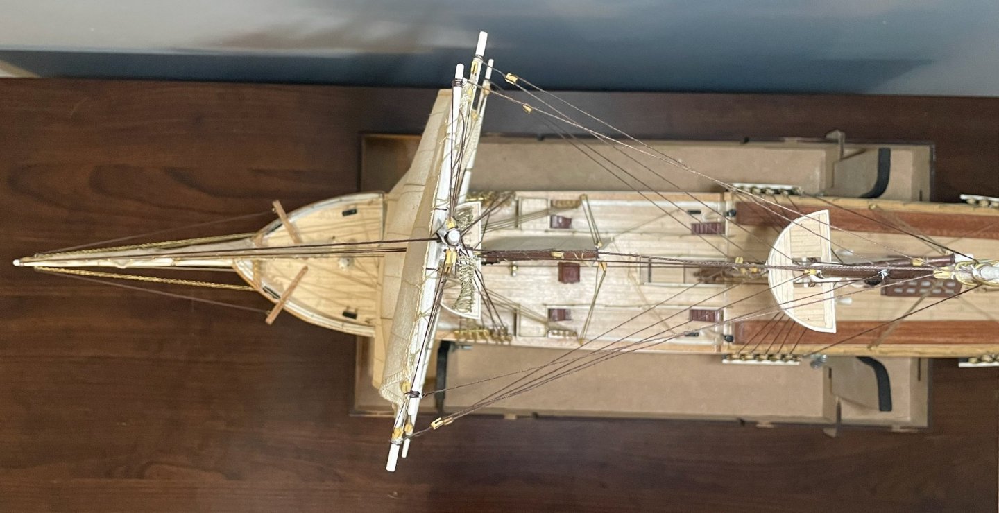
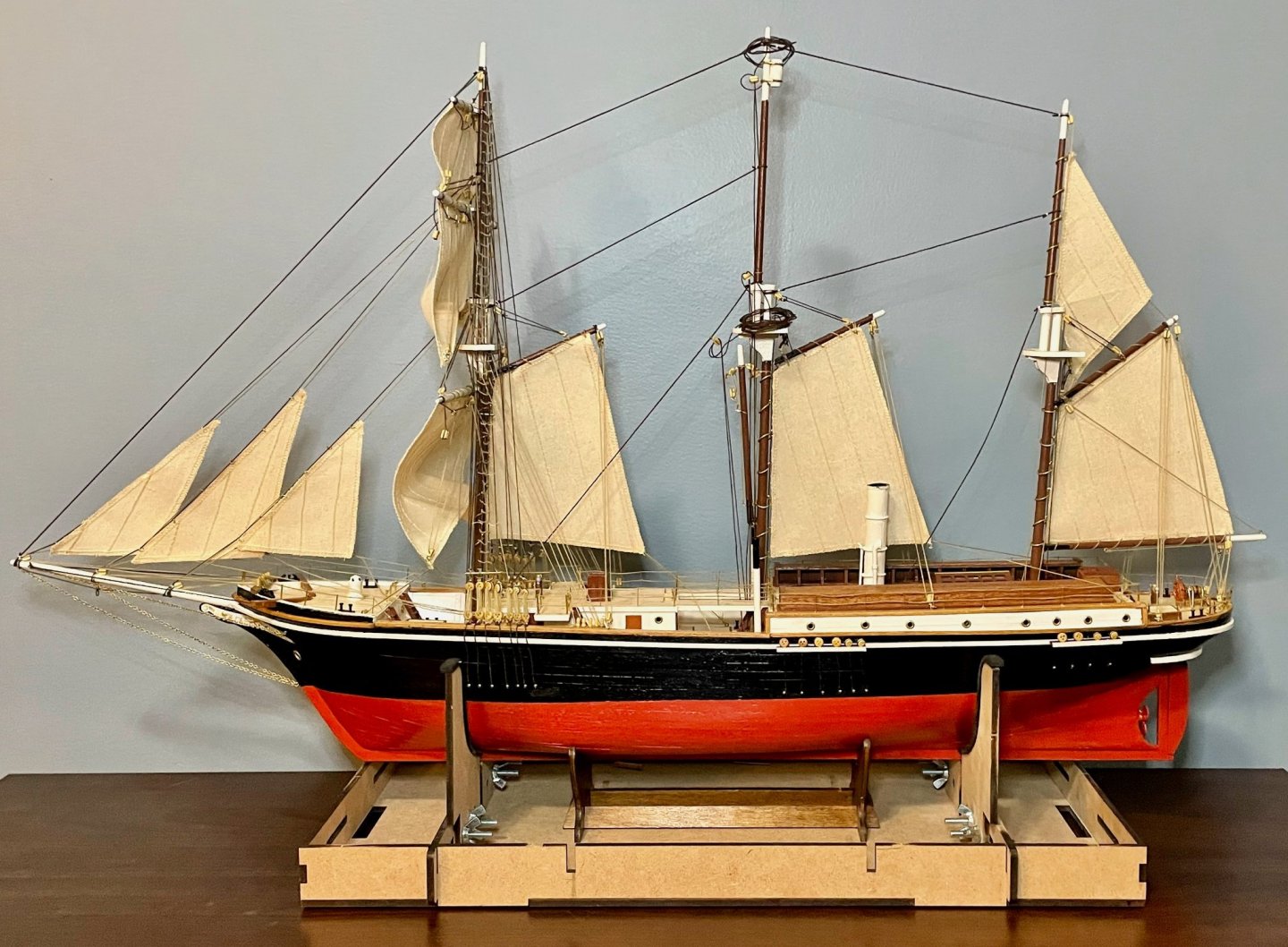
A bit more progress this week, bringing my Endurance to a satisfying place to set it aside for a bit while I finish up some writing projects. I've installed the lower shrouds and remaining stays on the main and mizzen masts. I've also finished the ratlines on the foremast and tied off the braces. So first, a shot of the full profile. And details of the main and mizzenmasts, showing the shrouds and stays: . Finally, an overhead view of the foremast, to show the braces. In Ship Modeling Simplified, Frank Mastini writes that the yards should not be set at the same angle to the wind, since the wind gets more aftward as you get higher. So, you'll notice in the photo that the upper topsail yard is set at the shallowest angle, the lower topsail yard in the middle, and the foresail yard (with the yardarm) at the sharpest angle. Given the camera angle, this is easiest to see on the starboard side. Next steps, once I get back to work on her: Add sheerpoles and ratlines to the main and mizzen lower shrouds, prepare the anchor and lifeboat davits for painting.
-
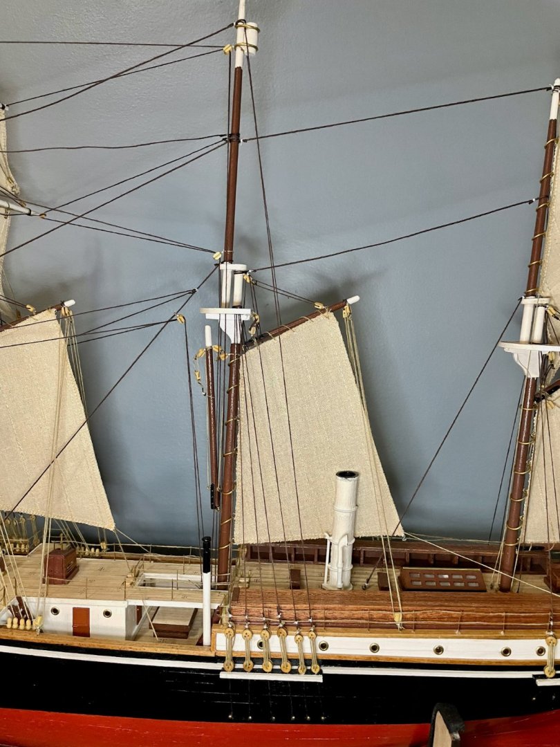
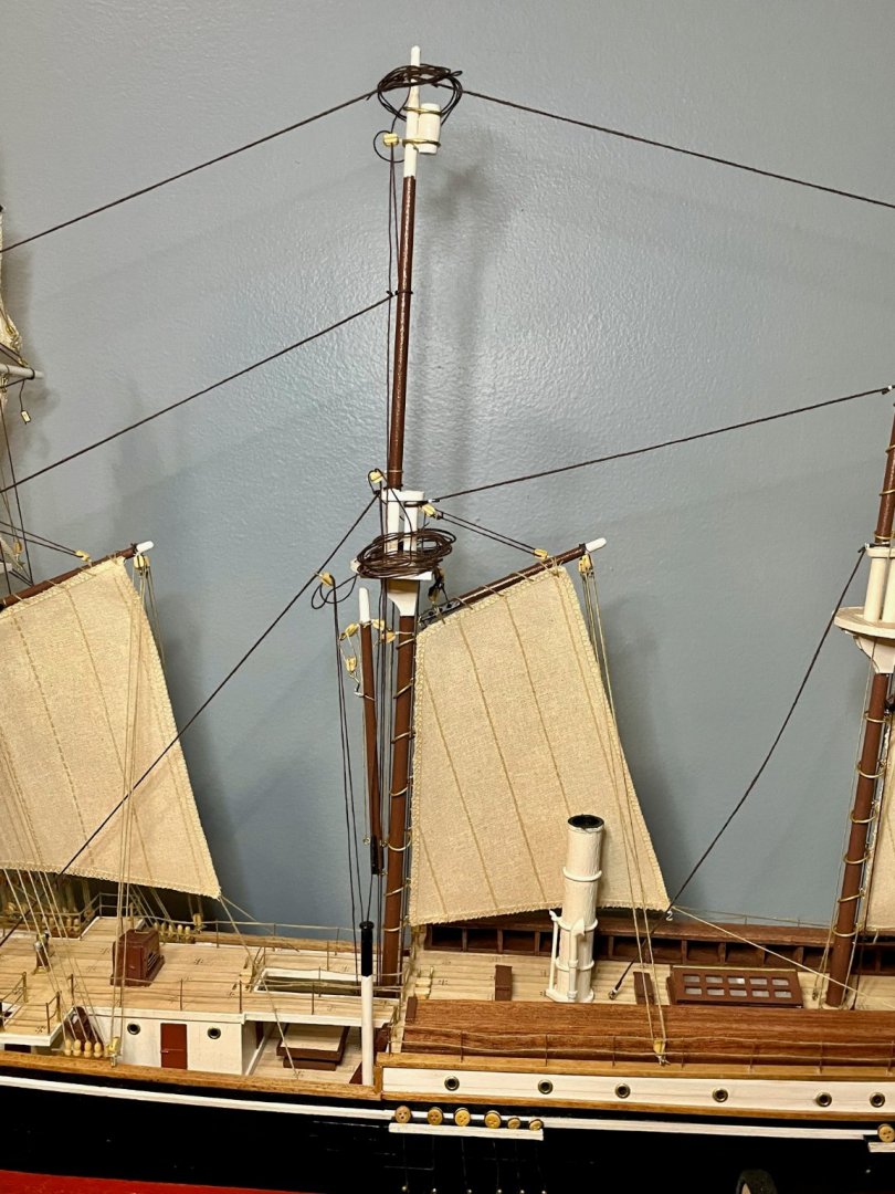
Wow, Keith, that smokestack looks fantastic! This is a great upgrade! The Ritz is coming together nicely, too. As for the windows: I noticed that in the cabins of the original ship, the windows narrowed from a square on the inside to a round porthole on the outside. Not sure if that was true in the Ritz, as well, though.
-
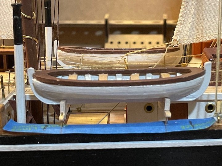
Well, I got on a roll today and spent a lot more time on the Endurance than I should have. Time well spent, if you ask me, but I do need to get back to work on a project with a looming deadline. The lifeboats are finished now and are just waiting for blocks to be installed (I'm waiting on some of those blocks to arrive from OcCre's warehouse). With those done, I've been digging in on the rigging. All of the ratlines are finished on the port side of the foremast; I still need to do the ratlines on the starboard upper shrouds. I've also installed the forestays for the main and mizzenmasts, as well as what remained of the running rigging on those masts. All that remains for those two masts is to install the shrouds, backstays, lanyards, and ratlines. So, a profile shot of the whole ship and details of each mast. Ratlines...ugh. As I've mentioned before, this is the first model I've made that features ratlines. After doing 65 of them, I'm getting better, but there's still a lot of inconsistency. I should be a pro after the finishing the remaining 180 or so, right? The wound thread on the mast top and the mast head are the ropes for the braces. I've run them up from the anchor points on the deck to their blocks. Once I've finished the ratlines on the foremast, I'll attach the braces to the yards. The gaffsail sheets are an interesting problem, as they seem to have been on the original ship; once the dog kennels were installed, the sheets don't appear to have run cleanly to their anchor points. For those working on this kit, plan ahead regarding the anchor points for the gaff vangs; space is very tight since these blocks are attached between the dog kennels and the railings. You'll make your work easier if you align the eyebolts perpendicular and the blocks parallel to the center line. There's a lot of rigging on the mizzenmast, but I'm generally happy with how it turned out. The forestay is sagging a bit, so I'm debating whether I should just rip it out and replace it while I still can. Although I rigged the ensign lift, I'm probably not going to use the kit's flag; in the photo I'm using for inspiration, the Endurance wasn't flying her ensign. (Looking back at the photo, the angle of the mizzen headstay is completely wrong...I may need to redo that rope, too.) For those building the kit, another place to plan ahead is with the anchor points for the boom vangs and ensign lift. These three blocks are close to each other, close to the railings (the block for the ensign lift is actually under the railings in OcCre's plans), and they are close to the steering mechanism (regardless of whether you use OcCre's housing or do something like what I did). Next steps: decide what to do about the mizzen forestay and headstay; install the remaining foremast ratlines; install the main and mizzen shrouds and backstays; start preparing and painting the anchors and lifeboat davits. There's still plenty of work ahead of me, but the end of this project is in sight!

-
Hi Bob, I *think* I’m using that term correctly…I’m referring to the gaps in the mast top against the mast. Here’s an image I found online, apparently from the 1859 Dictionary of Nautical, University, Gypsy, and Other Vulgar Tongues: