HOLIDAY DONATION DRIVE - SUPPORT MSW - DO YOUR PART TO KEEP THIS GREAT FORUM GOING! (Only 13 donations so far - C'mon guys!)
×


HakeZou
-
Posts
325 -
Joined
-
Last visited
Content Type
Profiles
Forums
Gallery
Events
Everything posted by HakeZou
-
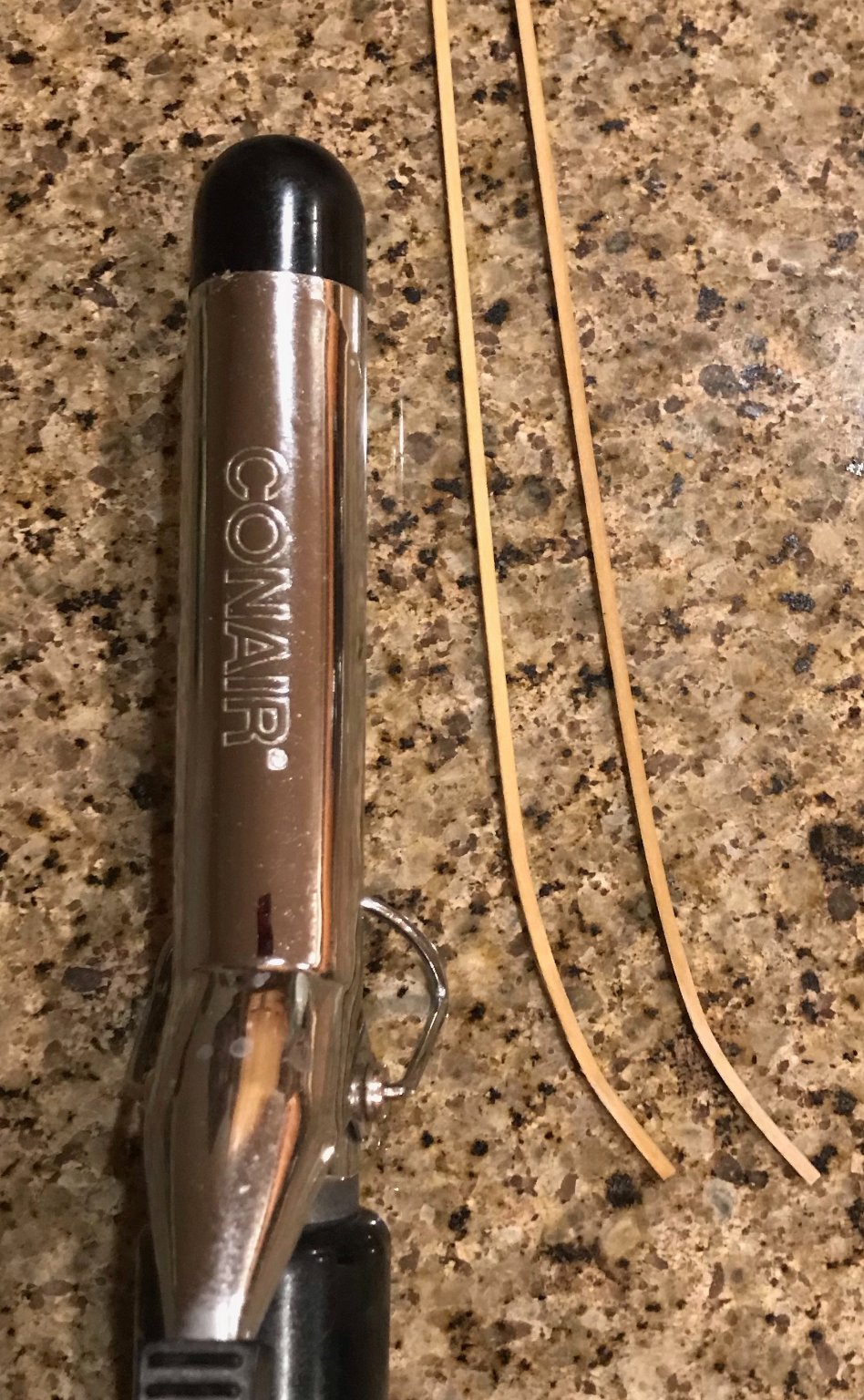
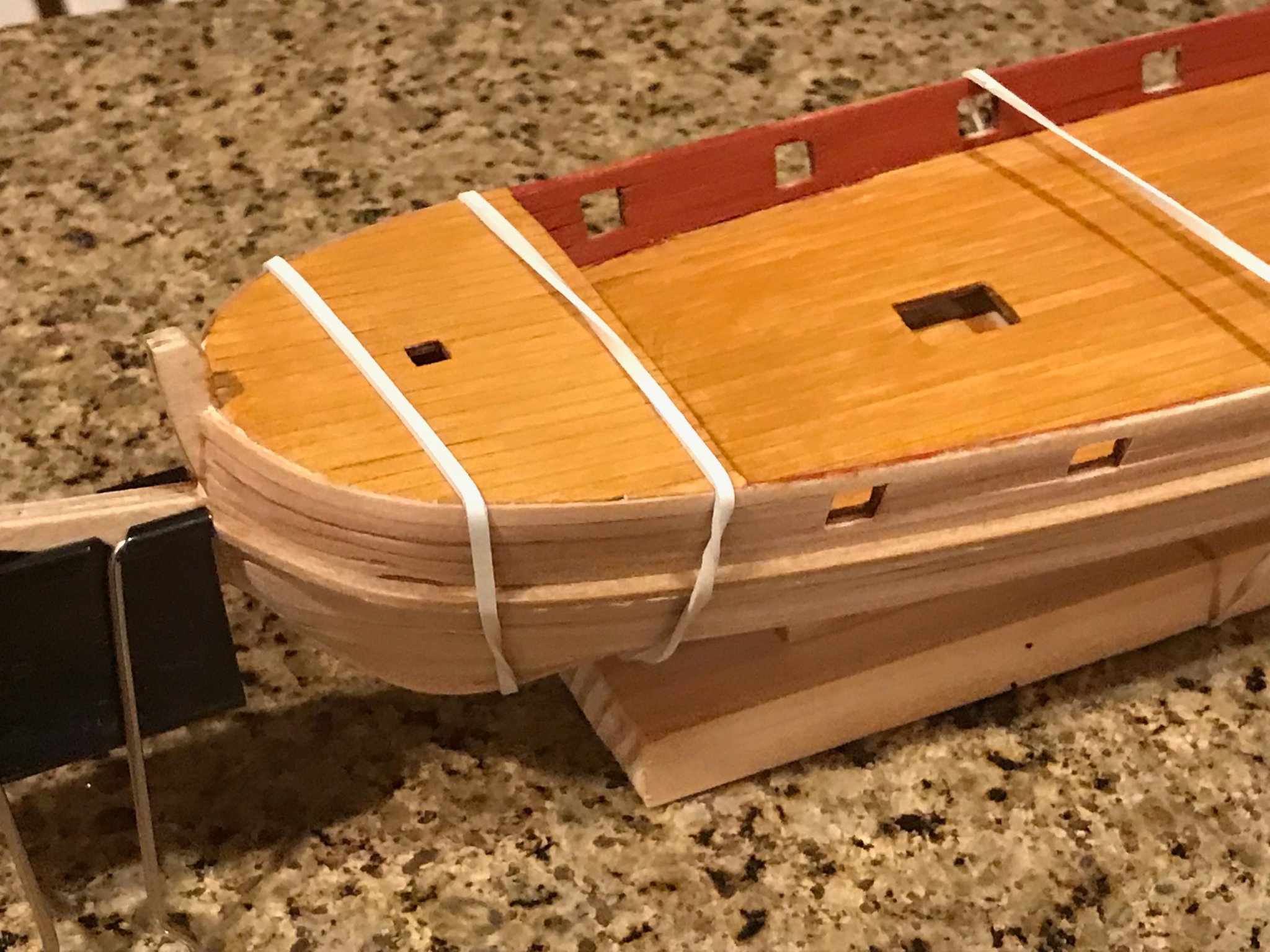
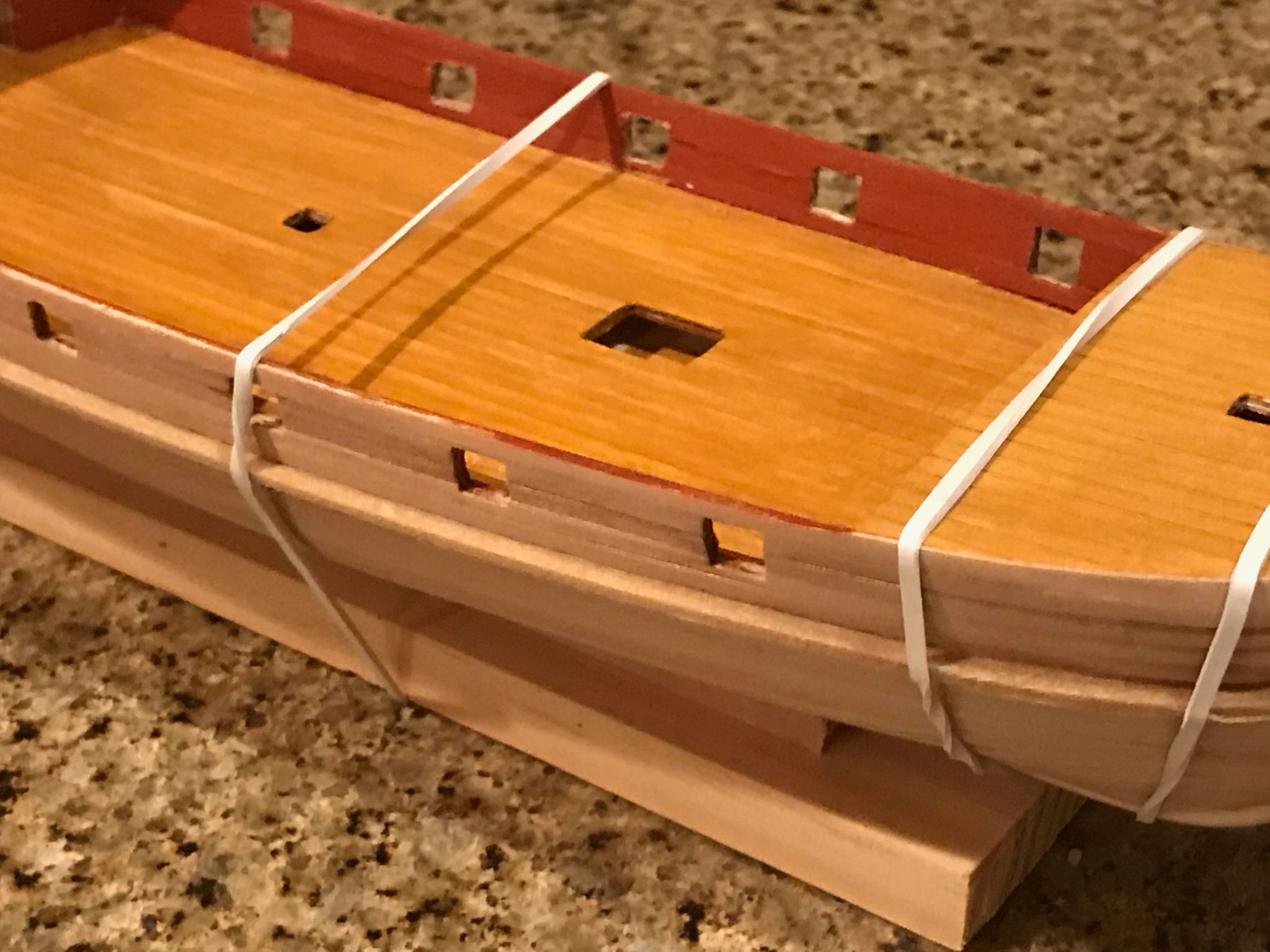
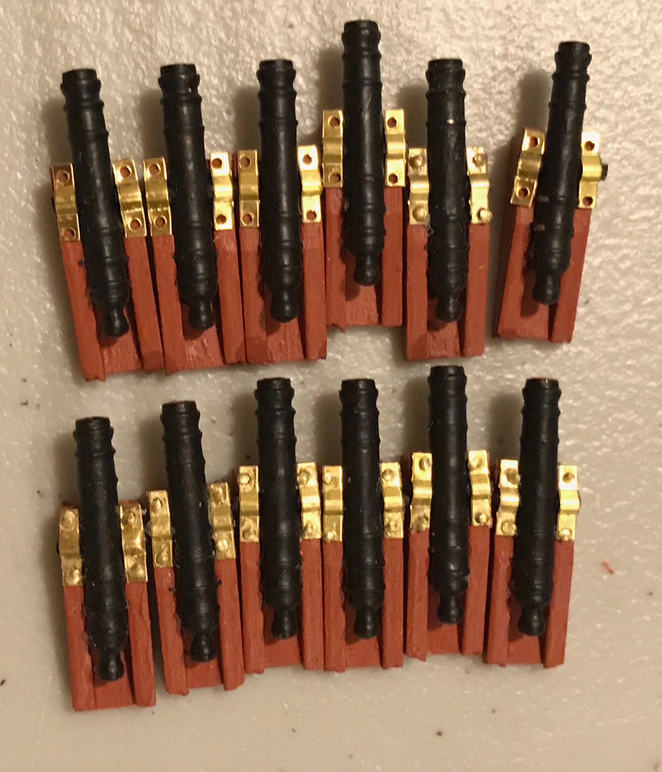
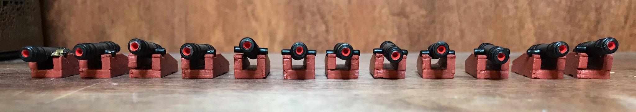
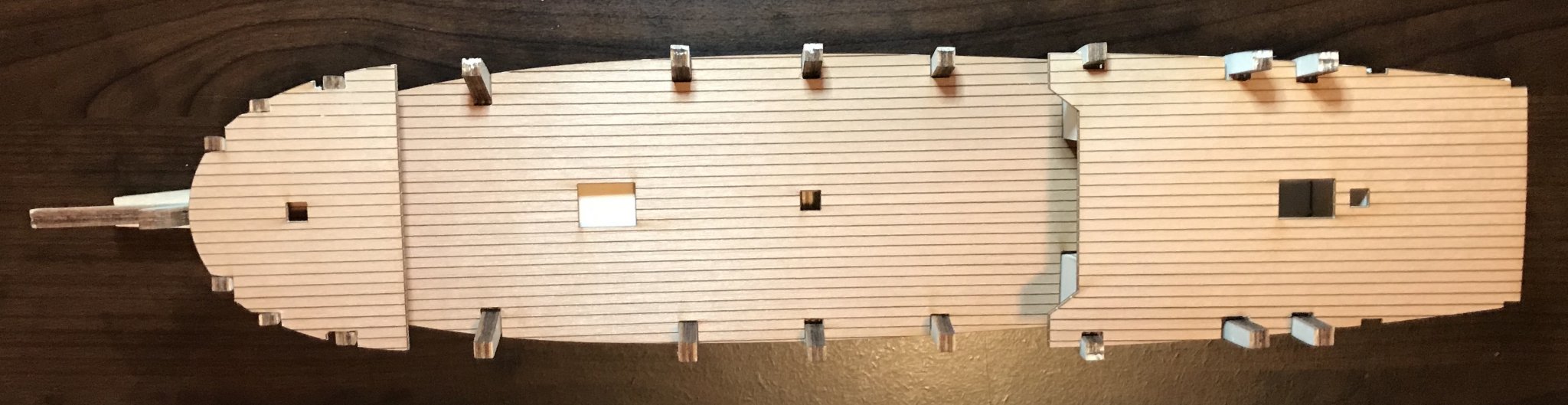
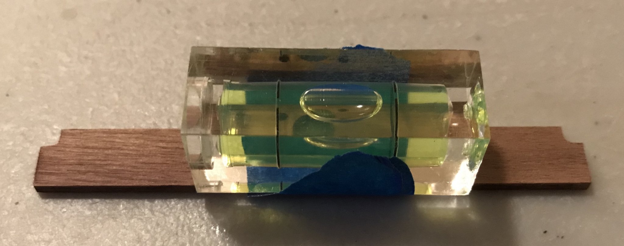
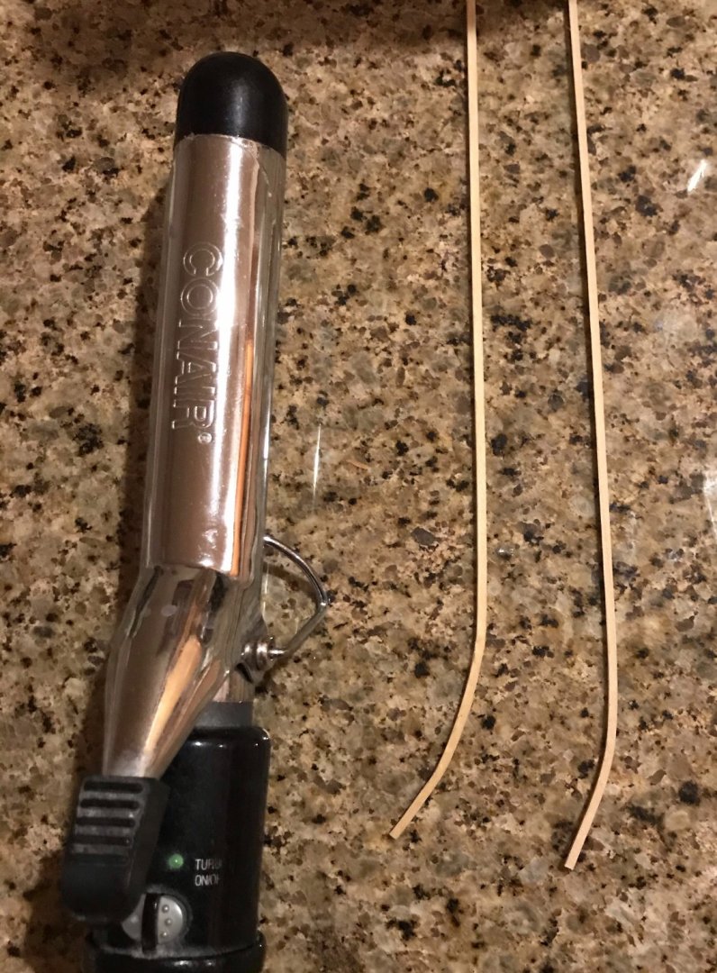
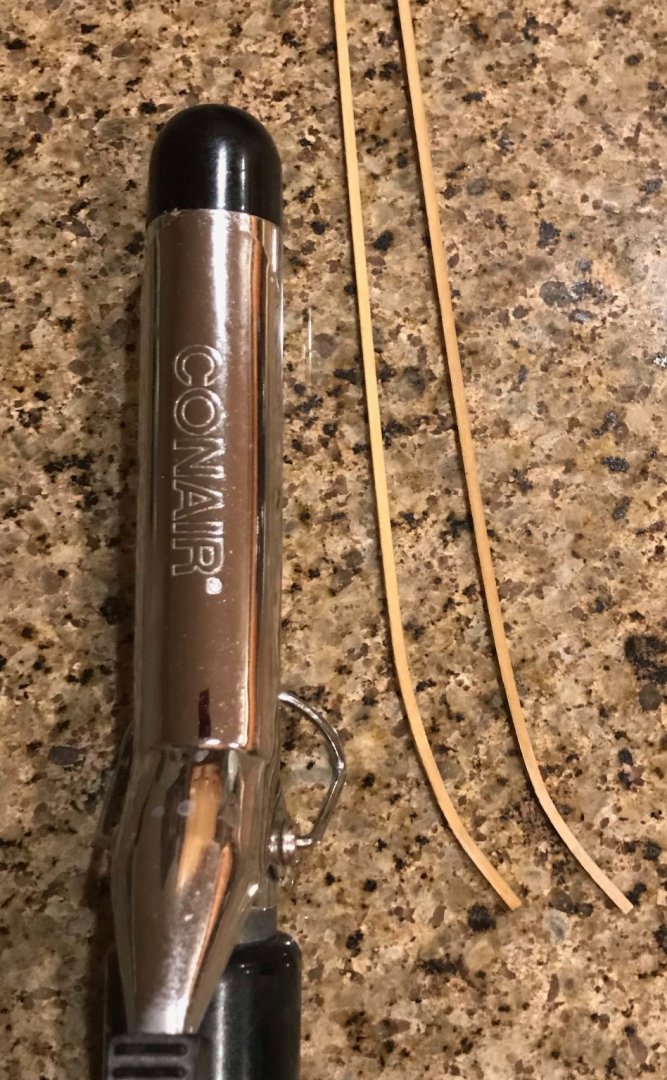
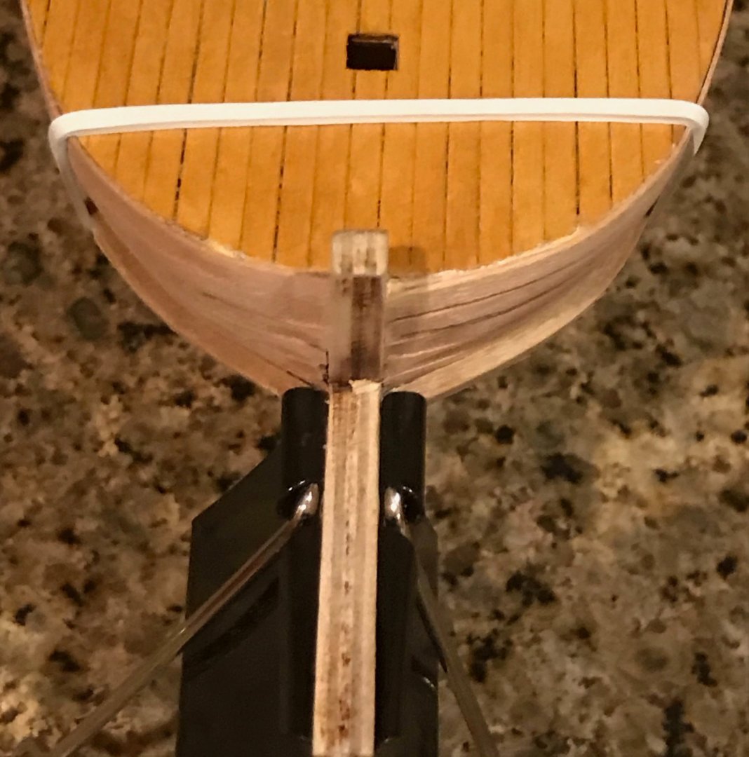
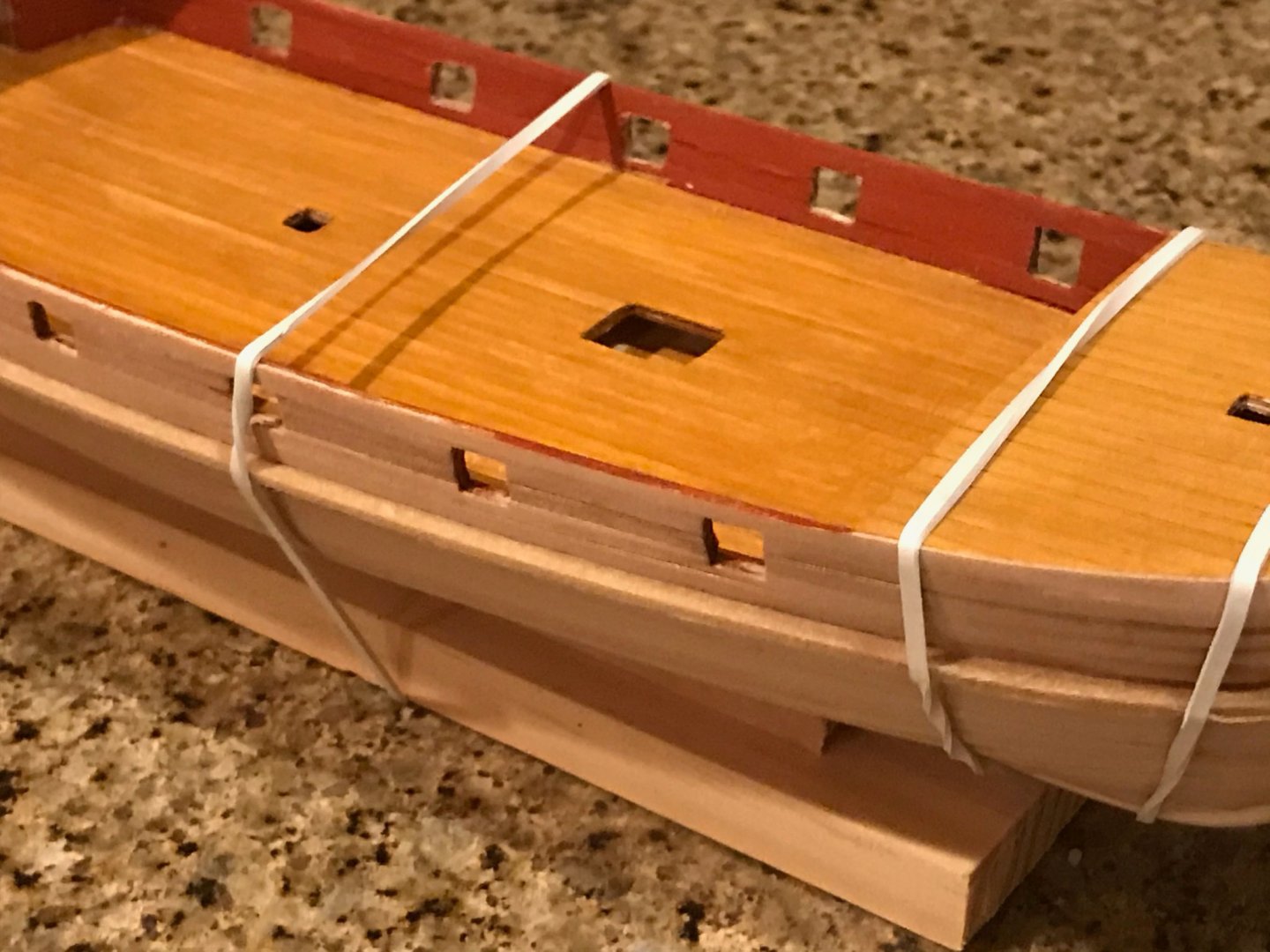
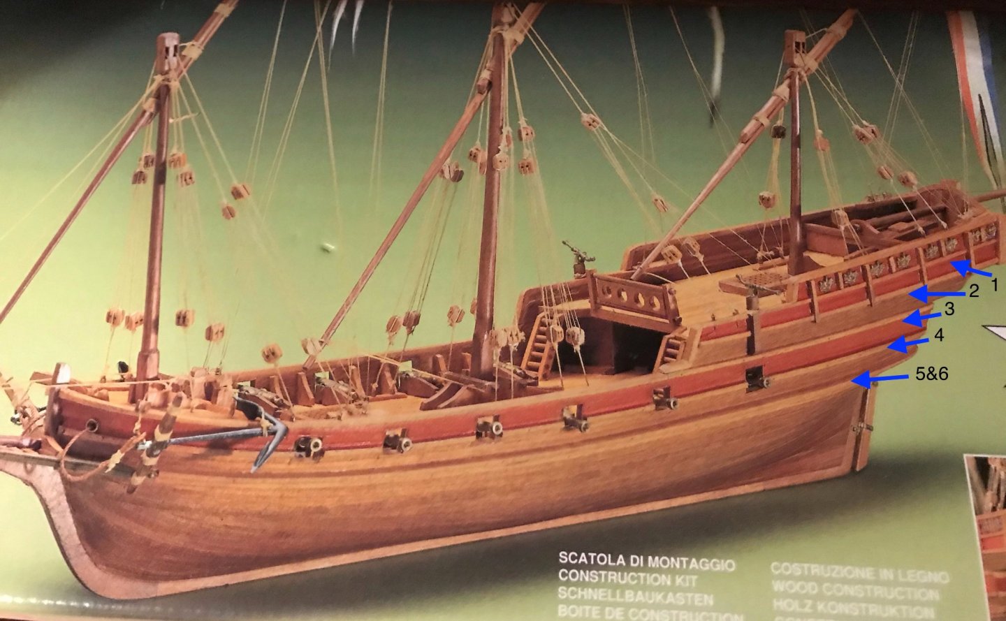
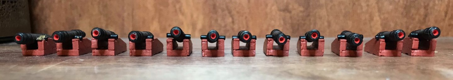
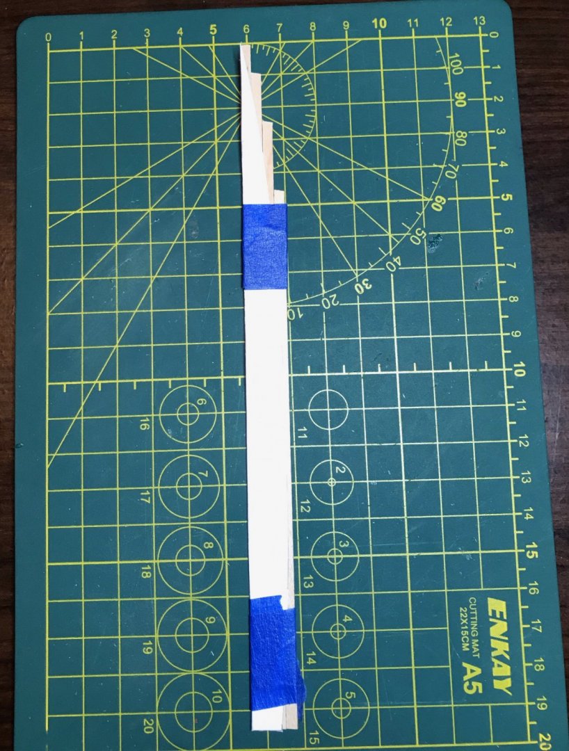
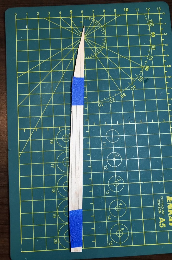
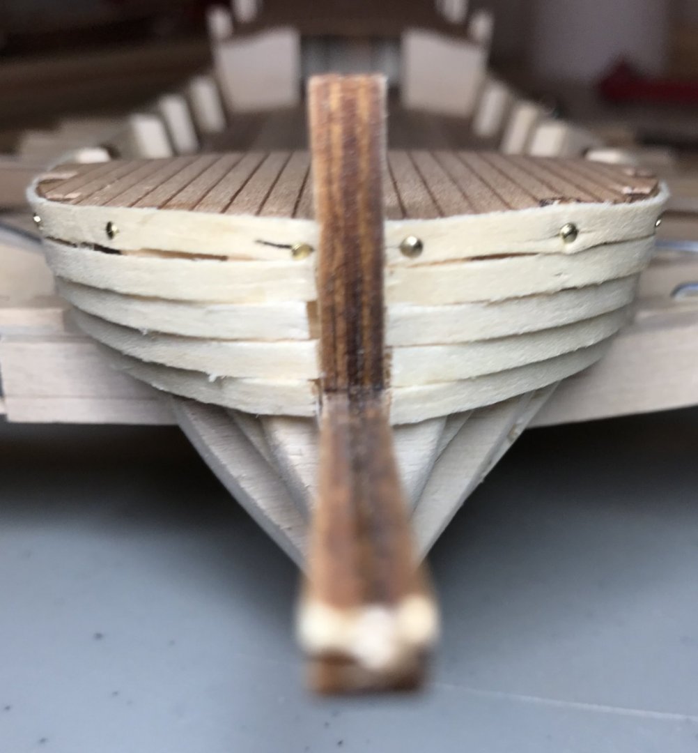
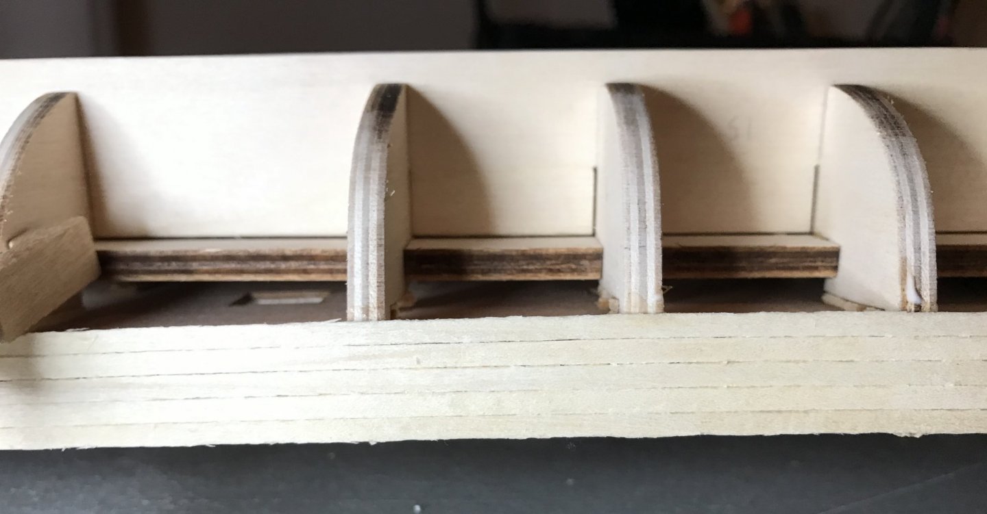
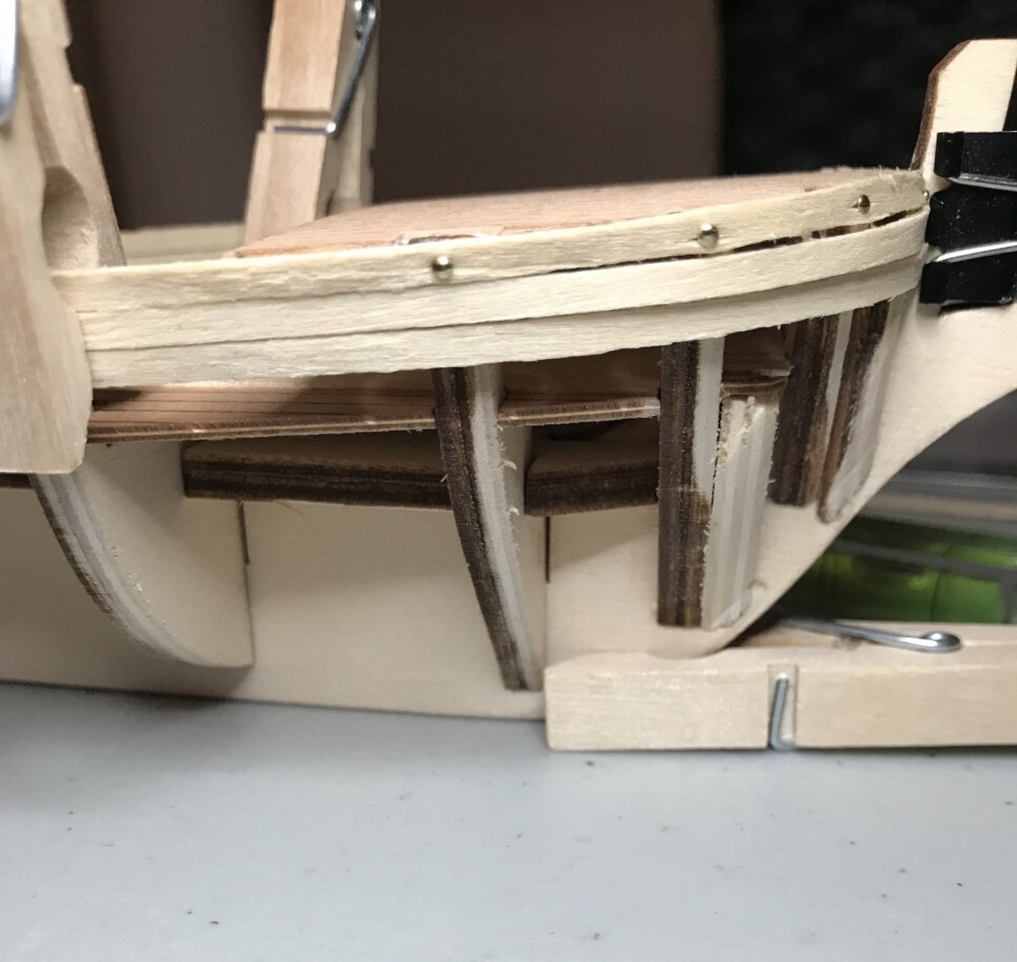
I was able to put in some good time on the xebec over the last few days. I planked the stern, then sanded the hull. I've also been plugging away at the cannon, installing the brass brackets and rivets. This has been a really tedious task and I can't help but think there must be a better way of doing it. Essentially, I glue the barrel into place, checking the angle against the gunport. Then I glue the bracket into place. A day or so later, I drill out holes for the rivets. Somehow, I always manage to detach the brackets in that process. I'm using an .8mm drill bit, since my .6mm bit is too small for the pins and my 1mm bit is too big for the holes in the bracket. Once the holes are drilled, I clean up the dried glue from the previous day, dab in a little bit of fresh glue and replace the brackets. Then I snip off the tops some pins and work them into the holes using the tip of my Exacto knife (the dull side, not the blade). That last step always seems to take a lot of tries before I get the pin to slide into place. The level of concentration needed is enough that I can usually do one or two before needing a break (though that would probably be better if I had one of those stand mounted magnifying glasses!). I can't imagine how some of you get through this step on more heavily armed warships! As you can see in the photo, seven down, five to go (one of which has a wonky brackets that need to be straightened!). I'm still holding off on the section between the aft-deck and the stern transom, though I think I've come up with a plan for it. In the meantime, I'm working on some of the trim for the hull. As you can see in the photo on the cover of the box, there are six horizontal pieces of trim and several vertical pieces. Some of the horizontal ones are basically extensions of the gunwales. For my own reference, I've numbered the horizontal pieces. All of them are 2x2mm limewood, except for #5, which is 2x3. Piece #5 sits on top of piece #6 and curves laterally along the side of the ship. I decided to start by fitting pieces #5 and 6. When my usual strategy of soaking wood in hot water wasn't sufficient to bend #5, I knew I needed to try something different. Since the kit comes with more 2x2 limewood than 2x3, I figured I ought to experiment on #6 first. After a lot of research on MSW, I convinced my daughter to loan me her curling iron. It took a little bit of experimenting—and only one piece of broken wood!—but I managed to get the hang of it. I had read plenty of advice to not do it all in one go, so ended up curving it in three stages. For the first two, I periodically dipped the wood in water and applied the curling iron with just enough pressure to get some curve. (The first two photos, with the curling iron, show the progress after each of these stages.) After two rounds of that, I was able to secure the to pieces to the hull and, with a bit more encouragement from the curling iron, I achieved an almost perfect fit. Tomorrow, I'll come back and clean things up, then get started on bending the 2x3 pieces. 5


- 79 replies
-
- 1
-

-
- sergal
- sciabecco francese
- (and 1 more)
-
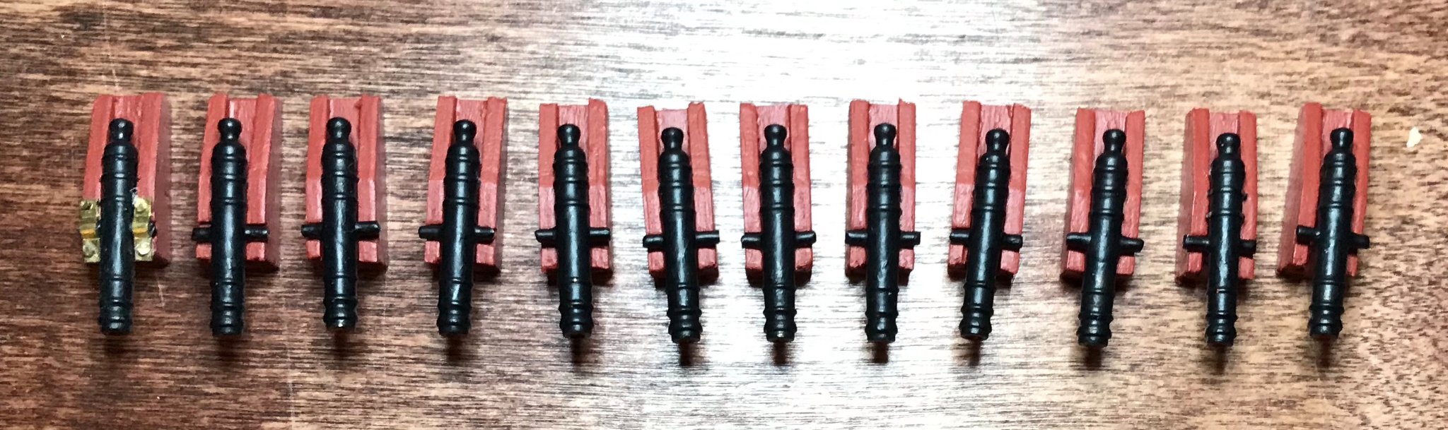
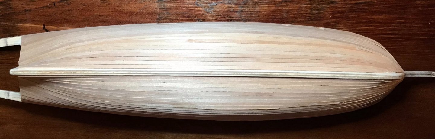
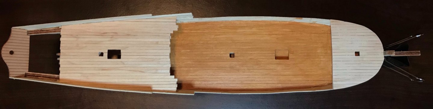
It's been a stressful week and I find working on ships is a fantastic stress-buster...so lots of progress happening here! The big excitement was laying the last plank on the hull! It's certainly not perfect and still needs to be sanded down, but it already looks a lot better than the first layer. My skills definitely improved as I went along. The photos are of the starboard side and a shot from below. I still need to plank the stern, but this was the big landmark for me. I have also painted the interior bulwarks and stern transom in red ochre. I'm trying to paint this in the style of the xebecs that were used in the French navy in the 1750s. Jean Boudriot seems to be the expert on this. While I haven't managed to get my hands on his work yet, I have found some helpful summaries on various discussion boards. Roland Portanier's MA thesis, "The Lost Art of Naval Decoration in 18th Century French Canada," has also been immensely helpful, thanks to a great footnote summary (p. 44, fn 137) and reproductions of two figures from Boudriot's Le vaisseau de 74 canons (pp. 121–122). Not a great photo, but you get the idea at least. Finally, I've mostly finished up the cannon. The carriages are assembled—no wheels here—and everything is painted (red ochre for the carriages, matte black for the barrels, and red for the bores. When I made a test cannon a while back, I discovered that it was essential to get some drill bits smaller then 1mm. Those will be arriving on my doorstep tomorrow, so this weekend I'll get the brass hardware attached to the rest of them. Next steps: sand the hull, plank the stern, and figure out how to successfully assemble everything that goes between the end of the aft-deck and the stern transom. (I took a stab at that one evening this week...it did not go well...)

- 79 replies
-
- 2
-
-
- sergal
- sciabecco francese
- (and 1 more)
-
Thanks, Jaager and Druxey. I'm still a real novice in this hobby, so appreciate the insights. So far, so good with the finished models, but I'll be keeping an eye on them.
-
[Note: I wasn't sure where exactly to post this. Moderators, please move it if I have put it in the wrong place.] We just moved to a new house and have been acutely aware of how much drier the air is here—relative humidity percentage is consistently in the 30s, where it was usually between 45 and 55% at the old place. Now that my current project and tools are unpacked, I was able to get some work done this morning. After placing a soaked plank on the hull, I could watch it dry (within 10 minutes that plank was no longer visibly wet!). Unfortunately, when I was cutting a plank of 2x3 limewood, I discovered that the drier air has made the wood significantly more brittle than I'm used to. So, this raises a question for me: is there an ideal relative humidity for working with wood? I'd also appreciate any tips on working with wood in a drier climate. Thanks in advance!
-
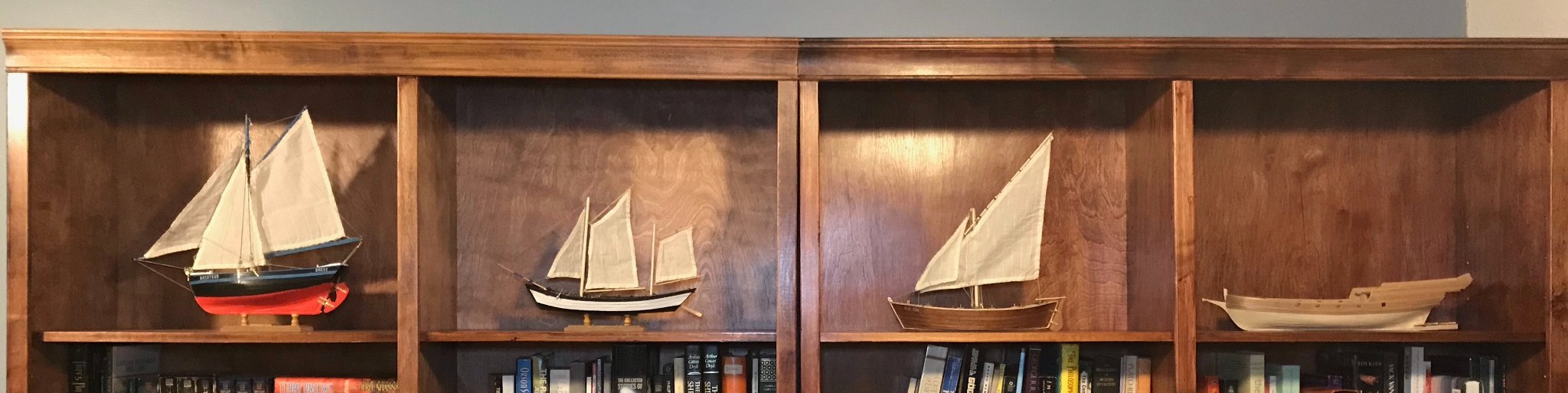
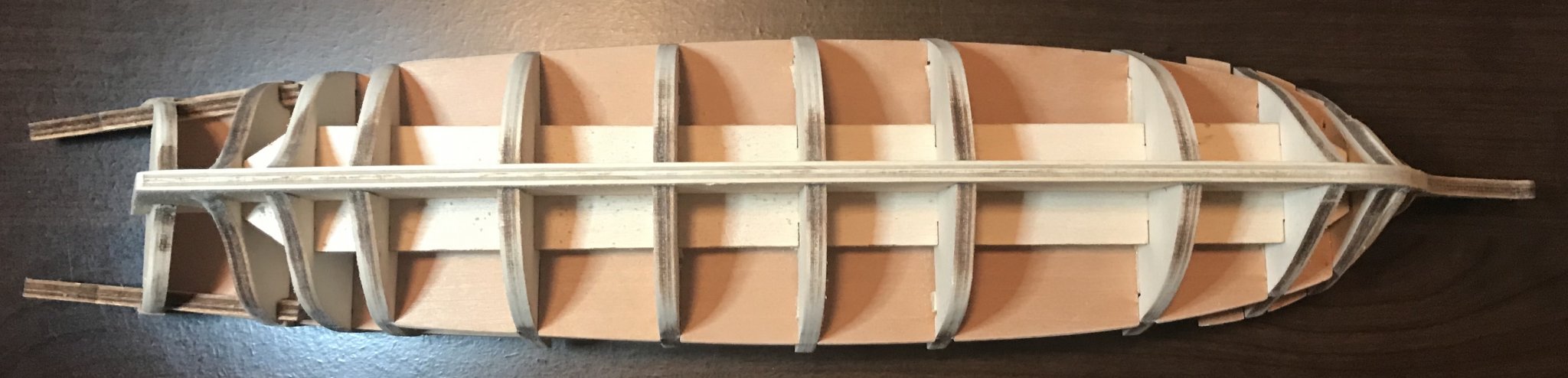
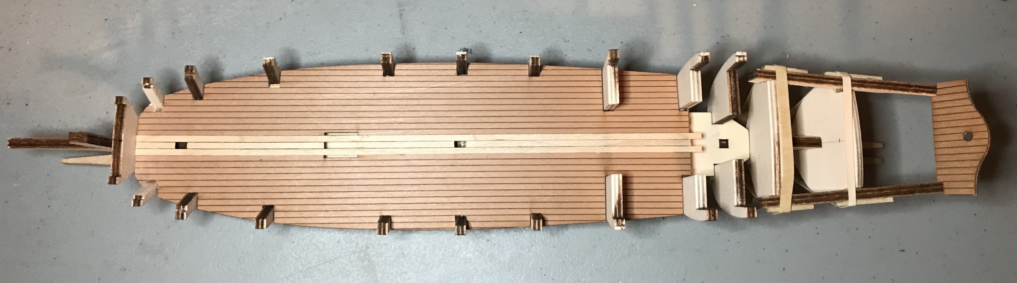
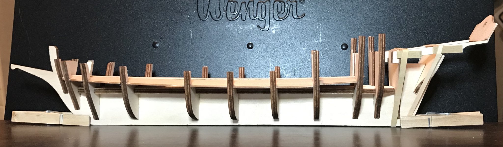
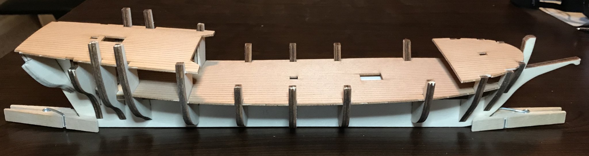
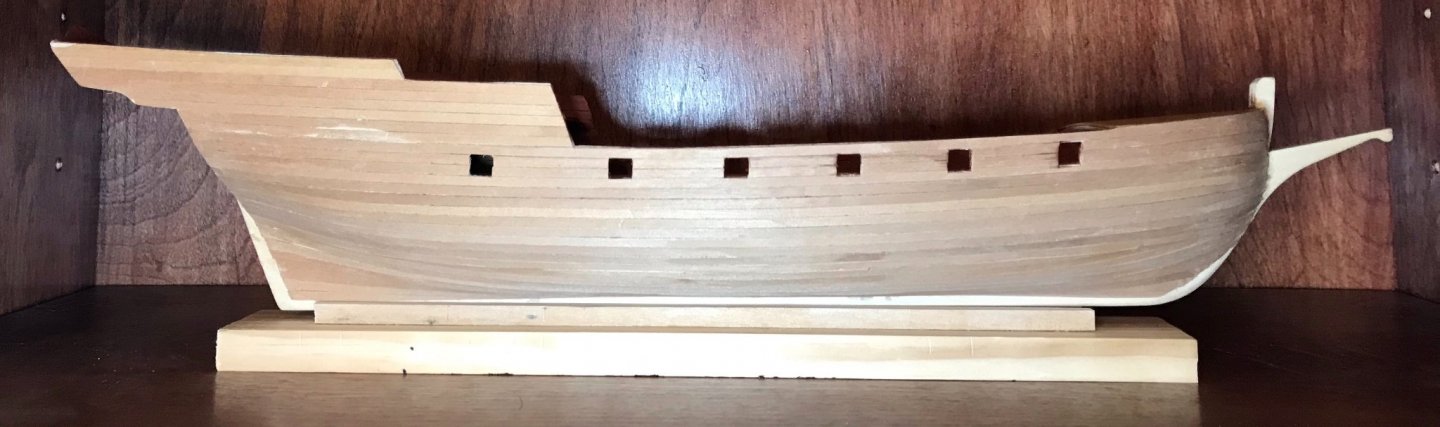
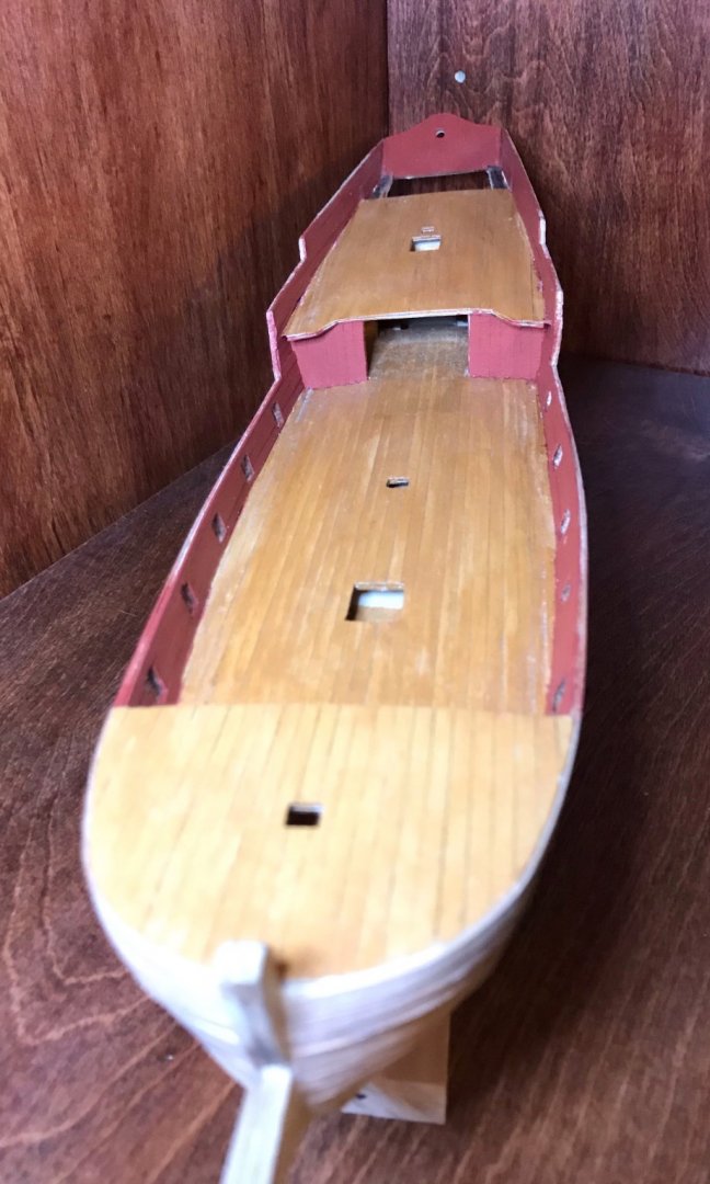
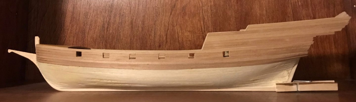
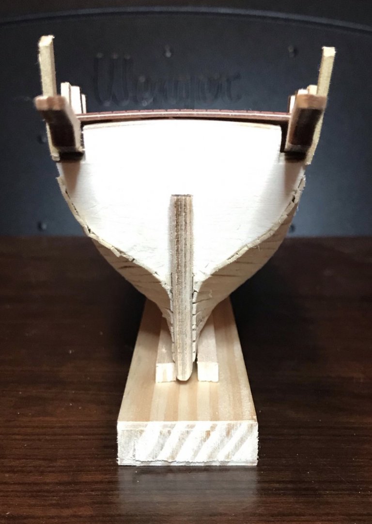
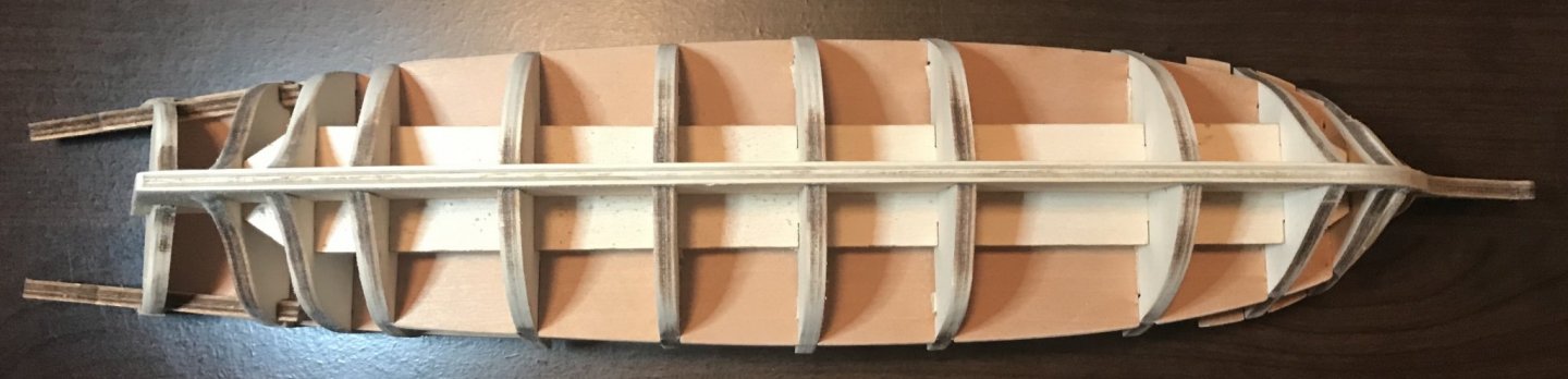
This time a month has passed since my last update! But what a month, highlighted by purchasing and moving in to our new house! I still have a lot of boxes to unpack in my office space, but I did get to the point last night of being able to pull out some of my tools and do some work on the xebec. So, a quick update on what I've done over the last few weeks: I cleaned up the fore- and aft-decks, then stained them. I lined the façade of the parapet and the interior of the bulwarks with walnut planks. Some really fussy work there! I ended up making paper stencils of the two sides of the façade, then trimmed the planks to match and maneuvered them into place. The interior lining of bulwarks needed a significant amount of careful trimming to follow the curve of the main deck and to fit around the fore- and aft-decks. The slope of the aft-deck is also different than the slope of the planks in the lining, so it was a bit of work to get those to fit snugly. I started laying the second layer of planks on the hull. This didn't go as smoothly as it probably should have...I ended up applying three to each side and then removing them. The second attempt has gone much better. While I realize that I should have finished the whole hull first, there were a few things that I wanted to make sure were done before everything went into boxes for the move. So, I've also done the outer layer of the parapet and cut out the gunports. (Gunports haven't been filed yet, so they look a little funky.) Last night, I cleaned up the tops of the bulwarks and cut the angles between the different levels of the bulwarks. Note the difference in profile from the photos in the last post to this one—a much sharper look! I also began cleaning up the interior planking on the stern transom; still some work to do on that, though it's starting to take shape. Next step is to sand down the excess planking around the stern transom and the longerons. Then, once a few more boxes are unpacked, I'll be able to resume work on the hull. The photos are an overhead shot on my worktable, then front and side shots on the shelf where it will ultimately be displayed. Then, just for fun, a shot of the top shelves of my bookcases, where my completed ship models are awaiting this one!

- 79 replies
-
- 1
-
-
- sergal
- sciabecco francese
- (and 1 more)
-
Thanks, Hugo! There aren't many build logs of this kit out there, so I hope you'll create one, too. I see we're walking some of the same paths, since my first build was also the Bon Retour!
- 12 replies
-
- 1
-
-
- la provençale
- artesania latina
- (and 1 more)
-
Glad to hear that you've been safe from the fires so far, Bob! I hope you can stay that way! As I was reading through some of your log, I noticed your comment about struggling to wrap your head around a gaff rig. I had the same challenge when I built the Bon Retour (my first kit!), which is also from Artesania Latina and also had unclear rigging diagrams. In the end, I found a couple YouTube videos that were much more helpful. Based on what I saw in these, I was able to install rigging that actually worked correctly (meaning that I was able to hoist the gaff and boom, and to use the rigging to adjust them to get the right tension on the sail). Here are the links, in hopes that they'll be helpful for you: "Handling a Gaff Rig" by How to Sail Oceans and "Gaff Rig - How We Hoist Our Gaff Rig" by Living with the Tide.
-
Almost a week since I last posted! It's been a busy one, though I've managed to squeeze in some work on the xebec. The first big task from last week was to lay down the first layer of planks on the parapet's exterior. There's still some trimming to do on the front ends of those, but since they follow a staircase, I'm going to wait on that until I have a better idea of how the staircase fits. However, the ship's true profile is really starting to emerge! Next step on that front will be to map out and cut the gunports. (Note: I had an issue of poor construction with my slip, so I need to remake that.) A note for others who might make this kit: The diagrams indicate that you should attach the transom when you affix the bulwarks and longerons. I did, though a bit of guesswork was involved. However, with only minimal points of contact, it fell off. This is why you will notice it in my post from September 6, but then it disappeared until this post. Based on my experience, I recommend using the stern to align the longerons when you attach those, but not to worry about gluing it at that point. Instead, glue it into place at this stage, when you can rely on the side planks for extra support and for positioning it at the correct angle. Most of my work in the last week has been devoted to the three decks, which are all in slightly different stages. There are two coats of stain on the main deck, though I need to sand that down and try to get it more even. (The camera angles may introduce some curvature, but the lighting also make the stain look better than it actually is.) I've opted for an oak stain to contrast with the walnut that will line the bulwarks and hull. The foredeck has been planked and sanded (though the photo revealed one spot that needs to be filed down a bit better); I'll be staining that later this week. This evening I finished planking the aftdeck; plenty of trimming/filing and sanding to do there once the glue dries.

- 79 replies
-
- 2
-
-
- sergal
- sciabecco francese
- (and 1 more)
-
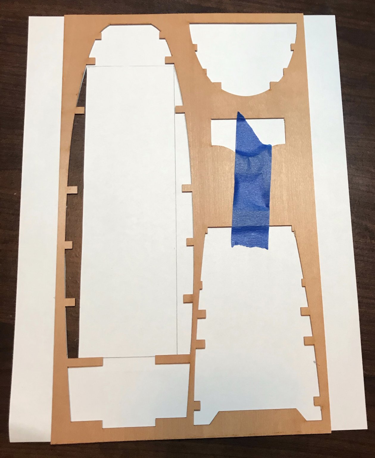
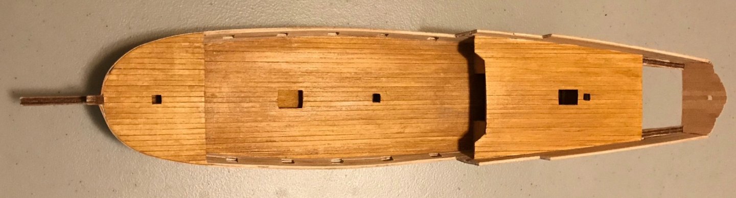
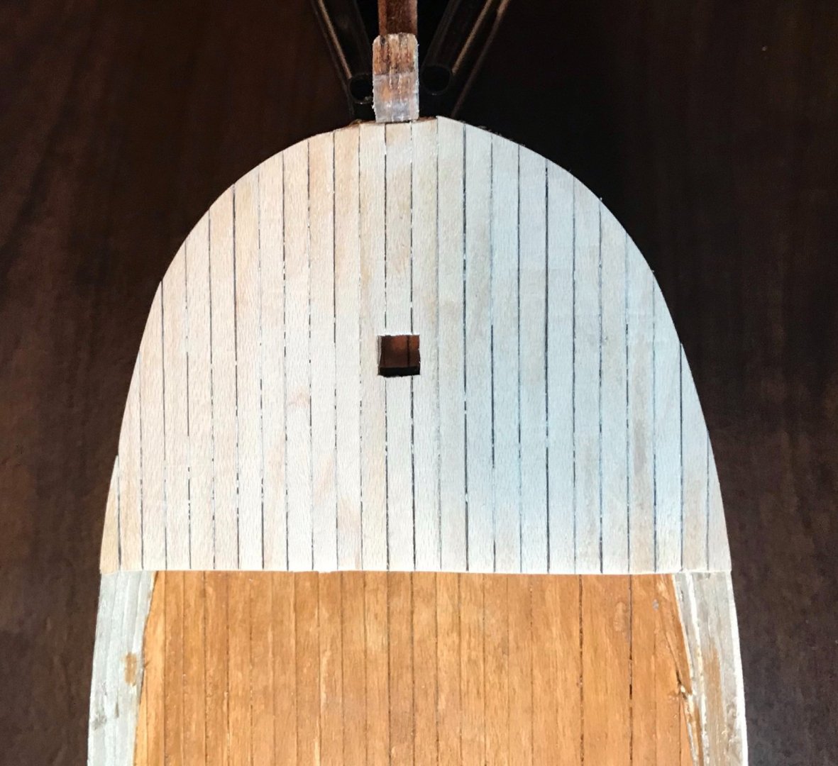
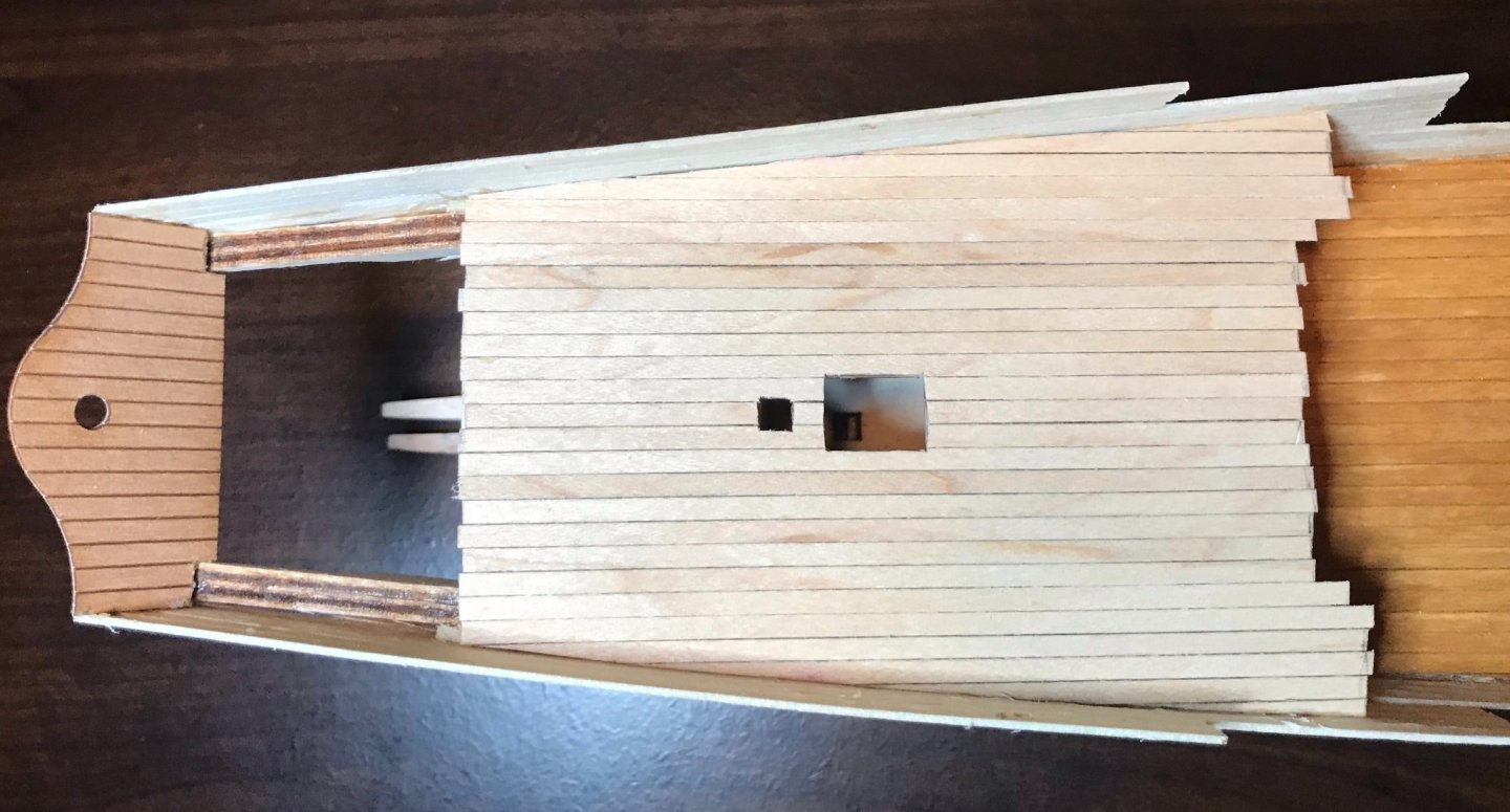
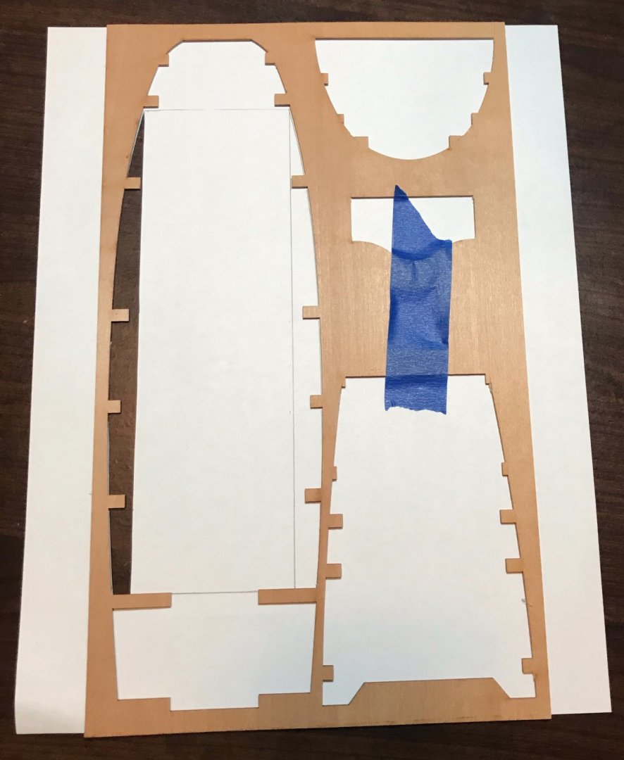
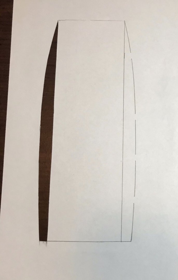
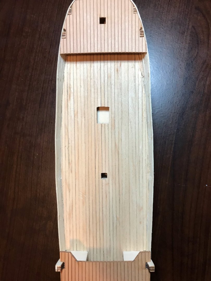
Finished planking the main deck tonight. As I mentioned above, this was done in two stages, since significant portions of the main deck are inaccessible once the fore- and aftdecks are installed. Because of that, I'd taken care of the middle part, the easy part since everything ran straight from bulwark #1 to bulwark #9. The edges, however, posed more of a challenge due to the overhang of the fore- and aftdecks and the curvature on the sides. Using a technique I picked up while working on the Bon Retour, I used a paper stencil to get the fit as tight as I could. (For reference, see Invictaag's Bon Retour build log on BrexitModeller; I planked the Bon Retour's deck before installing the bulwarks, so this my first time using this technique.) The photos don't capture all of the steps, but they should give you a good idea. First, I used the plywood sheet to trace the open section of the main deck. I used a little bit of painter's tape to keep the plywood from sliding around. In order to get the straight vertical lines, I measured at each bulwark the gap between the sides and the planks that I'd already laid; then I just used a ruler to connect the dots. After cutting out the stencil, I checked it against the deck to make sure everything was still lined up well. (I didn't start taking photos until I was sure this was going to work, so the first stencil is already cut out in these two photos). Next, I trimmed four planks to a size that would generously accommodate the curve. After securing the planks to each other and the stencil using painter's tape, I trimmed off the excess. Then I laid the whole block in to check the fit, fine-tuning the trimming as necessary. The first photo here is stencil side up before trimming the excess; the second has the planks up after trimming (but before fine-tuning...that curve in the second photo isn't smooth yet!). And two shots at the end, one overhead and one close-up of the port side (the side that looks better...). There's still sanding to do once the glue dries, but I'm pleased with how the deck is looking so far!
- 79 replies
-
- 2
-
-
- sergal
- sciabecco francese
- (and 1 more)
-
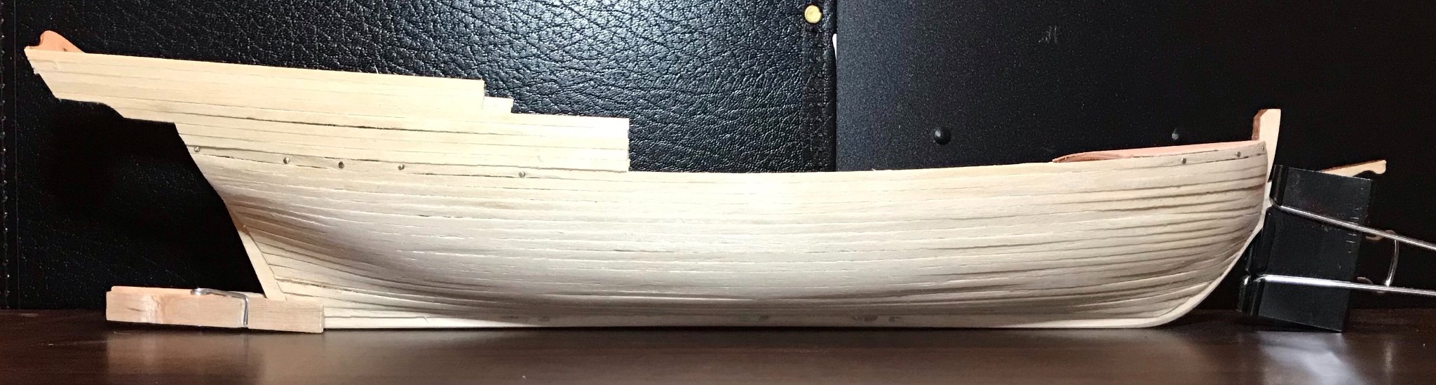
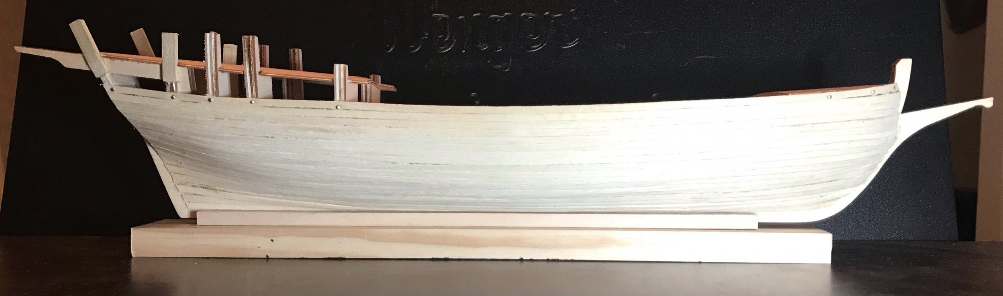
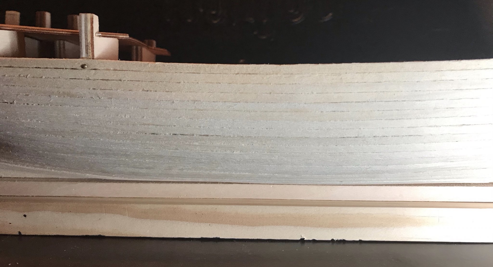
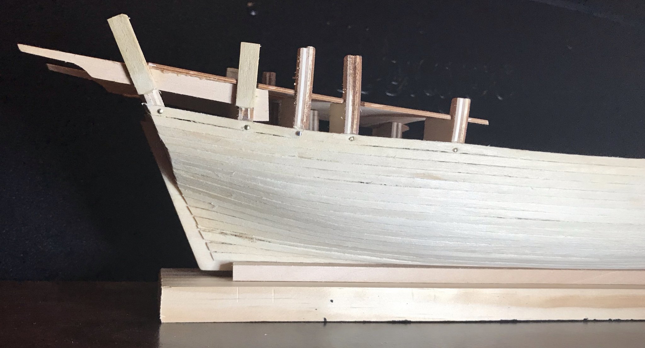
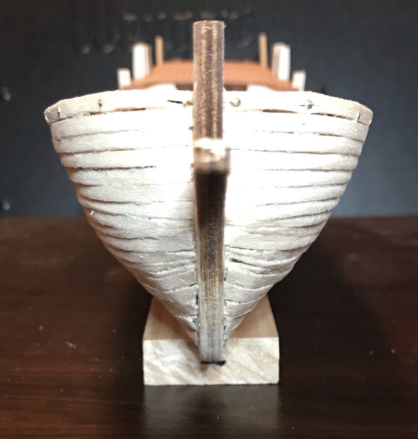
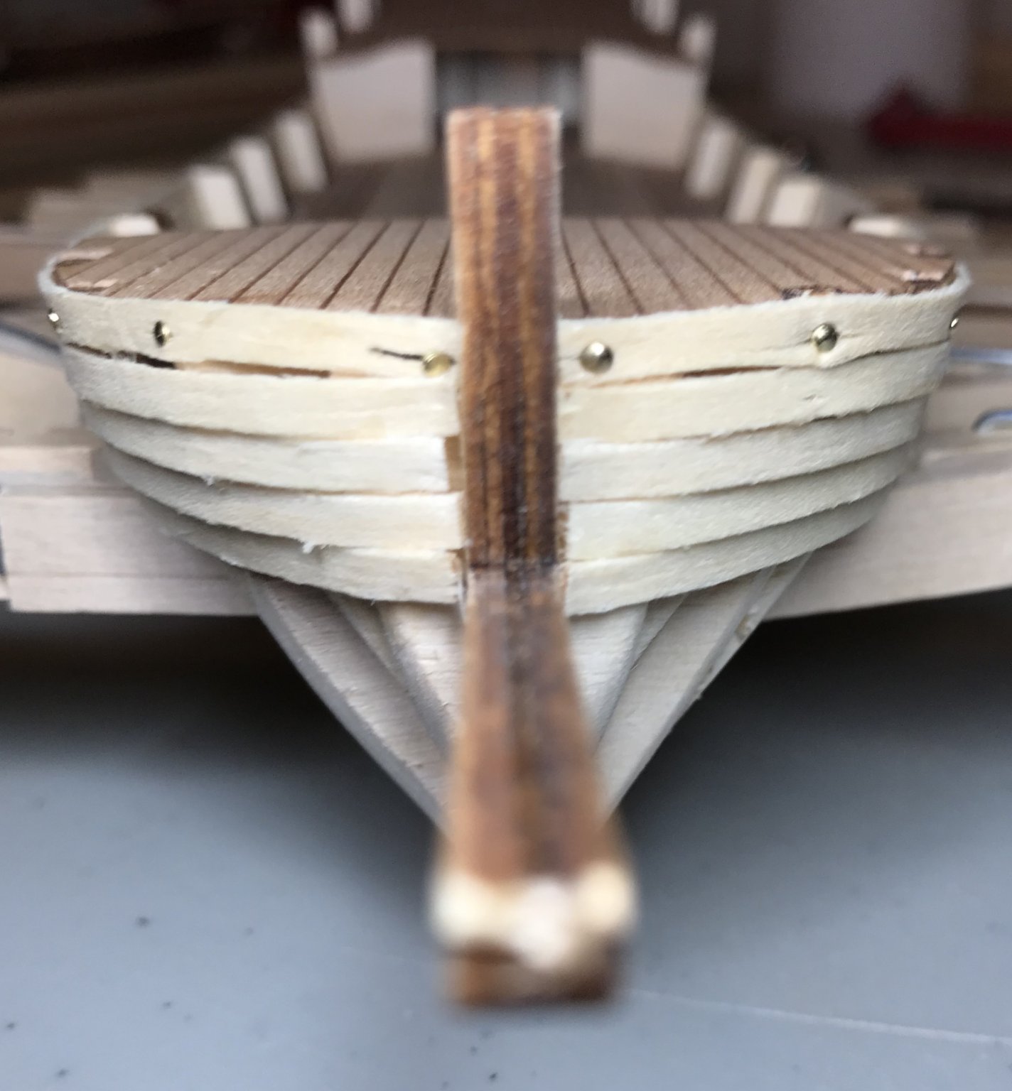
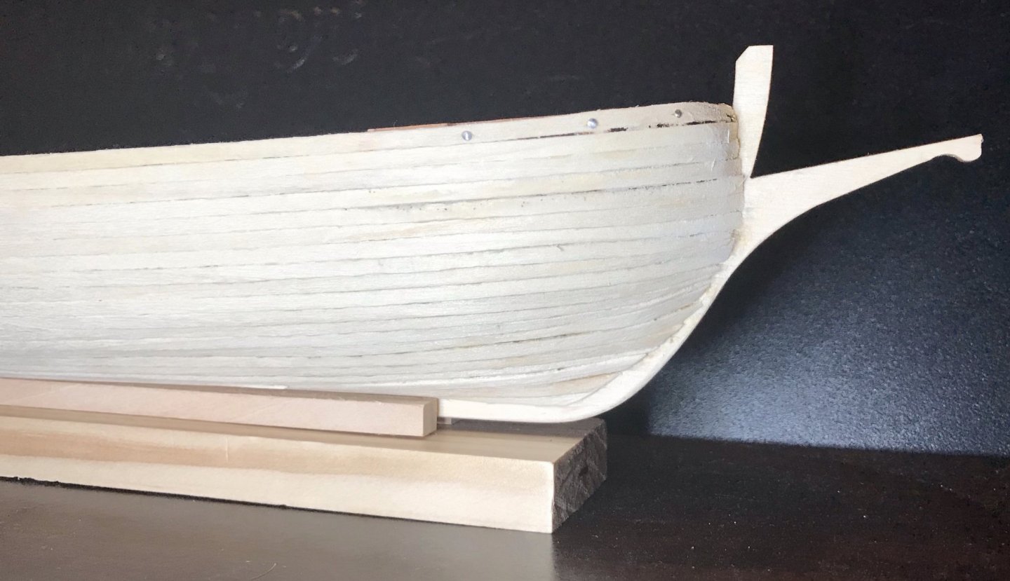
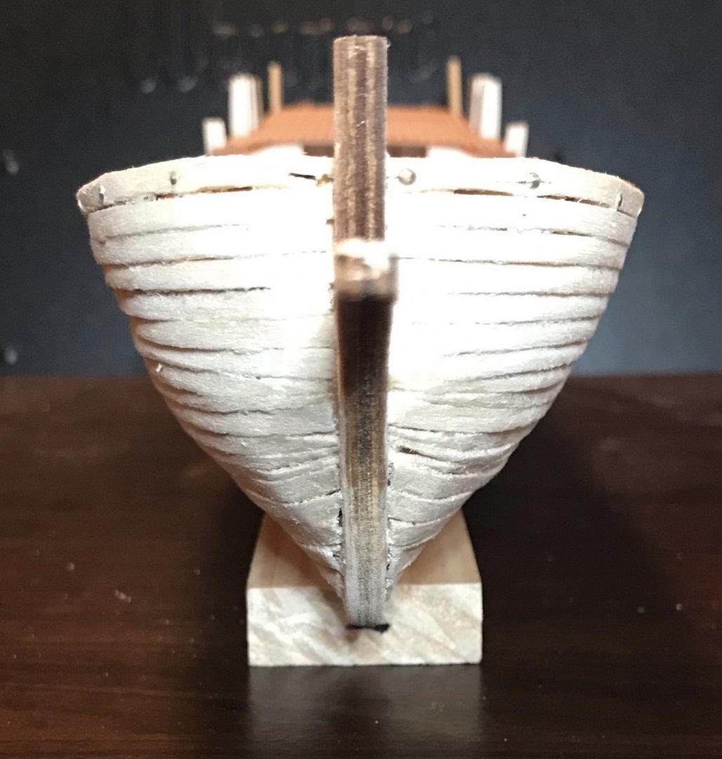
Slow and steady progress on the hull over the past week and a half, but tonight I glued in the last two planks of the first layer. I've done a bit of sanding, but have a ways to go to smooth everything out. I'm mostly satisfied with the work I've done, though I would hardly call it perfect. The bow still has a bit of a clinker effect that I'm hoping I can sand down. The stern hasn't been sanded or cleaned up at all yet, so it still looks a bit raggedy where I trimmed the planks. The planks between the maximum curve and keel amidships have some gaps that I've filled with PVA glue and sawdust (not clearly visible in the photos). I also built a slip for the boat to sit in while I work on it. The kit provides a 6x6x500 piece of limewood for just this purpose. After cutting it in half, I attached the two pieces to a random piece of 3/4"x2" that I had sitting around from another project. Next steps: I've trimmed the tops of the bulwark frames from the main deck and so need to finish planking it. Then I'll plank the sides of the parapet and add deck planking to the fore- and aft-decks. Photos are a full shot from the starboard side, then three details of stern, midship, and bow. Finally, two shots from straight ahead and straight behind.


- 79 replies
-
- 4
-
-
- sergal
- sciabecco francese
- (and 1 more)
-
Thanks for sharing that, Bob, and thanks to glbarlow for the beautifully illustrated guide! I think the bow is the key spot where I need some more practice. After that first plank, the others have gone on better, though there's a bit of an unintended clinkering effect that will have to be smoothed out and a slight imbalance that I'll be paying attention to as soon as I reach the ones that are tapered. Although I definitely need to keep building my skills, I can definitely see improvement compared to my first ship, the Bon Retour, which had a single-planked hull and which needed a lot of help from woodfiller to smooth out the hull. However, once I get past the curves of the bow, everything's looking good to me.
- 79 replies
-
- 1
-
-
- sergal
- sciabecco francese
- (and 1 more)
-
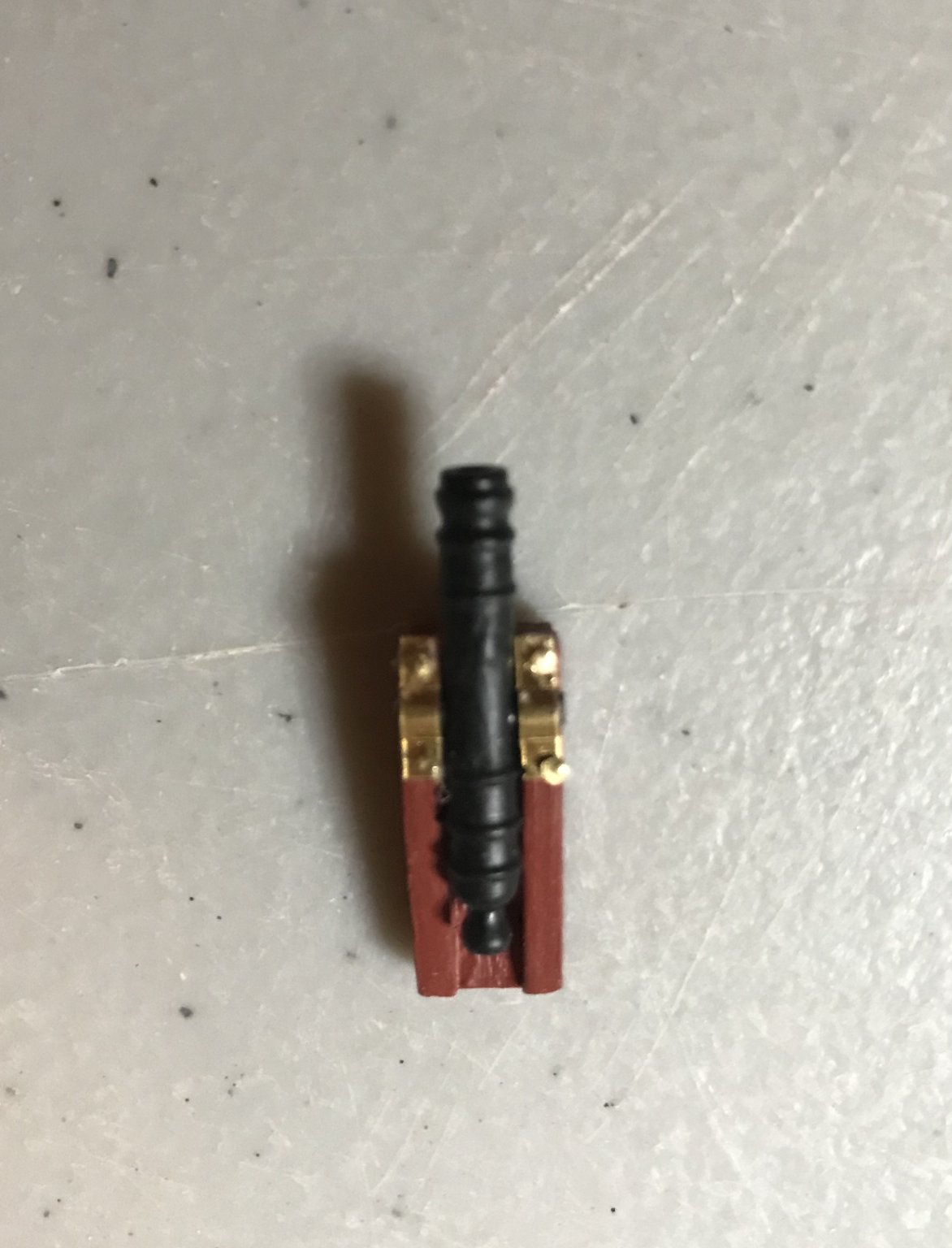
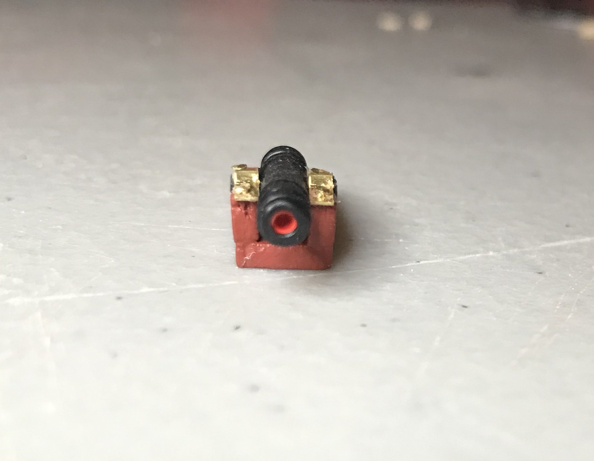
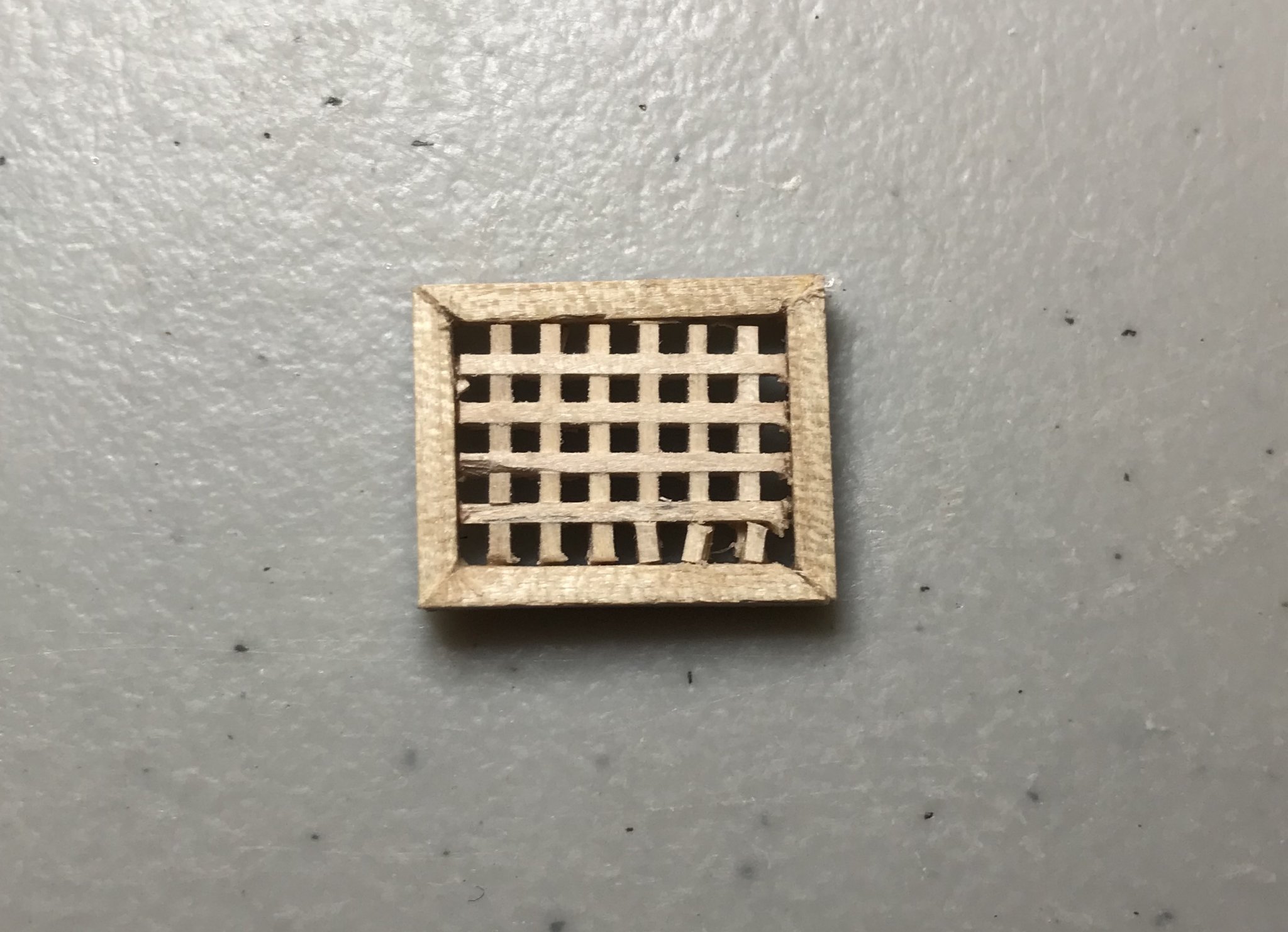
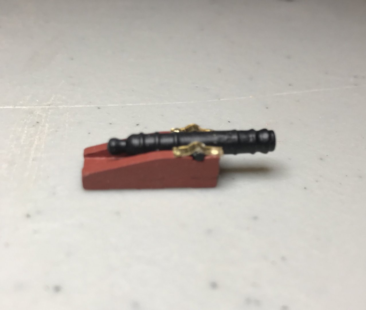
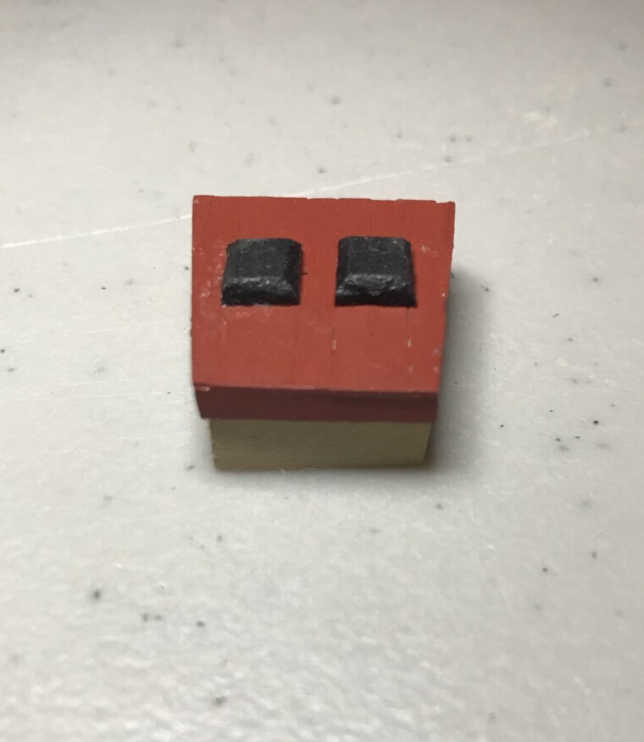
I've started planking the hull, which I find to be one of those hurry-up-and-wait kind of processes. I soak two planks at a time in hot water, then clip them into place. Once they've dried fully, I glue them into place. And once that's dried, repeat. I end up doing one plank on each side per day. So, there are now three on each side! That process has gone just okay. Since this is my first ship with a double-planked hull, I tried using nails to keep the first plank in place, as I've seen many others do. My technique for that is...not great. After breaking two planks I gave up on that and went back to just clipping them into place. Right now the planks I have in are looking okay, and they generally get better as you go further astern. There are some gaps that I thought I had managed to avoid, and when I took this close-up photo of the starboard bow, I noticed that the boards weren't laying as uniformly flat as I thought they were. Thank goodness for sanding and wood filler, I guess! Since the hull planking is such a slow process, I've started looking ahead to see what I can do about with all of the pieces that I'll need to fabricate. I've started with several items that I'm doing for the first time and I think they're turning out okay. I'll have plenty more opportunities to practice those with this ship! First up is the rudder well and its cover. The last couple inches of the parapet are a significant puzzle to me right now. Since the base of the rudder well cover is a pre-cut piece, I'm working outward from that. The cover is planked with deck planks (.5x3 limewood), then a lip is added on three sides with the same planks. I'm trying to follow the paint scheme for the French navy in the era of Louis XV (when xebecs were first introduced to that navy), so fixtures like this are all going to be painted in red ochre. On top of the cover are two guides for the sternsprit. In the photo its sitting on the frame of the rudder well; I cut those three pieces out of 2x8 limewood the sanded them, so they are lined up under the cover while the glue dries. Once that's set, I can start to measure out the frame for this section, in preparation for adding grating in one part and dowels in the other. From here on out, the pictures are extreme close-ups at the limit of what my phone can do...apologies for the poor quality of them. This is the largest piece in this set of photos and its only about 21x25mm. I'll have to track down my daughter's iPhone telephoto lens at some point, so I can get some better shots as work progresses. In addition to the sternmost part of the parapet, both hatch covers are made of grating. None of my previous kits had any of that, so this shot of the aft hatch cover is my first effort. I sanded the 45º angles in the corners of the frame to match the plans; this was also different than my previous kits and required a great deal of patience to get everything to fit. Overall, could definitely be better. Once the glue dries, I'm hoping that sanding will help even things out more. Then some red ochre paint. All of my previous kits were fishing boats, so this also represents my first time building cannon. Before cutting out gun ports, I wanted to make sure I had one cannon built to use as a guide. The carriage consists of three pre-cut pieces that fit together like a glove. The cannons arrive in brass...a couple with tarnish that will need to be cleaned up. The axle is also pre-cut, though it's really snug as it slides through the pre-drilled hole in the cannon. That much goes together pretty easily. The brackets and pins? Uff da. It's a similar challenge to putting nails in the brackets on a rudder...but with much less surface area to catch dropped pins. Since my smallest drill bit is 1mm and the sides of the carriage are also about 1mm, I decided to drive in pilot holes with pins. After gluing the bracket in place over the pilot holes, I used a toothpick to dab in a small drop of glue. I cut the head off of a pin with as little of the post as possible, then used the tip of my Exacto knife to maneuver each pinhead into its pilot hole. Of course, I painted before assembly: red ochre for the carriage, bulwark gun red for the barrel, and iron black for the cannon. For a first attempt, I'm pretty pleased. Only eleven more to go!


- 79 replies
-
- 1
-
-
- sergal
- sciabecco francese
- (and 1 more)
-
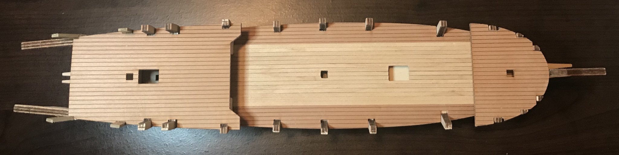
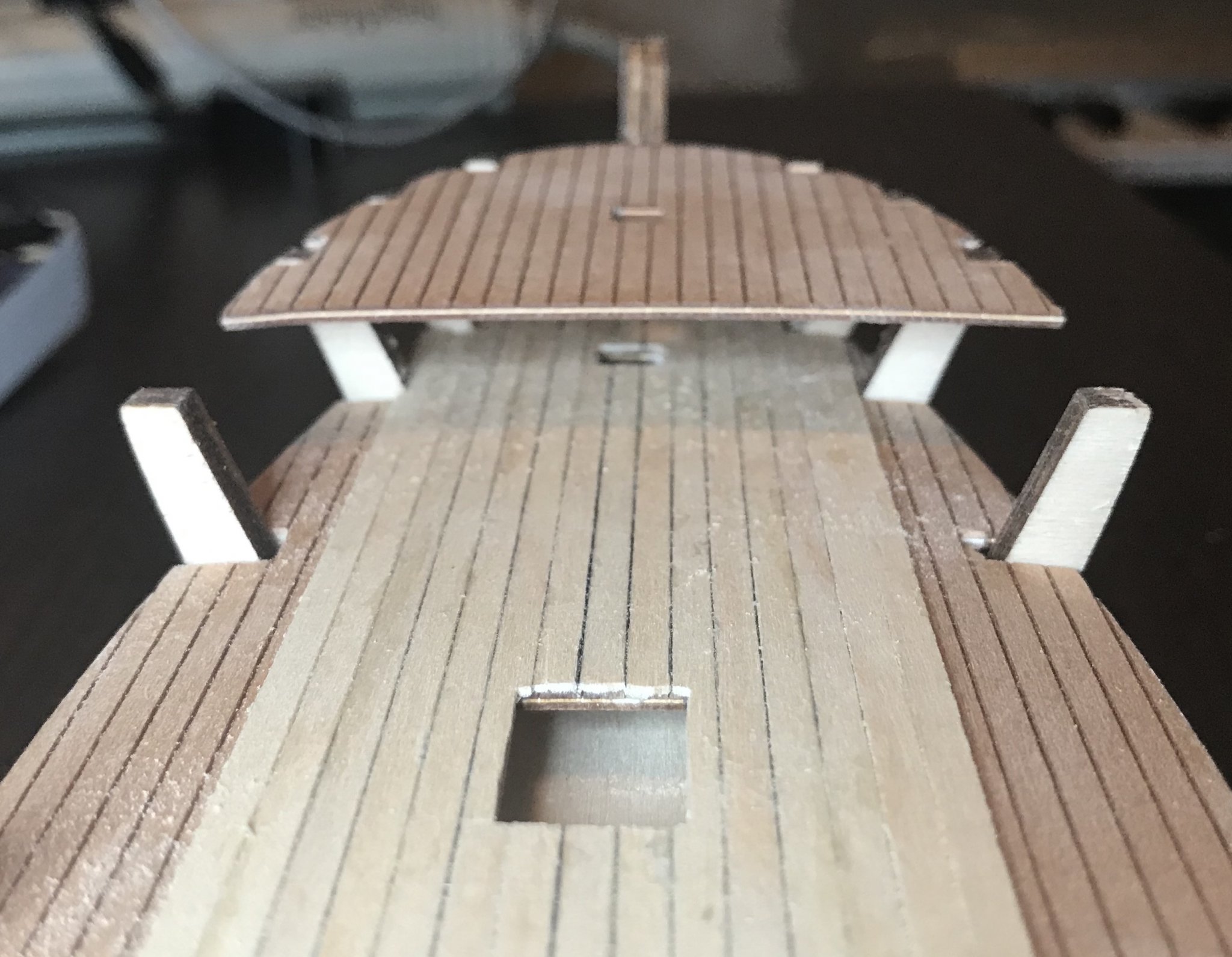
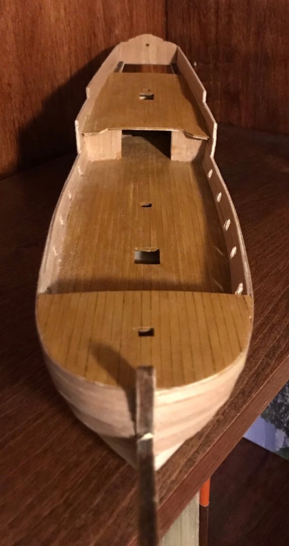
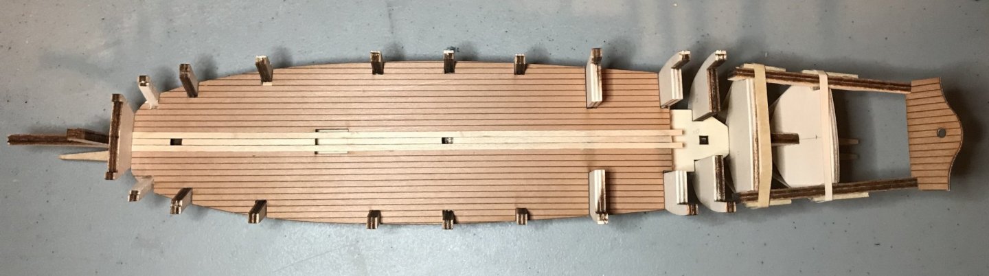
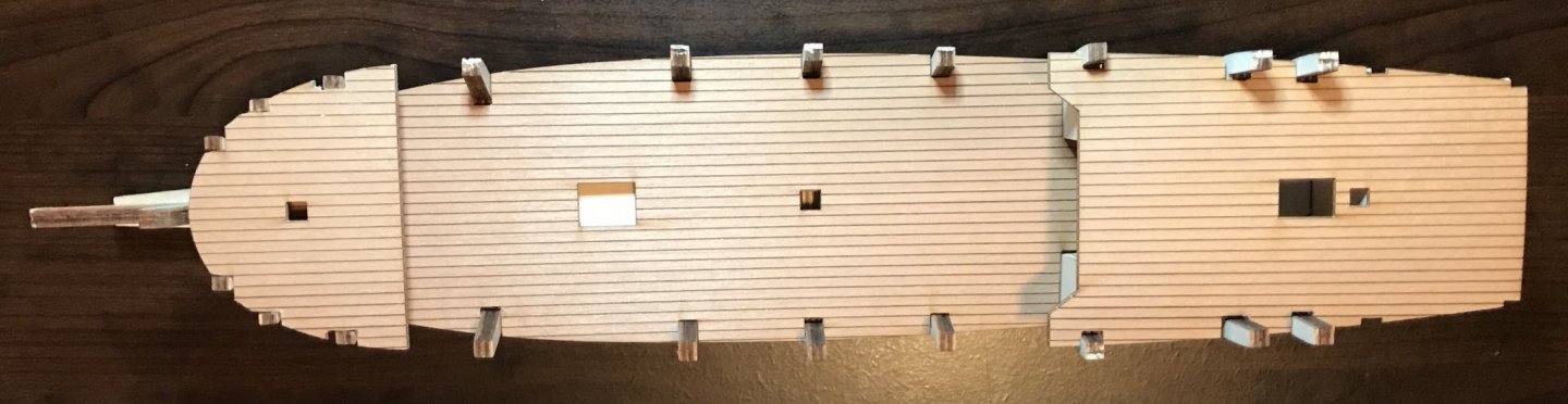
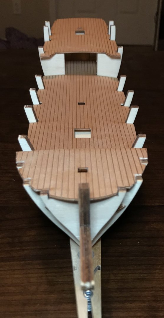
Feeling a little more settled with this project now. Still intimidated by how much fabrication there will be later on, but I'm keeping focused on going one step at a time. I've now attached the fore- and aftdecks. These shots show some of the reasons that considering sequencing is so important in this kit. In the overhead shot, the fore- and aftdecks both overlap the main deck by a significant amount. The next photo is a lower-angle shot that looks at the main deck planking that extends for a bit more than 2 inches under the foredeck. The third photo is a low-angle shot looking toward the stern. There, the main deck planking extends about an inch or so under the aftdeck, though much of that (10 planks worth) is between the walls formed by bulwarks #8 and 9. The remaining deck planks will be added once I've planked the hull and trimmed the posts off of the bulwarks. Forgive the sawdust...I took these photos at a time when I couldn't run the shop vac to clean up! I've also been sanding down the bulwarks in preparation for planking the hull. The lines feel very smooth! In the second photo, the two wedges closest to the front come with the kit. I've actually turned them 90º from what is indicated in the directions. This way, a little more of the stempost shows, as seems to be the case in many photos I've seen of xebec models. With sanding, everything flows smoothly from the stempost, over those wedges, to the first couple of bulwarks. I added the wedges between bulwarks #1 and 2—the gap between them is 5mm, so I just cut a couple of pieces of the 5mm plywood sheet from which the bulwarks were cut. Given the amount of rounding on the prow, I thought is was necessary to have just a bit more surface area for attaching the planks. In person, the apparent gap in the portside wedge is not as worrisome as it might look here. There's plenty of surface area to work with.


- 79 replies
-
- 1
-
-
- sergal
- sciabecco francese
- (and 1 more)
-
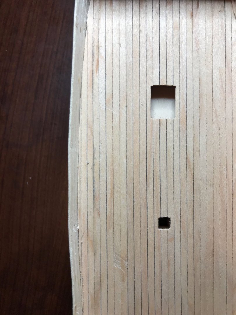
Plugged away at the xebec again this evening. Nothing much to show off, but I've finished the initial planking of the main deck (the middle 15 planks and those in the space between bulwarks #8 and 9). I was about to glue on the foredeck, when I realized I should first check the fit of the foremast. That mast sits at an angle and runs through both the foredeck and the maindeck. Once the foredeck is attached, there will no longer be any access to the hole in the maindeck, so that hole needs to be addressed first. In order to do that, I need to fabricate the bottom part of the foremast (which means sanding down the dowel and lining the bottom with walnut planks). Seems straightforward enough, right? Well, one thing led to another and now I'm feeling really intimidated. I knew this kit was a step up from my previous three—those were all beginner kits and this is advertised as advanced beginner. Before I started, I read through the steps and looked through the diagrams...but now I'm starting to realize just how big of a step up this ship will be, with lots of parts for me to fabricate. For some of those steps, I will need to pick up some new tools (though just today I inherited a bunch of tools from my father-in-law, so maybe that box will have what I need?). In addition to the fact that I'll be fabricating a lot of parts, I'm concerned that there are no measurements for 67 pieces of wood in those parts, so no way to budget any of the materials except for the ø4, ø5, and ø6 dowels and 2x6 limewood. I know those measurements will become more clear as things start to come together, but I hope I don't run out of materials since my stash of leftover wood from the previous kits is pretty limited! To calm myself and face the feeling of intimidation, I've now gone through the drawings very carefully and built a spreadsheet listing all the parts. I've also color-coded the diagrams, so it's easier to see what materials are needed in each step. Probably should have done this sooner, I suppose, but I had been planning to build the spreadsheet once I'd finished the hull and began turning my attention to the various features on the exterior and the deck. For those who might do this kit: be aware that the parts list is not organized by the parts, but rather by material. That list indicates the material and dimensions (for example, three 500mm ø4 dowels, sixty 1x3x500mm planks of limewood, etc.). The uses and dimensions for those materials are mostly indicated in the plans, but not the assembly instructions. While the parts list and assembly instructions are multilingual, the diagrams are only in Italian. Since this is completely different than my previous kits, I have no idea how common this approach is.
- 79 replies
-
- 1
-
-
- sergal
- sciabecco francese
- (and 1 more)
-
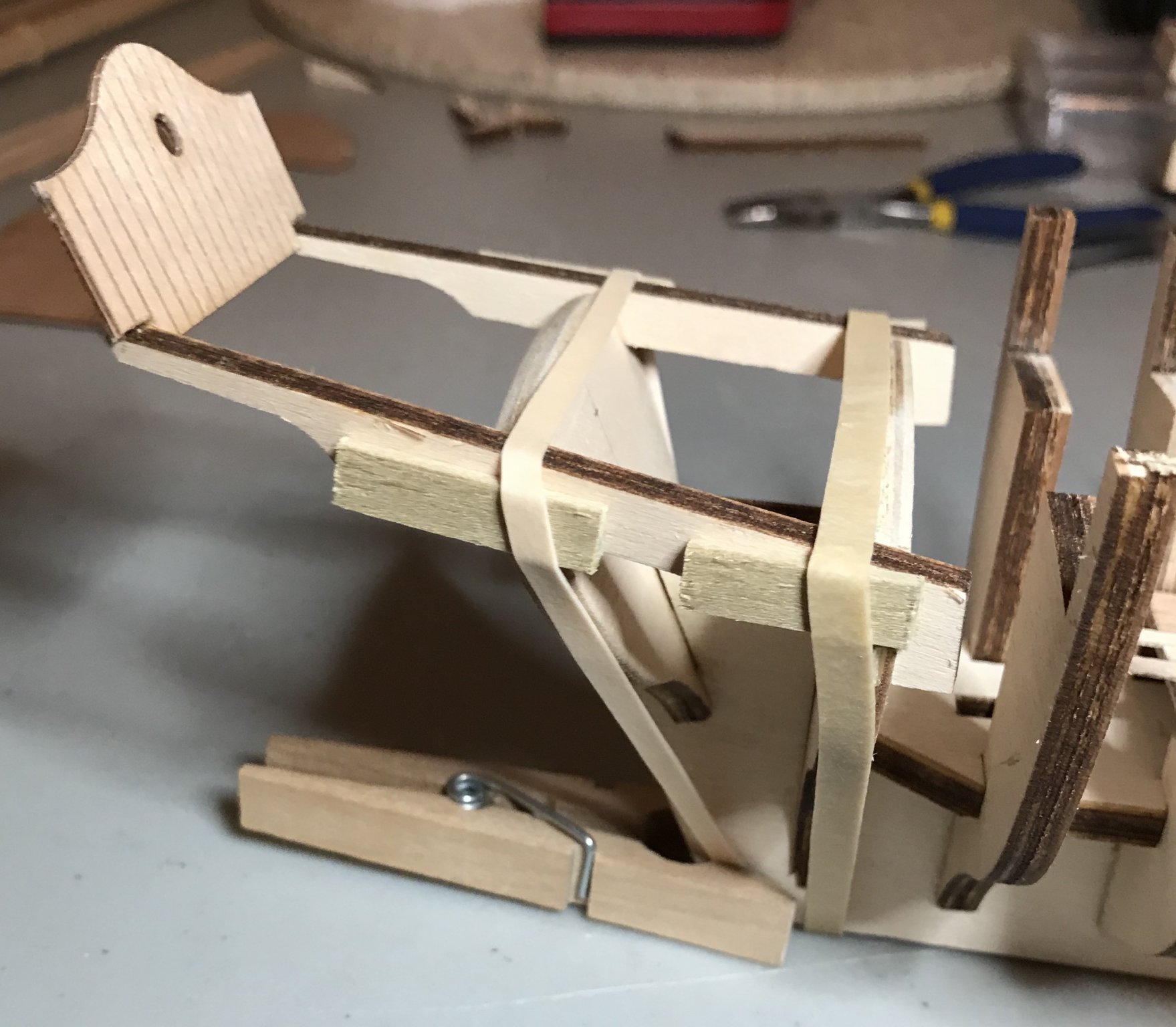
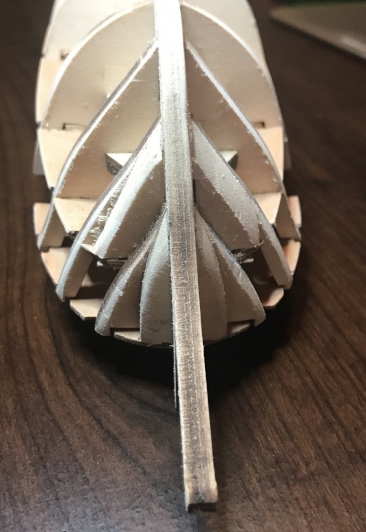
I've made a little more progress this weekend. After much sanding and adjusting, I finally got out the glue bottle. The bulwarks are now firmly attached, as is the main deck. The main deck needed eight shims of various thickness (.5–2mm) in order to be securely attached to the bulwarks. The next two challenges were dealing with the longerons/stern piece and working out a sequence for proceeding. First, the longerons and stern piece. Even in the diagrams, the longerons don't look like they are attached to flat surfaces—but sanding down those surfaces that far would cause alignment problems with the aftdeck. So, I've done it more or less like the diagrams. It was really tricky to figure out the alignment, though. The pieces are basically L-shaped, with the 90º angle hooking over bulwark #11. They then extend backward over bulwark #12 and the stern piece attaches to the end. (A note for others who might build this kit: it's only apparent in one of the diagrams, but the bottom corners of the stern piece need to be cut off to fit the ends of the longerons. This also helps immensely with alignment.) I ended up using a couple rubber bands to keep them in place while the glue dries. The short planks will ultimately be added to extend the bulwarks vertically, to be a base for side planking. Until the longerons are set, though, they're just stuck in there to help with alignment. Alignment of the longerons was really tricky, since they really like to shift around laterally, and every photo I took made that alignment look worse than it actually is...I never found the right camera angle, I guess. Here's a shot that doesn't look too bad. Notice how the sternpiece is really floating out there? It's lined up with the angle at which the ends of the longerons are cut. Until the side planking goes in, there isn't much support for it, but without it being there, there's no way to line up the longerons! Second, the sequence for proceeding. At this point, the sequence issue also came up in the Italian build logs that I read. The assembly instructions call for bulwarks/longerons, decks, hull/side planking, then deck planking. However, the fore- and aft-decks cover up significant portions of the main deck, making the deck planking problematic. So, I'm going to do the middle 15 deck planks and all of the planks between bulwarks #8 and 9, then I'll attach the other two decks and get started on the hull planking. To wrap up for tonight, a couple shots of where things stand (with an unfortunate overhead camera angle that makes it look more crooked than it actually is!). The ship is already pretty long compared to my previous kits—17 inches/43cm—but is really starting to take on the xebec shape.


- 79 replies
-
- 2
-
-
- sergal
- sciabecco francese
- (and 1 more)
-
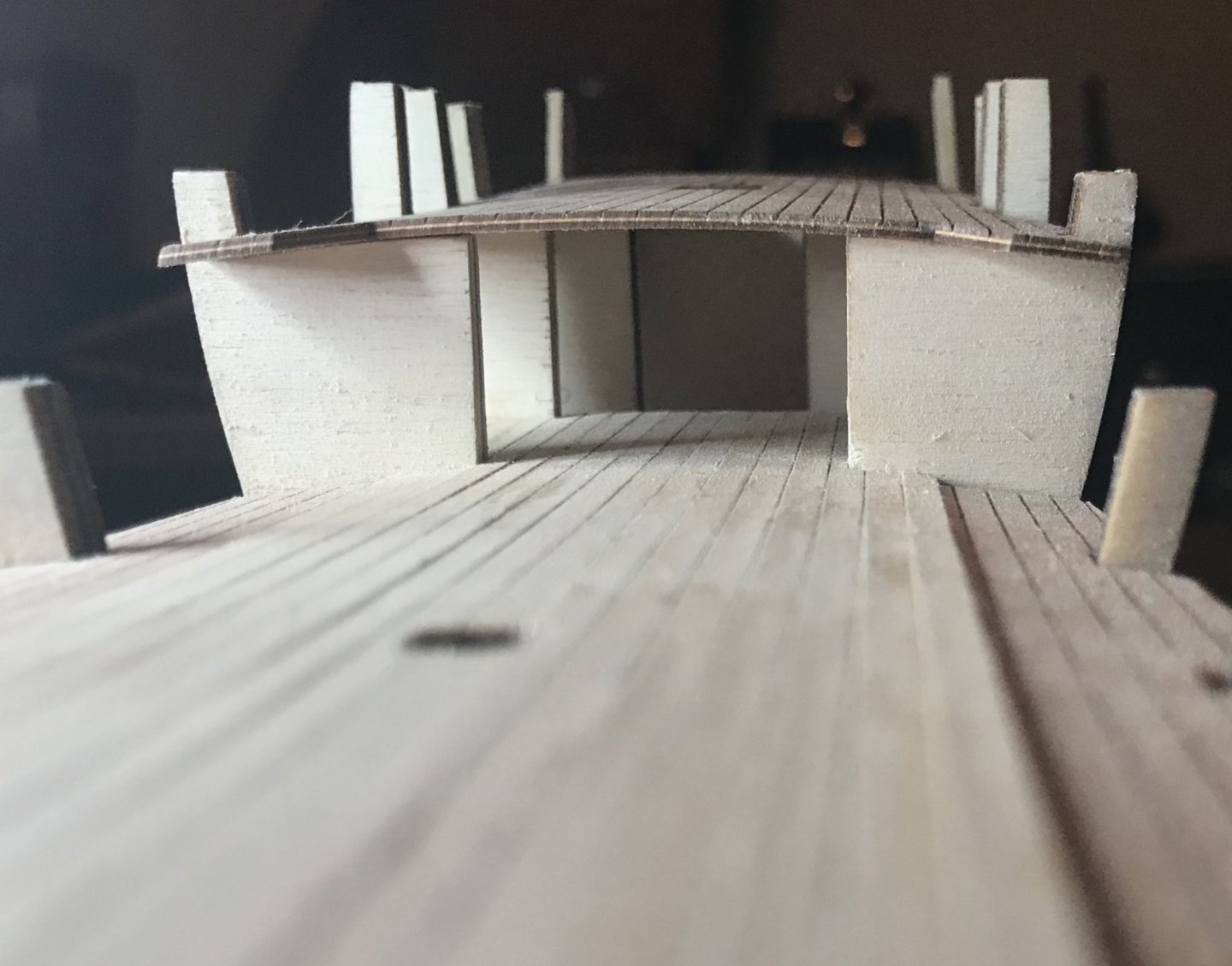
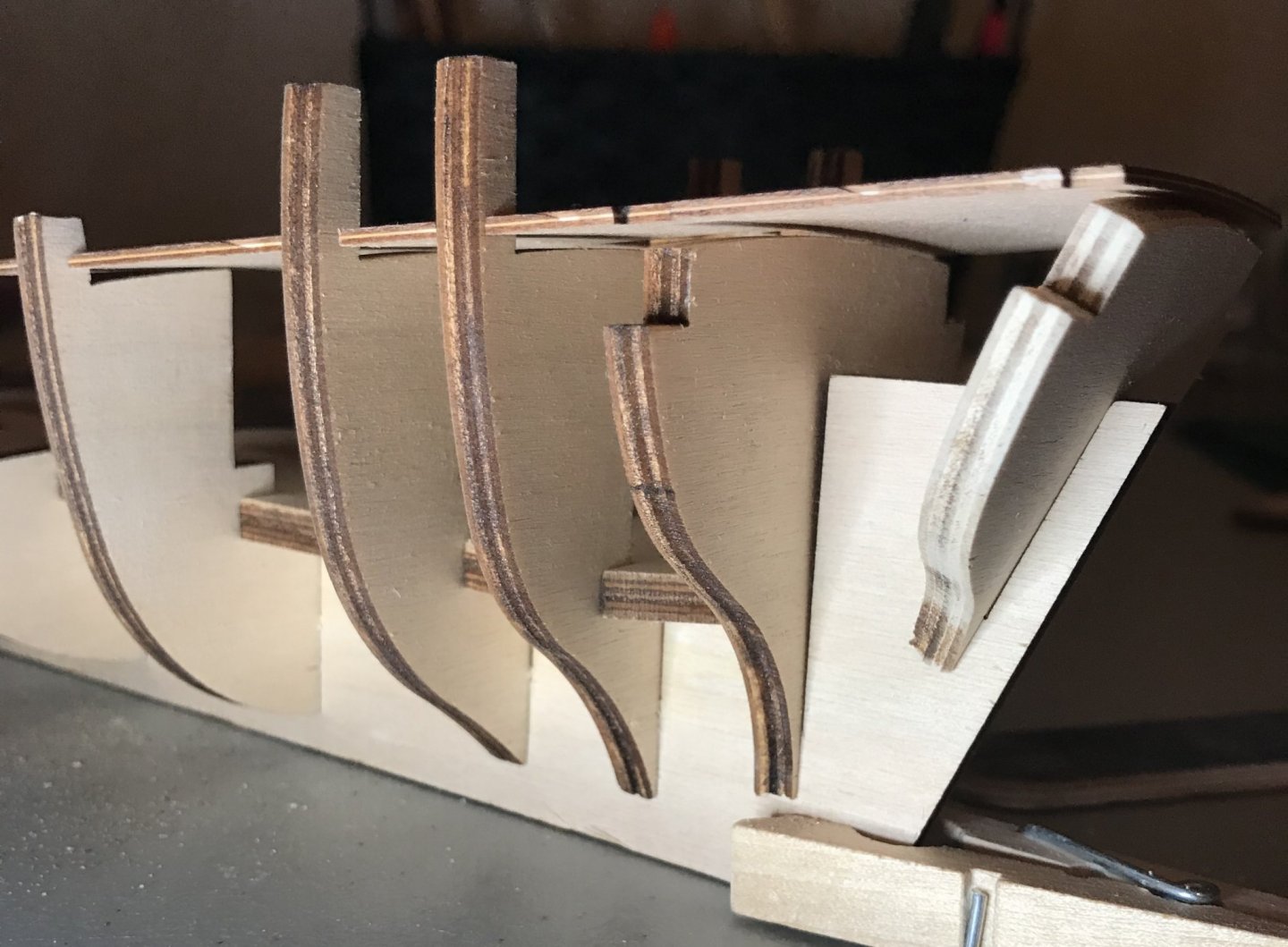
Thanks for the compliment, Bob! Last night, I was admiring your work on the Pen Duick, which looks fantastic! I thought I was all set to glue the bulwarks into place, when I happened to look at the aftdeck from a different angle. I have some serious sanding left to do back there! The photo is looking at the aftdeck and bulwarks #8–12. Right now, there's solid contact only on bulwarks #9 and #12 and some contact on #8. But the deck is floating a couple millimeters above bulwarks #10 and 11! I think that everything is seated deeply enough into the slots on the keel, so I just need to shape the tops.
- 79 replies
-
- 2
-
-
- sergal
- sciabecco francese
- (and 1 more)
-
Hi Bob and Adam, thanks for the interest! My skills are getting better, but I still feel like a beginner in a lot of ways. Thanks in advance for any tips you might find helpful to share! The keel and false deck straightened up somewhat since last night. They're at least straight enough that they line up well when everything's assembled. The camera angle in the overhead shot added a curve that isn't really there. I spent some time tonight dry fitting the decks. I was surprised that they came pre-lined...not sure if that's common? The instructions indicate that the deck will be planked, so I guess they're just there for reference. All three decks had some significant issues with inaccurate cuts. On the main deck, 8 of the 14 slots were not cut deeply enough in toward the middle and 2 of them were cut too deeply; the lines came in handy here, since they made it much easier to measure the cuts that I needed to make. The fore- and aftdecks, on the other hand, had slots that were either too far forward or too far backward. In the overhead picture, you'll note that the original slots for bulwark #3 were too far forward; in the aftdeck the slots for bulwark #8 were too far back and those for #9 too far forward. The slots for bulwarks #9 and 10 were cut a little too deeply, too, so there's a little bit of play right now. Other than that, everything's fitting snuggly, but not tightly.

- 79 replies
-
- 2
-
-
- sergal
- sciabecco francese
- (and 1 more)
-
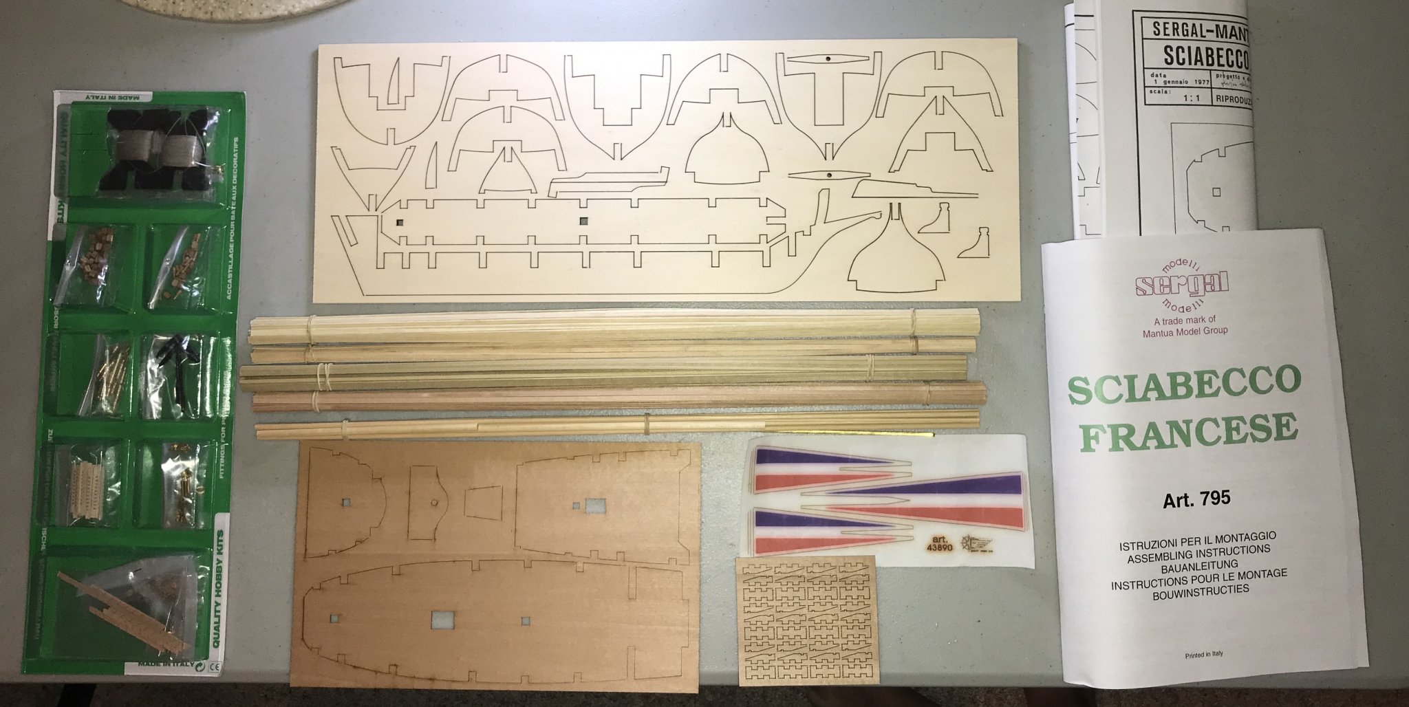
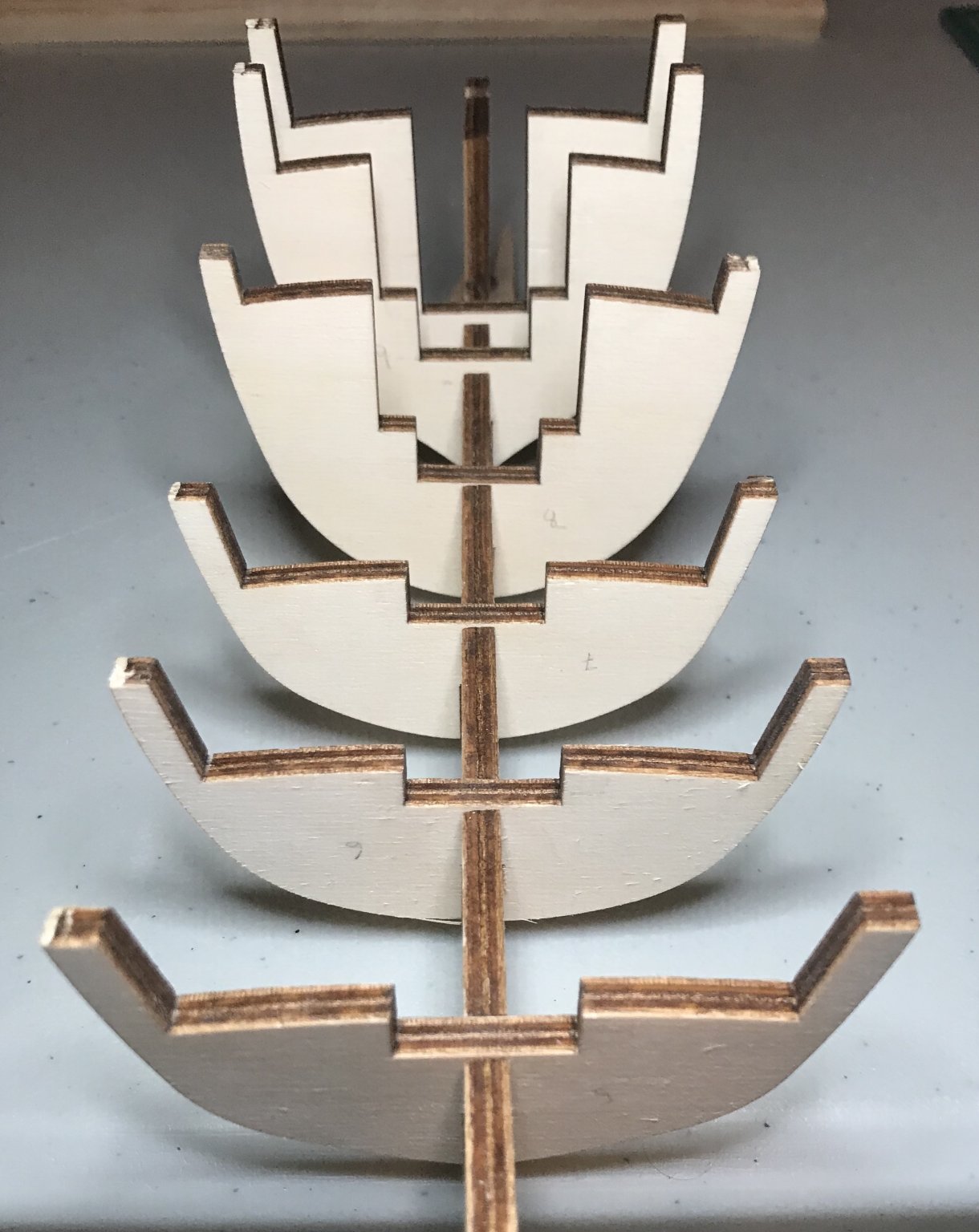
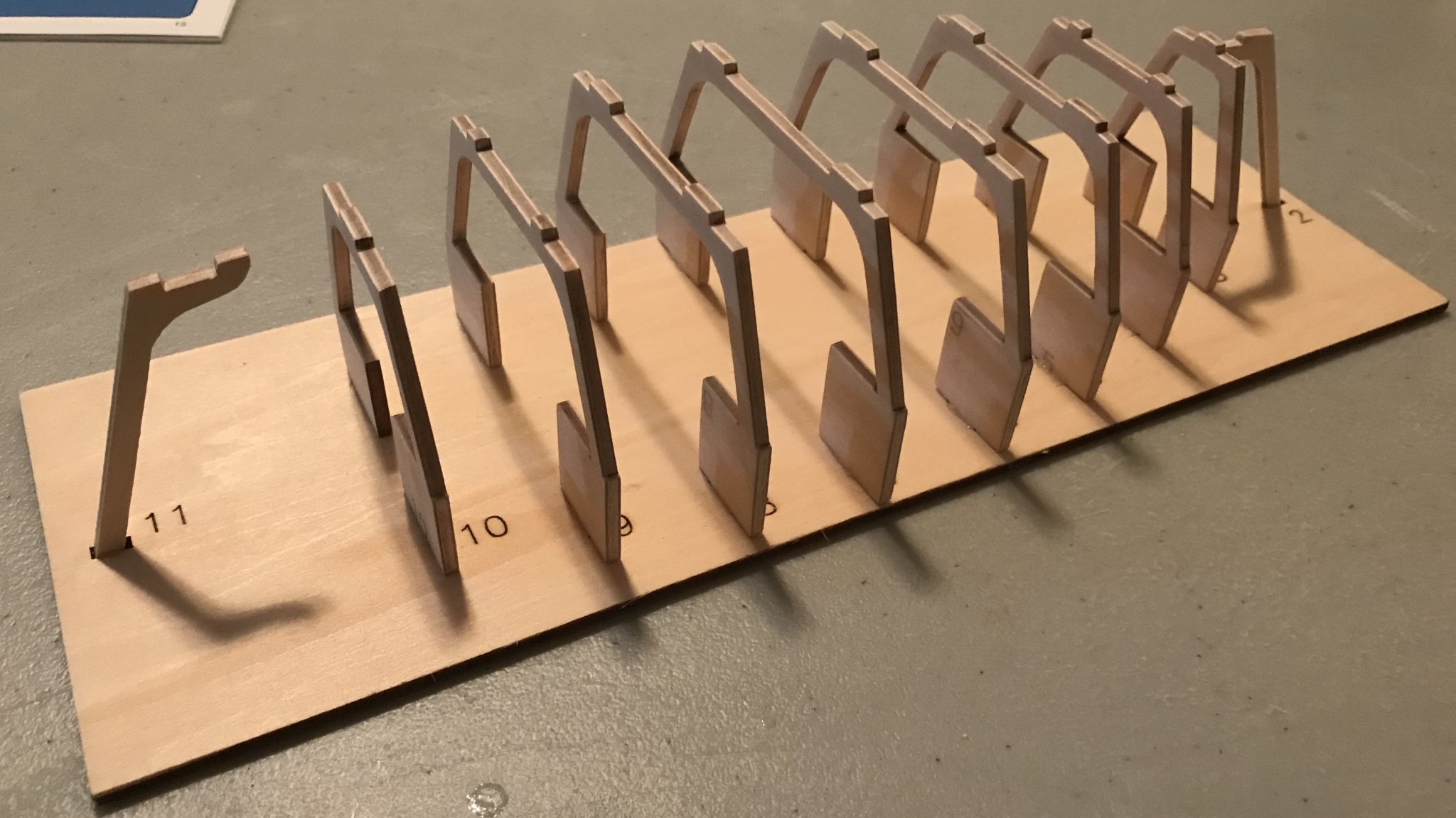
Finally saved up enough to order my fourth kit! After three reasonably successful builds of beginner kits by Artesania Latina, I'm stepping up to an advanced beginner kit from Sergal (a brand made by Mantua Models). The kit seems to be sold under both its Italian and English titles, respectively, Sciabecco francese and French Xebec. While xebecs were used by other countries' navies earlier, the French didn't adopt them until relatively late in the reign of Louis XV, in the 1750s and 1760s. The French navy continued to use them through the Napoleonic wars, though they were mostly phased out at that point. (Apparently some worked coast guard duty into the 1840s.) Here's the traditional unboxing photo. Four bundles of 500mm planks and dowels, three sheets of laser-cut parts, a sheet of pennants, lots of hardware, the assembly instructions booklet, and some rather generously sized schematics. Although the assembly instructions are pretty limited, they also include a section on planking the hull that is very detailed and well illustrated. I don't have much perspective, but the wood doesn't seem to be of the same quality as the Artesania Latina kits that I did. That might be just the perception of an amateur talking, or maybe it's just that the wood was less well sanded at the factory. The 5mm plywood is definitely sturdy though! The biggest concern for me so far is that the keel, false deck, and decks have curves to them. Right now, I have the keel and false deck resting under damp paper towels and some heavy weights. Hopefully they'll be straighter tomorrow. Today I began dry fitting the keel and bulwarks. I've learned a lot from my prior kits and so am doing better this time. The bulwarks fit well to the keel, straight out of the box. I sanded the laser char off one of them, but then it fit so loosely that it rocked back and forth in its slot on the keel. Now I'm only sanding off the char as needed to improve how the false deck and decks fit. Although the bulwarks fit well, the slots weren't deep enough. The photo shows bulwarks #5–10. You'll note that #9 and 10 (the two furthest away) are sticking up above the keel by about 2 or 3mm, which is about how high they all sat. When I took the photo, I noticed that #6 and 7 were still up a bit too high, too, so I gave them a bit more love. At this point, the bulwarks that support the false deck (#3–10) are fitted. The false deck slides into its space well, except that its slight curve prevents it from resting flat. Next step is to dry fit the main deck (which needs some filing in order to fit onto the bulwarks) and then to work on the foredeck and the bulwarks (#1–3) that support it.


- 79 replies
-
- 4
-
-
- sergal
- sciabecco francese
- (and 1 more)
-
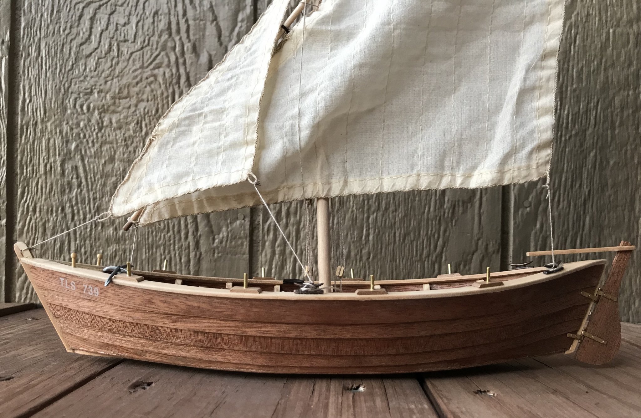
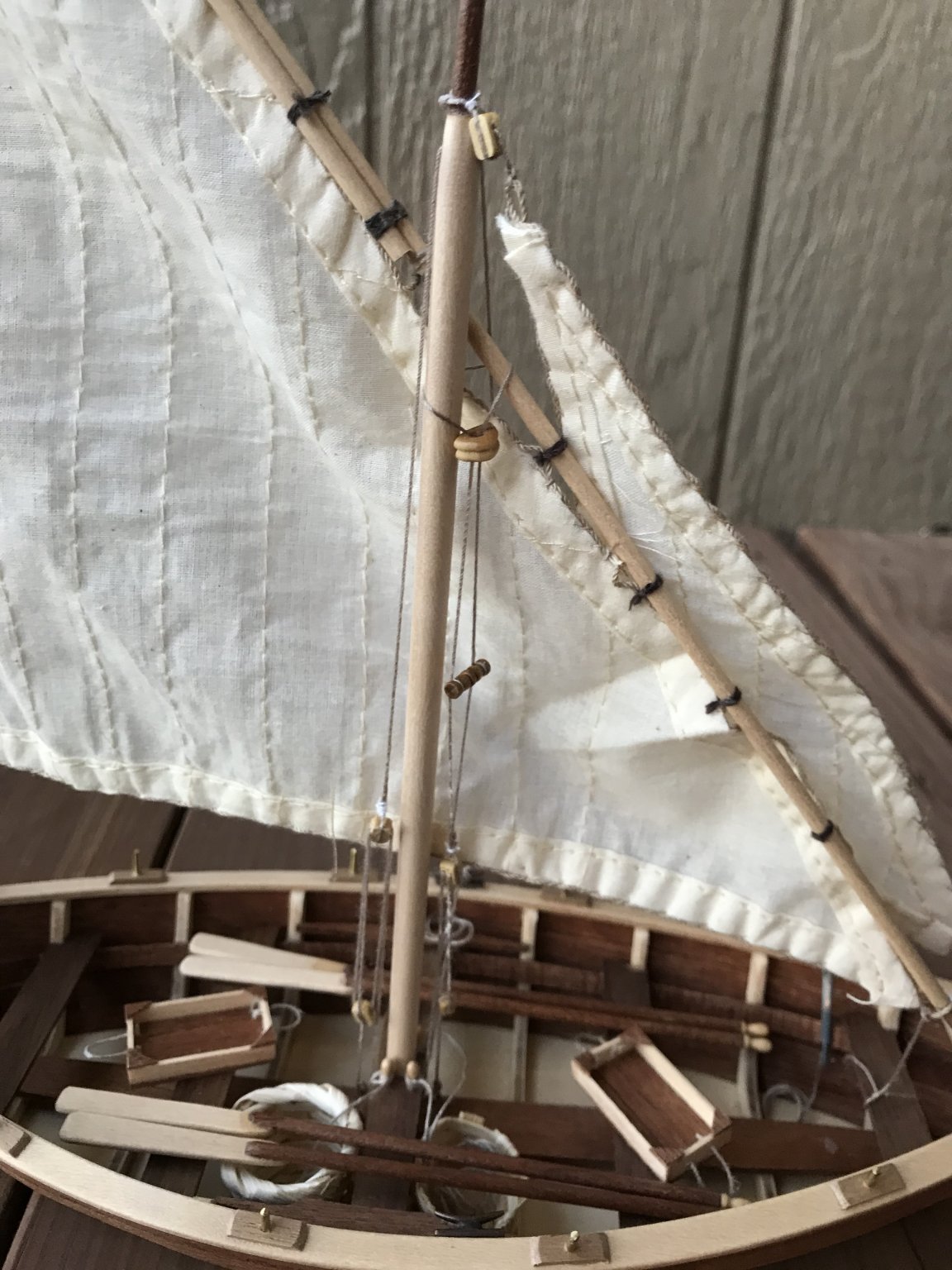
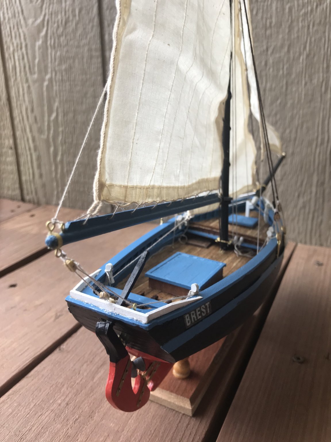
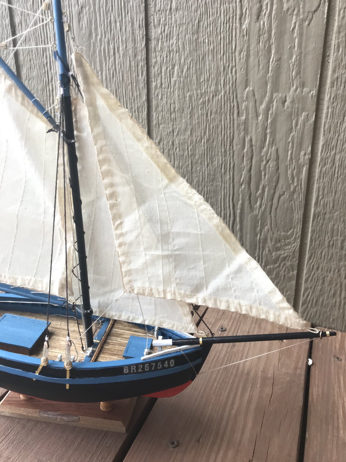
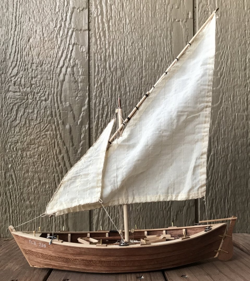
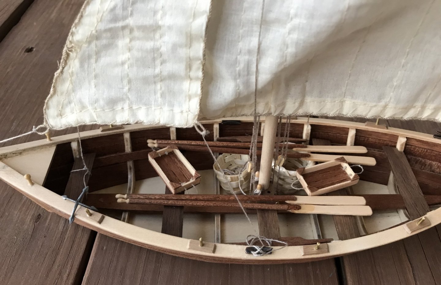
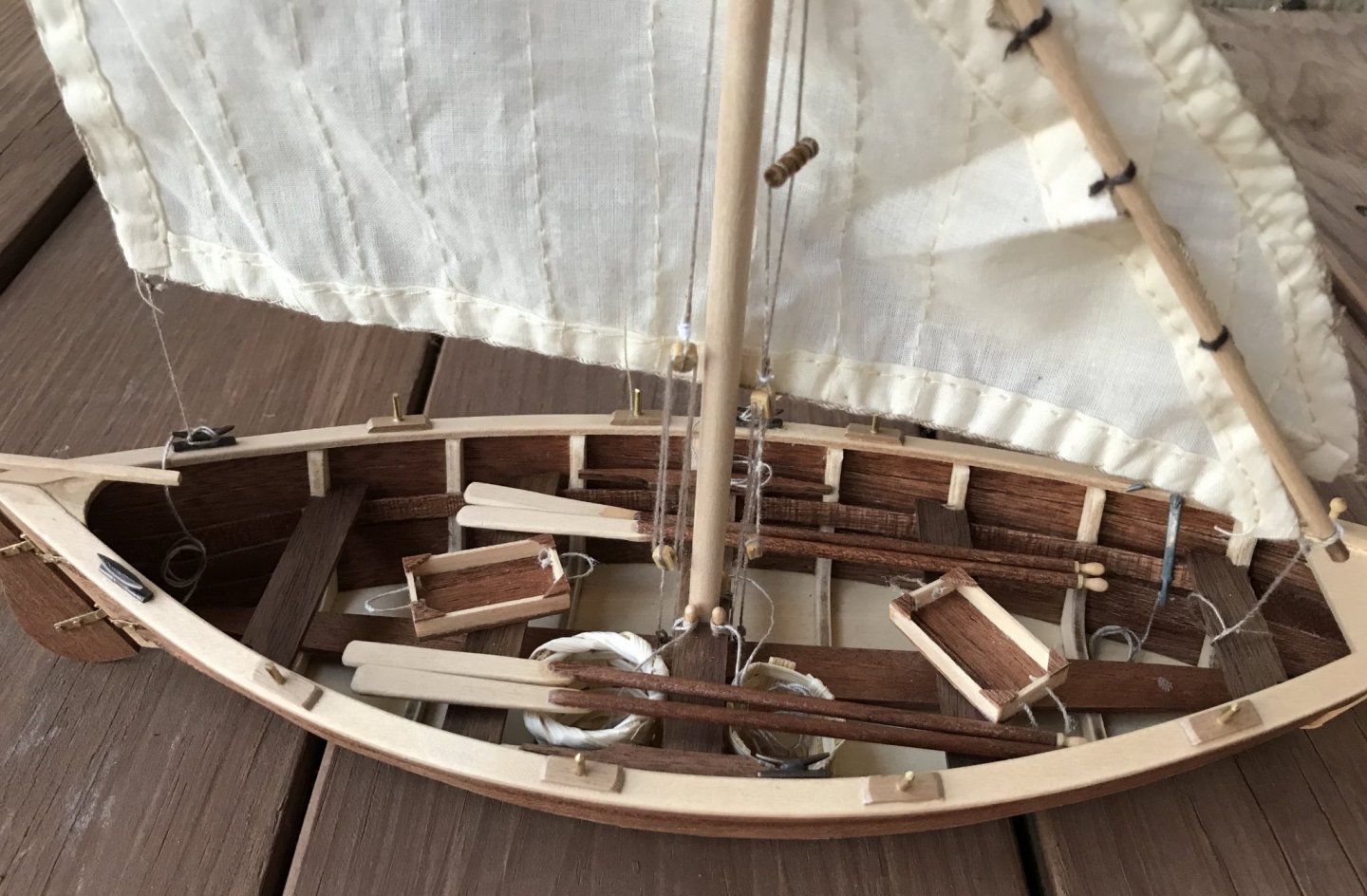
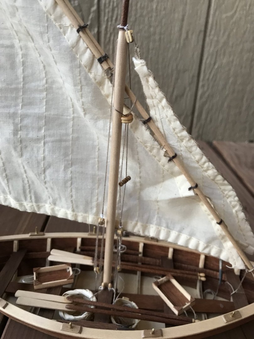
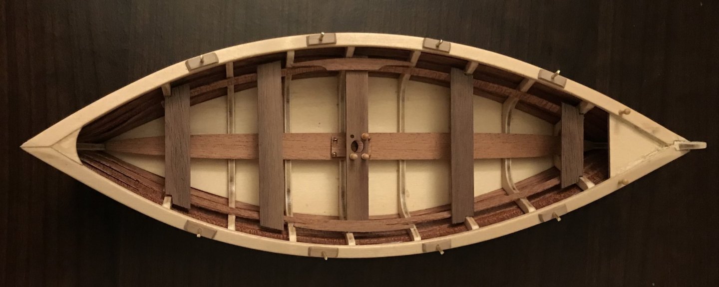
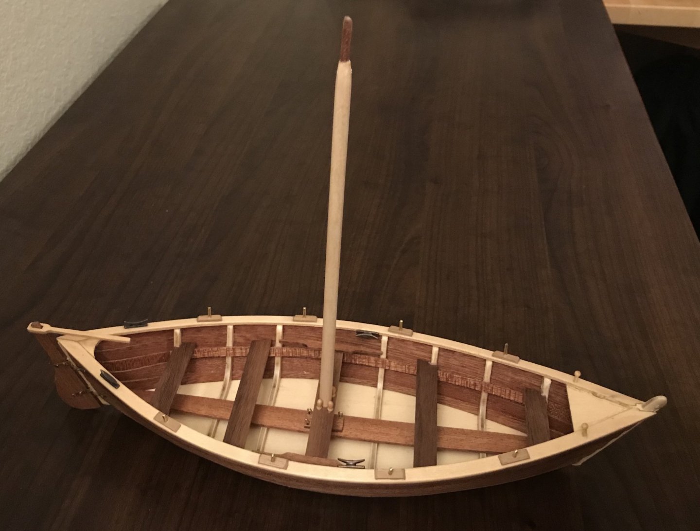
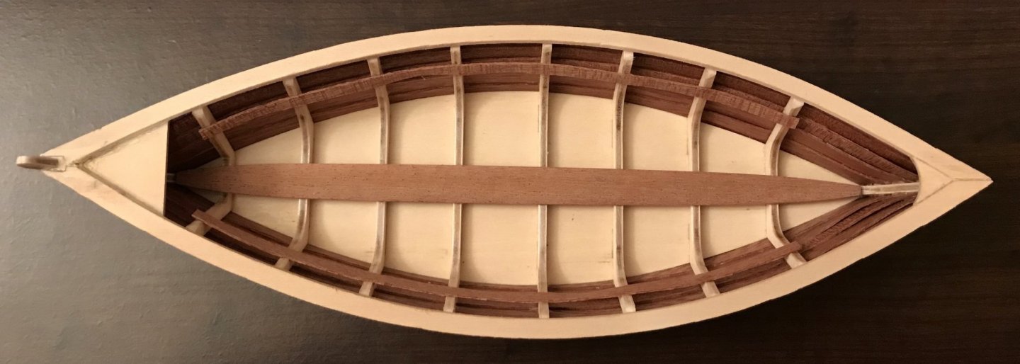
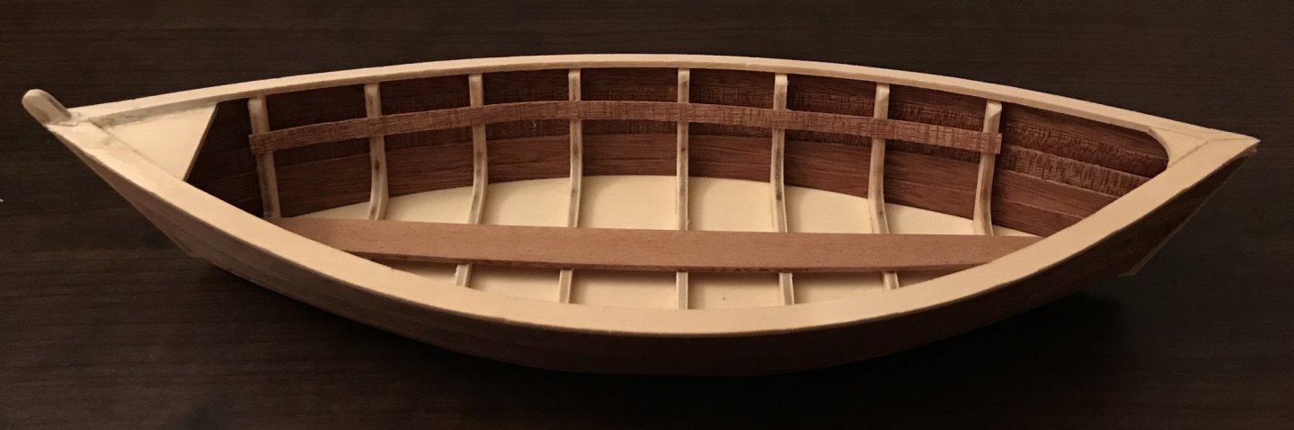
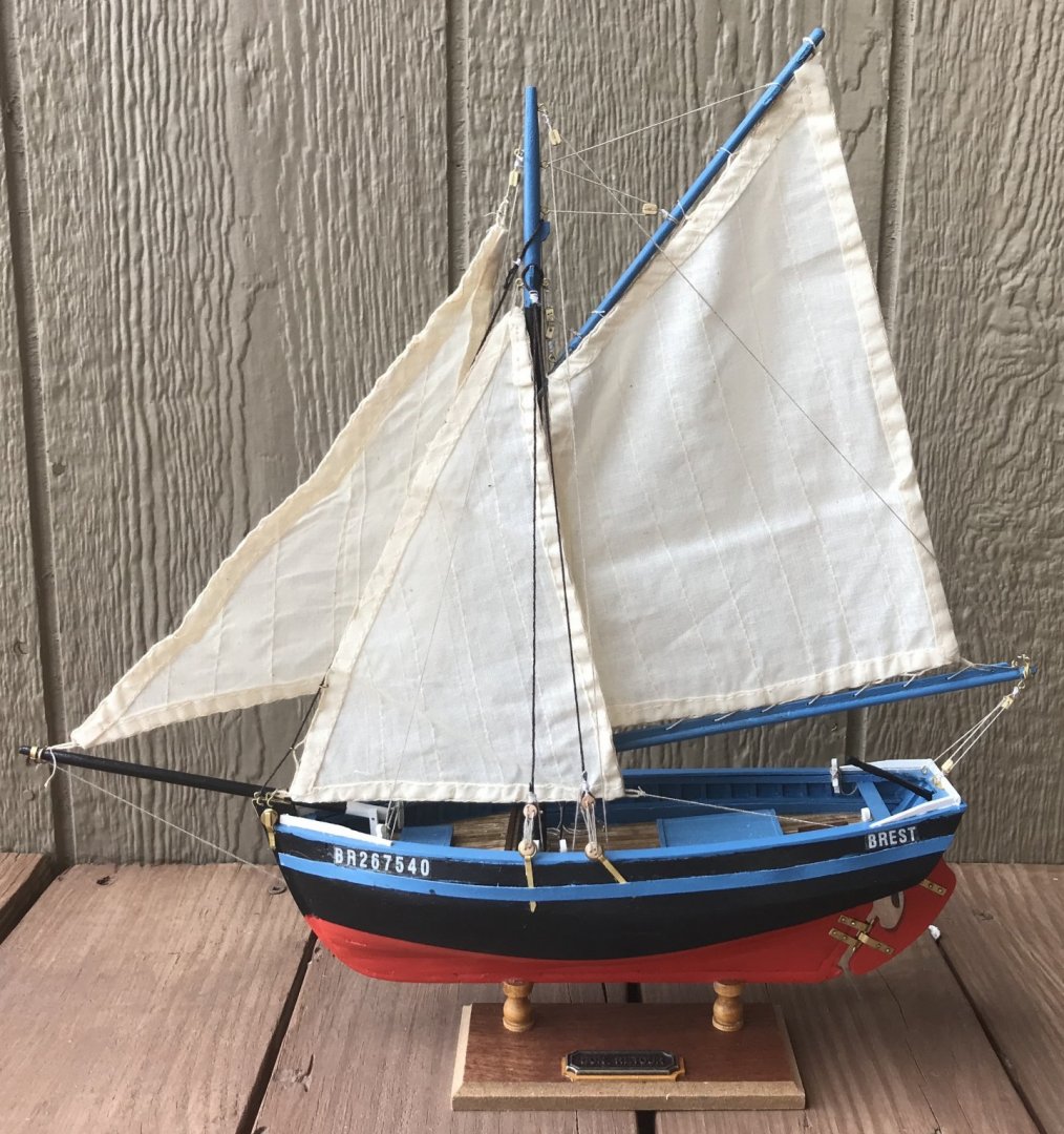
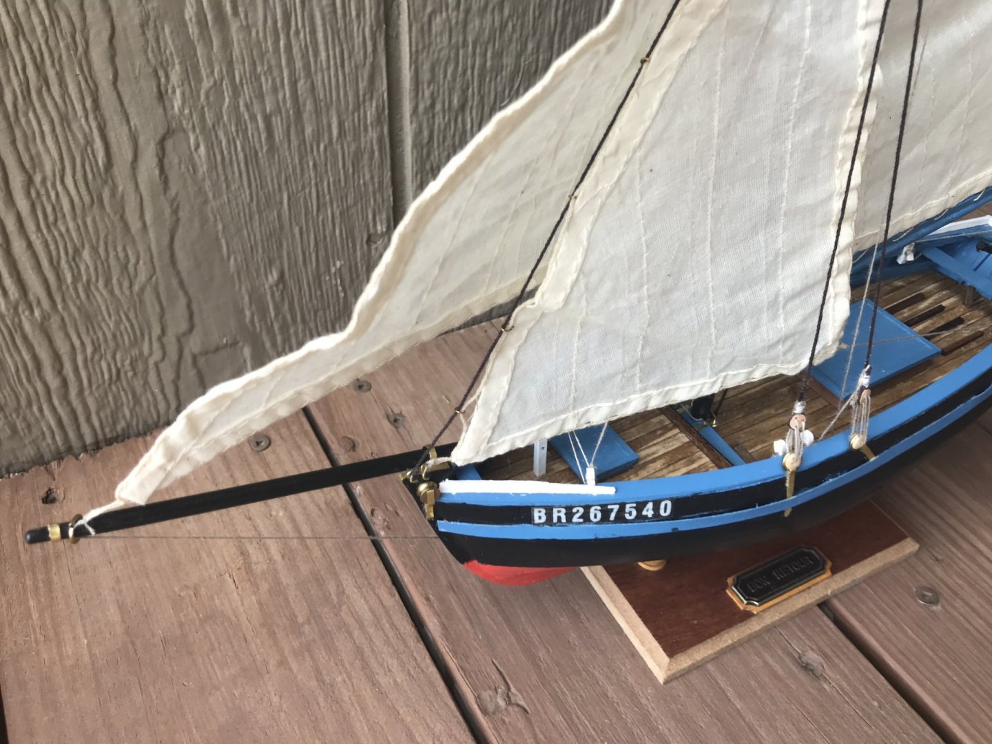
While building the boat itself and all the extra equipment, I found the instructions for this kit wonderfully clear and helpful, though the indicated measurements didn't always pan out. But the rigging? Although the instructions were detailed and clear, they were not accurate. #49 is labeled on two different ropes, both of which are involved in raising the lateen sail (one runs from the yard to the double block on the left side of the map in the photo below; the other from the deck, through those blocks, to a belaying pin on the middle bench). The instructions were not easily applied to the boat in my hands, either, so I ended up relying on a combination of the photos in the instructions, videos of people rigging lateen sails, and my own intuition. In the end, I think I got it mostly right. I struggled a bit with the rope on right side of the mast in the photo. The triangular block is intended to hold the yard tight to the mast. I never did manage to get that as tight as I thought it should have been. I was also not satisfied with the reefing stays, which kept flying up above the yard; I ended up just cutting those off. I also ended up moving one of the cleats from the rounded side of the gunwale cover onto the top of the cover; before I gave up and moved it, I think it popped off five times while I was belaying a rope to it. However, the boat is finished! Here are the obligatory celebration shots. First, two profile shots from port: one featuring the entirety of the lateen sail and the other focusing more on the hull. Next, two shots looking down into the boat: first from port and then from starboard.

- 12 replies
-
- 6
-
-
- la provençale
- artesania latina
- (and 1 more)
-
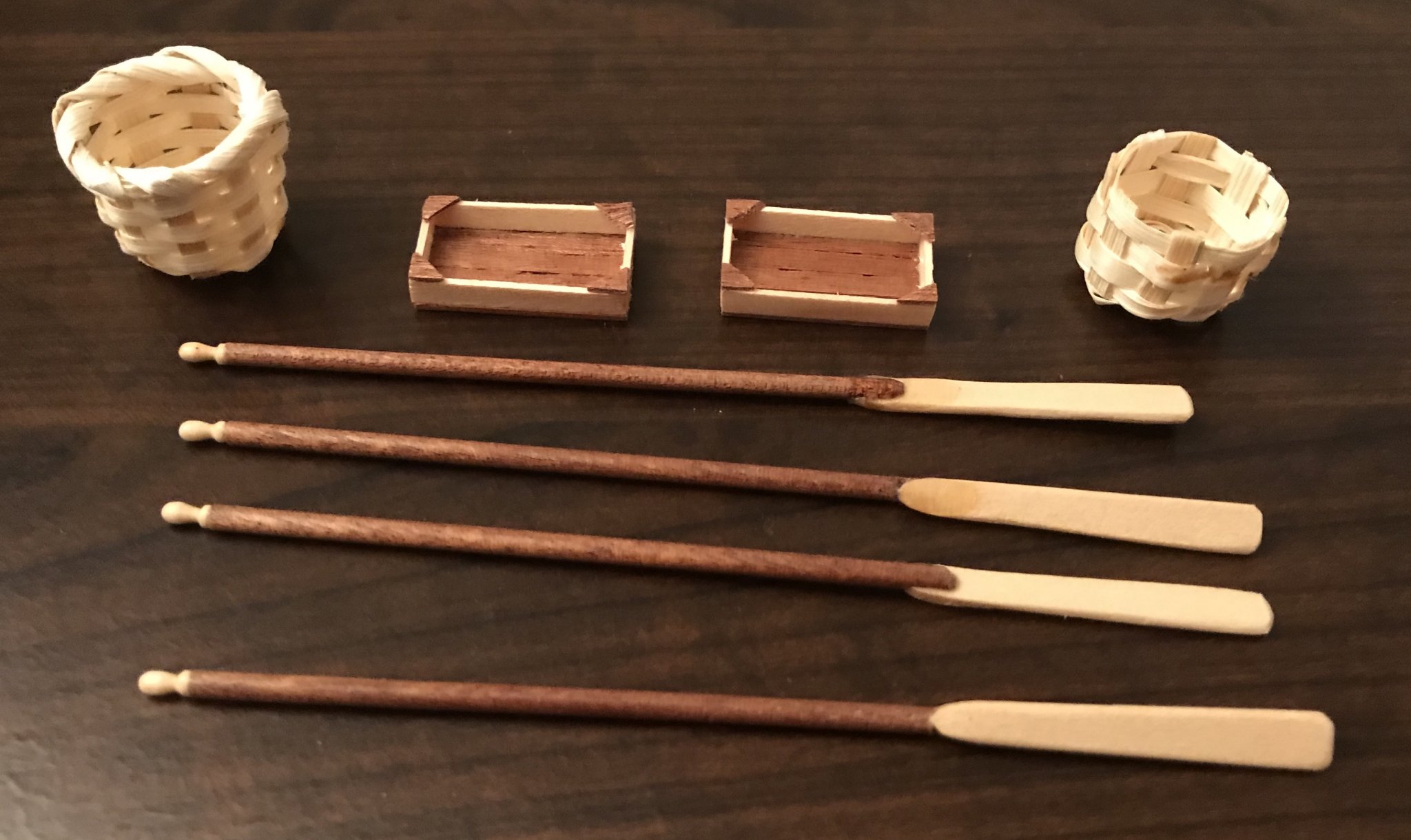
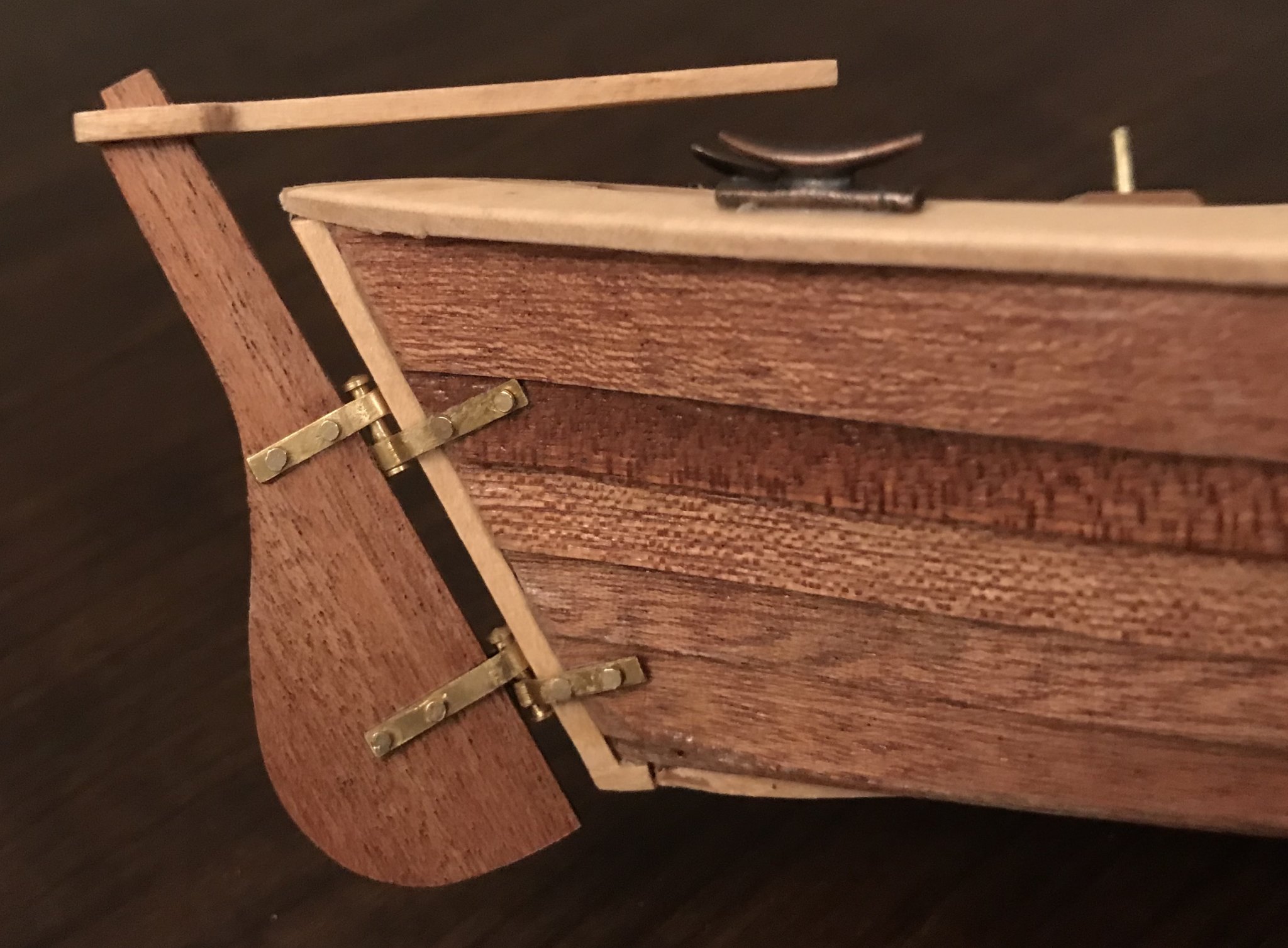
Despite some challenges for a novice like me, this boat has come together very quickly! Today I finished building the boat itself; all that remains is to do the rigging and to put the handles on the "fish boxes" (we called them lugs on my grandpa's tomato farm, but "fish boxes" is the description in the instructions). To finish off step 9, I added the strengtheners to the middle bench. This took a little more work than expected, since I had to sand them down to be flush with both the frame ribs and the bench; nothing bad, just a lot of going back and forth between sanding and checking the fit. Next, I popped the three belaying pins into their respective hole on the middle bench. Then, I constructed the oar locks. These were made by cutting 13mm pieces of a walnut strake, rounding the top ends, drilling a hole, and inserting short pieces of 1.5mm brass wire. Photos are an overhead shot of the whole boat at this stage and a detail of the middle, showing the different types of pieces added in this step. Then it was on to step 10! This began with applynig finish to all of the parts added in the previous step. Once that was done, I glued the four cleats into place. Since these were metal and the finish was on, I discovered that PVA glue was useless here and, for the first time, successfully made use of CA glue. The two attached to the sides of the gunwale cover were particularly tricky, since the cover was rounded in an earlier step and there was less surface area to attach them to. Then I turned to the rudder. On my previous kit, I got the job done with the rudder, but can't say did it well. This time, I sought out more advice on fitting the rudder hinges; I couldn't find quite what I needed on MSW, but found some very practical advice here. The measurements from the instructions made no sense when I translated them onto the wood in front of me, so instead I just went with what looked right and fit best. Still not perfect, but I did the job more neatly and much more efficiently this time! Finally, the last part of step 10—and the last part of the boat itself—was the mast. Without a lathe, I'm still working on how to make these conical, so the tapering at the top feels a bit dramatic to me. While the main shaft is from a basswood dowel, the top is cut from a smaller walnut dowel. I had a terrible time getting them to stay aligned when I was glueing them, so ended up wiping it all off and starting over. I drilled 1mm holes in each of them, a few millimeters deep (I couldn't go more then 2mm into the main shaft because I also needed to drill a hole through the main shaft for the rigging). Then I glued a pin in to strengthen the joint. Once that was installed, the boat was finished except for the rigging. While waiting for glue and coats of finish to dry, I also finished up the extraneous bits of the kit: 4 oars and 2 fish boxes (which still need rope handles added). They're shown here with the two pre-made baskets that come in the kit. Next steps: Since I've already assembled the yard, I just need to attach the lateen sail to the yard and run the rigging for both sails.


- 12 replies
-
- 1
-
-
- la provençale
- artesania latina
- (and 1 more)
-
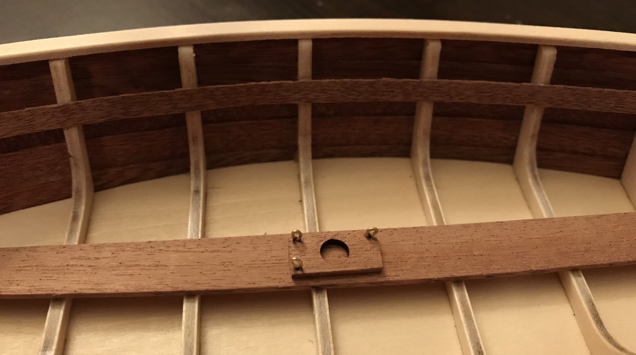
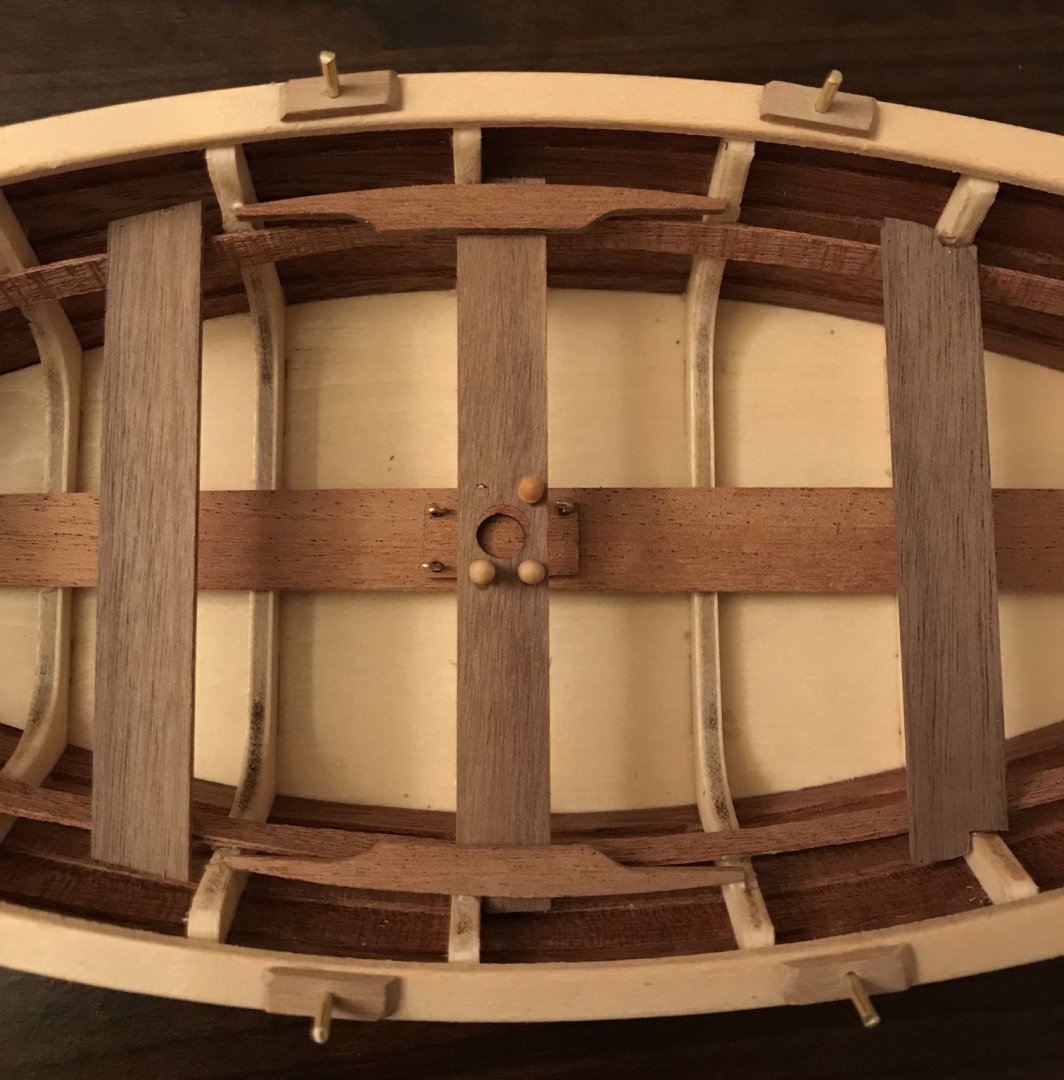
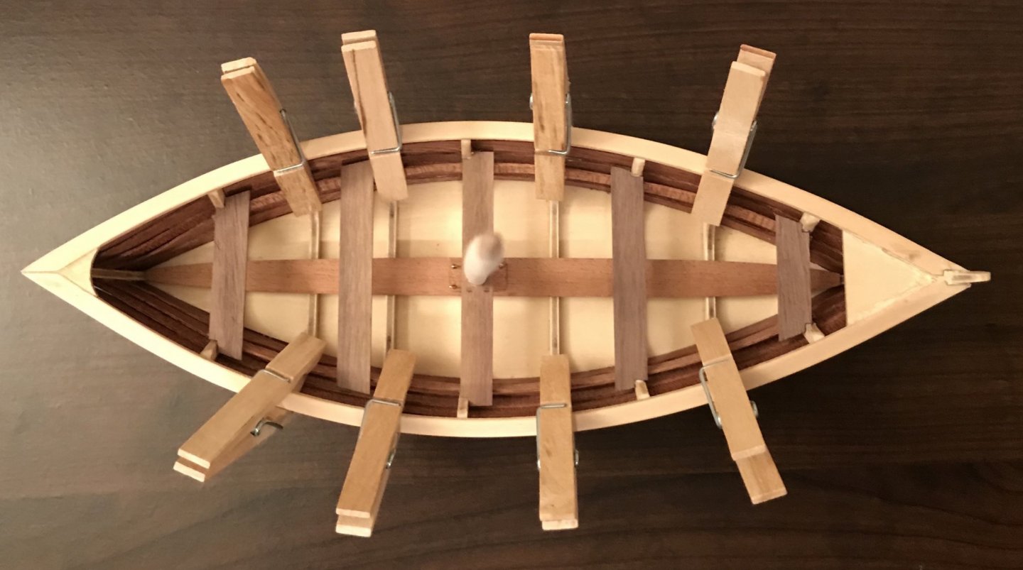
Steps 7 and 8 proved more interesting and problematic than they should have. Picking up where I left off on step 7, I first fit and shaped the gunwale covers and bilge keelson, then glued them into place. Because of the boat's vertical curve, these were trickier to shape than I would have hoped (though could probably be easier if your tool set is more plentiful than mine). I used 17 clothespins per gunwale cover; for the bilge keelson, I placed three 1oz bottles of paint on it, then set a wrench on them (the heaviest tool I had that fit the length; the rubber grip on the handles conveniently got thicker right where I needed it to in order to get the necessary curve). When I got to glueing the gunwale covers, I ran into my first problem: while clipping one of them into place, I managed to snap it into two pieces. I filled the break with glue and sanded a bit to get some sawdust mixed in. The next morning, once everything was set, the break was almost invisible (almost!). I then finished off step 7 by adding two battens to the inner frame; these are the bases for the benches. The measurements from the top of the battens to the top of the gunwale covers are clearly indicated, seemingly making placement very easy. (Yup, foreshadowing. I'll get back to that.) I then dove into step 8, adding the front and rear stanchions to the gunwale covers. I also rounded the edges of the gunwale covers and stanchions . I needed a bit of wood filler around the stempost and front stanchion...these photos were taken while that was drying, so things look a bit raggedy there. The last part of step 8 is to attach the mast hole cover to the bilge keelson. This needs to line up with a hole above it, in the middle bench. So, I slid the mast through the bench and the cover. After applying glue to the cover, I aligned the bench in its spot and slid the cover down. Once it was in place and the glue was drying, I needed to insert three eyebolts into the smaller holes on the cover. Here was problem #2—the kit didn't include any eyebolts! I found some tips here on MSW and so made my own out of brass wire (actually, out of the pin shafts that had been scrapped when I made the rivets for the Bon Retour—glad I hung onto those!). Using pliers, I wrapped the wire around a 1mm drill bit to make the eye. I can't say that I made perfectly shaped eyebolts, but they are at least functional. While fitting the mast cover, I had gotten my first hint of problem #3. While the glue was drying on the eyebolts, I looked ahead at step 9, which begins with the installation of five benches. They are all preformed, so I sanded off the laser char and then set them on their bases, just to see how they would look. That's when I discovered that the battens were several millimeters too high, despite following the measurements in the instructions! Working as carefully as I could, I used my Exacto knife to remove the battens. After scraping and sanding the dried glue off, I set about reinstalling them. This time, I began with the benches. Working one bench at a time, I taped a mini spirit level to it (see the photo below), found the correct height for the four benches that attached to the ribs of the frame, and then made a mark underneath, where the batten needed to be at that point. I dabbed glue onto my marks and the middle bench, then aligned those (using the mast again to ensure that it would fit later on). I worked outward from the middle bench, attaching the four benches and battens to the ribs. Then, I dabbed used a toothpick to apply glue between the battens and the remaining ribs, holding them in place with clothespins once everything was adjusted. Finally, I added the fifth bench, which is positioned between ribs and so is only attached to the battens. Next steps: finishing step 9 by adding strenghteners to the middle bench, belaying pins, and oar locks, then applying finish to everything added in this update.


- 12 replies
-
- 2
-
-
- la provençale
- artesania latina
- (and 1 more)
-
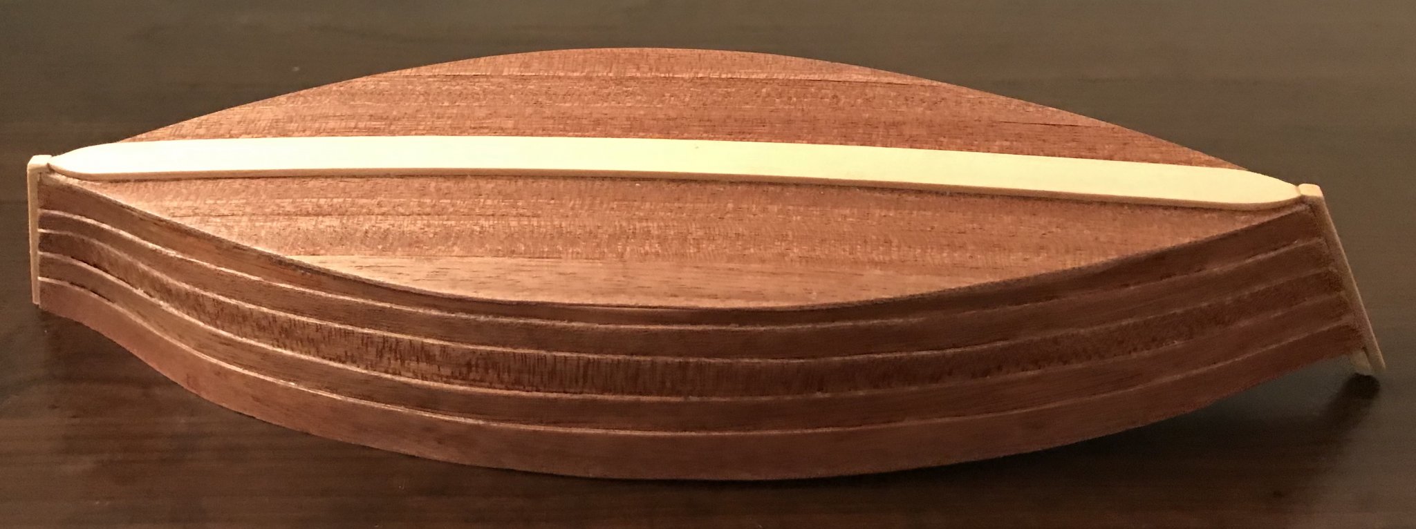
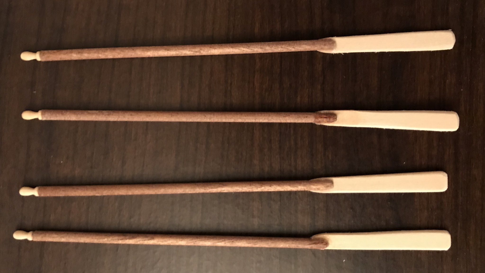
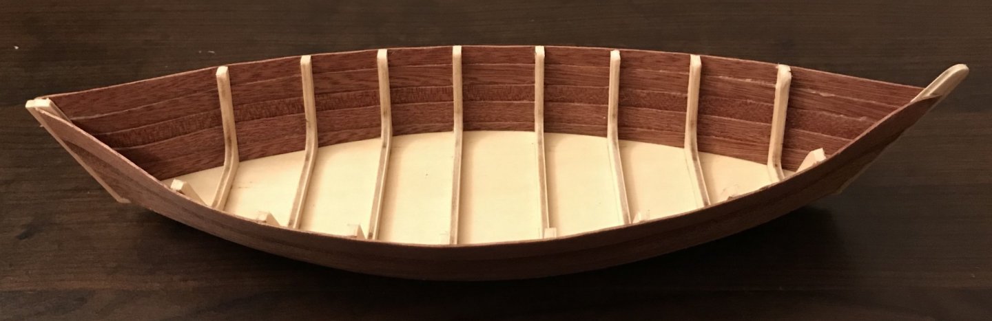
After removing the boat from the frame base at the end of step 5, step 6 focused on sanding and adding the stiffeners to the stempost and sternpost. The stempost is sanded to a rounded top, and the frame ribs are also rounded (though they'll soon be hidden by the gunwales). As I mentioned before the keel is a few millimeters short...I did an okay job with the bits I added to lengthen it all the way to the stempost and sternpost. Wish those looked a bit better, but they were a real pain to get them shaped as closely as I did and to glue them on. The first part of step 7 involves applying finish to the hull, inside and out. So, in the photos, there's a little bit of a sheen from that. The finish really brought out the gorgeous color of the sapelli! While waiting for things to dry, I've looked ahead to see if there were any bits that I could prepare ahead of time. Because this kit doesn't make it easy to account for your resources, I'm waiting on most of those things. However, I did get the oars assembled. (They look better in person...one of them is tipped toward one side, making it look worse in the photo than in real life!). The oars consist of sapelli dowels cut to size for the oar shafts, precut pieces for the blades, and belaying pins with the bottoms cut off for the grip. The sapelli dowels are a great example of why it's essential to look ahead in this kit. The four dowels here—each 90mm long—are cut from the two dowels that come in the kit, each of which is 200mm long. If you follow the instructions strictly in order, then before you come to the oars, you come to the mast top and the tips of the yard, which require one 15mm and two 20mm pieces of the same dowels. So, there will only be 5mm of scrap, and if you don't cut the mast top and the yard tips from different dowels, then you won't have the lengths necessary for the oars. Unfortunately, the parts list in the instruction book does not list the lengths of the pieces that need to be cut, making it necessary to carefully study the instructions in order to use your resources wisely. Next steps: adding the gunwales and the bilge keelson.

- 12 replies
-
- 2
-
-
- la provençale
- artesania latina
- (and 1 more)
-
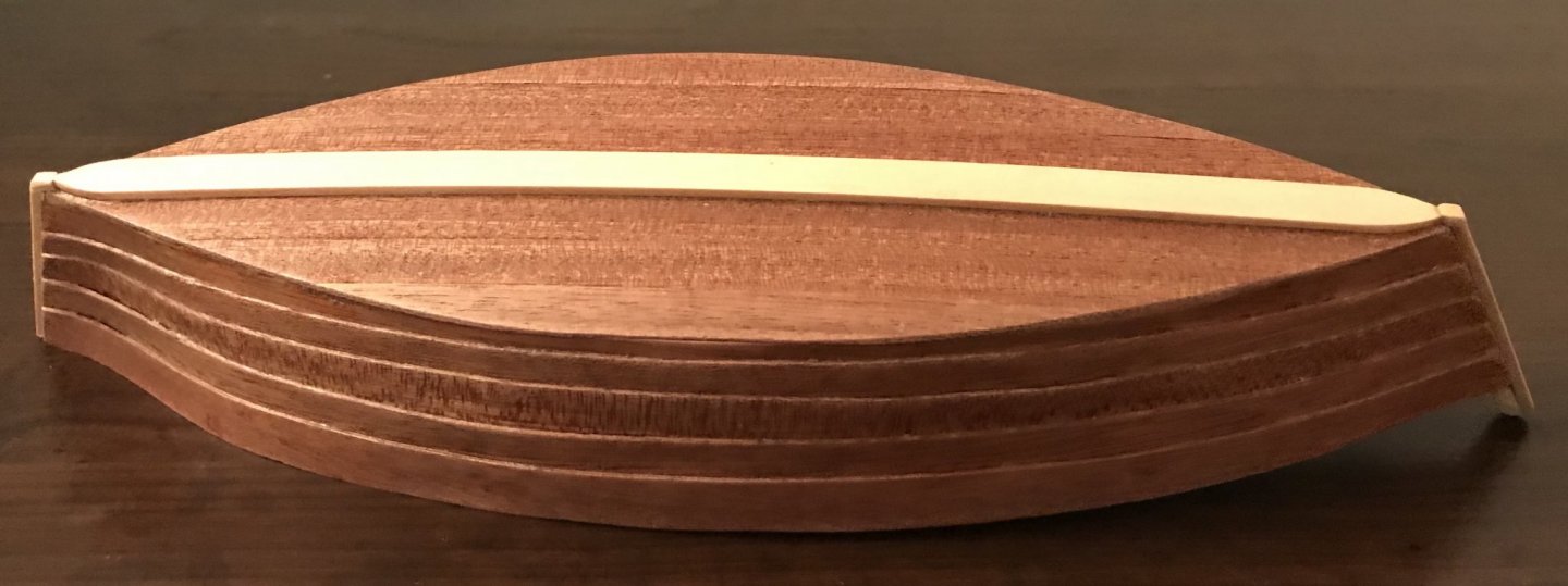
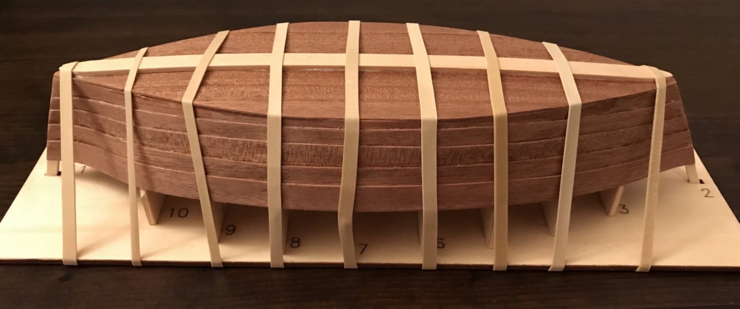
I've worked on steps 3, 4, and 5 over the last few days. Step 3 involved sanding down the frame in preparation for planking the hull, which is step 4. After smoothing things out, I laid the first hull strake on each side. The hull is planked in sapelli wood on both the sides and the bottom The instructions provide clear measurements at the stempost, midpoint, and stern—10mm, 5mm, and 10mm from the bottom, respectively. After measuring, soaking, shaping, and glueing the strakes in place, I sanded off all of the excess that went beyond the bottom piece. You'll note in the previous pictures that I've marked out the placement for the next strakes (well, at this point I had forgotten to measure the marks for the midpoint in the first photo!). Throughout this step, the measurements in the instructions are very clear and easy to follow. This is a clinker hull, so these measurements allowed me to have a very precise amount of overlap from one strake to the next. Since the scale is so large and the real boat so small, there are only five strakes per side. The sanding comes later, so the stempost looks pretty raggedy. I trimmed the strakes at both the stempost and the stern, then did enough sanding to make the job easier later. Step 5 involves planking the bottom and adding the keel. In the photos above, you might be able to make out the lines I pencilled in as guides for the seven strakes on the bottom. The curve is so gentle and slight that I didn't worry about soaking the strakes, I just went straight to glueing them into position, then used rubber bands to pin them down. Once those were set, I trimmed the strakes and did a lot of sanding. After sanding the strakes down to the shape of the bottom piece, I sanded the sides and bottom of the hull, as well as cleaning up the stempost and sternpost. Continuing step 5, I added the keel. The keel piece is actually about 4mm too short, so I centered it as best I could and am planning to add some 2x3x2 pieces from the strake used for the stempost and sternpost stiffeners. The rubber bands in these photos are holding the keel in place while the glue dries. The last part of step 5 will be removing the boat from the frame base!


- 12 replies
-
- 3
-
-
- la provençale
- artesania latina
- (and 1 more)
-
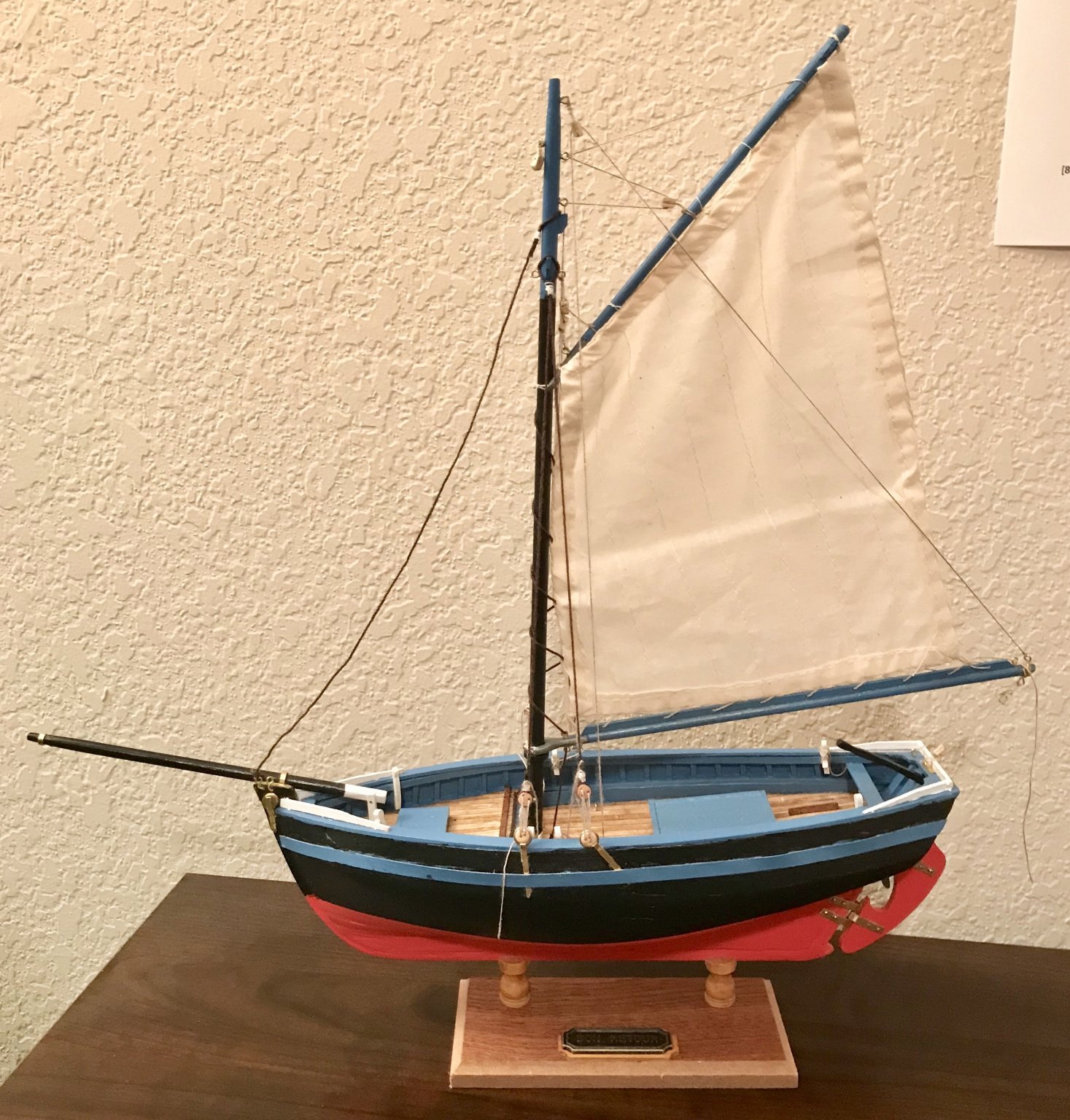
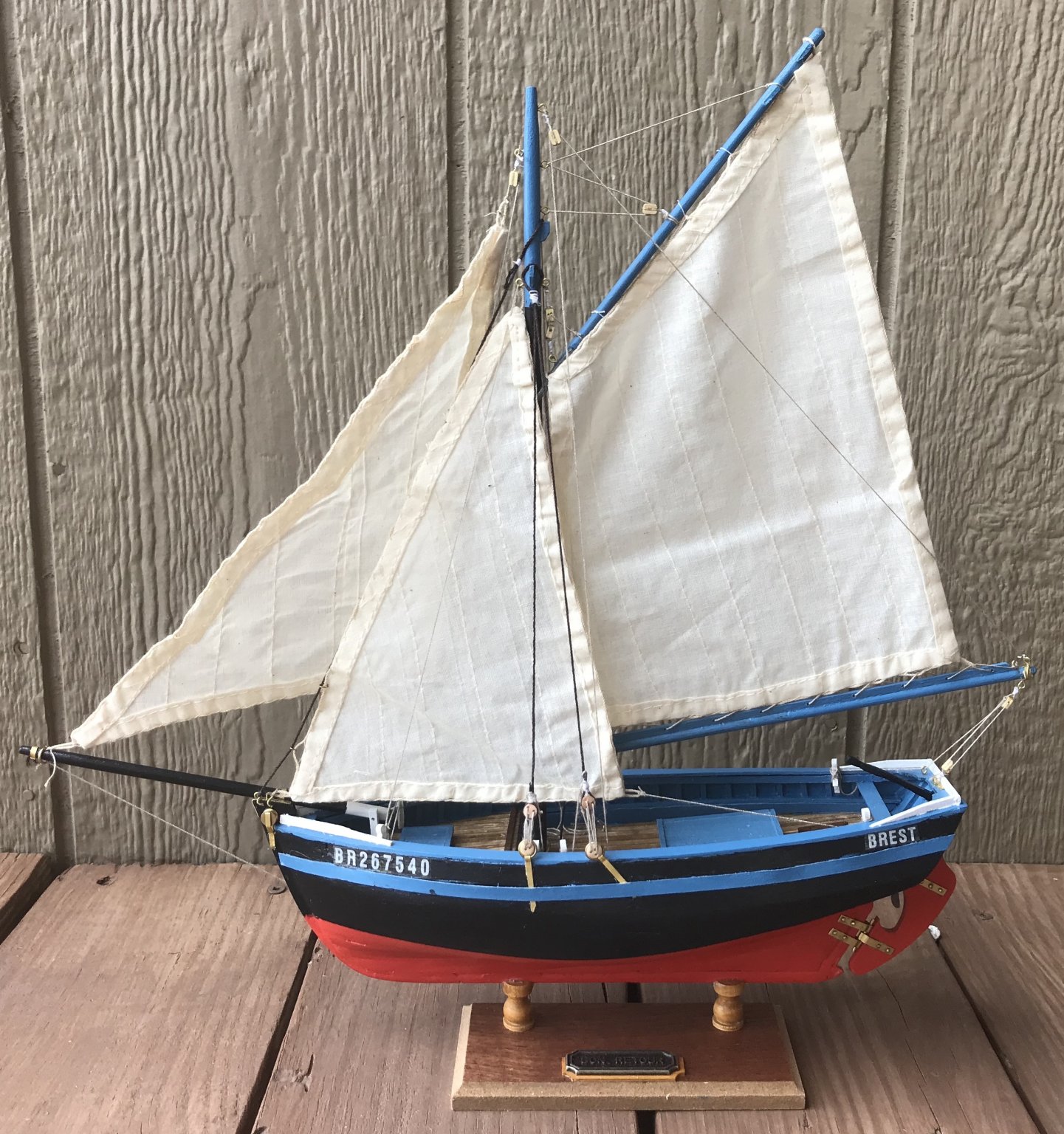
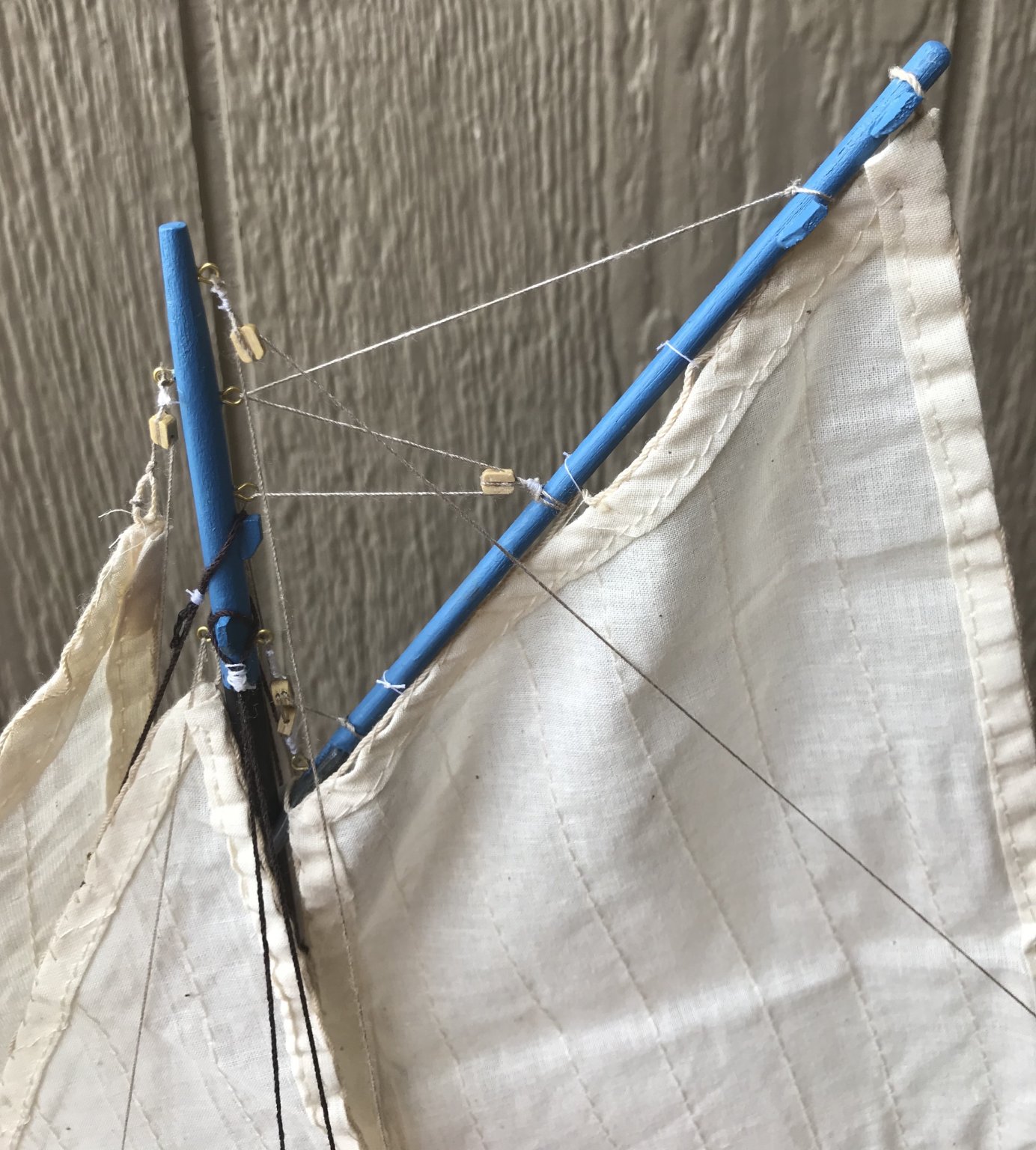
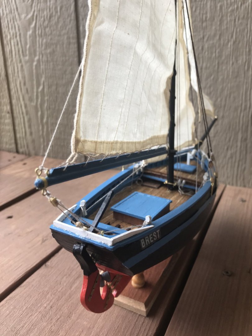
Okay, well, two days ago I declared that I was putting the Bon Retour on hiatus. Then I watched two YouTube videos on gaff rigs (from "How to Sail Oceans" and from "Living with the Tide") and, on the advice of Wefalck and Roger Pellet, read the relevant chapters of Tom Cunliffe's Hand, Reef, and Steer. Suddenly, everything clicked—the terminology made sense, I understood the logic of rigging, and I could picture in my head how the Bon Retour's rigging worked. So, after a marathon session last night and a few more hours this morning, the ship is finished! A keen eye will spot the faults that come from my inexperience. The luff of the jib is the part that bothers me the most; I just couldn't get enough tension on it. Some of the blocks and seizing are sloppy (I replaced two while rigging everything up). My coils are not as tidy as I would have liked. But I'm very pleased with how I did on the gaffsail. All of the rigging for that worked correctly, so once everything was on the mast, I raised the boom topping lift, then hoisted the gaff using the throat and peak halyards until I got a little bit of a crease running from the peak to the tack. Here's a photo from the end of last night's marathon, which was spent working on the shrouds and the gaff. This morning, I did okay with the foresail, though had to replace the forestay, since it was just too slack. The jib was the real challenge and I'll have to keep learning more about that—though I think the angle of the bowsprit may be the culprit there. But now some celebratory photos after finishing the rigging and placing the registration decals. First up, the view from the port side and the starboard side: Next a detail of the rigging at the top. And a few different angles looking onto the deck: Thanks for following along!


- 16 replies
-
- 5
-
-
- bon retour
- artesania latina
- (and 2 more)
-
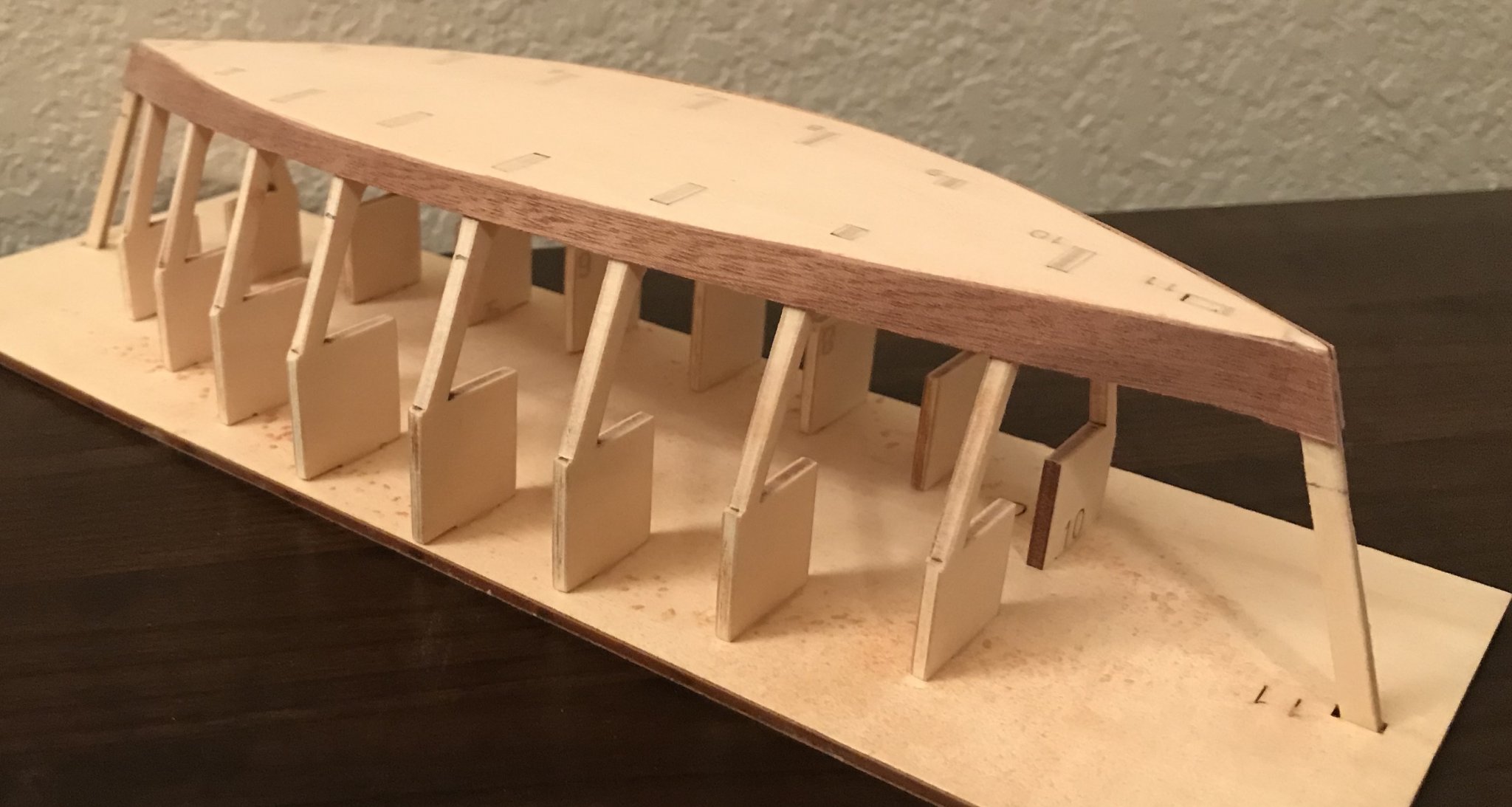
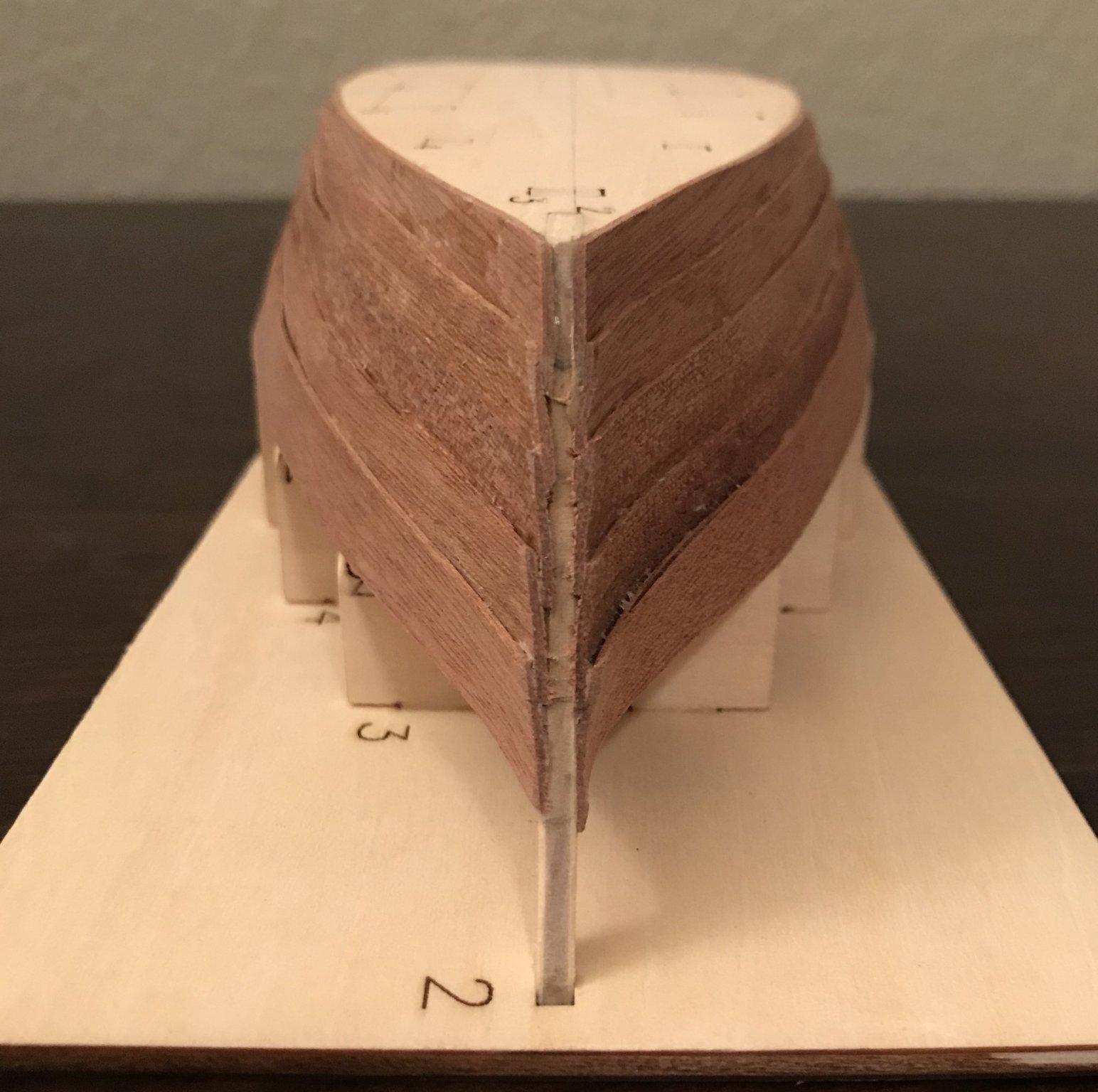
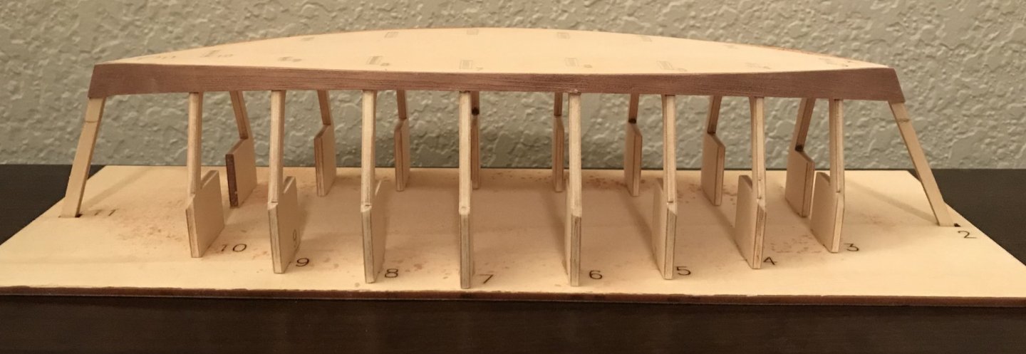
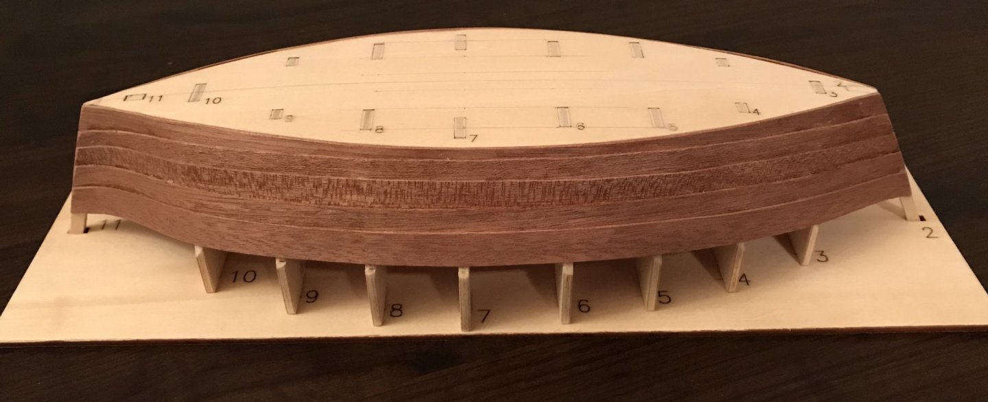
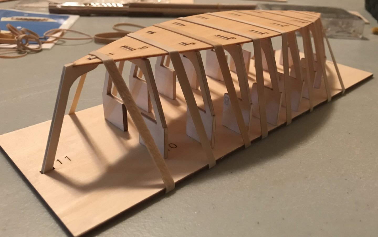
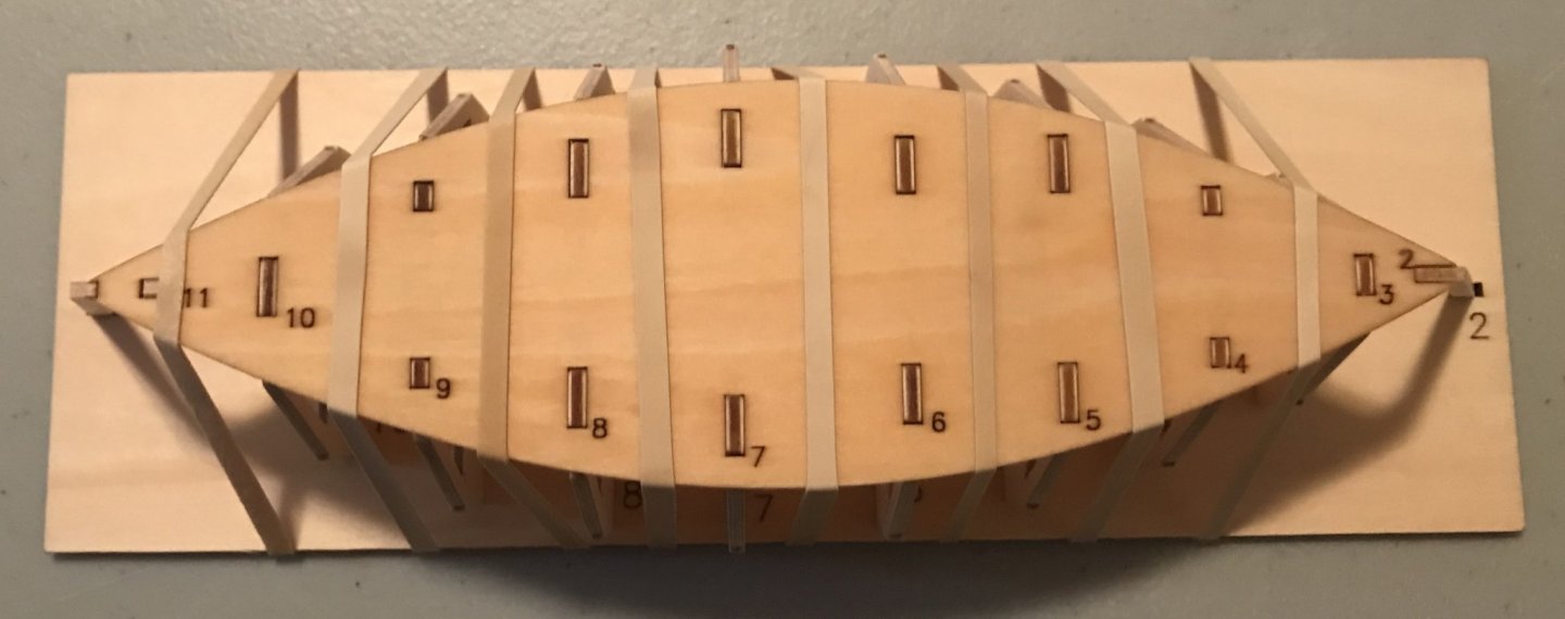
Steps 1 and 2: building the frame and fitting the hull. The Provençale is built using a frame base. After sanding the frames down, I dry fit them to the frame base. There are nine ribs, numbers 3 through 10, along with the stem and stern posts. After carefully aligning them using a square and dry fitting the hull, I attached the hull on top. With my previous kit, the Bon Retour, all of the parts were cut generously and needed some careful sanding to ensure a good fit. With this kit, however, the hull fit perfectly with no additional work. One more sign for me, along with the great instructions, that this is a better kit for the raw novice. The hull does need to curve a little bit, so to play it safe, I soaked it and pinned it in place overnight with rubber bands. The wood is still wet in the photos. It really seems to me like the numbers in the hull ought to sand out at some point, but they are etched pretty deeply by the laser. The bottom of the hull will be planked, so I made sure to put the numbers on that side, knowing they would be covered soon.

- 12 replies
-
- 3
-
-
- la provençale
- artesania latina
- (and 1 more)