xodar461
-
Posts
172 -
Joined
-
Last visited
Content Type
Profiles
Forums
Gallery
Events
Everything posted by xodar461
-
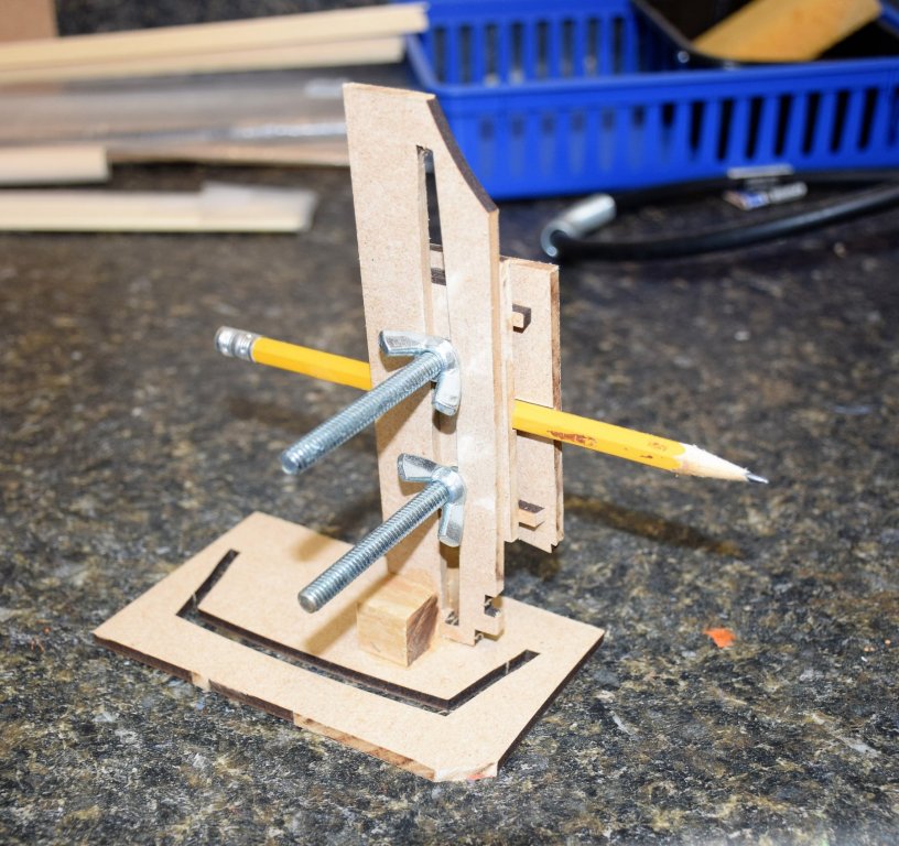
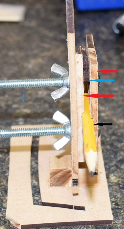
 now for a slight digression. My final plans for display when the ship is complete require a waterline. Rather that buy a marker (amati makes one and another is available from Hobbyzone for $8), I figured I could build one from the scrap from this kit). The base is from a 5 mm MDF pallet that held one of the min deck beams. The upright is another 5 mm MDF piece that held a beam. I had to make it wider to support the bolts and wignuts. the holder for the pencil - 2 more scraps pieces (red arrow) with a grove carved out to hold the pencil (black), 2 holes drilled for the bolts and 2 support pieces between the 2 pieces that hold the pencil (blue) when the planking is complete, I'll show a few pics of the waterline it produces
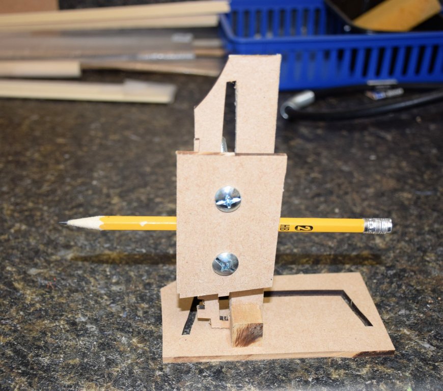
-
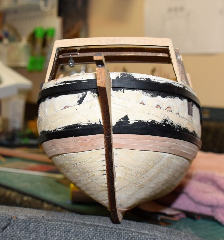
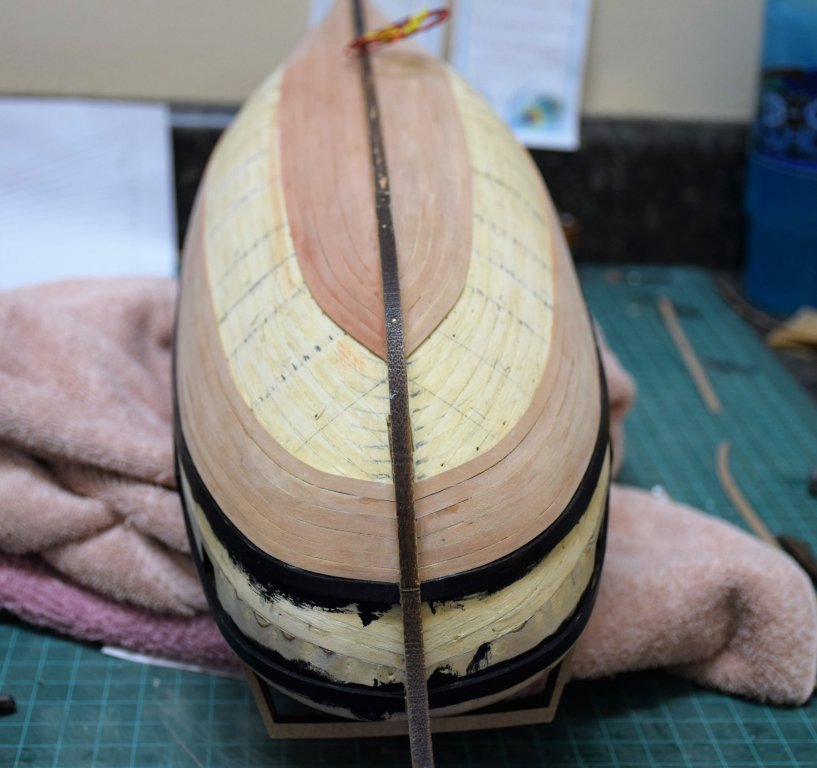
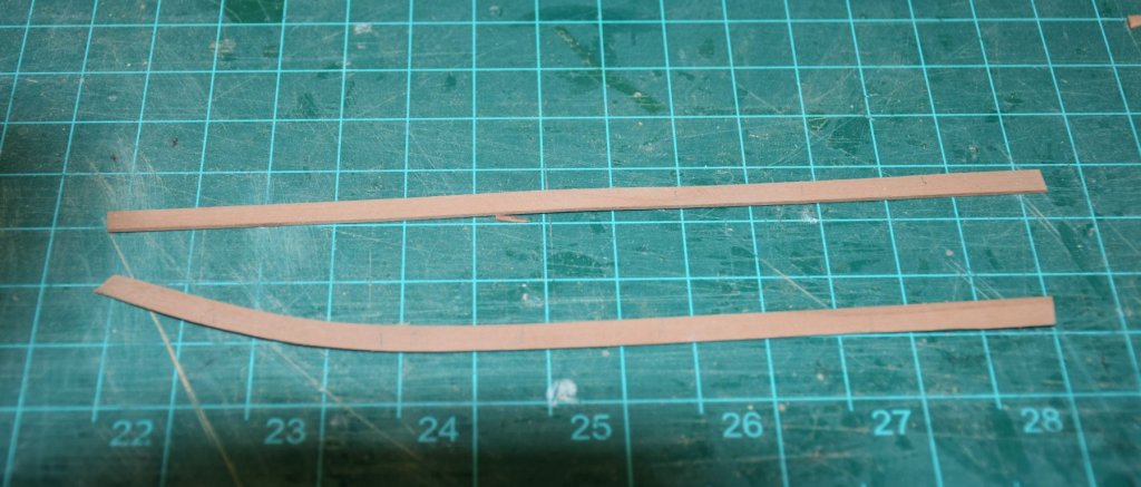
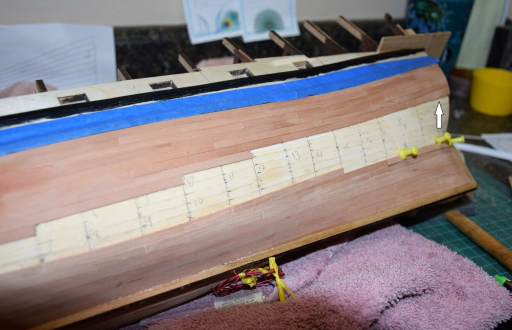
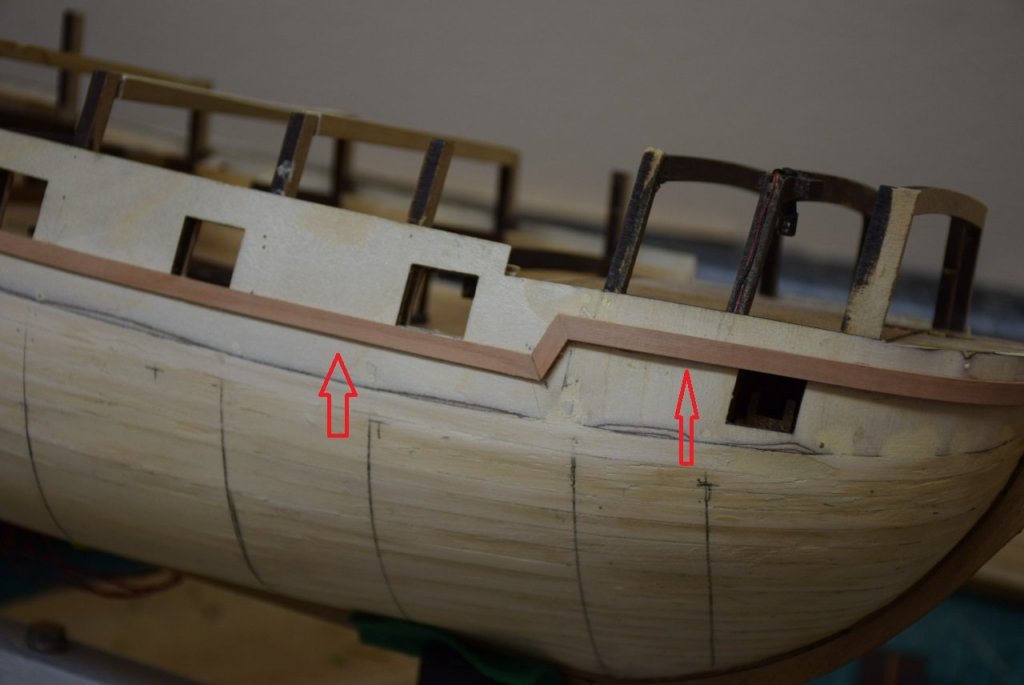
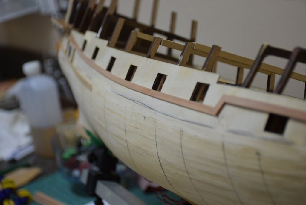
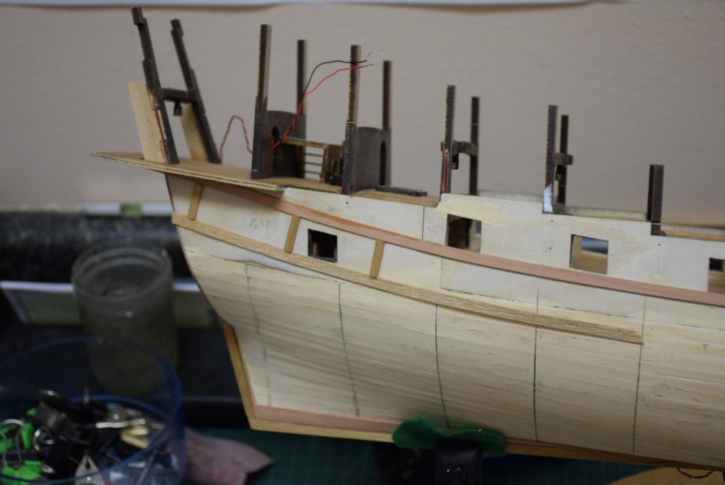
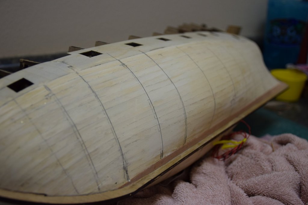
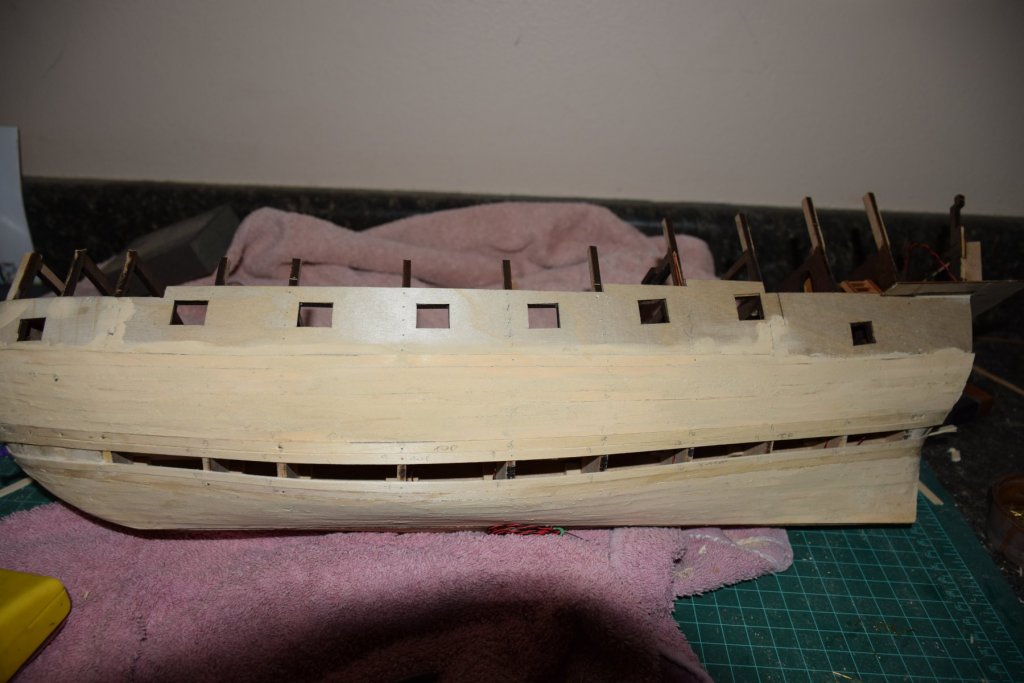
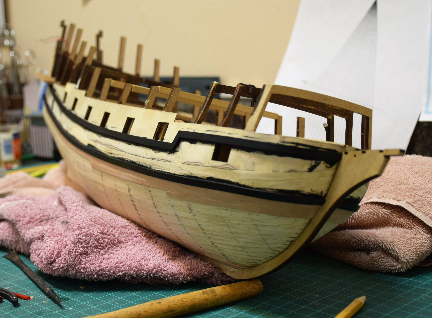
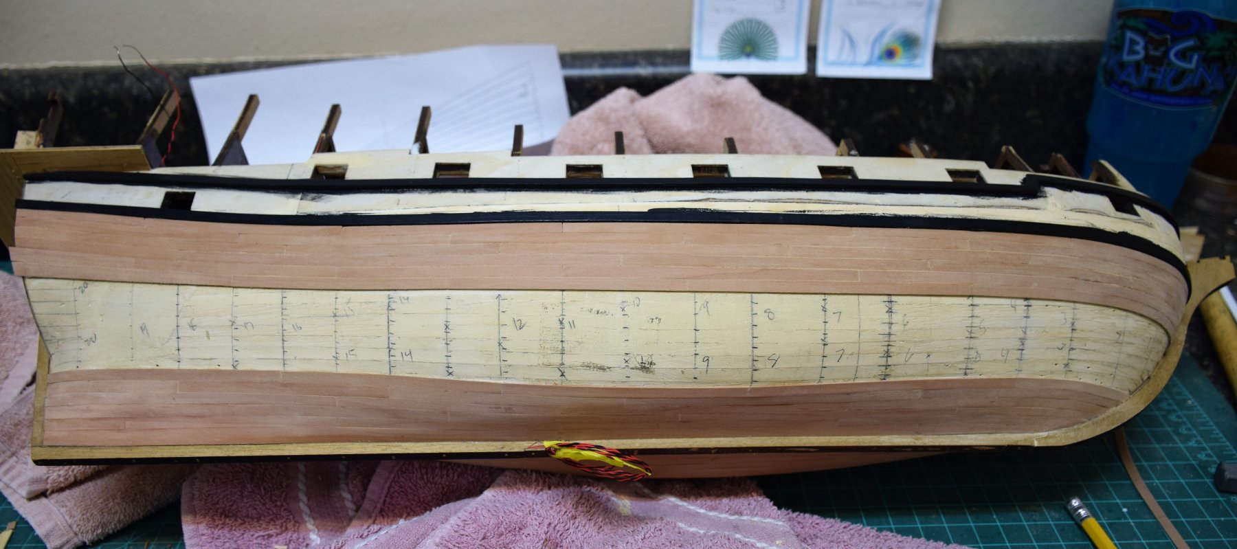
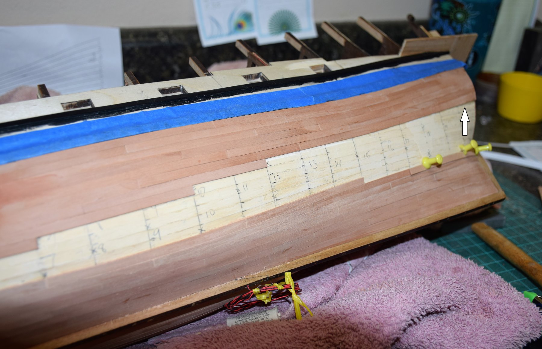
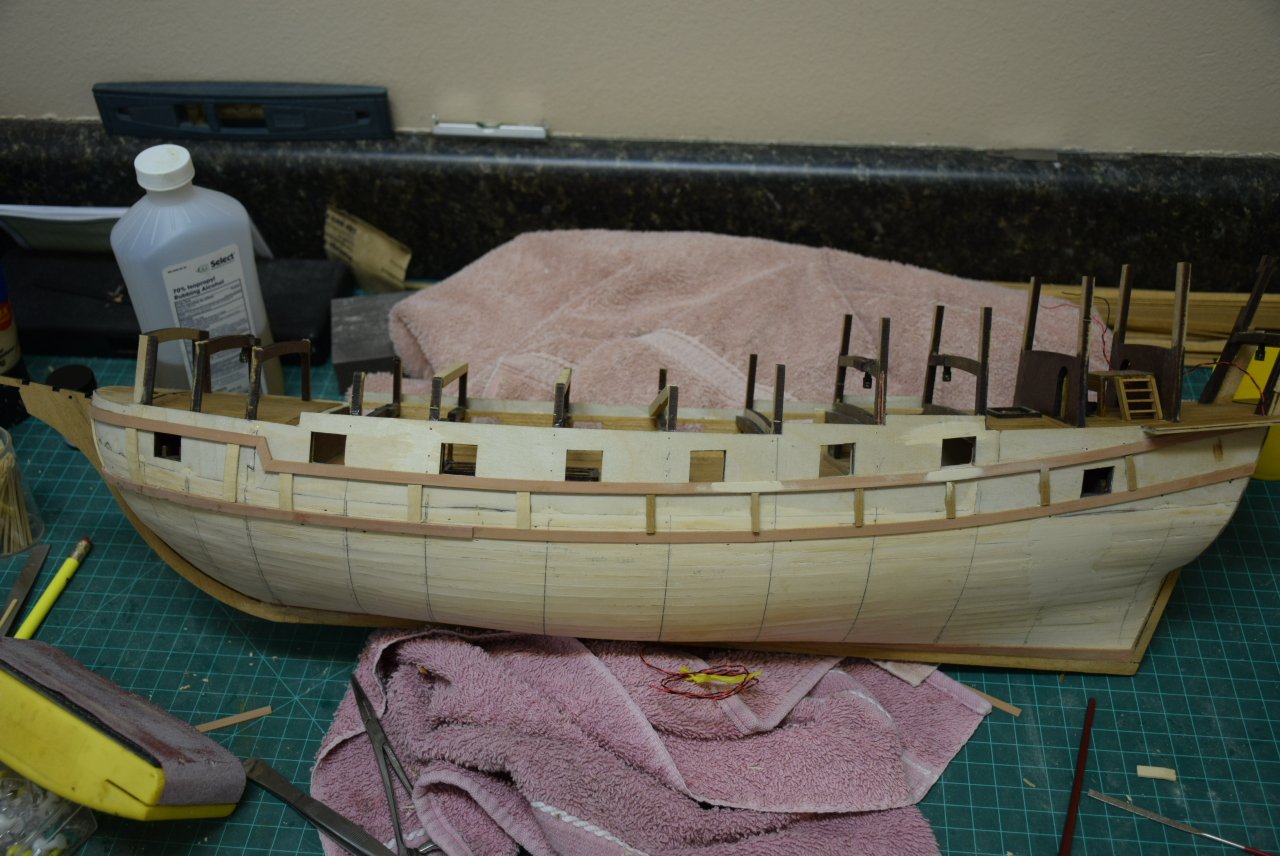
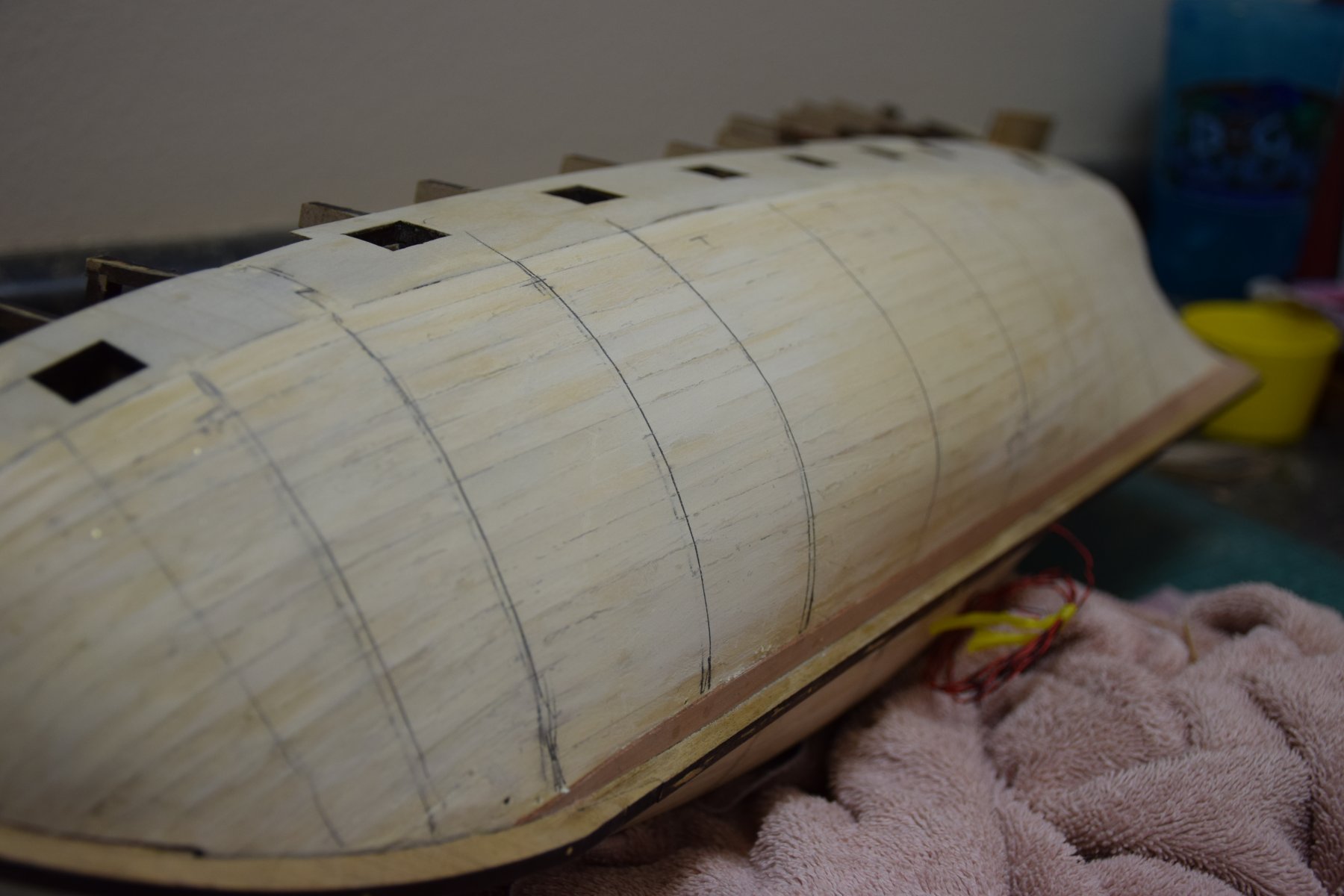
With the lower 2 wales complete, it is now time for the second layer of planks. As noted previously, 1x5 mm swiss pear was used. First pic is shot from the bow with the first few planks placed. A few more strakes placed. I am working from the wales down and keel up. The numbers on the lower layer denote frames (a few extra added to account for the butt joints) and the tick marks along each frame denote the plank width. I did not lay each plank the full length but rather used planks that are between 20-24 ft in scale (~4 inches) This next photo shows what can be done with swiss pear a little water. The curves at the bow are pretty extreme. Next is a shot of the stern as the planking progresses. Calculations showed that the plank width at the stern is wider than the 5 mm I was using. Rather than using stealers, I decided to use 1x7 mm swiss pear and trim to the appropriate size (white arrow)


-
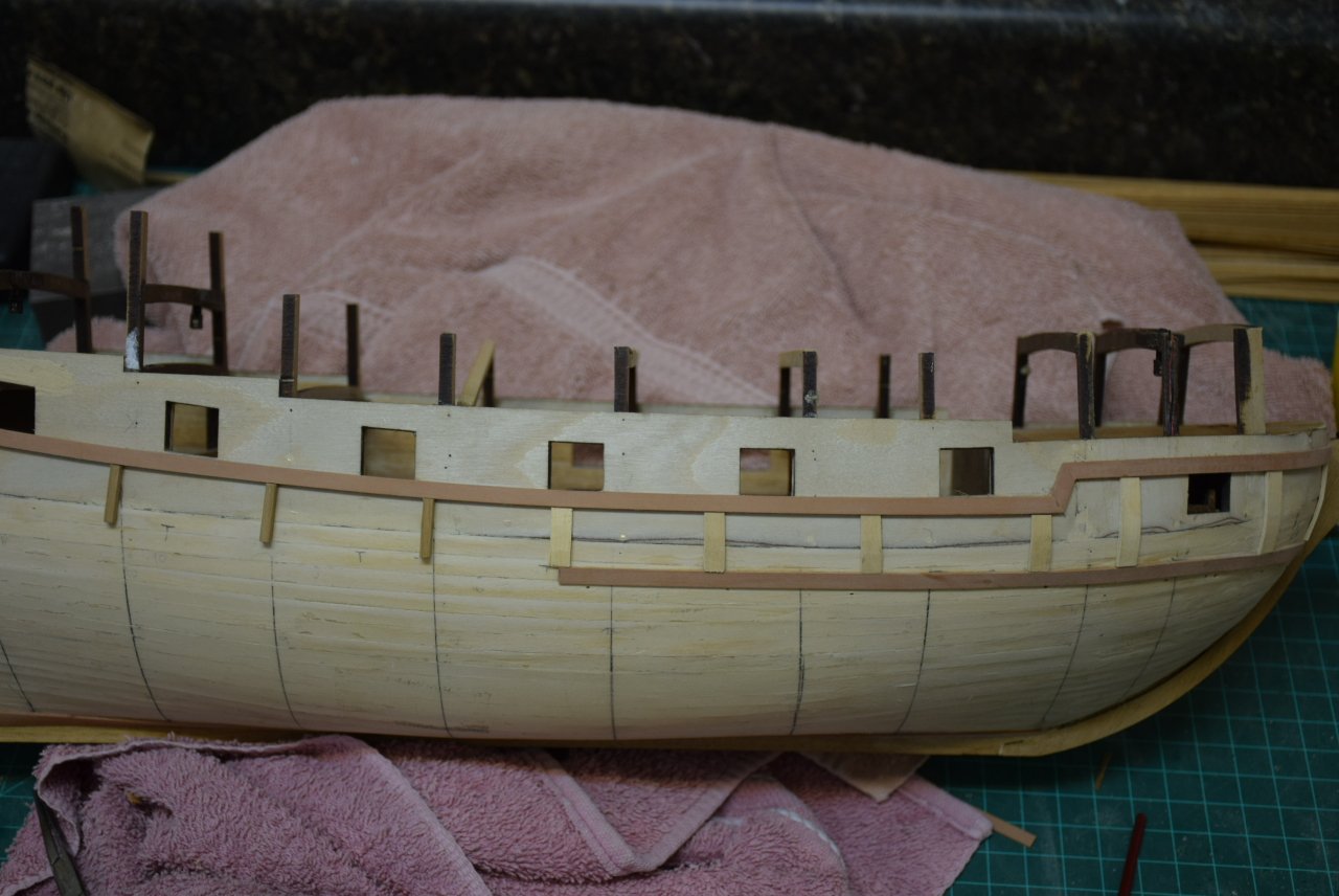
The plans call for the first plank to be laid down is the main wale. This required measuring down from the gunports, making marks where appropriate. While this was simple enough amidships, it was a bit difficult to estimate where the wale should fall at the bow. so I decided to place the upper wale first. this one follows the lower edge of the gunports and it's position at the bow easy to figure out as the forward part is staggered and follows the upper edge of the foremost port. Also, instructions say to lay the planks then add another 1x5 strip on top , then paint, to make the wales. I decided to make both wales first and paint. The lower wale was then placed. The distance between the wales in constant from bow to stern. Spacers were used to maintain this distance. You can also see the difference between the wood supplied with the kit and the Swiss pear that I will use. This last photo shows the first 1x5 plank placed and part of the second plank on top of the first to make a wale on 2x5 mm. Next up, the wales will be painted and the on to the second layer of planks Jeff


-
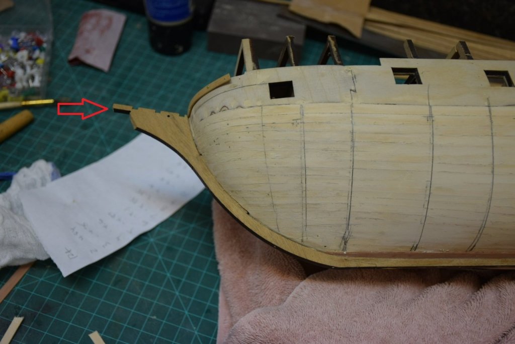
Greetings! Prior to beginning the second planking the stem and keels must be fixed to the hull. I used some long brass nails for some extra security for the keel. Could not really do this with the stem as they nails will be visible, however, once the planking is set into the stem's rabbet, it should be secure enough. The frames are also marked to help with the plank butt joints This pic shows the keel this one shows the rabbet at the stem and this shows the stem. Not sure how other builders of this kit managed to complete all of the second planking without breaking the stem as it is rather long and seems a bit brittle. Mine broke off before I even had the wales on (red arrow). Not a big deal as it should be easy enough to glue back on when the time is appropriate
-
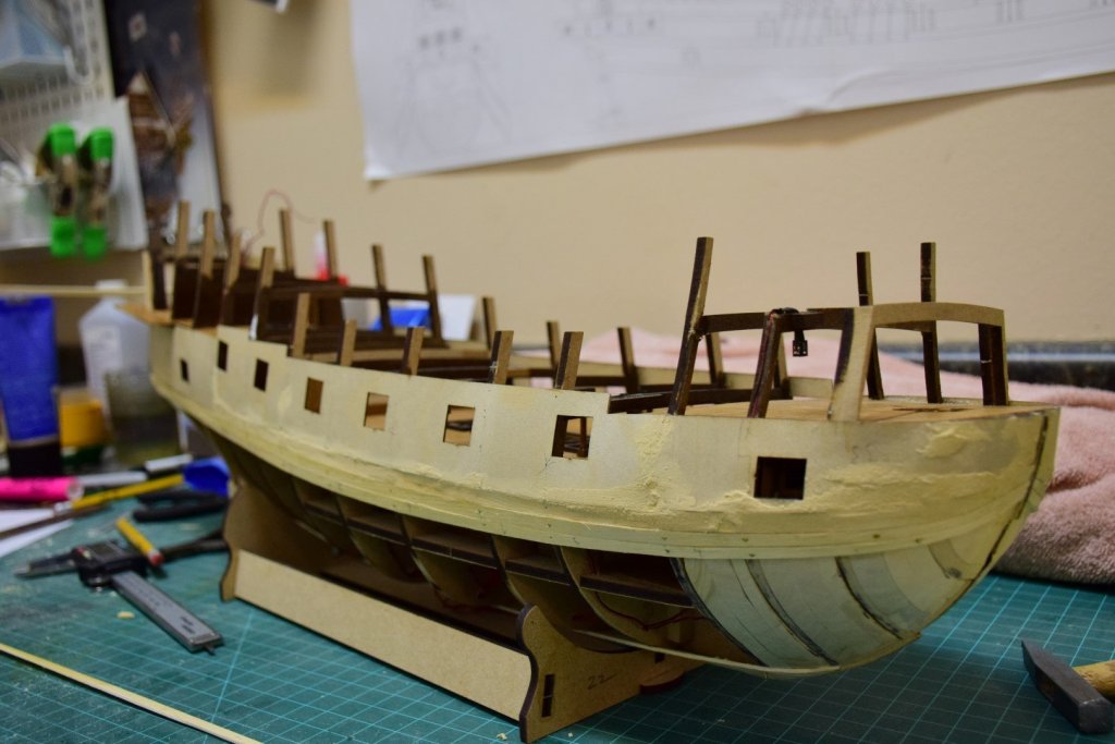
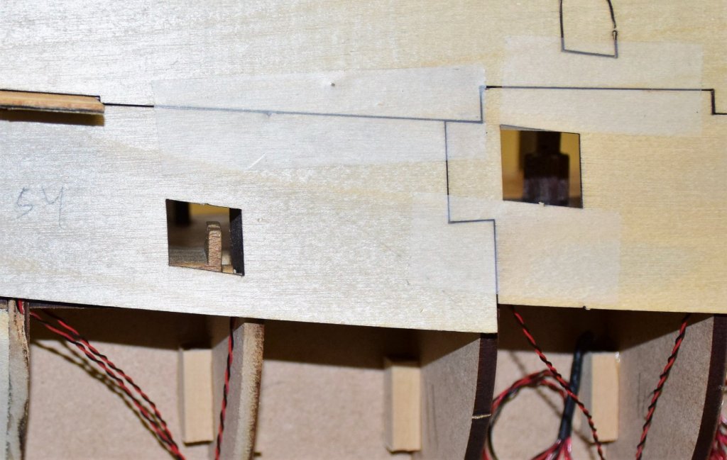
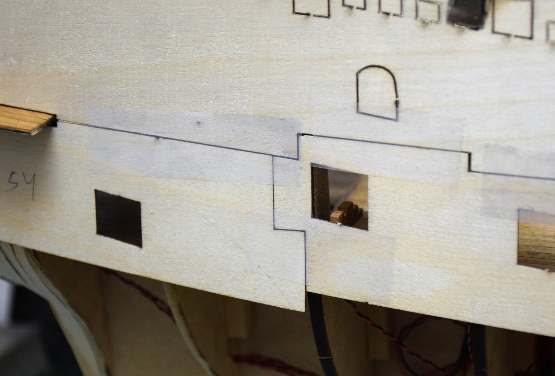
while doing all this internal work it became evident that the aft most gunport on the lower deck would be a problem for clearance of the cannon on the lower sill. As can be seen in the pic below, there is minimal clearance already and a 0.5 mm gunport sill has yet to be added. Seems to me that there should be a slight step up in the deck from gunport #6 to #7. This issue was briefly mentioned by Emelbe in his build log. His solution was to build a small platform for the gun to raise it up. Not entirely satisfied with that fix, I decided to raise the entire deck 2 MM. Last photo shows a cannon after new deck installed. Much better and now should have no problem placing a 0.5 mm sill Next up will be the second layer of planking. Not going to use the kit supplied wood as it is the same type as the decking and seems too brittle for the hull planking. I've decided to use swiss pear from crown timberyard which hopefully will give a better result. Jeff
.thumb.JPG.73d5bc9ee7a94ccf9bb9cffb2a40eefe.JPG)
.thumb.JPG.dcabeeaef73c5f23b23001504aff3a01.JPG)
.thumb.JPG.0c29b431949dc6e6a3a4e37b6b482b6d.JPG)
-
The lower gunport patterns have gunport frames glued to the inner aspect of the pattern as can be seen below Although this area will be covered by the upper deck, I did not want to leave them like this as I planned to secure the cannons with not only glue but rigging. This would require some internal planking. First step was to add some deadwood to the internal gunport pattern. I used some MDF from the same pallet that the gunport frames came from. The ships frames were still a bit wider so some planks from those used for the first planking layer were used to make up the difference. Finished...
.thumb.JPG.d9835fb88fe3b7c4a26f45b7df4543e6.JPG)
.thumb.JPG.8f43eef46f9a746e80cc27e3b5301cf5.JPG)
.thumb.JPG.9cb8d9425c1f2b09453cc2ca0b0b16d6.JPG)
-
After the lower gunport patterns are in place, it is time to lay the first planking. Here are a few photos of the progress. no real problems encountered at this stage. Photos also show a bit of wood filler used to smooth out some areas where the planks join the port patterns. Almost done First layer finished. It was very helpful to have the bow (up to frame 4) and stern (frame 13-14) filled with wood to allow extra purchase for the planking. Photo seems to show some unevenness to the planking but is is actually quite smooth as can be see from the bow and stern shots Stern planking using a pattern supplied in kit
.thumb.JPG.7c9e34cb32fd5957d2dbc685c5489ea7.JPG)
.thumb.JPG.72f0ffef7fc44f0634a82a02eb425d2d.JPG)
.thumb.JPG.49ed0adefc0bc63eee40192d9f8829a4.JPG)
.thumb.JPG.d4d4ab92a26dda348ec553bfcfd67e9d.JPG)
.thumb.JPG.ec9abcbfd8c2f40001cea879804f62da.JPG)
.thumb.JPG.13ac16d2d6b2b7c2ebe5984c9421b21e.JPG)
-
I am currently building the Revenge by Amati and I wonder if someone could help with a question regarding pliability of holly or swiss pear. The kit is double planked and requires some complex curves at the bow, especially for the wales and upper strakes. The wood supplied is some sort of walnut, 1x5 mm, and not really suitable for bending along its edge, even with soaking in water or ammonia. And I really don't want to make these planks with spiling (and after watching Chucks's videos, seems like you don't really need to do this anyway if you have the right type of wood) I have some 1x4 mm Holly and this wood is so pliable I can bend it along its edge quite a bit without breaking (almost 90 degrees). The same is true with some 1x3 pear wood that I have. So my question is this: can a slightly larger plank of pear or holly, say 1x5 or 2x5, be bent just as easily without fracturing? I am thinking of replacing the hull walnut with pear and would like some advice before I put an order in with Crown Timberyard. Unfortunately I have neither of these sizes to test at home and the 1x4 holly is a bit out out scale for hull planking. Thanks, Jeff
-
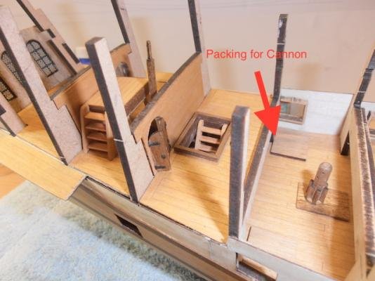
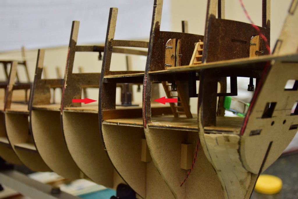
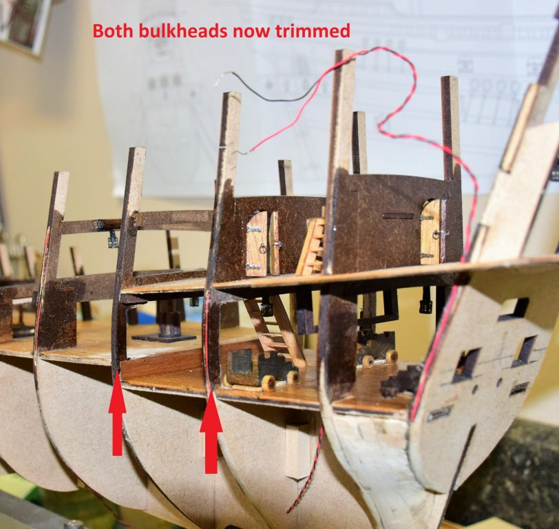
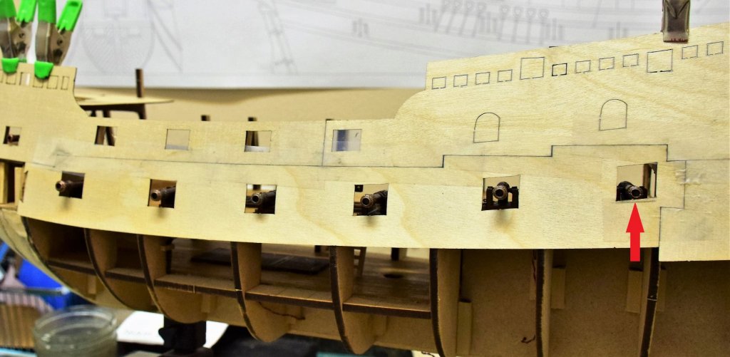
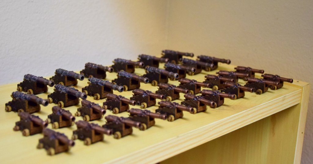
After a long interlude...Several cannons need to be fixed in place prior to placement of the side gun port patterns. 2 small cannon carriages are placed at the stern. No issue here with the barrels temporarily placed the plans call for one small carriage at the bow. Problem here is that in the picture of the finished model on the box, this cannon seems to be a large one and there is no way it will fit in this space and be centered in the port. This one is on the same deck as the other large cannons. I ended up using a small one here as the instructions say to do. So I will be short one small and have one extra large. Not an issue now, but easy enough to deal with...just could have one port closed. next issue was the 2 large carriages towards the stern. When placement was tested, the bulkheads interfered with centering of the cannon in the port. next 2 photos illustrate the problem. The fix was easy enough...trim back both bulkheads in order to make them more like frames. Luckily, the MDF is muhk easier to trim than plywood! Since i had to make a few small and large cannons, I figured I may as well make them all. This way I can test cannon placement with the gunport patterns. one of the aft ports was a bit off so about 1.5 mm was taken off the lower edge. Before trimming, I checked that this would not affect the wales as one comes close to this port. Should have room to spare above the wale. The cannons... Next step is to affix the side gun port patterns. Jeff


-
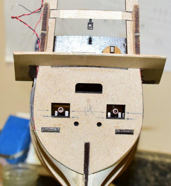
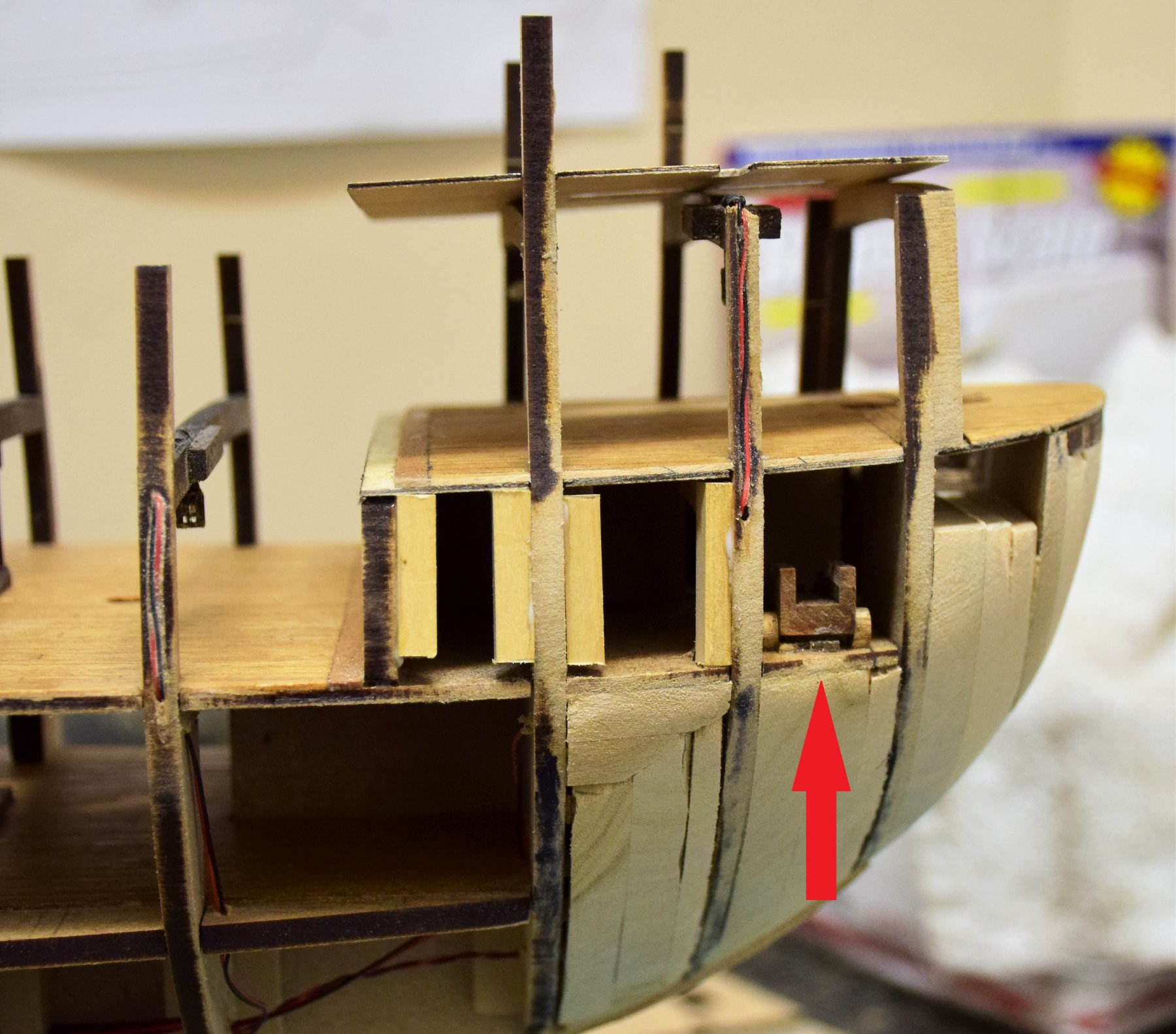
Work on the lighting now complete. All the wires have been joined together with the one lead wire exiting from the keel. This will be eventually connected to a 9 volt battery in the final display. It will be interesting to see how much is visible when the ship is planked. Red arrow in second pic shows an LED meant to represent a torch. The LED wont be visible, only the flickering light will be through the hatches Here are a few pic of the helmsman's platform and whipstaff assembly. And finally, I decided to add some filler wood to bow and stern - basswood of a variety of thicknesses - showing one side sanded and the other still rough. Stern has been mostly sanded to shape Next up - a few cannon carriages have to be fitted before any side panels are placed. I may rig the ones at the stern. Others nay be a bit difficult to rig based on their location. Jeff
.thumb.JPG.291ce192931fe6a25a75451f84e21152.JPG)
.thumb.JPG.bb7b38465c2fac58db648bb2691d3b5d.JPG)
.thumb.JPG.5b5175a2d795caf258bff4eff59091f7.JPG)
.thumb.JPG.a6f2ad3fe477a806d0df6d761369d6d4.JPG)
.thumb.JPG.053e6d5e209b3cfaa6b41c511da51f66.JPG)
.thumb.JPG.4e3070ec2b671e8739ad1534631edc96.JPG)
.thumb.JPG.ebb44cbf4a4107828951154533b277dd.JPG)
.thumb.JPG.f17df626adb77a9b8c4637638f54e580.JPG)
.thumb.JPG.9a1e211f9c89a7d3d3a46d43cf940c72.JPG)
.thumb.JPG.8a9ddcb8ae8e150201086f5f940e687d.JPG)
.thumb.JPG.6628614c6ddf910888853c83218e7ffa.JPG)
.thumb.JPG.8a94f058bbe6bcdb28ea57479bb4ec2f.JPG)
.thumb.JPG.dc044462c8c604287252a33e2f703b10.JPG)
- 159 replies
-
- 11
-

-
Past few weeks have been spent installing the below deck lanterns. I decided to add a light to each one to hopefully illuminate some of the work done in the lower decks. The light s are 1.8 mm orange LED that flicker to simulate a flame. To hang the lanterns a hole is drilled in the corresponding beam with some support wood on either side as the hole will weaken the beam. I then gouged a small trough in the beam to fit the wiring. The wires were then run through the beam and down a trough in the frame to exit beneath the lower deck. The photos illustrate some of the work. Below is an LED test fitted through the beam and frame A close up on one lantern: Wiring complete for this one: Multiple lights installed. lots of wires! A total of 10 lanterns and 4 LED "torches" will be installed. All can be run with a nine volt battery. Jeff
.JPG.cbde12aa1dbf58a3664d7085099fb19e.JPG)
.thumb.JPG.7d45833360839753e4f782f5b8f0cb82.JPG)
.thumb.JPG.c974e00b625e52c4b0e35455fa90dc9c.JPG)
.thumb.JPG.84f4f8d4d4c2e5dd16431e3aa962ea0a.JPG)
.thumb.JPG.6b14b00daf9ead98b3b2fb82aed1c5e3.JPG)
.thumb.JPG.e26158b44a489a15089c64c2e4436a2e.JPG)
- 159 replies
-
- 12
-
-
I would like to know if any builder out there who have completed Amati's Revenge 1577 kit have any spare lanterns that were not used during construction. I am adding light to the interior of the model and I would like to have a few more than the ten supplied. Here is a photo : Here is what I am doing.. The LED flickers to simulate a flame. Send me a PM if you have any to spare Thanks, Jeff
.JPG.9f7911284f2ec47ddefe37a904a9ea26.JPG)
.thumb.JPG.b216d6789225232d0adb41f63ac81440.JPG)
-
- 2
-
-
More decks now planked and installed. Main gun deck, bow deck, raised lower deck and rear deck. I decided to use a softer graphite pencil (#9) to simulate the caulking as a standard #2 was a bit light (note the difference between the main gun deck and the other decks at this level). The bow deck was partially planked and then installed as it has to be bent to insert down the frames. Grating frames are left open for now. Still not sure if i want to use the etched brass. The next pic shows more beams in place to support the upper decks as well as the aft most frame #14 now installed with the bare upper stern deck. Beams 6B, &b are half frames with support columns. This is one piece in the kit and the support column was not that good. Here is one from the kit and my replacement. The foot of the handmade column is longer than the kit as the beam sits in a square hole in the main deck. If the foot of the column was as short as the kits version, the round part of the columns would end at the deck. I made one that way before i realized that this would not be a good look Here they are installed: A ladder is installed from the main to the lower deck: And finally, a few pics of the whipstaff assembly, capstan and rear gallery deck planking. The tiller arm is temporarily inserted to show how the whipstaff will connect to the rudder. So far no more surprises. The gaps in the planking on the side galleries are to allow fitting of the side patterns. It will be important to get them correctly positioned as they determine the height of the gunports from the deck. I will show some pics with a few cannons in a future post. I also plan to fill the bow and stern with basswood that will allow for a better purchase of the hull planks. I also plan to install some lighting in the lower decks as all this work will be invisible one the upper decks are in place and the hull is planked. The kit comes with some PE brass lanterns and I hope to be able to put the light in them and run the wires through the frames and out near the keel. Here is a link to show the the kind of light i am taking about: https://www.modeltrainsoftware.com/flickering-led.html I will have to work out the lighting details before i progress much further with the build. Jeff
.thumb.jpg.3fb3a12b5ba723ab4136d74bcf15ea77.jpg)
.thumb.JPG.cfd1676923161c0a228ff62a0d1a0de3.JPG)
.thumb.JPG.7a35b3d7eeb070d61d0f602a3a1fcb2b.JPG)
.thumb.JPG.19760a5af108b4f5692b68e34abfe03f.JPG)
.thumb.JPG.a2a13a94f186db80b32f261f845ae7ed.JPG)
.thumb.JPG.9ddeb4dd99b5836c0ad2937890074e09.JPG)
.thumb.JPG.22fa2e02c88c6a230d0ca40fa260cc90.JPG)
.thumb.JPG.b50a4f504c41f37e1777601f77533848.JPG)
- 159 replies
-
- 11
-
-
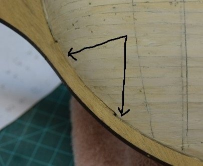
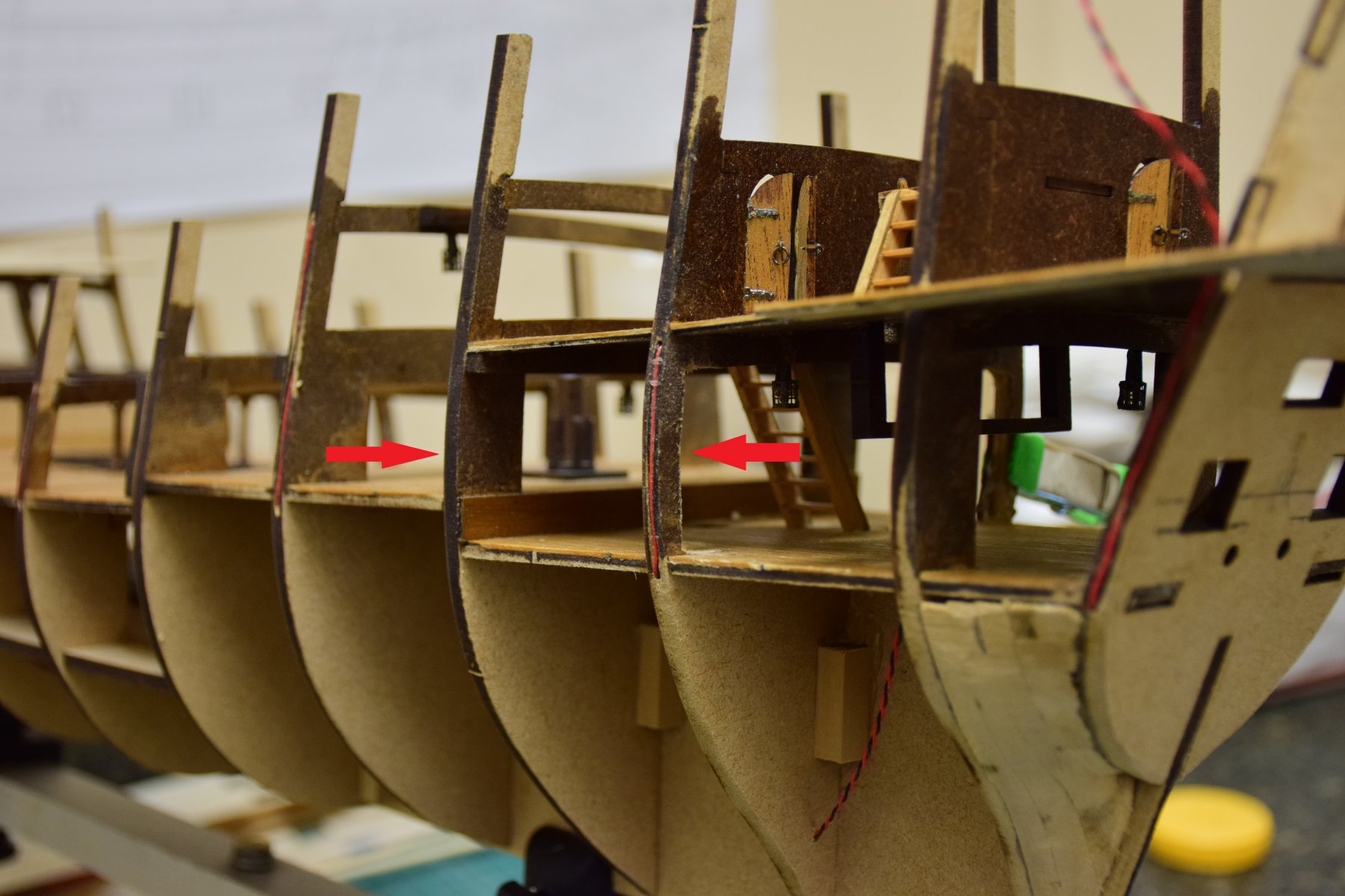
An interesting issue arose when i fitted the main deck after planking. It seems that the central part of frame 4 is too high. Before doing anything drastic, time to figure out what, if anything, may have gone wrong. here is a pic to show the details the red arrow shows how much the frame is off. If not corrected, the main deck will not seat correctly onto frames 2,3. there are 2 decks that are fitted above this one and the alignment of those 2 seemed correct when I dry fitted them. Also, where frame 4 meets the bearding line seems OK too (yellow arrow). Here is a shot of the plan Looks OK here too. this is how the deck is seated with nothing done. Red arrows show the gap. As I could find nothing wrong with the alignment of the overlying decks or with frame 4 at the rabbet, I have to assume that the frame is off by a few mm in the area of the yellow circle - so this is what I trimmed down. now deck is seated perfectly along frames 2-4. hopefully I don't have to modify anything else as the upper decks go in. This is the planked main deck, not yet sealed with poly Jeff
.thumb.JPG.da8bf07be8d22057d1fdee5f147c8554.JPG)
.thumb.JPG.83bb9a816e87c0f81a571ad768f5325d.JPG)
.thumb.JPG.9fc2138bd9f0596046e56bcd7b6981e9.JPG)
.thumb.JPG.38b284bf187e43c83ee12a5e6f35980f.JPG)
.thumb.JPG.9378069b5397df9aca5a8a5489055936.JPG)
-
After the frames have been attached, the first deck to place is the orlop. Although the manual shows this as 1 piece, the kit splits the deck down the middle for 2 pieces - much easier to fit this way. The deck is planked off the model and then glued onto the frames. The hatch coamings and gratings are then fitted. As others have pointed out, the gratings are photo-etched brass and not wood. One problem with replacing them with wood is that the grating openings may not be to scale - often they are too big. As this deck is deep within the ship, it won't be too visible anyway so I'll decide later if I want to change out to wood for the upper decks. here are pics of the deck pre and post application of satin poly. I think the gratings are acceptable. Also note that I have decided to not use treenails to the deck. At this scale they would be barely visible anyway.
.thumb.JPG.dfe059a0207adafbe55903b6b1c18841.JPG)
.thumb.JPG.fec55d6a266375c4d302fdf4879a24e5.JPG)
-
Here the frames have all been fitted and glued. Only one frame glued at a time and the false decks were used to maintain correct alignment. The frames were also tapered at the bow an stern. Note that frame 1 extends pretty far below the curve of the false keel. This is because a slot is present to fit the stem. In order to get an idea of the true curve here, i fitted a think piece of scrap wood to the keel as you can see in the next 2 pics. This area is not well seen in any of the photos in the manual and one may think that more material need to be removed from frame 1. Nothing worse than finding out later that too much wood was removed!
.thumb.JPG.47e6a92d0c873b744b87b863ca71c33a.JPG)
.thumb.JPG.b0be54d1abea47ef3173df3382643395.JPG)
.thumb.JPG.0631928637dc19671b63617044eac9d8.JPG)
-
To start, I test fitted all the bulkheads onto the false keel. Nothing is mentioned in the manual re: cutting a rabbet but i decided to proceed. The stern has to be trimmed down otherwise it will be wider than the rudder post when the planking is placed. The lowest extent of each frame was marked and the rabbet was cut from was below the frame. Here is a pic from the stern: And here is the rabbet from frames 7-9.
.thumb.JPG.f3234637e20eb48d9051736a1148b803.JPG)
.thumb.JPG.6c784fdc1d49f6a2d7bada0a25aec60f.JPG)
-
The kit was well packaged and after inventory, I don't seem to be missing anything. The fitting seems decent enough though the blocks will have to go as they seem to be the standard kit block that are too square. There is a lot of photo etched brass with this kit, including the gratings. The backbone of the kit is made from something called MDF (medium density fiberboard). Had to look this up as I have never worked with it. Another type of wood that I had not heard of before is dibetou ( From the web: The heartwood is bronze orange-brown, with gum lines causing black streaks or lines. The grain is usually interlocked, but is sometimes straight, texture moderately fine to fine). It seems to have a rather delicate grain so I'll have to be extra careful in removing parts from the pallet so as not to split the part along the grain. Here is a photo:
.thumb.JPG.8641bbce049122ec6c1325fcd696555b.JPG)
-
Greetings. This is my first attempt at a build log, though it is far from being my first ship. Having recently finished HMS Kingfisher by LSS (see gallery), the Revenge caught my eye and I decided to have a go of it. For those of you who decide to follow along, please note that my work on models can be sporadic at times. I will try to post updates as I complete each page or 2 of the manual. Kit was ordered from Ages of Sail and here is what comes in the box.
.thumb.JPG.b502b12b698f33d9c520d313c72a58dc.JPG)
.thumb.JPG.2fb26fa28155bb95a2168493a9f220bb.JPG)
.thumb.JPG.ffdd5ae4c2bcec6ee2b201ba236a62a2.JPG)
.thumb.JPG.952986f5073ce021bc37794bd2de3114.JPG)
-
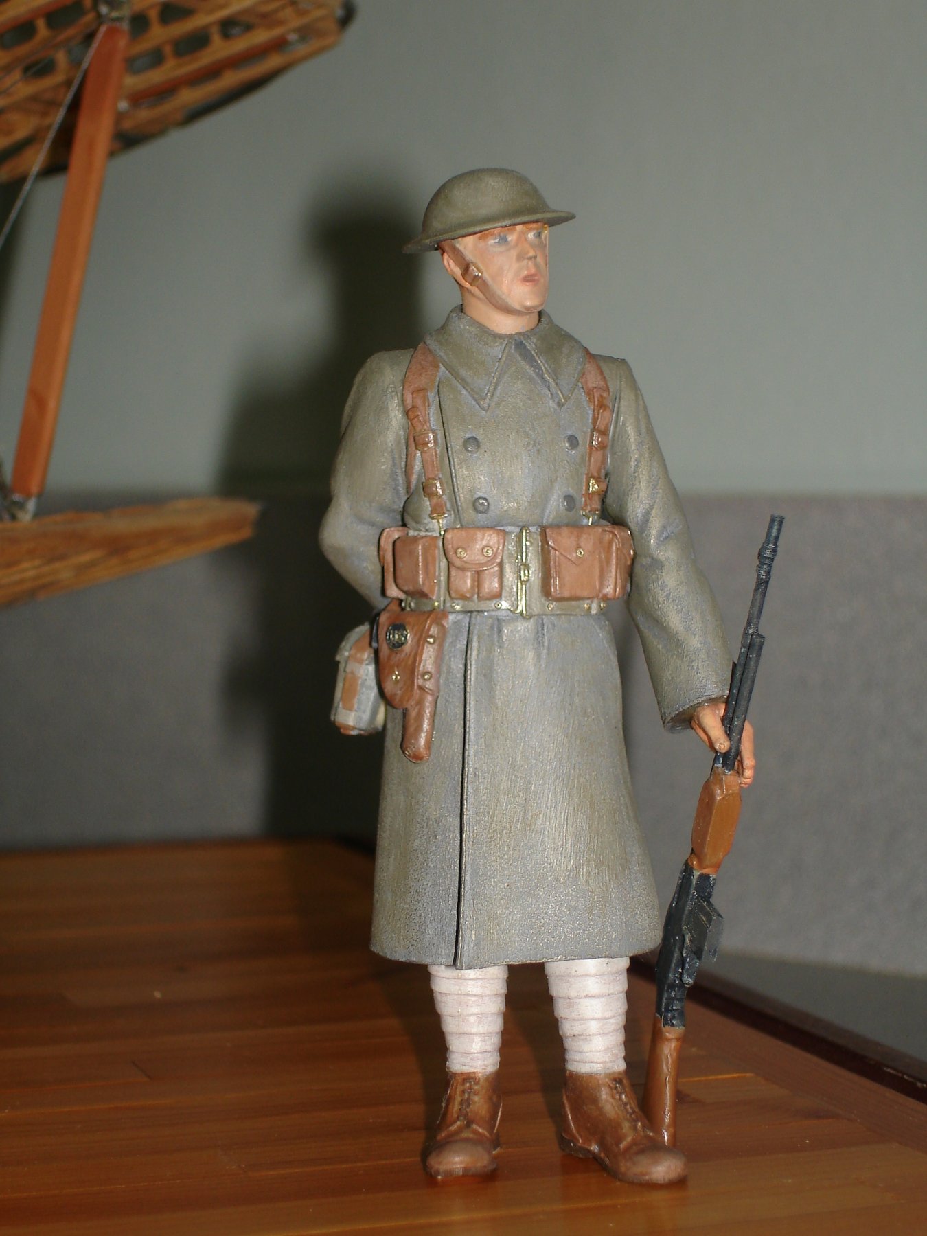
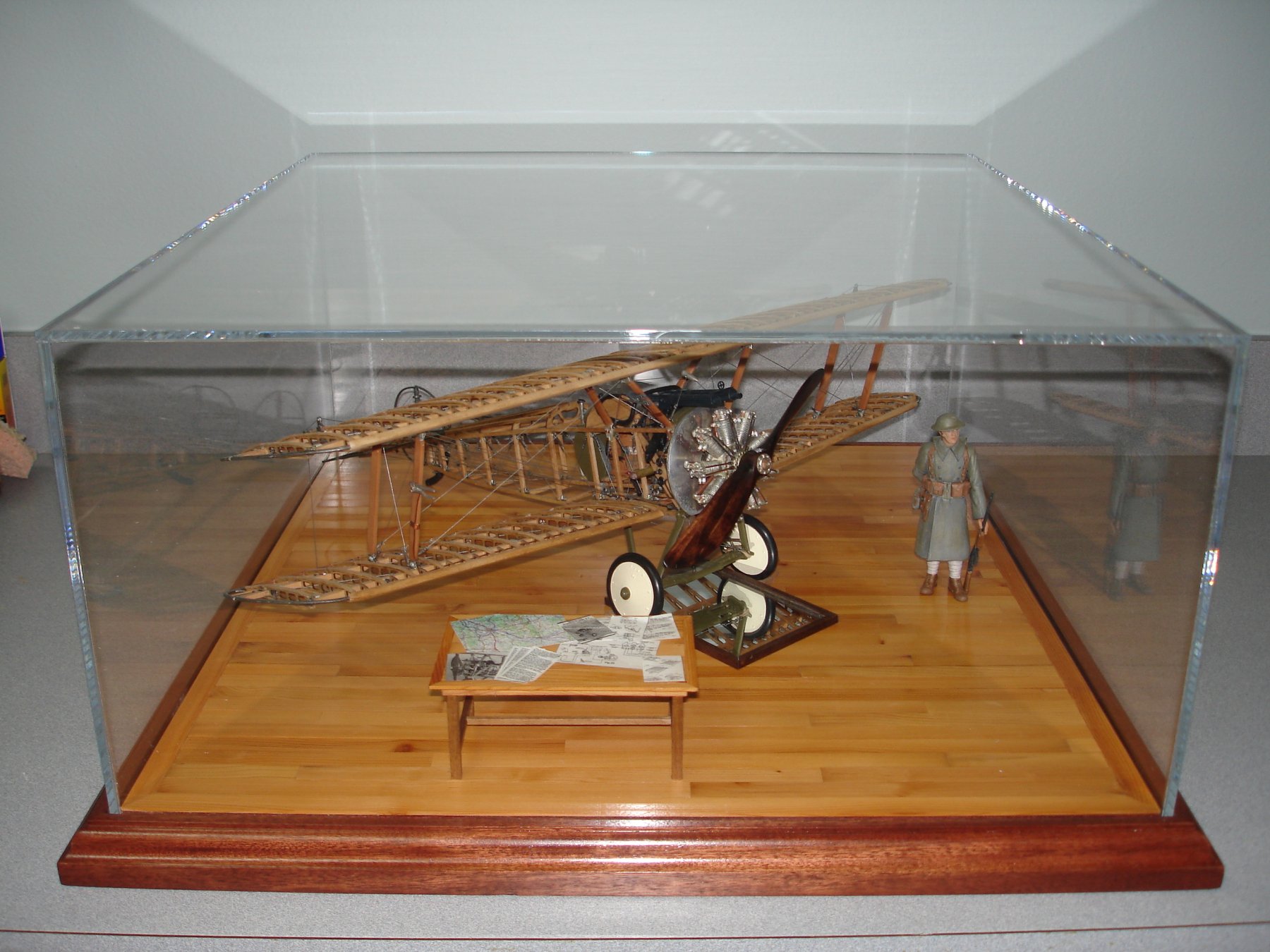
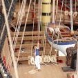
Nice work on the Sopwith. I built this model a few years back as a break from ships and like you, wanted to put a scale figure in the display. I can't really carve, so when looking on line all I came up with at anything close to the correct scale was a WW1 US soldier. If you search for this "verlinden 120mm WW1 soldier" you will find some available on eBay. Here's a few pics to show what I did with it. I think it is an acceptable alternative to a pilot and gives a good sense of the airplane's size. Jeff


- 114 replies
-
- 11
-


.JPG.ed1785de0c9c1b82e8bd79ba4d01fa14.JPG)
.JPG.fcdddbdcbc98eceaf691d2cfd0e053b9.JPG)
.JPG.2bb930088c52439451cc56da2705d77b.JPG)
.JPG.9428691bcdfb1d31650a9807b044803e.JPG)
.JPG.d138c877d0b50d88723c153e3d02422d.JPG)
.JPG.a2b700ff411b5844870d54704111f46b.JPG)

.JPG.fa8449431cb754c7131e12dd788510e8.JPG)

.JPG.11c53cfbee7129da7fccdae2d505854b.JPG)
.JPG.11cccb440579f6b7f43efce3f8d6ee87.JPG)
.JPG.e1e83ed7bc3d876939fd90f7348b42b7.JPG)
.JPG.5a6b9d4481db55c9992be19e3b0bba73.JPG)
.JPG.751ea384d94c7d3906cf0ab1c735f530.JPG)


.JPG.0f93cd43bc5cb4d89495ad6df7f82e1f.JPG)
.JPG.4c84eedf72d227efc402f40110dcaf1a.JPG)
.JPG.3eae6106dc10b07ed610223df42a0c46.JPG)
.JPG.91dbb0236231ea31a86bc700113ef06c.JPG)
.JPG.fec286ad2fab13f33c6a07238cd04dcb.JPG)
.JPG.f610d2c44f12857a7f4f819a0dfb1bb8.JPG)
.JPG.112241a6547753f6e03c3eabe98ce79a.JPG)
.JPG.54c4db5adb0194a0ad904118d52842b8.JPG)
.JPG.fa7f361f5aad49f8ec090a36e15781fe.JPG)
.JPG.0af21720079734dee218d08648aaafc9.JPG)
.JPG.6c30c6da2e23f122bbea6934f5a8b25b.JPG)
.JPG.fb7eeb0eea5b483a9610bdf1d333048d.JPG)
.JPG.0b7231bfe3389d3cb7223ddcf2b2c03f.JPG)
.JPG.487b7da78feb9865252818f1c8c4e918.JPG)
.JPG.09318c34cdc1e10fb88fa8bd571fa899.JPG)
.JPG.32d4a946bb4c4db7bf06f92e64050f13.JPG)
.JPG.8ecb4671c867d233aa00eb6bfd74e5d4.JPG)
.JPG.a3f90add7ee946baa6a45cf1d13615a6.JPG)
.JPG.4e707ebed6a2b44e18d2db30718375c7.JPG)
.jpg.9715970bddb62475aa97e85215945f6b.jpg)
.JPG.dc527c96a72b747b8f22ad64770c6c26.JPG)
.JPG.f392fb08fe94e5ef7585be8c5d0849e1.JPG)
.JPG.198f6ed2c3b6bae79d5a0bbd277568c9.JPG)
.JPG.a5ba055fcf0a2cd8f94b7076e02e1264.JPG)
.JPG.1c671a5f01680c753cf93722ac8b6df6.JPG)
.JPG.a1d488adf8243ba15e568cc2eaacf5b6.JPG)
.JPG.7cead94ca57f7a54e1a7f1a6276abdb2.JPG)
.JPG.742c6b1be93dce51a55788564734c349.JPG)
.JPG.6dbb8fc32b745c620fca435fe8f95df6.JPG)
.JPG.61a9567ead8ac7f29d0c94e001391ac6.JPG)
.JPG.c80f666e5437765ef118a968646ab6c3.JPG)
.JPG.46f86807fbbfdbc2700db33945177085.JPG)
.JPG.c0f4ae396cdebdf5f9309901c14fc9fa.JPG)
.JPG.7e54558e6893d2cbc61edaaaf5d0a0dd.JPG)
.JPG.41150f0eaab5db835ed99be6b530c020.JPG)
.JPG.8a3081612389ceff4a11682cb10cd2b8.JPG)
.JPG.0db9a61d0f950fc3ca06e1a81a49e89b.JPG)
.JPG.1207c42e5f2fdf1fc994dac0b6289fb8.JPG)
.JPG.fdaa4e6575e7a0518259c340ec18c67b.JPG)
.JPG.872acfe1861aeecc2c69ac7a2f928cb8.JPG)
.JPG.70b099b11a0b0771affe335d5358e85d.JPG)

.JPG.47afcdccb637000a4b7324e5b2198c93.JPG)
.JPG.8482a49d5985a09677b0c1f55b9abfea.JPG)
.JPG.a51a8e65f4ec58fb76c117af0a44a1dd.JPG)