HOLIDAY DONATION DRIVE - SUPPORT MSW - DO YOUR PART TO KEEP THIS GREAT FORUM GOING! (Only 13 donations so far - C'mon guys!)
×
xodar461
-
Posts
172 -
Joined
-
Last visited
Content Type
Profiles
Forums
Gallery
Events
Everything posted by xodar461
-
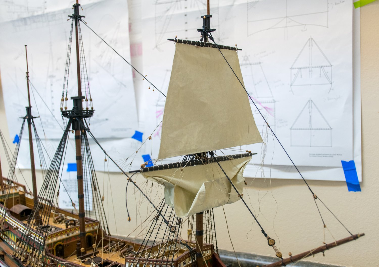
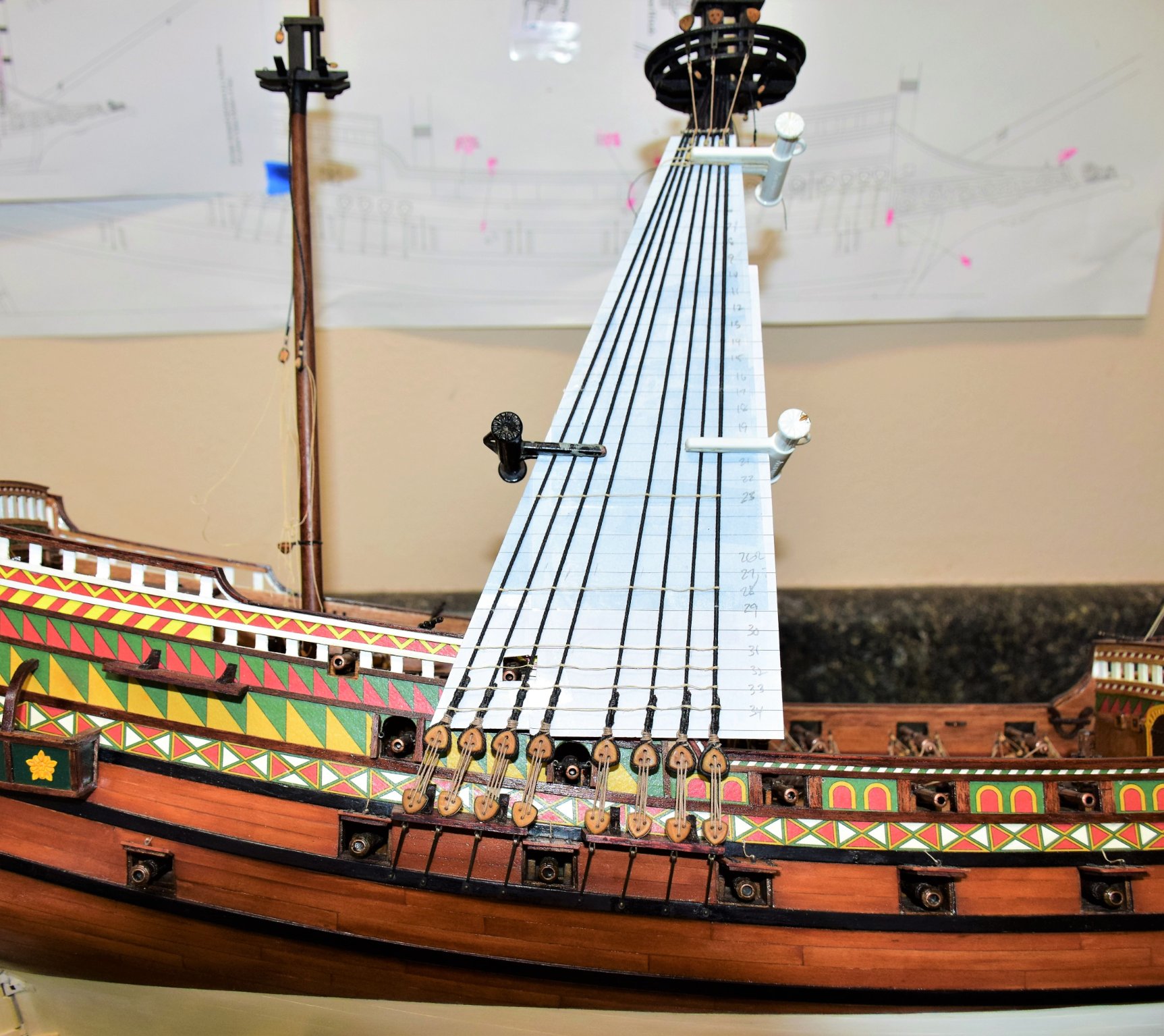
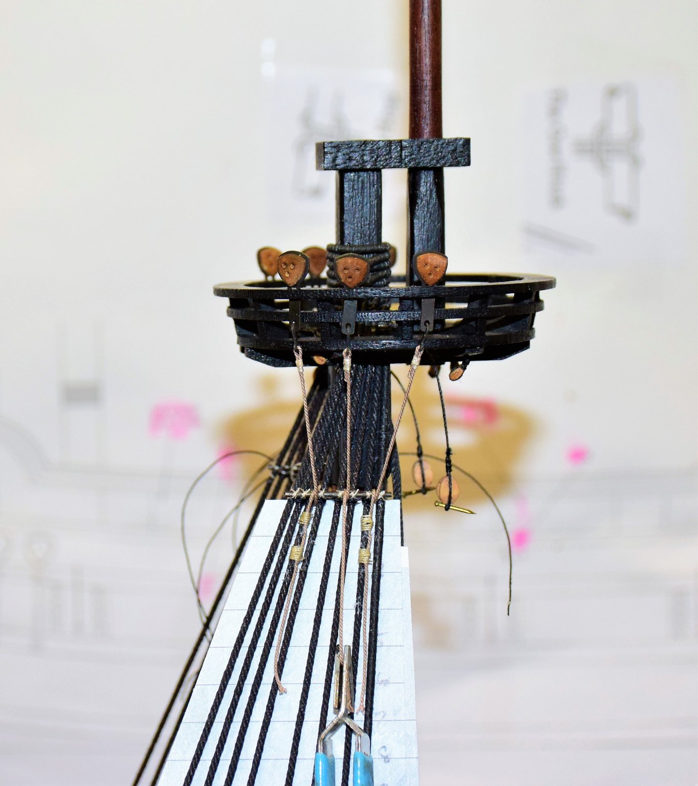
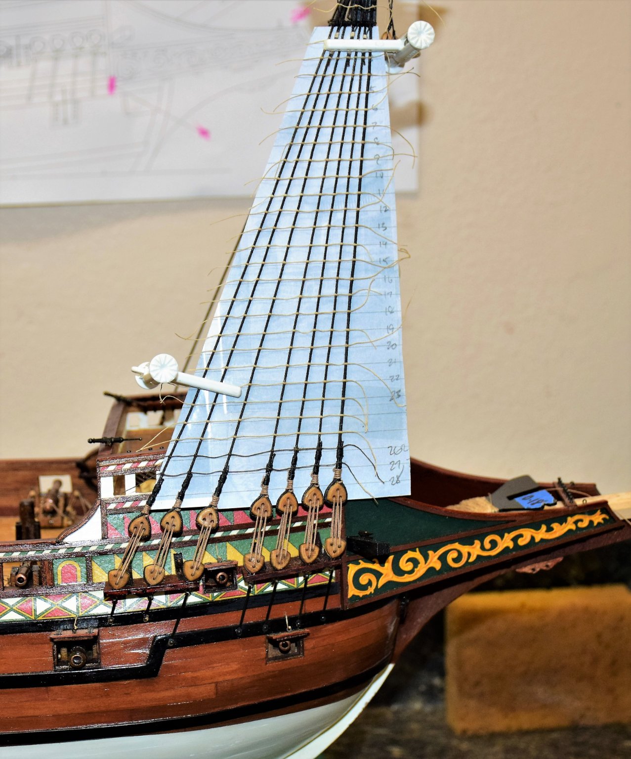
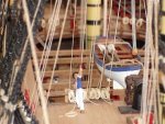
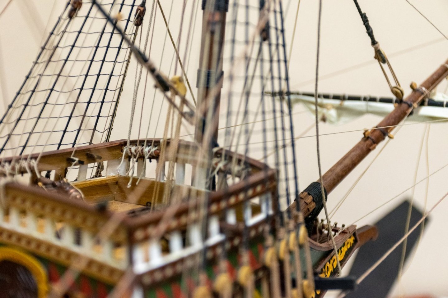
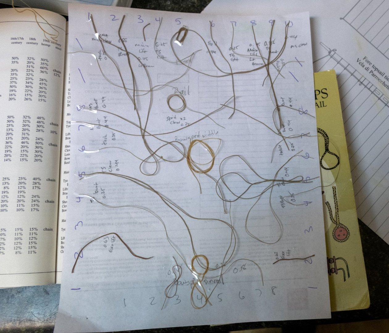
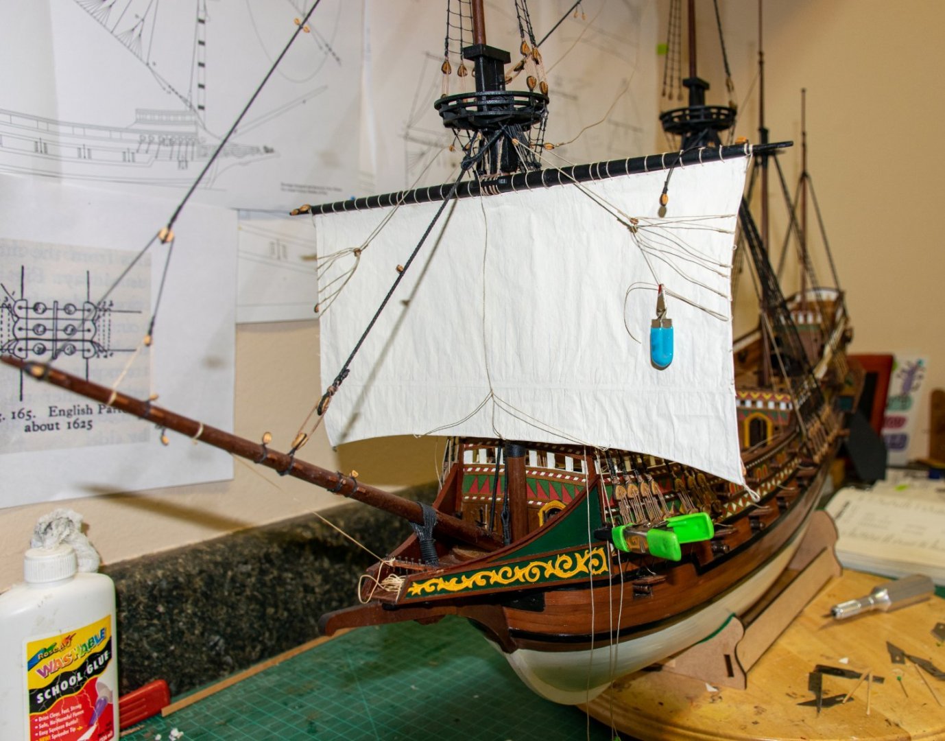
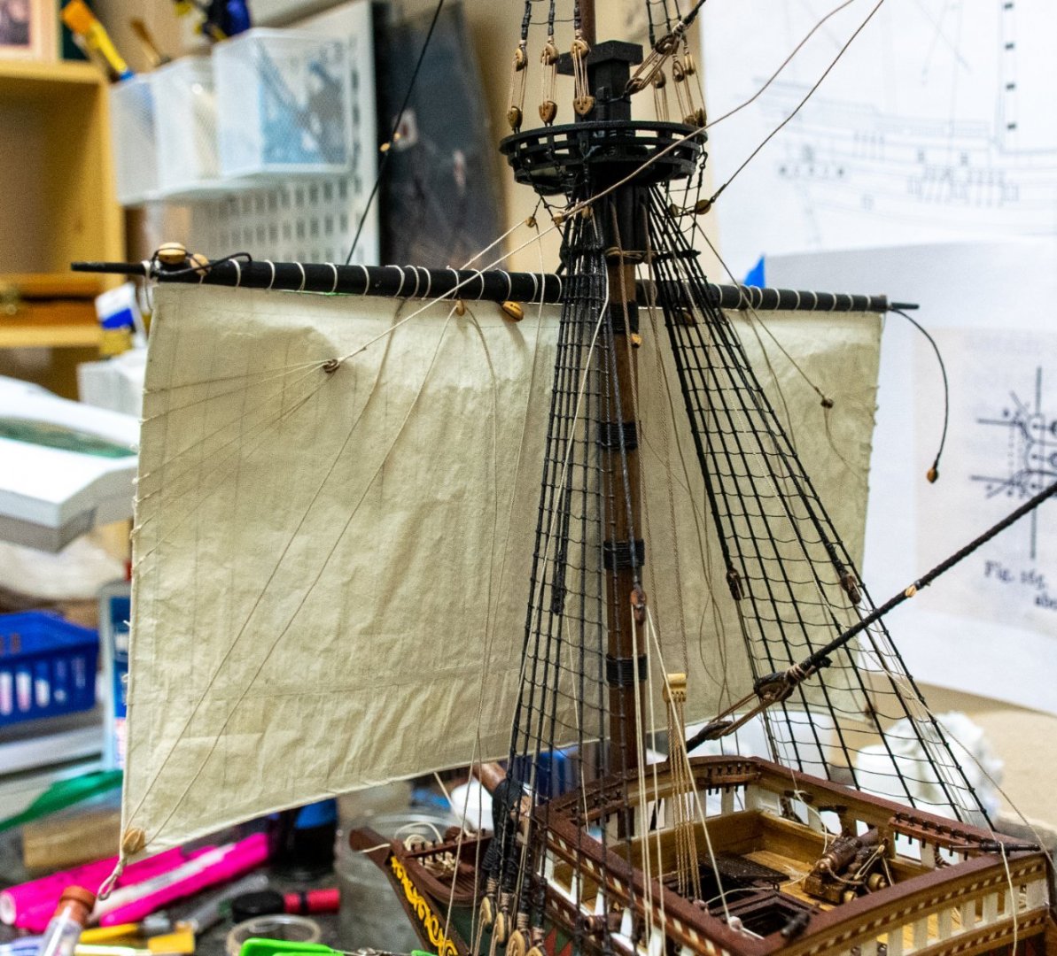
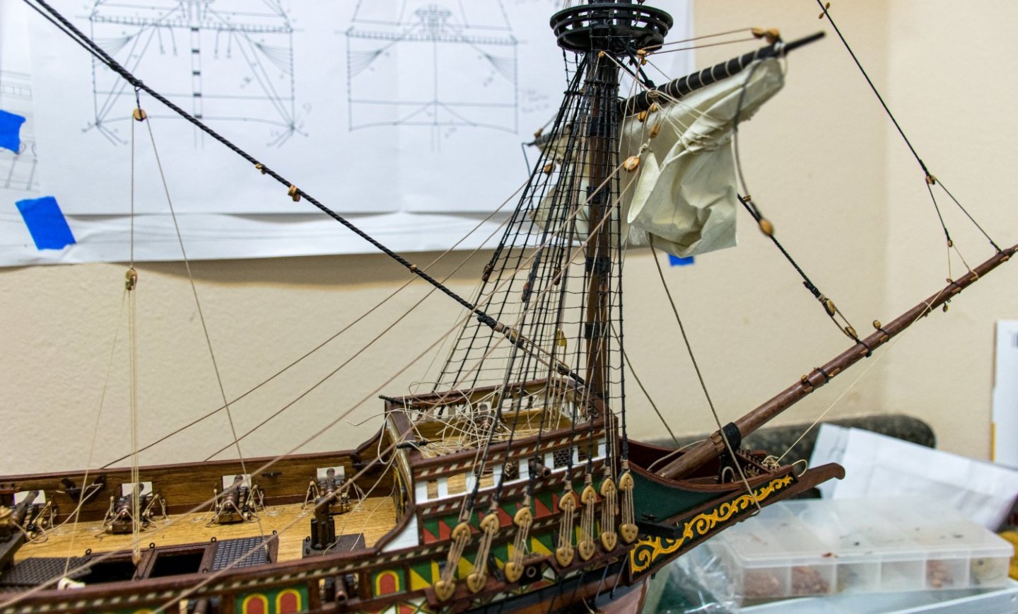
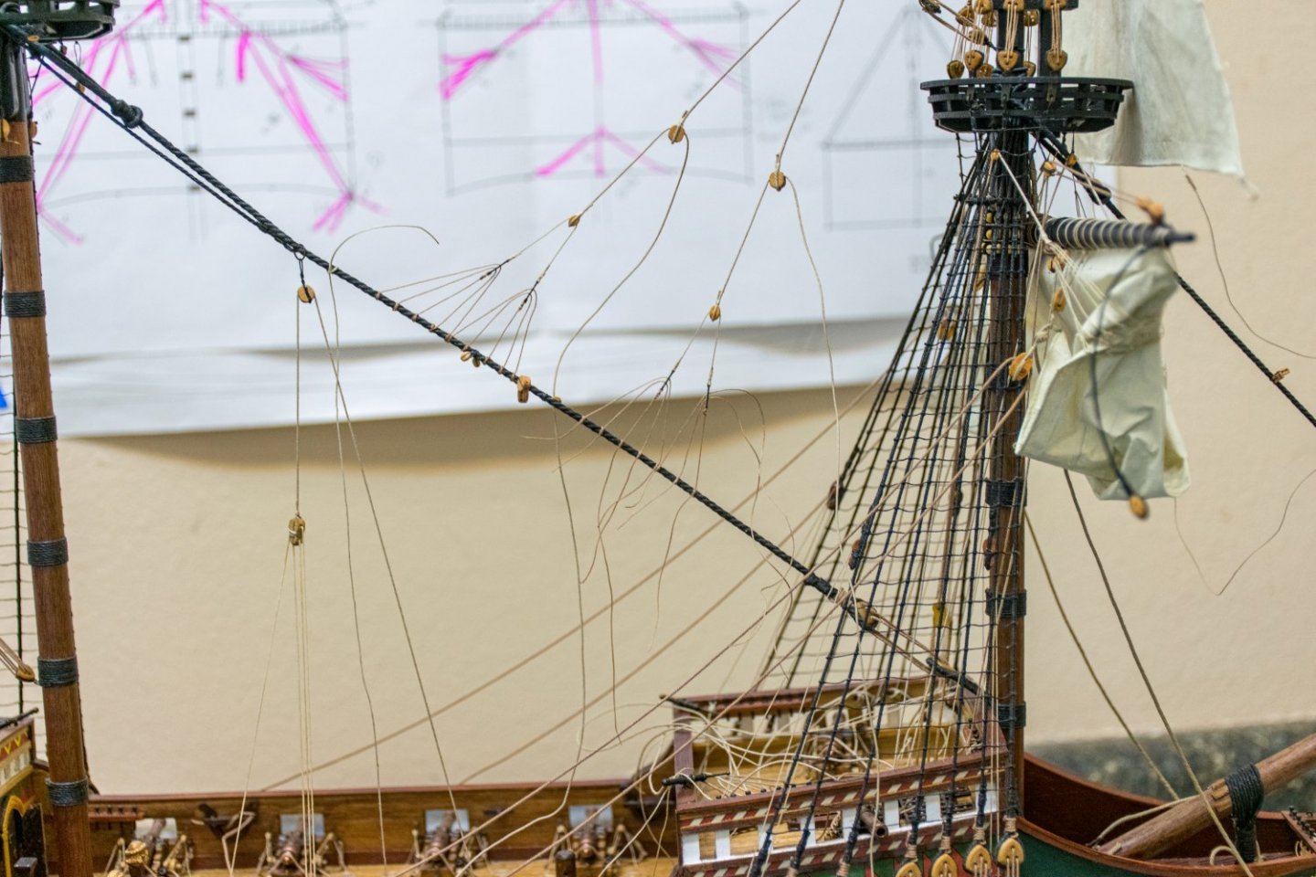
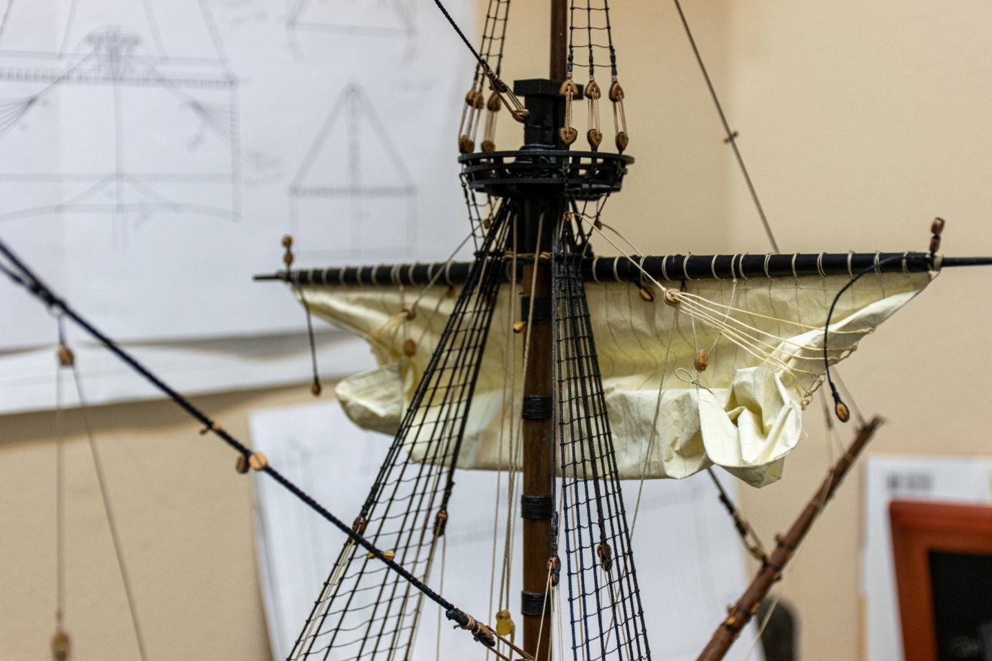
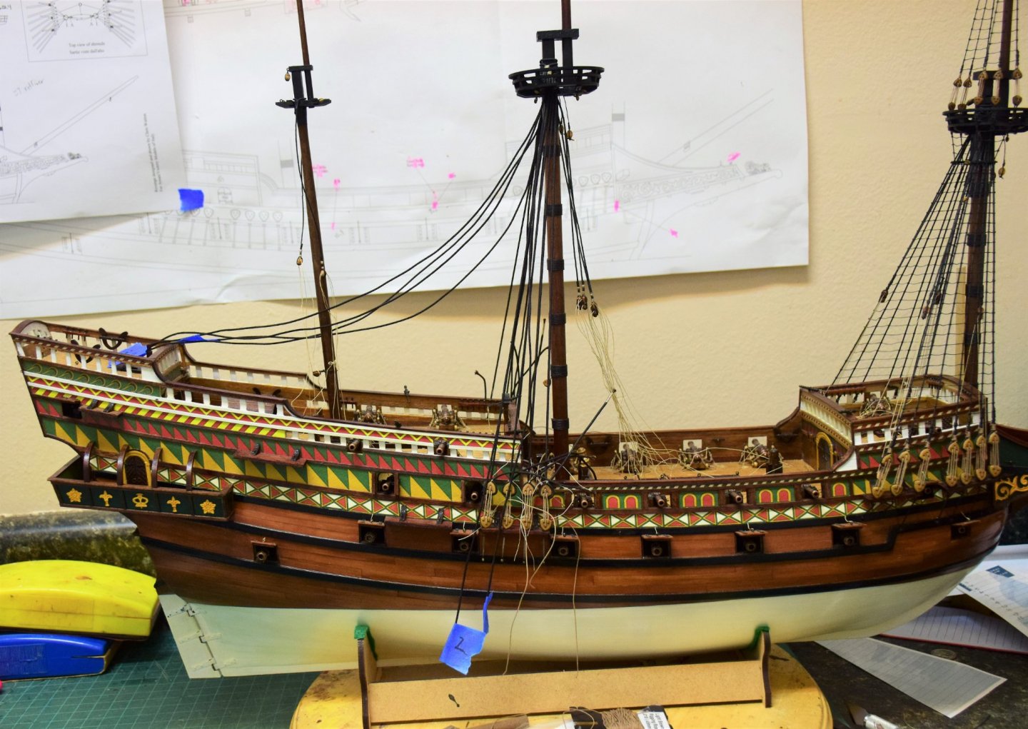
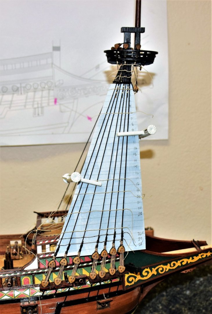
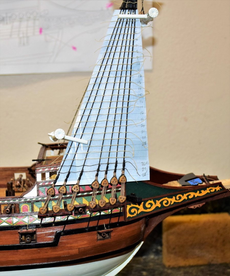
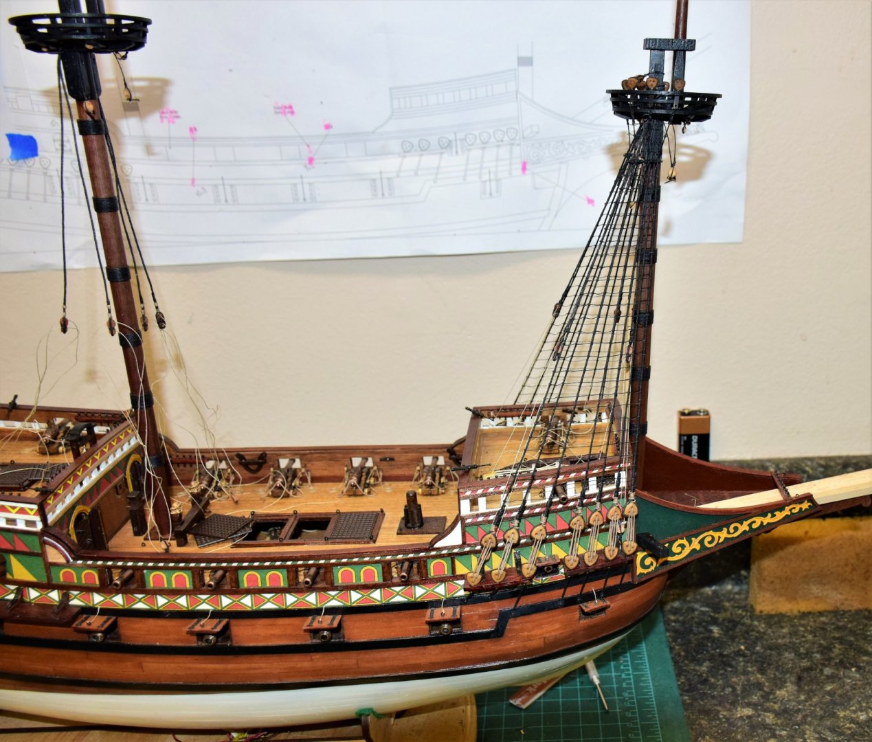
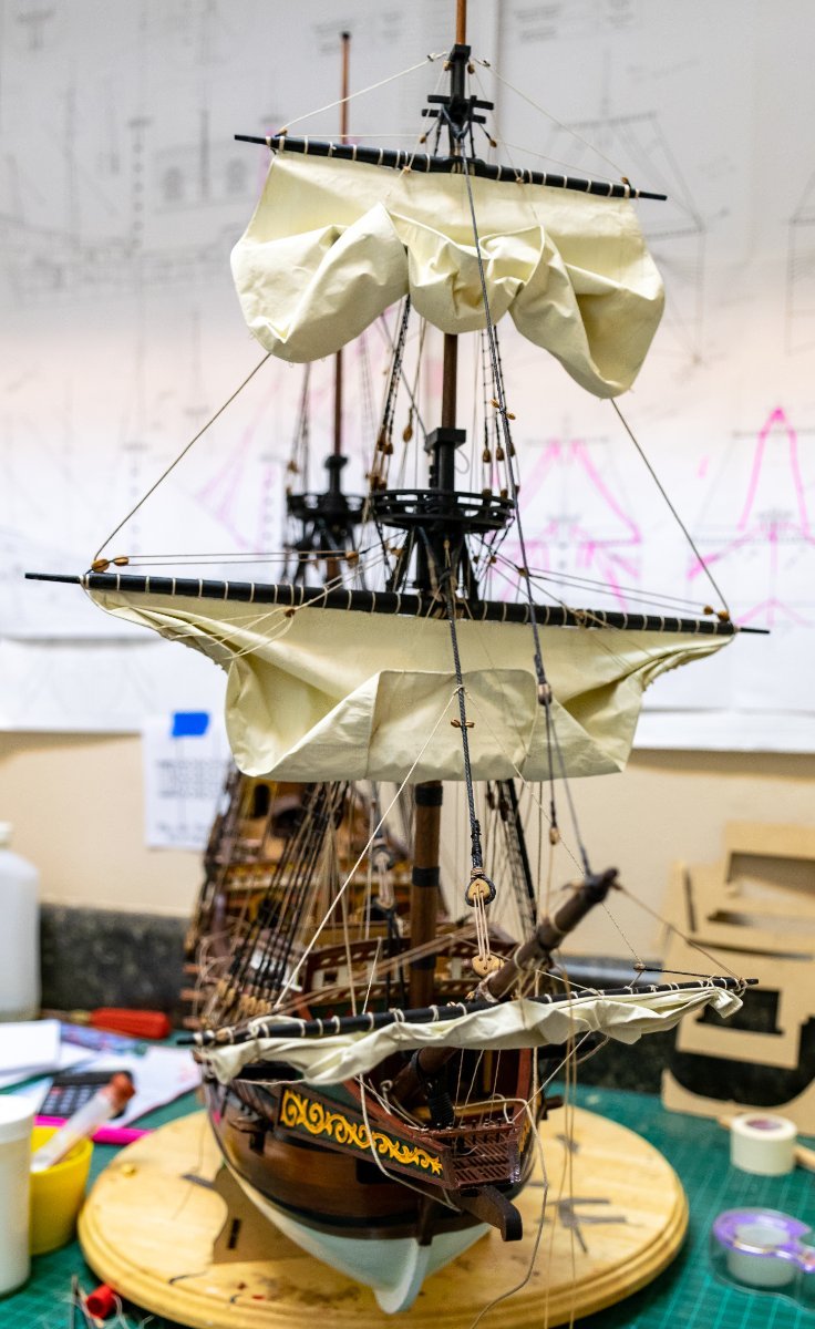
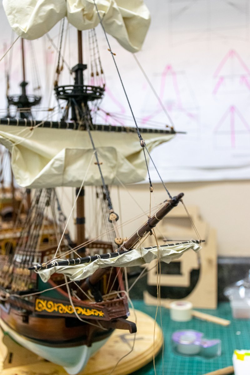
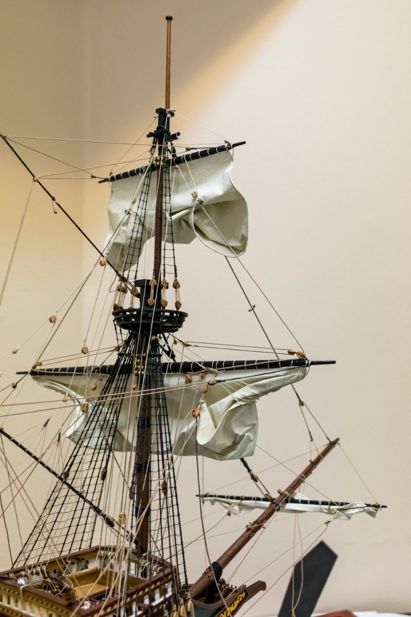
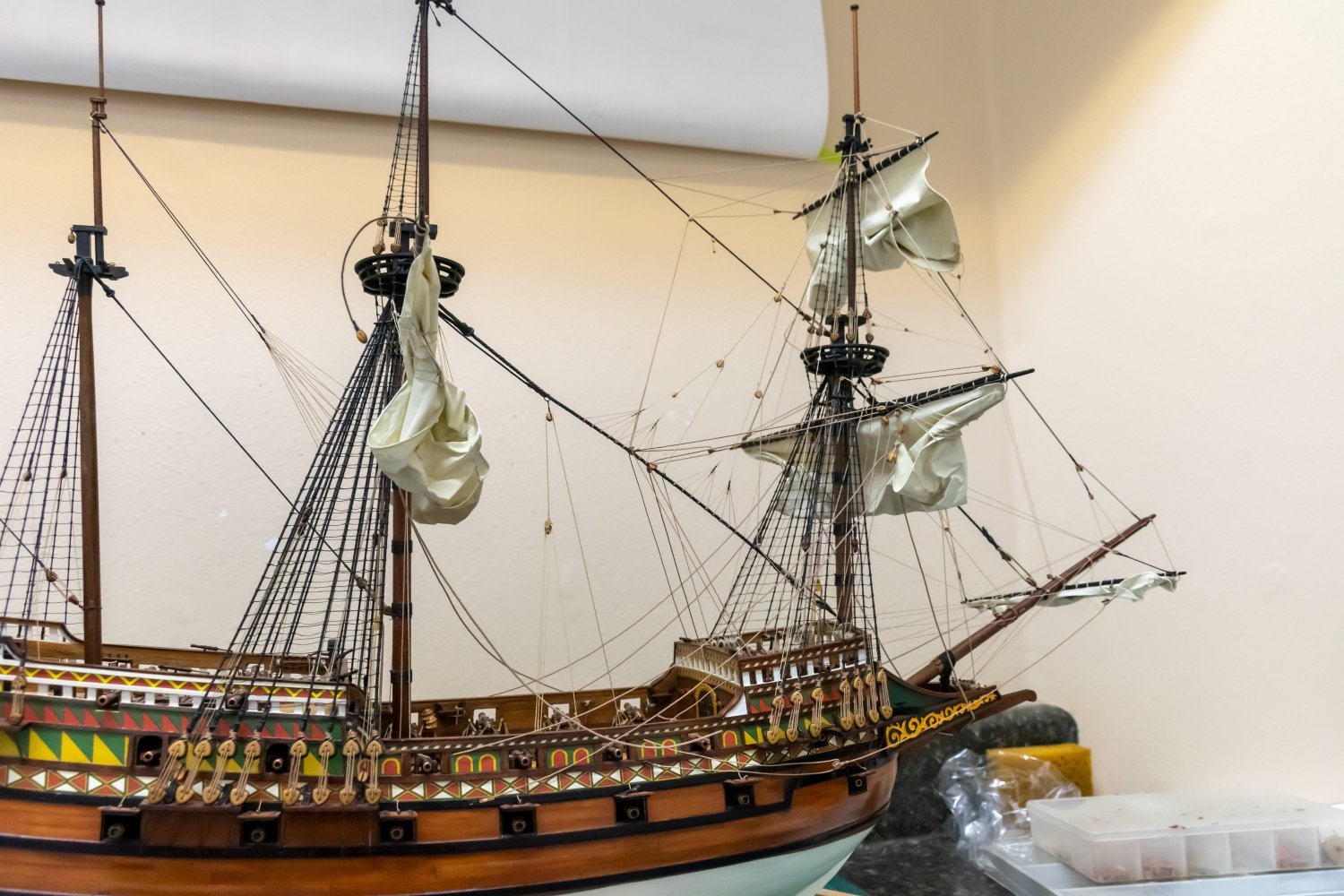
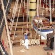 Greetings Work continue on the sails. The sprit sail, fore course and topsail lines have been placed except for the bowlines in the following photos. The spritsail is shown partly furled. Here's a photo of some of the lines belayed. In order to remember the size of each line and where it was rigged (in order to make the appropriate coils), I made this cheat sheet to represent each belay point on the fore deck. The name of the line and rope size is listed for each belay point. After the main course was set, I decided to finish the lines to the sprit sail and the fore sails. This included the sprit sail sheet and the fore sail sheet and tack line. Some completed rope coils... forward view of work so far... And finally one of the crew working the sprit sail halyard. Jeff
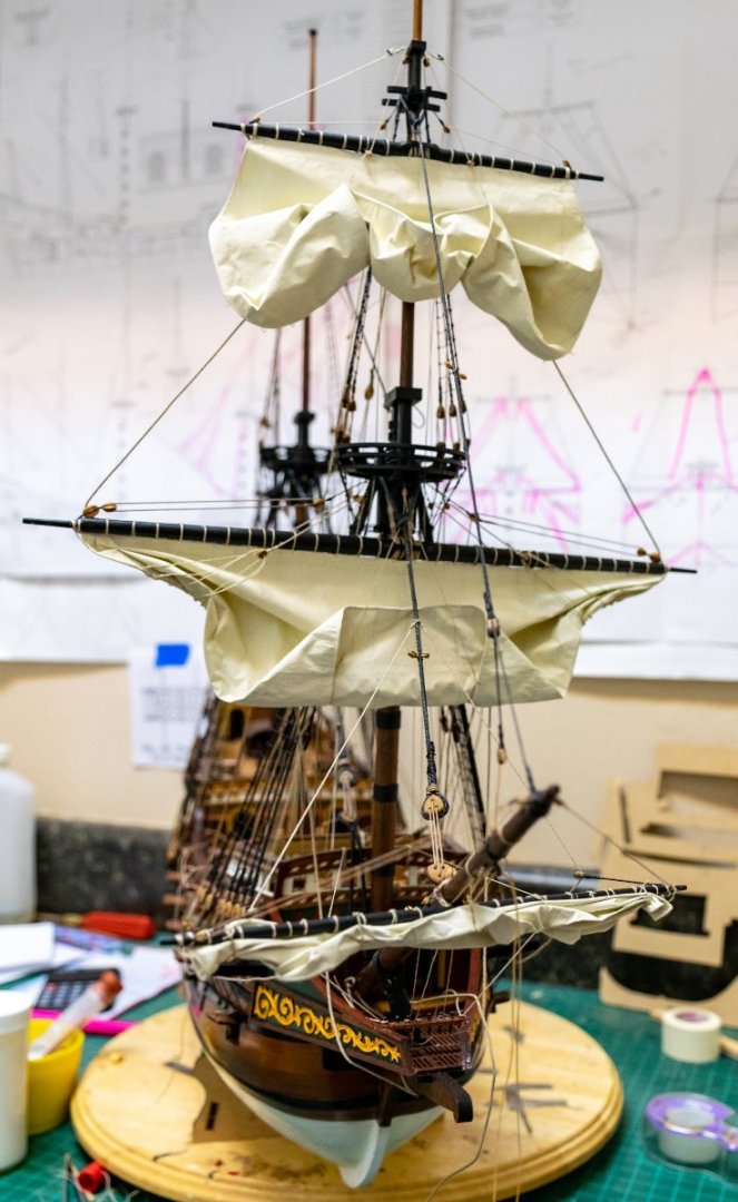


.thumb.jpg.d5266cfbd547951f54186f26f1b2b296.jpg)
.thumb.jpg.04a6b2241981ba65c6949a0c8d4533ba.jpg)
.thumb.jpg.bed12283025921693a3acd533432dbc3.jpg)
- 159 replies
-
- 11
-

-
Very nice work on the planking. I'll enjoy following along as I am currently building the same ship Jeff
-
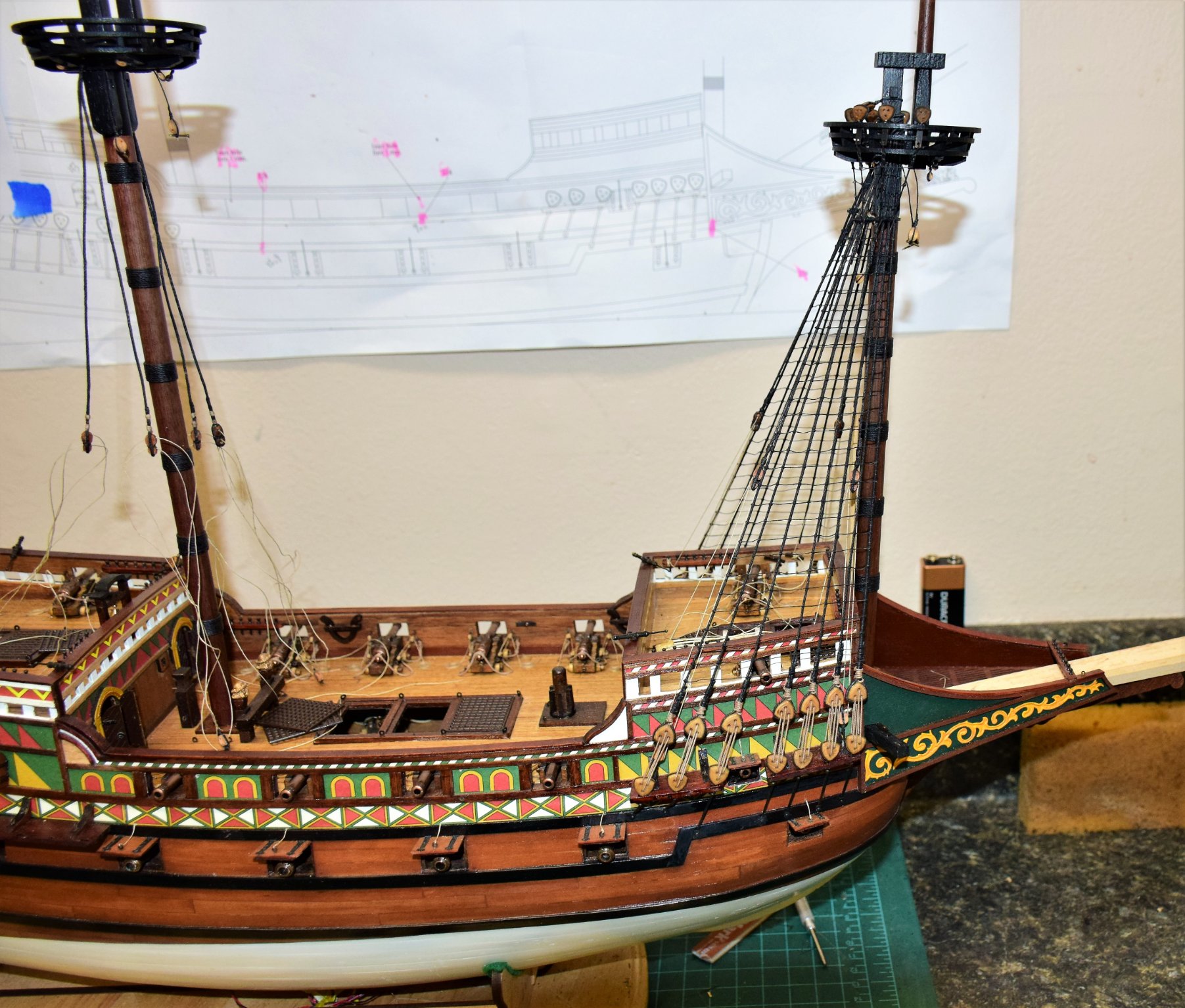
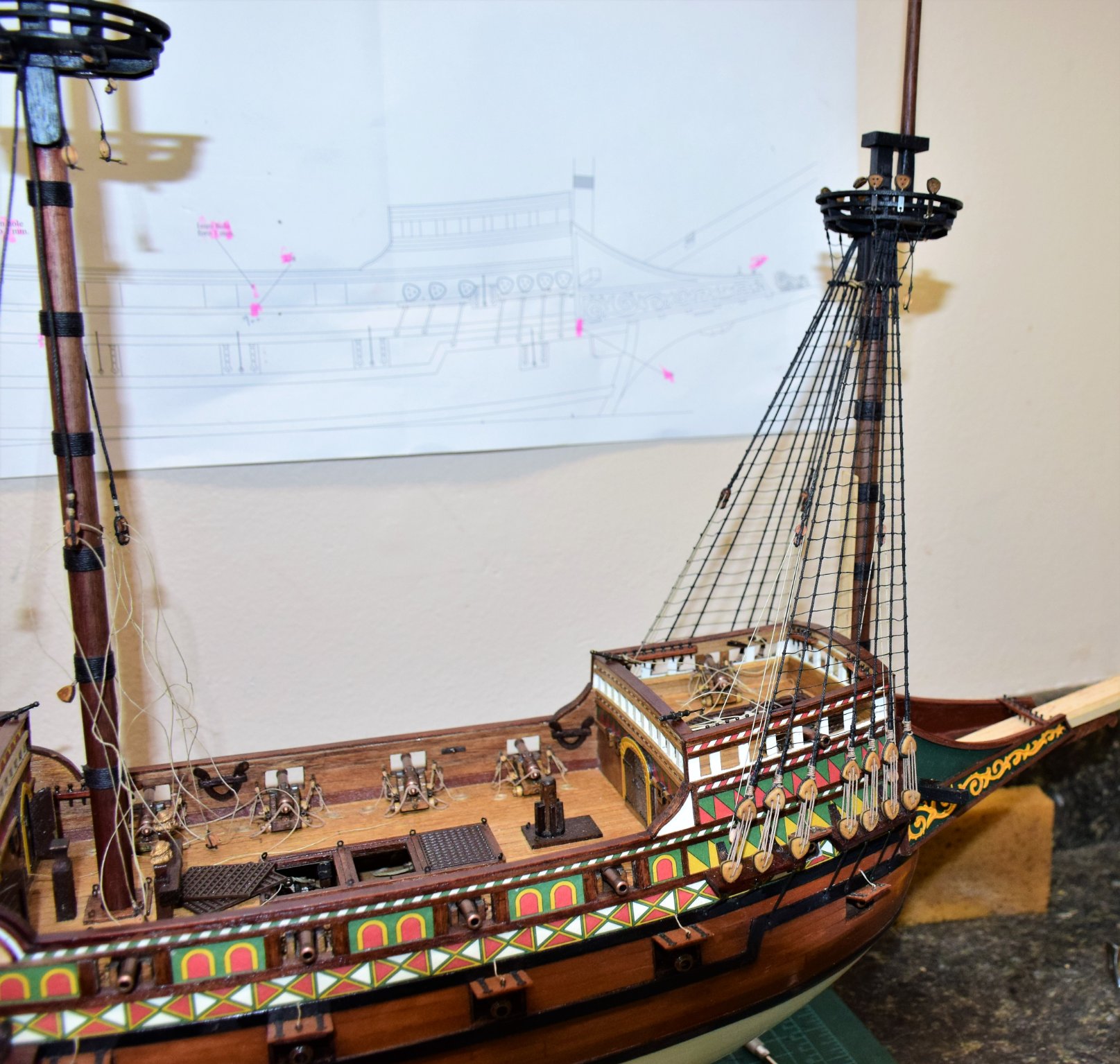
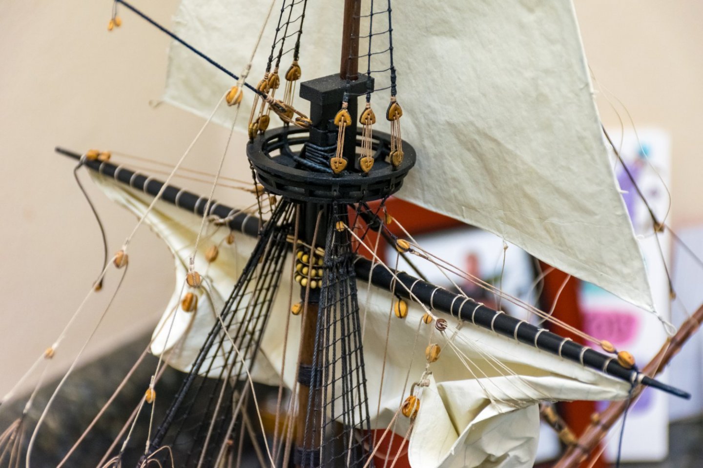
Greetings! Construction continues...below - martnets and buntline on the forward side of the fore course. The Halyard was a bit of work to place as the lanyard and block were placed a long time ago as the knighthead is below deck and unavailable to rig. The first loop around the yard was easy enough...the second one had to be secured with the mast in place and under the correct amount of tension. Not visible is the 1mm brass rod the was placed to hold the yard onto the mast. This also keeps other lines from pulling the yard up. At full scale the yard would have enough weight that this would not happen but at this scale, there is not enough weight to pull the halyard down naturally. On the aft side we have the martnets and the clew lines. Fore course sheets and tacks now attached to the fore course clew. The sheet lines had to be taken down a bit in order to have access to the fore deck for placement of later lines. These ropes were used to pull up the sail to its current position. The sail is lightly sprayed with water making is quite pliable and easy to draw up. It will then dry and keep its shape. It was at this point that I realized I forgot to place the parrel trucks and beads (see photo 2 above). The work was a bit tight however I was able to get them on as can be sen below. The fore yard lifts are also on at this point. Here's a view from the front. Only line left is the bowline which will go on after the topsail and sprit sail are on. Next up, the for topsail. Placing the halyard and lanyards for this is quite the process. Everything has to be checked and rechecked to get the correct tension without pulling the main stay way out of alignment. here's a photo on the work in progress... And finally the topsail ready to rig. One of the issues with sail placement is finding a place to belay all of these lines. Some of the belay points on the plans did not seem to work and in some cases up to 3 lines were to be belayed at the same pin. I was able to make it work with a combination of the belaying pins and the rails and modification of the run of some of the lines (belaying pins may be an anachronism for this period but so be it - leaving them off and tying all of these ropes to the rails is not something I wanted to do). Most of the work on the topsail and sprit sail is complete and I will update with more photos soon Jeff

-
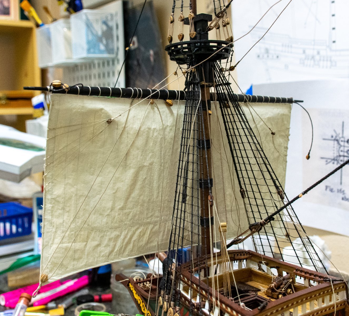
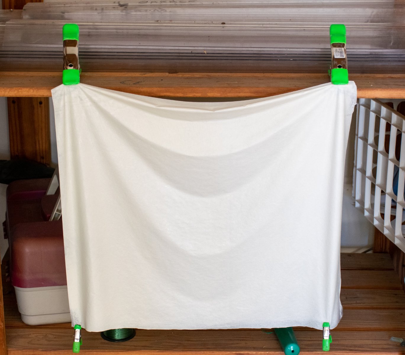
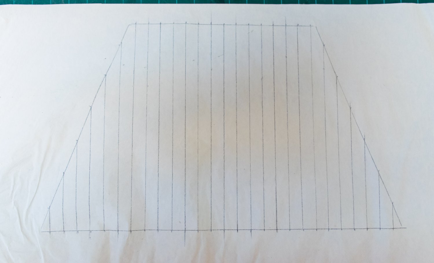
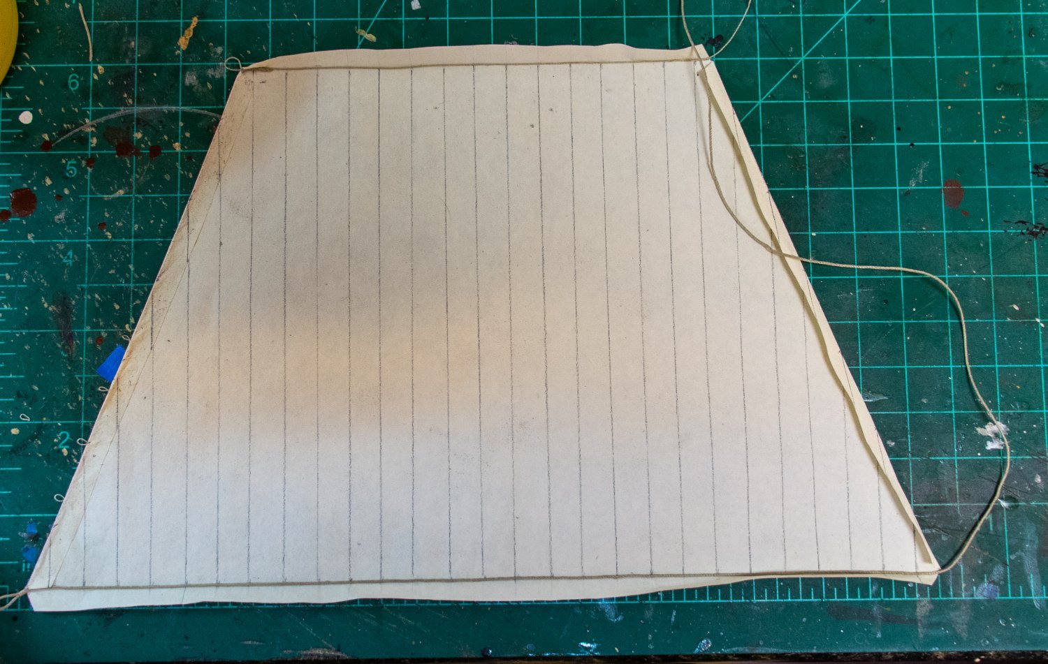
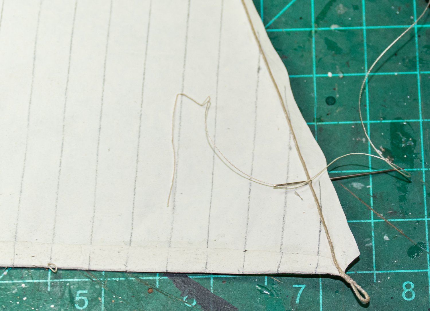
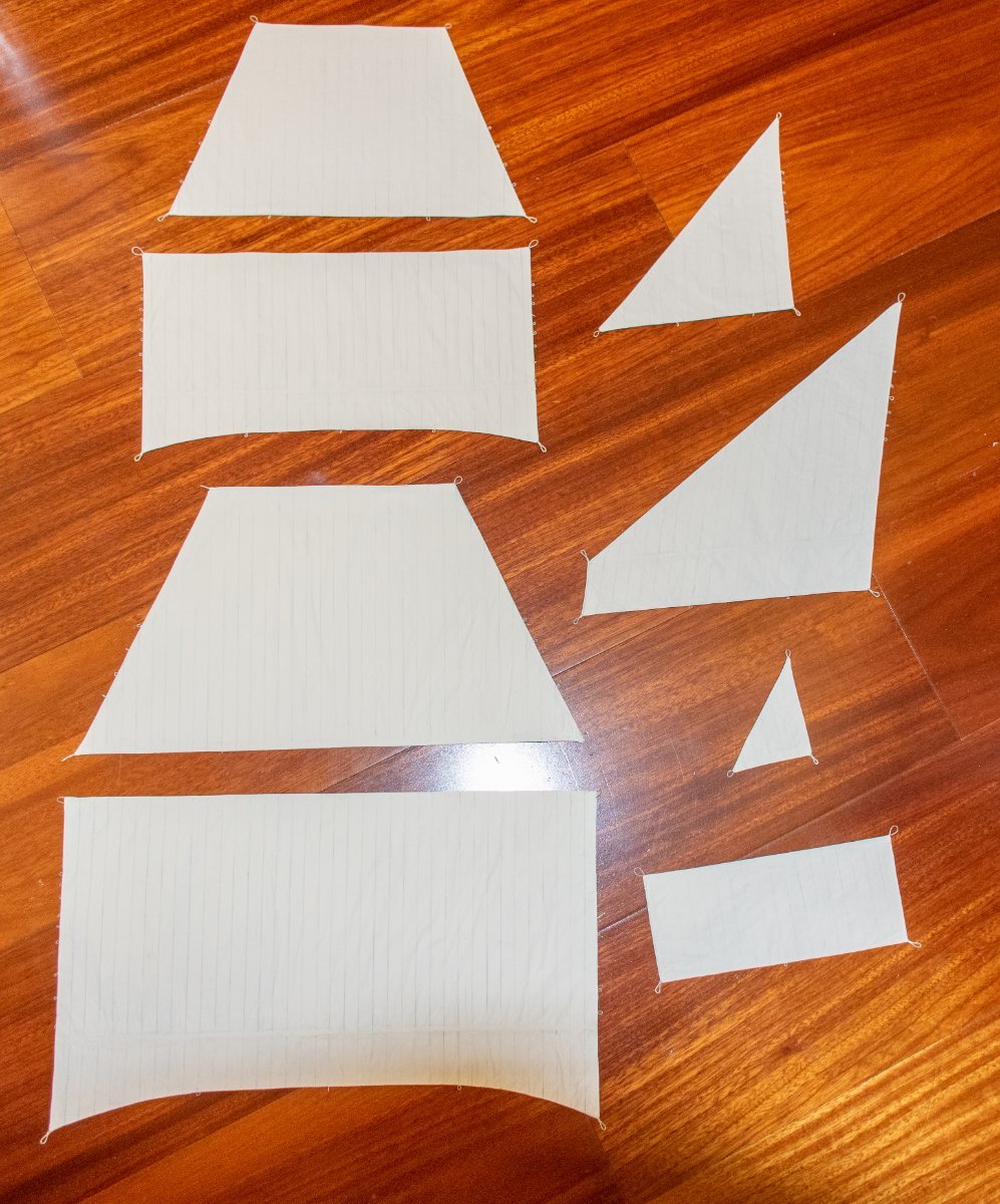
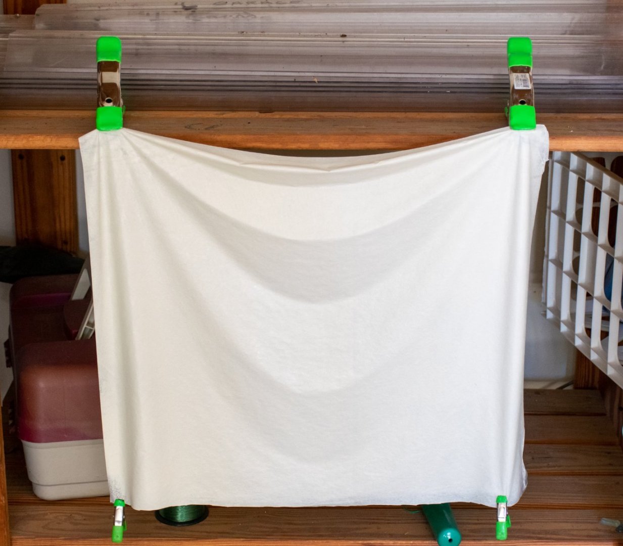
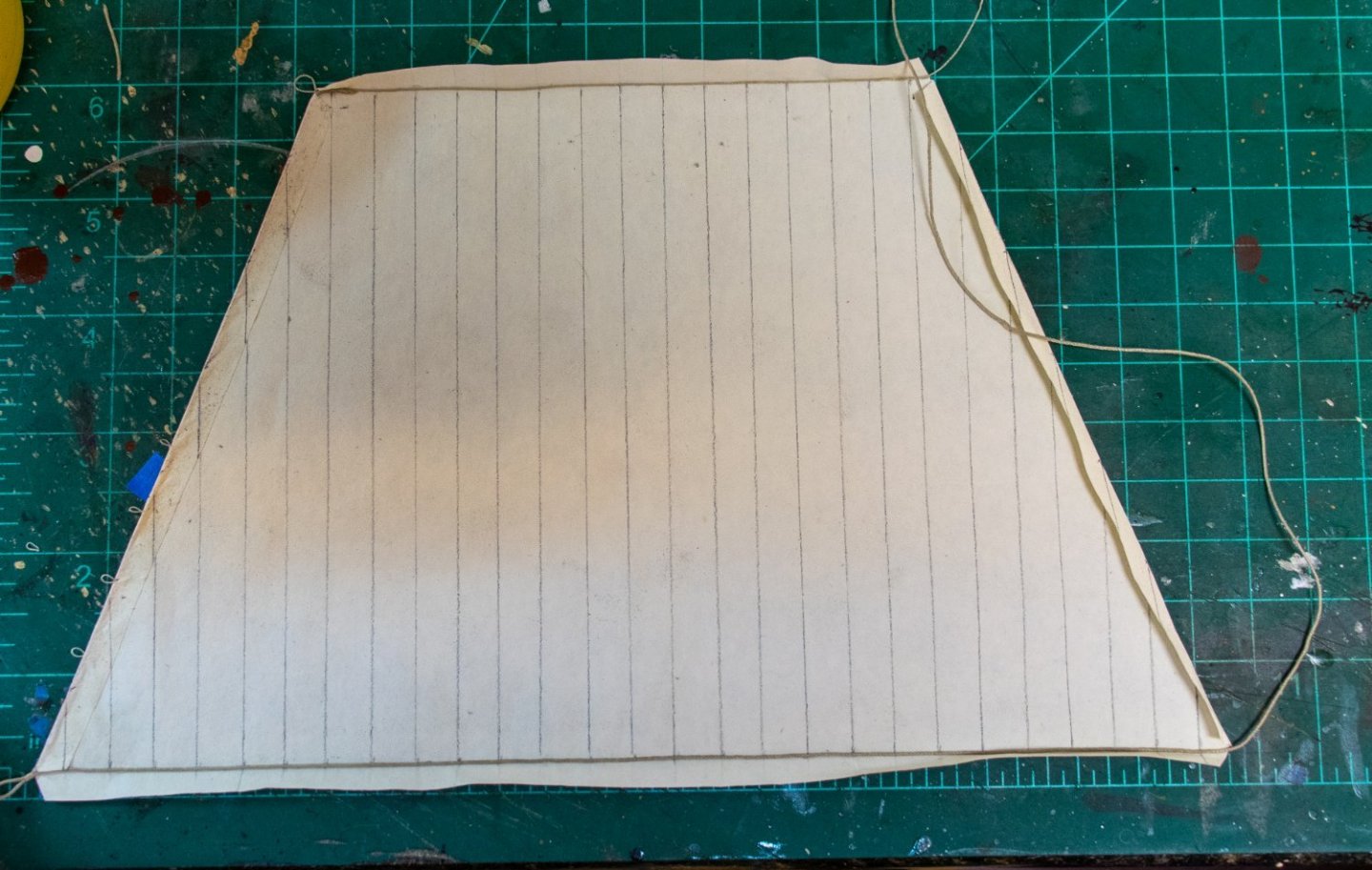
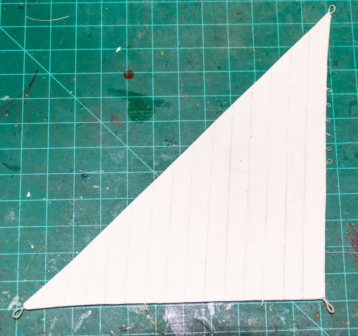
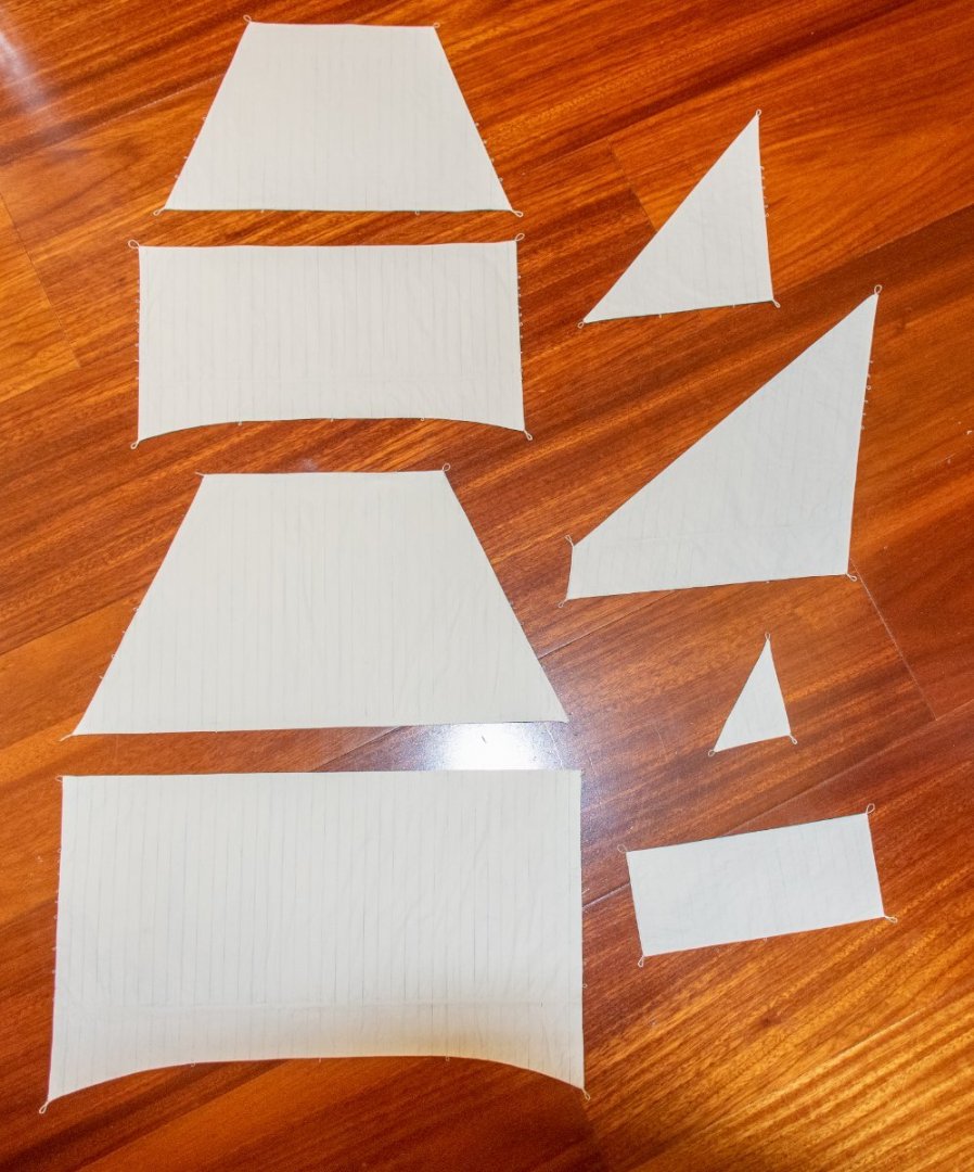
Greetings! For anyone interested, here is a brief description of how I made the sails. Comments and posts regarding sails and their construction on MSW were quite helpful as I have never done this before. Starting with a sheet of silkspan, one side was painted with a foam roller and hung to dry (I used some acrylic paint, cream color, that had been used for walls in the house). The kit provides templates for all the sail. These were cut out and glued to cardboard to provide some thickness. The sail outline was then traced onto the silkspan. Seams were marked and drawn onto the sail with the result below. The sail was then cut out with ~5mm overlap that would be folded over to secure the top and bolt ropes. I know this is not how the ropes were attached however at 1:64 scale there is no practical way to sew the rope to the silkspan so I figured this compromise would work. Photo below shows the process with the head rope glued and work on the bolt rope. The flap has been folded over and glued on the left. The bolt rope was one continuous rope from the left upper corner to the right. The clews were easy to make by just leaving a little extra and seizing the rope. The cringles were made by passing a needle with a small thread through the bolt rope at the appropriate intervals (as marked on the sail plan). They are pretty secure once the flap in folded over. This process can be seen below. After the ropes are placed I lightly paint the sail to lessen the prominence of the seam lines (this also makes the foled over flap of silkspan less visible). On my previous post, I think the lines are too visible on the fore course so this extra layer of paint make them a bit fainter. I ended up redoing the this sail for this reason and also because I placed the robands at the seams and after further review, they should be midway between the seams. Photo below shows a close up of a lateen sail and then all the sails. Once the sails were complete I decided to revise the head cringle (or earring) as I did not like the loop as seen in the main topsail (second from bottom). It should look more like the main sail (bottom). I've already got the fore course, topsail and spritsail rigged so more photos to follow Jeff


-
Scale is 1:64 Thanks to all for the advice. May take Roger's advise and just skip it. Jeff
-
Greetings! I am looking for a ships boat to compliment my Revenge build. Does anyone have any recommendations for a commercially available ships boat kit that would be close enough for this period. I've seen what is available with Vanguard Models and Master Korabel but these are meant for ships of the 18th century and I think may not be appropriate for the 16th century. I might be able to modify a kit but I've not had much luck finding a picture of said boat. Thanks Jeff
-
Greetings Kirill Great points, as always. Every time I look at your galleon I am amazed with your work. On more than one occasion I have used it as reference for the Revenge. Re: the blocks at the end of the fore yard, they are indeed the same size as that was what the plans called for. After some thought, I decided to change them on both the fore and main yards to a 6mm block for the topsail sheet at a 4 mm one for the lift. I have some 7 mm blocks but I think visually they look too big. As far as darkening the lanyards the time for that has passed - I don't want to try to darken them up in place and it would be way to much work to redo them. As they are a medium shade of brown I do not think they detract from the overall look. I may use black for my next model (whatever that may be) but I do like the contrast even if it may not be historically correct. And finally, I think I will do as you suggest with the sails similar to the photo above. I will continue to post as things progress. Thanks as always Jeff
-
I am using silkspan for my current build of the Revenge. I got it from a company called SIG. it is offered in light, medium and heavy. Here is the link: https://sigmfg.com/products/sig-silkspan-tissue Here is a photo from my build log. I am trying to simulate sails partially drawn up as if the ship was at anchor but not completely furled like they might be if the ship was in port. Jeff
-
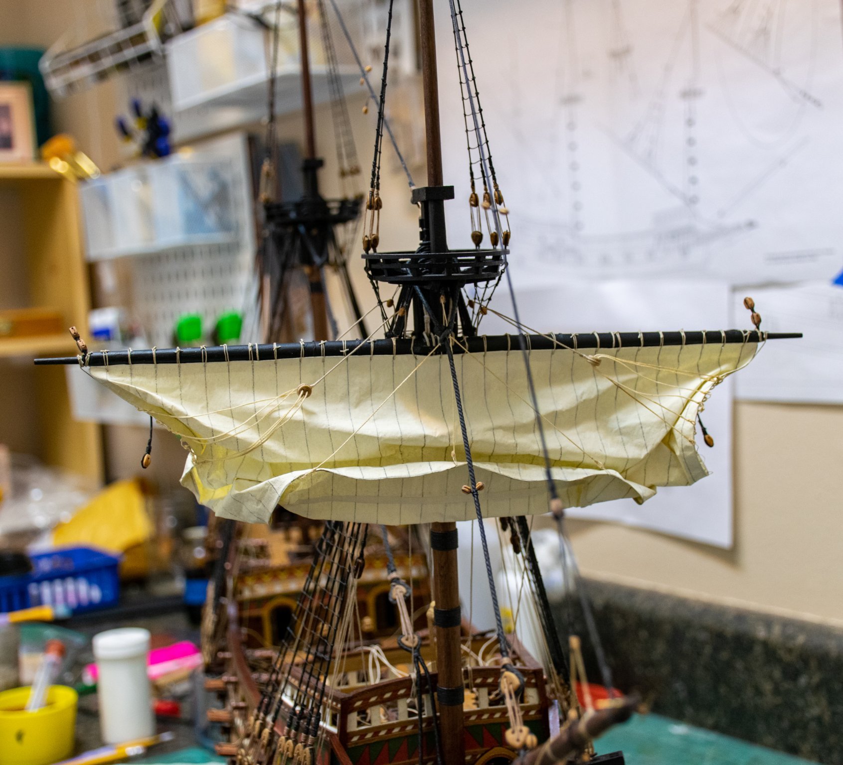
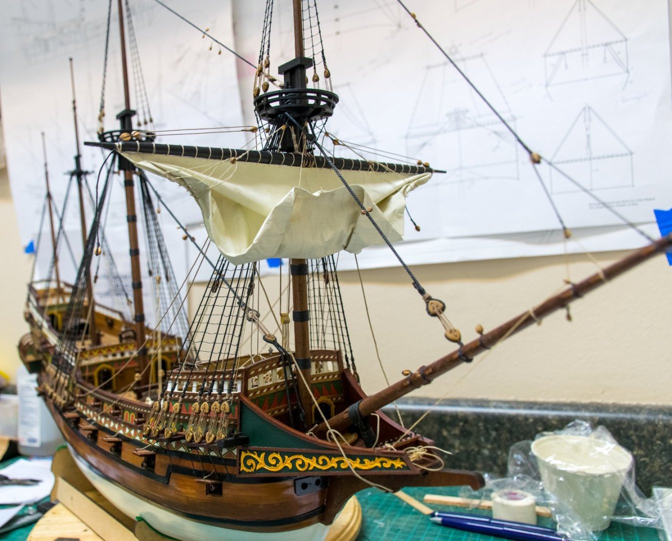
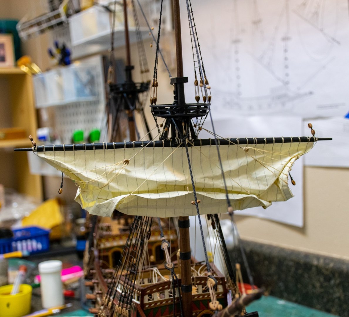
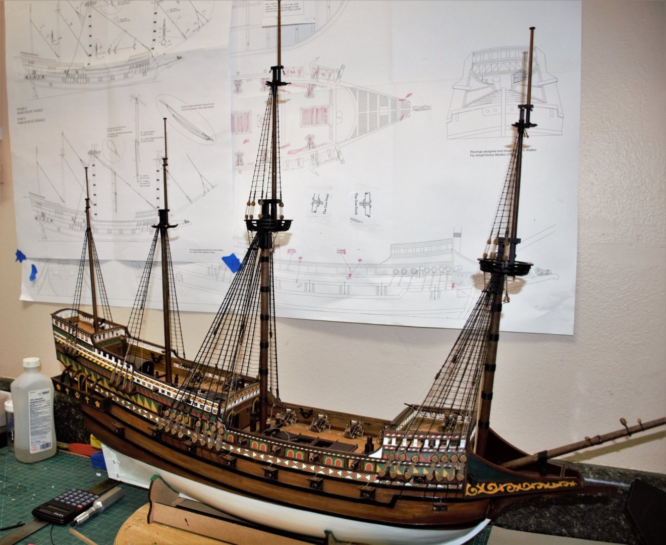
Greetings Time for another update. The stays are complete as well as the main stay tackle. Now on to the yards. They were all previously made with their attached block some time ago. As mentioned previously I am going to attempt to hand sails on all of them, partially drawn up but not furled (as if at anchor). Below is my first attempt. This required: making the sail with the bolt ropes and cringles; fixing the sail to the yard; attaching the yard to the mast with the halyard; rigging the clew and buntlines and lastly the martnets. here are a few pics of the final? result. I may need to work on the martnets to get them to hang a bit more naturally. Yard lifts, braces, sheet and tack line still need to be done. Comments / advice on the sail would be much appreciated. I plan on going into a bit more detail on the sail construction with the next one Jeff


- 159 replies
-
- 10
-
-

-
James, There is a cannon poking through both the fore and main shrouds. I had to be careful when doing the ratlines to be sure the line of fire was clear. Seems like a recipe for disaster should should a shot take out one of the lines but who am I to question Chris's design! jeff
-
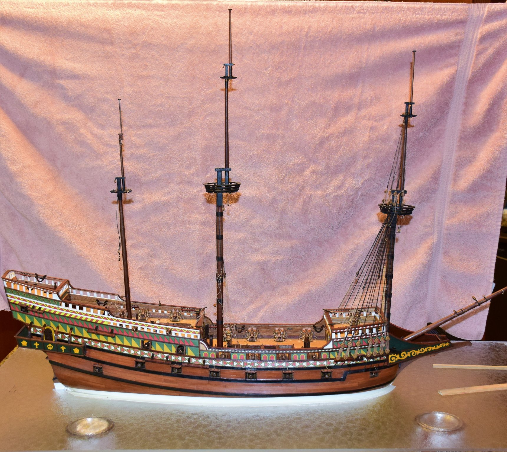
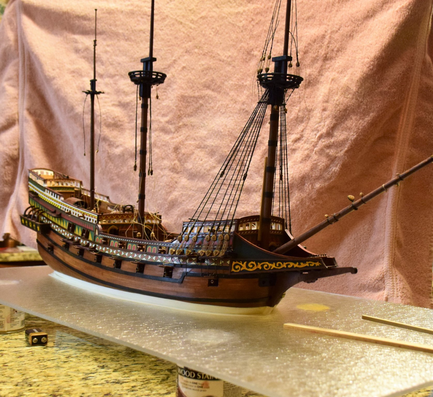
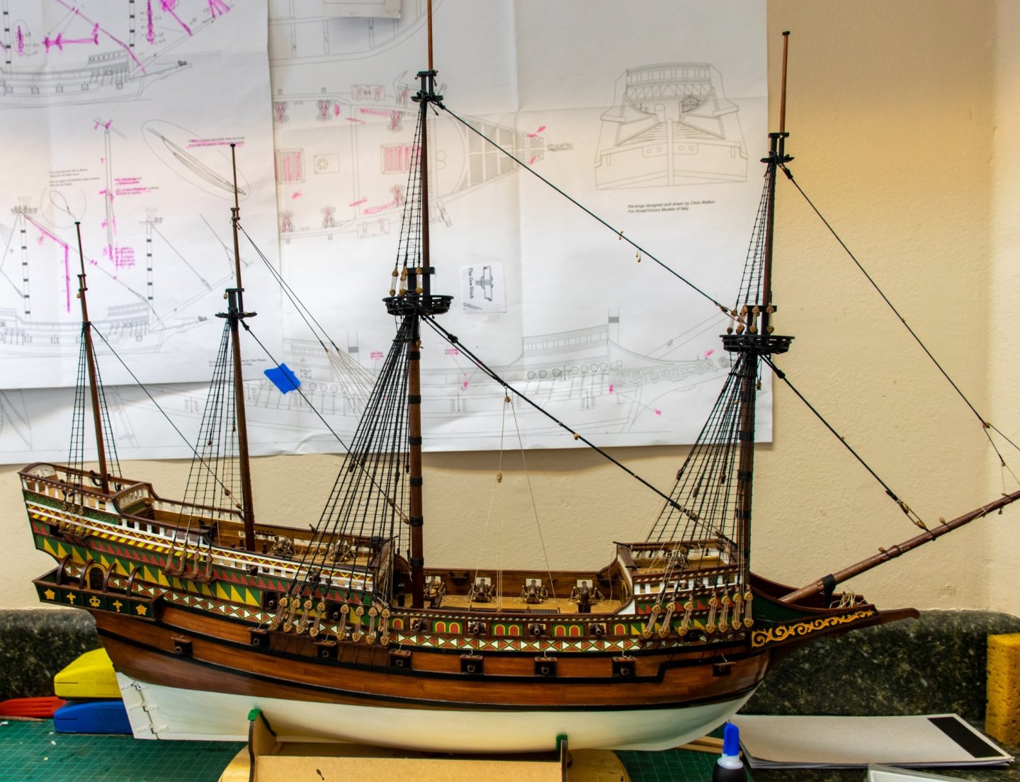
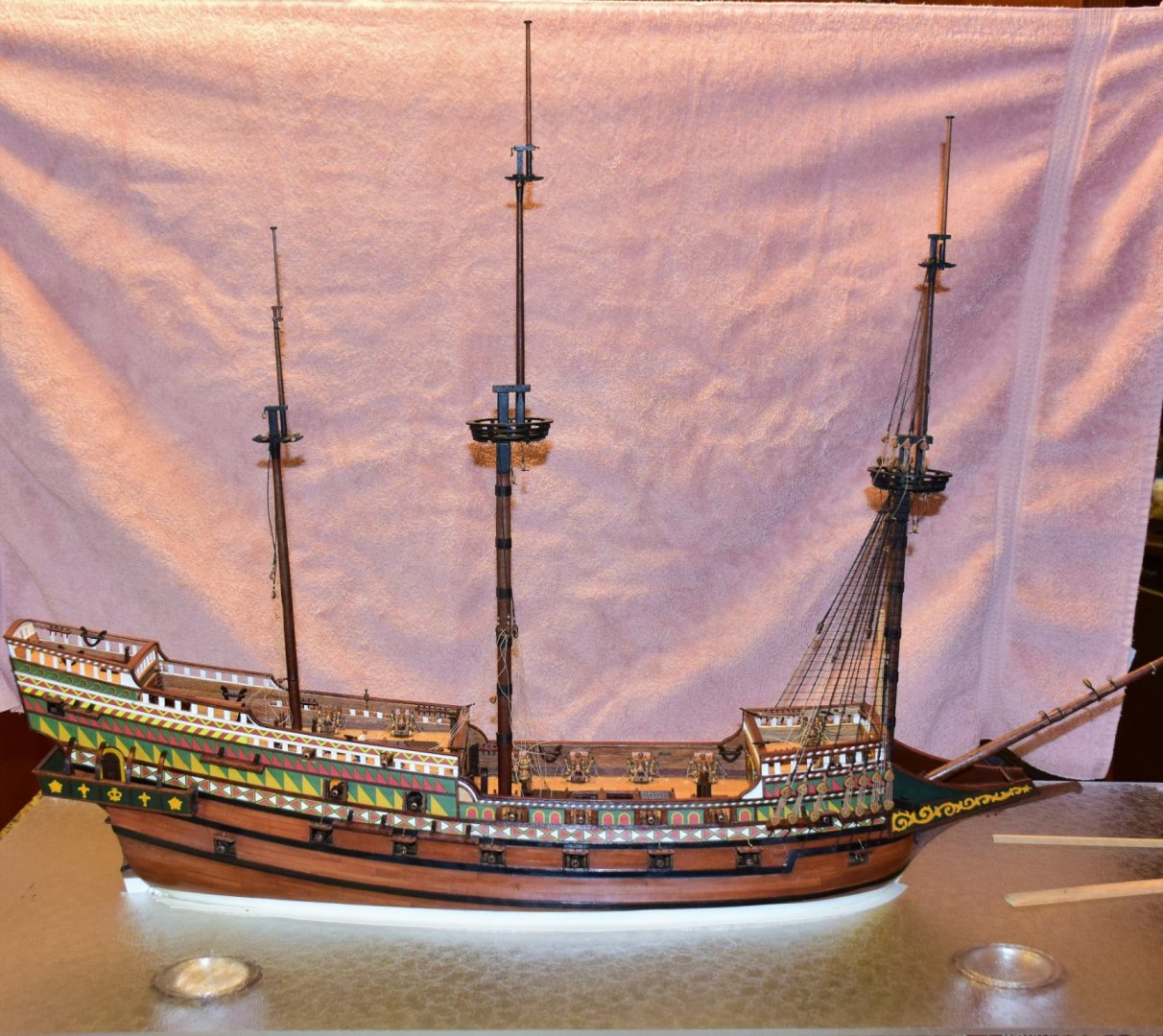
Greetings... Work on the Revenge has been a bit sporadic over the past few months. Now that the shrouds and ratlines are complete, progress should be a a slightly faster pace. Here is a photo of the ship at this stage... Next up are the stays. Photo below is the main stay (2 mm) with mouse (the part that goes around the mast is served) and it's collar which is served in it's entirety. Note the eye splice in each. The bowsprit gammoning has also been placed. I have to be very careful when turning the ship so as not to snap anything off! I'll post a few more pics after the stays are complete. jeff
- 159 replies
-
- 12
-
-
Congratulations on a job well done. I would consider this kit a difficult one for first build (especially with the bow planking) but you have done a great job. Are you planning on using the display nameplate, pedestals and base? Jeff
-
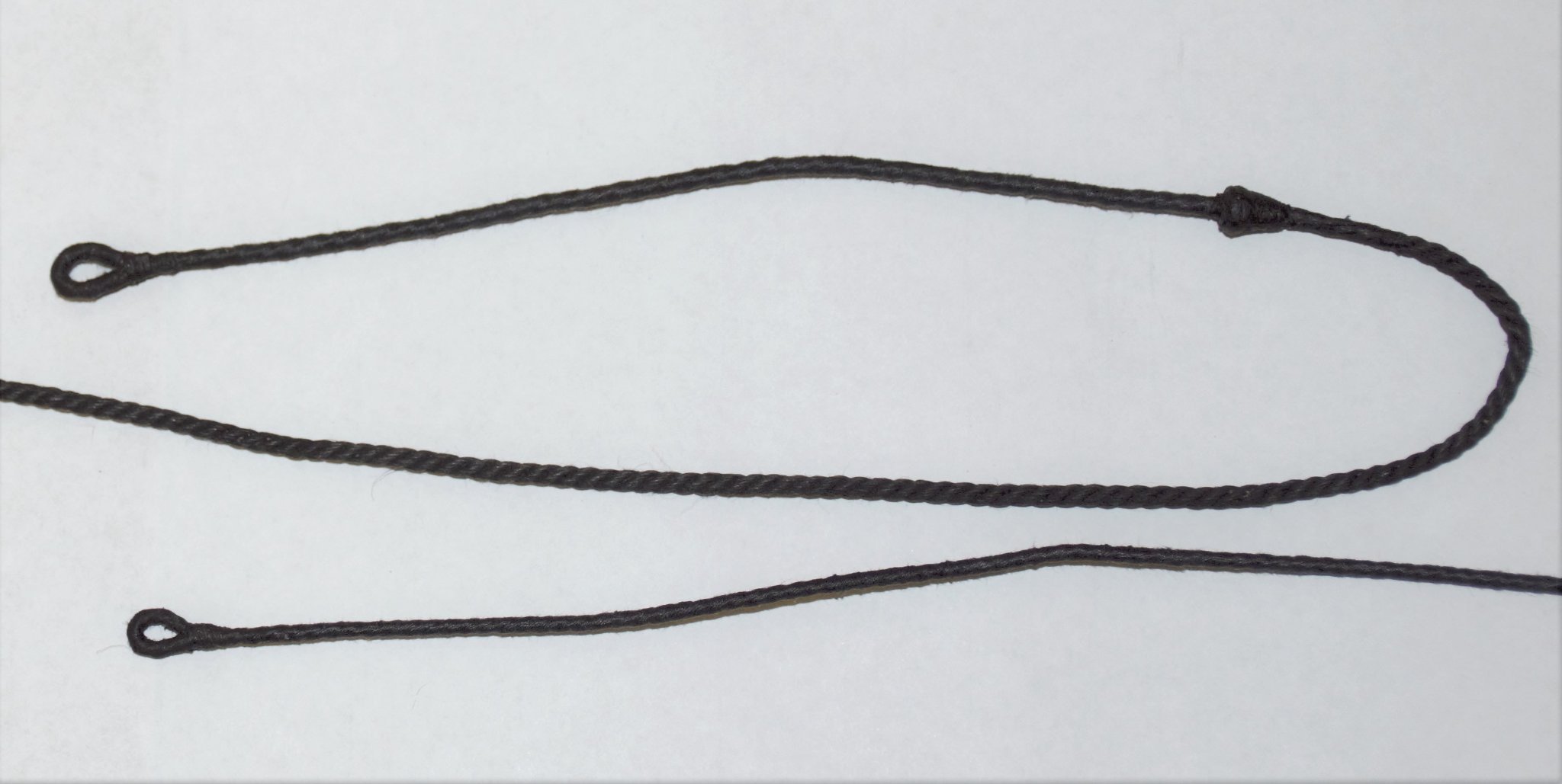
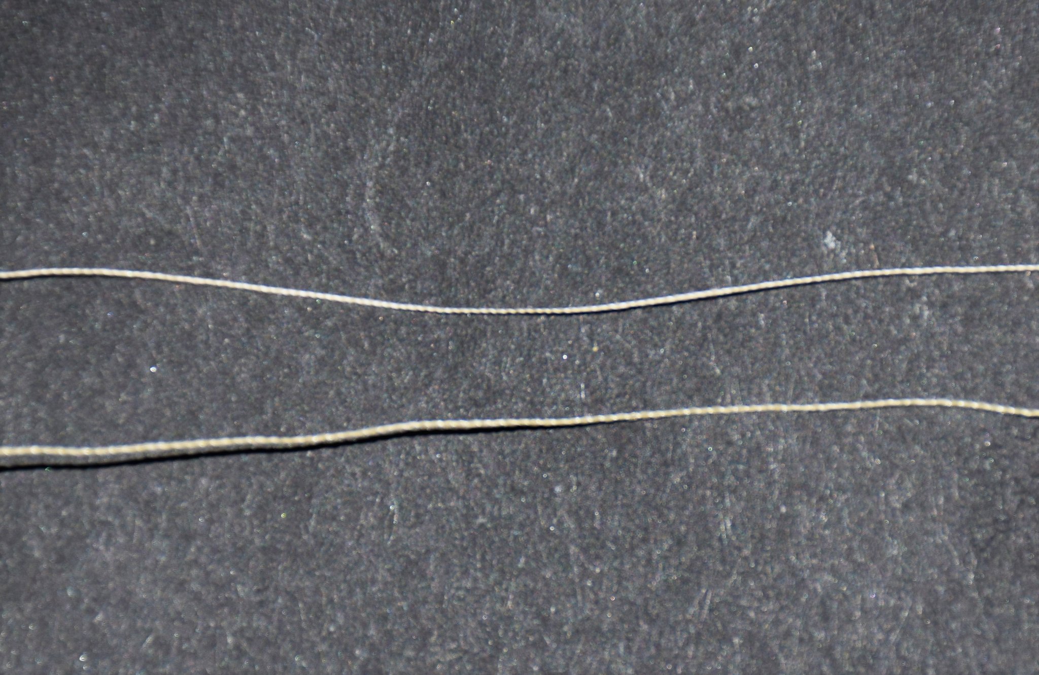
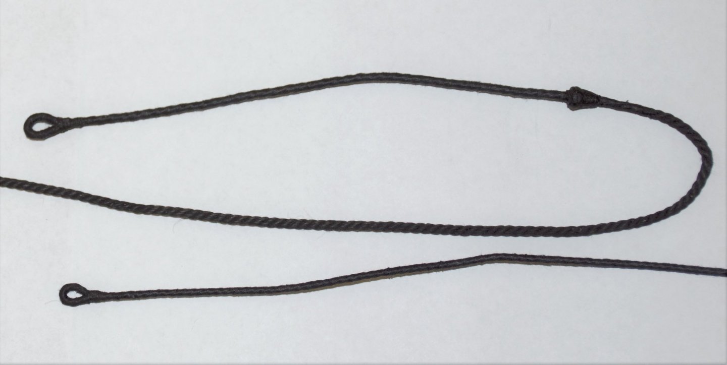
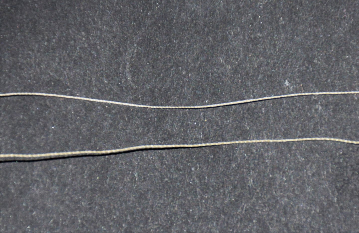
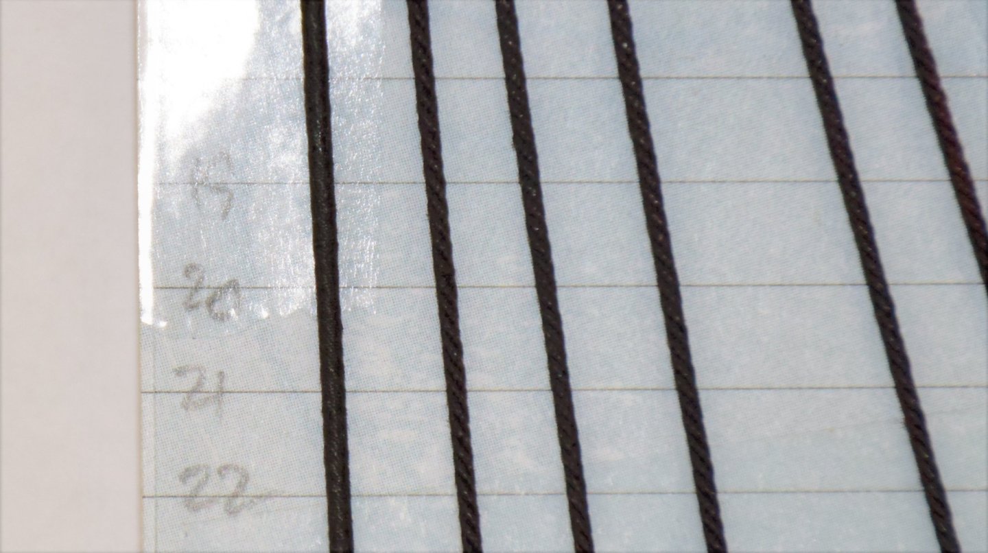
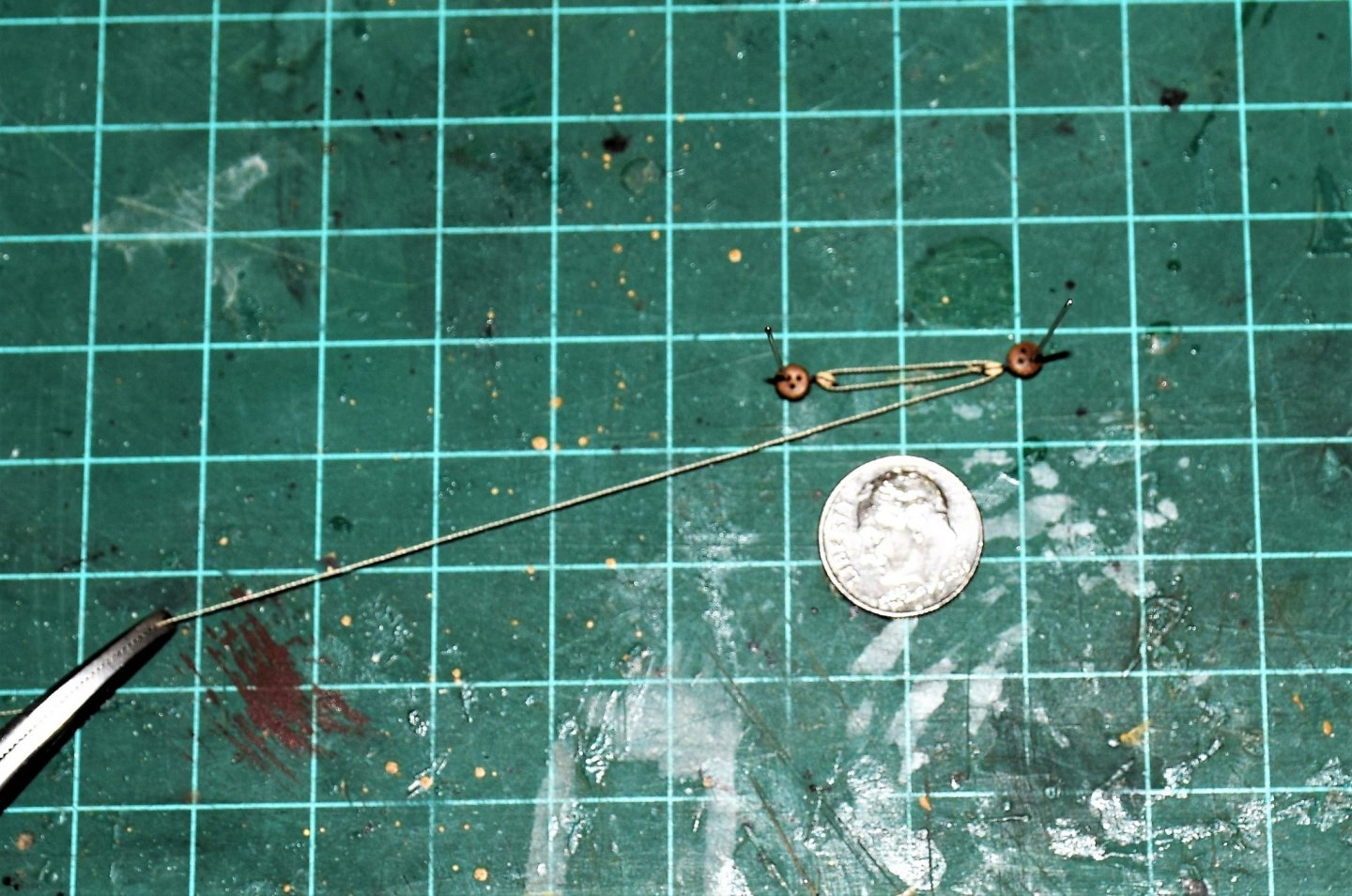
Greetings. I am currently working on the shrouds on the Revenge . I use Syren's serving device. In Chuck's instructions, he recommends 50 wt down to 100 wt line for serving. The smallest line I could find by a model co. was Amati at 0.1 mm. For serving the lines on the Revenge, I found some 50 wt black and tan line that is even smaller. See pic below - the top is to 50 wt line and bottom is 0.1 mm. a bit blurry but I think you can see there is a difference. For smaller scales (Revenge is 1:64), a smaller wt thread such as 60 or 80 could be used. Below is the port main shrouds with the forward most shroud served. As you can see, the served shroud is just a bit larger than the others and the serving can be barely seen. For scale, the distance between the horizontal lines used to guide the ratlines is 6mm. Jeff
-
This is one old kit. The year stamp on the ship's deck in 1959, 2 years older than me! Jeff
-
Well that did not take long. Revel kit already has an interested buyer Jeff
-
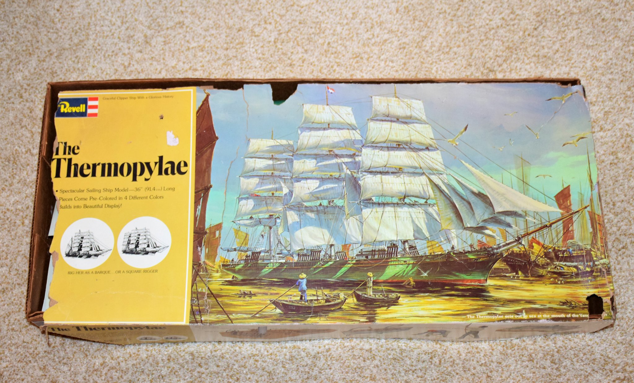
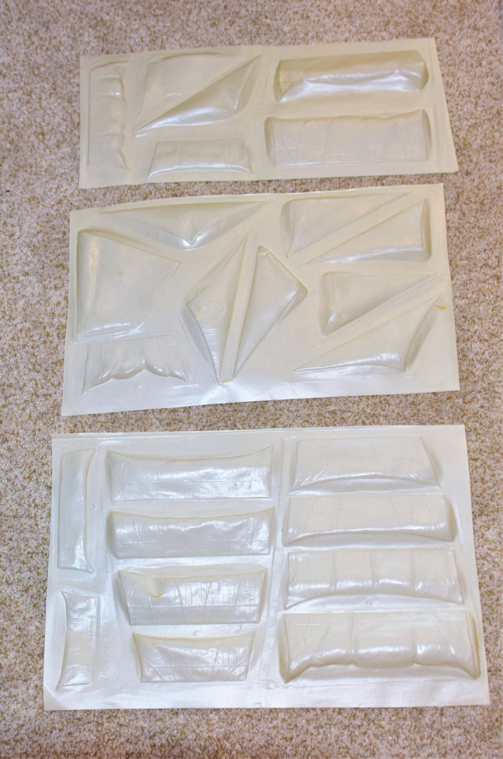
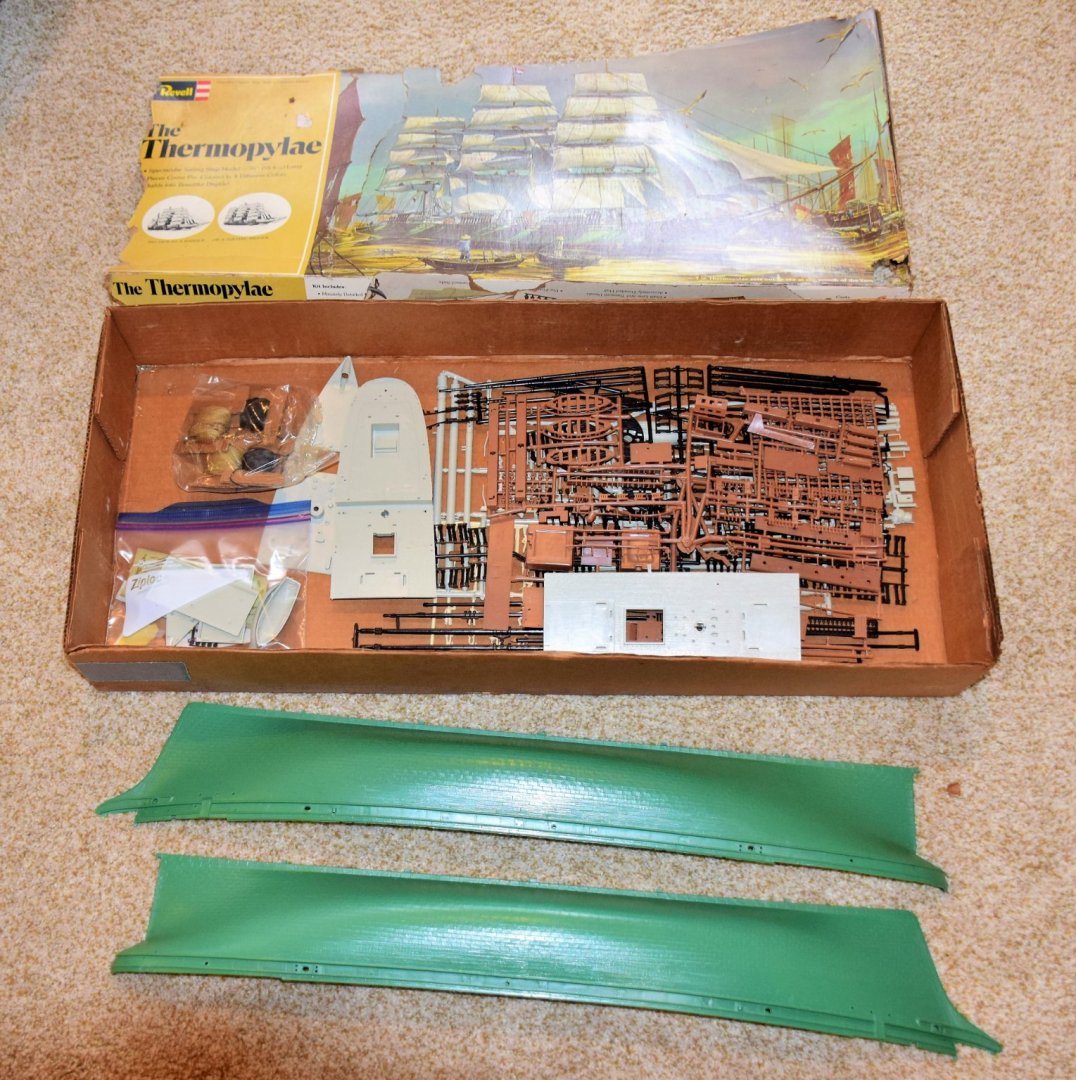
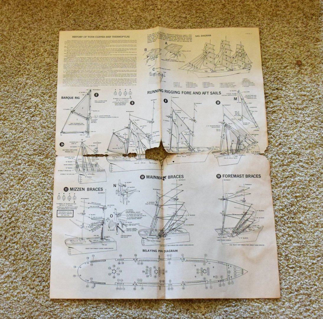
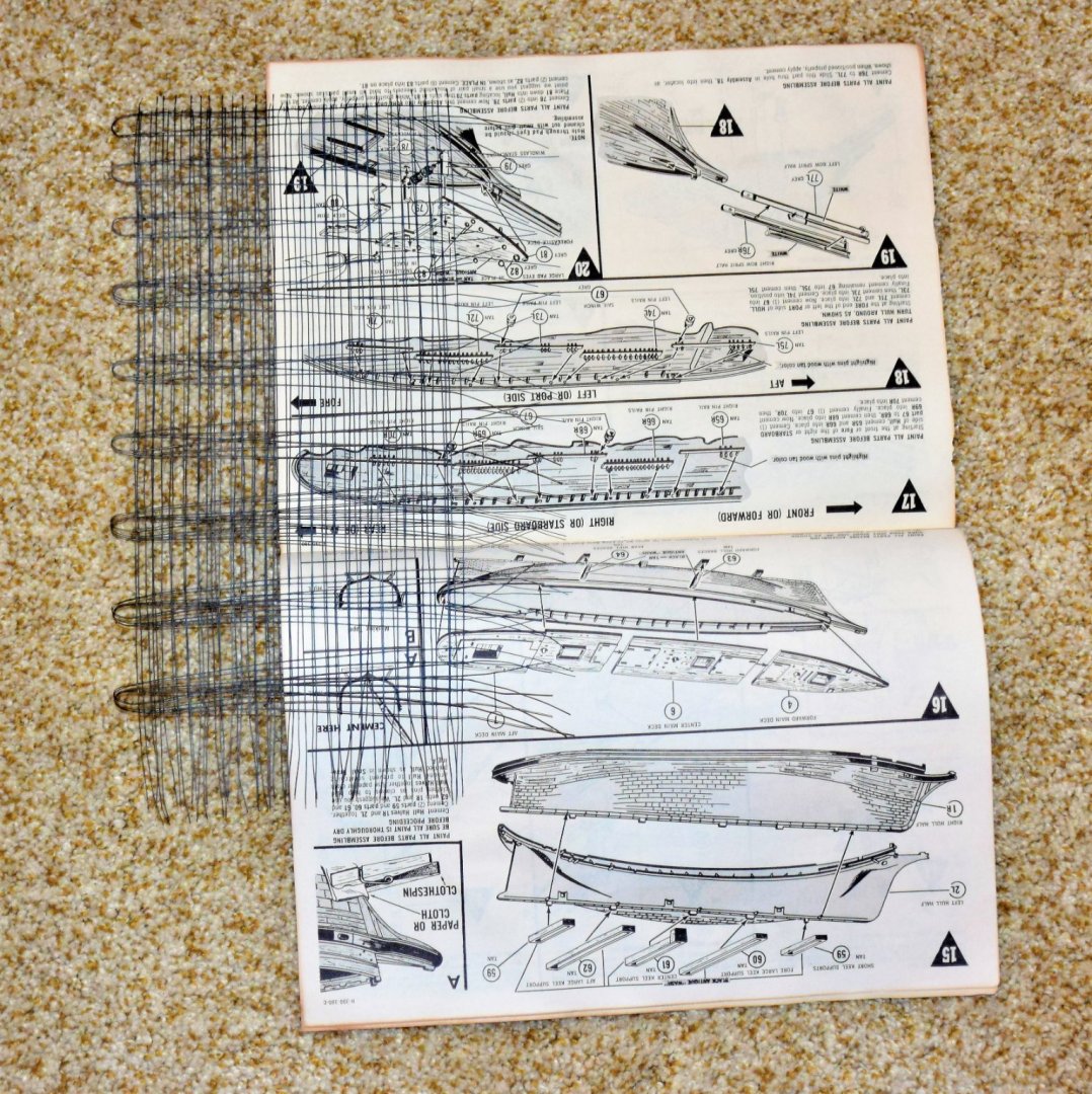
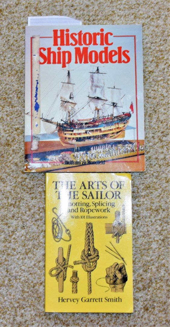
I have the following items for sale: Revel Thermopylae - this was given as a gift, however I don't do plastic models. The kit seems to be quite old and the box condition is poor (looks like it was kept in an attic for several years, maybe decades). I think all the pieces are present but there is no way to be sure. Very few came off the sprues and these I placed in a ziplock bag; the condition of the pieces seems to be good. The paper instructions are on the brittle side but not to the point of falling apart. Here are some pics" Price of the kit - free, just pay the postage. This will probable be pretty expensive to send overseas. This kit comes as is so if any parts are missing be prepared to manufacture them. The 2 halves of the hull and ships decks are in good shape next up, 2 books Historic Ship Models by zu Mondfeld. The book is used and there seems to be a publisher's error as it is missing pages 35-63 (they don't seem to have been pulled out). I have another copy (which is even more "used" ) so I will be able to supply the missing pages. Sale price: $5.00 plus postage The arts of the Sailor by Hervery Garrett Smith. This is a good reference for all sorts of knots and knot tying techniques. It is brand new. Retails for $12 on Amazon. Sale price: $5.00 plus postage. send me a message or post here if interested. I will need a destination zip code to estimate postage and we can discuss further by PM. Jeff


-
Greetings! work in progress on the main shrouds. futtock shrouds also mostly done on one side. I left the rope and seizing natural color so as to better see how the shrouds run and how they are seized to the main shrouds Jeff


-
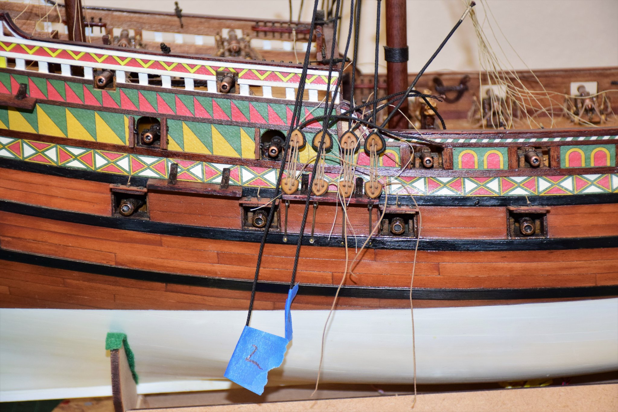
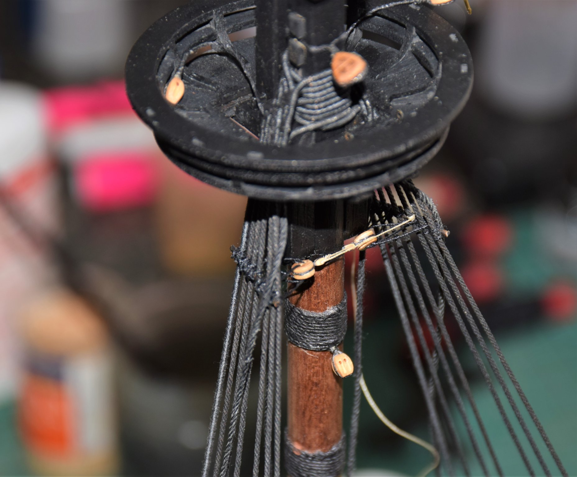
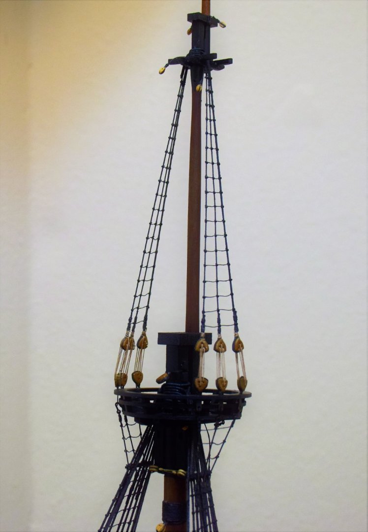
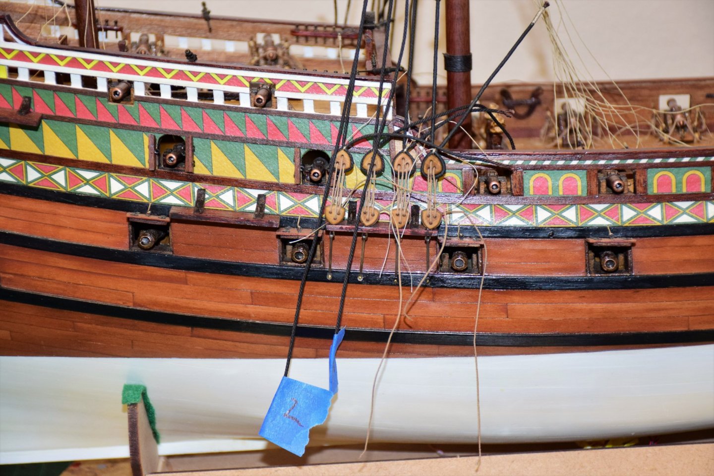
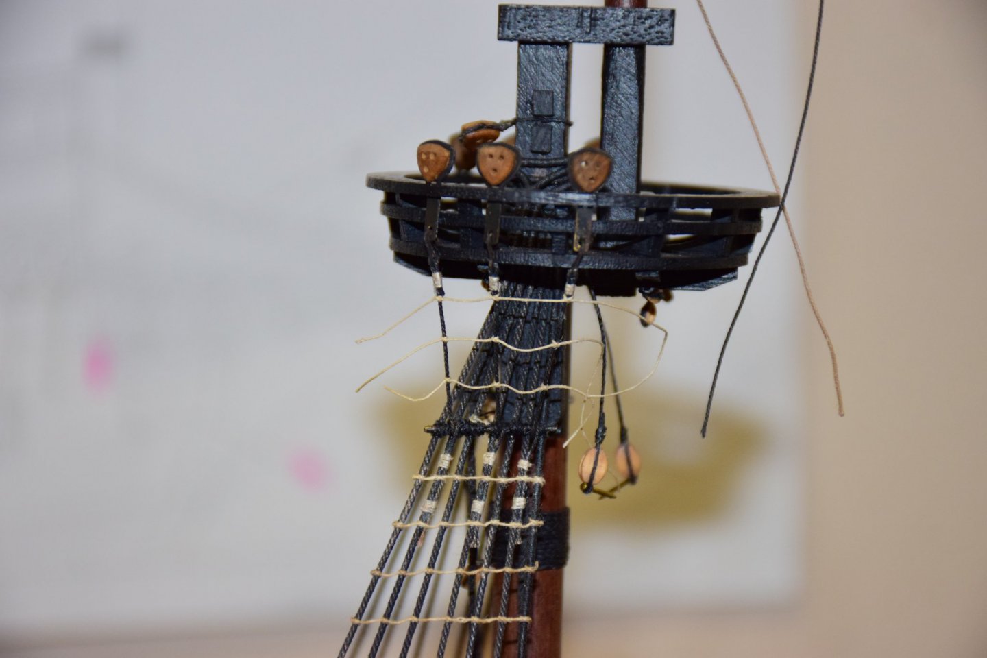
Greetings! Fore top mast shrouds now complete Onto the main mast. photo below shows the developing birds nest of lines while i do the shrouds and lanyards. The first 4 are in place and the aft 4 have been secured at the mast head and marked (see blue tape) so as not to mix them up when it comes time to do the lanyards. My process is to first serve the appropriate length that goes around the masthead, then seize it close to the masthead and the bring them through the top, alternating side to side beginning on the starboard. The shrouds are left long and are used to mark where the chainplate is nailed to the wale. The lower deadeye is then placed in the channel and the chainplate fixed to the deadeye and nailed to the wale (some trial and error required to get the correct length). An estimate is made for the correct shroud length and the eye seizing is placed and the shroud is tightened to the deadeye. With only the eye seizing in place, this can be adjusted later if needed. The lanyard is then placed and tightened and measurements taken to insure correct spacing. Only when all the deadeyes are in place and correctly space is the shroud seized and lanyard completed. also note the main tackles have been taken off the hook on the channel as they will be in the way for work on the shrouds and foot ropes. Jeff
-
Hi Chris, Would any of your boat kits or lanterns work for the Revenge kit you designed or would they be too "advanced" for that period? Jeff (build log for the Revenge under xodar461)
-
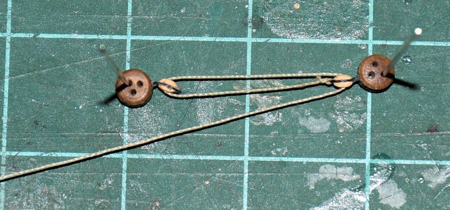
Greetings Kirill, your English is just fine in your posts and I have enjoyed reading them! Lower shrouds of the fore mast are now complete as are the futtocks. First 2 pics show how I keep the ratlines even. Next 2 show the final result. You may notice that the tackles have been undone on the photos above. They would have gotten in the way when the ratlines are placed so they were temporarily disconnected from the channel. This can be seen with the main tackles in the next 2 photos. The fore tackles were replaced upon completion of the ratlines. The ratlines have also been painted black. For the purist they were usually tan or light brown but I've always liked the look of black. The lighter color seems to be distracting. The next 2 pics show the foremast catharpins. These were a bit of a challenge to do as a small rope goes through each dead eye opening and then is tied to the shrouds. The deadeyes are 3mm and the blocks are 2 mm. The lanyard (0.1mm rope) is supposed to be tied to the space between the block and deadeye but I tied it to a shroud above the futtock stave (pic 3 below). Work in progress on the futtock shrouds below As I've said in an earlier post, I would like to ultimately display the ship at anchor in the simulated ocean. Here is what I have so far - 5 mm plexiglass with the waterline cutout. Eventually it will be painted and some water details added (first to be done on a test piece or 2). This is still quite some time in the future. until next time, Jeff


-
Hi Jonathan, After reviewing you last few posts and Kirill's replies, I thought I would add my 2 cents. One reason things might not look "right" may be due to the thickness of the futtock shrouds. The kit plans call for 1.3 mm rope for the main fore shrouds and 0.75 mm for the futtock and topmast shrouds. The same diameter rope is called for on the corresponding main mast. However, the rope sizes for the shrouds are slightly different from the fore to the main and the sizes used for the kit instructions seem to be too big for the scale of the ship. Sizes of all rope used for rigging is not arbitrary, it is calculated based on the thickness of the main stay which is itself based on the thickness of the mainmast at the deck. 2 good references are Historic Ship Models by Wolfram zu Mondfeld and The Masting and Rigging of English Ships of War 1625 - 1860 by James Lees. So, here are the calculations: the thickness (or diameter) of the mainstay is typically 0.166 x (diameter of the main mast at the deck). This is from zu Mondfeld. For the Revenge, that would be 1.66 mm. The kit calls for a 2mm line and I thought this looked better and is not too far off (also if I used 1.66, everything else would be measured using this value leading to smaller shrouds, backstays etc which I thought would make the overall rigging look too "thin"). Another point to remember with ropes is that in many reference books the size of the rope given is actually the circumference whereas the sizes given in kit instructions are the diameter. Everything below is rope diameter. According to the tables found in zu Mondfeld's book, the fore shroud measures 40% of the main stay and the futtocks and topmast shrouds are 18 and 20 % respectively. That would translate to 0.8 mm for the fore shroud (I used 0.88) and 0.4 mm for the topmast shrouds (I used 0.45 for the topmast and the futtocks as well as there is only 2 % difference). You can see that this is almost half the size of what the kit call for and thus may be why thing don't look right. The main shroud is 50 % of the main stay (1 mm vs kit 1.3 mm) and the futtocks / topmast would be 20 % / 25 % (.4 mm and .5 mm vs kit .75mm). All rope sizes can calculated from the size of the main stay, both running and standing rigging. One rigging that is constant is the size of the ratlines - standard size is 1.5 inches circumference so at a scale of 1:64 that would be 0.18 mm diameter (kit calls for 0.25). I usually err on going smaller as ratline that are too large just don't look right. So even using the kit size for the main stay of 2 mm, the remaining rigging sizes (at least on the set of plans I am currently working on) are too thick. It may seem complicated but it is not really if you just take it one line at a time. I simply figure out how big each line should be as I get to it and see what I have in stock that is close. Also, you are not so far advanced that restarting the rigging (if you chose to do so) would not be too difficult. And finally, I have an extra copy of Historic Ship Models and would be happy to sell it for you for a nominal fee + shipping (depending on where you live). For some reason, due to a publishing error, it is missing pages 33-64 but I could get those pages to you with the book. Just send me a message if you are interested. Jeff
-
Hi Kirill I appreciate your help and loved the historical paintings you provided. I do plan to put sails on. I plan on having the ship displayed at anchor with the sails partially drawn up, maybe the mizzen or bonaventure sails furled. I plan on using silkspan as the sail cloth provided in the kit is out of scale (much too thick). I have a sheet of plexiglass with the waterline cut out that the ship will sit in that will eventually be finished to simulate water (I hope). I have a phot of this that I will soon post. Never have done sails so that will be an adventure. The kit provides pretty good sail plans and I have several references to help with the rigging if the kit plans are lacking. Jeff
-
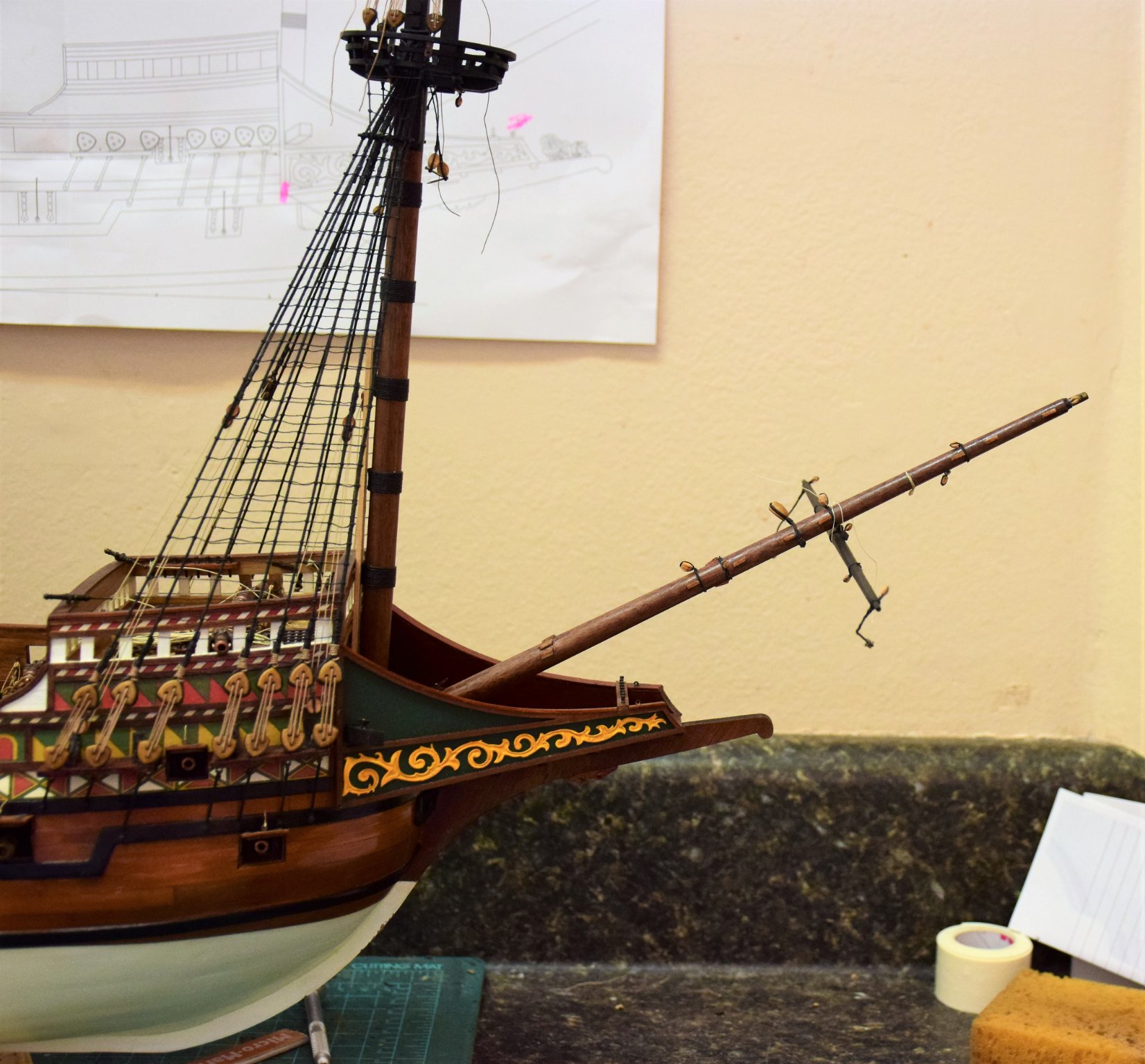
Hi Kirill Your second post really got me thinking so i decided to check things out. First I marked where the bowsprit met the deck and then measured that compared to the height of the foremast from deck to cap as you suggested. I found that the bowsprit was just a few MM short from the top of the cap so I think I have the correct length. So then I placed the bowsprit in it's deck opening and hung the spritsail yard and this is what I came up with... This seems to be close to the correct position as seen in your reference photos. I think the problem lies with the prototype on the box as I agree that the spritsail yard seems to be in the wrong place (as it is on my kit box top). Let me know what you think and thanks for your input Jeff

-
Hi Kirill Thanks for your input on the bowsprit. BTW, your galleon is amazing. The length of the bowsprit in kit is 363 mm. An often used reference for me is Historic Ship Models by Wofram zu Mondfeld. According to his tables of mast dimensions, an English galleon of 1570 would have a bowsprit length of 2.235 x the ship's beam. Using my model as a reference, I measured a the beam to be ~160 mm which would translate to a bowsprit length of 357 mm. The diameter of the bowsprit at the deck would be 0.028 x L of bowsprit, or ~10 mm, which is what the kit calls for. I did not do this for all of the masts and yards as this kit was designed for Amati by Chris Watton, a master model designer (see his website at Vanguard Models). His models are first rate and I trust that he did his research when designing the kit. It is good to know that his measurements are accurate with the bowsprit as I am sure they are with the remaining masts and yards. Jeff


.jpg.75cf4d73214a7f7d43662b034f7fff42.jpg)
.jpg.6cd9d3b745001594c77a3146a7940ad3.jpg)
.jpg.830a1019e3db8dbe0642d2d276304a58.jpg)