HOLIDAY DONATION DRIVE - SUPPORT MSW - DO YOUR PART TO KEEP THIS GREAT FORUM GOING! (89 donations so far out of 49,000 members - C'mon guys!)
×
xodar461
-
Posts
172 -
Joined
-
Last visited
Content Type
Profiles
Forums
Gallery
Events
Everything posted by xodar461
-
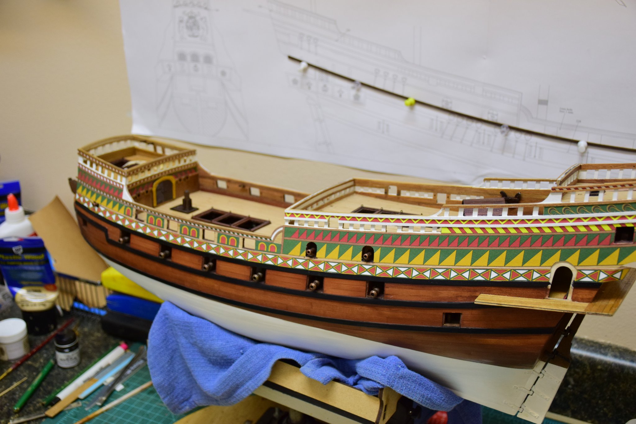
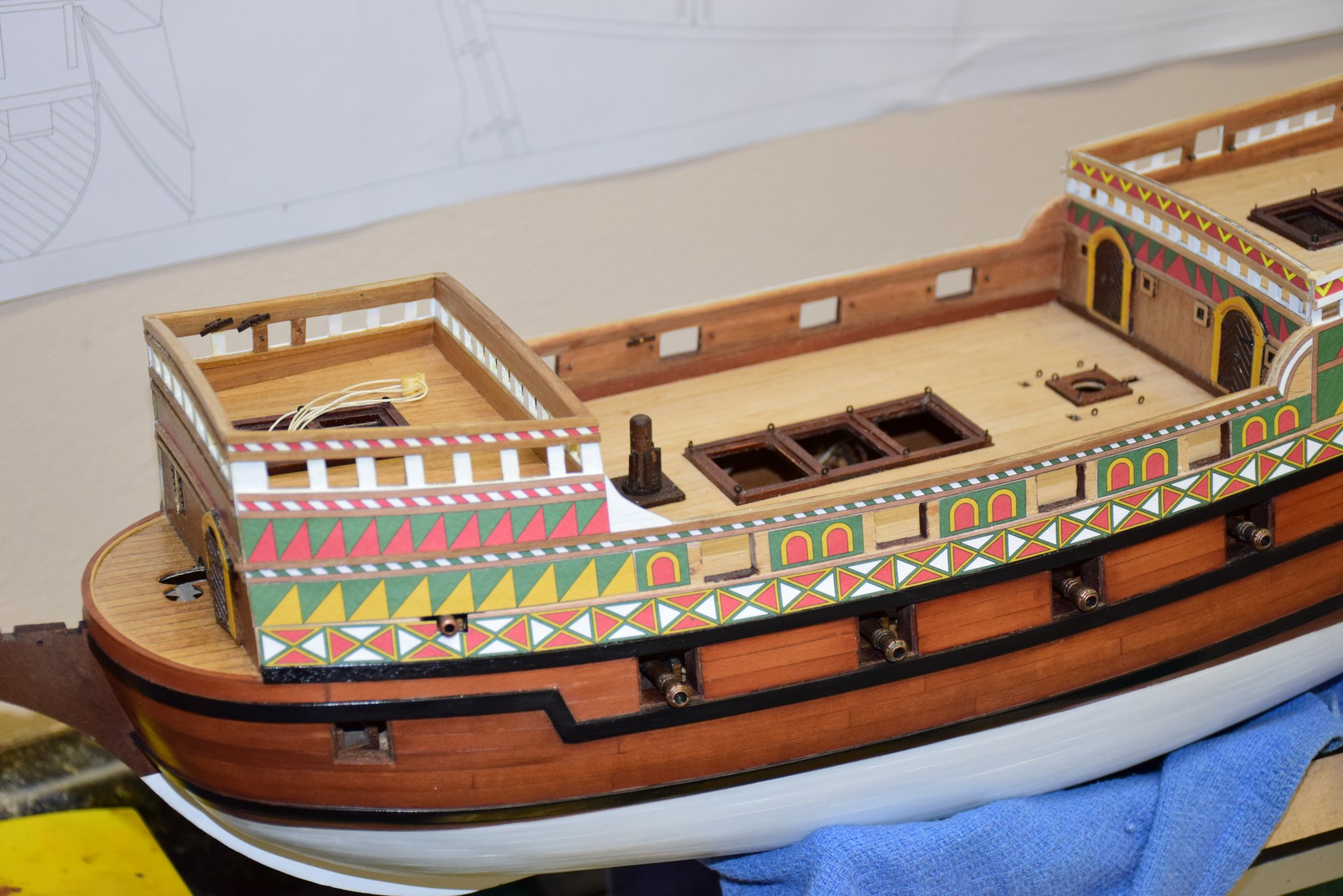
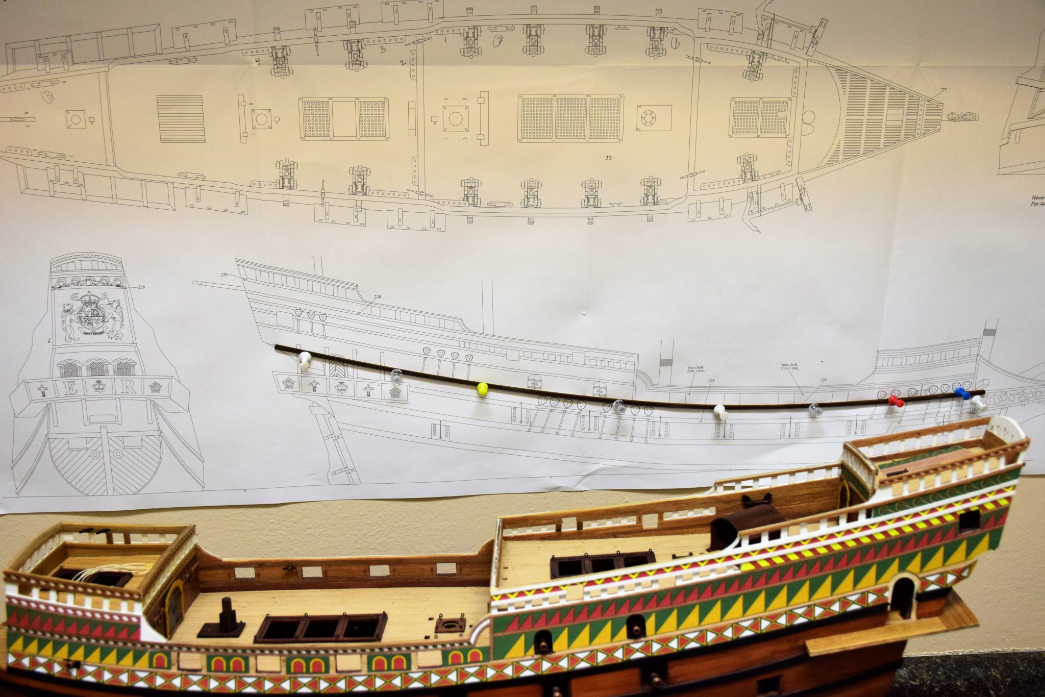
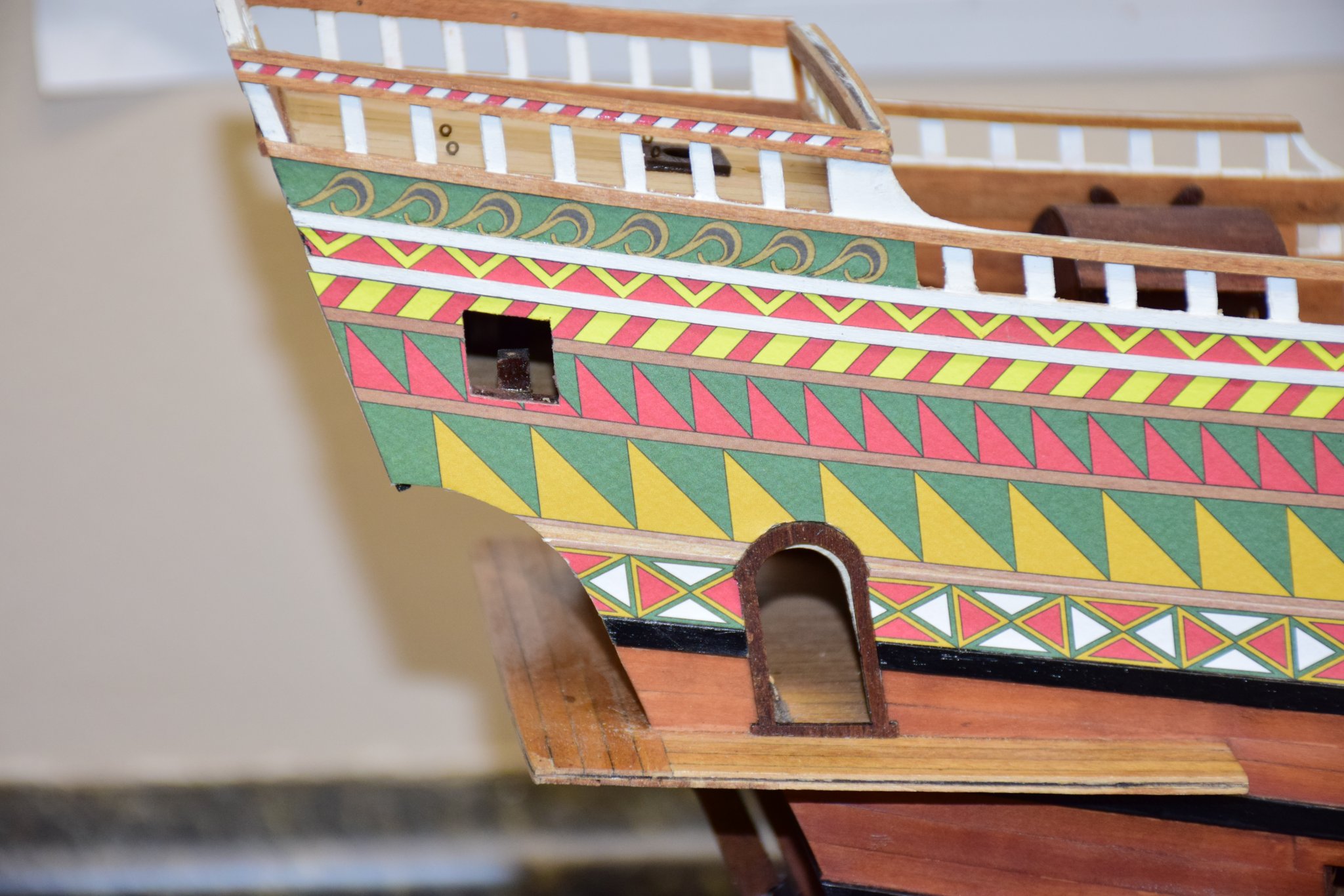
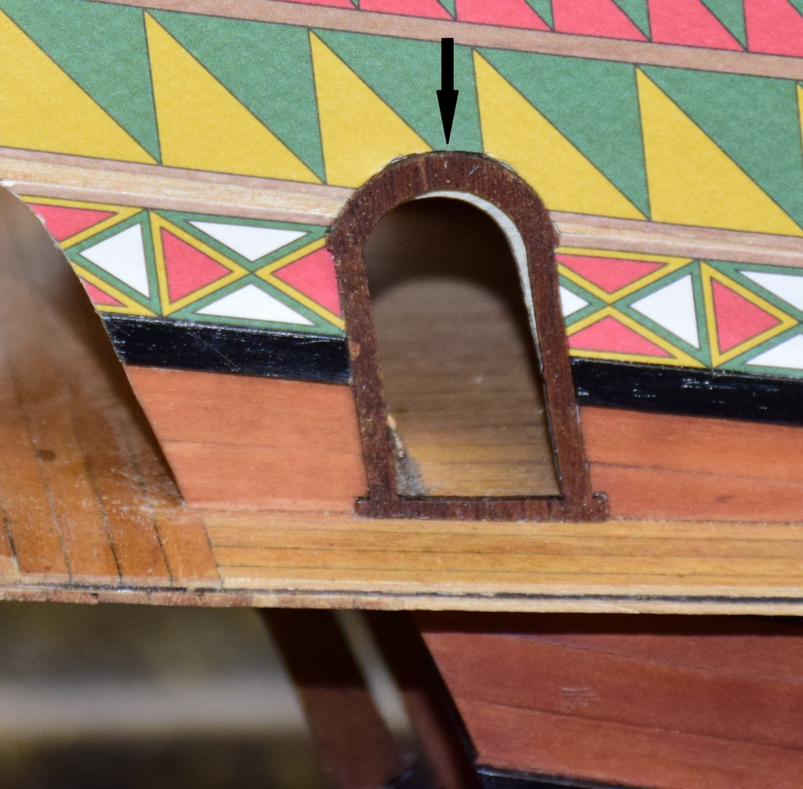
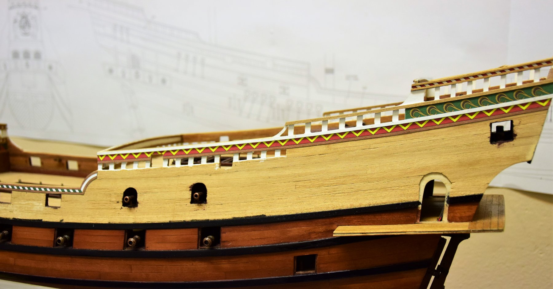
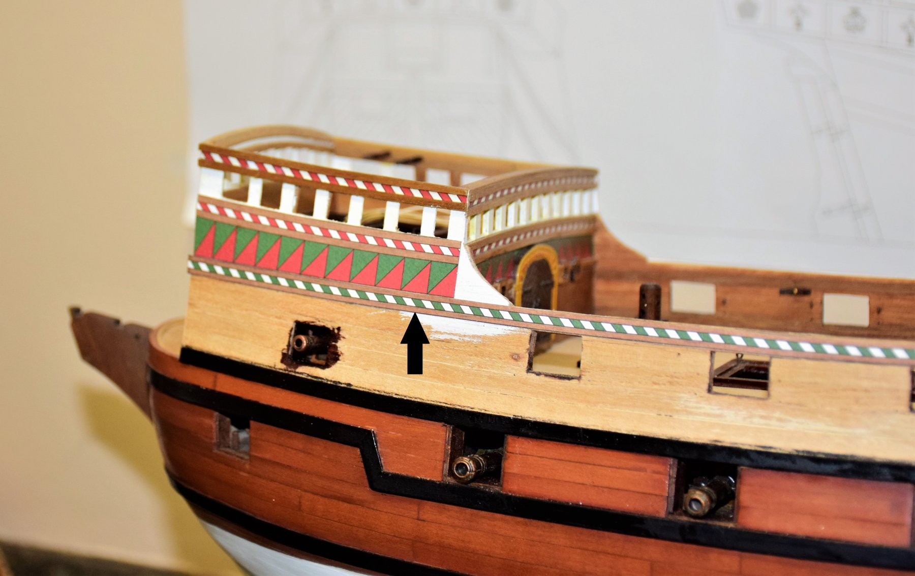
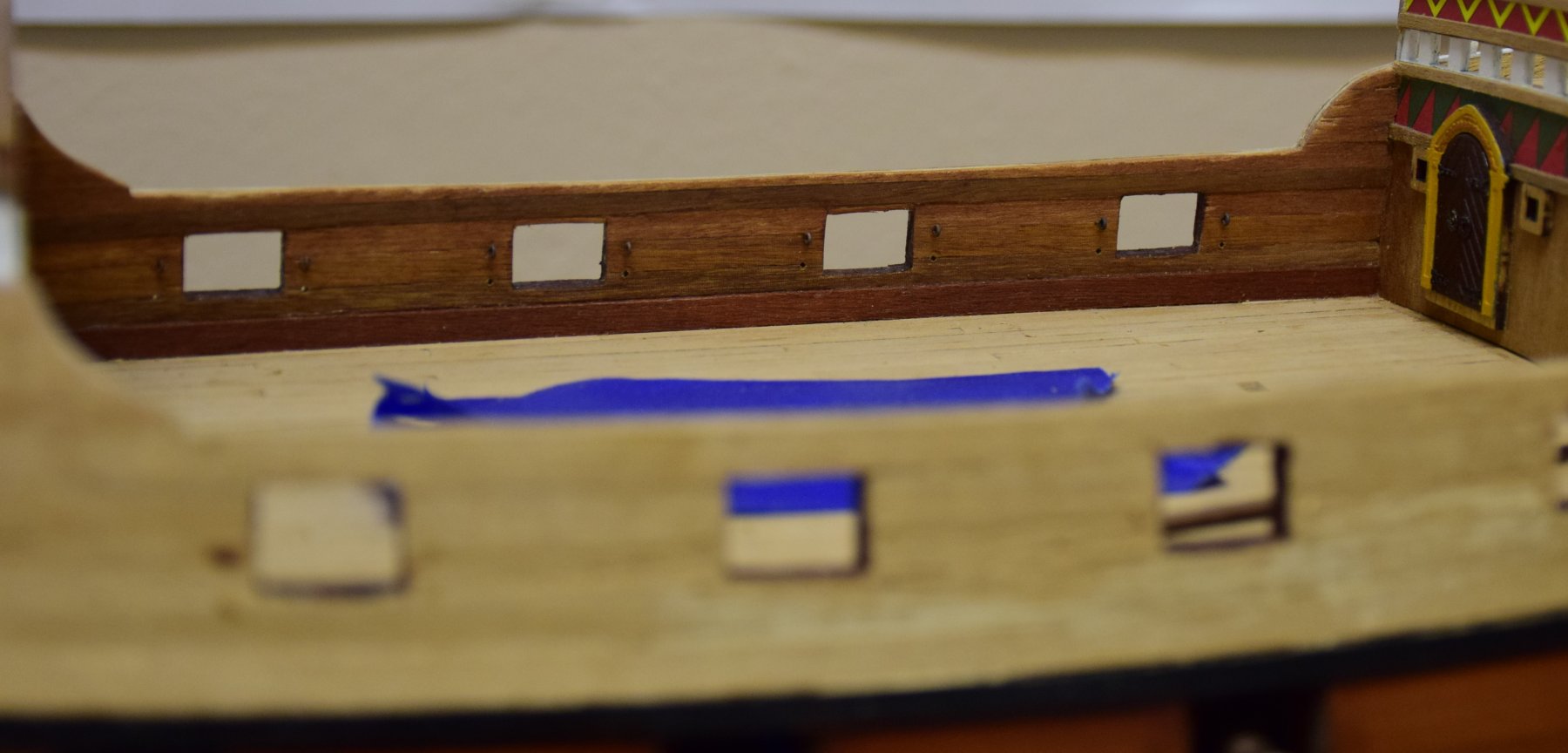
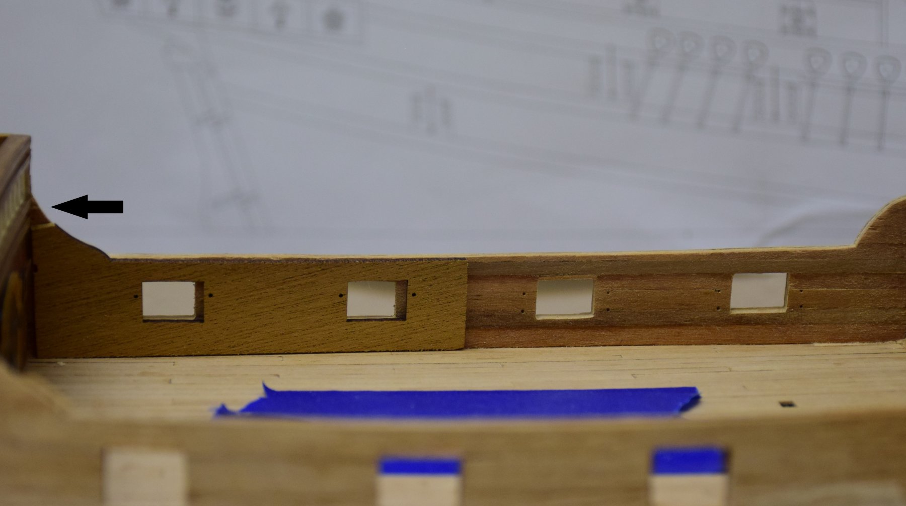
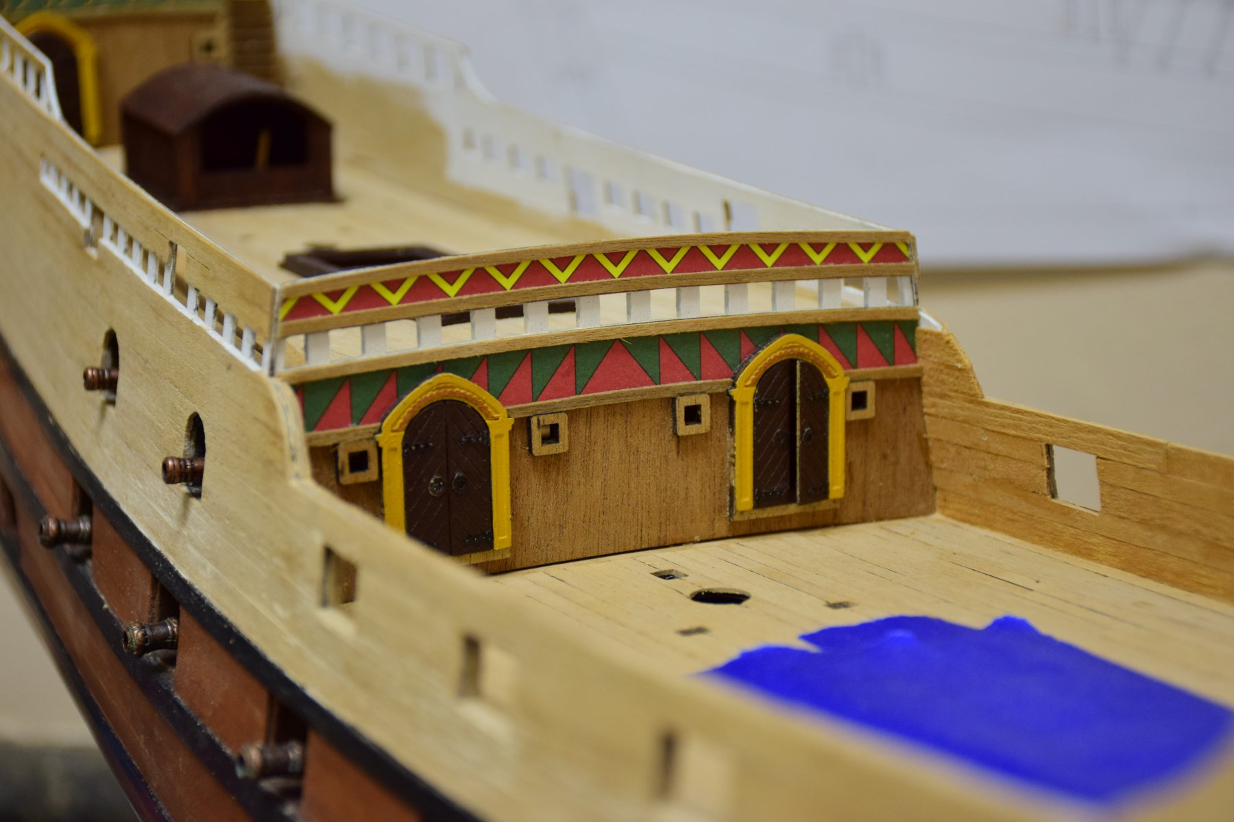
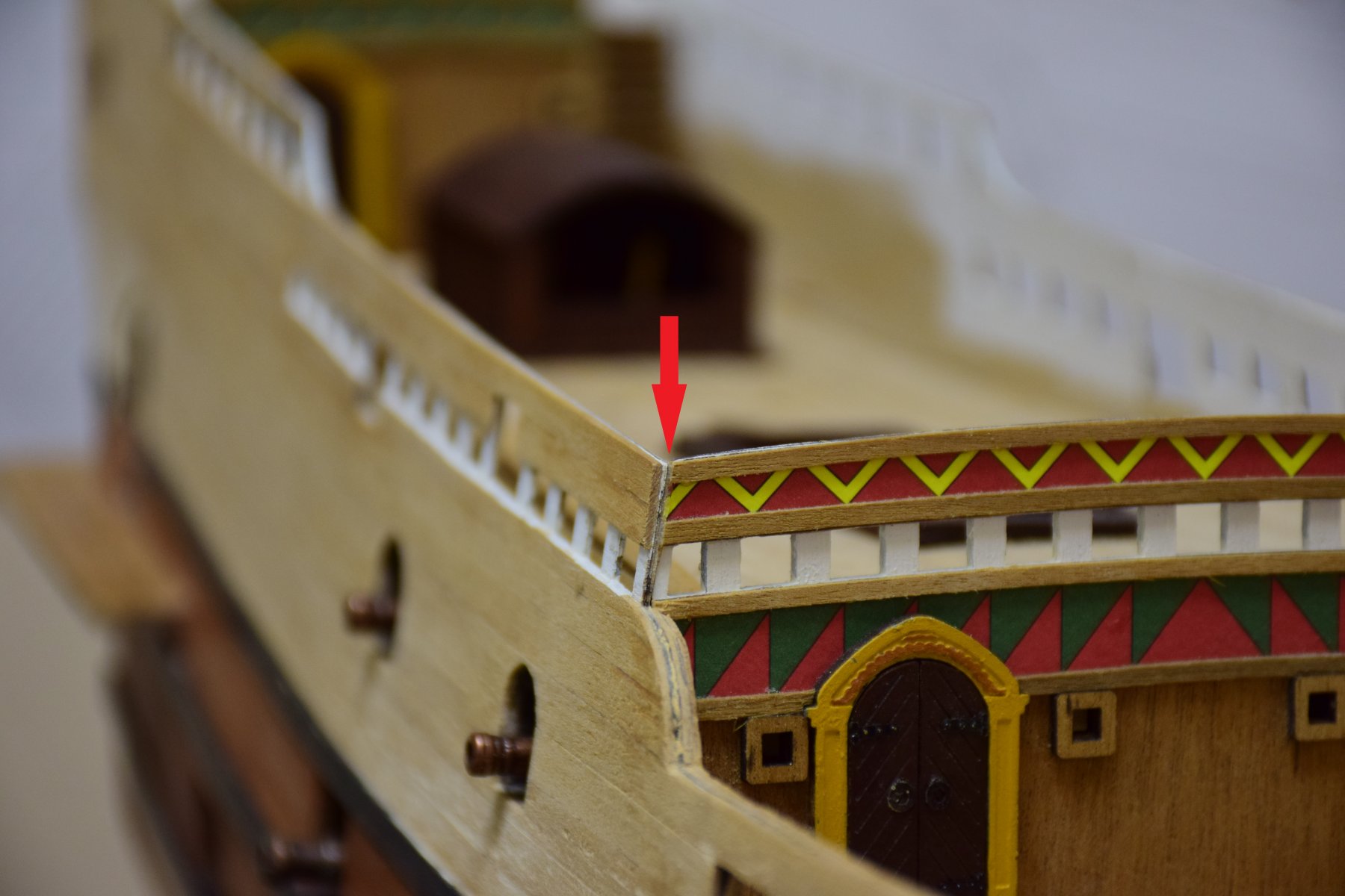
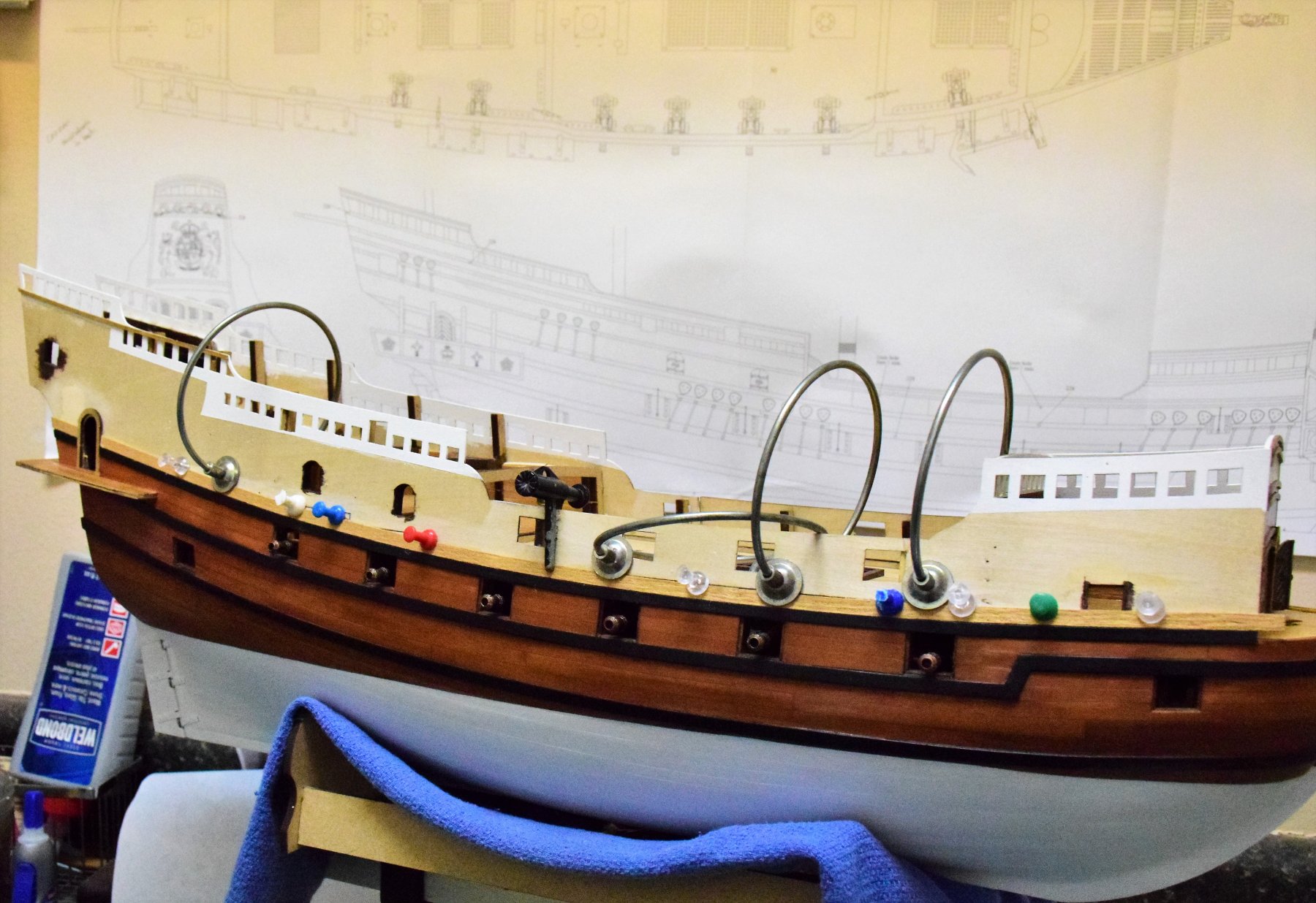
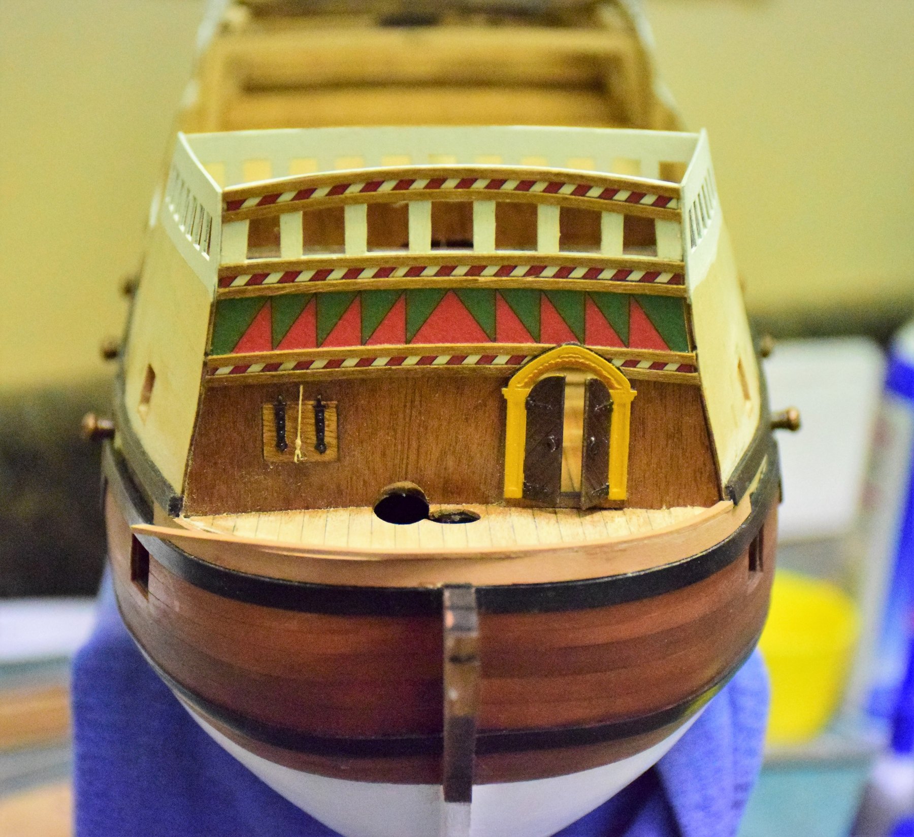
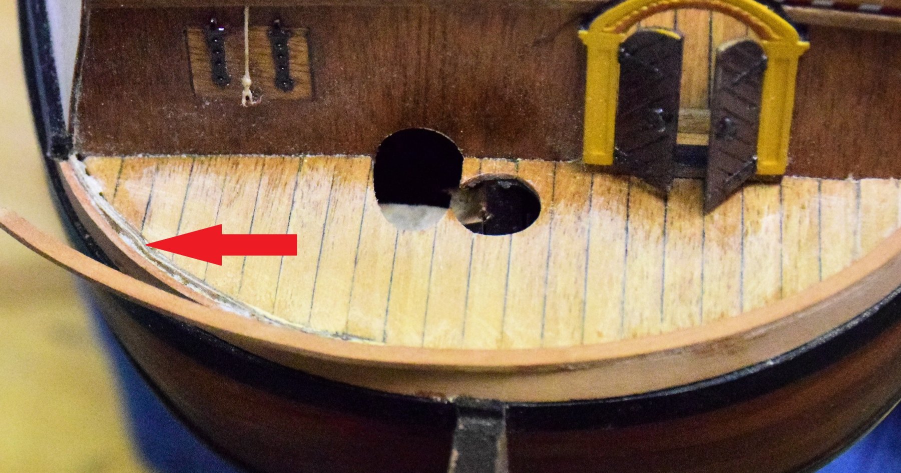
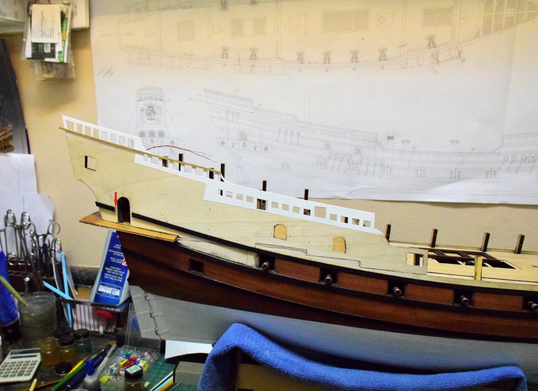
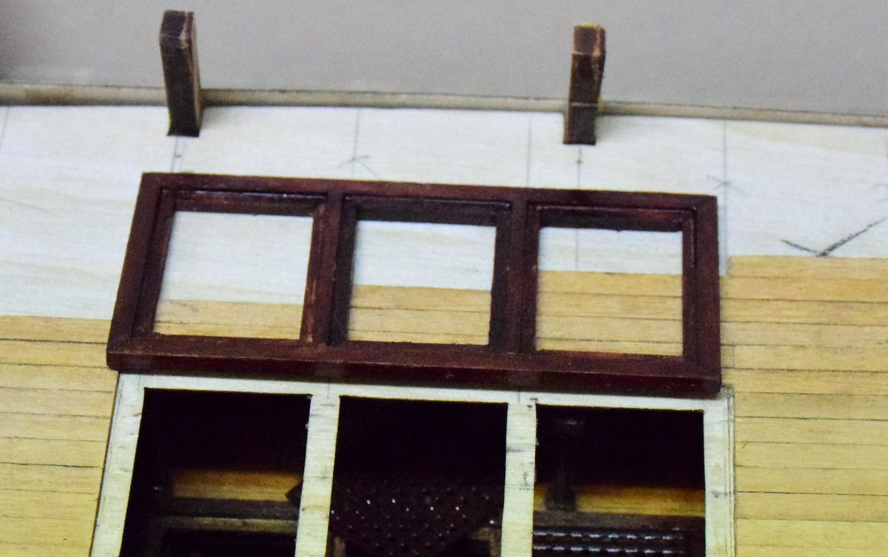
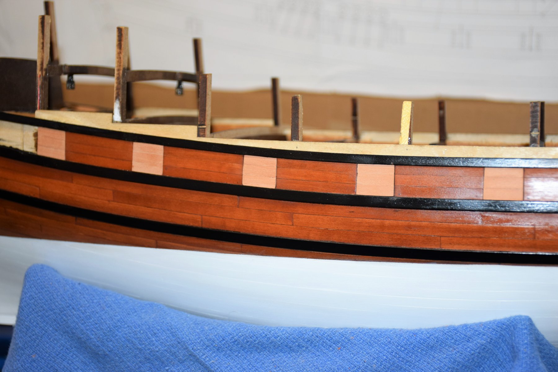
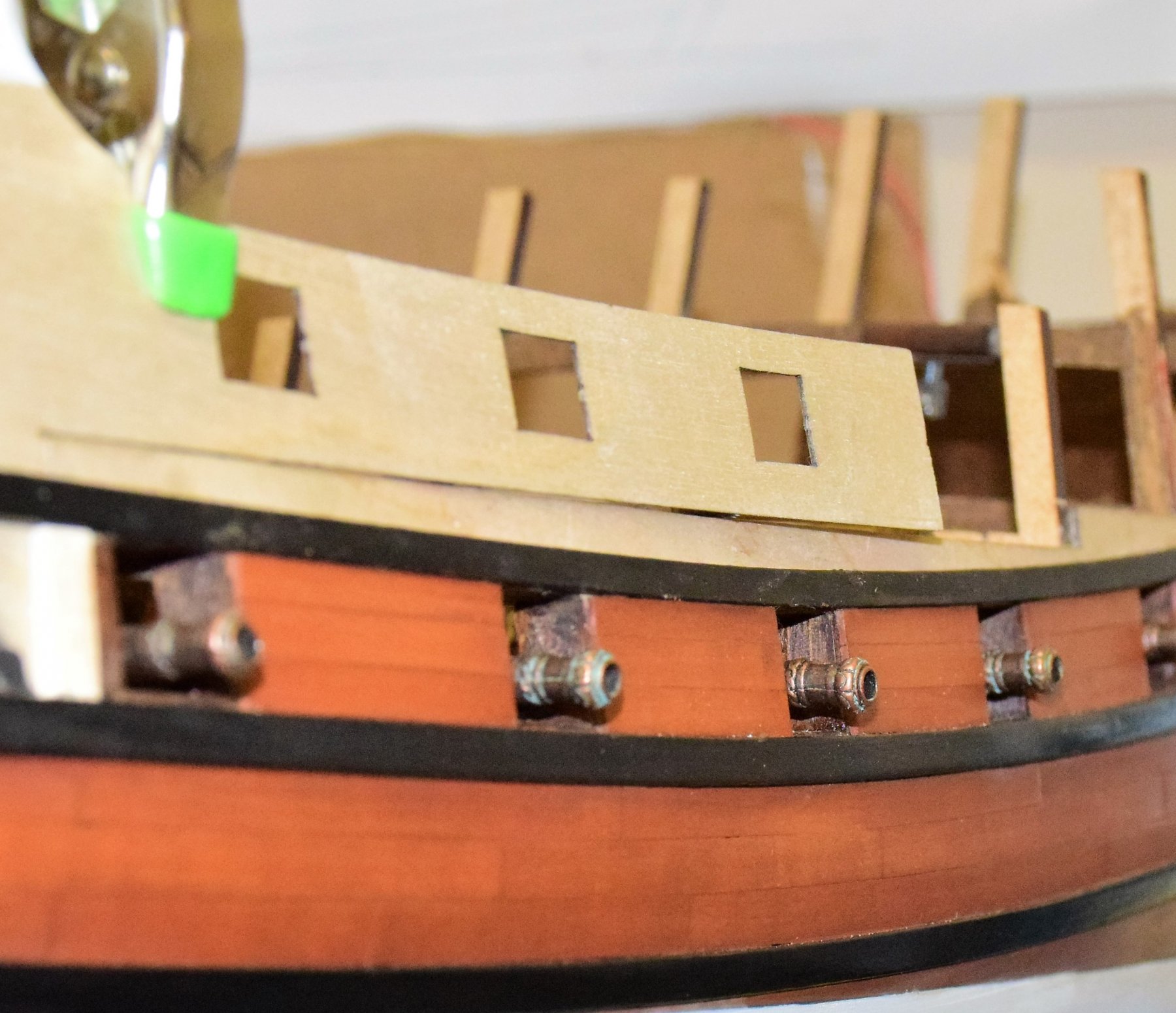
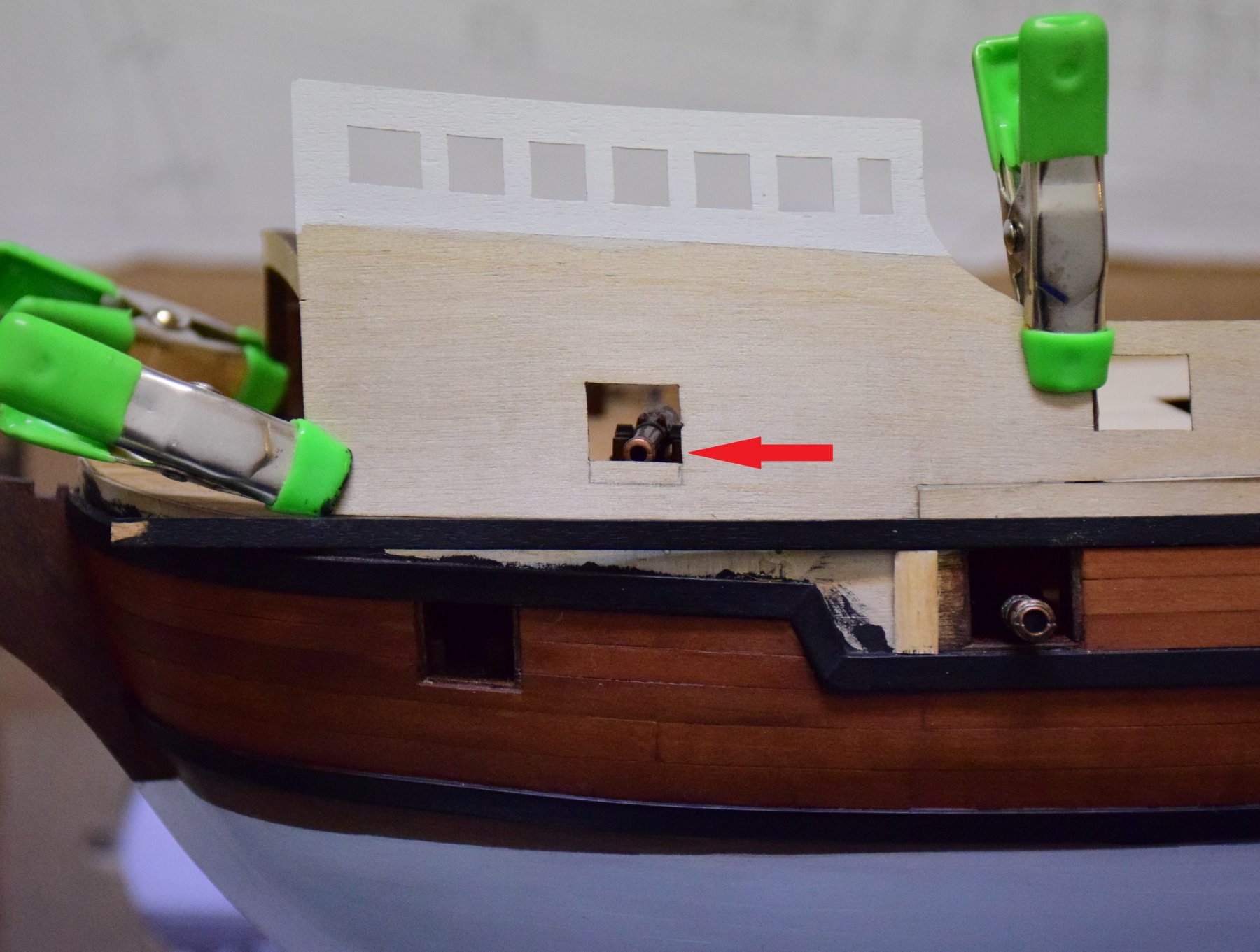
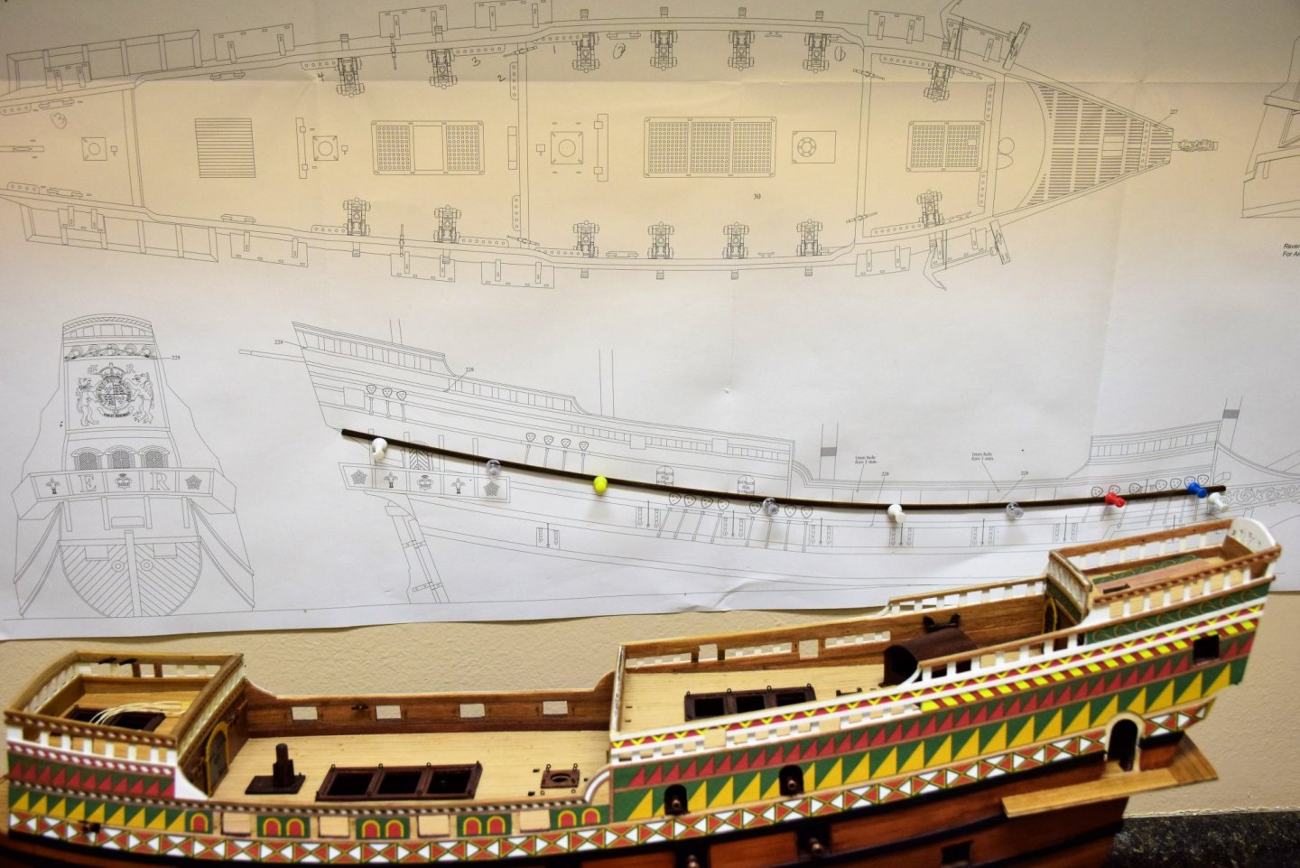
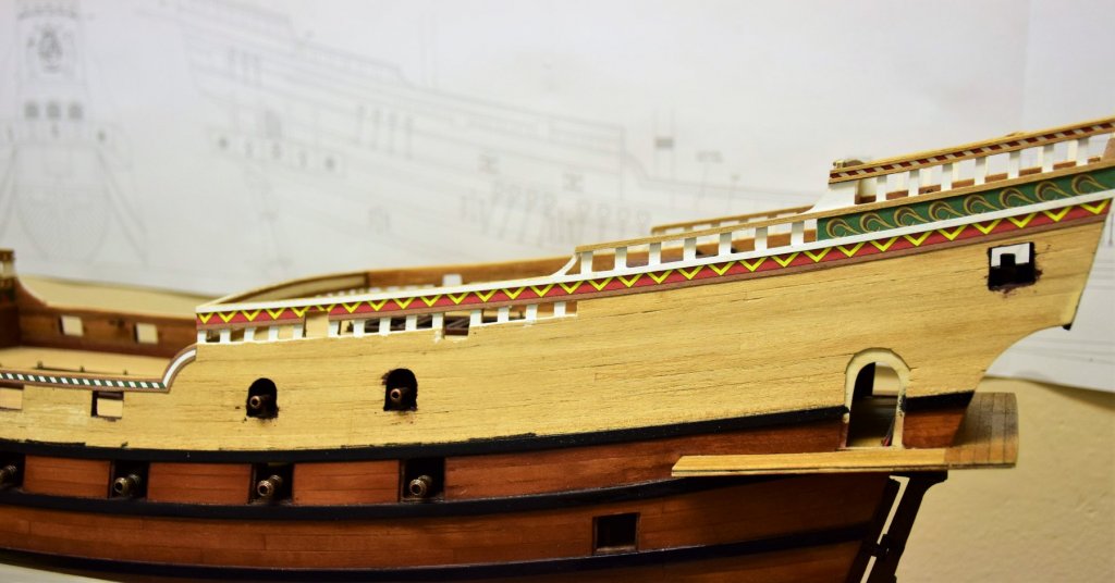
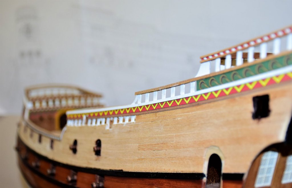
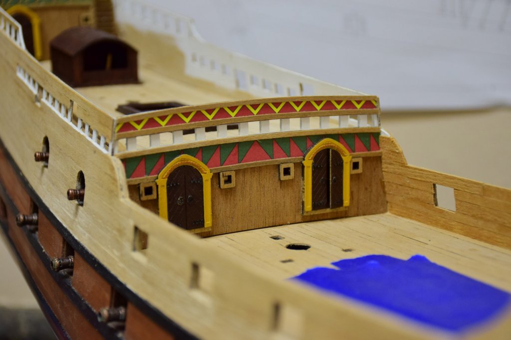
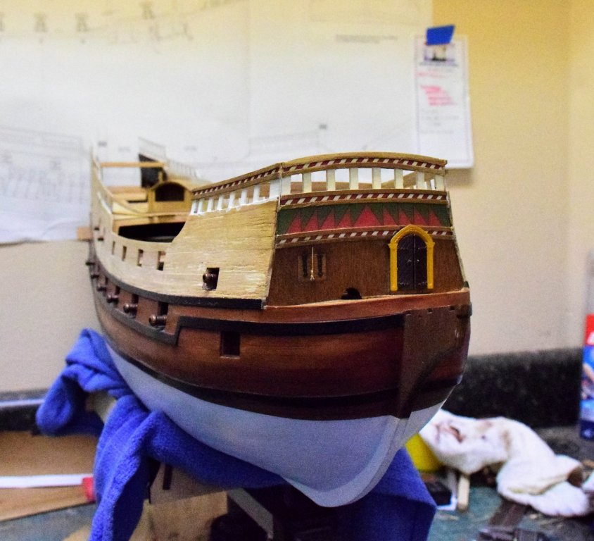
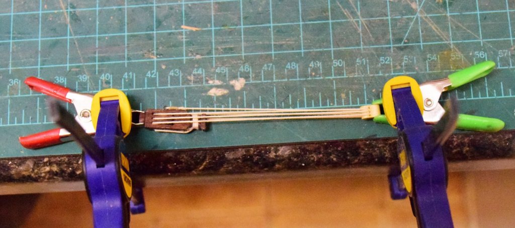
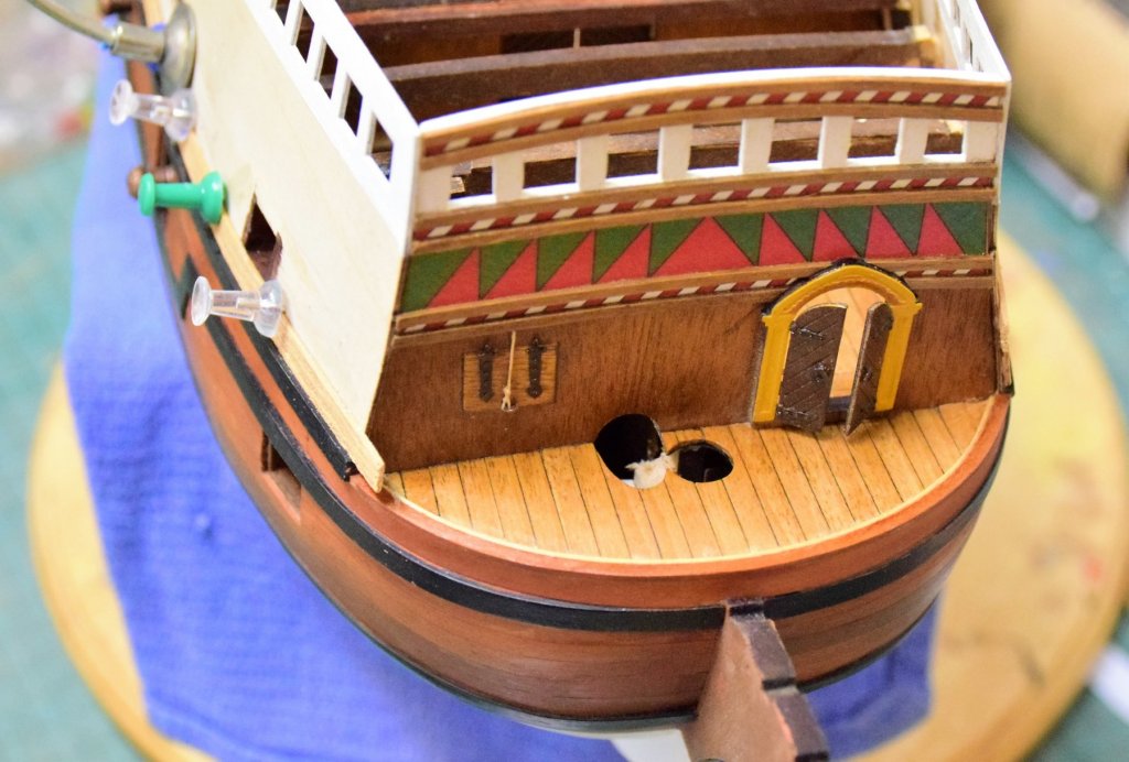
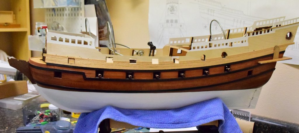
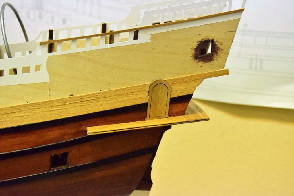
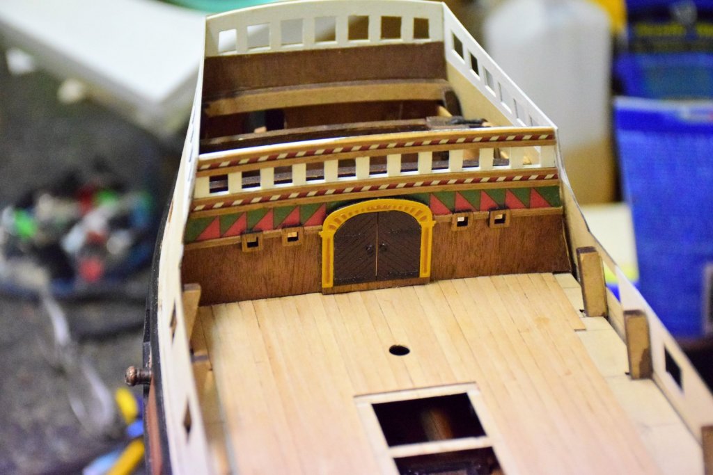
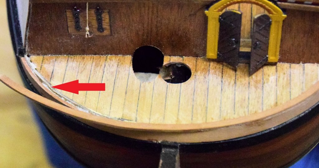
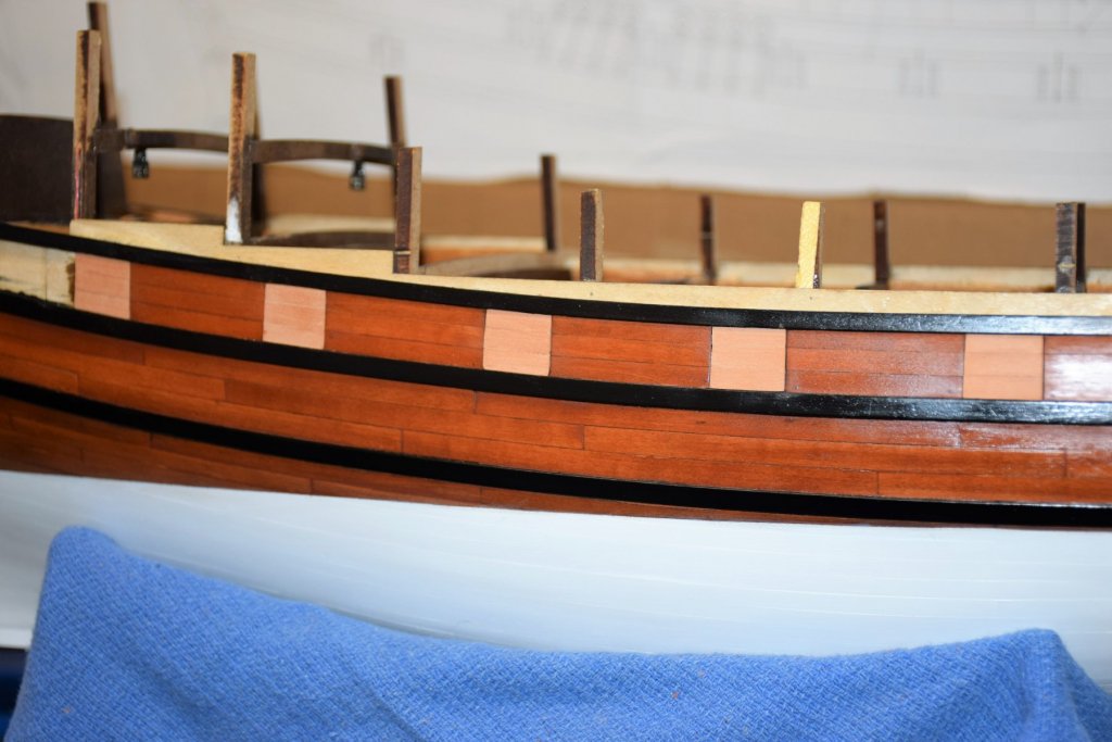
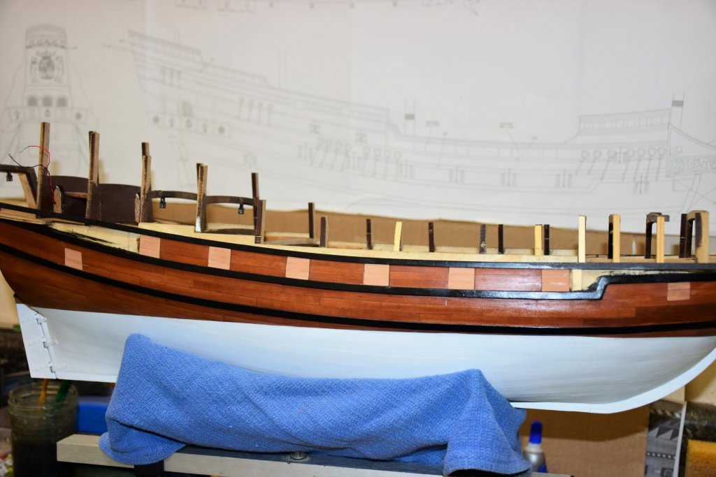
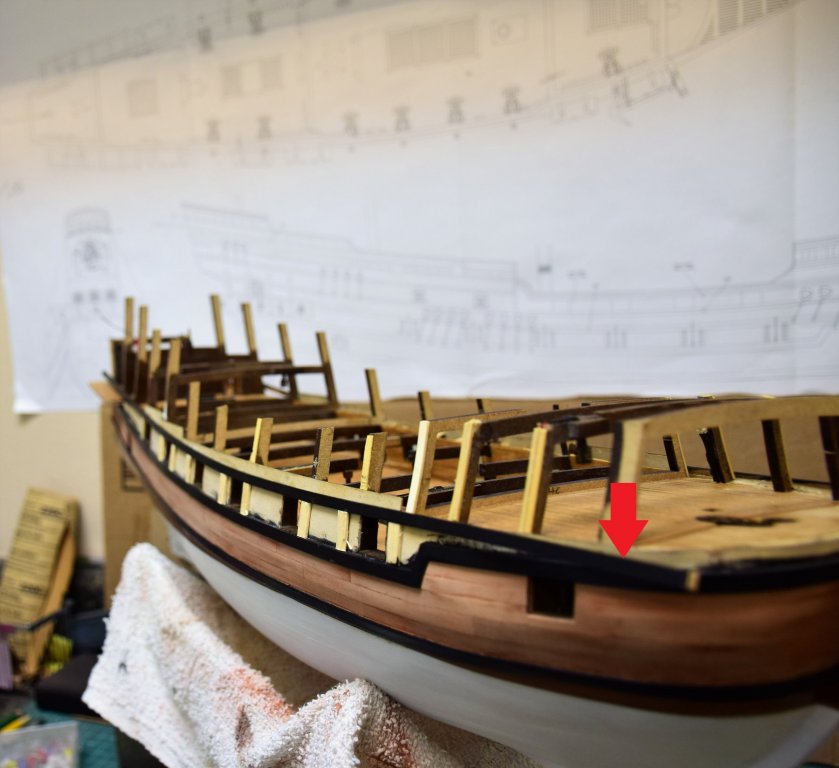
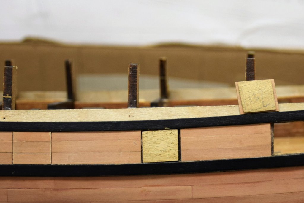
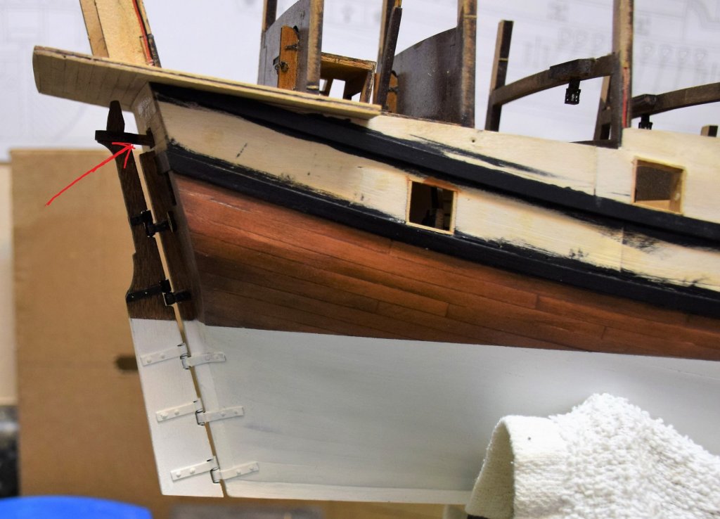
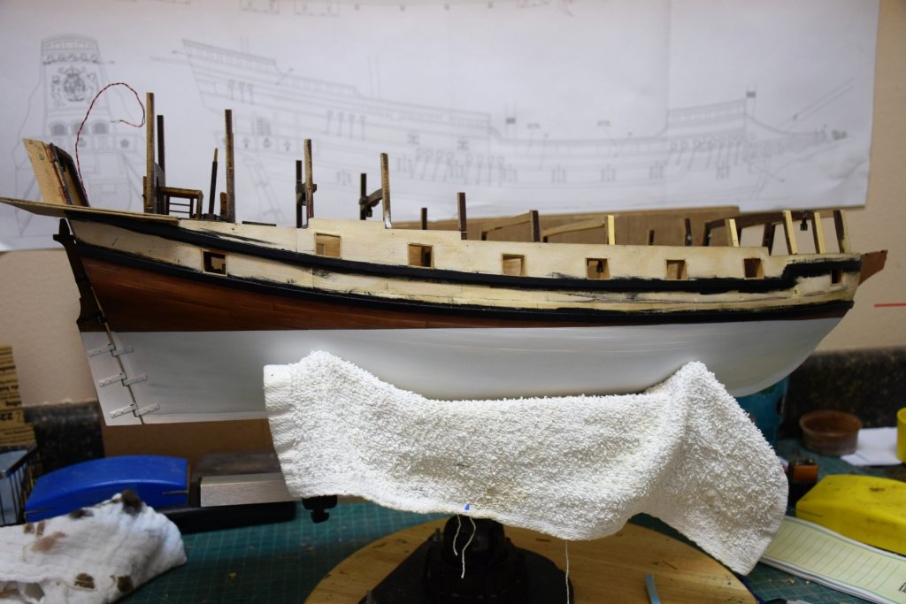
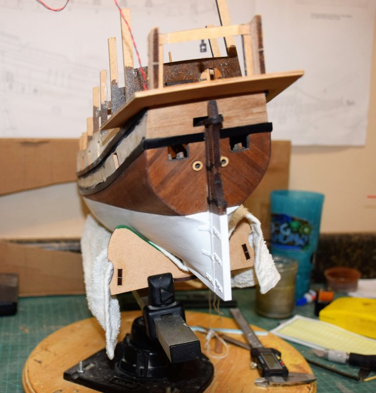
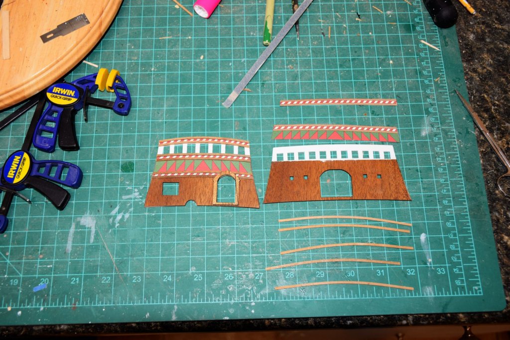
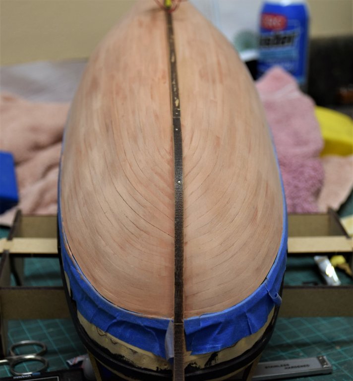
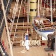 Greetings Work on the side decorations is now complete. All of the decorative strips were placed prior to placement of the wales that separate the various patterns. The patterns need to be trimmed around the gunports (untrimmed area can be seen above). The wale that goes just above the red / white diamond pattern runs almost the entire length of the ship. After staining, the plank was soaked in water and then pinned to the plan profile to help shape it (photo below) This last pic shows to quarter gallery door frame glued in place. I was not quite happy with the trimming of the paper decoration around the curve of the door (arrow in pic above). How I dealt with this will be shown in the next update showing the completed wales. jeff


-
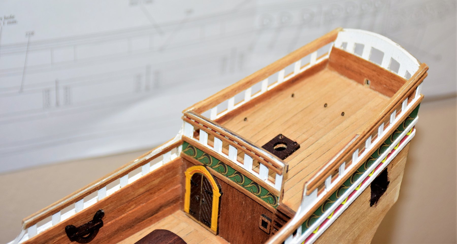
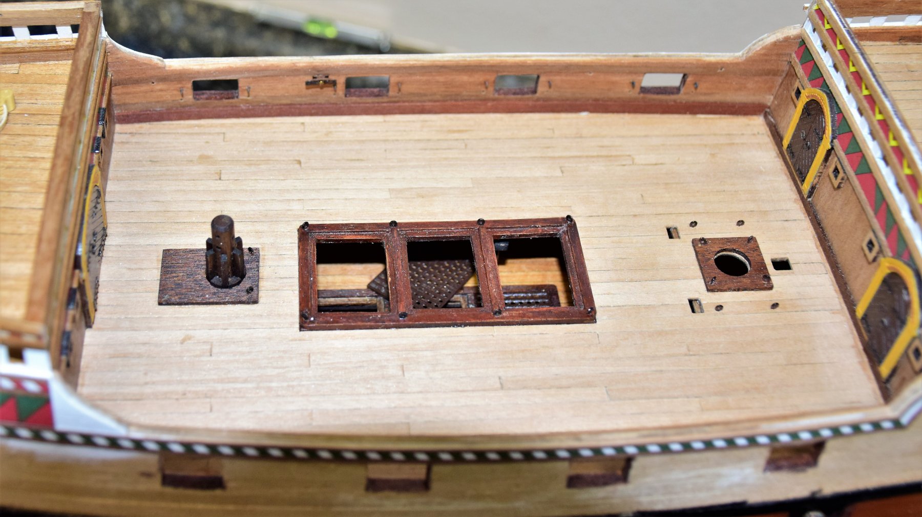
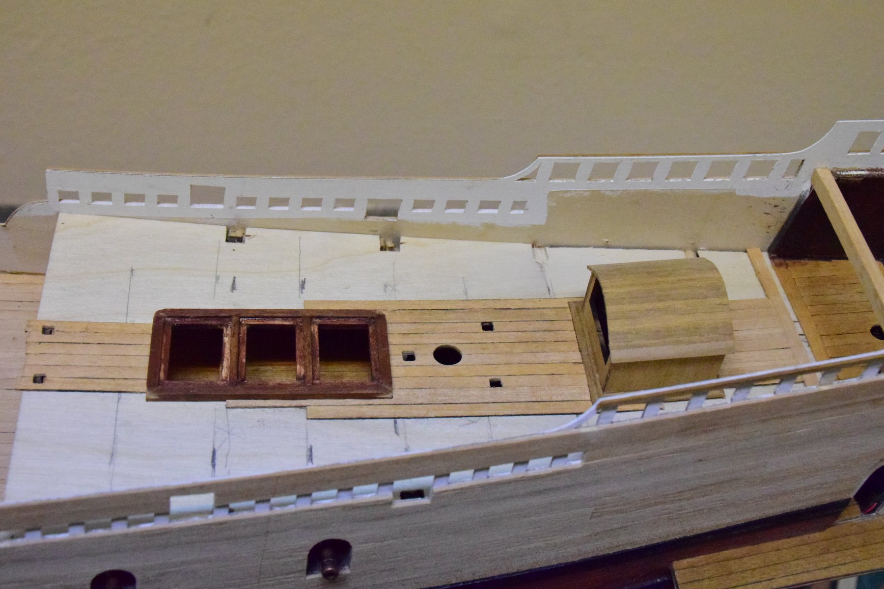
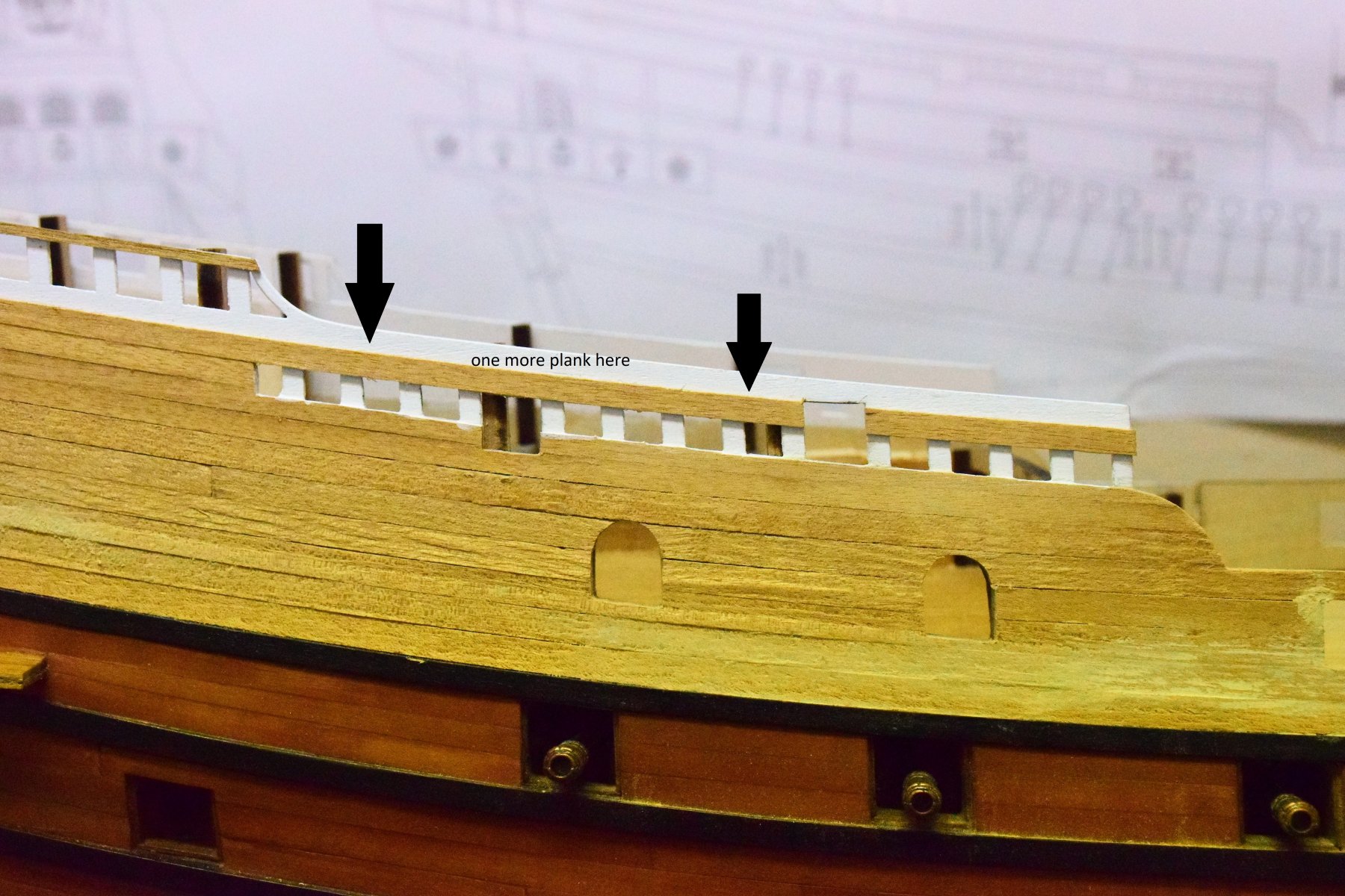
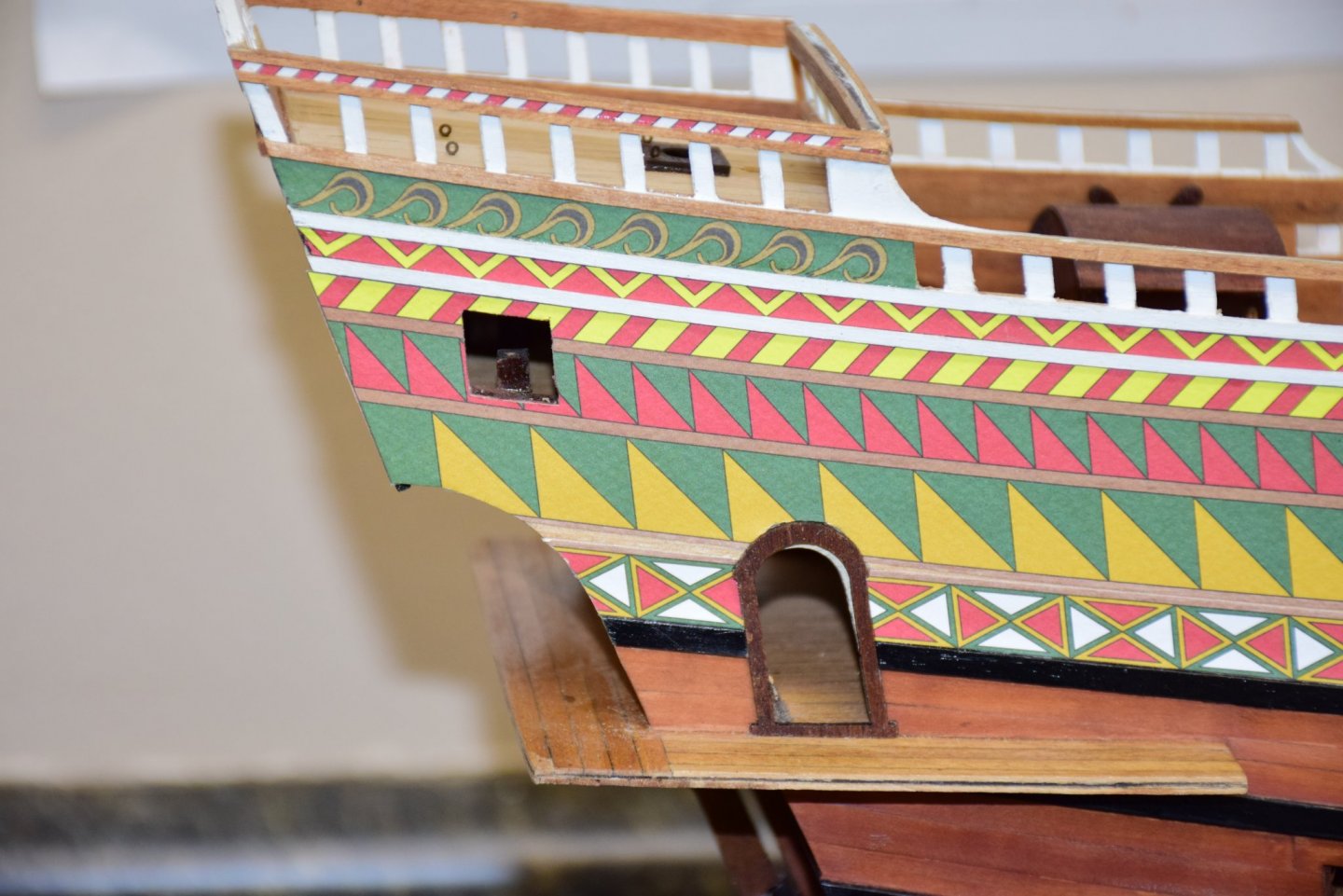
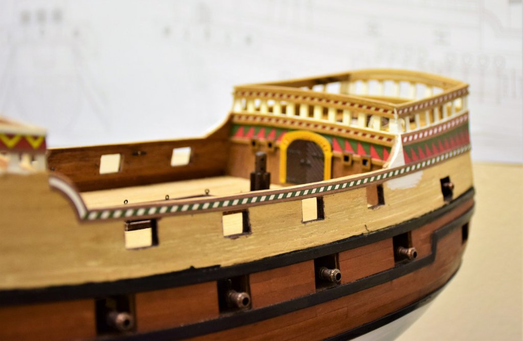
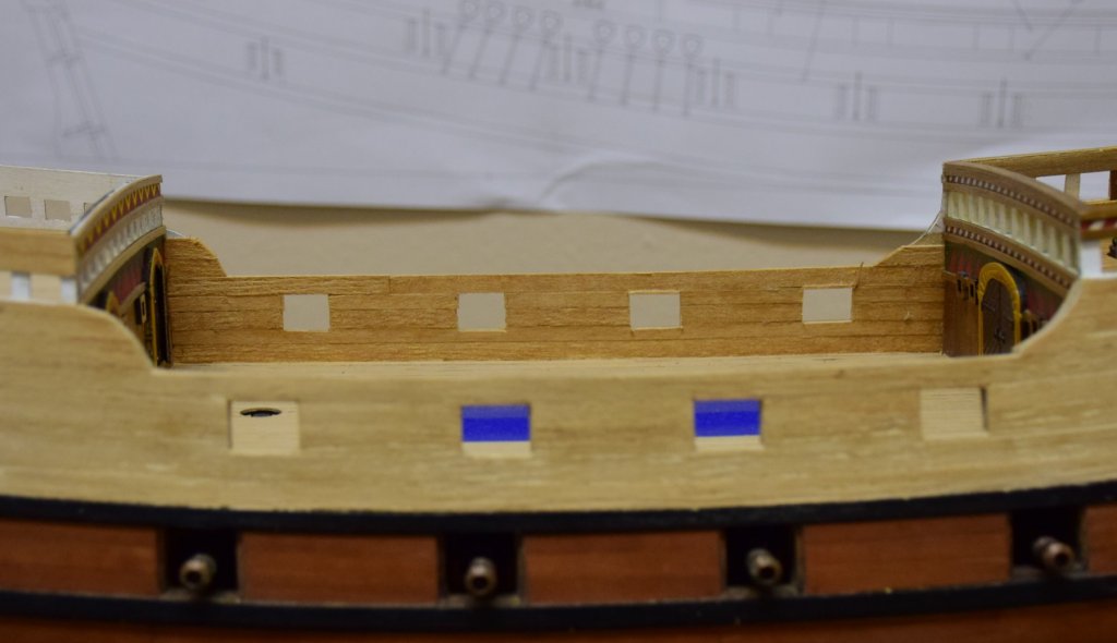
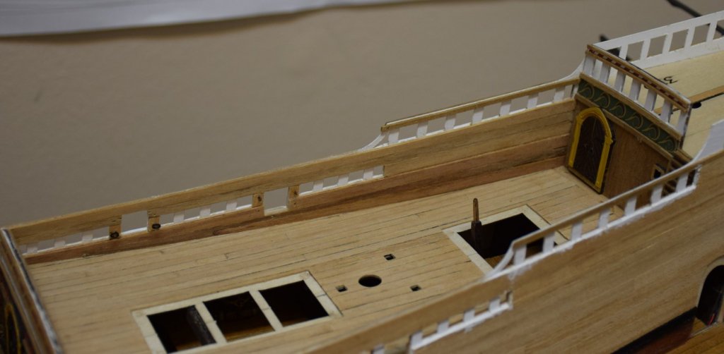
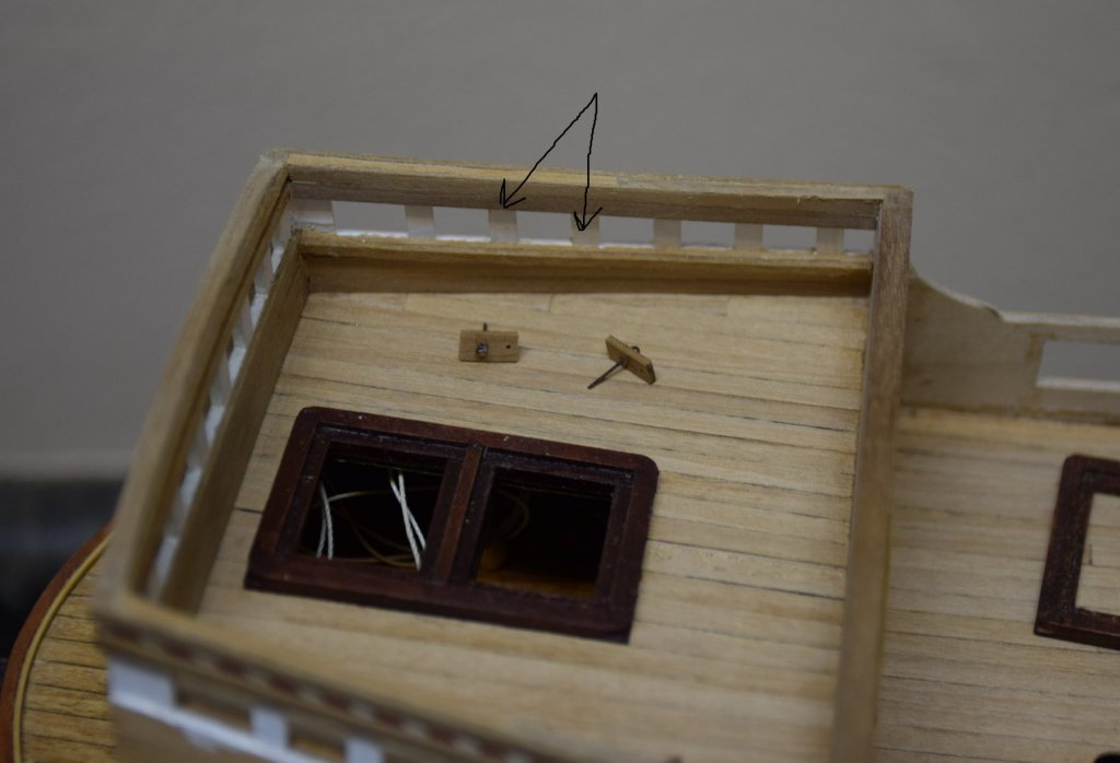
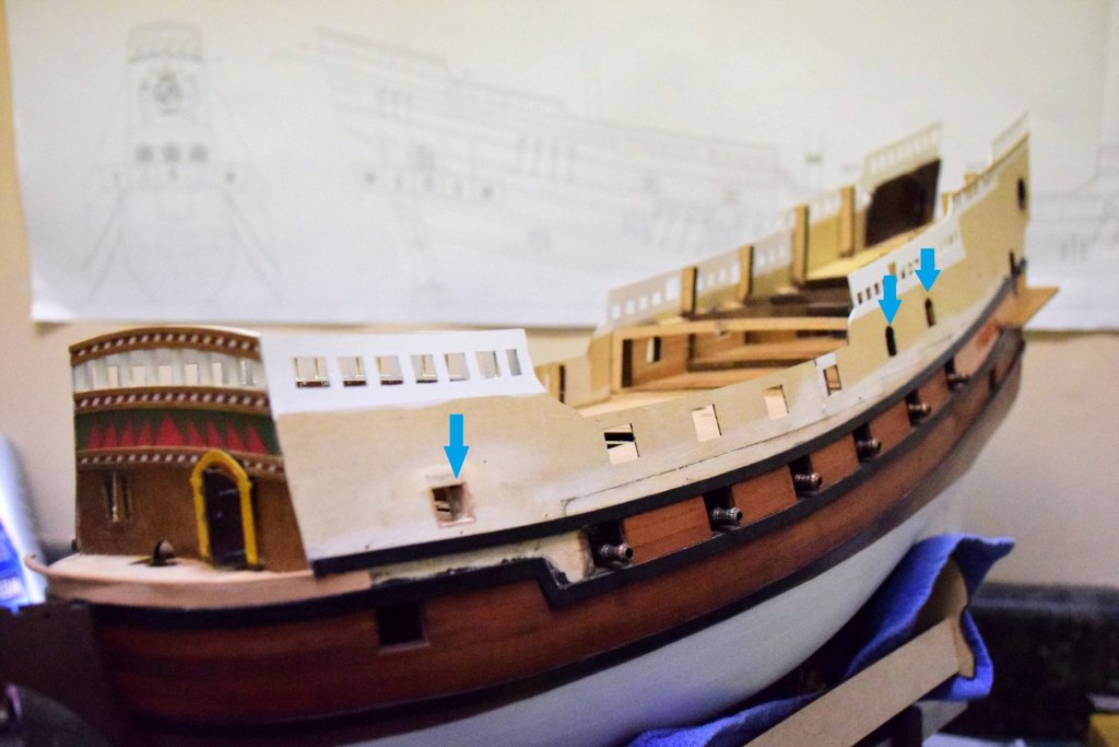
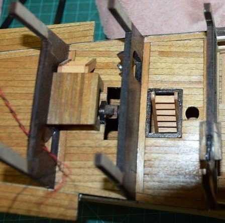
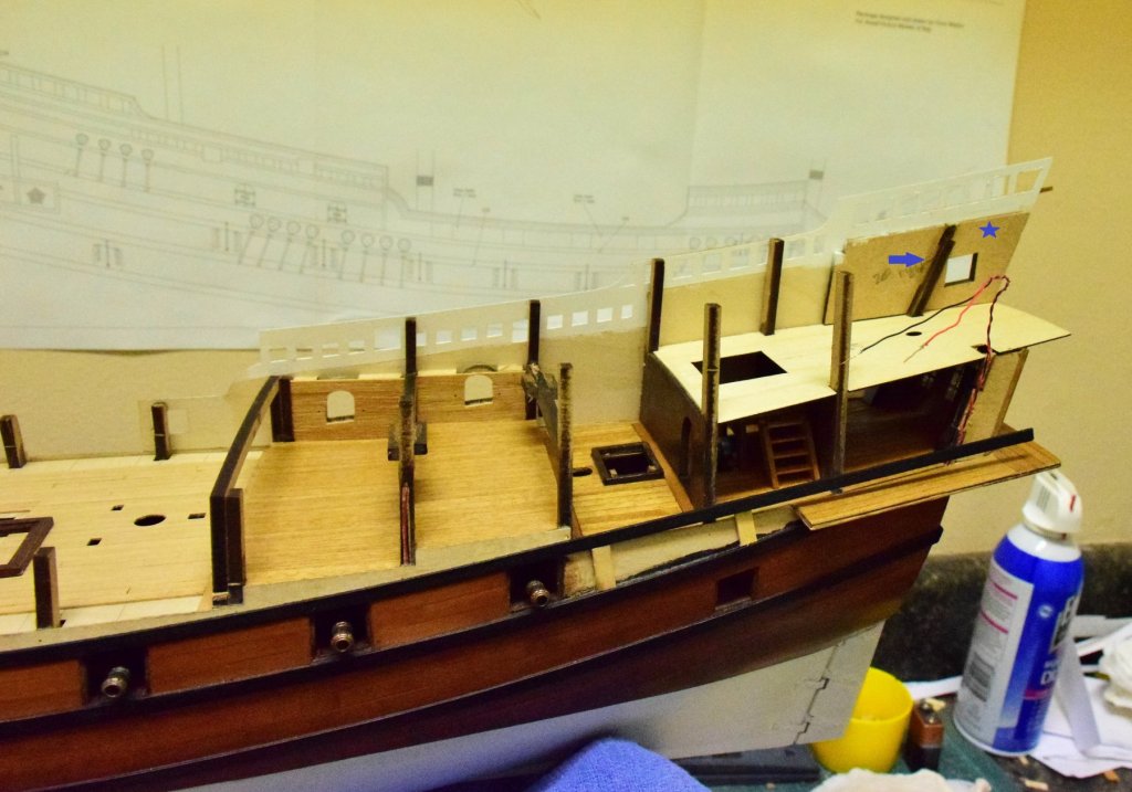
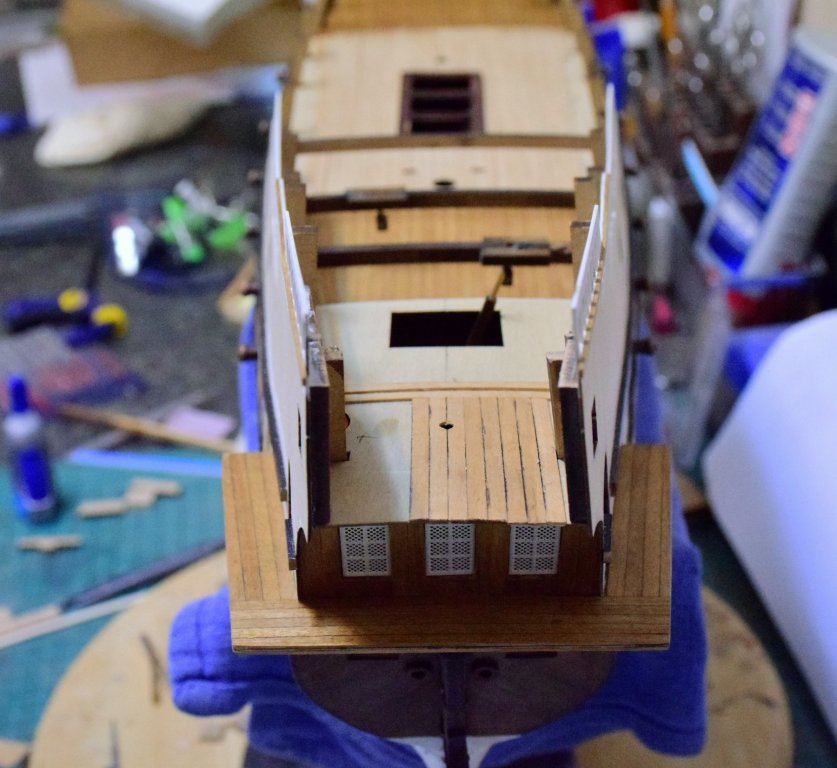
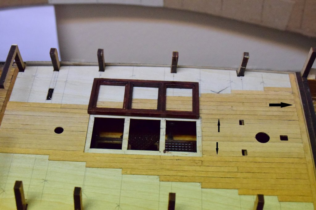
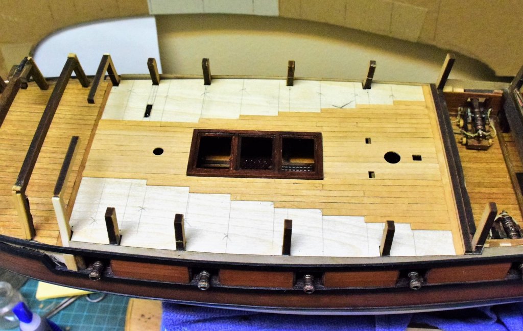
Greetings. Back at the shipyard after vacation biking in Austria and Slovenia. Poop deck is now planked and some of the deck fittings have been place (eyebolts and the mast base). A hole was created at the stern for the bonaventure sail outrigger. On the quarterdeck, the hatch combing and mast coat (orange arrow) have been fixed as well as several eyebolts on one Staghorn clear (blue arrow). I discovered that there are two mast bases for main, mizzen and bonaventure masts. I assume the extra one goes on the deck below (why else would there be 2). I was able to work through the hatches to place the main and mizzen mast bases. The place where thelower Bonaventure base would go is completely inaccessible so...another spare part. Same work done on the main deck. one cleat has been placed as well as some of the eyebolts that will be used for the cannon rigging. Now onto placement of the paper side decorations. This is one area where there is no tolerance for error and once they are glued there will be no way to remove them. Also, there are many parts that have to be glued to the inner bulwarks (belaying pin racks, cleats and staghorn cleats). Instructions call for drilling a hole for a pin in these parts to add stability when on the model. Of course that means drilling a hole in the bulwark which will invariably go all the way through. So, all of these parts were pinned and a corresponding hole was drilled into the bulwark before placing any of the paper decorations. Each part was then place to be sure the pin was not too long or else it will still pierce the paper when placed. Some of the printed decorations in place...aft … and forward. The black arrow on the photo below shows the brown stripe on the printed decoration where a 1x2 mm plank will go. Jeff


-
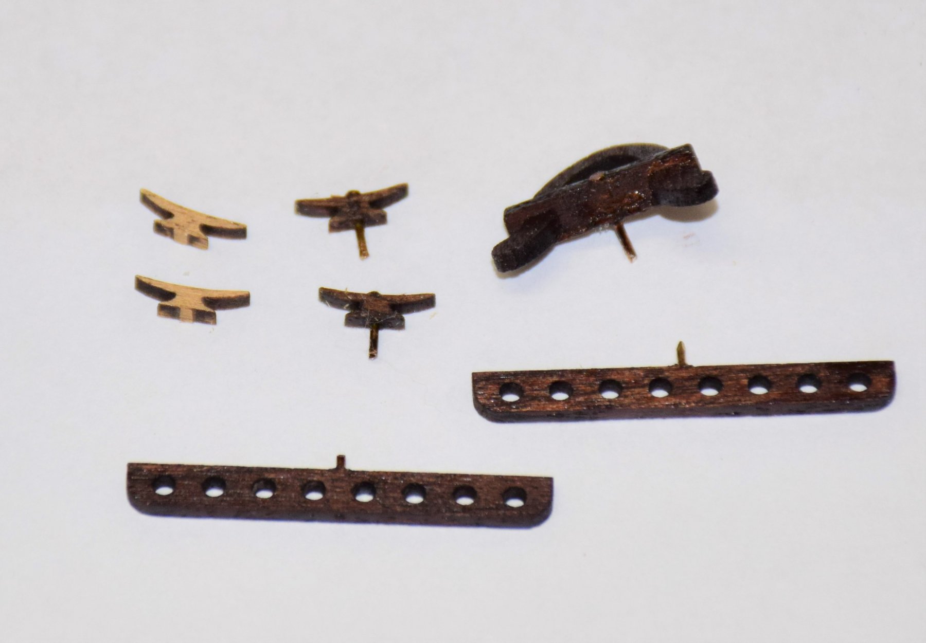
Thanks. I am sure there are several other pre shaped kit pieces that will be discarded. I think this kit would be even better if Amati changed from dibetou to some other type of wood Jeff
-
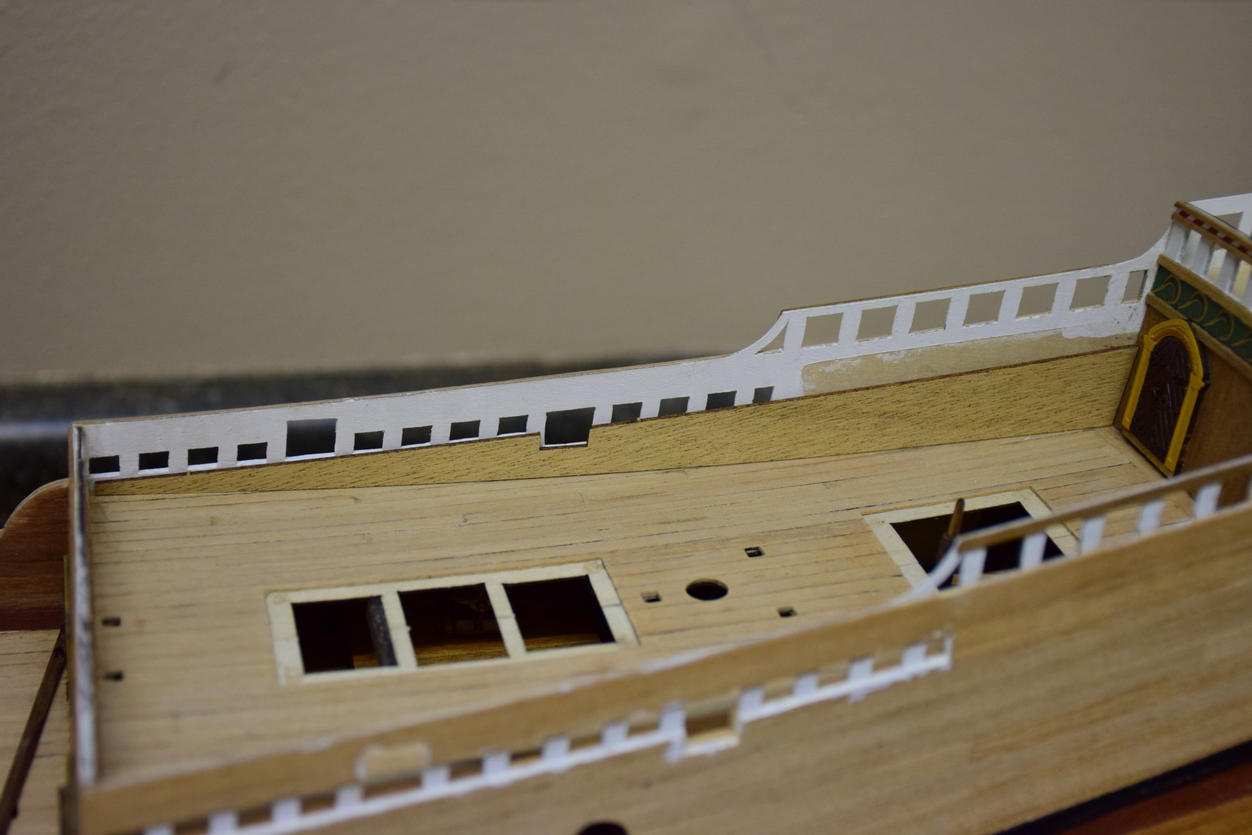
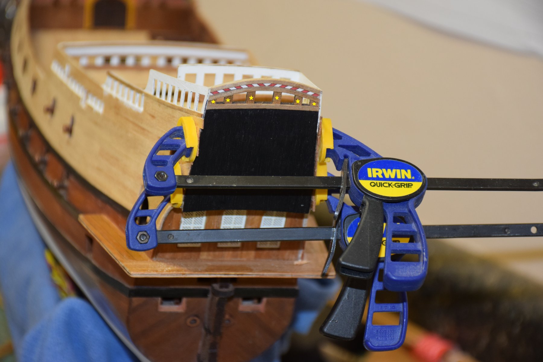
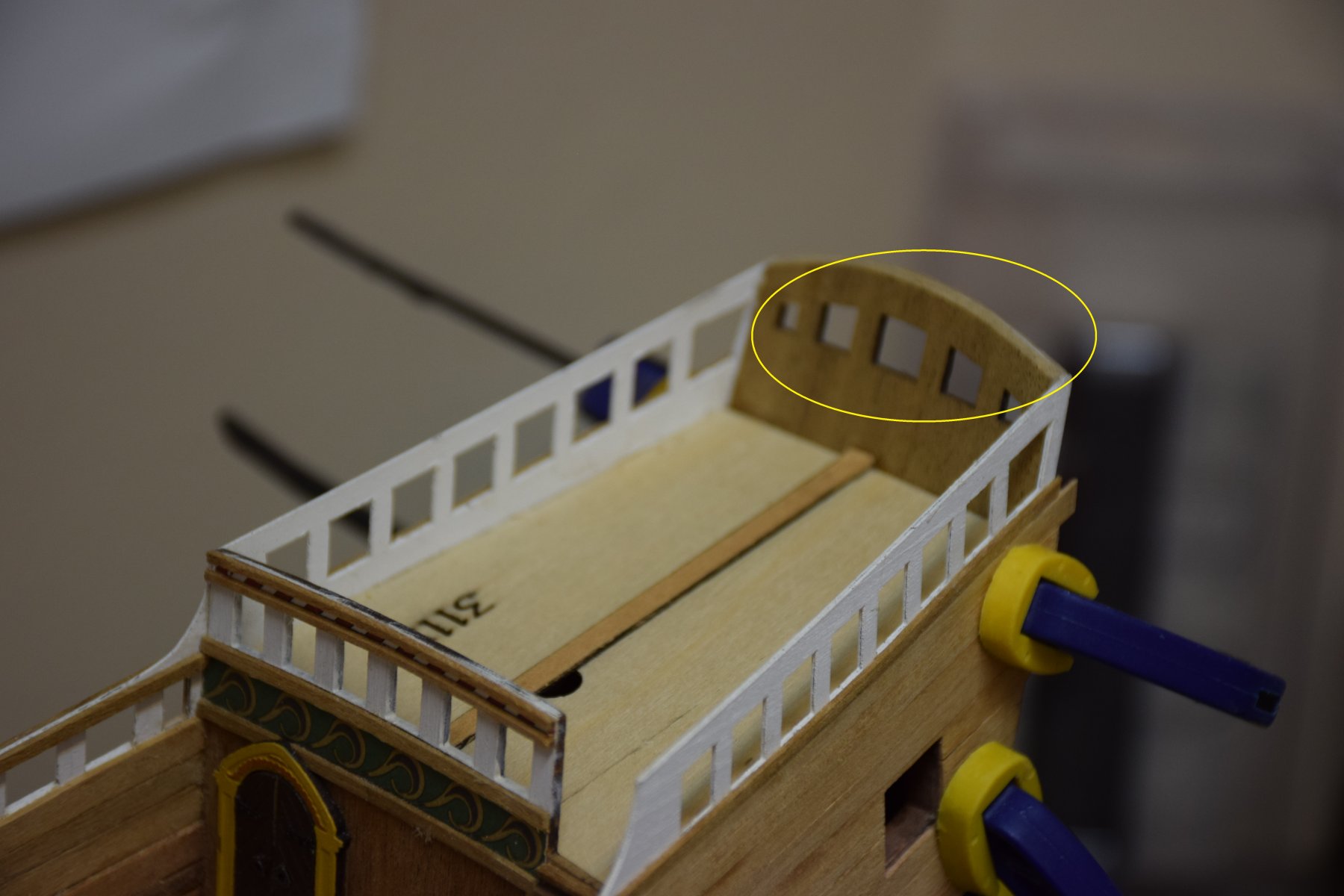
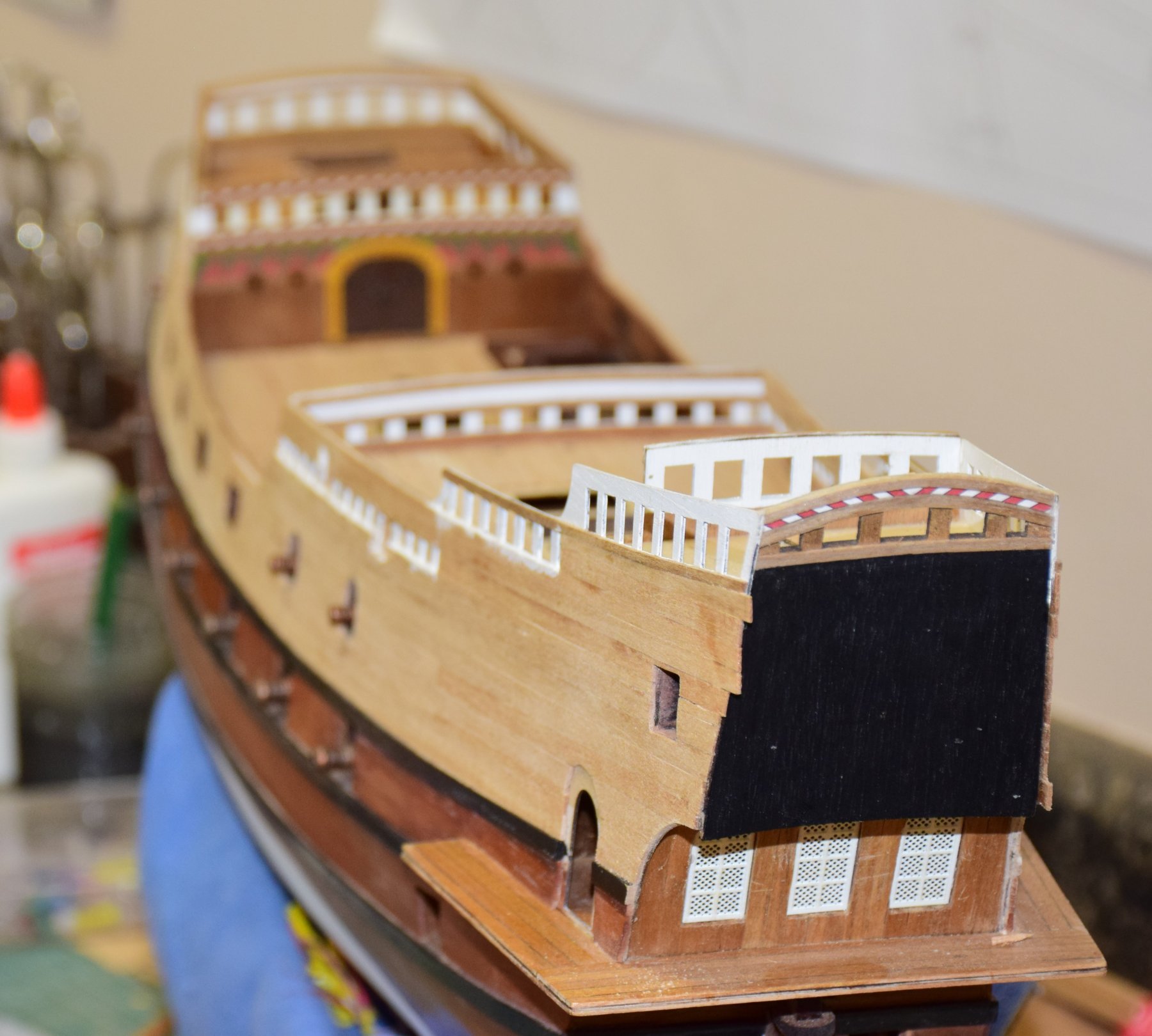
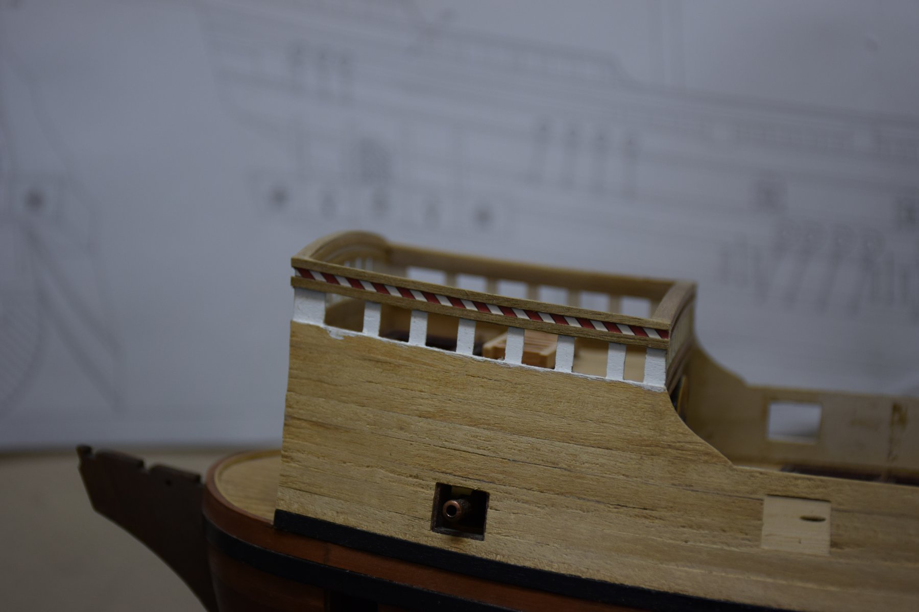
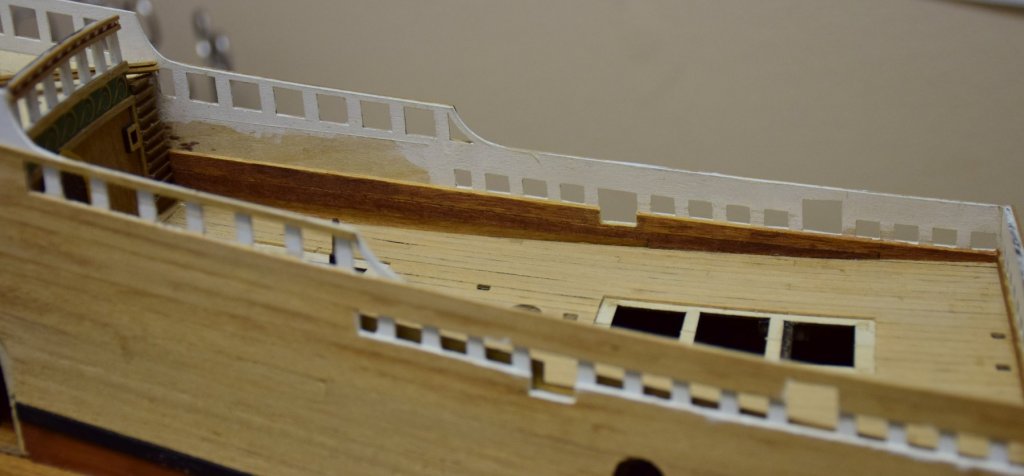
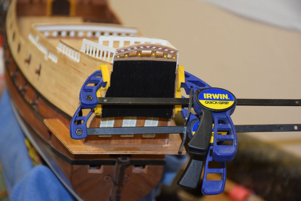
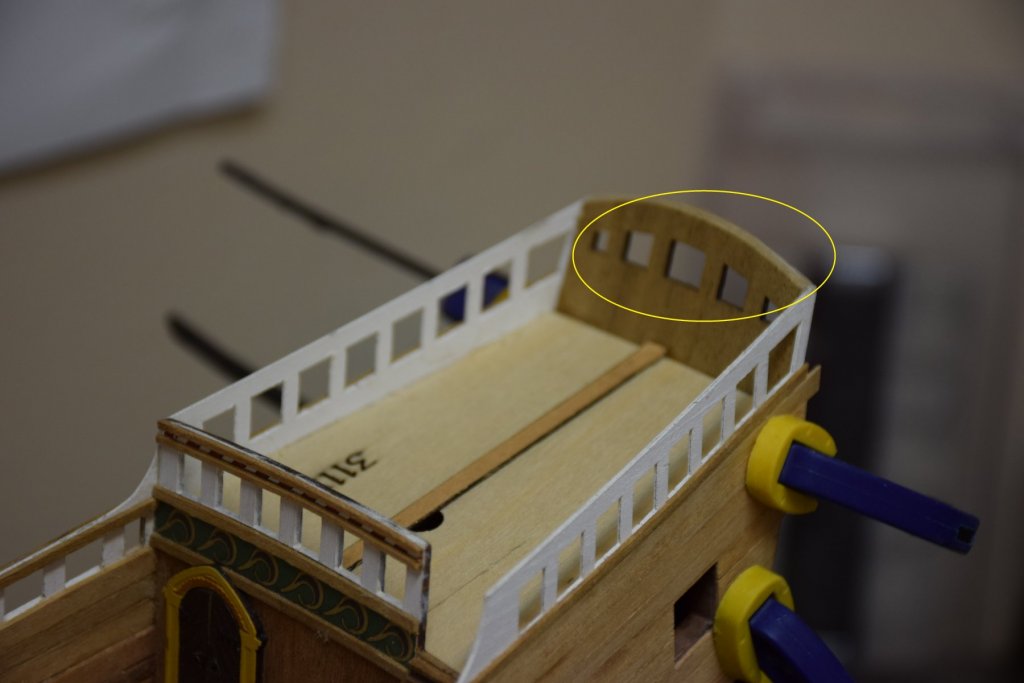
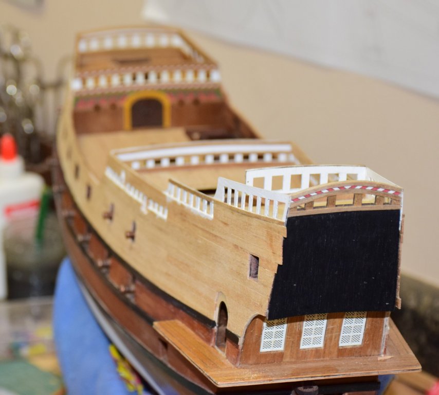
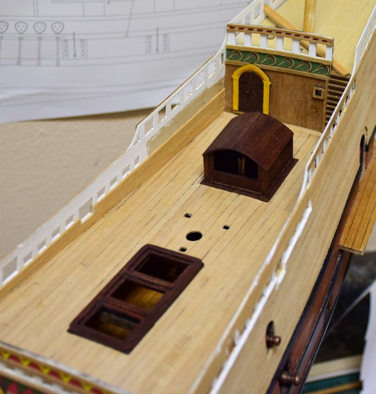
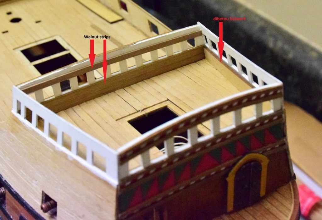
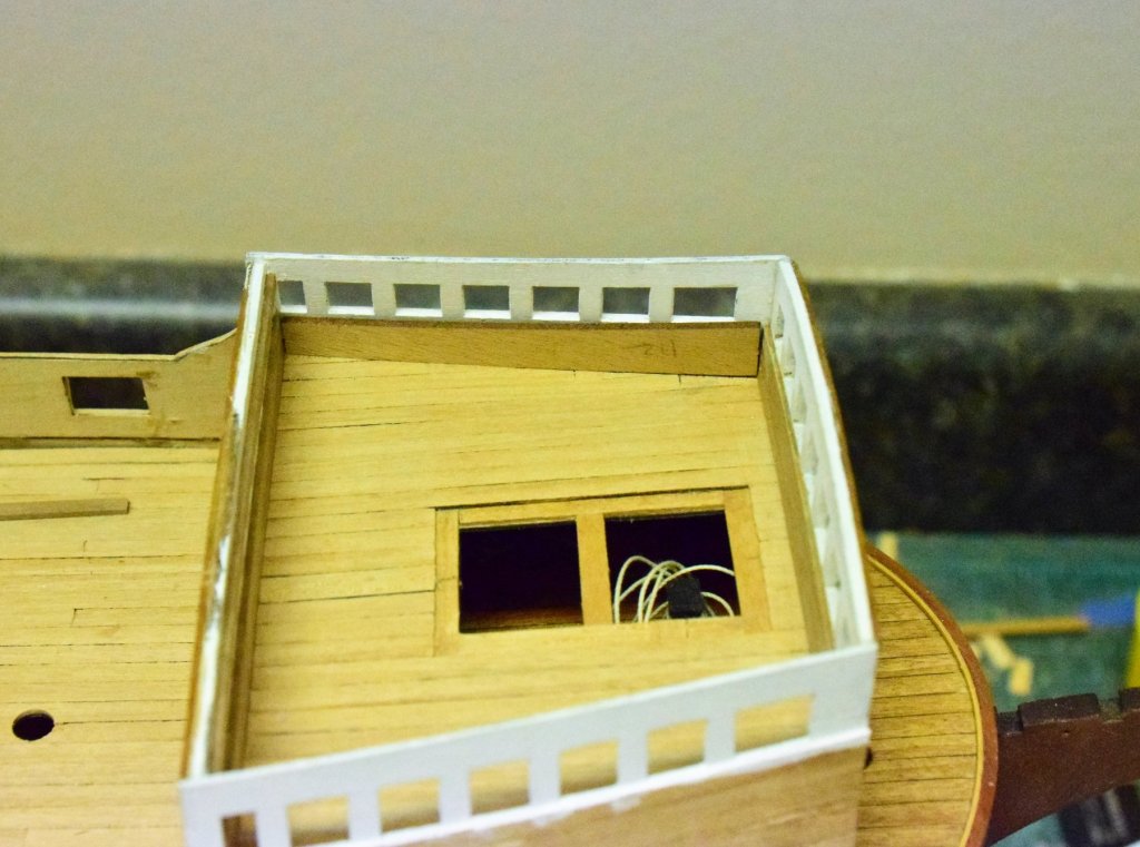
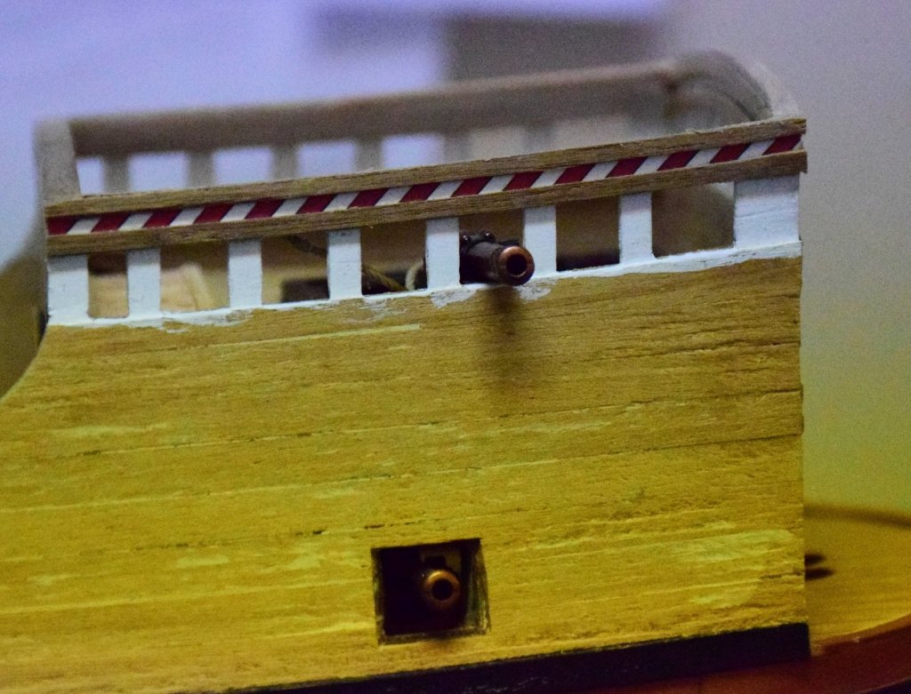
Greetings The bulwarks for the upper deck are supplied precut using 2 mm dibetou wood. if you have been following this log, you already know my opinion on this wood so...not having any 2 mm planks I decided to double plank - the inner layer were planks left over from the hull planking - 1x5 mm. here's a pic of one side with the first layer mostly complete. The second layer was a combo of 1x4 and 1x5 mm walnut left over from other kits. some holes and ringbolts also visible for the cannon rigging. A separate 5mm plank is placed long the bottom of the bulwark (therefore 3 layers here). photo below shows the kit supplied dibetou piece (cut in half). this piece would have required quite a bit of modification to get everything to match up. one can see the coarse grain and the arrow shows how one small area broke off. this was the problem I had with the prow - if you look back at prior posts, one can see that the prow is missing. Even though this is 5 mm dibetou, one misadventure in turning the ship and snap, off it came along the grain. one useful modification for this kit would be to have the stem as a separate piece to be added at a later stage Quarter deck bulwark has the same pre shaped piece. They are now in the trash. Quarter deck was planked the same as described above. In the photo below, the area below the cutouts is double planked (therefore 2 mm thick). The area above this is single layer, 1 mm walnut bulwark planking complete and, the last deck to be placed is the poop deck. This deck comes pre shaped, 2mm thick. This is the only deck at this thickness. I decided to discard this one and use scraps from the other deck pallets. 2 pieces glued together and then cut to the correct shape. this deck is glued in place at the same time as the upper stern board (basically the back of the ship). The upper decorative strip (paper) and 2 1x2 mm walnut strips were placed prior to fastening this piece to the ship. It was at this time I realized the upper part needed to be white like the bulwarks (no mention is made of painting this area in the instructions - the picture does show the slats are white so I guess I need to pay more attention) . Yellow stars should be white in pic below Area in oval should be white in pic below. Not very hard to do but it would have been much easier while still off the ship. And lastly, the stern board in place. The side planking needs to be sanded flush and poop deck planked. Everything coming together quite nicely so far Jeff


-
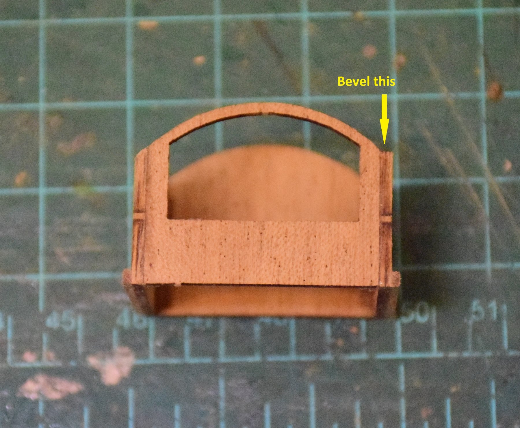
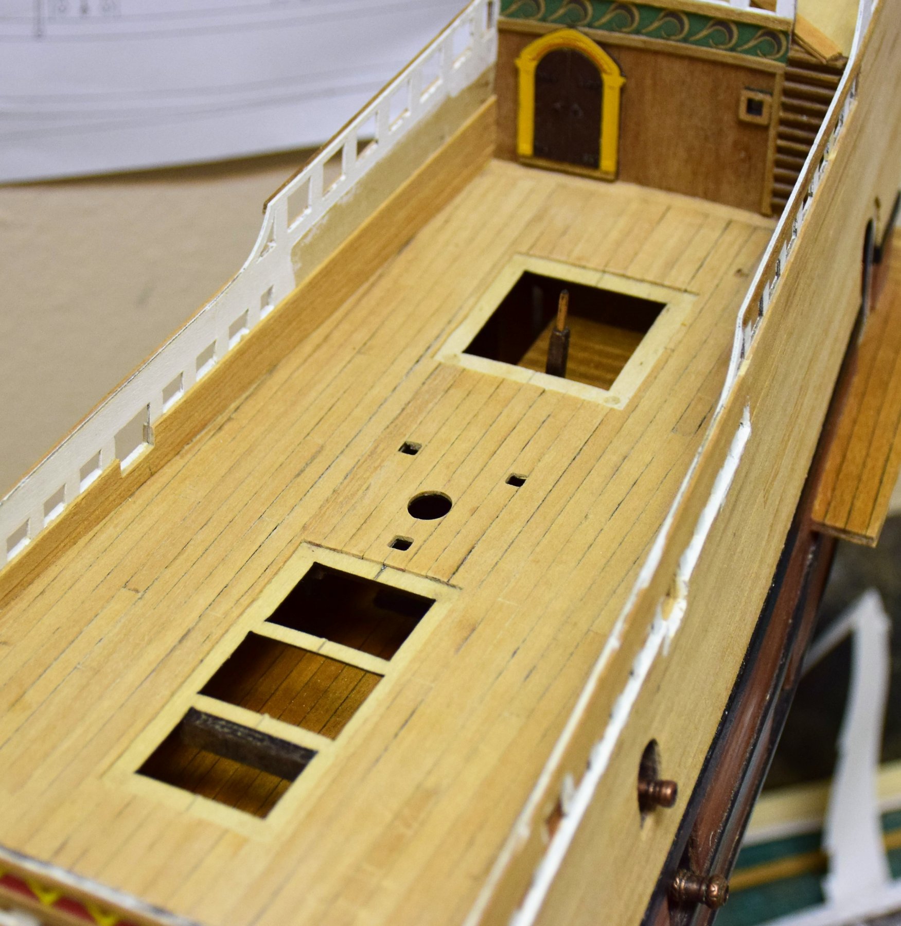
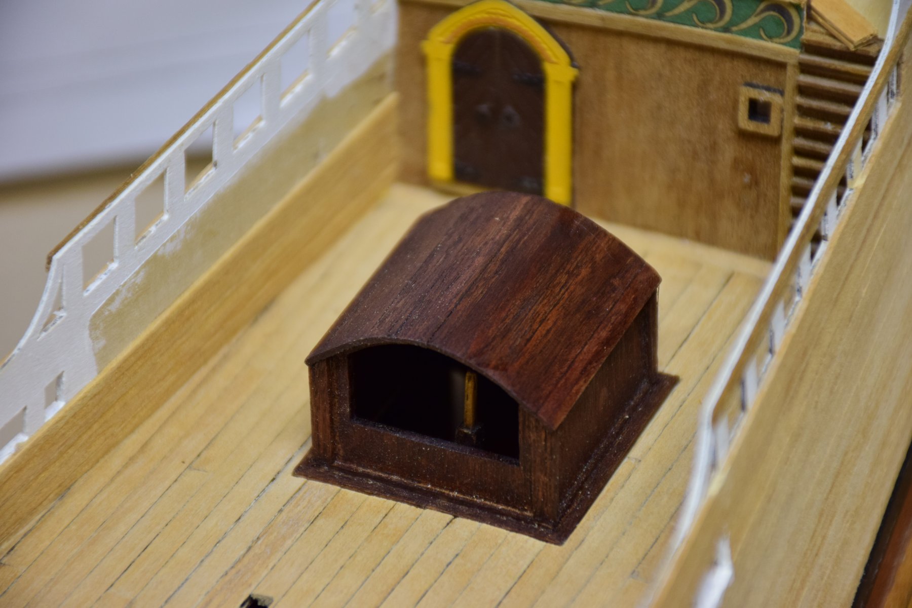
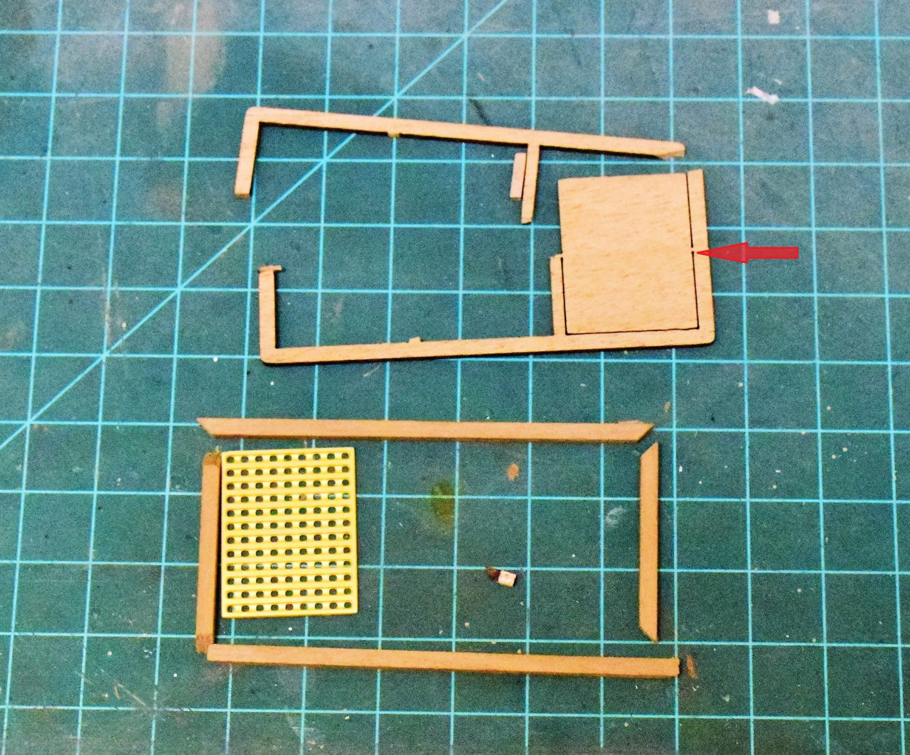
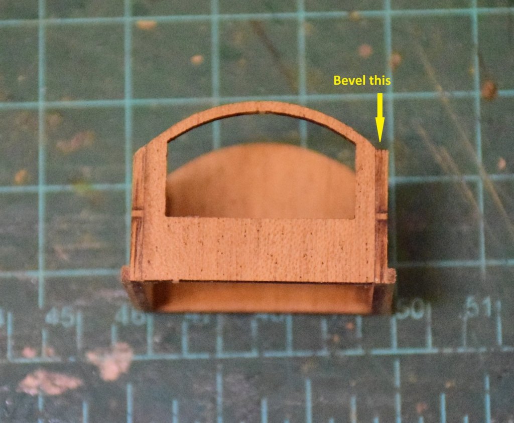
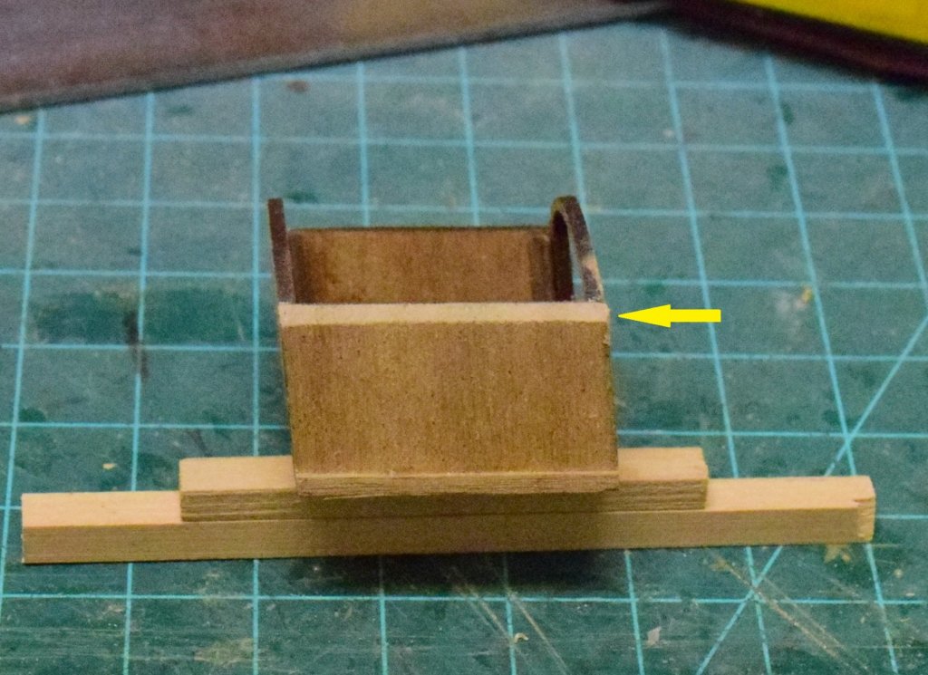
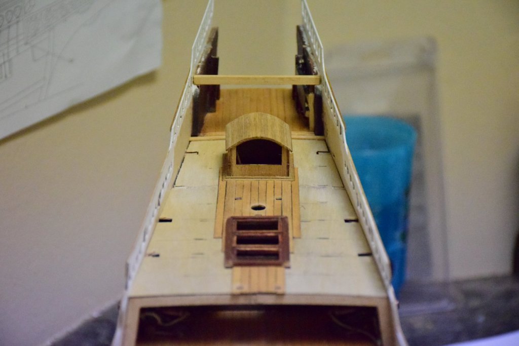
Rather than fitting out the forecastle, I decided to move on to the quarterdeck. While planking the deck, the helmsman's canopy was constructed. This comes as 4 parts for the walls and 1x2 walnut for the roof. the upper ends of the side walls need to be beveled to accommodate the roof planks (arrow in pic 1 and 2) Quarterdeck partially planked. Planking was placed to leave a recess for the hatch combing and the helmsman's canopy. Quarter deck now planked. Here are views of the deck with and without the hatch combings and canopy. Too bad all the work that went into the lower decks is now not visible. once the deck is complete the aft 2 bulkheads can be glued in place. The aft most one can be seen in the photos above. The other can be seen below Make sure all the edges line up or there will be problems when the rails get placed (see arrow below) Next up are the bulwarks for the main and quarterdeck. Jeff


-
Greetings Past few weeks spent finishing the aft 2 bulkheads, placement of the forecastle upper deck and quarterdeck and finishing the forecastle. first was the deck planking. there are 2 of the smaller cannon located on this deck and I found that they sat a bit low , even after accounting for the 1 mm planking. easy solution was to install a 1 mm sub planking. a cutout in the planking was made to accommodate the grating. The fore and aft bulkheads are planked with walnut strip; the kit has a precut piece for the bulwark plank but this was dibetou and I did not like the look so I used walnut for this too. The bulwarks and inner bulkheads now planked. 2 more 1x4 mm small strips need to be placed which will hold the eyebolts for the cannon rigging. the eyebolts were place first then the strips will be glued in place (arrows). I the holes are drilled after the strips are placed, you may risk drilling too deep and piercing the outside of the bulwark. The outer upper decorative strip with the 1x2 mm borders were also placed in order to be sure the inner bulwark planking was even with the outer Forecastle cannon with breeching rope, testing fit... I will finish up this area with the ladder to the lower deck and the fittings (pin rails, cleats and eyebolts then move on to quarter deck Jeff


-
Filler Blocks
xodar461 replied to olopa67's topic in Building, Framing, Planking and plating a ships hull and deck
At the bow I filled in the front 4 spaces between the frames with basswood (a variety of sizes as you can see from the pic on my log - page 1). I felt this would be easier than trying to shape one bigger block. I then used a dremel with a sanding drum to rough it out and finished with manual sanding. I think the stern only needs the aft most space filled as the curves here are much more gentle than at the bow. Basswood is fairly soft and very easy to work with. It will also hold small brass nails. I bought a pack of strips, multiple sizes at a hobby store. you can find blocks of basswood on amazon too. Jeff -
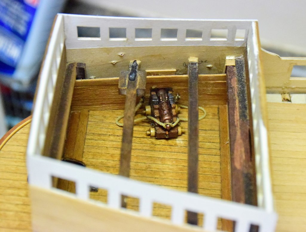
greetings with the external hull planking now complete, time to return to some internal work. there are 3 cannons left that are below deck. These were rigged with the breeching tackle and then glued to the deck external view of the cannon that were just placed One VERY important step is to place the forward knighthead. this goes into a small slot on the forward lower deck. however, if the knighthead is placed without rigging it beforehand, it will be almost impossible to rig it when the upper deck is in place (you would have to do it through the rather small hatch opening). Review of other Revenge logs show what can happen if this step is not done. so, referring to the rigging plans, the knighthead was rigged off the model with the appropriate ramshead block., then glued in place. when the upper deck is in place, the rigged block can be easily retrieved. Next up will be to complete the aft 2 bulkheads and complete the remaining decks. jeff


-
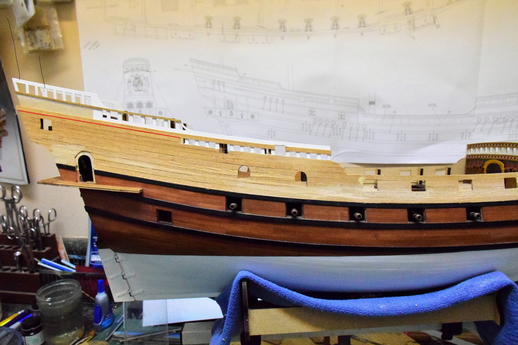
Hi. new progress report. Below is a photo of the bow deck, now completed with the addition of the pear strip and a 1x1 mm boxwood strip. With the 2 upper side patterns now in place, it is time to plank them. I decided to use full length strips of the wood supplied with the kit (1x5 tanganyca)as a time saving technique as any butt joints will be covered by the colored paper patterns. Not very impressed with this wood but this area will all be covered so no need to use something more expensive. The side gallery door frame was temporarily placed to help guide the run of the planks. Planking at the bow is complete. Some wood filler added to fill some minor gaps. Stern is almost complete. Instructions call for the planking to stop at the red line on the pic below.. However there are several wood strips 1x2 mm that are placed to separate the printed decorations. If the planking stopped at the red line then the 1x2 strip that goes here would be flush with the 1 mm planking that stops here. Photos in the manual show that this strip is not flush, I decide to continue the planking up to the 1x2 strip already planked aft Starboard side complete. After some sanding, side patterns will be ready to go on. Or I may complete the deck work and 3 cannons that are still to go below deck.


-
Thanks for the great comments. Re: the "painted" areas, these are actually printed on paper and are simply cut out and glued to the correct area. Only one copy given so no going back once they are glued - get it right the first time. Attempting to paint these areas would be very tedious and I am not sure the result be be as good for most people. To Vulcanbomber, i agree it is satisfying to figure out ways to fix / improve the kit. Some parts of the construction are more like a puzzle that have to be solved before moving onto the next stage. I am always looking ahead in the construction manual to see if I can find a better way to build the ship. The manual is more like a general guideline in building the model for me. BTW i love your cross stich project. very unique Jeff
-
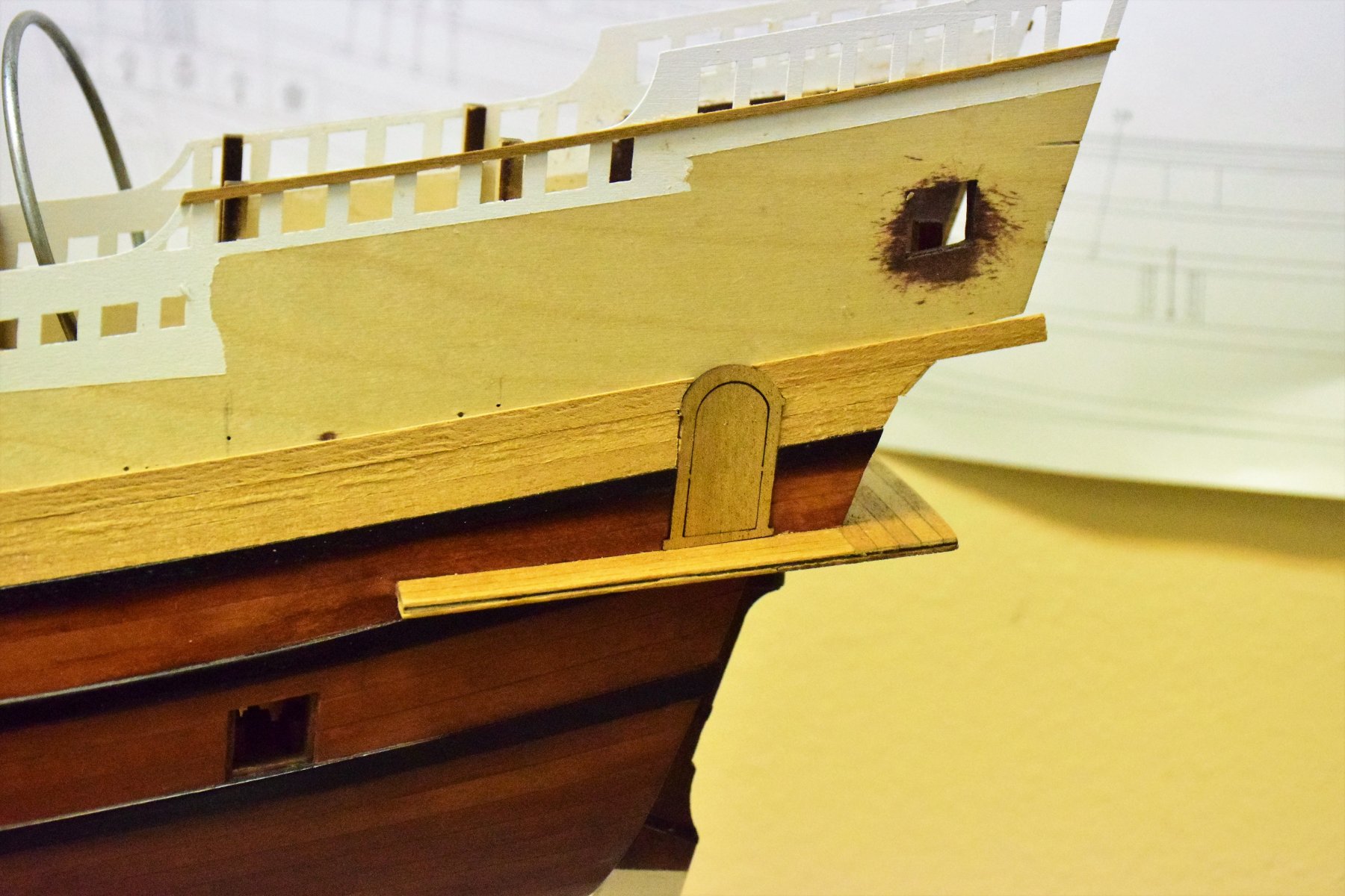
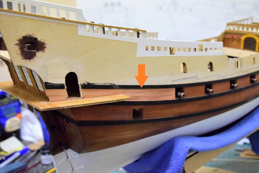
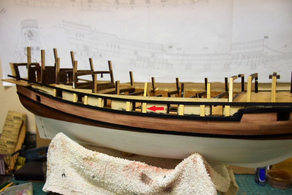
Salut! The forward side patterns are now on and I am working on finishing the planking between the wales. Both forward bulkheads had to be finished and placed on the model before the side patterns as they would have been difficult to fit after given the curves of this area (pics 2,3). Note that the aft 2 bulkheads have not been placed. test fitting showed that there will be no problem to fit them after the aft pattern has been placed. My goal is to have the exterior planking done so I can fit the last 3 guns with tackle that are below deck (pic 1, blue arrows). Below, finishing the aft planking between the wales (orange arrow). The door frame (not seen in this photo) was used to allow the proper placement of the planks. Another way to do it would have been to plank up to the opening and glue the frame to the planks. When laying the plank around the bow, I found that there was not a smooth transition from the forward deck planks to the hull plank. The arrow shows that the lower forward pattern edge is visible - not a good look IMO. So I decided to place a strip of swiss pear 1x2 mm around the curve of the bow for a cleaner look. This required some sanding of the finish from the deck which account for the "unfinished" appearance. A final photo of the area will soon follow. Jeff

-
I would not worry too much if the model does not exactly match the pictures. And I would not move the opening for the ladder. It will just be extra work that is not needed. This area on my model has a 4 mm strip running across the deck aft of the hatch combing. jeff
-
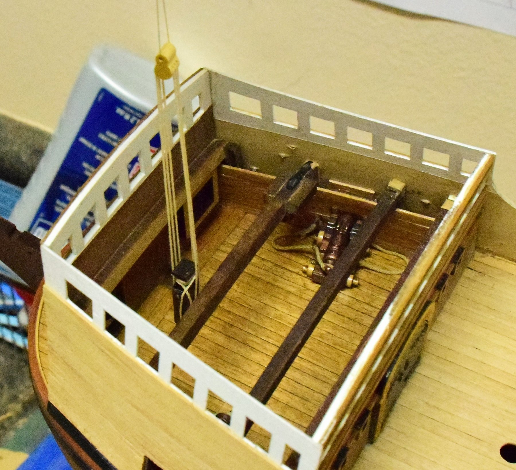
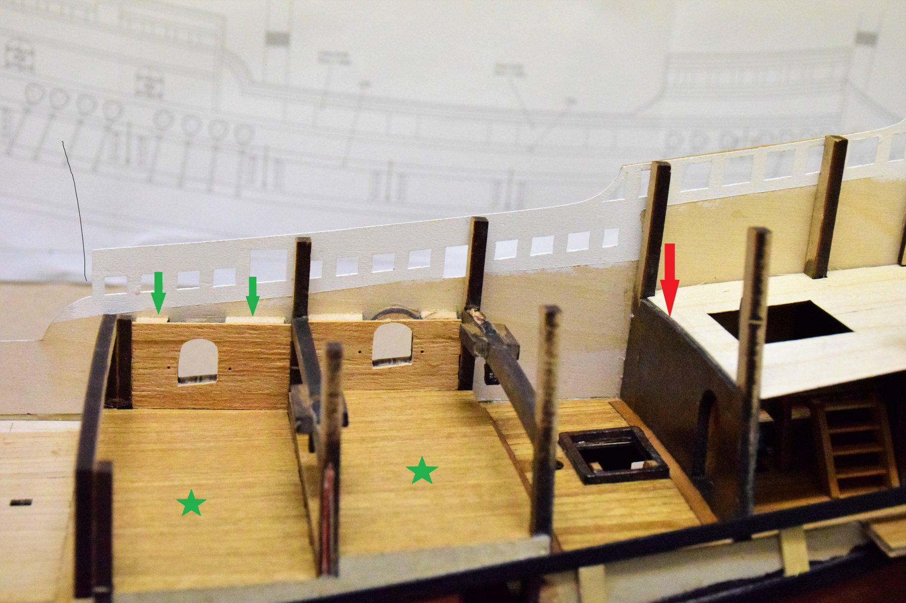
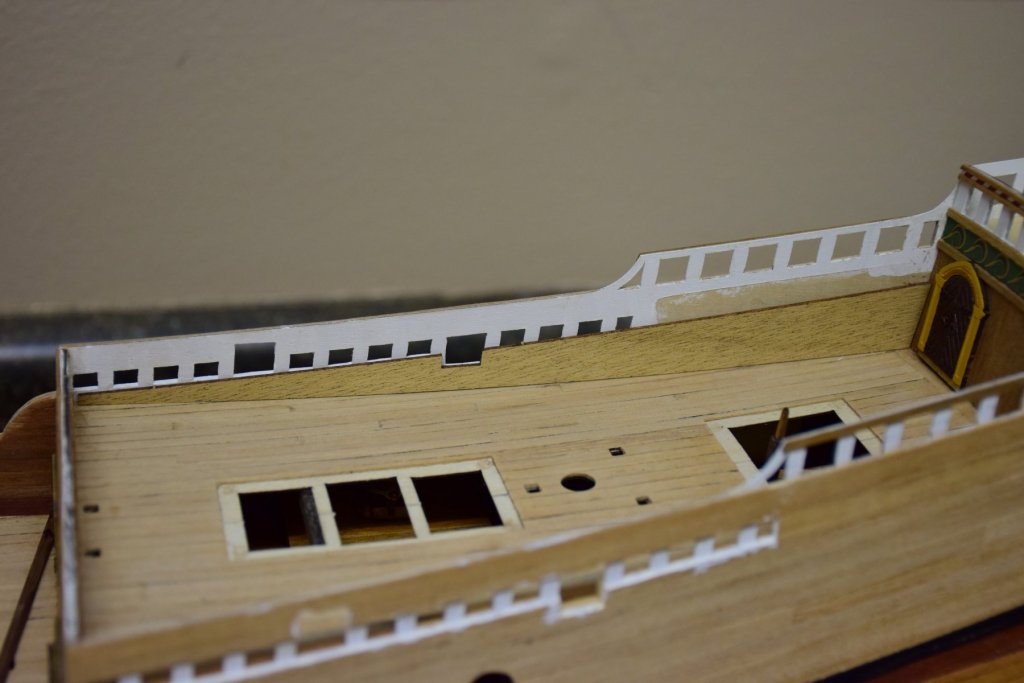
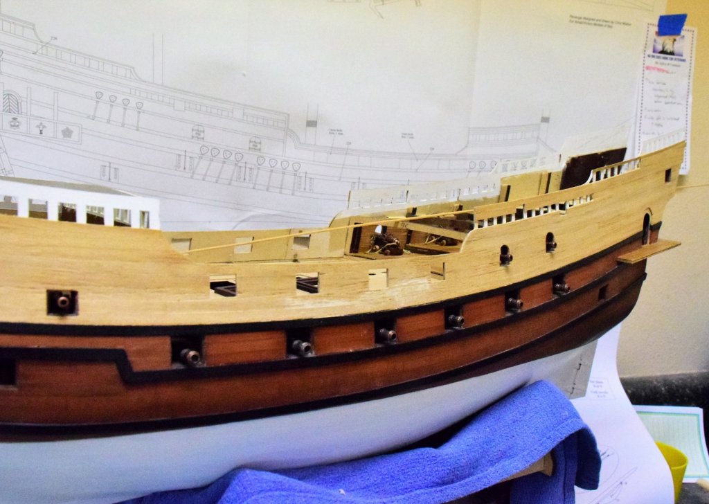
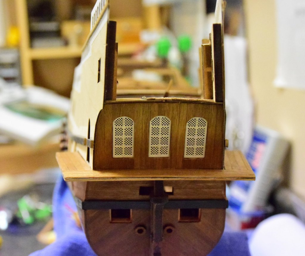
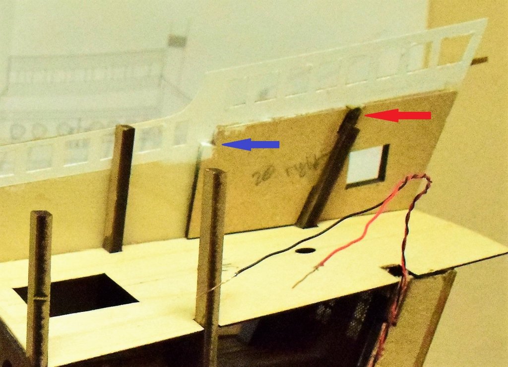
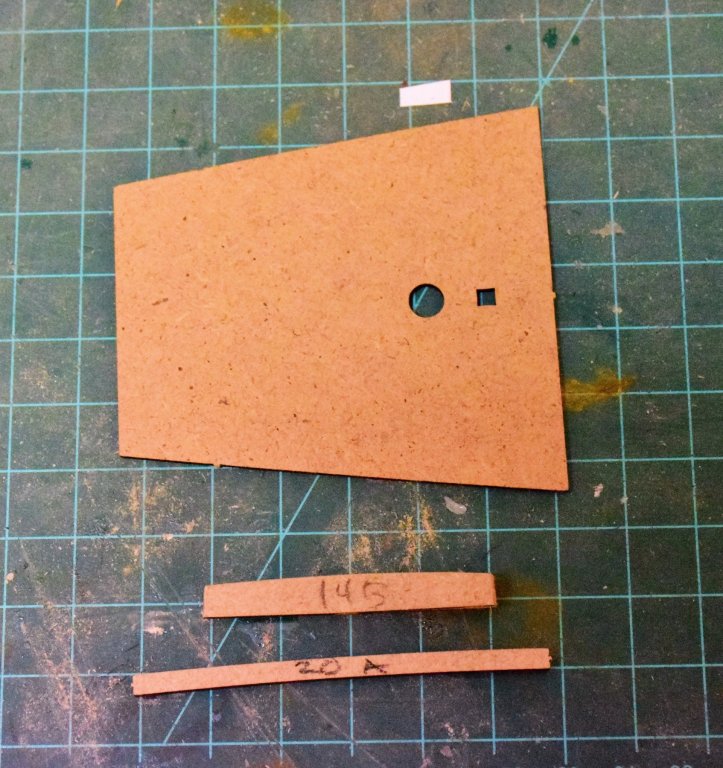
Time for a new update: The 2 raised upper decks have been planked and installed. This was all pretty straightforward (green stars). I decided to plank the inner bulwark on this deck as I did with the main deck. To support the planks I used MDF from the same pallet as the gunport frames to keep the depth the same green arrows). The planks are 5mm. The cannons will be glued to the deck and rigged with the breeching tackle prior to the installing the quarterdeck. Another modification was to divide the quaterdeck into 2 sections at frame 12 (the one just forward of the whipstaff assembly (red arrow). The work aft of this frame is complete allowing this part of the quarterdeck to be installed at this time. Before placing the cannons, the side patterns will need to be installed so the external planking can be completed. Next photo shows the starboard aft pattern in place. I have also completed the placement aft of the upper wale, leaving a space for the balcony door frame (red arrow). The stern window bulkhead and stern windows are installed before the side patterns. The poop deck side patterns must also placed at this time (blue star). I also had to glue the top the frame 14 (blue arrow) back in place as both sides snapped off during the hull planking. That happened to several frames at the forward deck too. below is work on the aft section of the quarterdeck. this will be eventually covered by the poop deck with a bulkhead at the forward end of the poop side pattern. Both side patterns now in place. I have also placed one 2x1 walnut strip across the upper part of the pattern this acted as a guide to help finalize the position of the black wale below so that there will be the correct amount of space for the colored patterns that will be added later. While doing some rough fitting of the poop deck, I decided to discard beam 14B which goes where the red arrow is on the photo below. This beam has a slight camber and for some reason, the poop deck is twice as thick as the other decks making it fairly difficult to bend in this way. Also, there is part 20A which is not listed in the manual but goes across the forward part of the side panel (blue arrow shoes the notch for this beam). Photos from the instruction manual do not show a notch here. This small camber is not really noticeable so I just replaced the kit beams with 2 from some spare wood (4x5mm). Forward side panels will be installed next Jeff


-
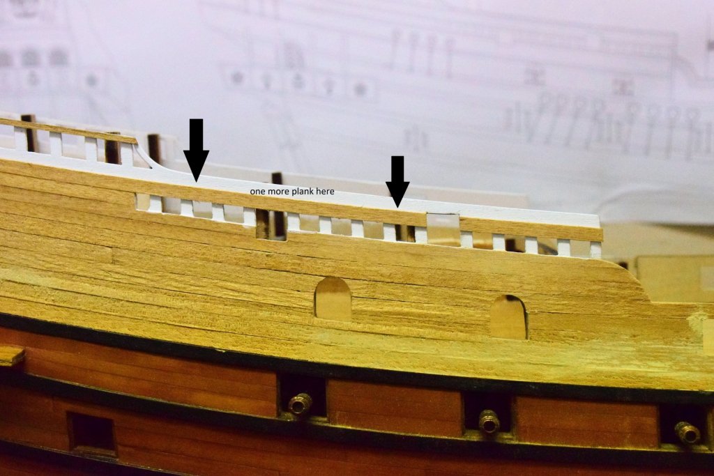
I don't think that is a "gap" but rather a transverse plank. only the tabs are left unplanked as they slot into the last bulkhead. Many of the decks have this transverse plank up against a bulkhead. Easy to fix you can just lay one of the 5mm planks used for the hull planking across this deck. jeff
-
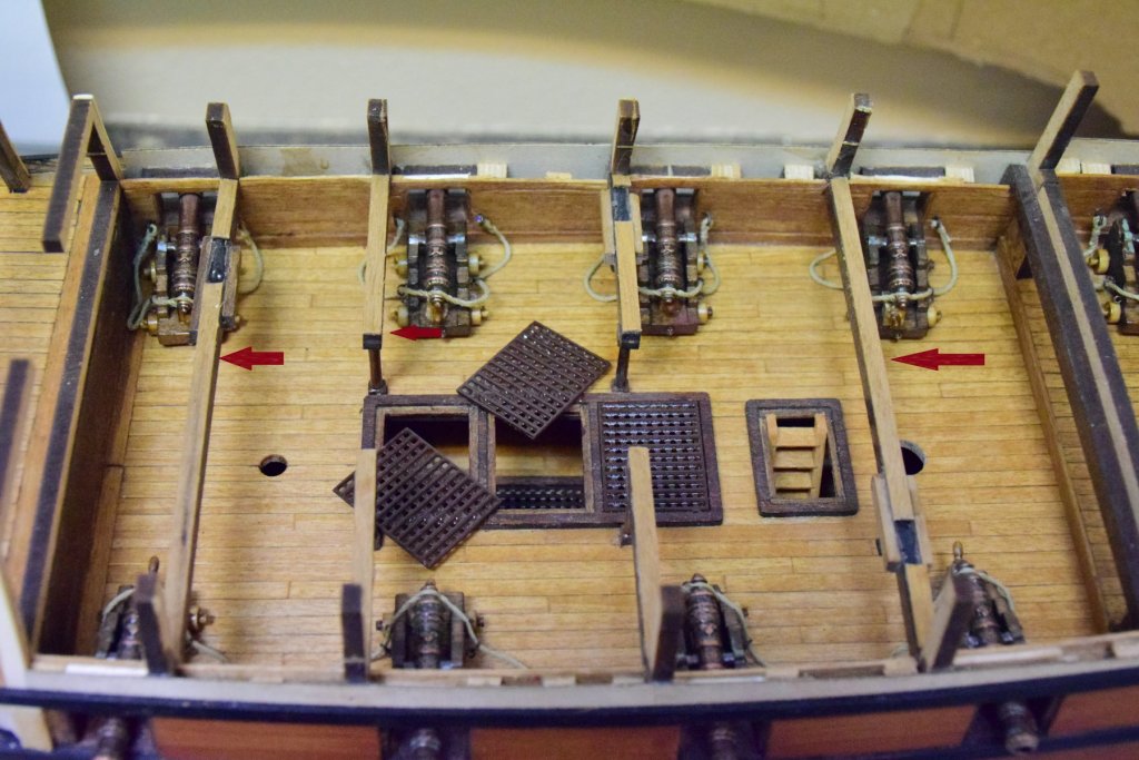
Greetings Upper deck work in progress. First pic shows some 1x4 mm wood added to each beam to raise up the cannons relative to the lower edge of the gunports (pic 2). The main deck gratings have also been placed with epoxy rather than CA - lots left to do with this model and I don't want them to get dislodged - thus completing the work on the main deck. When performing these modifications it is important to check that it causes no change to anything else further down the line. for instance two bulkheads sit on this deck and they must align with the top edge of the forward and aft side patterns (which they still do). The instructions call for planking the upper deck almost in full then installing it. Problem here is that there has to be some bending to get the deck in place. This would be difficult fully planked. So a few planks were placed off the ship to get thing started - the aft plank that runs across the deck ship (large black arrow) and the planks that run centrally up to the openings for the bits (small arrows). it is much easier to sand these openings and those for the masts while still off the ship. Once on, the deck is planked almost to the bulkhead frames (which eventually will be removed). Also seen on this deck is the hatch combing which had to remade as the kit's combing was pretty much destroyed when I tried to sand it. This part is made of a wood called dibetou. I am not a fan of this wood as it is VERY brittle along its grain. even cutting out pieces from the pallet may cause the part to split along the grain. Here's a pick of the original part (upper) and the beginnings of the new one. I have a feeling I will be making more scratch parts along the way! The red arrow shows the tiny tab that hold the part to the pallet. grain runs the same way as the arrow is pointing. Below pic shows the final hatch combing Again I digressed a bit from the plans which call for planking the deck and gluing the combing onto the planking. In reality the combing would sit on the beams and planks placed around the combing. This gives a better look I think as well as being more accurate


-
Welcome aboard! Jeff
-
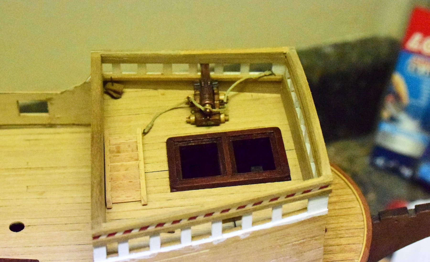
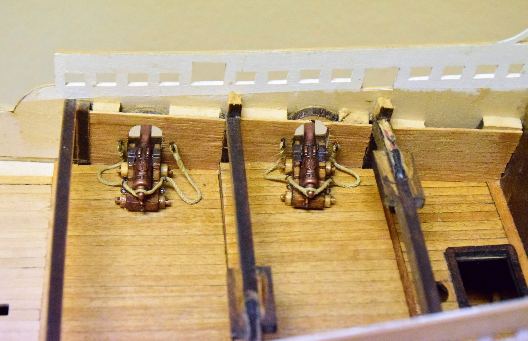
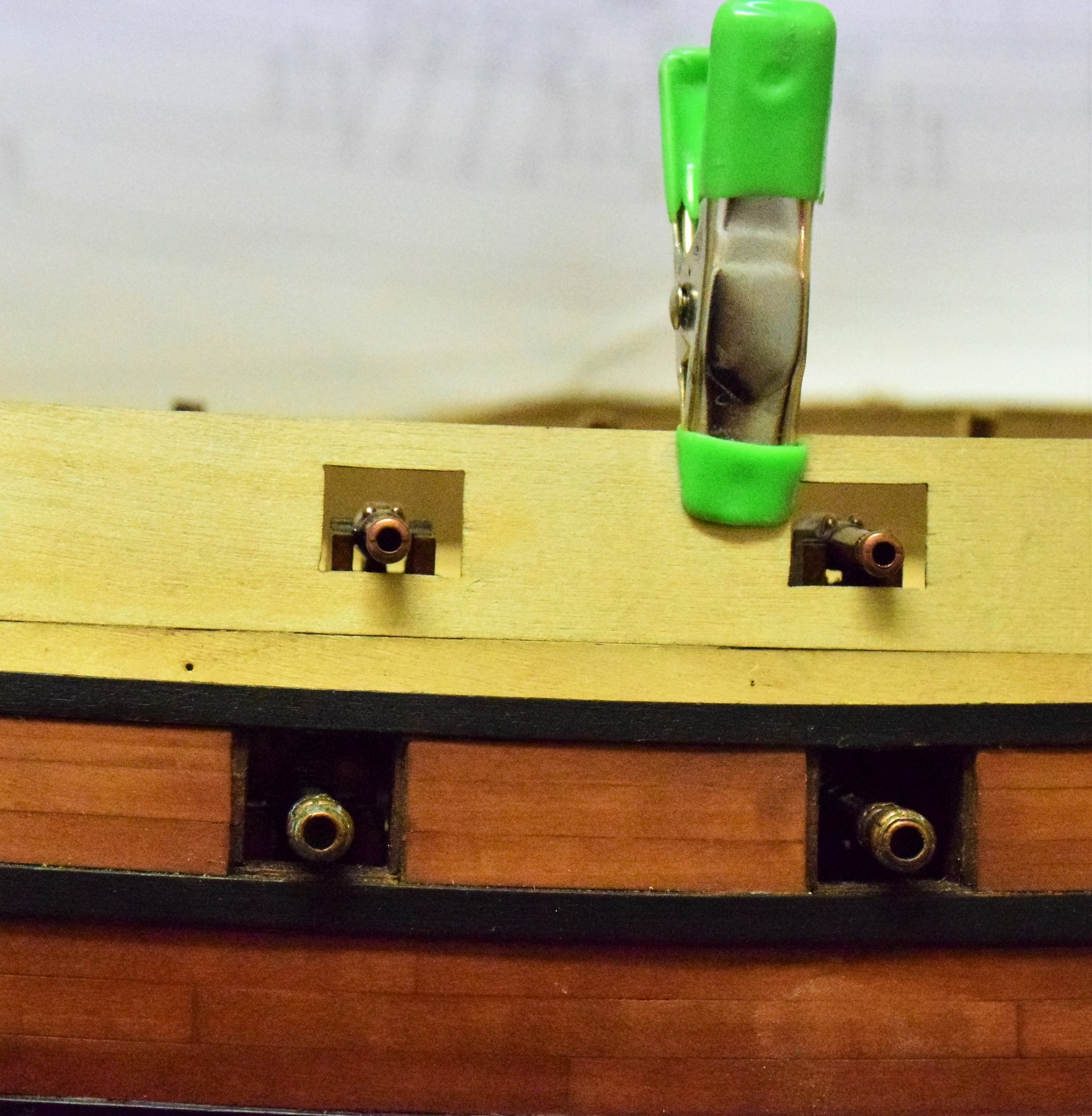
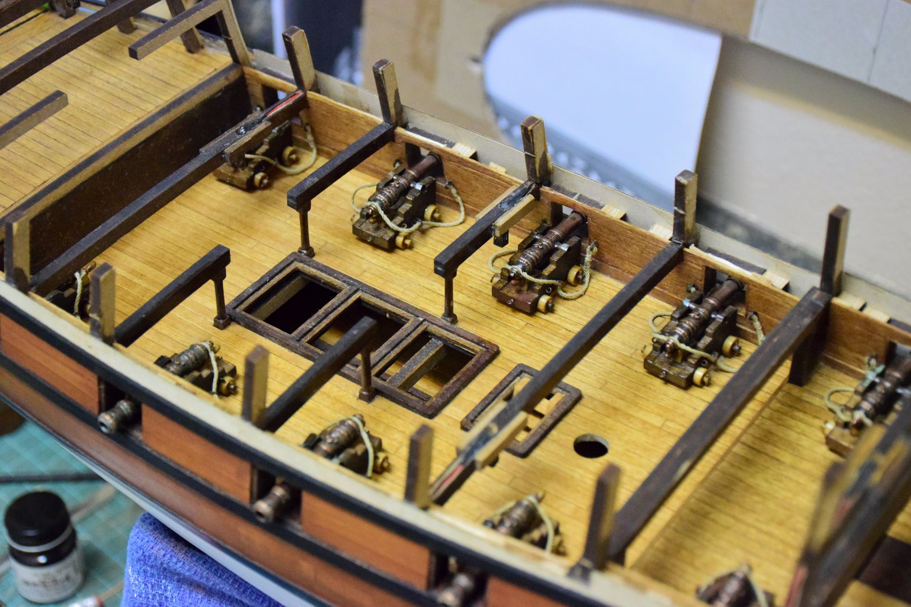
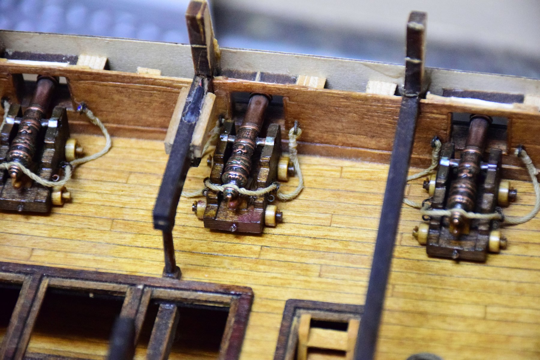
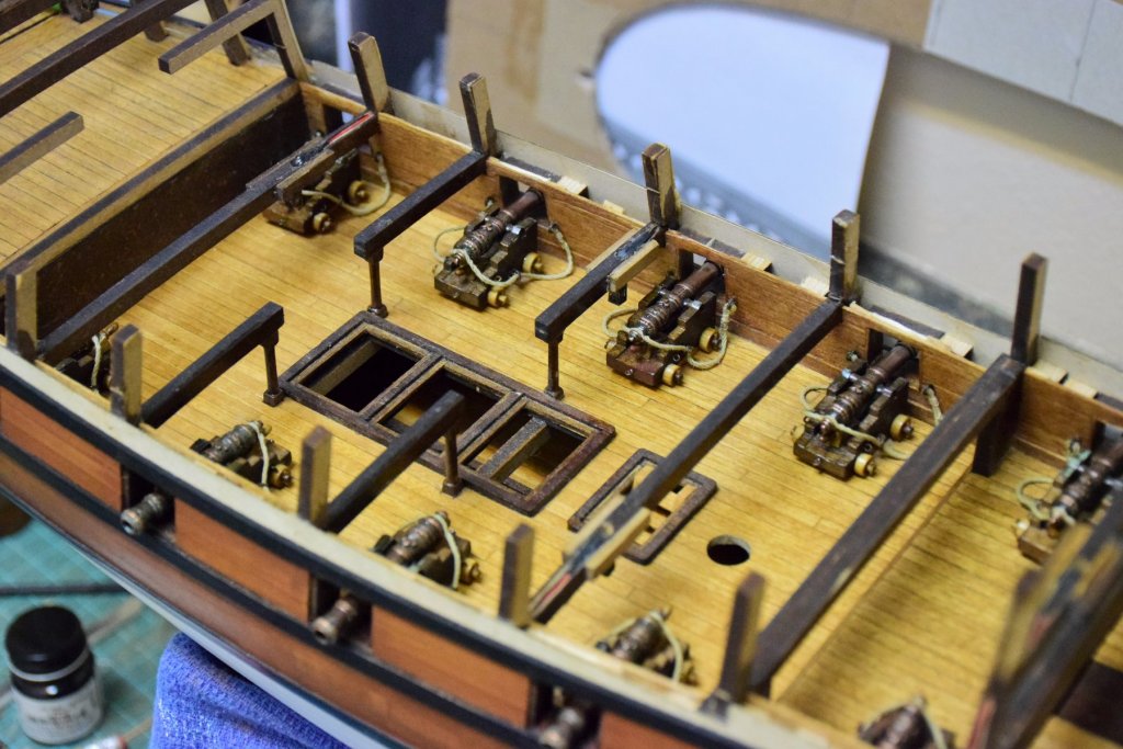
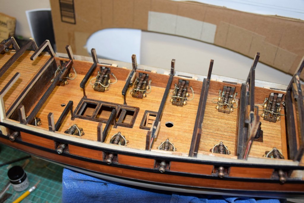
Gunports are now complete except for the application of stain and hardware. The lower deck gun are now in place with the breeching tackle. In order to get a secure bond, some spare wood was glued to the bottom of each carriage so as to create a larger surface area than just the 4 wheels for the glue. Kit instructions call for just the carriage to be placed with the guns going on later. With the guns in place now, I don't want to accidently dislodge them. They are all pretty solidly in place. I decided to leave the cannons as supplied (bronze) rather than paint them black. Cannons of this age were made of bronze or iron. Also, they are getting a little patina as can be seen below. Makes things a bit more interesting I think. Last item to add to the lower deck are the gratings. In doing some preliminary work with placement of the upper deck, I found that the cannons seemed to be a bit low, even when accounting for the deck planking. this can be seen with some of the pictures of the model on the box. some spare wood 1 x 4 mm was added to the top of the beams and problem solved, However, I also encountered this with the forward side pattern. once again another port slightly off. This gun also sits quite low on the box top photos. I plan to cut out the penciled area and fill in the same amount at the top. This will not have any overall effect on this part of the hull. For now, next up is lower deck gratings and upper deck placement and planking Jeff


-
Hi. I am one year into this model so please feel free to send a message should you have any questions Jeff
-
Hi Paolo Thanks for following my log. I am not a very speedy builder as you can see from where I am in this build. Re: the deck plank lengths, I started with a full sized length of 24 FT which is ~ 4.5 inches at a scale of 1:64. I think I decided on 4 inch planks for the model. To make it easy, I would recommend a plank length of 10 cm. This would also make it easy to shift the planks 2.5 cm with each successive plank so joints on the same "beam" would be separated by 3 planks. Feel free to ask any questions along the way. hope this helps Jeff
-
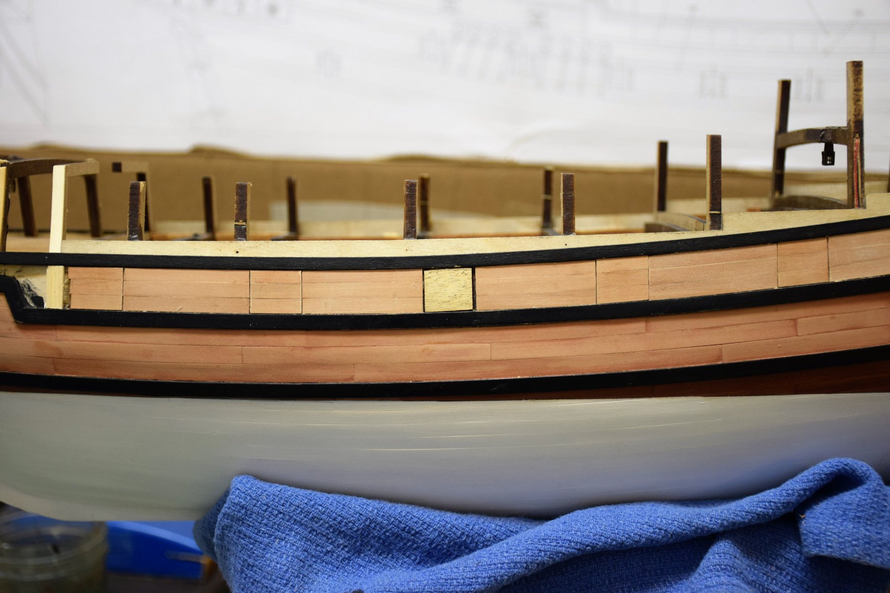
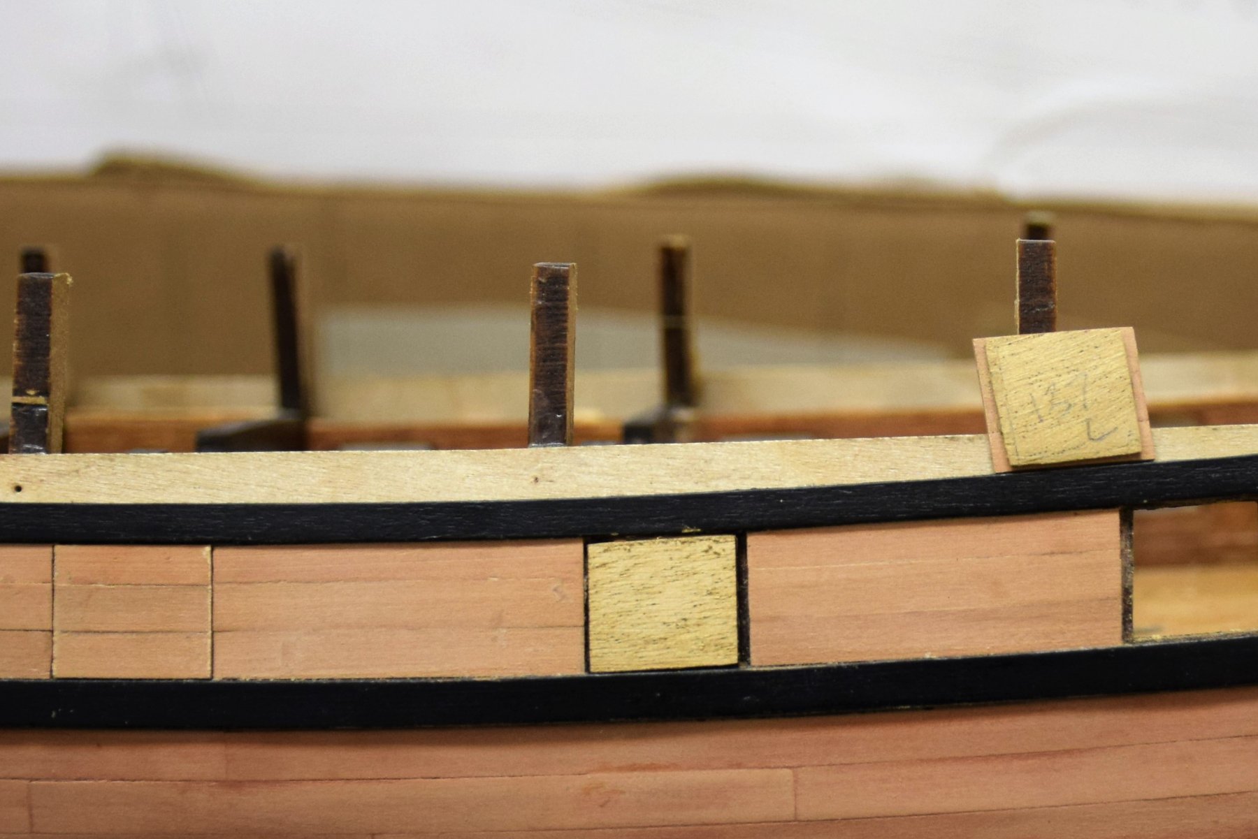
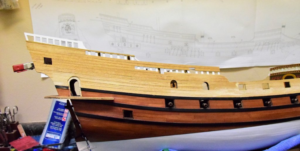
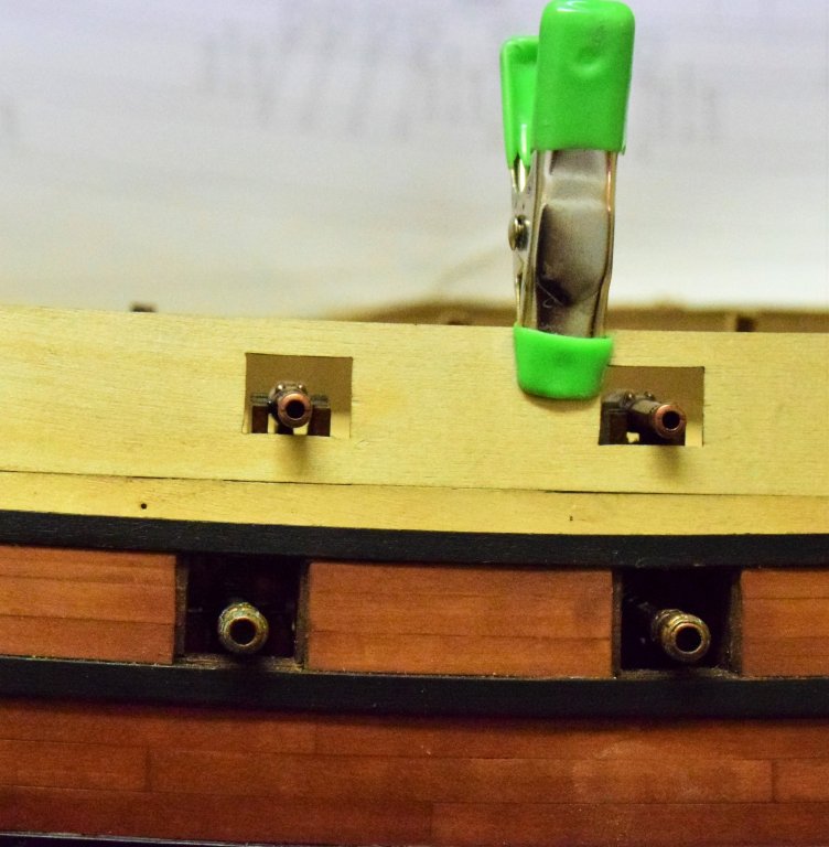
Planking between the wales now complete (glad to be done with all the complex curves at the bow!). Instructions call for completion of the remaining decks before placing the fore and aft side patterns. This would require placing the lower deck gun carriages without the guns. As I want to rig these guns with at least the breech tackle, some changes in the order of construction will needed. First, I decided to plank the spaces between the gunports so these areas could be sanded and finished prior to gun placement. This would require the wale that runs above the gunports to be laid down first. As this wale runs the length of the ship, the part of the wale that would be fixed to the side patterns was left unglued (second pic, arrow). Also, the instructions call for the wales (lower 2 are 1x5 and the upper one is 1x4)to be glued onto the second layer of planking. I felt that doing it this way this would make it difficult to exactly match the run of the planks already placed. Thus, two 1 mm planks were glued together to form the wale and this was then placed onto the model with spacers to maintain the correct distance from between the wales (first pic, arrow). the lower wales were made in the same way. After the planks were place between the ports, the port lids would have to be redone as those supplied with the kit were dibetou wood and this looked quite wrong against the swiss pear. As the photo below shows, the new port lid was made from 3 planks of swiss pear made to follow the run of the hull planks. As the supplied port lids were all cut to match their respective ports, rather than waste them, they were trimmed a bit and used to make the inner layer of the port lid (illustrated in to photo below. The hinges will be added at a later time. Next step will be to place the lower deck guns with the breeching tackle then construct the deck above. jeff

-
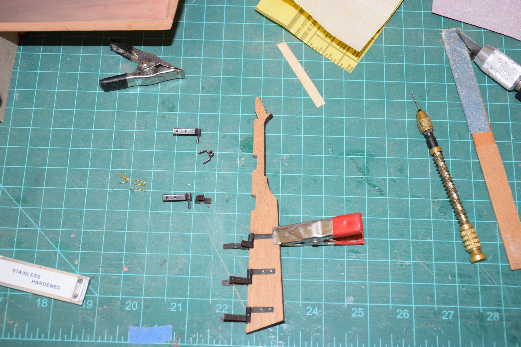
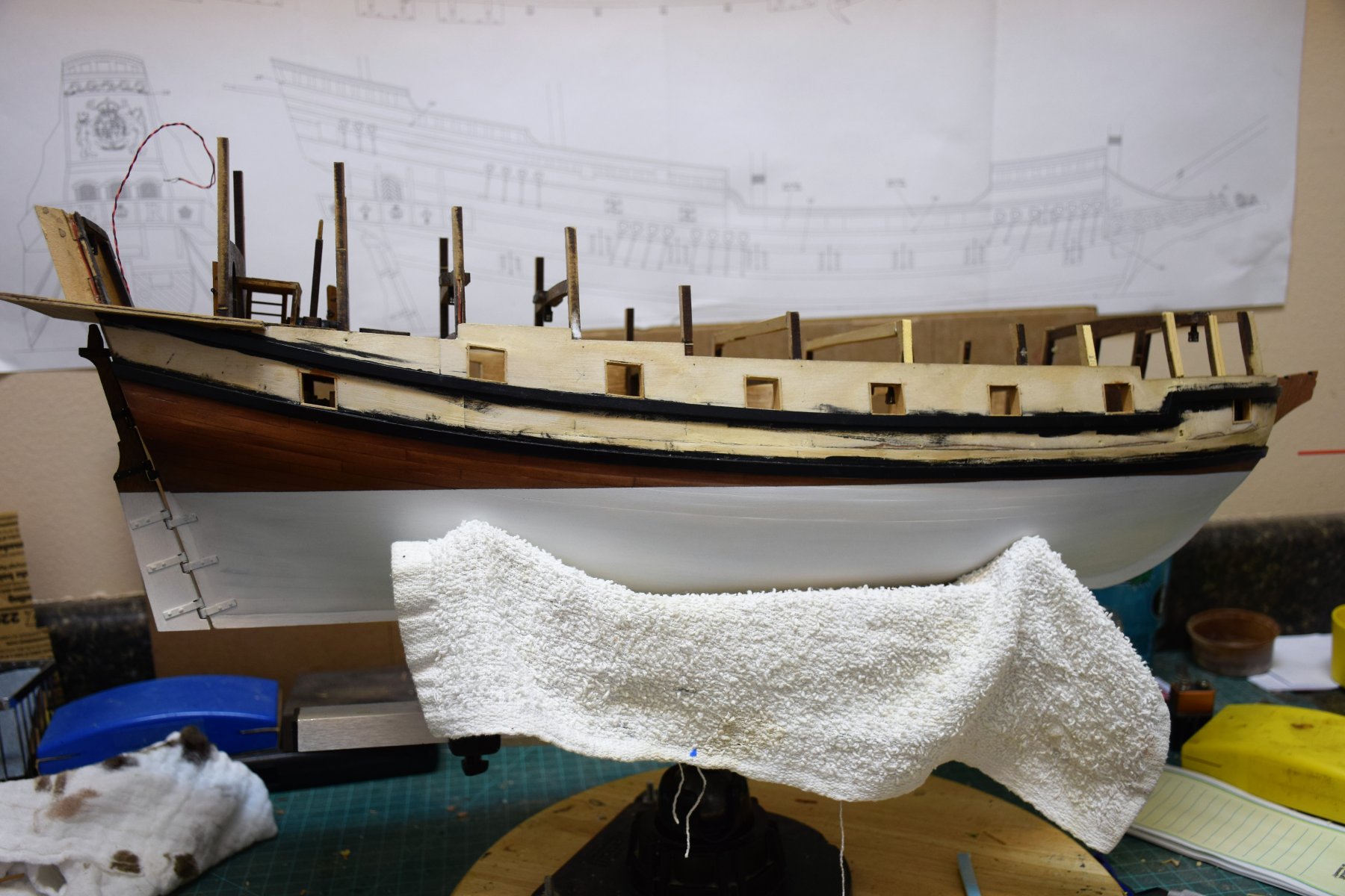
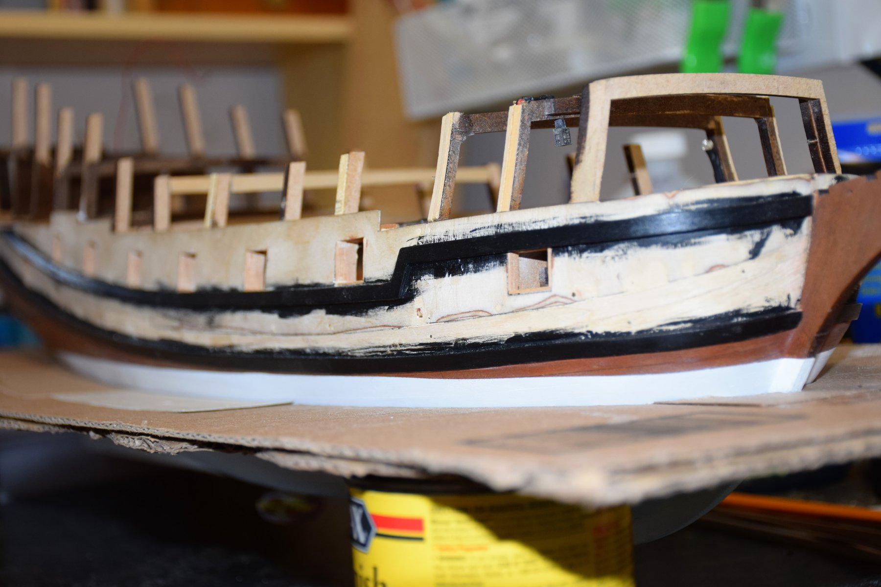
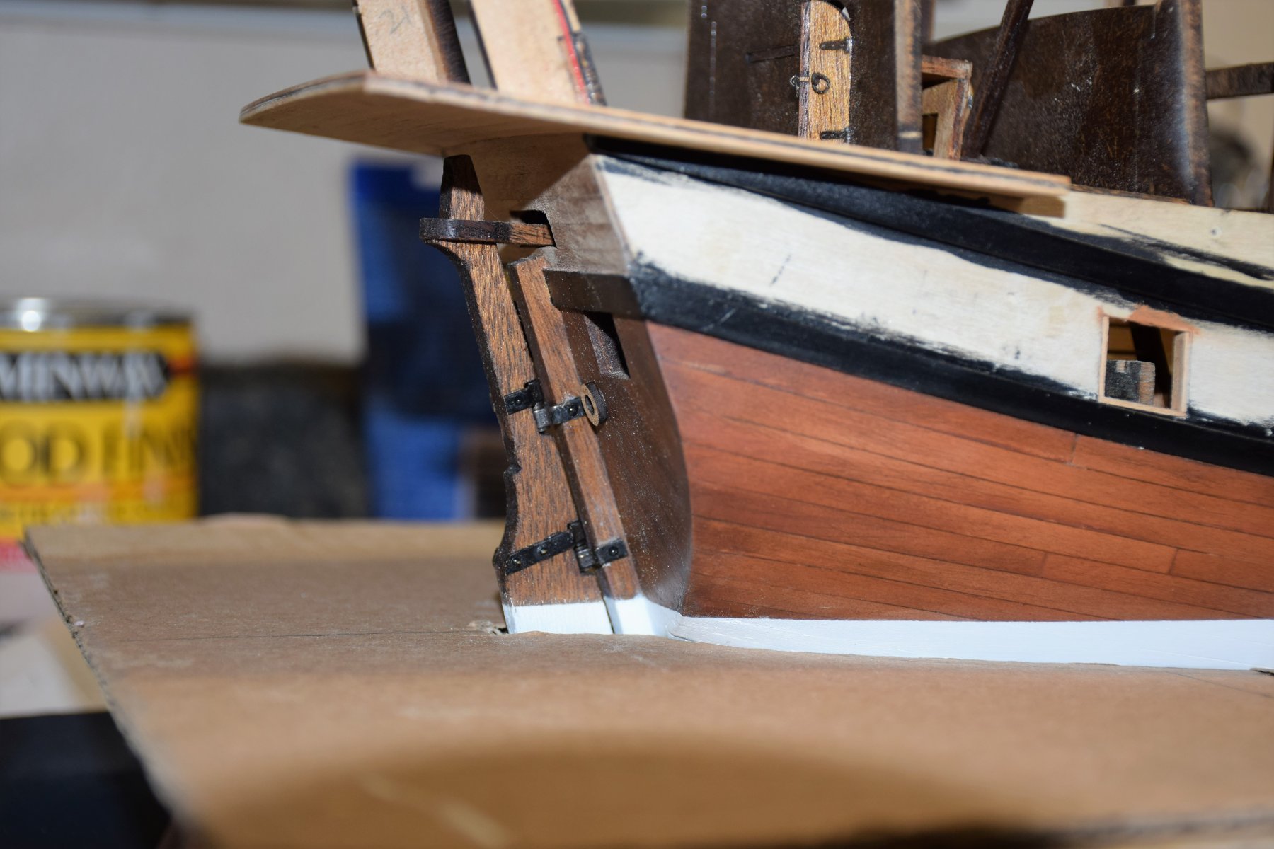
time for a new update. after the planking below the wale was completed, the waterline was drawn and then painted. this is also the time to construct and hang the rudder. The tiller arm (orange arrow, second pic) is also connected to the whipstaff assemble at this time. The quality of the rudder hinges is quite good. The gunports have also been framed. Next are a few views of the waterline... Below, the hull sitting in my waterline template... planking between the wales is next. while waiting for some additional swiss pear, work was started on the forward 2 bulkheads.


-
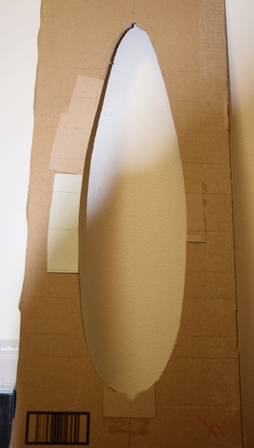
Jond, I have similar plans for my current build of Amati's Revenge - a 3 or 4 mm thick sheet of plexiglass with the waterline cut out that the ship will sit in. While I have not yet purchased the plexiglass sheet, I found this website that has a variety of thicknesses and will cut to size: https://www.eplastics.com/plexiglass/acrylic-sheets/clear Also, I used some large cardboard boxes to get the pattern of the waterline (using a contour gauge) that will eventually be transferred to the plexiglas for cutting. A photo of the template can be seen in my build log and I will soon have some pics of the ship sitting in the template. Took about 4 or 5 tries to get the waterline cutout correct. not sure about what I will use to simulate the water but that is way in the future Jeff
-
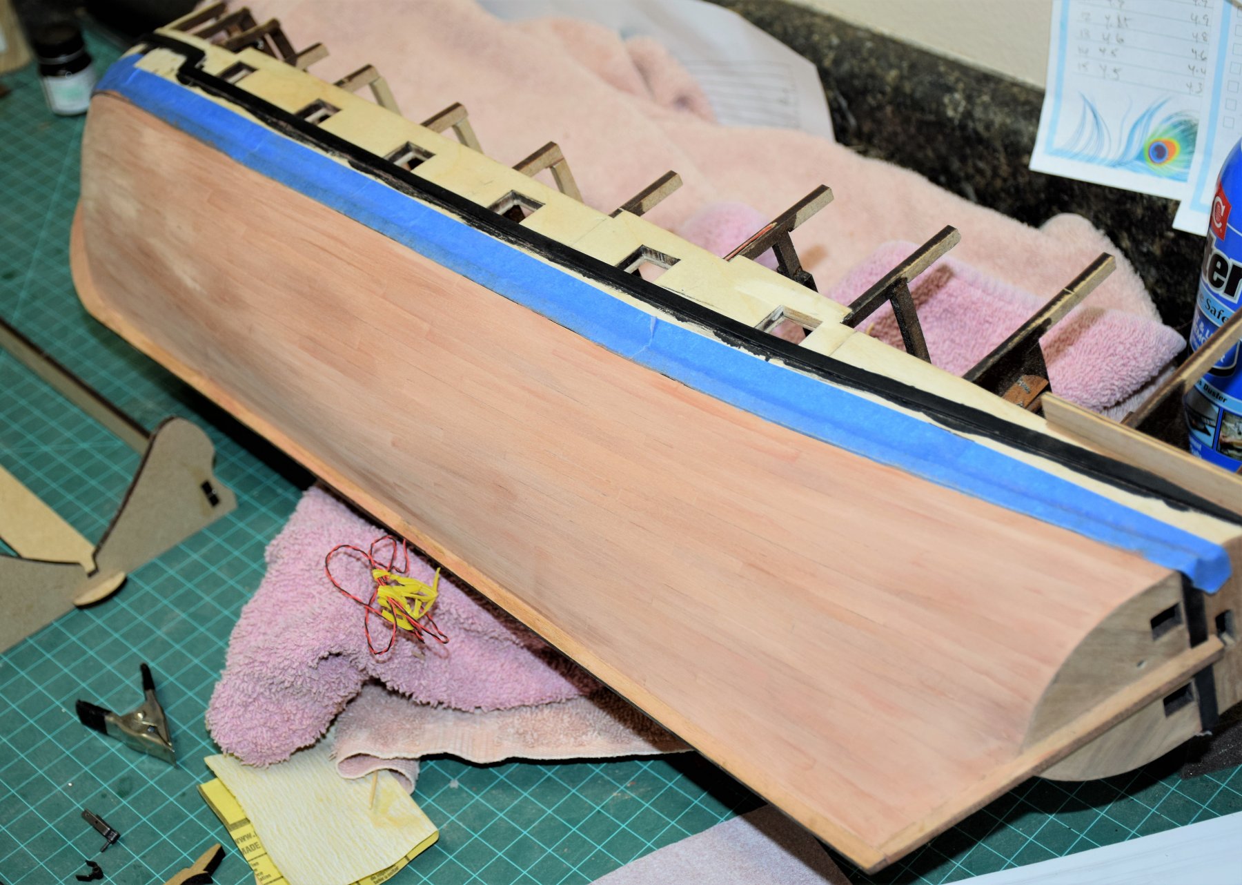
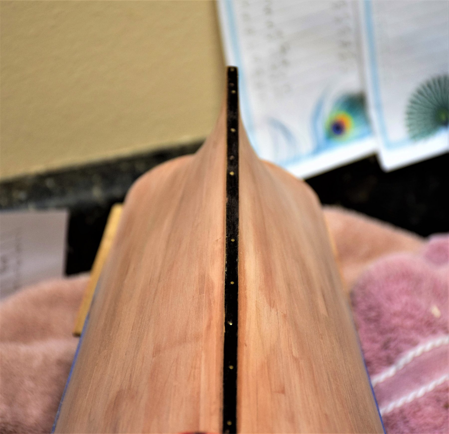
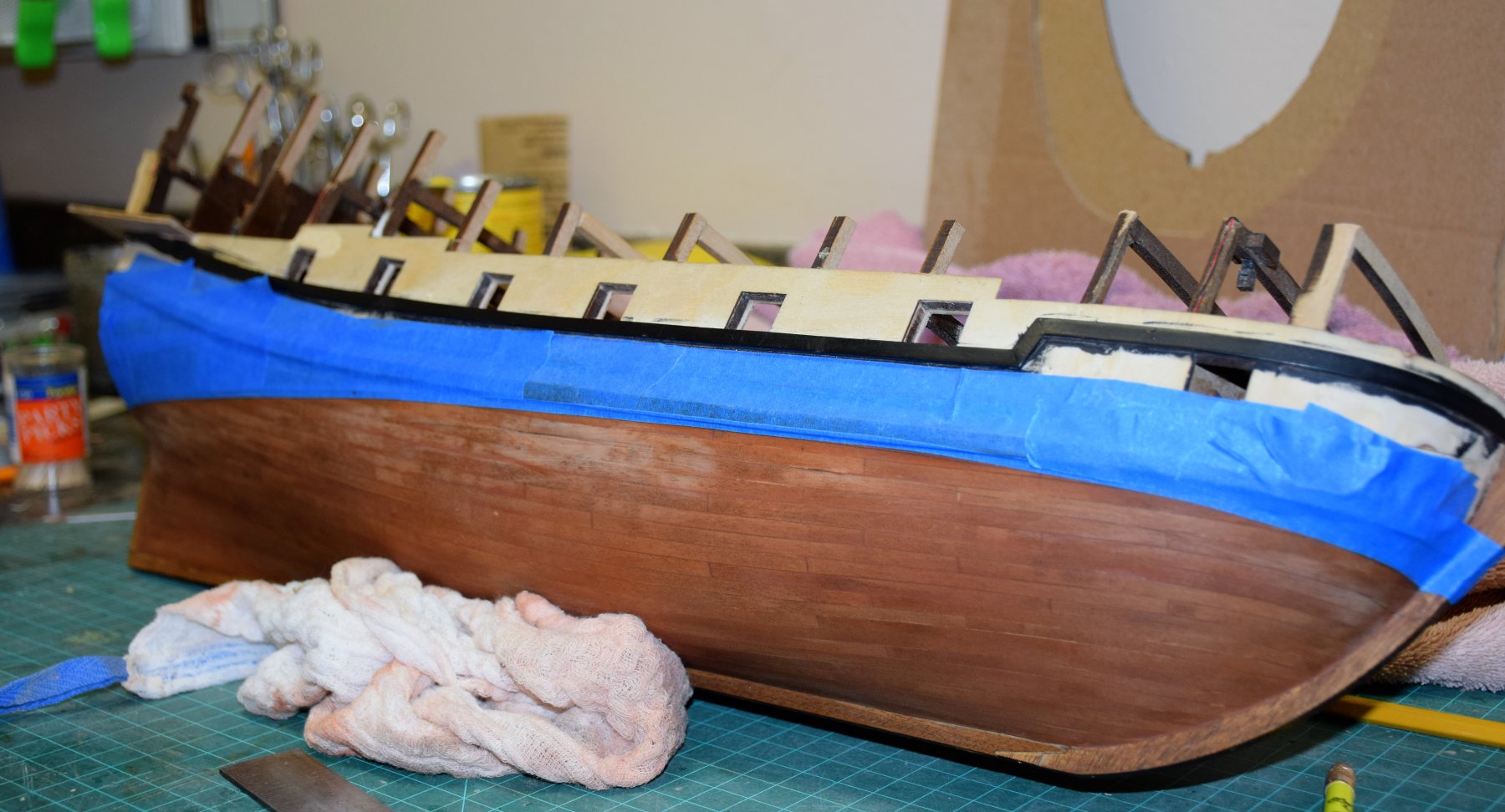
Second planking now complete. the blue tape protects the wale from sanding. no stealers were used. the largest width amidships is 5 mm however at the stern, I used 1x7 mm swiss pear and trimmed it to the correct width. After marking the waterline, painters tape applied to protect upper hull. Below the waterline will be painted white. My ultimate plan is to display the model dropped into a sheet of 4 mm plexiglass which will be used as the base for water (never did this before so should be an interesting project). below is the cardboard template I made that will provide the outline used to cut the opening in the plexiglass. Took a few tries to get it right using a contour gauge


-
Thanks for your comments. The swiss pear was much easier to work with than the wood supplied by the kit and not nearly as brittle jeff