MORE HANDBOOKS ARE ON THEIR WAY! We will let you know when they get here.
×


bthoe
-
Posts
72 -
Joined
-
Last visited
Content Type
Profiles
Forums
Gallery
Events
Everything posted by bthoe
-
 Thanks for the likes folks, and I promise that you will see more photos as I get to detailing those particular areas. In the meantime, if you are interested in anything in particular, just ask - I'd be happy to share anything I have. Hi Gregg, It wasn't all bad about the masts and spars - I did get a LOT of details on them because they were on the ground that I could have never seen way up in the air. Yes, the ship was open. As a modeler, I was disappointed that some of the areas were roped off on the Gun Deck, like the bow area. I had hoped to get details of the hawse holes the bitts, and the pathway of the anchor rope. I know that I want to do things differently than as it is now, as it is set up for anchor chain rather than rope. I'll need to rely more on drawings, and online photos/videos. As for the captain's/admiral's area in the stern, it would have been nice to have access to get more details of the inner galleries, bedrooms, and stern area where I'll have windows. Again, I'll need to rely on others' photos/videos and drawings for inspiration. On the Spar Deck, the entire main hatchway was battened down (covered by canvas), I had hoped to see more details of joinery, etc. I was able to see it from below, but my view area was restricted due to deck support spars. I suppose I could have laid down on the deck and shot upwards, but the ship had other visitors as well 😉. Seriously, it was a thrill to even be there, and there was a lot to see. I likened it earlier to a kid in a candy shop - it's like you have a preset idea of things you want to detail, and it goes out the window when you see it in person! . Hi Unegawahya, Yes, I have for SURE seen that 3D site, and it's great. However, sometimes what you are most interested in seeing is in border areas of images or wasn't detailed at all. I don't mean to sound ungrateful for what is there, because there's a LOT. But I find myself thinking, "gee I wish they got X from a different angle/better detail".
 -
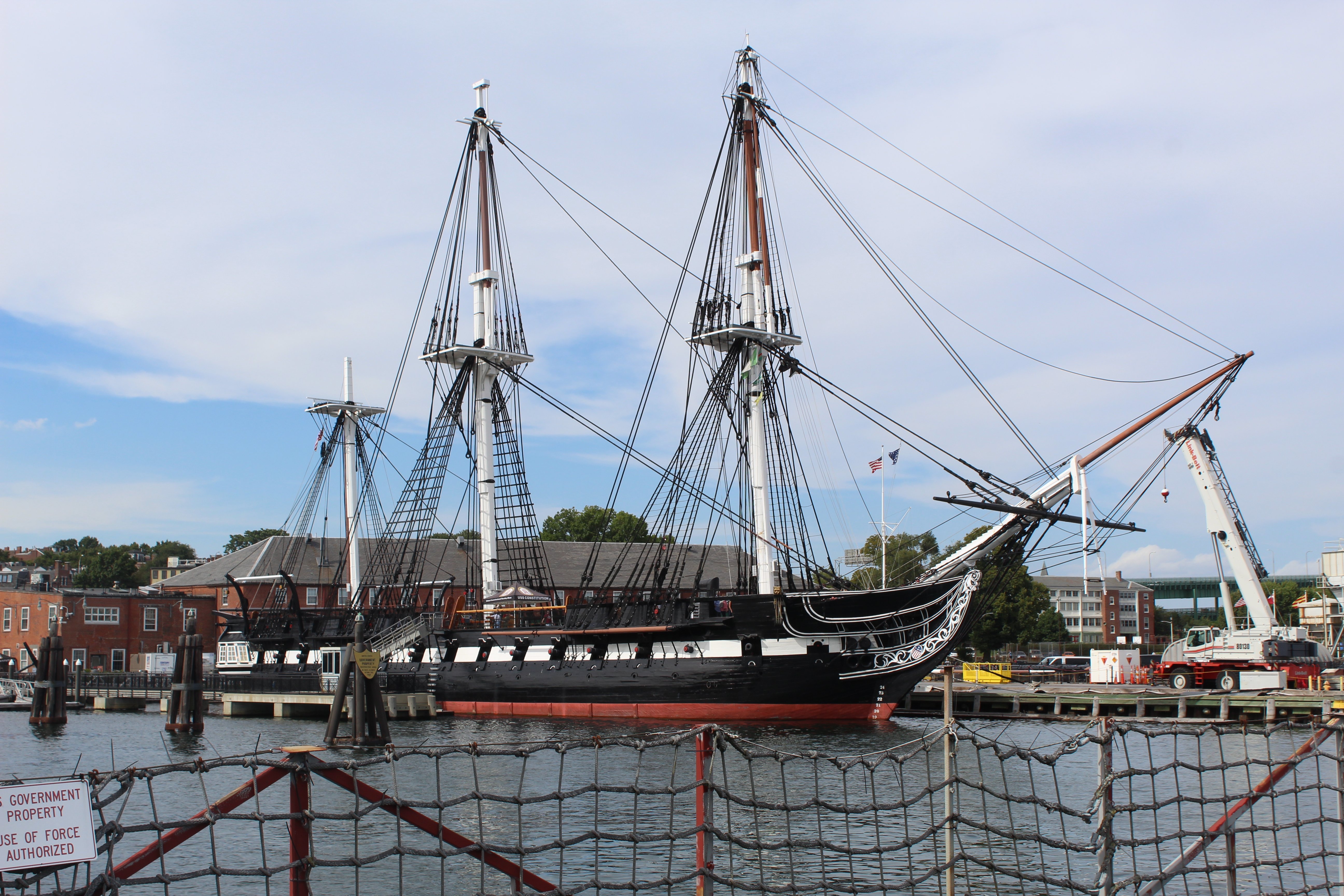
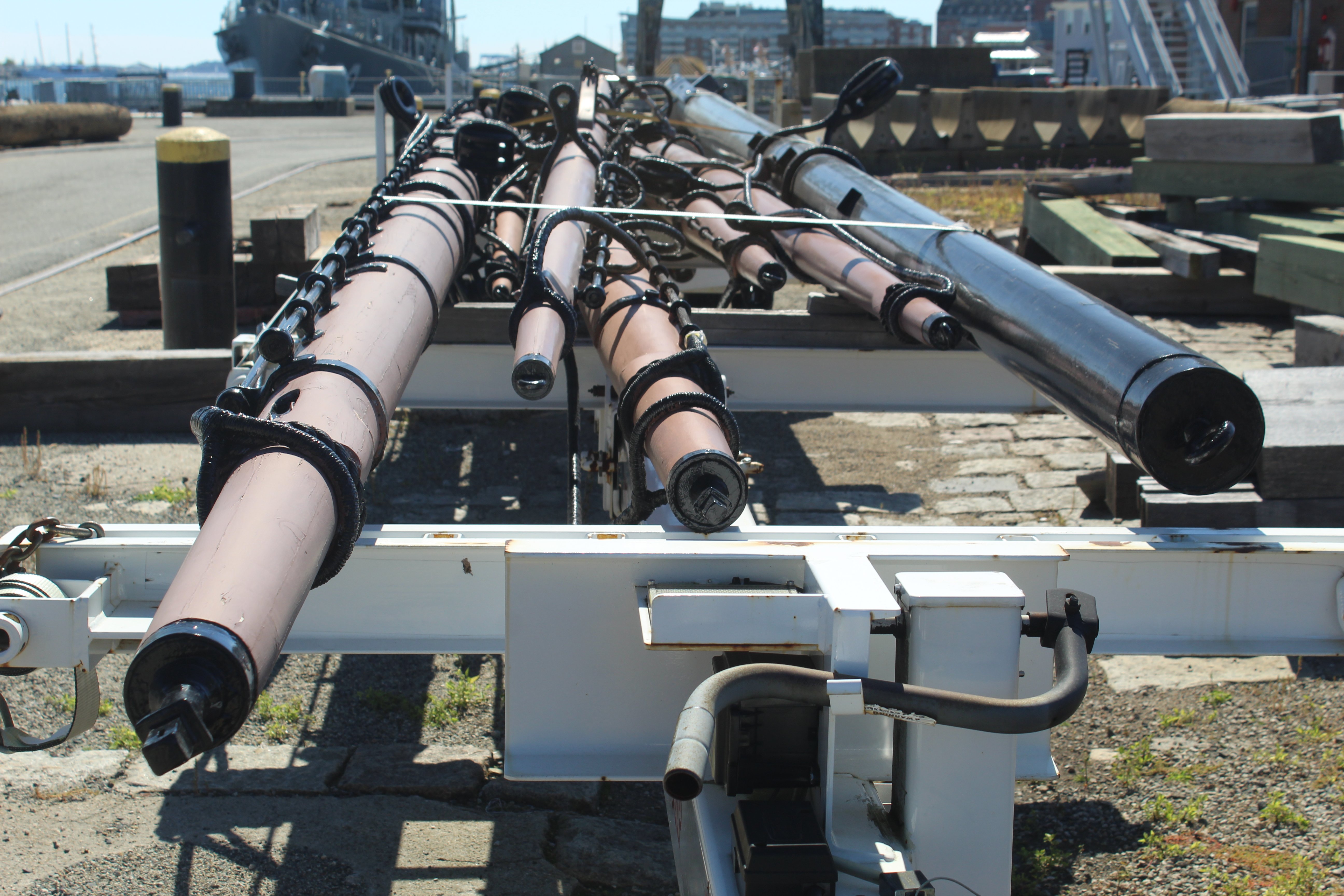
Last weekend, I visited Boston for the first time ever. Well, actually, it was just the cab ride from the airport to Charlestown and back that I went through Boston. We spent 3 days in Charlestown, just a few blocks from Constitution, and all I did was spend time on and around the ship and in the museum. I liken it to being a kid in a candy store, not knowing what to do first! Although masting and rigging are quite a long way away for me, I was disappointed that Constitution wasn't fully masted, sparred, and rigged until I noticed masts and spars on the ground between the ship and drydock. I took many photos of them from angles that I never would have seen had they been where I was expecting them to be. Anyway, I'd be happy to share what I have with any of you. It was a real thrill to see the "real thing" up close for the first time. I hope you all have the chance to see it sometime. My best,


-
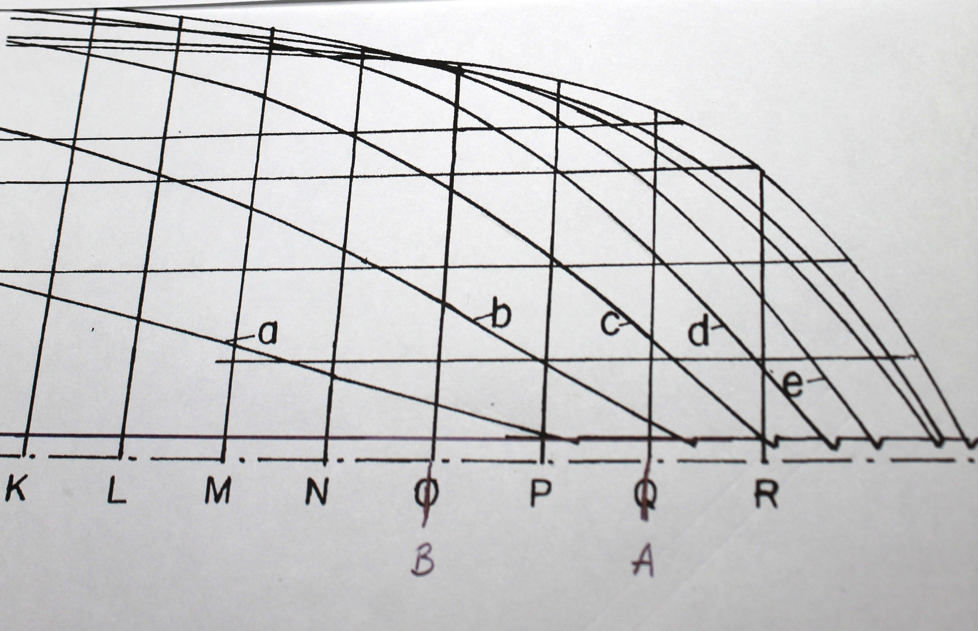
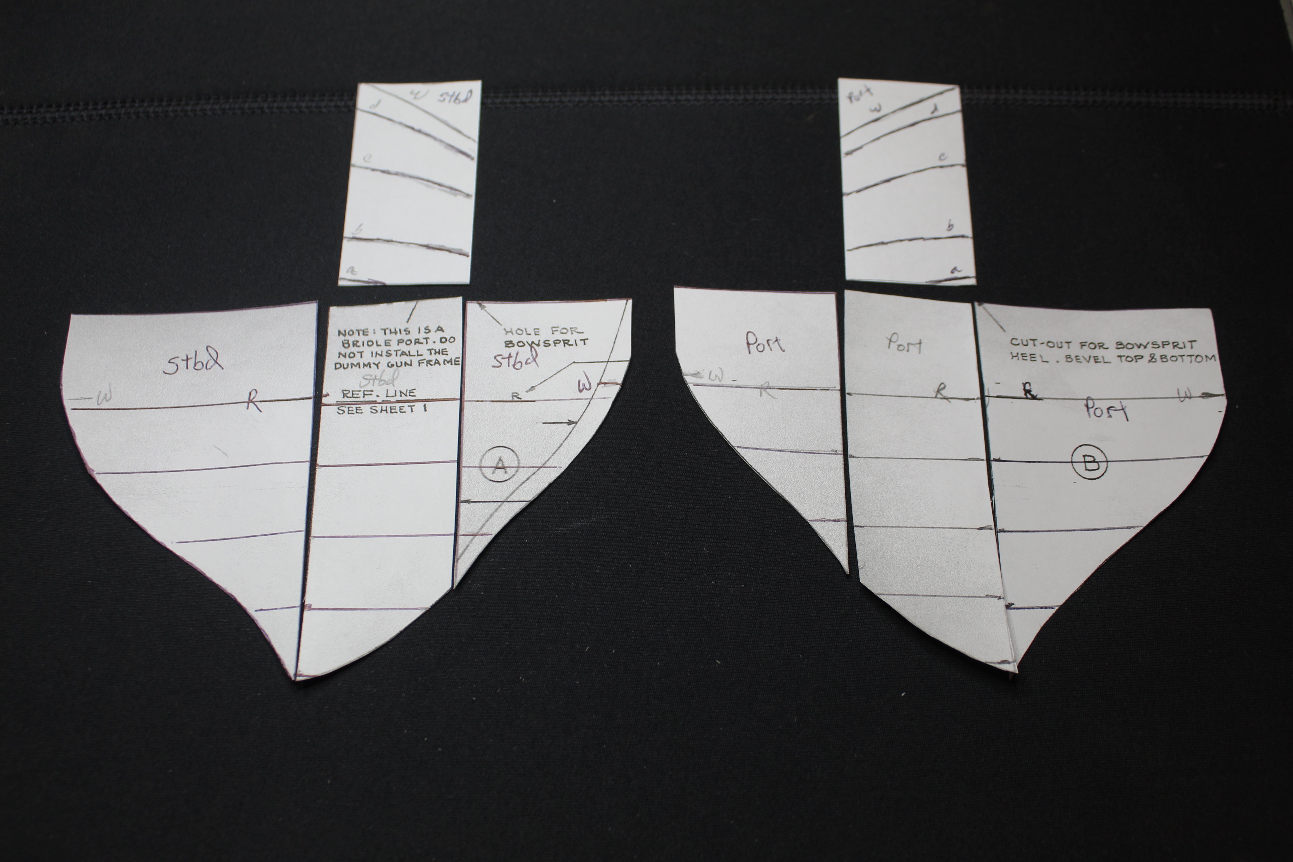
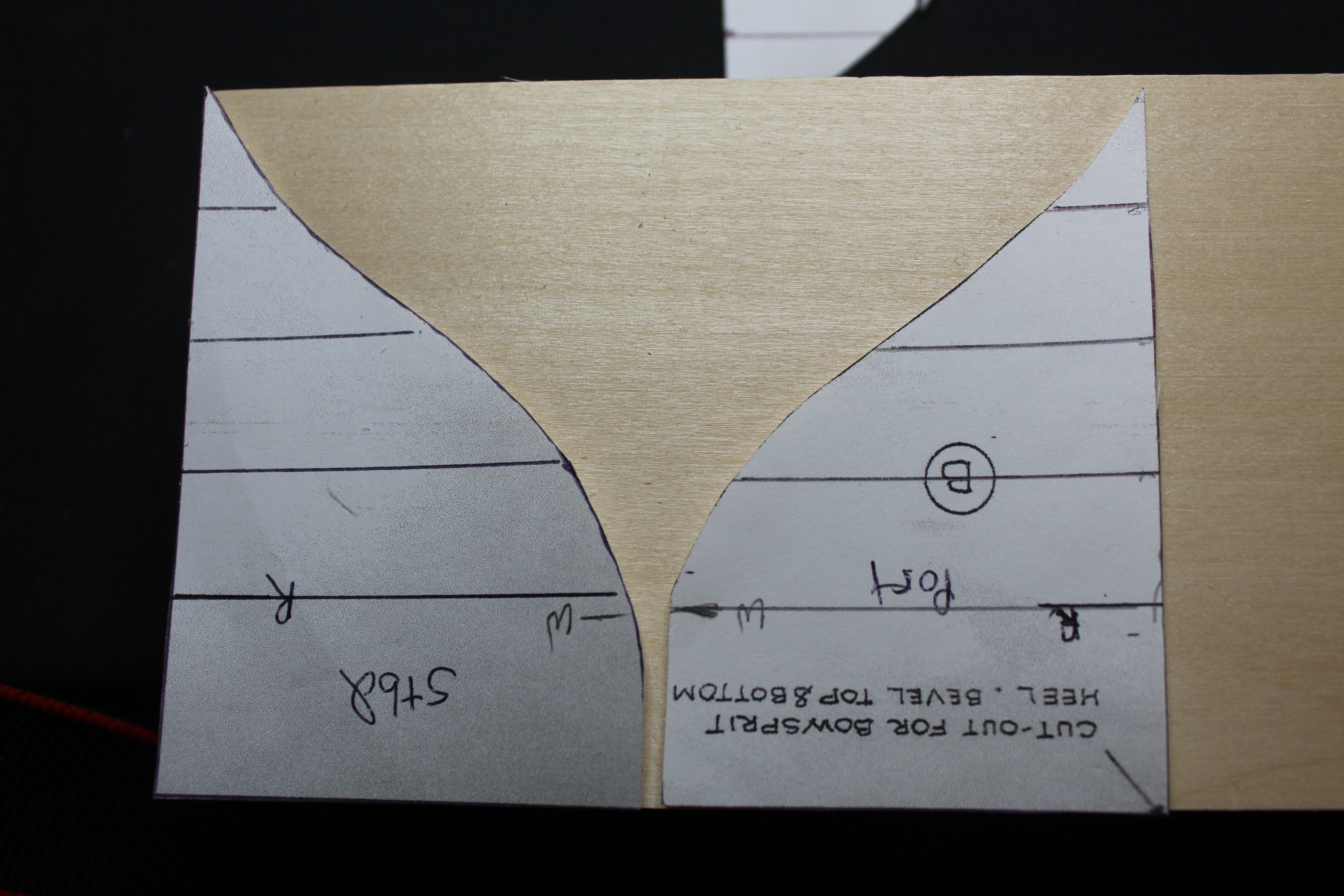
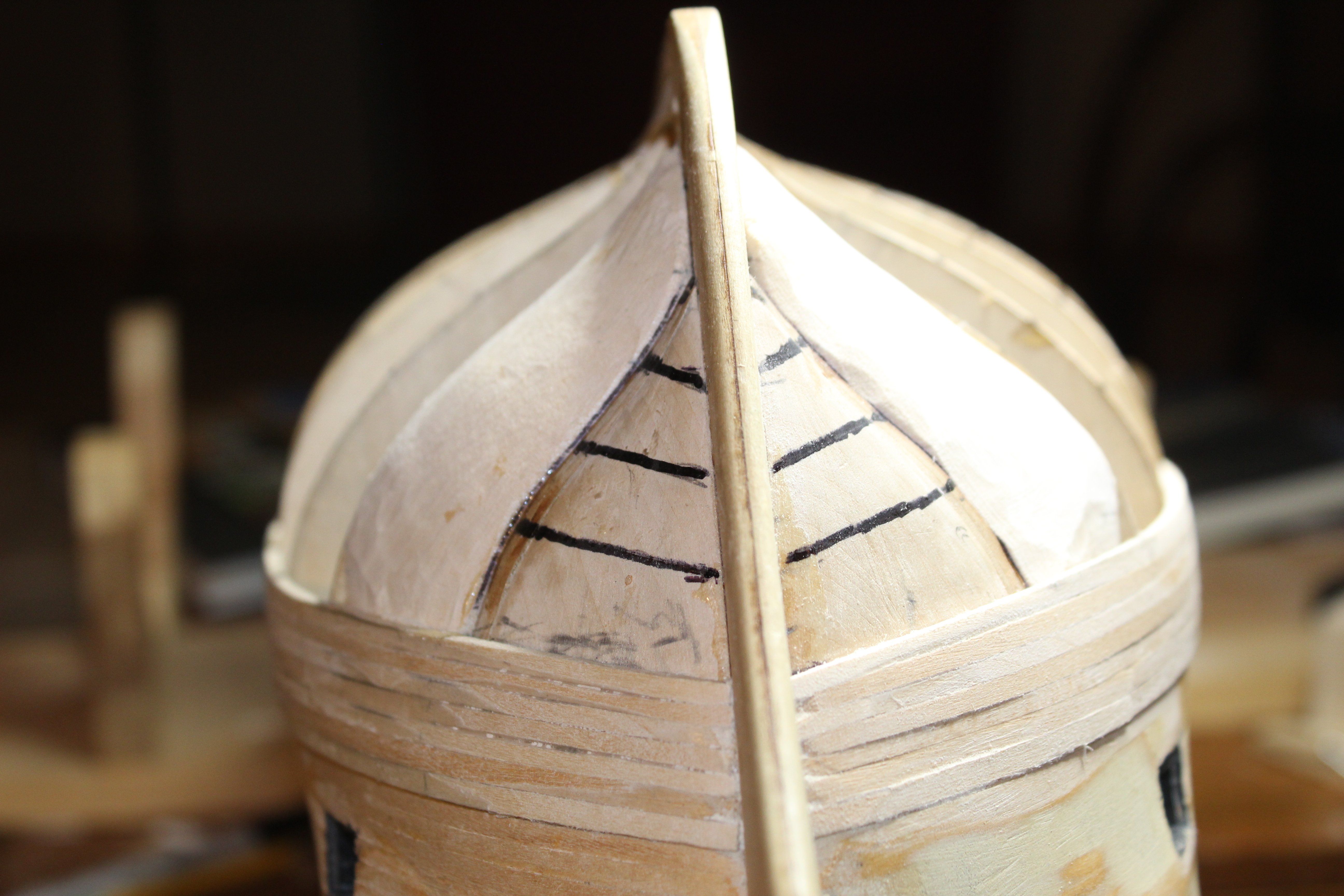
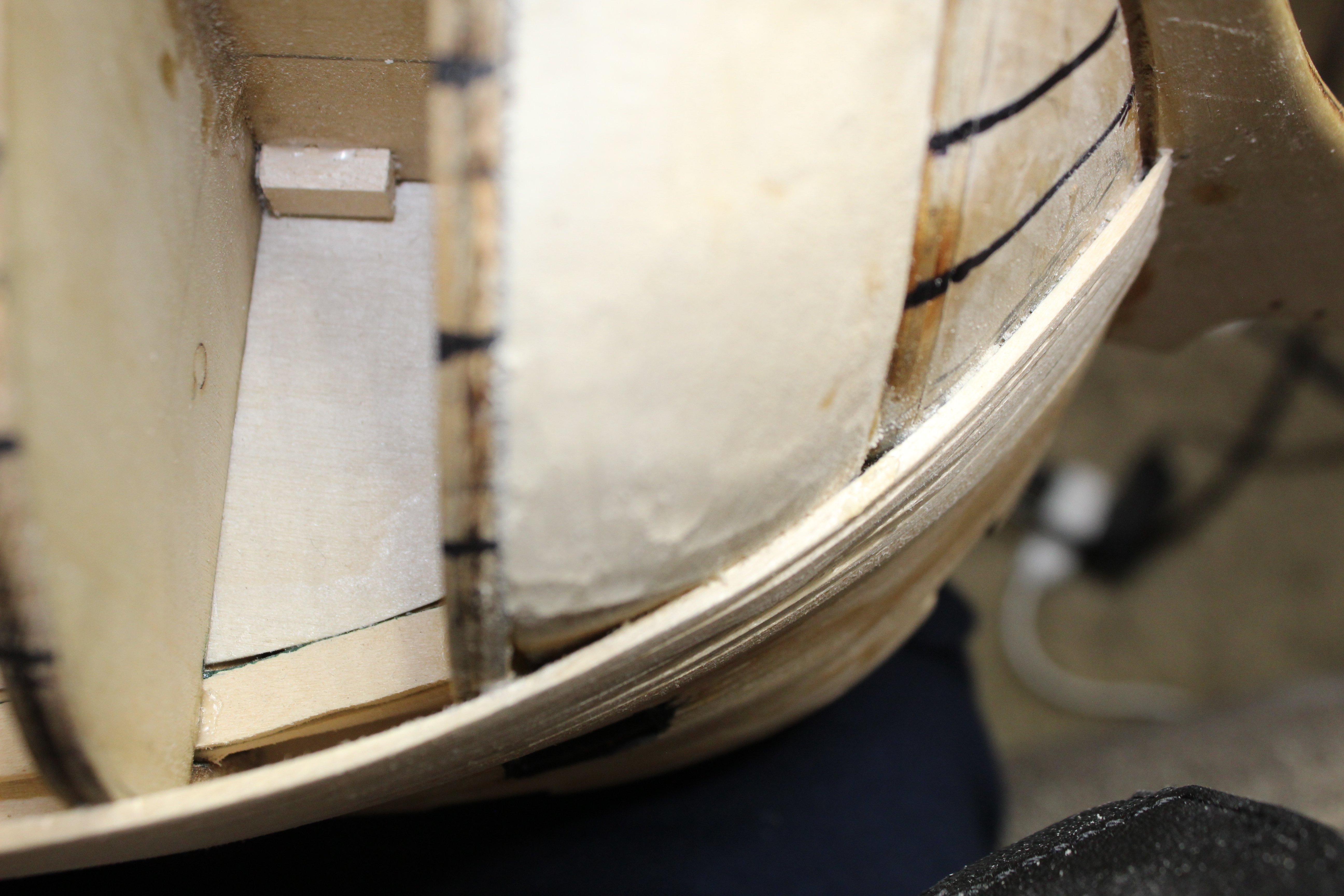
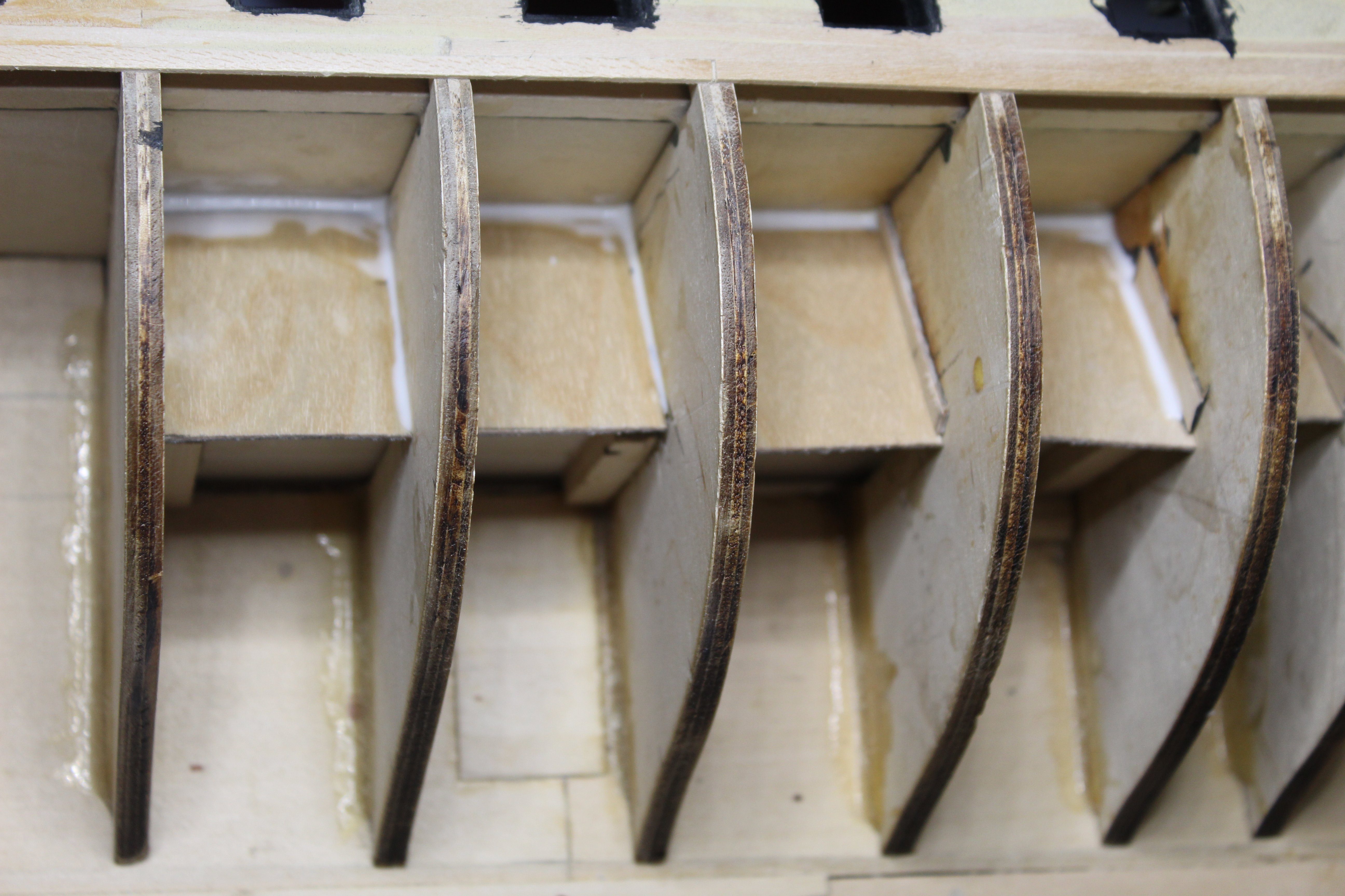
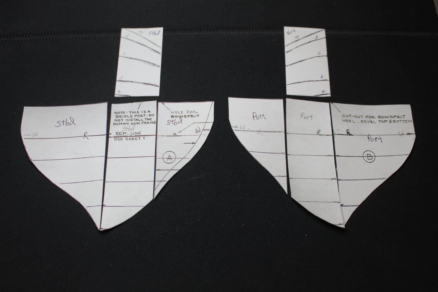
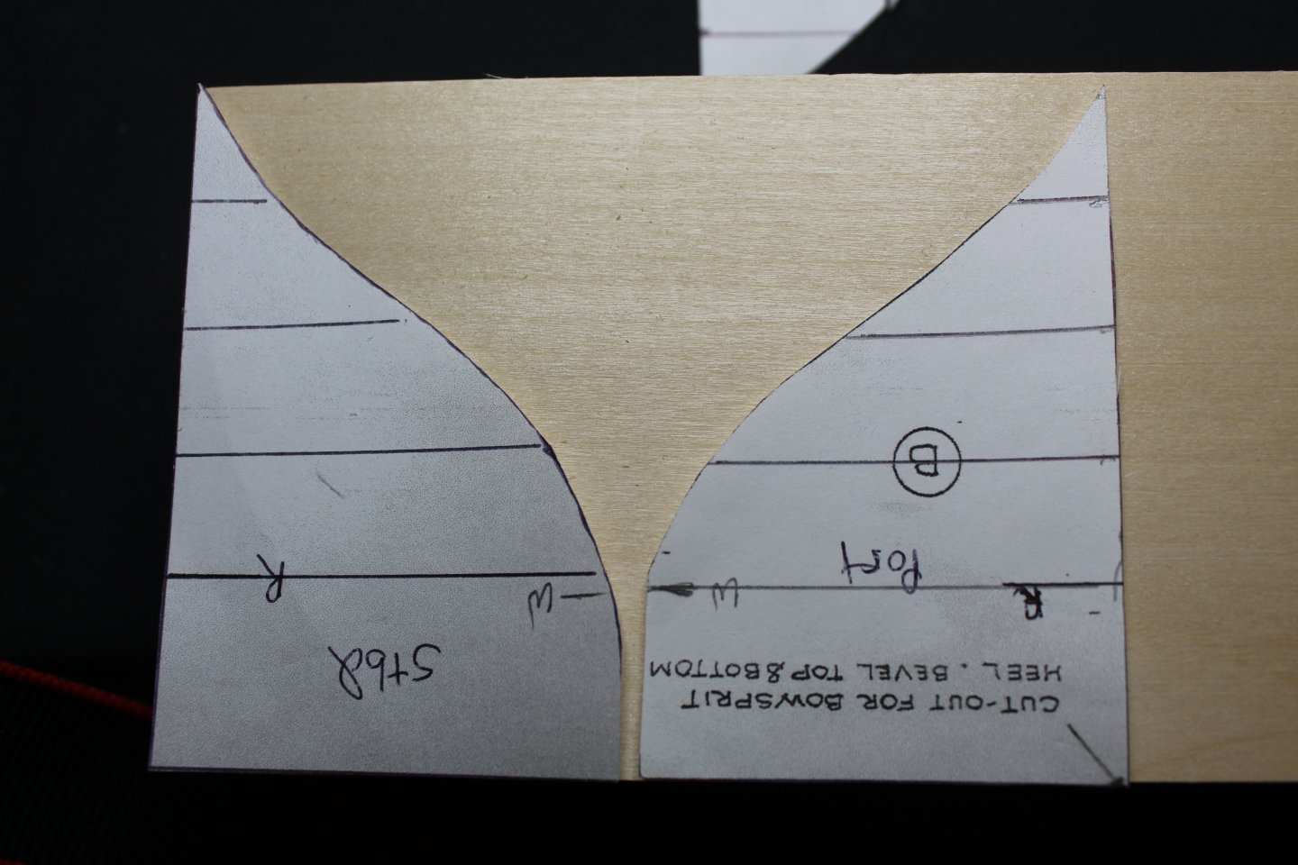
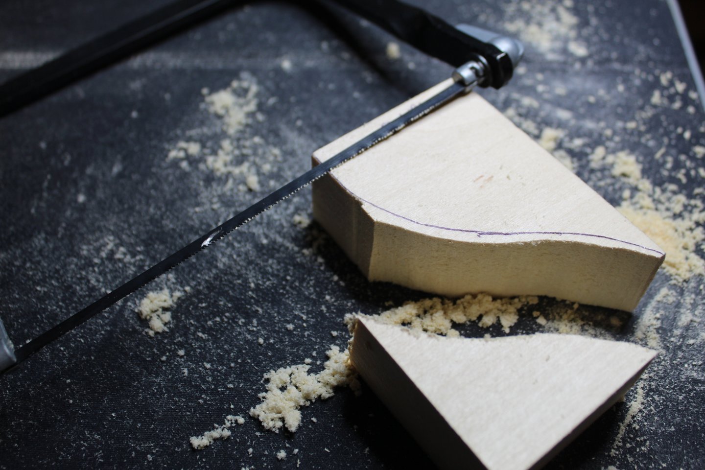
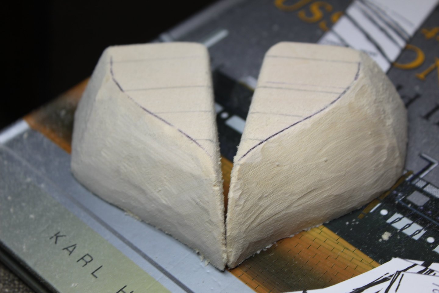
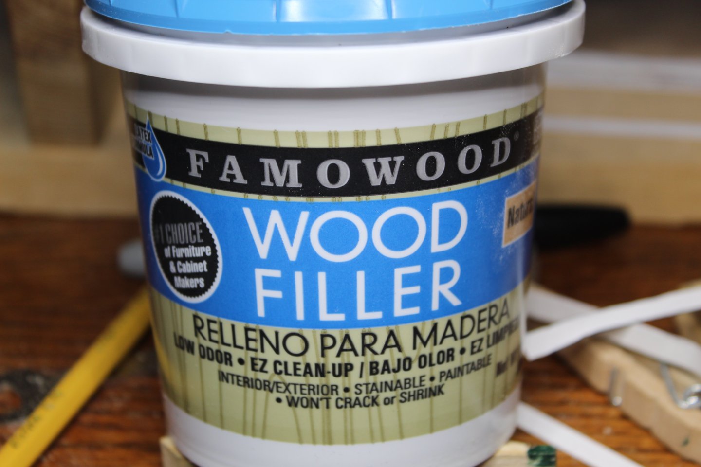
Over the last couple of weeks I looked into the A-B filler block shapes, laid them out on a block of basswood, and cut them out. I then shaped them using my rotary tool with a sanding fitting (yes, I do have one of these). Once shaped, I epoxied them into place. As you can see, I was a bit too aggressive in my sanding, but fortunately, I have found some great filler - it goes on really smoothly, and is easy to sand. I'm still not completely satisfied with the shape - there are some low spots I need to deal with. Still, I am happy that I took the time to add these - thanks for the prompting, Peter! The below image is from Anatomy of the Ship And here are extensions from the plans. Bulkhead A uses the untapered edge, while Bulkhead B uses the tapered edge. Happy Labor Day, Everyone!


-
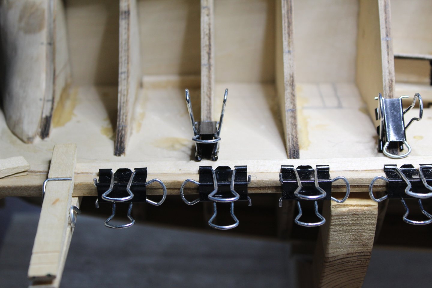
Hi Peter, Yes, the tape has already been removed from the hull. After I was satisfied with the look, I sliced up some tick strips and marked crossing locations on them. And on the filler blocks fore and aft I did my best to mark off the path of the tape. It gives me a good idea on how things should go. I've measured all of the tick strips and entered them into a spreadsheet to help with plank width planning. I will take these measurements and transfer them back to the bulkheads in marker. And of course, you are right - I do remember you and others mentioning something about how it would have been better to have filler blocks between A and B to reduce the flattening out of planks in that area. It'll be a challenge to make them now with the wales already in place, but I think I will go ahead and do it. Thanks for the suggestion! More to come.
-
Thank you sir! You sure have made a LOT of great progress in the last year! And regarding tools - on the larger scale, I have a policy that any new project deserves a new tool! But a full-size mitre saw, finishing nailer, impact driver, etc. have limited use in model ship building! And I would guess that the modeling size tools that look so handy would have limited use for the Admiral's full size re-modeling projects!
-
Just one more thing about the ladders, or gun carriages, or hatch coamings, or anything like that...find something that works, and then crank out all of them you need -- quick before you forget how you did it!! I just hope I can find them once I get to the point of needing the rest of them!
-
Thanks Mustafa, Tim, and Jon! @mtbediz, for sure I'll add you to the watch list. @JSGerson, it was all the trouble you had with the handholds coming loose that makes me want to wait until the hull is planked, the gun deck is completely detailed, and I'm ready to enclose it with the spar deck before adding it. I swear, the littlest thing, like crooked stair treads will derail me for the longest time. And I don't want to invest in expensive tools that I may or may not use again once this is done. I admire how some of you folks say, "so let's go to the drill press/lathe/table saw/etc. and whip up thus and such". Sounds great, but oh, so expensive!!! (But oooooh so nice!!!). We'll see what the Admiral says about adding to my tool collection! Thanks all for the likes, and I'll be updating with planking posts soon! WAY sooner than another year!
-
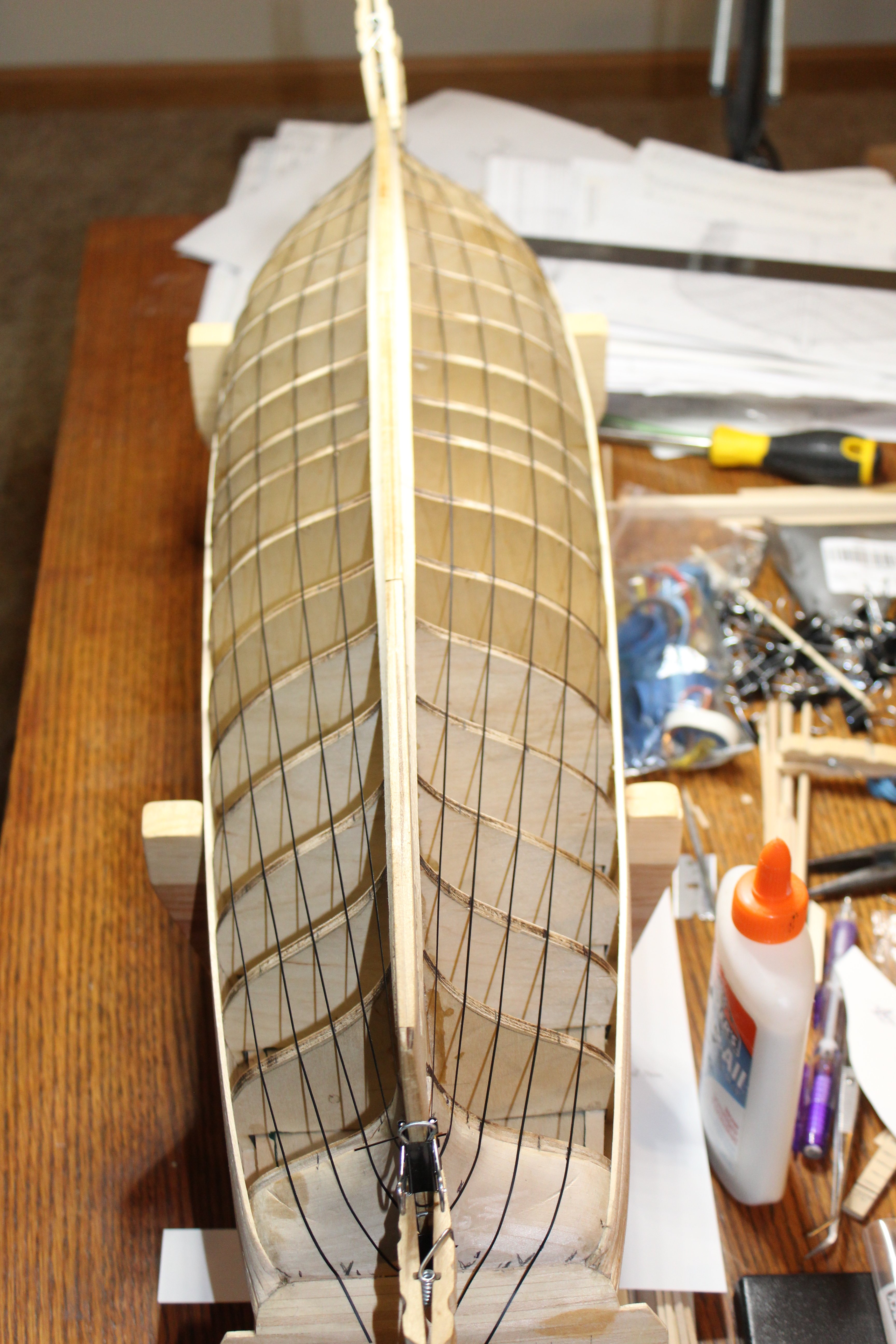
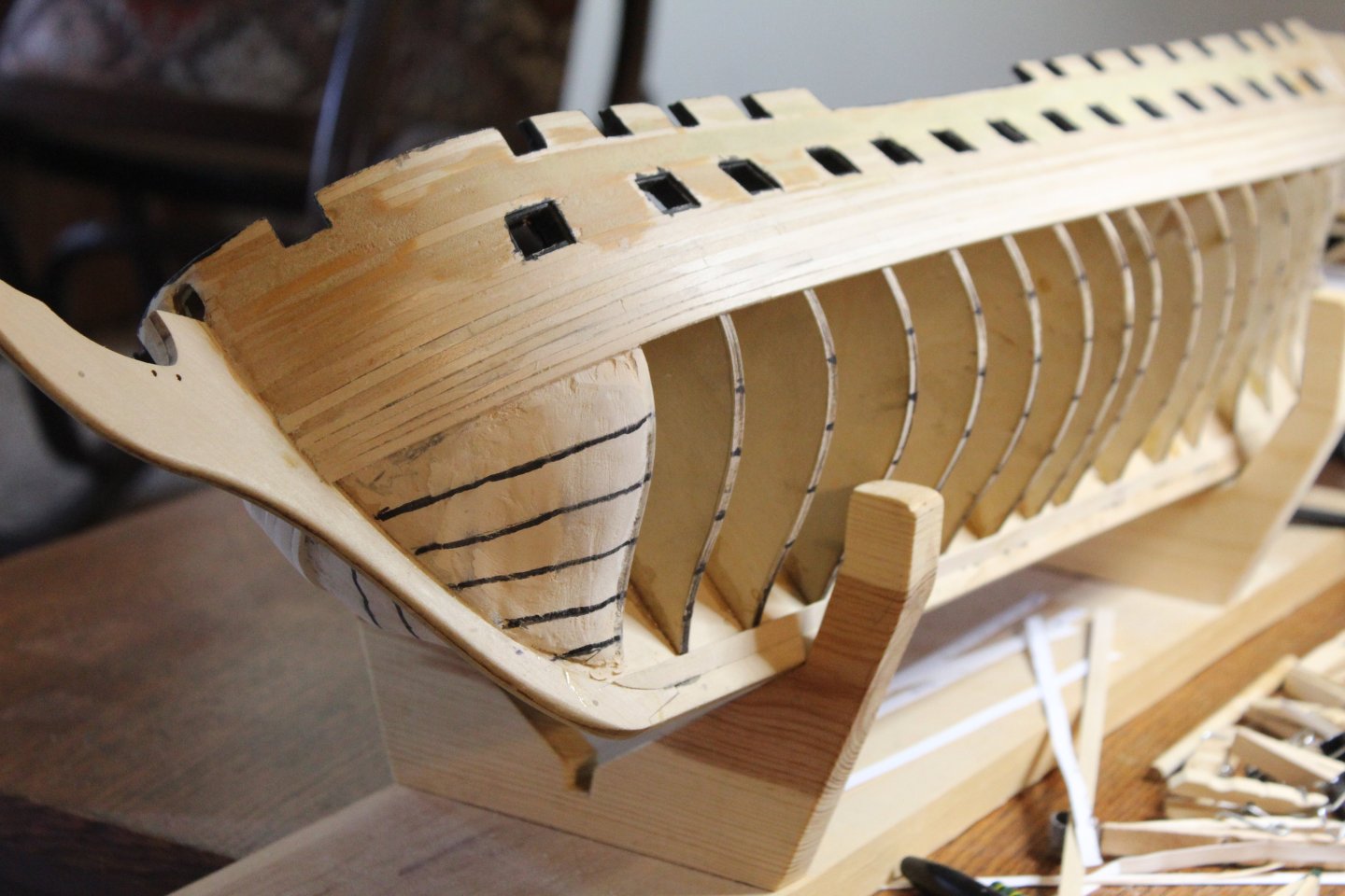
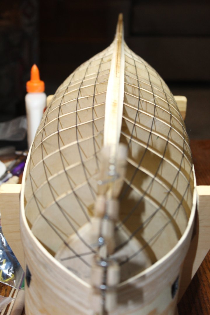
Next, I planked the wales and added the garboard strake. Sorry I didn't take any photos of planking the wales. Just recently I lined off the hull. This is a new thing for me, and I'm sure it's not perfect. Still, it gives me a good idea how the planking bands will go. (almost has the look of a dirigible w/o skin on 😊) I’ll try to update this build a bit more often than once a year from now on! On to planking!!

-
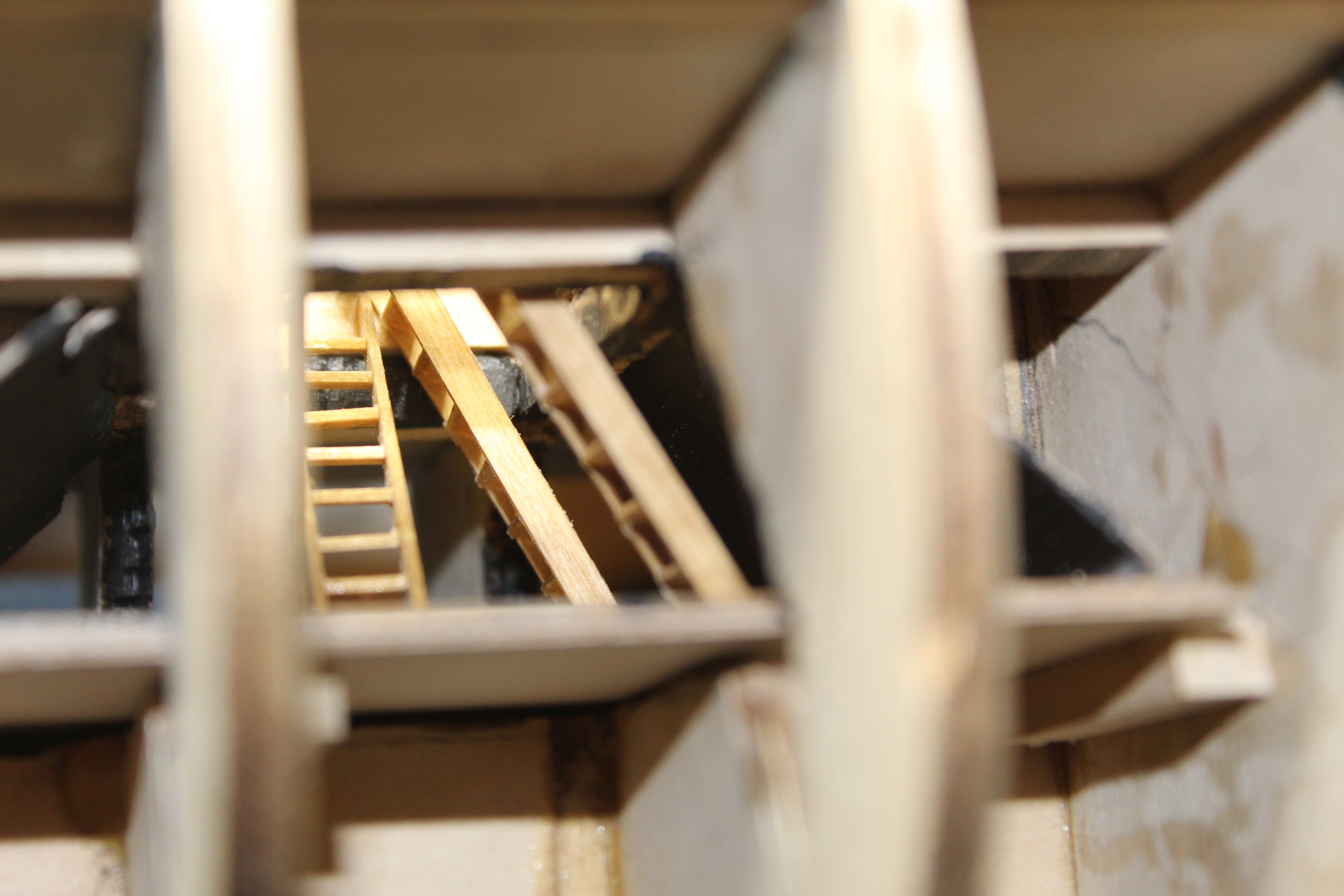
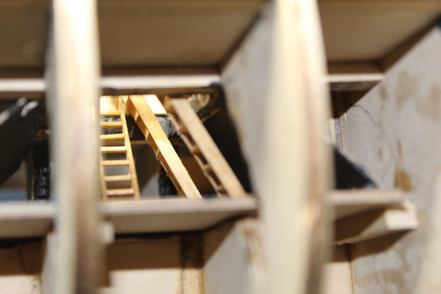
I mounted the ladders between the Berth and Gun Decks, and chose – at least at this time – to leave off the handholds. I will re-visit them once I begin detailing the Gun Deck.. Once all the ladders were mounted, I enclosed the Berth Deck with some spare 1/32” ply that I had, painted black on inside facing.

-
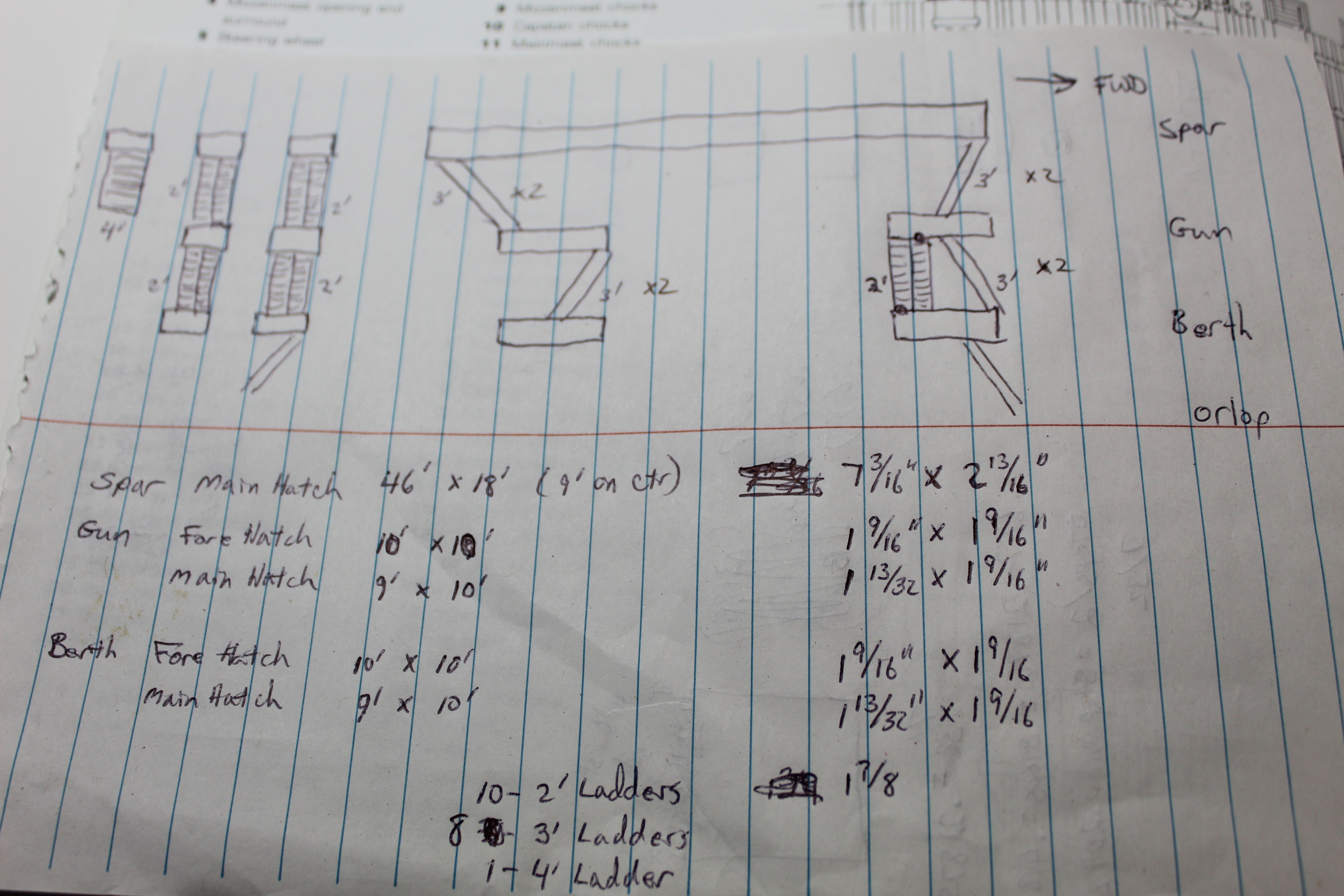
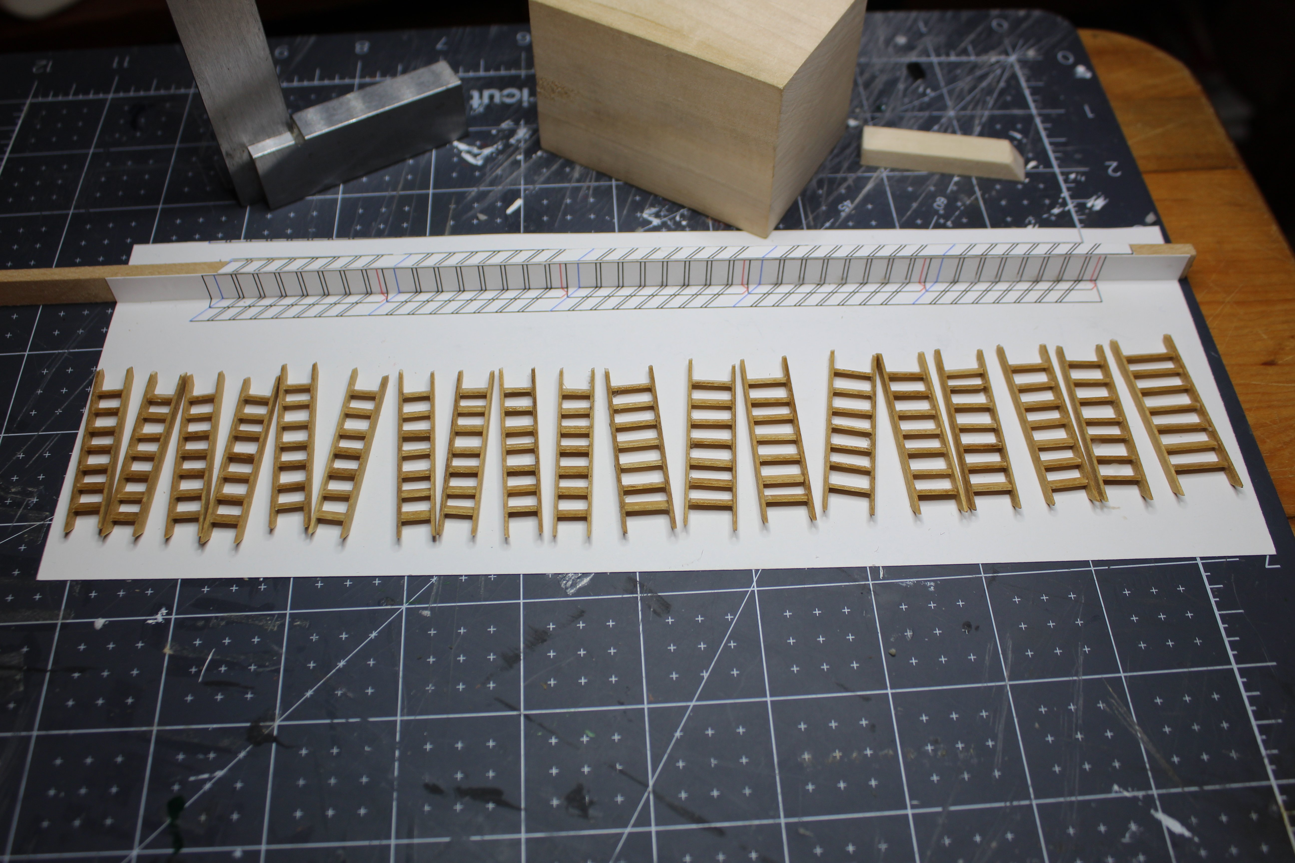
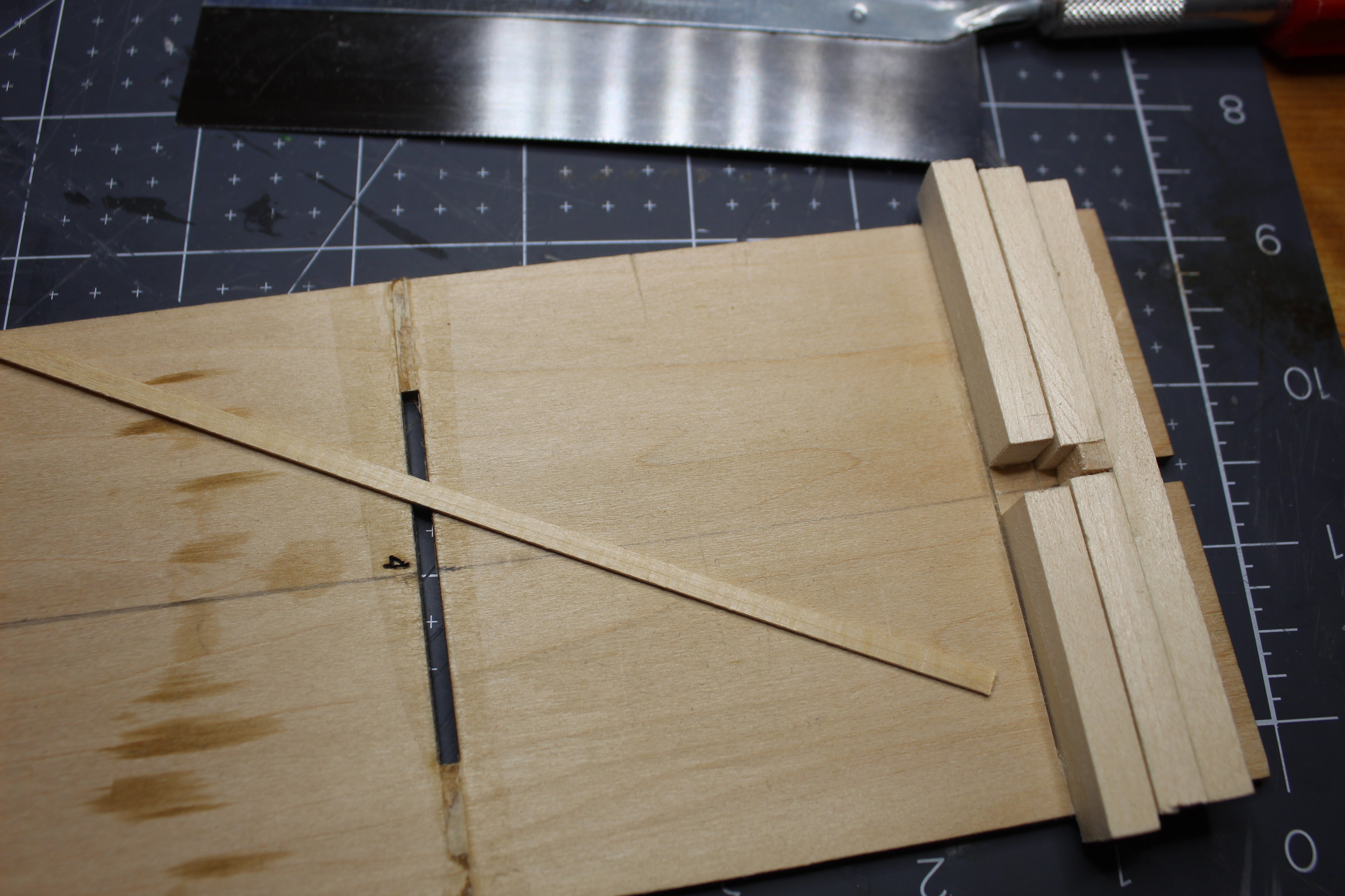
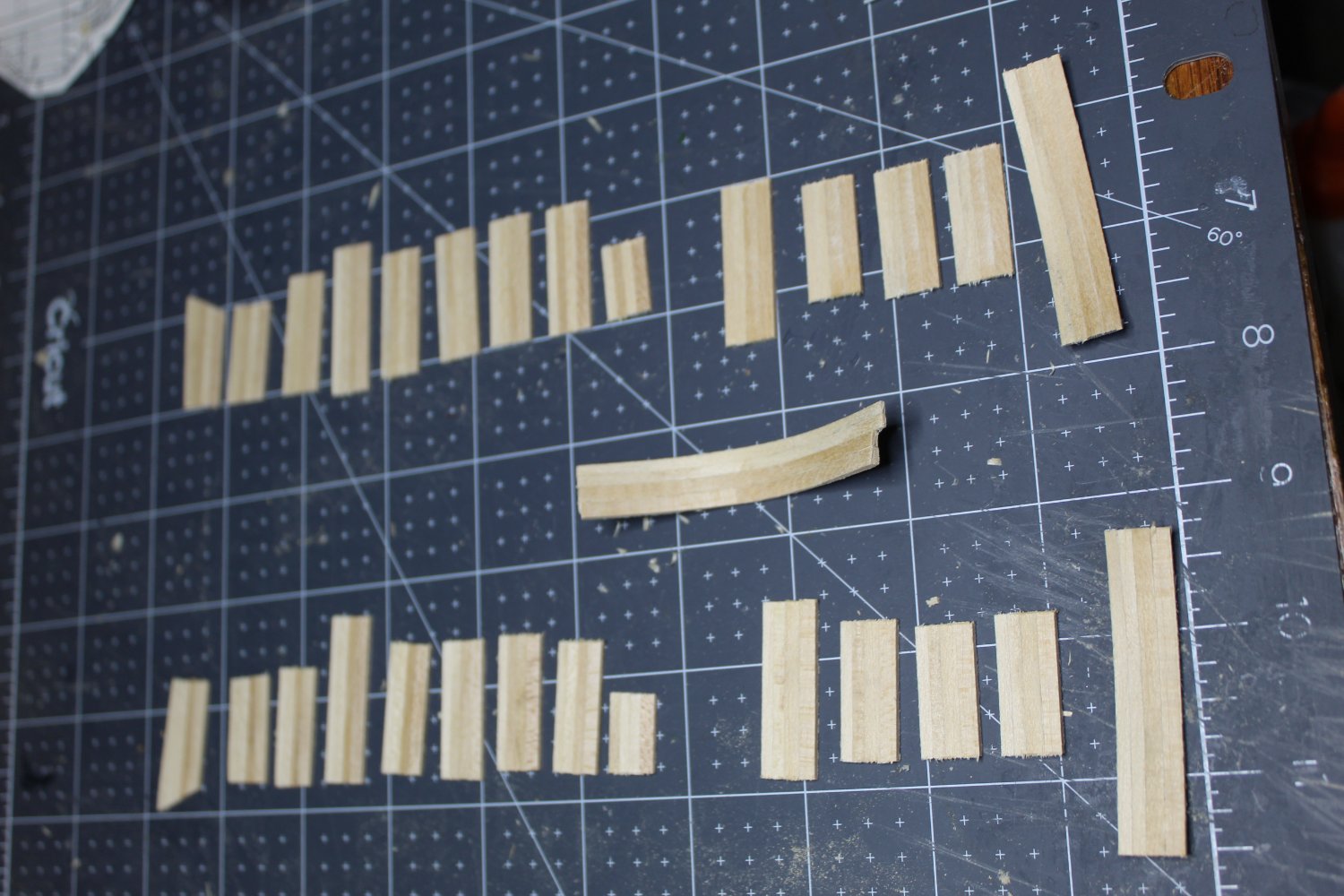
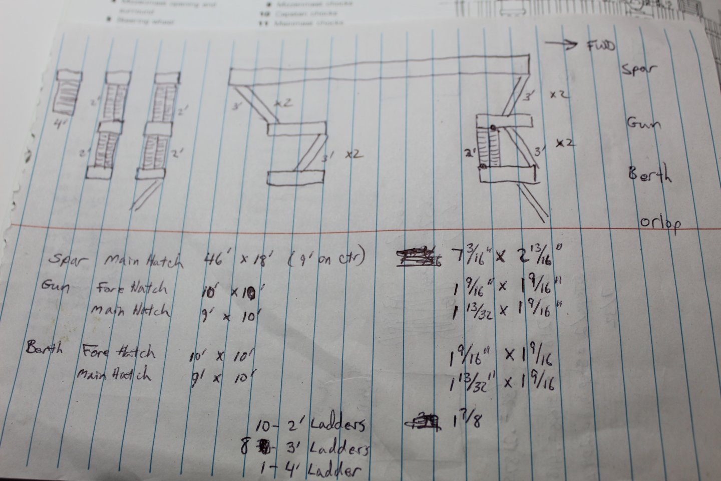
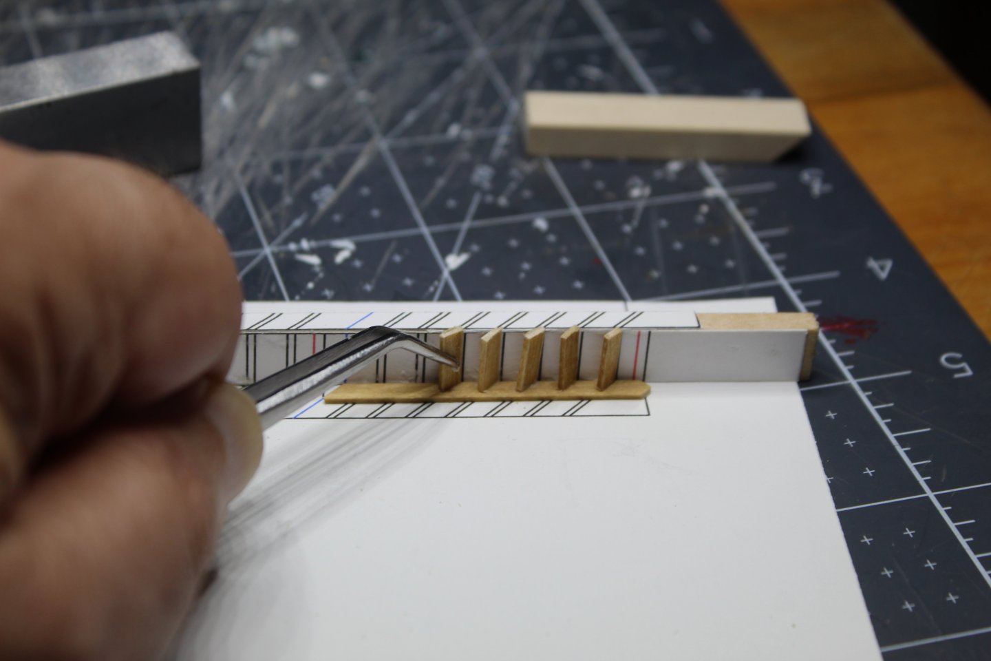
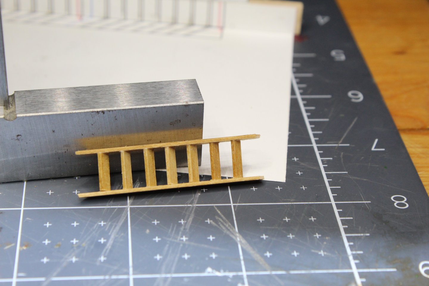
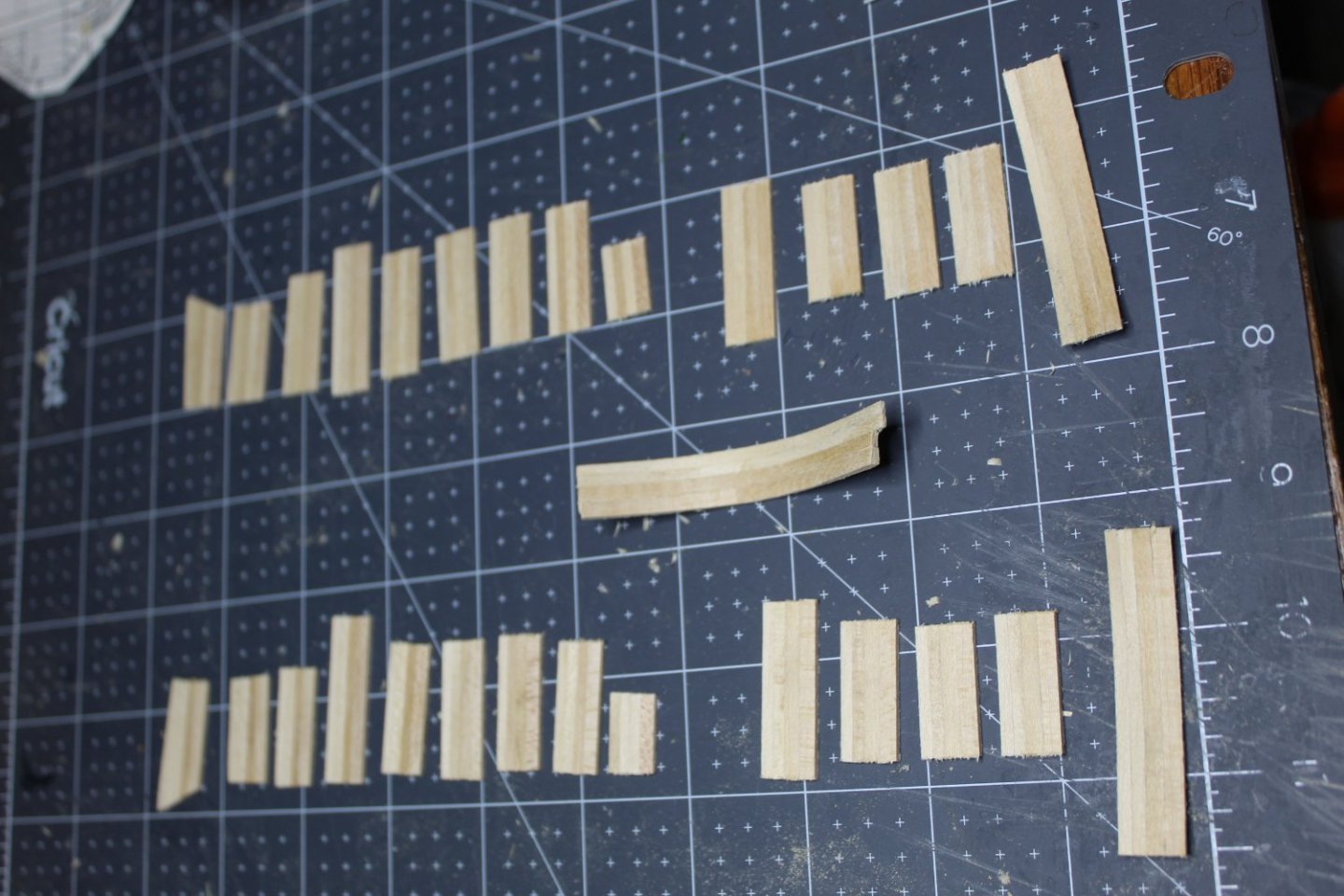
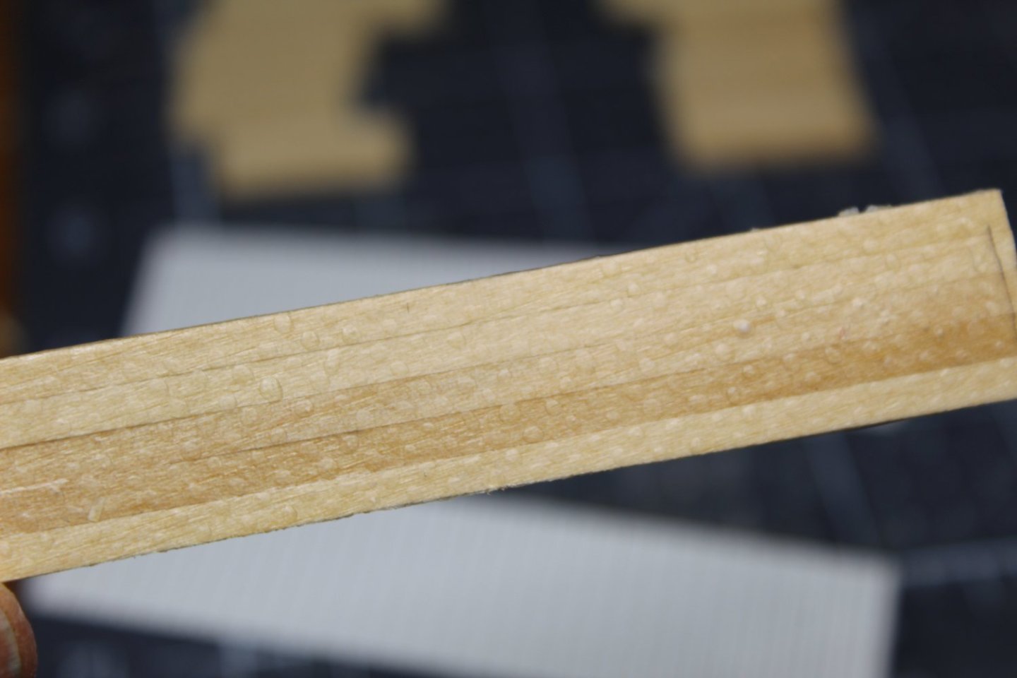
Once I had the technique down, I went ahead and created all ladders that I will need for Connie. I based this on reference drawings from AOTS, both for number of ladders and their widths. From that, I got 10-2’ ladders, 8-3’ ladders, and 1-4’ ladder. Below is the sketch I made of the layout. I cut all of the stair treads using the below jig. In the photo, I added a spacer in order to cut the 3 foot treads. Prior to the spacer being added, I cut all of the 2 foot treads using the slot between the blocks. I was pleased how nice and square the treads turned out (I DO have a miter box for my razor saw, but it’s poor quality, and leaves much to be desired). The resultant ladders are below, and while not perfect, they are good enough for me.


-
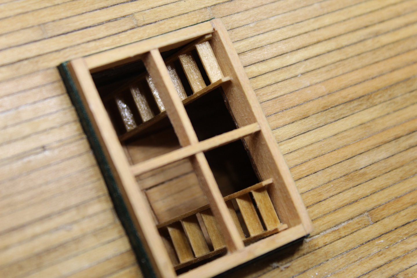
Time for an update. Last October, I realized that detailing the Gun Deck was probably a bad idea before the hull was planked, due to all of the upside-down and turnings of the hull while doing planking and the likelihood that deck details would probably start to come apart. So on to planking the hull! But then I realized – before I planked the hull, I needed to get the Berth Deck enclosed (to keep dust/debris out, etc). And before I could do that, I needed to build ladders from the Gun Deck to the Berth Deck. I began working on ladders last spring, and that presented problems for me. Every which way I tried, I was dissatisfied with the outcome. Treads were obviously crooked, etc. In May, I finally came up with this: Note that while some of the treads are a little crooked in the above photo, it was easy enough to see and adjust or completely remove and re-set before the glue set. This resulted in a ladder that looked like this: I was quite happy with the result.
-
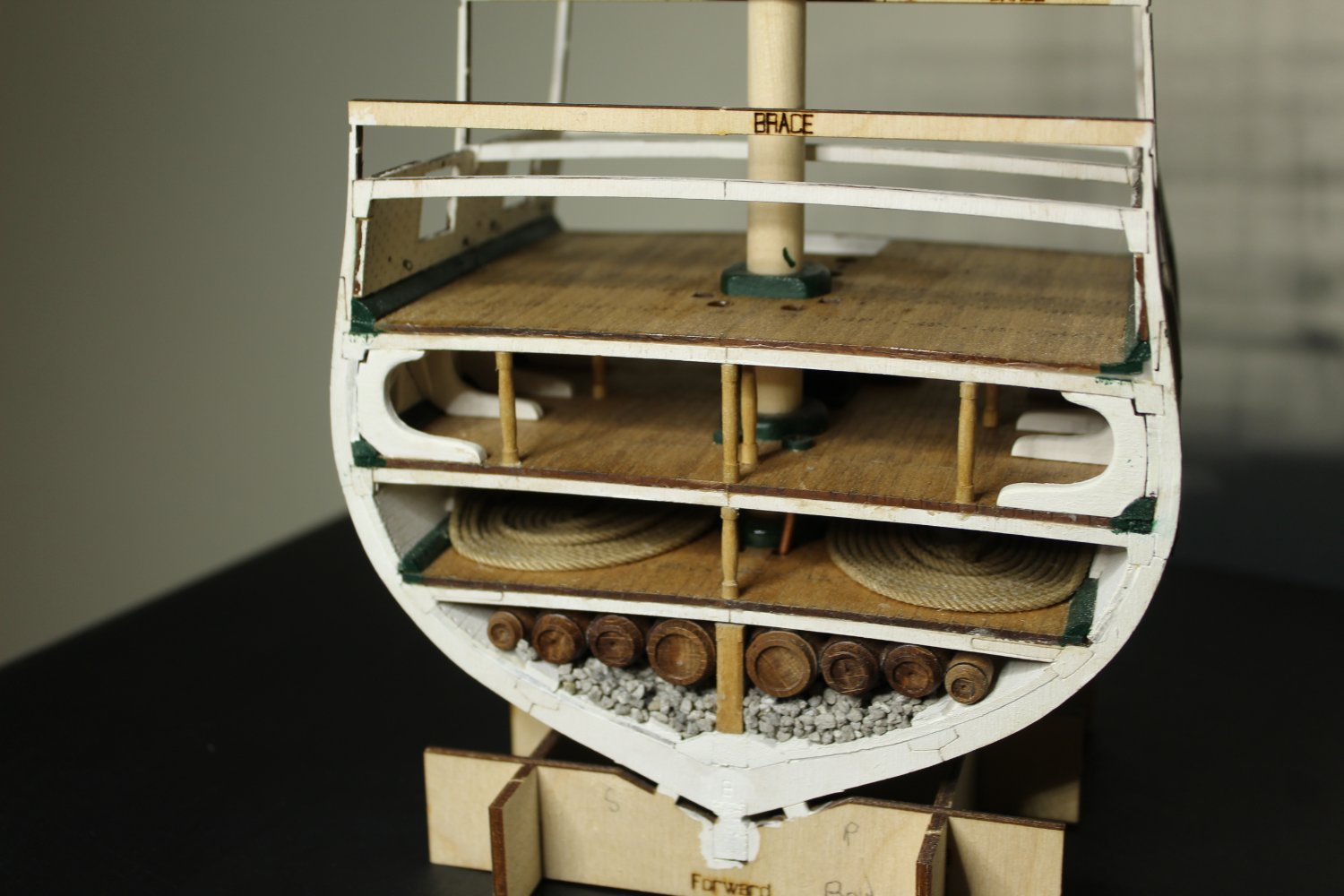
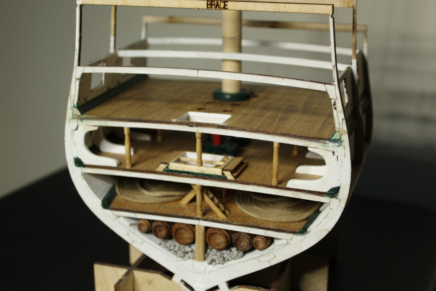
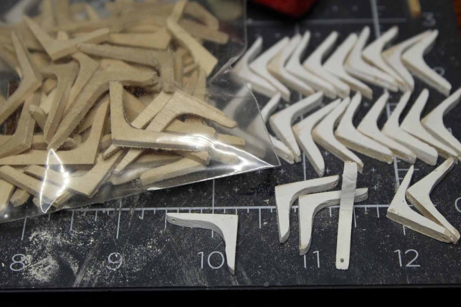
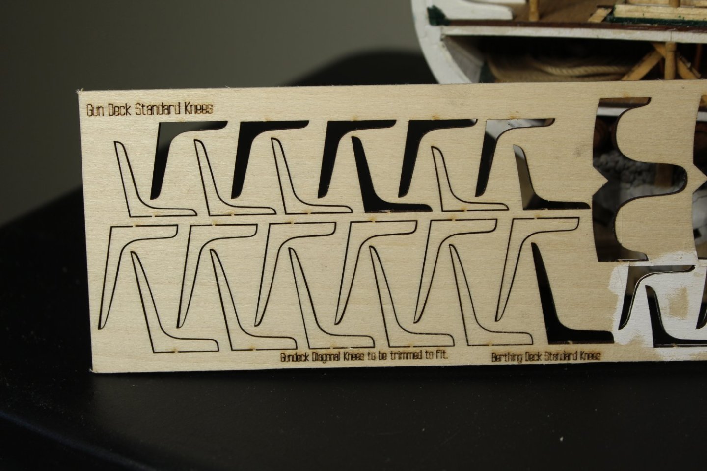
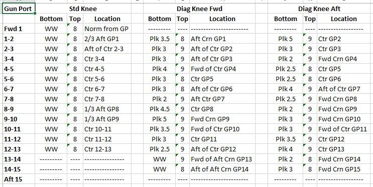
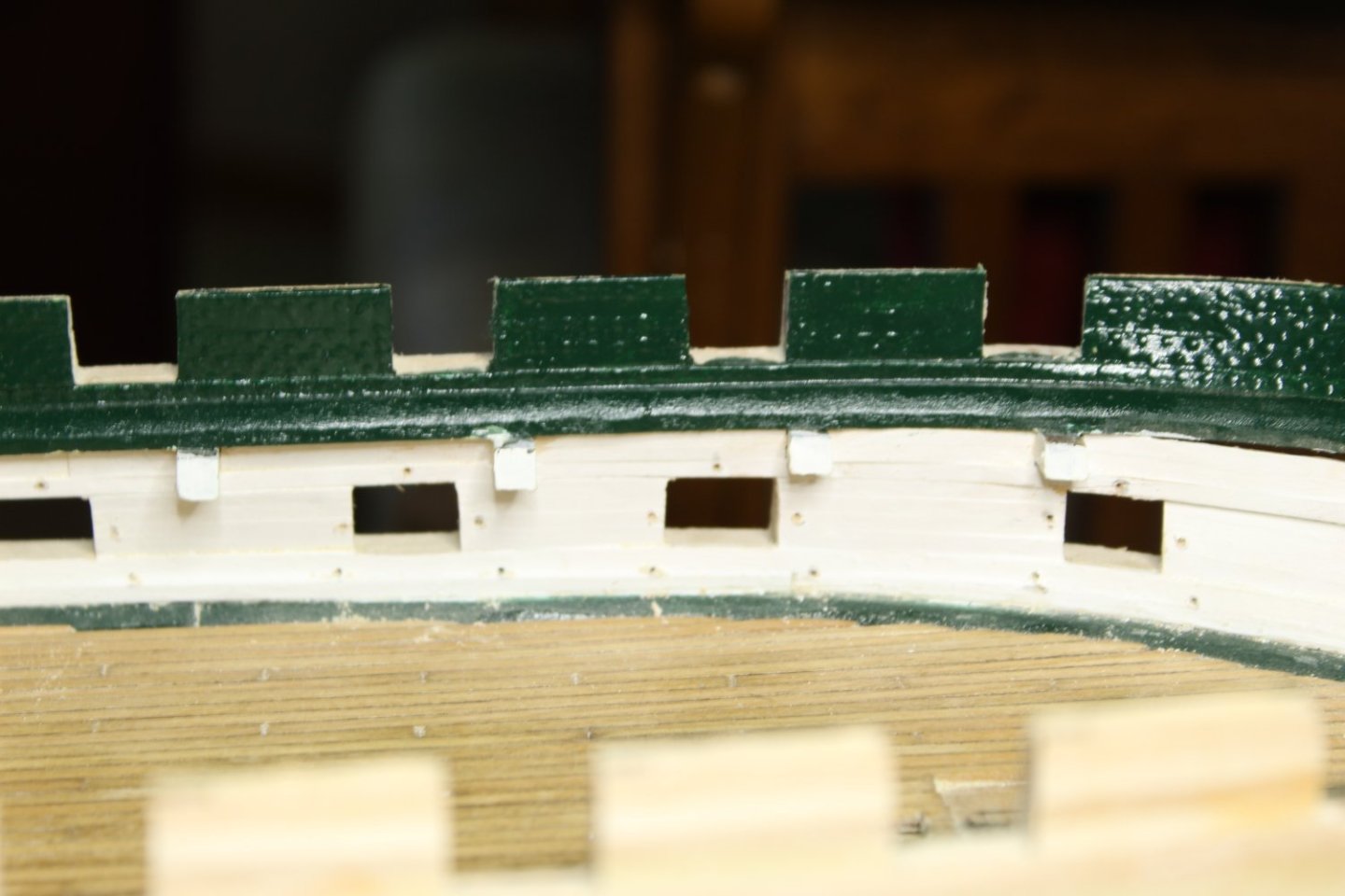
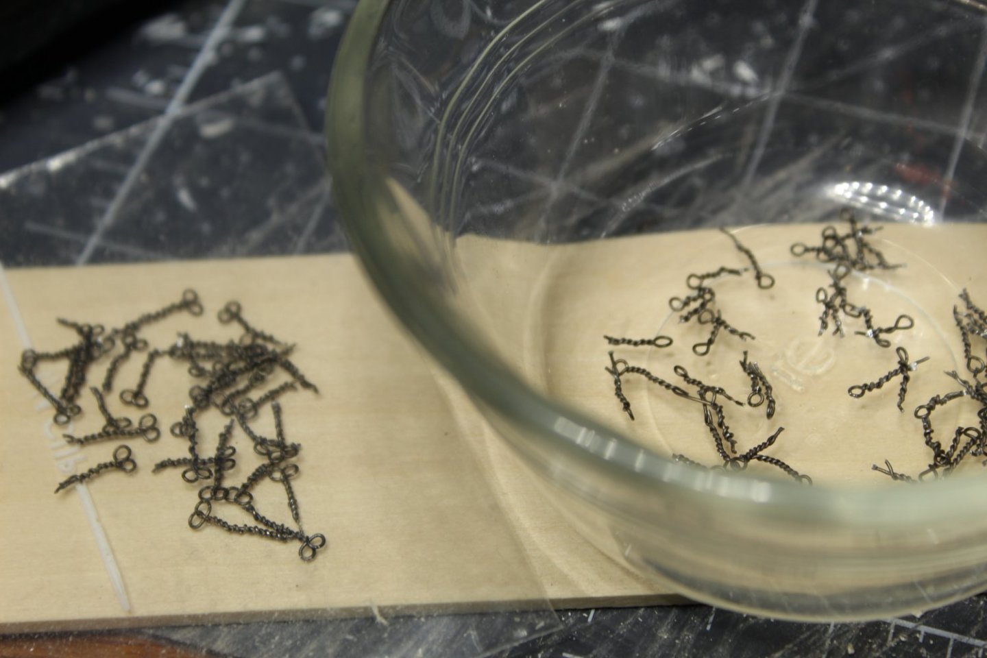
Ok, here we go. In this almost-year away, I've been busy MOSTLY away from the shipyard. However, I did work a little bit and here is what I was working on: I wasn't interested in creating a build log - it was more for a build along-side the full ship. I'm interested in displaying this alongside the full ship to show what things look like below decks. I only plan on finishing the main mast up to the fighting top and leaving the yardarm off. I was also interested in how things were done on the gun deck on this model. Something I got from it was the knees: I traced these and cut them out with a razor saw. Once the basic shape was done, I used a rotary tool with a sander on it to clean them up - here is the results: I used the google maps view of the gun deck to check out the knee placement, and came up with the following table. The bottom and tops are the plank numbers measured from the waterway: Just the other night I drilled the holes around the gun ports, and began manufacturing eyes: That's it for now. I'll be mounting the eyes around the ports next, then putting in the knees.


-
Thanks folks. I can really relate to both of you. Reminds me of back in the 80s when I was finishing my basement, and I'd go down there and just sit and stare at things wondering, "now what the heck am I going to do about that...". It eventually worked itself out, but it really derails you for a time. Anyway, I'm back on track for now, and it feels good to be back.
-
Hi All, Sorry for the REALLY long break, but I needed it. I'm getting back to the shipyard, now that the leaves are beginning to fall (helped by the dry weather conditions here). I've been working on the gun deck knees and will include pics shortly. Welcome Der Alte Rentner! Sorry that you picked a slow time in the shipyard to join in! Hopefully there'll be something for you to see soon. My plans moving forward (at least for now) is to finish up the knees, continue planking the hull, and in between things, I'll begin fabricating the gun deck furnishings, including the ship's stove, capstan, etc.
-
Very nice gun carriages Jon! I'll be getting back to the shipyard soon, and will be referencing your build again. Bob
-
Hi JJ - I wish I could take credit for this, but there are far smarter people on this site than me! I'm just replicating what I've already seen here on MSW.
-
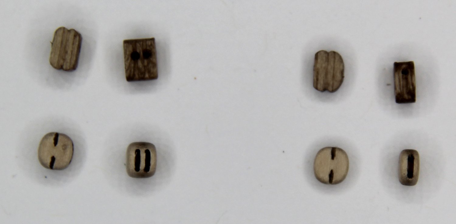
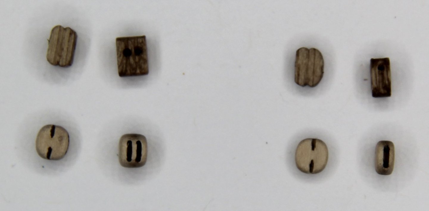
Here's just a quick follow-up from my previous post about blocks. The picture below shows 1/8" single and double blocks that came with the kit, and below them the blocks I purchased from Syren Ship Model Company. The Siren blocks have 2 holes in each of the sheave slots and are over all better in my opinion. (The strange halo effect is because my ring light is only a few inches directly overhead, and I'm shooting thru the magnifier). The coloring is more a medium-brown on the MS blocks, and a yellowish-tan for the Syren blocks.
-
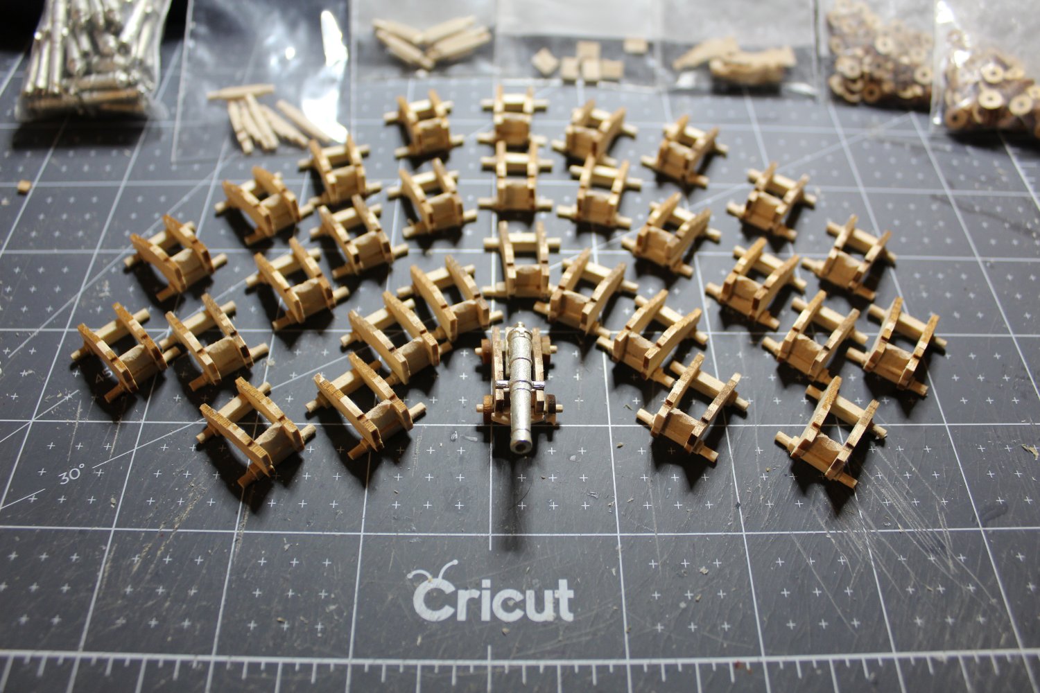
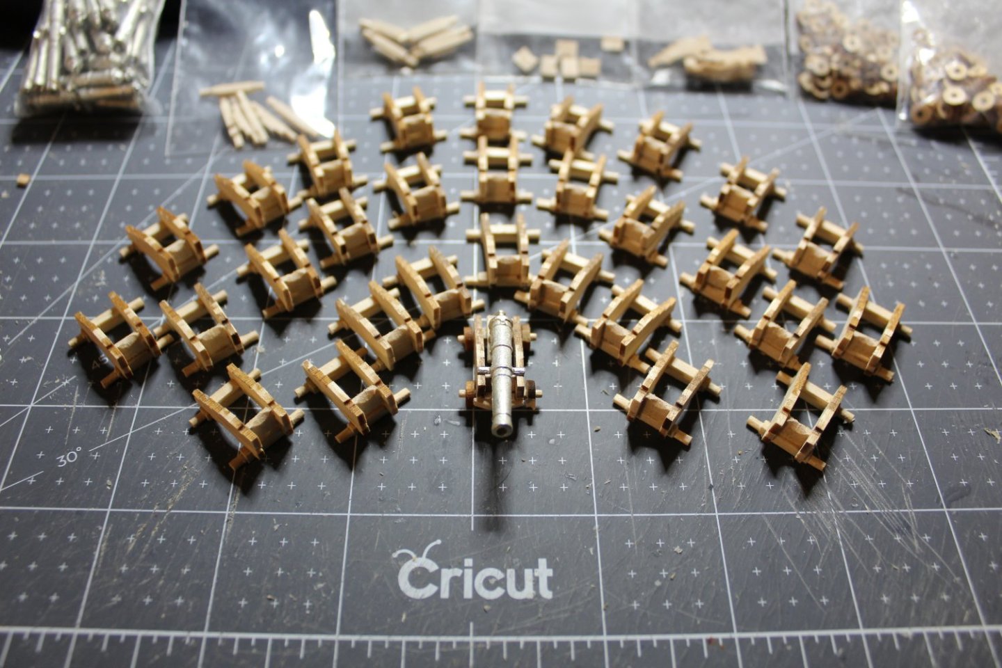
Next up: The Gun Carriages. These took a few weeks prep. I already had added the 1/16” filler to the carriage sides. I needed to make the parts – front axle, rear axle, etc. You can see all of the parts on my Jan 29th post. I made 35 of each, just to make sure of 30 good ones. Once all of the parts were made, I assembled the carriages. Now all I need is to find the right paint color. What colors have you all used for this, or was it a custom mixture? For the gun tackles, I purchased blocks from Chuck P’s Syren Ship Model Company. I just wanted to mention this, because the blocks are spectacular! Makes me want to replace all of the kit’s blocks with Chuck’s, but it’ll cost a lot to do this – they are reasonably priced, but there are so many of them on Constitution. And no, Chuck is NOT paying me for this advertisement! I’m a long way from rigging, so I might start replacing them a little at a time. In the meantime, I’ll be making the gun tackles when I’m closer to installing the guns, probably AFTER the hull is completely planked. I wish you all a wonderful Thanksgiving Holiday. I have many things to be thankful for and will be counting my blessings on Thursday along with many of you. Fair winds, Bob

-
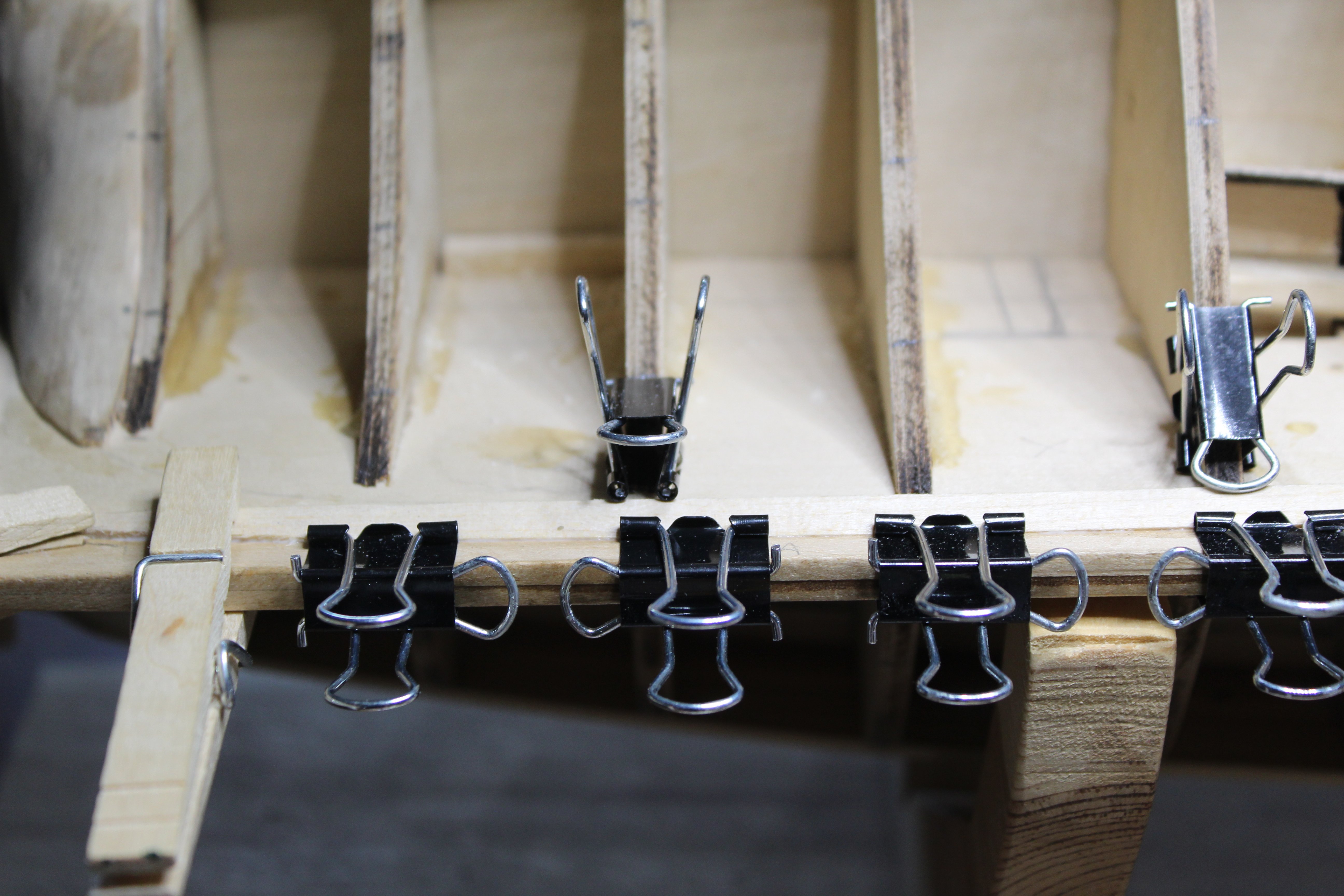
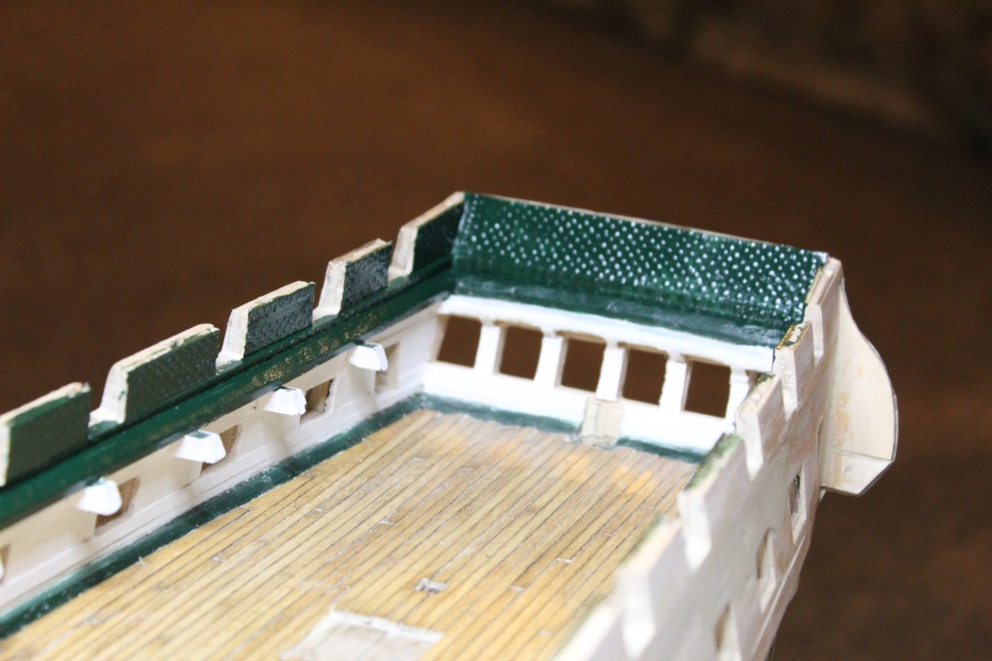
Hi all, thanks for the likes! I really appreciate it, and it encourages me to keep going. With Thanksgiving approaching and family coming over, the Admiral said it was time to shut down the shipyard and make it ship-shape for our guests and safe for the grandkids. Now that I’ve done that, it’s a good time to update the build log. In my last entry, I was going to clean things up on the outer planking and then begin the wales. I DID begin cleaning up the planking, and filling where necessary, but every time I filled and sanded, there were more places I needed to fill and sand. I got frustrated and decided to move to something different for a while. So, on to the bulwarks! I decided to go with the “glue-drop method” of adding the rivets/bolts. I admire the workmanship, and the patience that some of you have gone to in order to make these look more realistic. However, I couldn’t envision spending the next 10 years punching out tiny brass rivet heads (and losing them). Likewise, the thought of drilling tiny holes and going crazy trying to insert tiny plastic rivets was not my cup of tea! So, glue dots it was. First, I made the bulwarks by edge-gluing the planks. For the curved bow section, I soaked the planks, and clamped to the frames to set the curve. I edge glued these as well once they were dry. This didn’t work out as well as I had hoped, because I glued these “on-edge” vs stair-stepped as they probably were when they were wet on the frames. So, I repeated the process, but once dry, I glued the planks to the frames with the intention of adding glue dots to these curved sections on the hull. I did a test application on a mock-up panel. The rivets were difficult to see once dry, but under magnification I noticed that the glue had flattened out too much. Then I did another mock-up panel and applied 3 coats of varnish prior to applying the glue dots. The rivets were much better defined this way. I sanded / varnished all of the panels in a likewise manner. I then sharpened a bunch of toothpicks to apply the glue dots. I applied to one panel and let it dry. I was happy with the results – but then realized that this panel, as well as most of the other panels would have pin rails attached later, and the “rivets” would get in the way. I tried to remove the rivets in the pin rail area and found that they were quite easy – almost too easy – to remove with a simple knife tip scrape. That worried me, that I would knock them off in handling. So as soon as possible, I decided I would paint them. I identified which panels would have pin rails and avoided this area while applying glue dots to all of the remaining panels. I had to keep switching toothpicks as the glue quickly built up on them and had to keep refreshing the glue puddle I was dipping into as it dried/thickened fairly quickly. Under magnification there were some dots that were a bit flat and needed to have extra glue added to define the dots. There were others that needed to be scraped away and redone completely. Once done, I attached the panels to the ship’s frames and added glue dots to the inner planksheer. Then I painted them all. The bulwarks are not as shiny as they look in the photos under bright light. Overall, I am happy with the results. Much better than nothing – it would have looked wrong – and much easier/faster than other techniques.

-
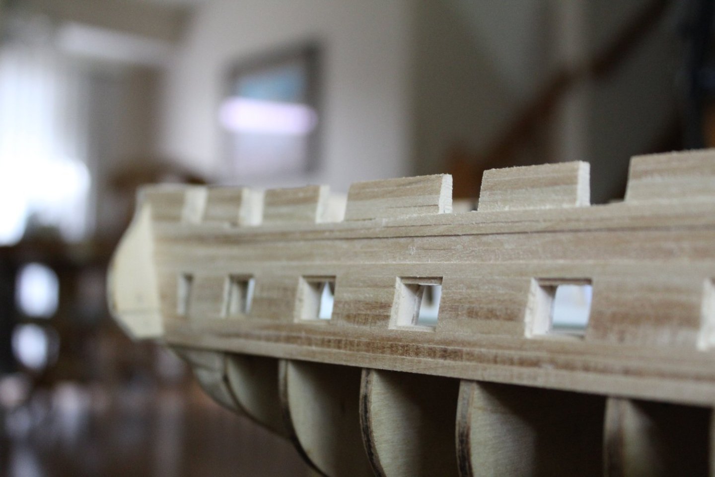
Finally, I decided that I needed to focus on a nice line, and for that, I would use long planks vs short ones. This would minimize all the joints, and the bumpiness I was running into because of them. I also decided that if necessary, I could sand down the planksheer to an even thickness with the rest of the planking, and add a thin planksheer on top of the planking – or not (we’ll see). With those decisions made, I went ahead and began laying planks, and here is where I am at present: Now I need to smooth out the surface, perhaps use some filler where necessary, and clean up gun port and stern window openings. Then I can begin to lay the wales. It's nice to be back in the shipyard, although I think that I'll be making it more of a HOBBY. You're sure welcome to join along - just don't get frustrated with long gaps between posts. I DO want to see this project finished someday, but not at the expense of my sanity . Fair winds to you all! - Bob


-
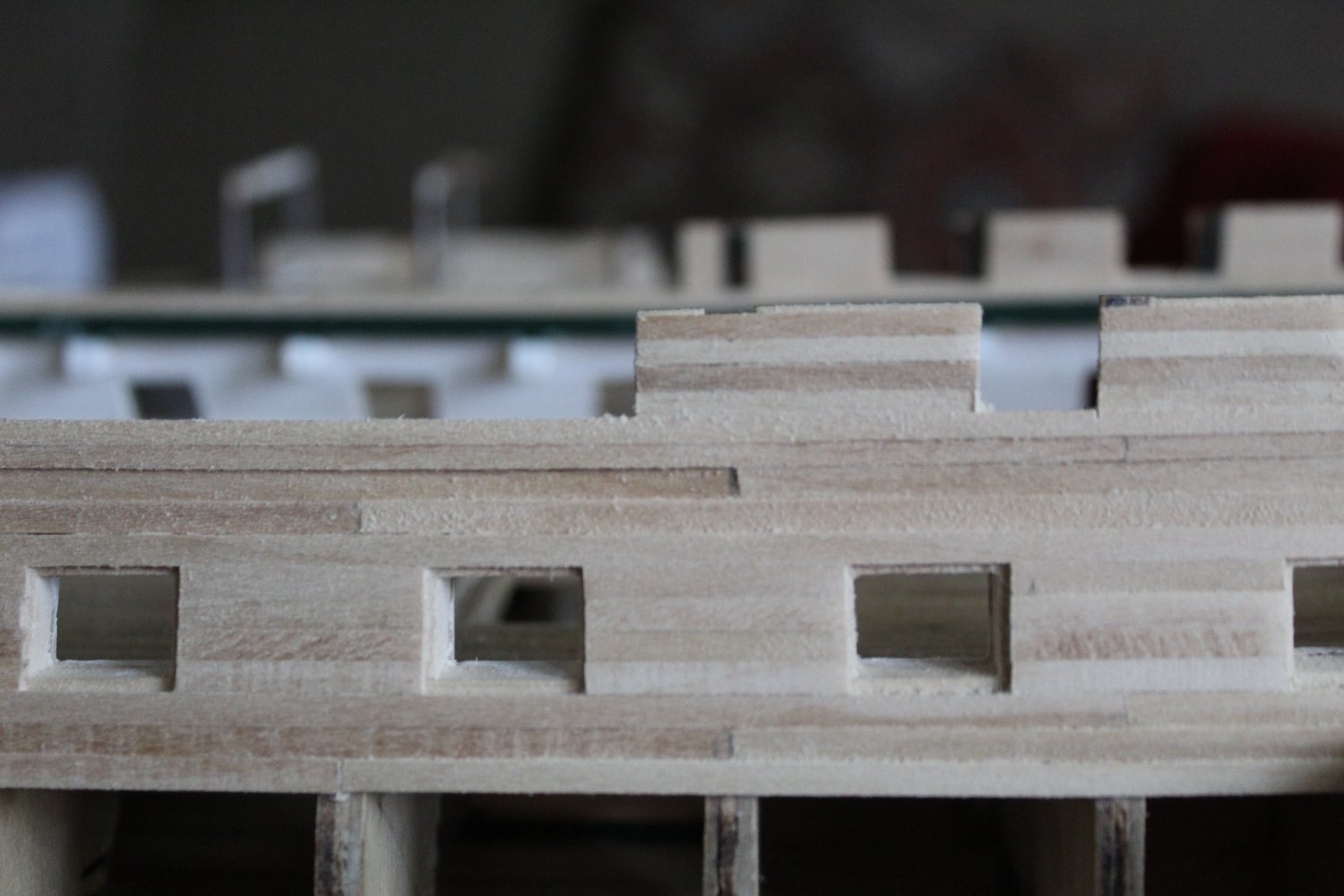
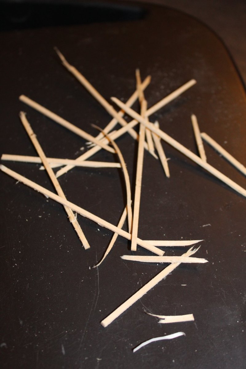
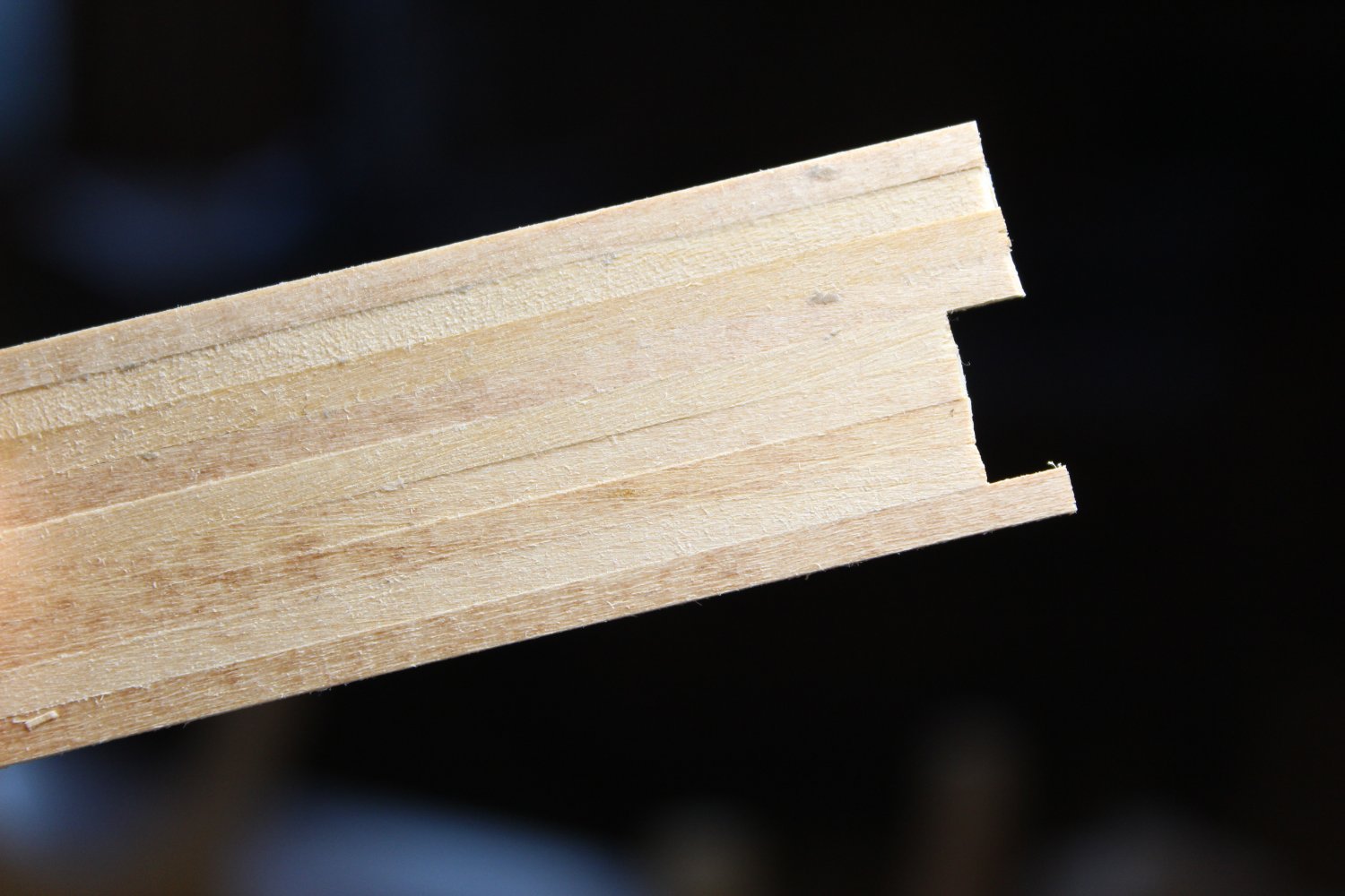
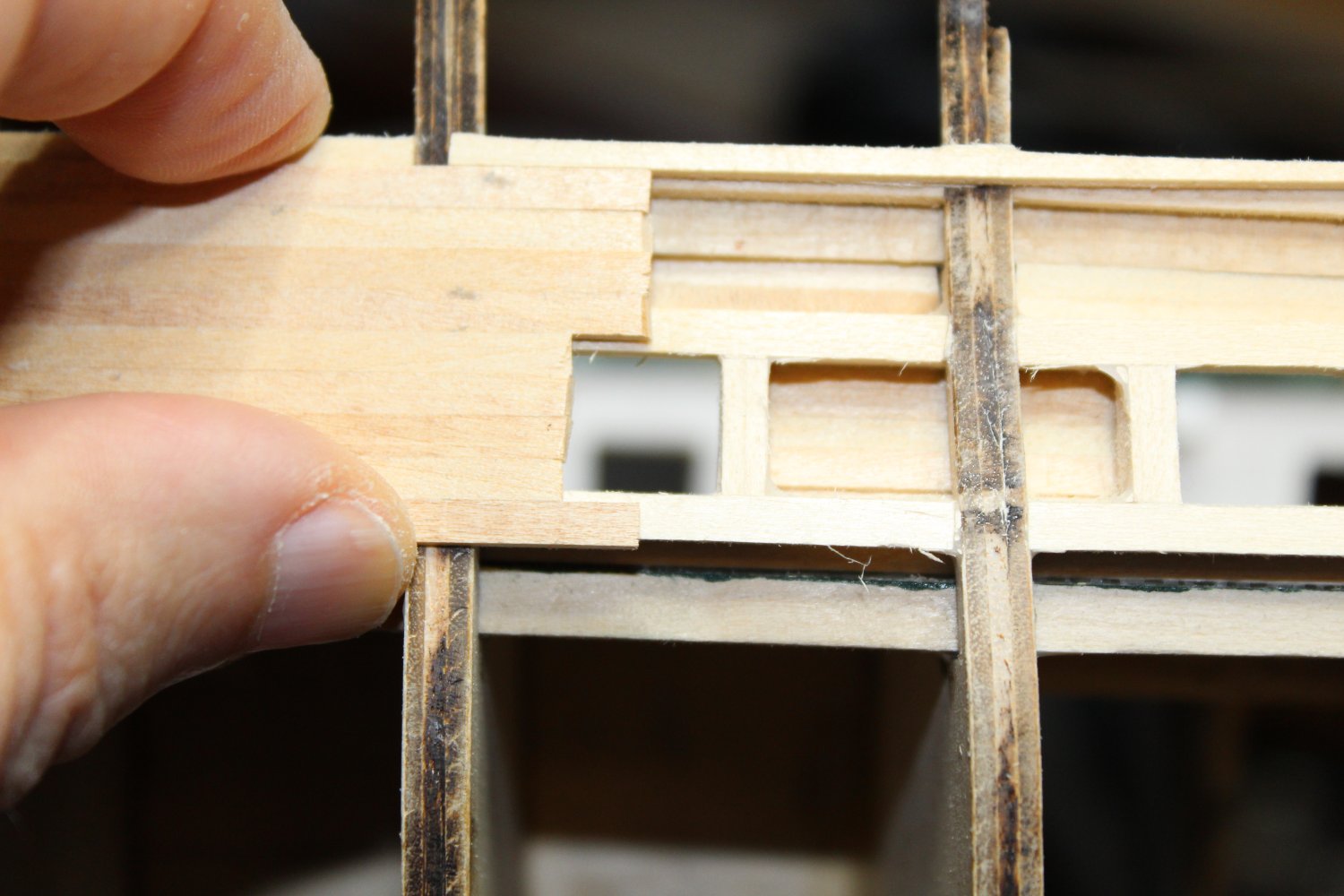
Thank you all for your likes, and welcome. Sorry for my silence over the last 6 months. I ran into an issue, and rather than ask a community of skilled modelers how to address the problem, I just tried figuring it out myself. I'm sure that you all would have had some great advice on how to proceed. The problem I ran into was the outer planksheer. My first attempt ended up with a wavy line from bow to stern. It ended like below: Then I made a tool to help with consistency - the notch is for the gun port: Unfortunately, while the bottom of the planksheer was a more uniform distance from the gun ports, the result was a planksheer with varying thicknesses, sometimes to so thin as to be almost non-existent: This ended up with a similar pile of sticks as the first.


-
Hi K-mart! Glad to see you back. I love how you did the stern windows. When I get there, I'll try using the same technique. -Bob
-
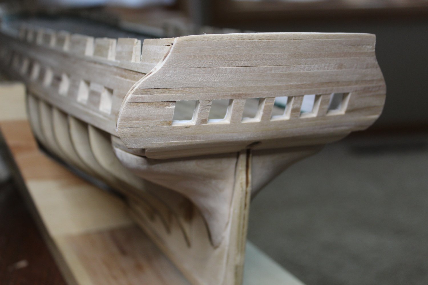
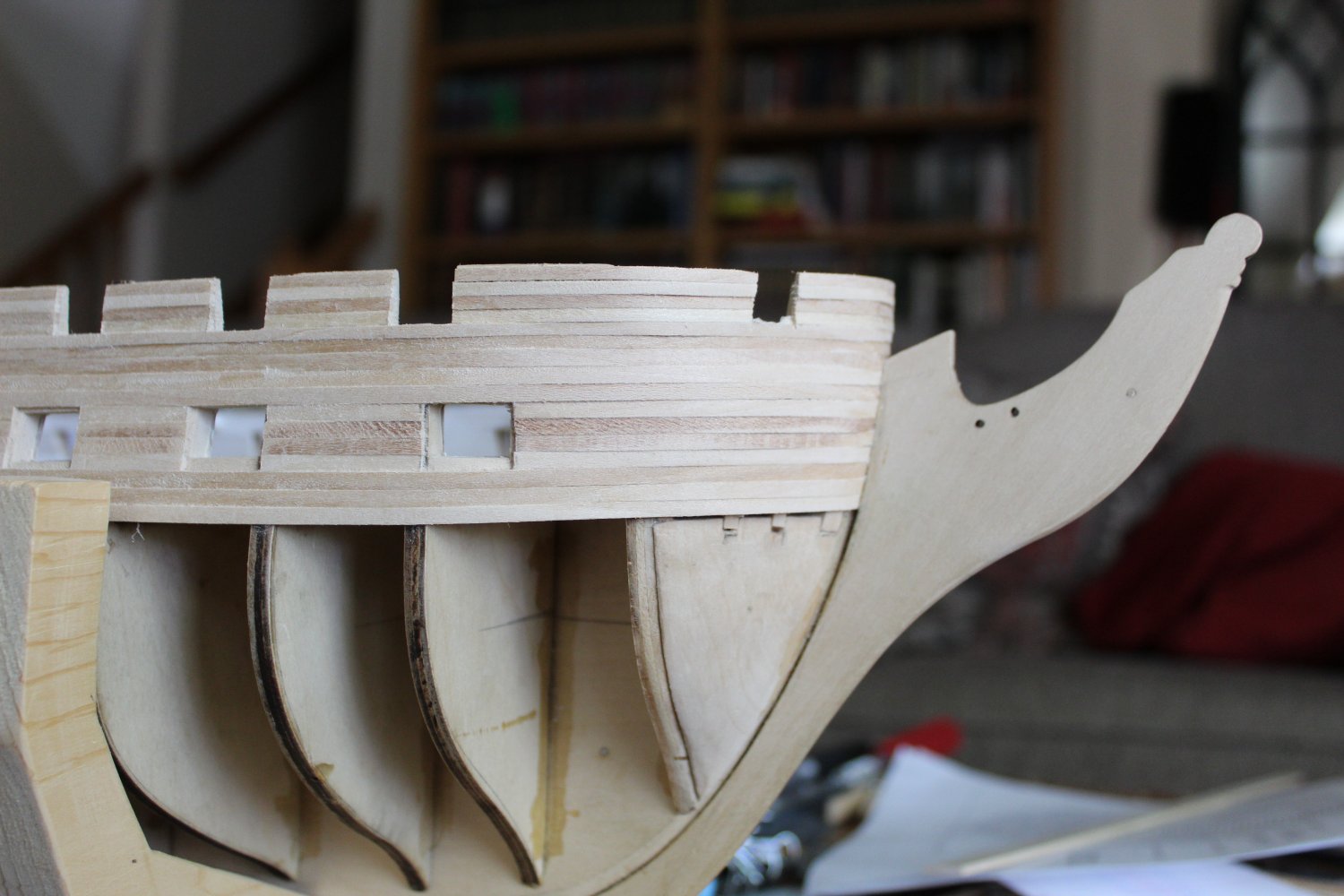
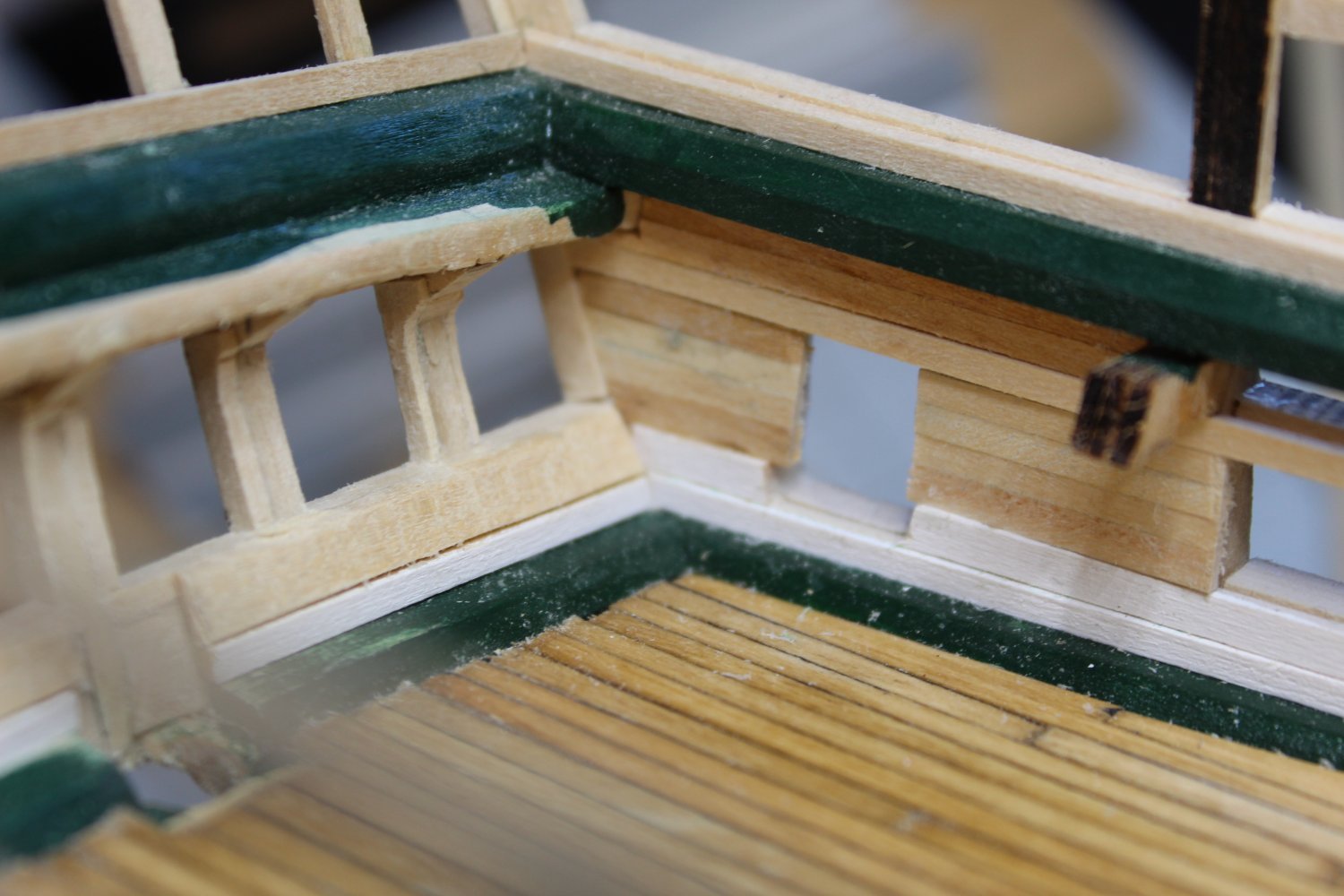
Finally, I could start doing what I was wanting to do at the beginning - plank the gun deck bulwarks! Here are a few photos:


-
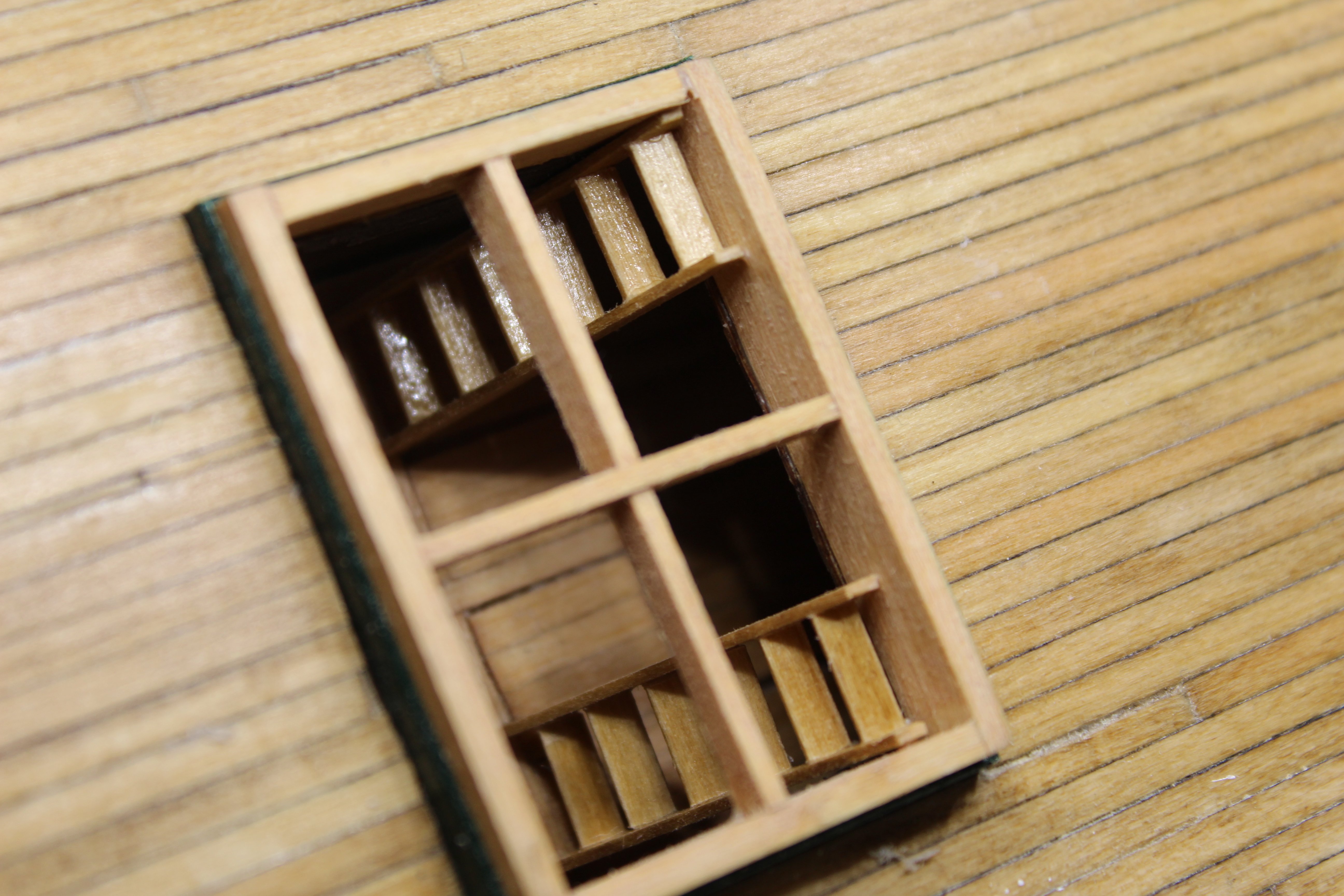
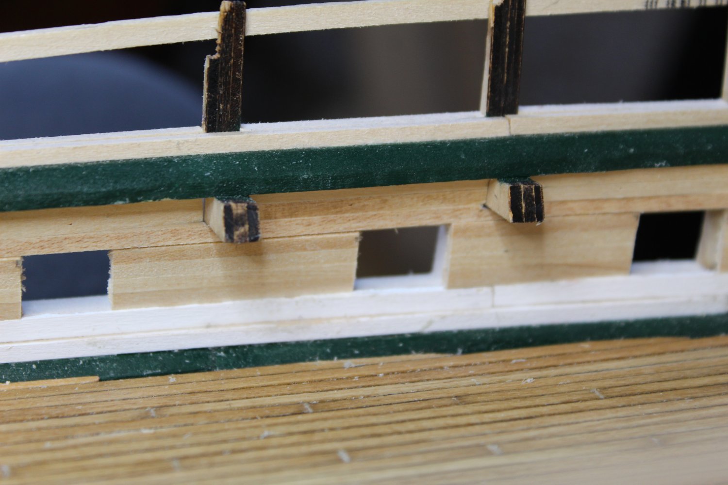
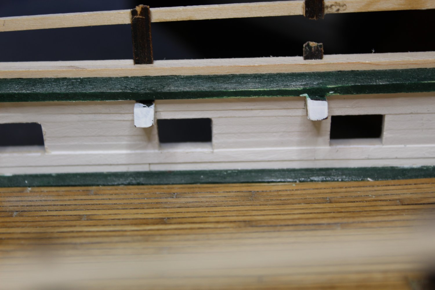
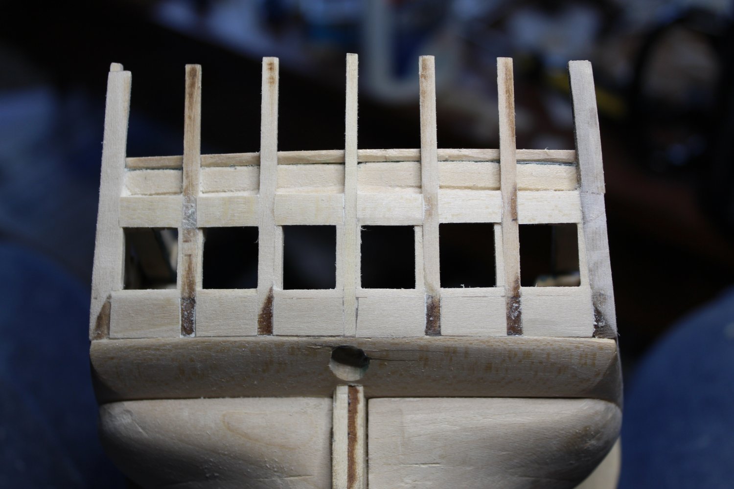
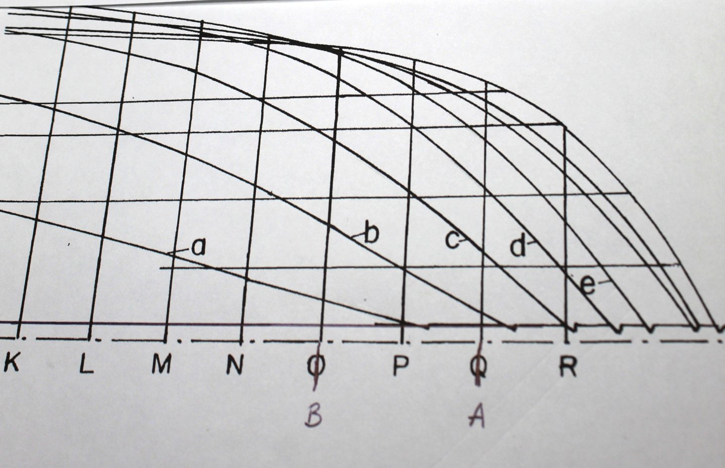
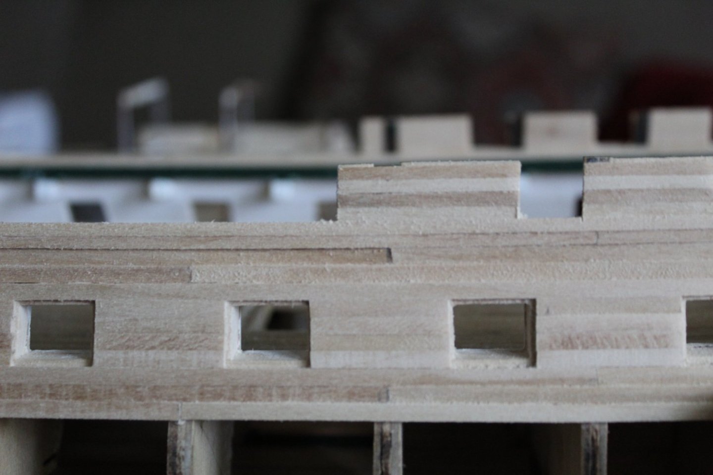
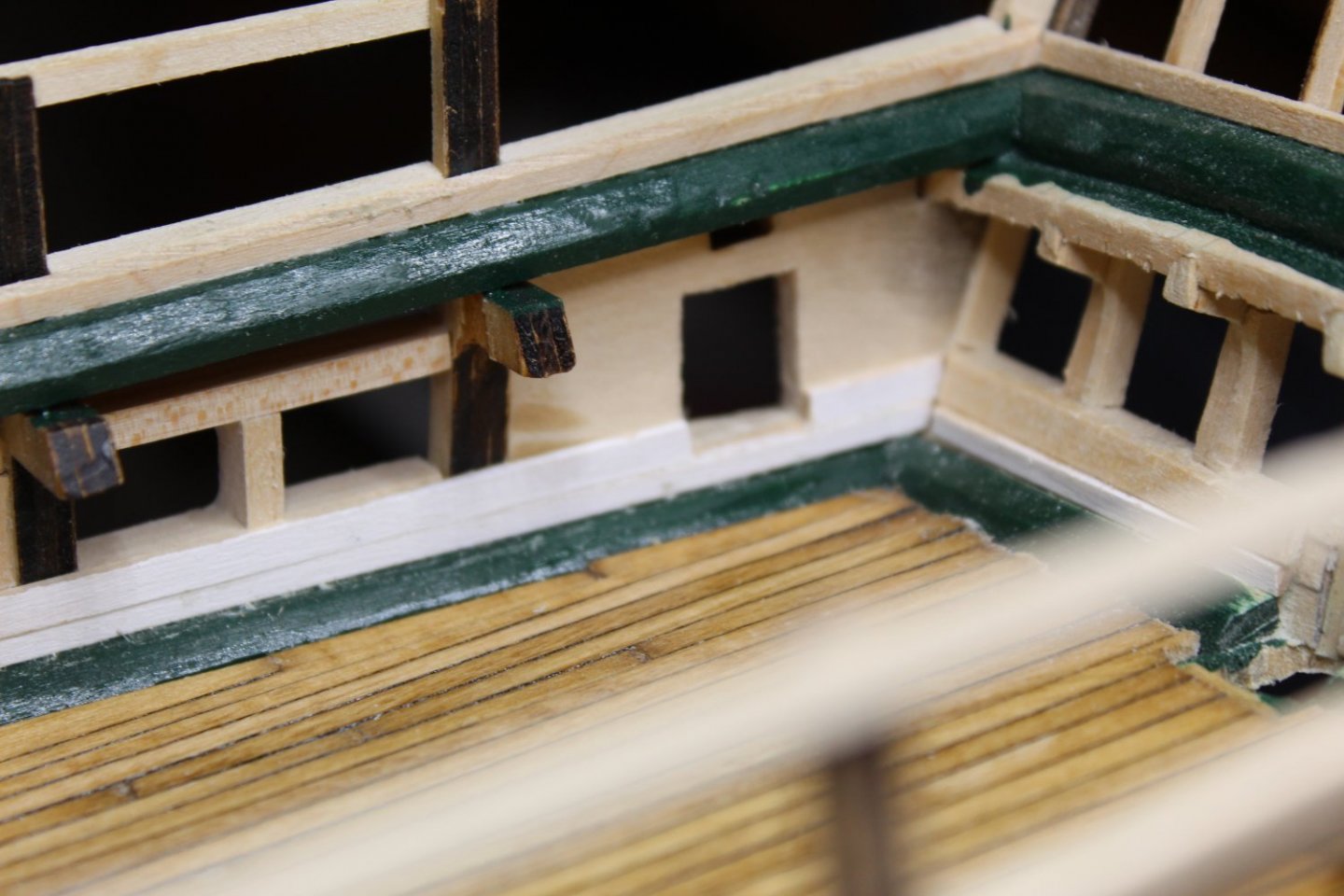
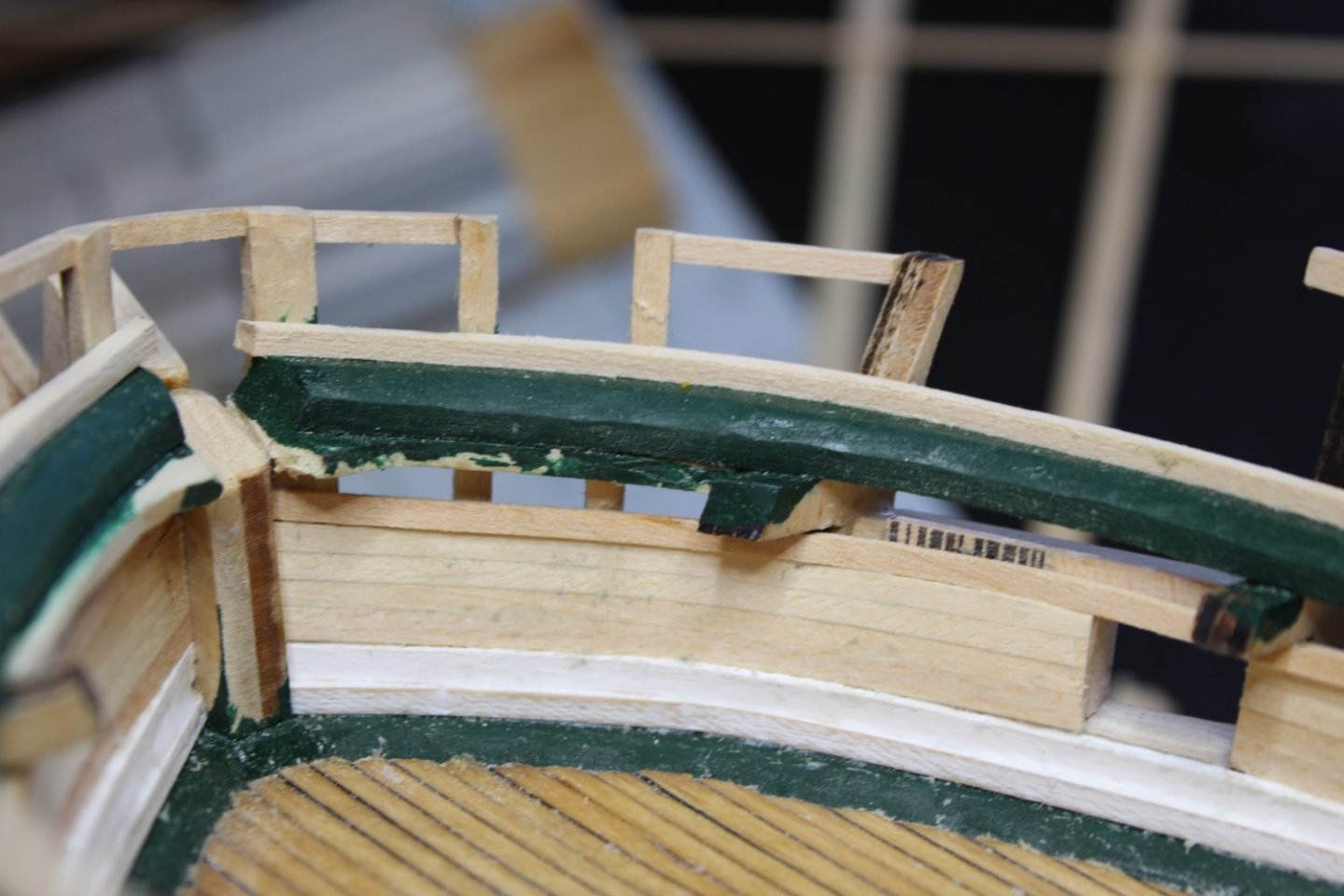
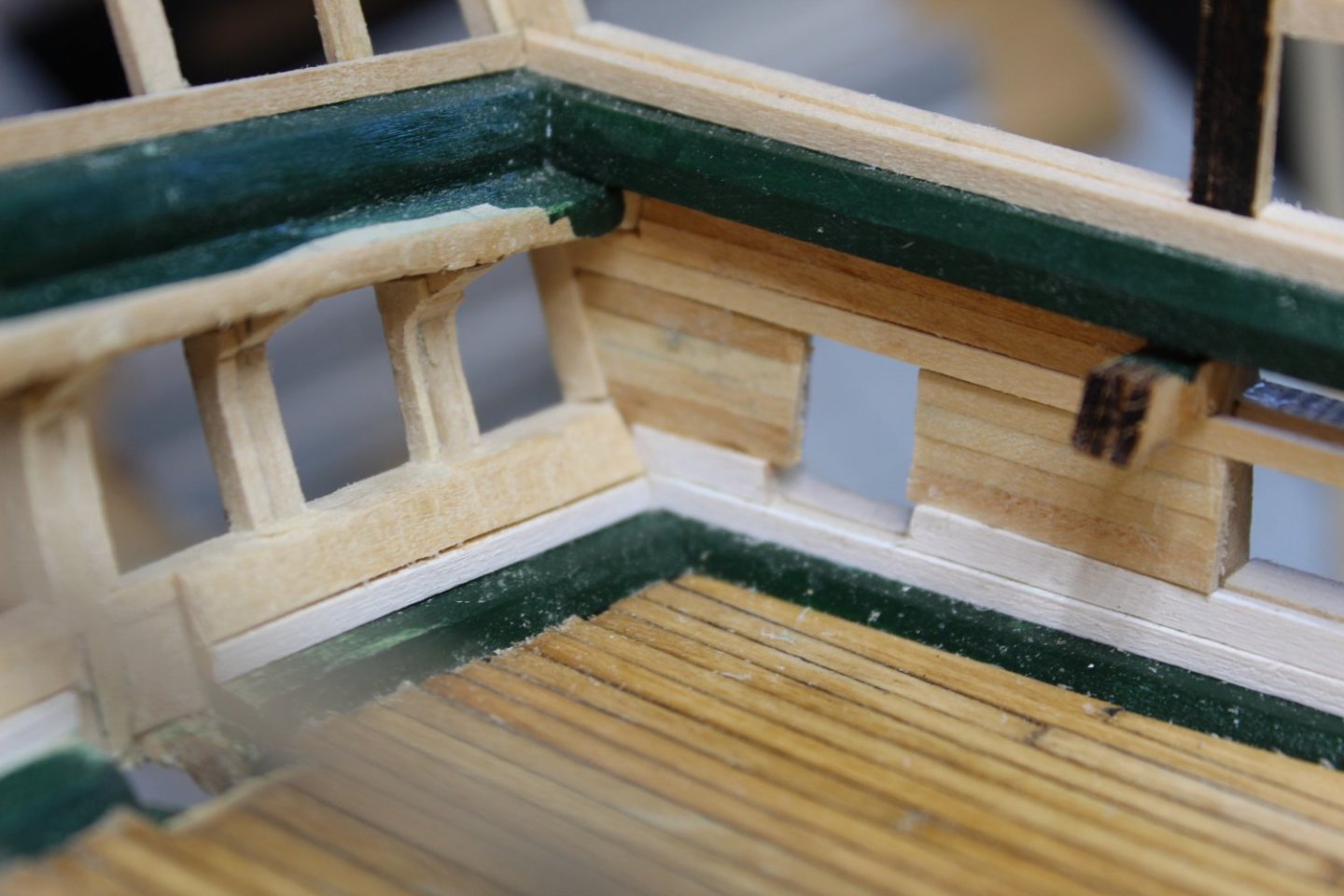
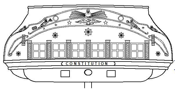
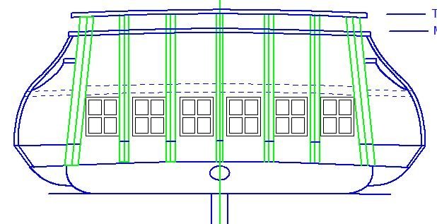
Next came framing the stern windows. Here's the drawing I am basing my stern from: And here is the drawing on how I was framing it: After careful measuring, I noticed that my vertical frames were not exactly where they needed to be, but I could correct by using offset fillers. Here's how it came out. Notice the filler pieces offset on either one side or another from the frames. Also, I put solid fillers below and above the windows to support the planking.

-
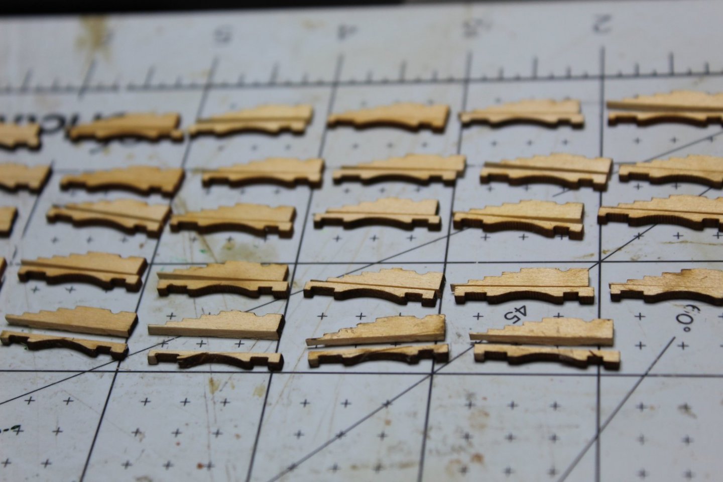
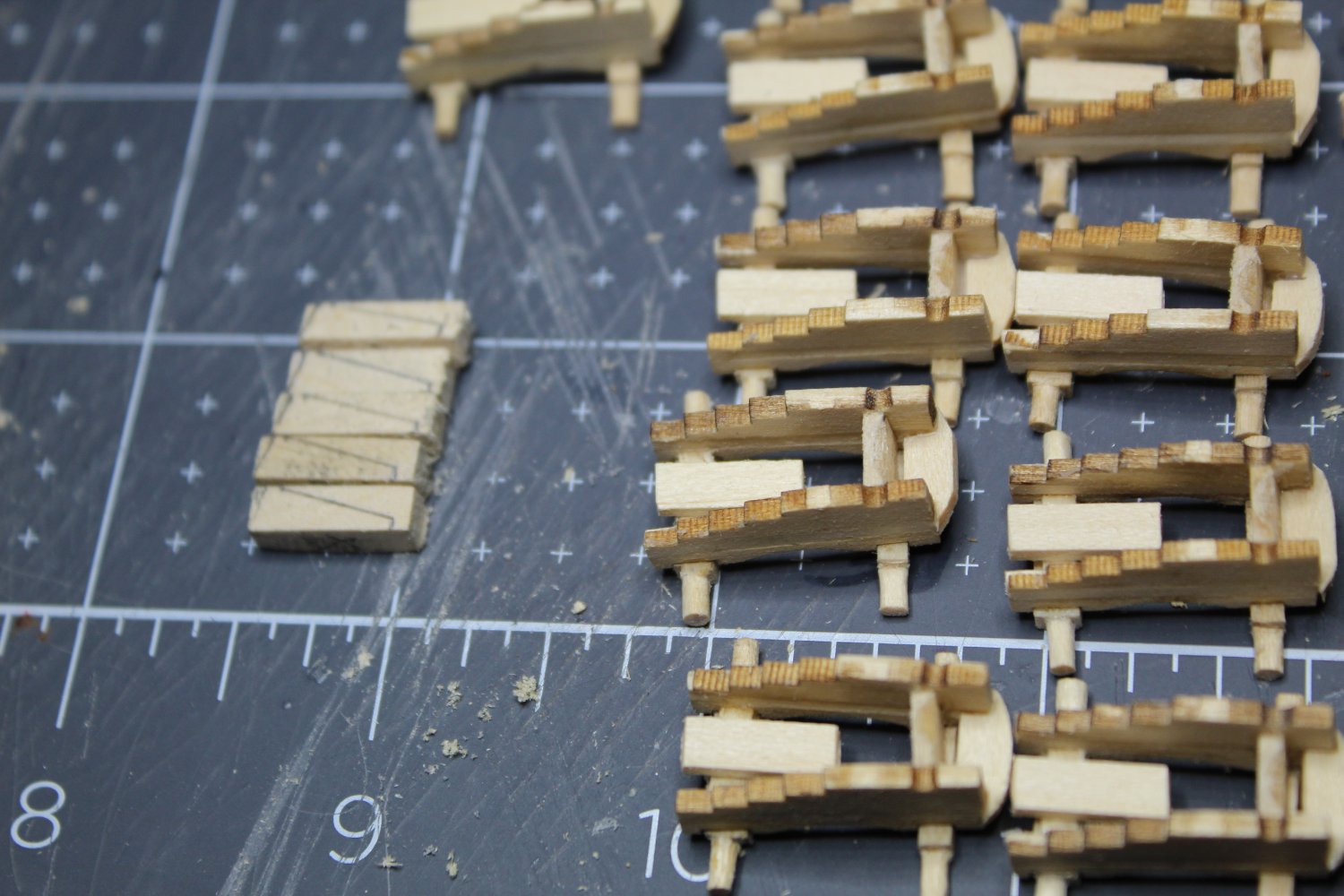
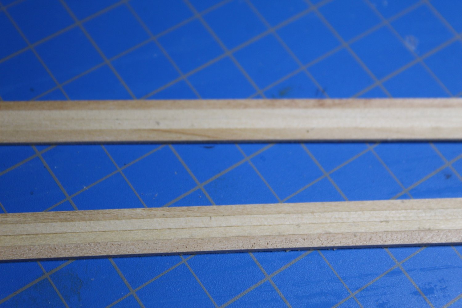
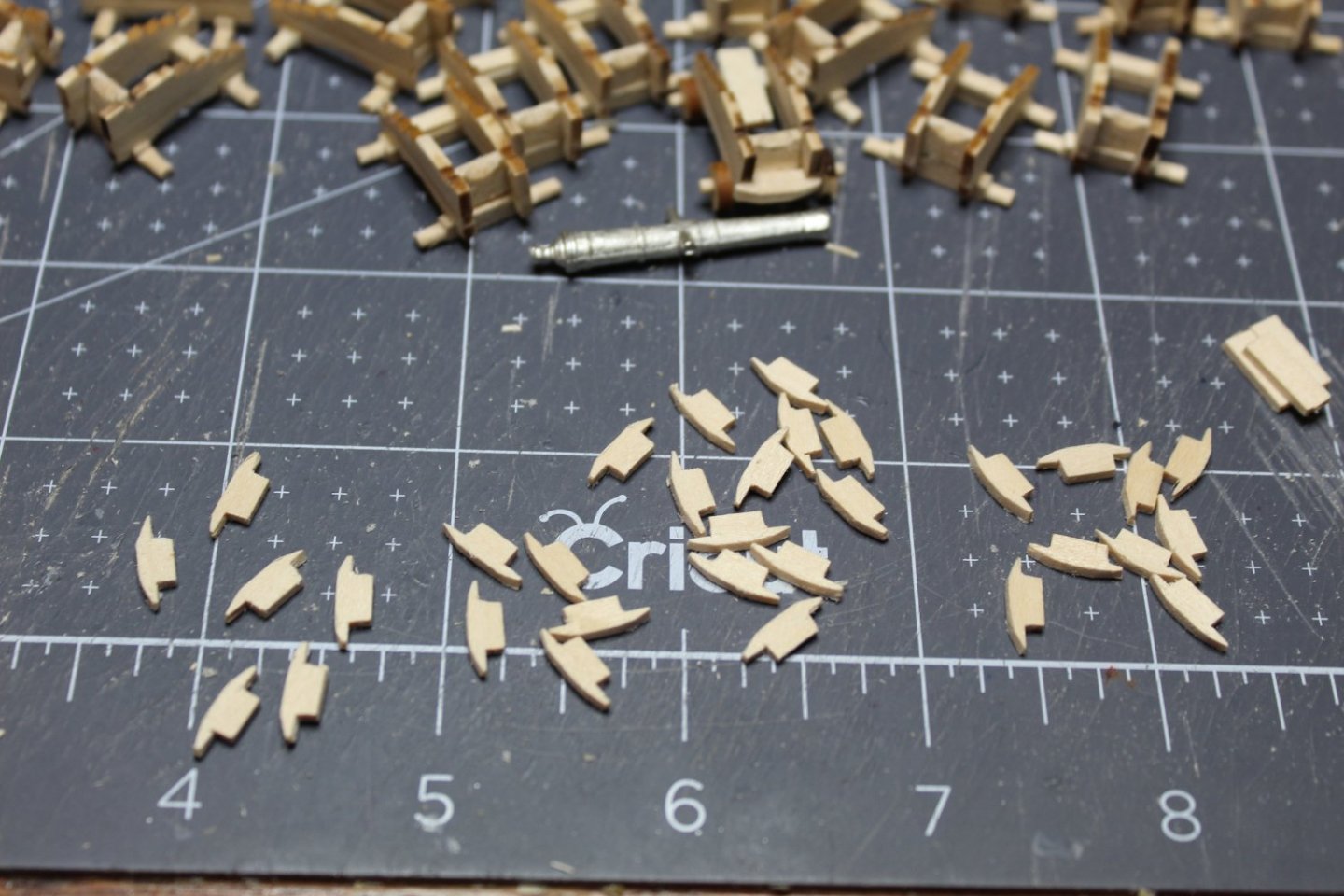
Happy with the fit, I went into gun carriage sides manufacturing (I needed another 58 for the gun deck). I sliced them all first using my "carriage slicer" above. Since I was cutting with the grain, pushing down with the razor blade was sufficient to part them. I then inserted a 1/16" piece in between, and once dry, packaged them all up for the time I will be making the carriages.