bthoe
-
Posts
72 -
Joined
-
Last visited
2 Followers

About bthoe

- Birthday 10/19/1961
-
 Marcus.K. reacted to a post in a topic:
USS Constitution by The Bitter End - Model Shipways - 1:76
Marcus.K. reacted to a post in a topic:
USS Constitution by The Bitter End - Model Shipways - 1:76
-
 Hi @Marcus.K., regarding the flag, here's a possibility from The many faces of the American flag. Note the white stripes on top and bottom:
- 165 replies
-
- 1
-
-
- Model Shipways
- constitution
- (and 5 more)
-
 Henke reacted to a post in a topic:
HMS Agamemnon by Henke - Caldercraft - 1:64
Henke reacted to a post in a topic:
HMS Agamemnon by Henke - Caldercraft - 1:64
-
Hi Henrik, I'm not very knowledgeable myself. However, one resource I have - Constitution All Sails Up and Flying by Olof Ericksen - refers to the pendant tackles and burton pendants as the same thing. They are first over the mast head before the shrouds and had thimbles on their ends to which tackles were attached to haul up the shrouds (so were there to assist in lifting). On Constitution, there were sets (port/stbd) on the lower masts and topmasts. Hope that helps!
-
Kenneth Powell reacted to a post in a topic:
USS Constitution by bthoe – Model Shipways – Scale 1:76.8 – 1812 era
-
ERS Rich reacted to a post in a topic:
USS Constitution by ERS Rich - Model Shipways - 5/32
-
PaddyO reacted to a post in a topic:
USS Constitution by bthoe – Model Shipways – Scale 1:76.8 – 1812 era
-
Unegawahya reacted to a post in a topic:
USS Constitution by bthoe – Model Shipways – Scale 1:76.8 – 1812 era
-
Unegawahya reacted to a post in a topic:
USS Constitution by bthoe – Model Shipways – Scale 1:76.8 – 1812 era
-
Unegawahya reacted to a post in a topic:
USS Constitution by bthoe – Model Shipways – Scale 1:76.8 – 1812 era
-
Unegawahya reacted to a post in a topic:
USS Constitution by bthoe – Model Shipways – Scale 1:76.8 – 1812 era
-
Unegawahya reacted to a post in a topic:
USS Constitution by bthoe – Model Shipways – Scale 1:76.8 – 1812 era
-
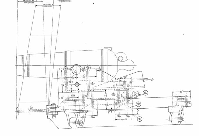
Can the upper part of the carriage be moved forward? See sketch from Navy plans:
-
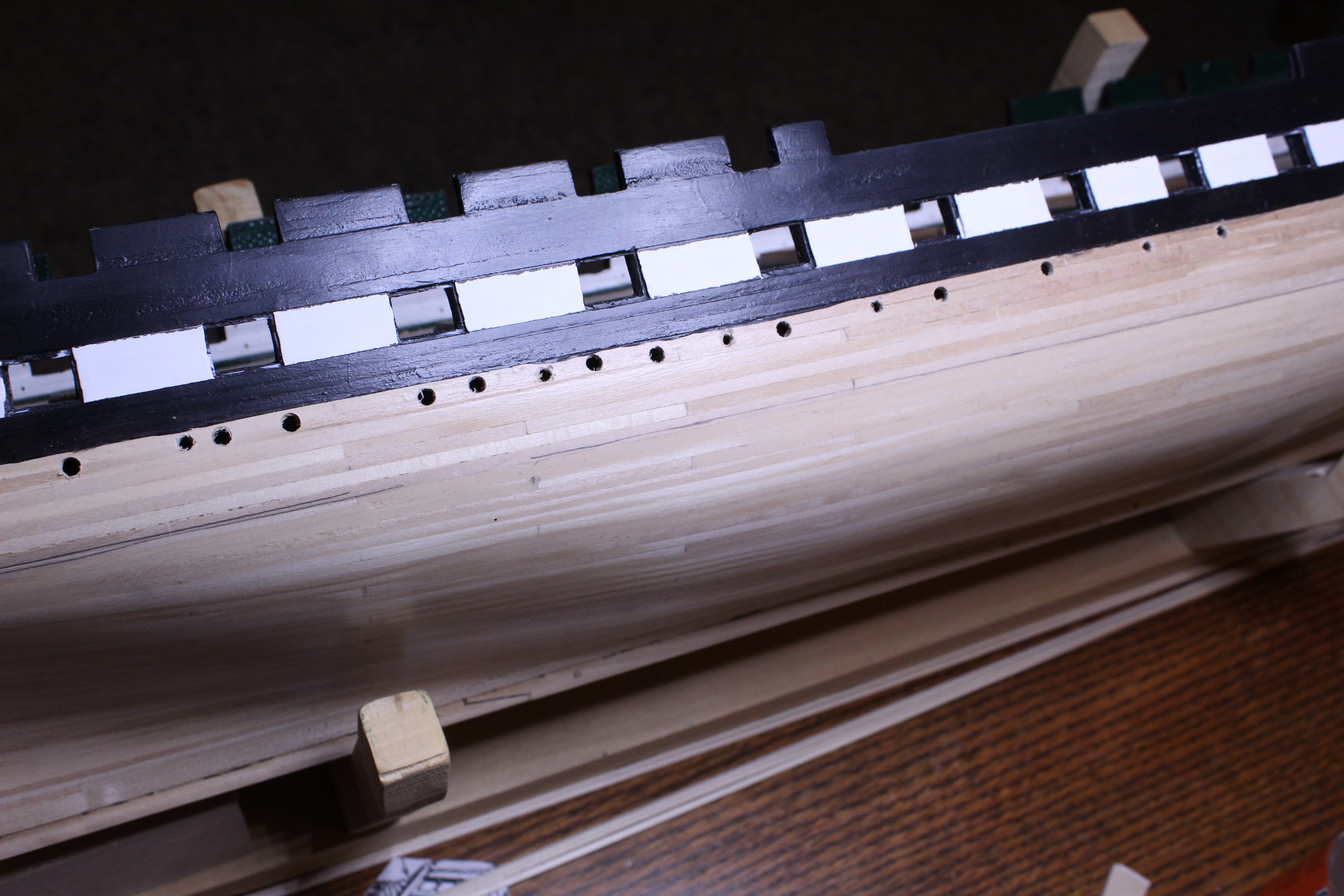
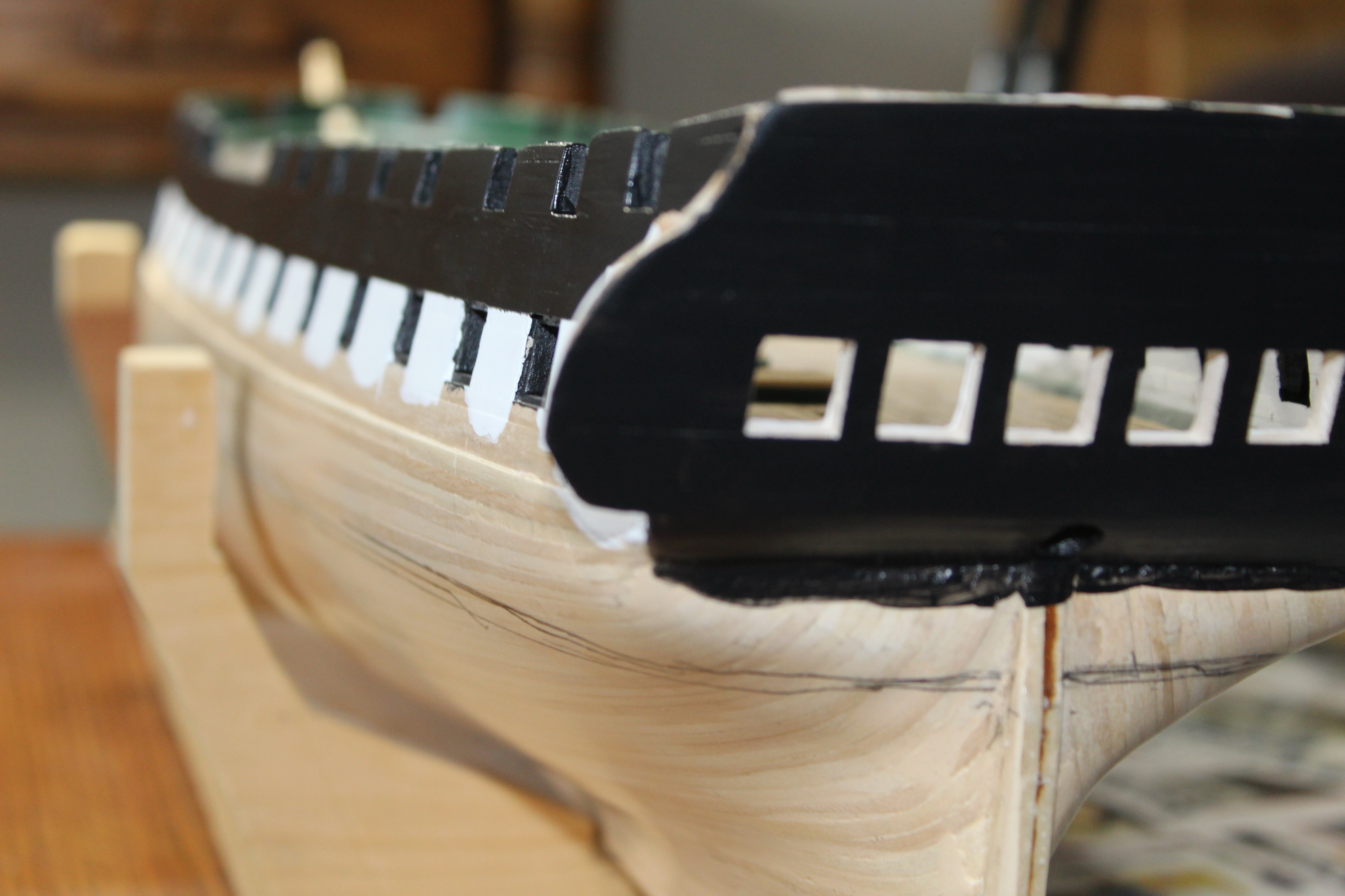
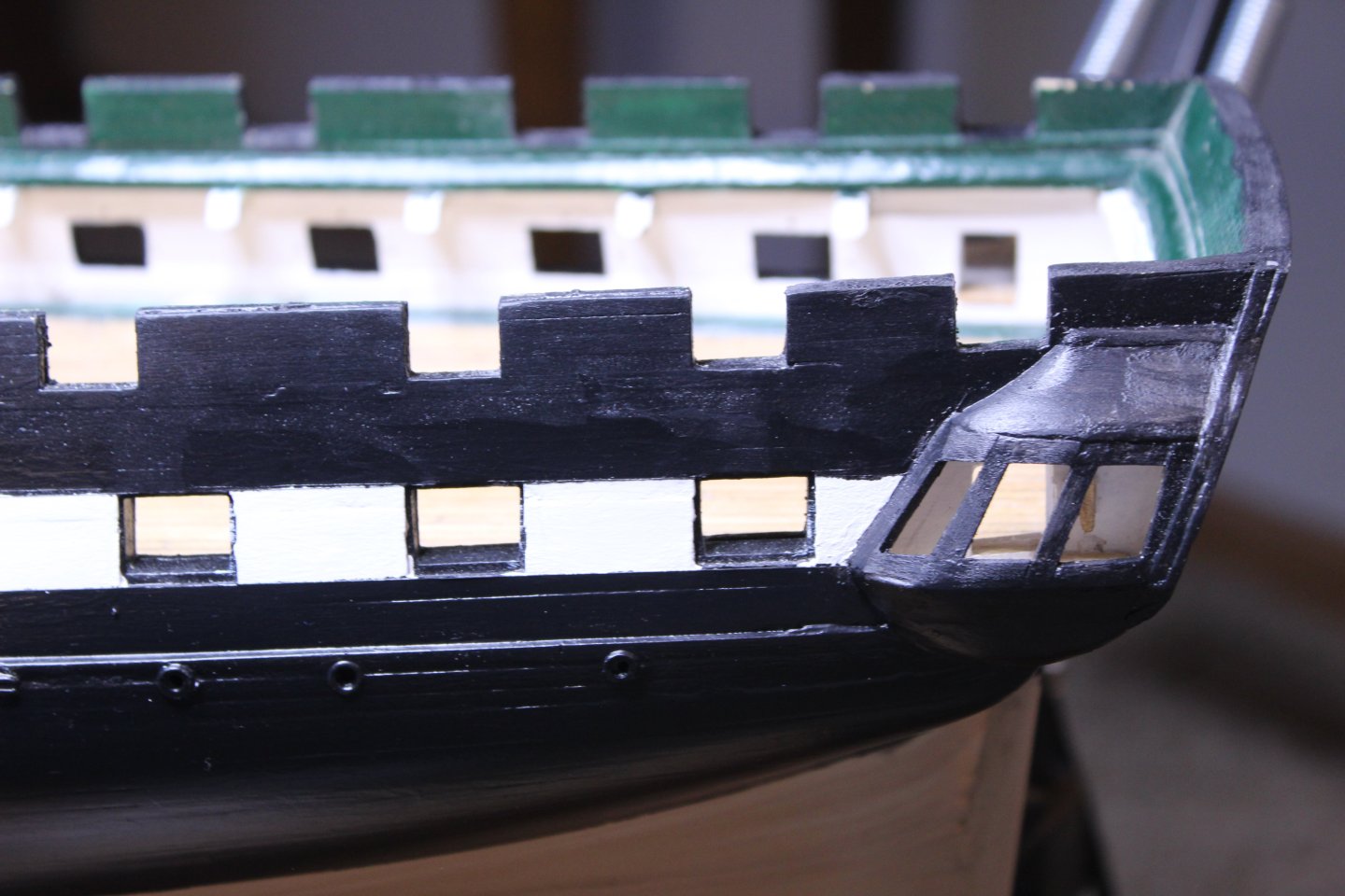
Hi Jon, Regarding port holes, yeah, I was aware of it. Actually, the whole thing looks to be proud of the hull surface, but only slightly - like a plate that is screwed to the outside. I just envisioned losing about 1/2 of them inside the hull if I did it the "correct" way and so I settled for what I did. If it ends up bothering me enough, I may file down the whole thing to about 1/2 thickness - we'll see. I like what you did with the scuppers - I just didn't have the patience for it. Mine, like the port holes are "too proud" of the surface. There will be other things down the road that will require more patience and will be worth the kit bashing time for me to work out - like your canopy frames (great job!). Thanks for the "likes" folks. This weekend, I'll be putting more time into it, and will hopefully be timelier in posting to this build log🙄.
-
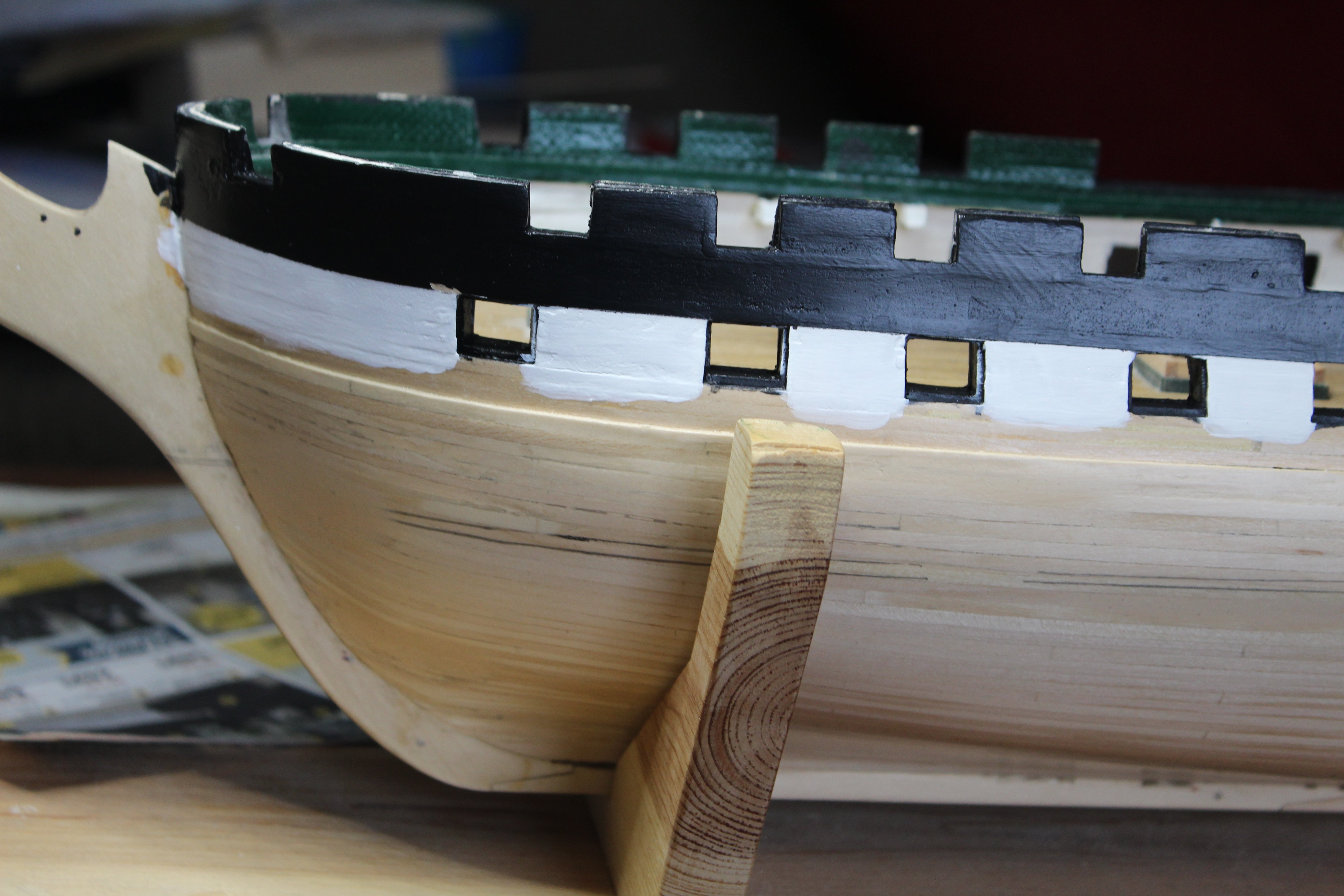
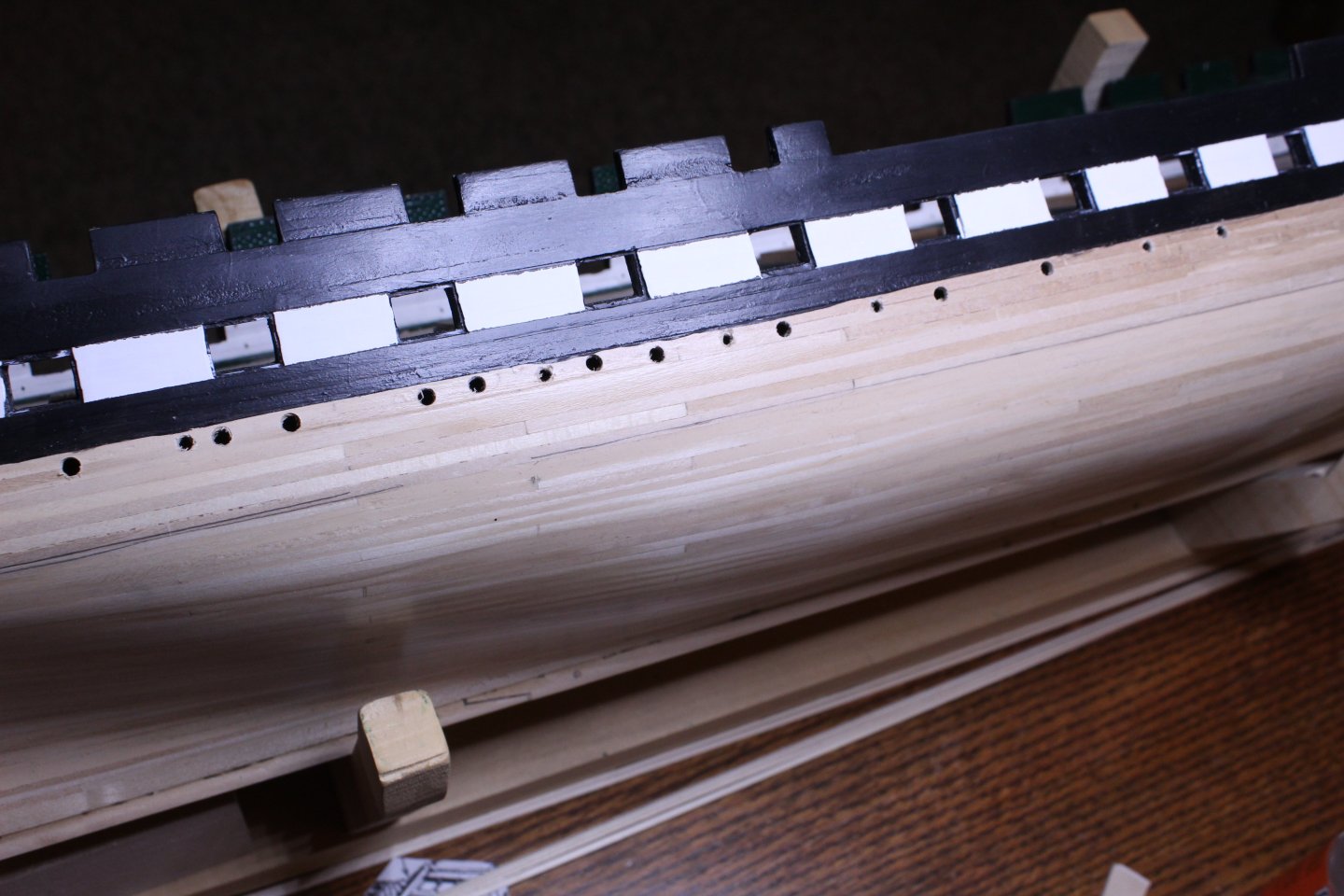
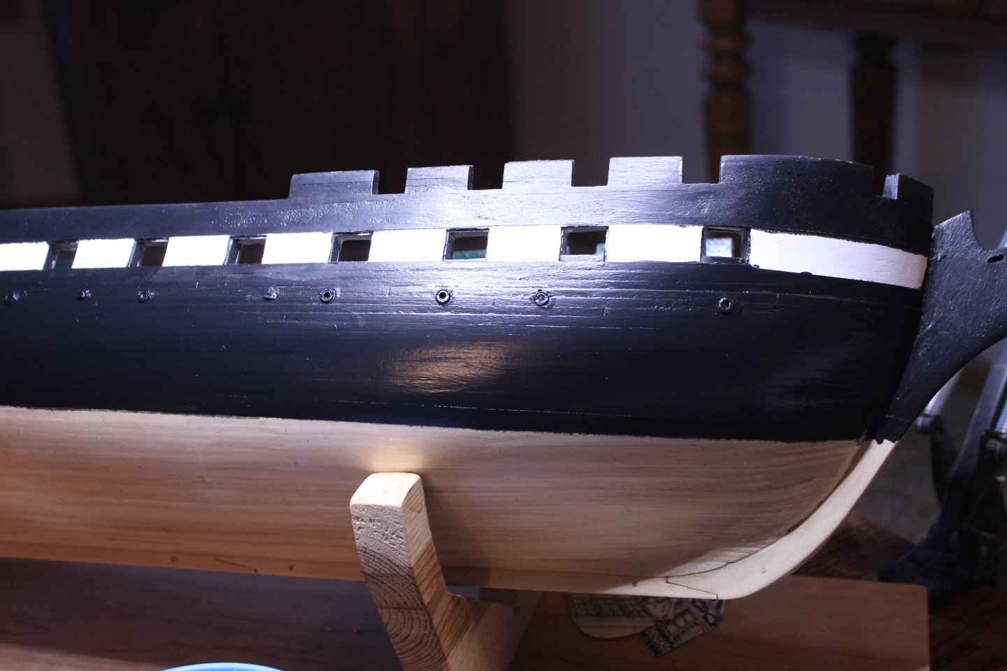
Finally, I drilled holes for port lights and scuppers. Here they are installed and the paint extended to below the waterline: I used the MS scuppers rather than create my own, so they are closed, which is ok by me. It just means that they aren't forced open by escaping water. This gets me up to date. Now I can figure out if I should: 1. Copper the bottom 2. Detail the outsides of Qtr Galleries and Stern 3. Add the head rails 4. Something Else? For those of you who are beyond these, which did you choose, or which do you wish you would have done first? Thanks,
-
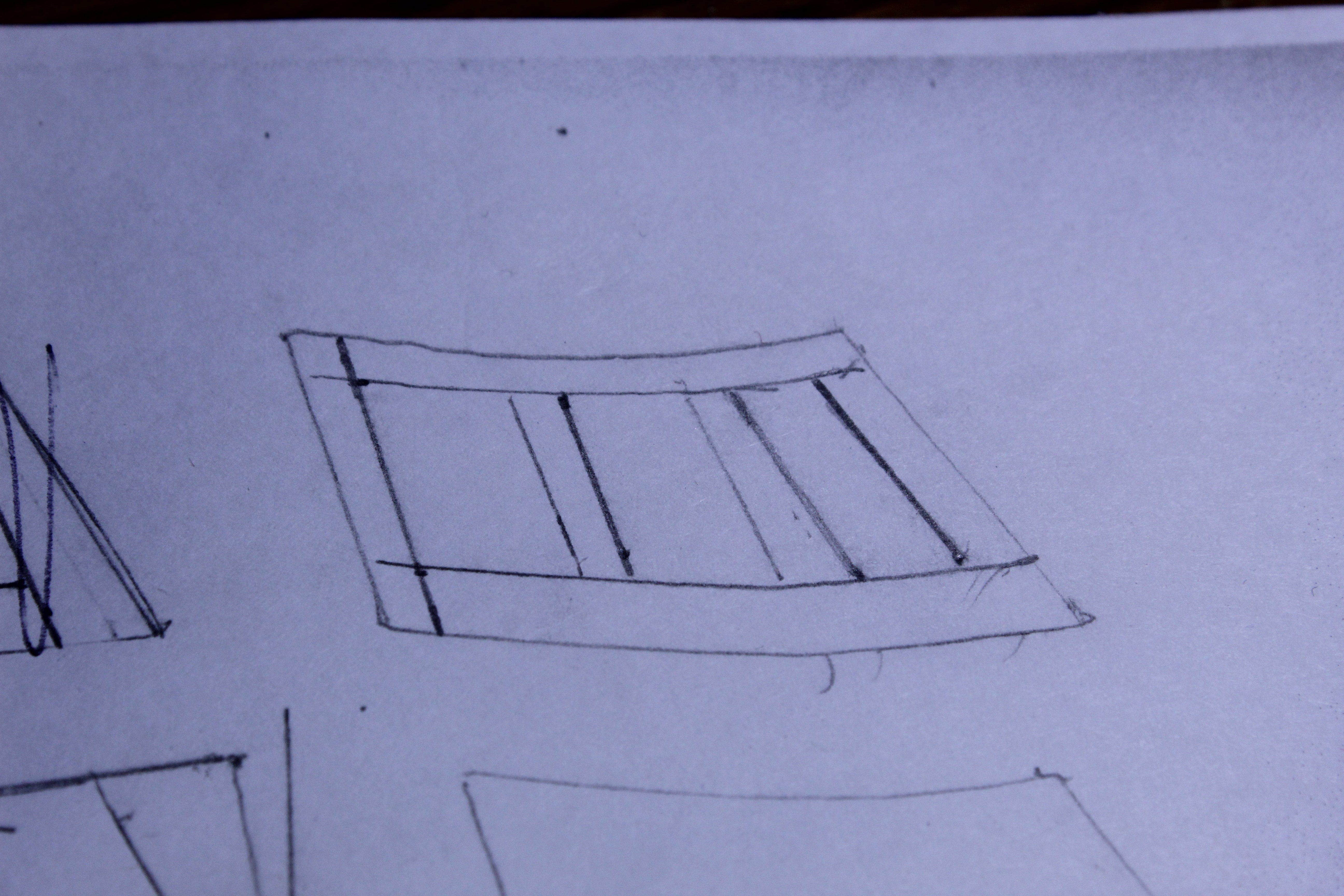
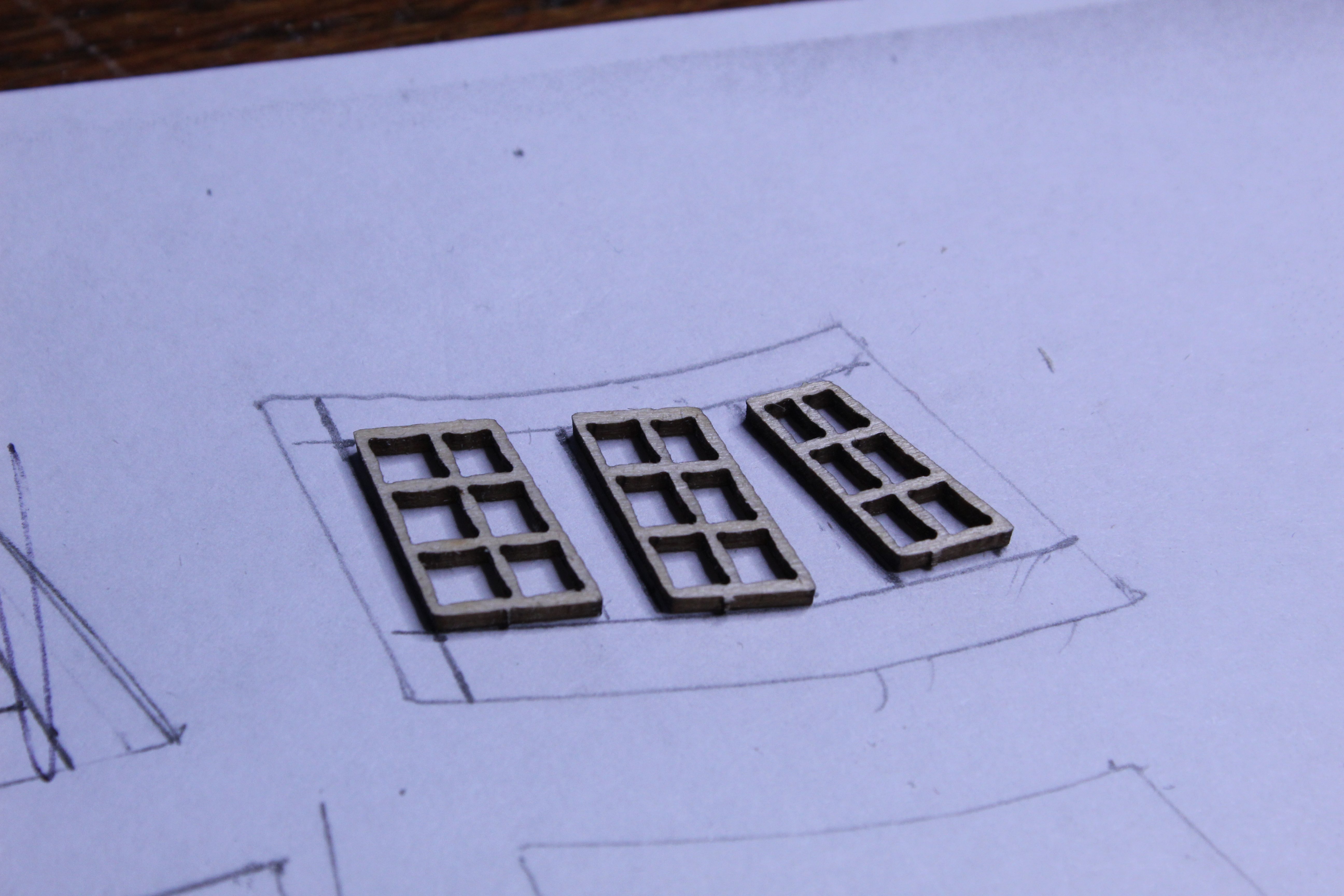
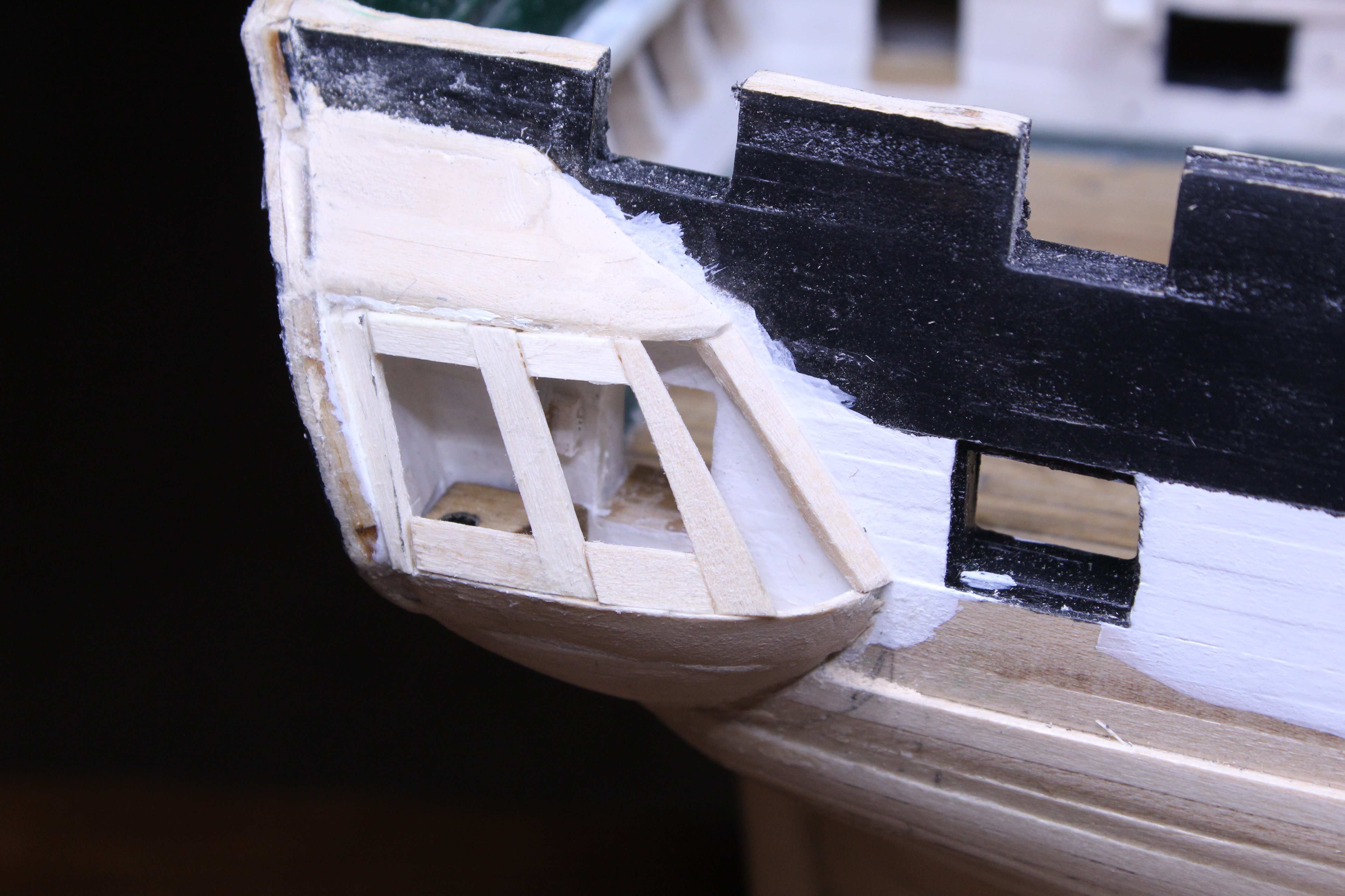
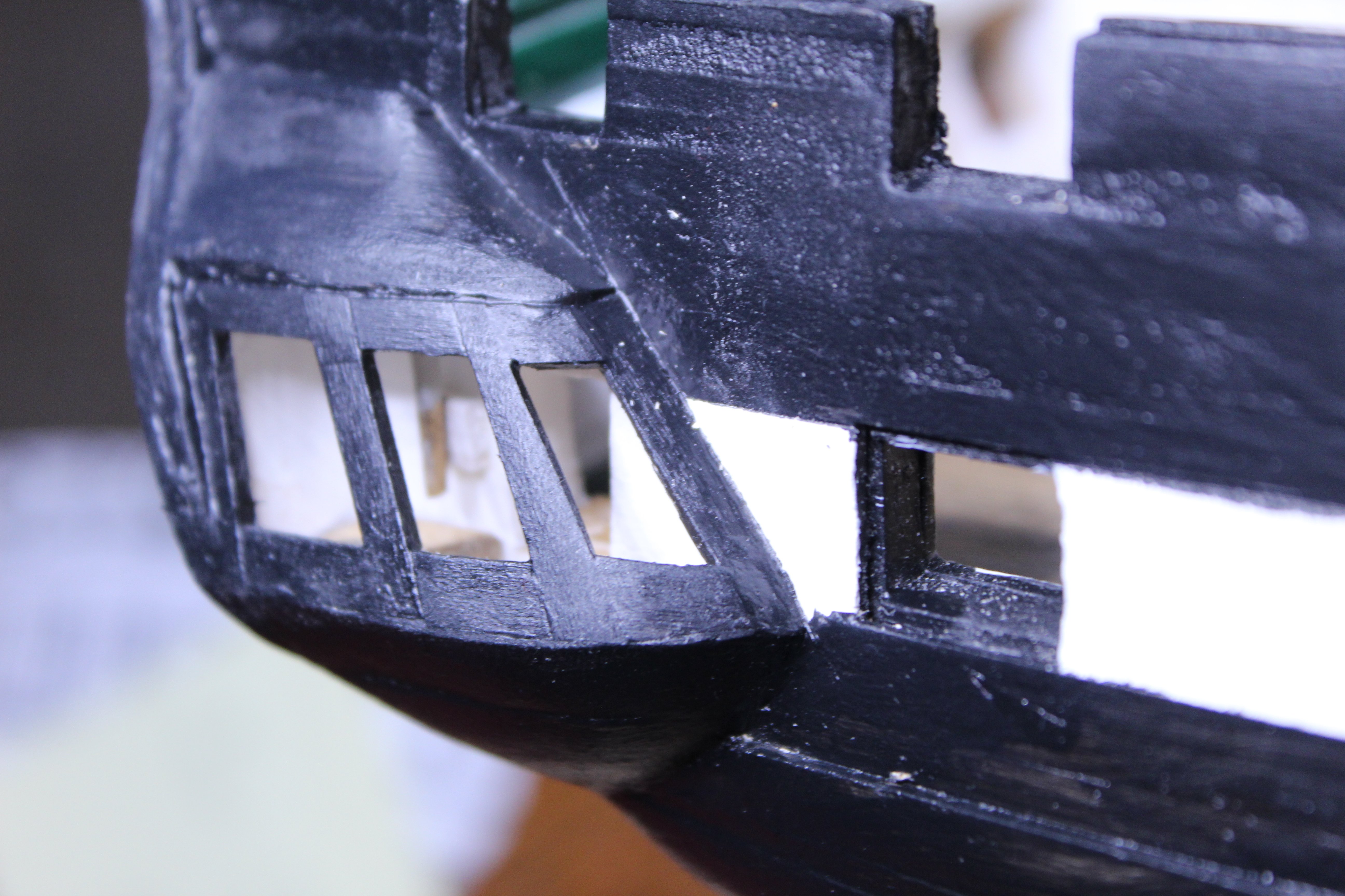
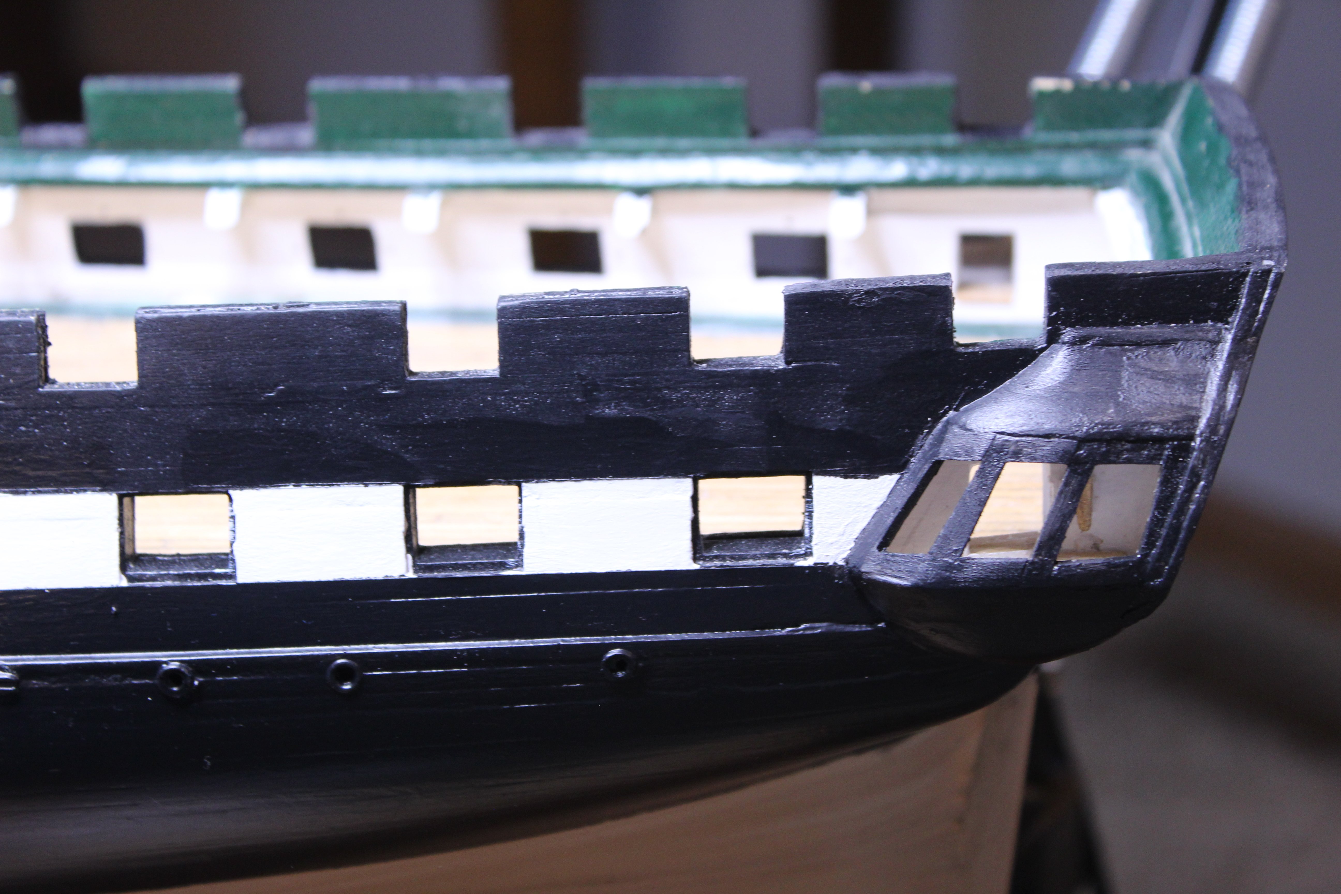
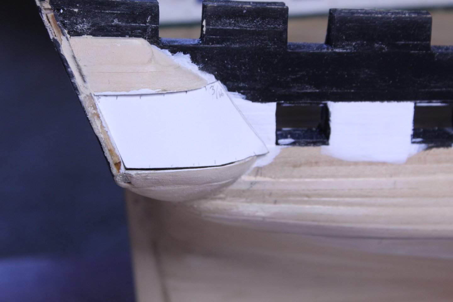
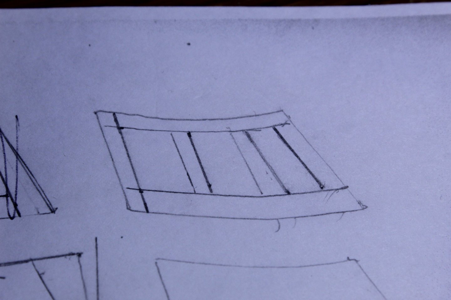
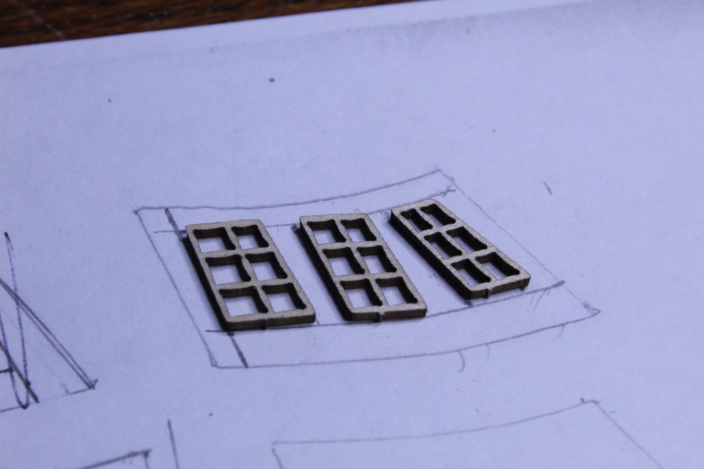
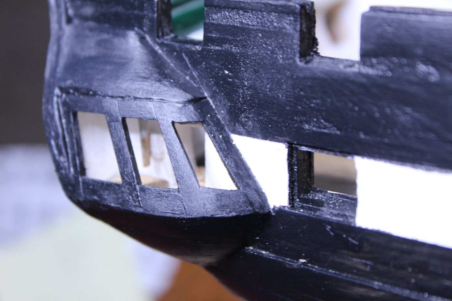
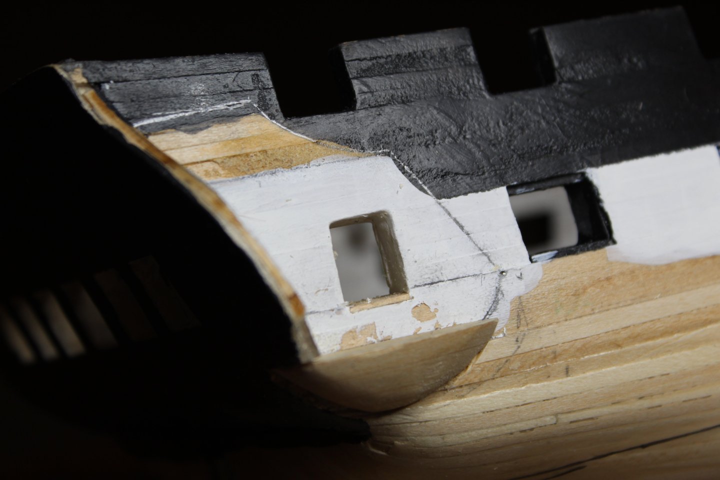
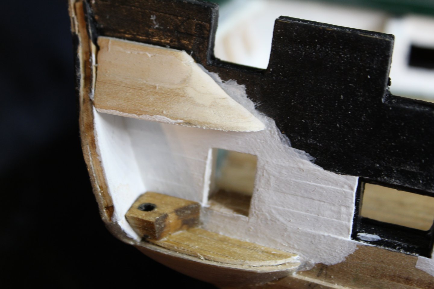
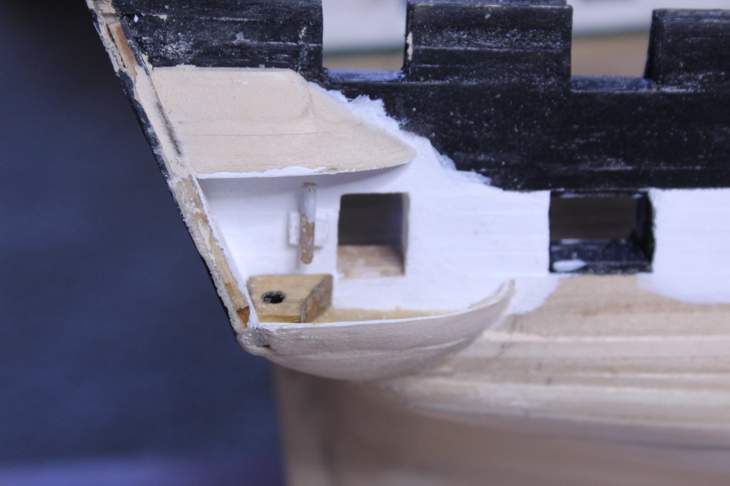
Next came framing for the windows. I decided to see whether or not I could make the MS laser cut windows work here, and so first created a template for the opening. For now, I'll leave the windows out. I have decided at least for now that I won't be glazing the windows on either the quarter galleries or stern so that there is a better view through them, but until I put the windows in place that decision can change any number of times . Then laid it out on paper with measurements of the windows. Next, I overlaid the windows to see what it looked like. And went ahead with framing. All along the way, I double-checked to make sure the windows fit. I didn't get a pic of the finished last window framed until it was painted. Near disaster hit when I was doing the port side - the forward-most window broke off at the bottom. But I managed to find all of the pieces, and glue them all together. It's still pretty fragile, but will do to get it into place.

-
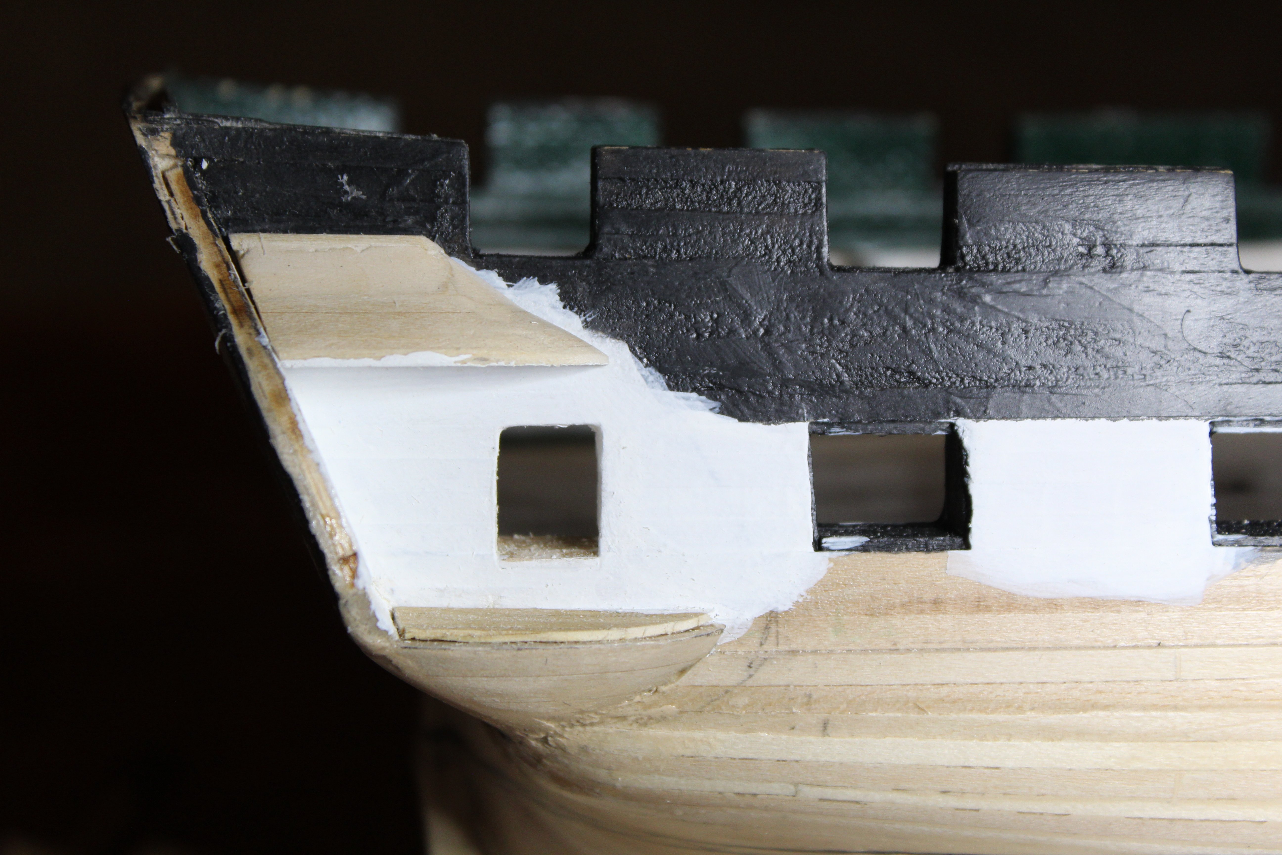
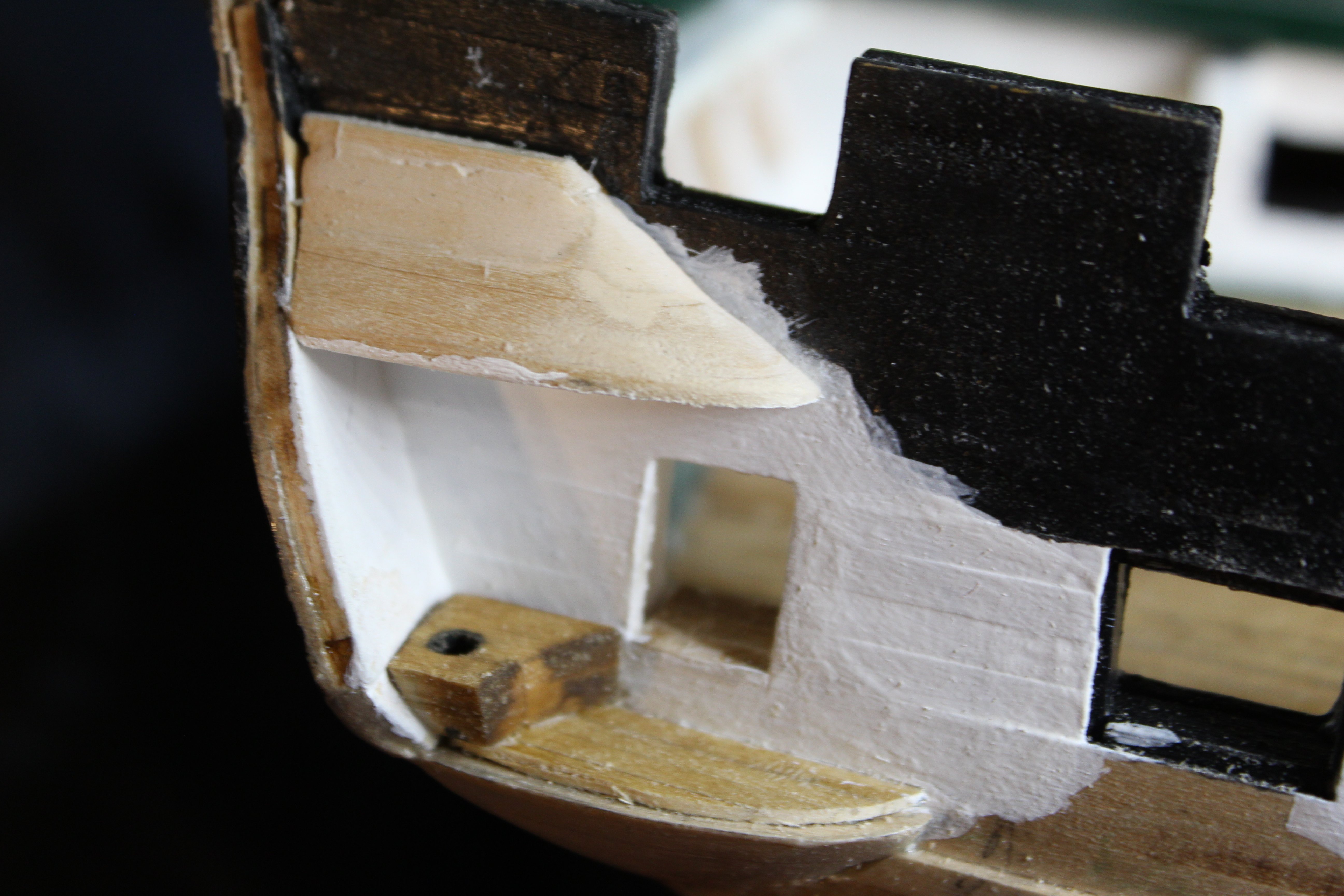
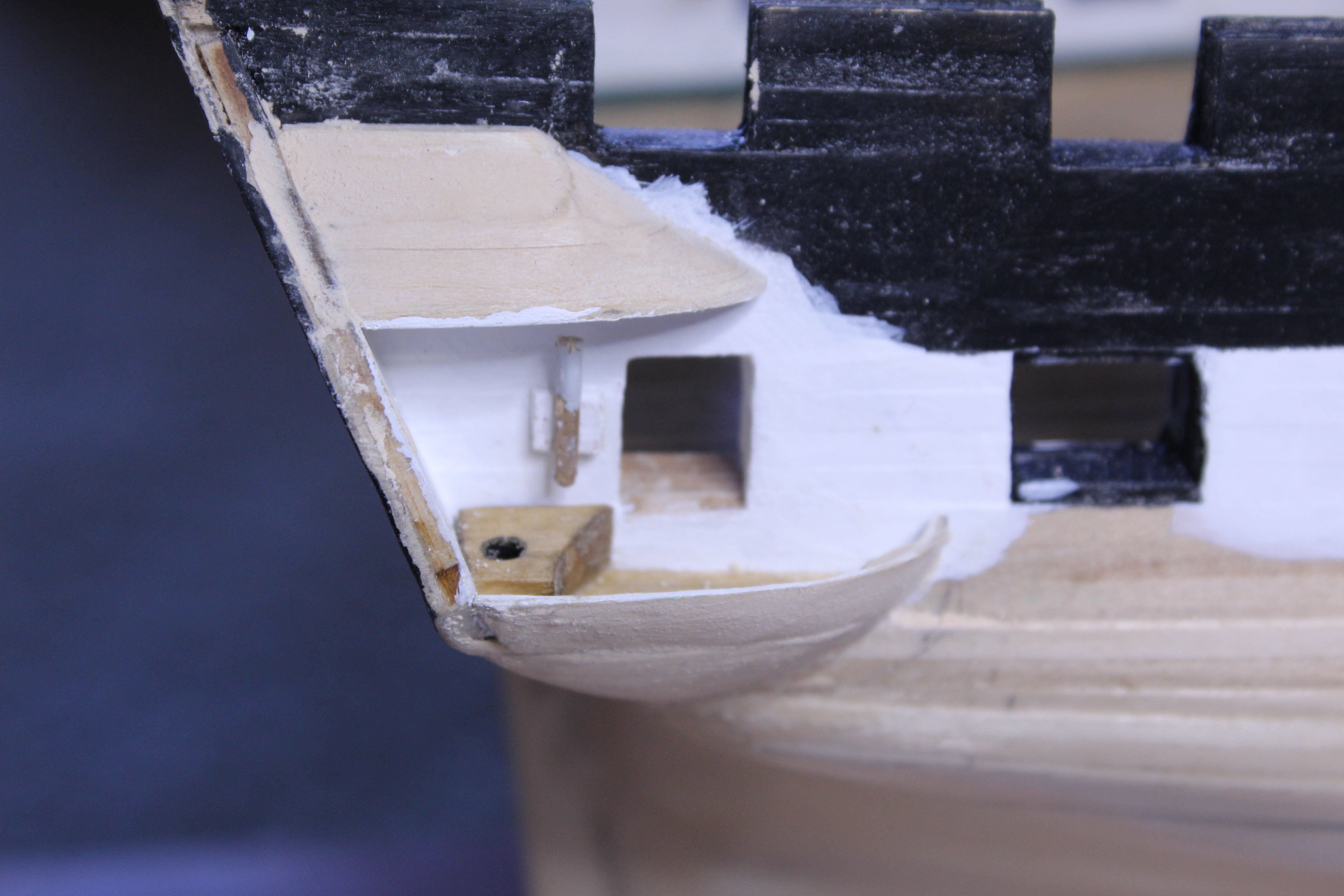
I decided to detail the interior of the quarter galleries somewhat, knowing visiblity will be somewhat limited. Initial measurements indicated that the floor would rest on the top of the fairing block. I made the fairing block from a laminate of three 1/8" sheets of basswood, and the bottom block from a laminate of two 1/8" sheets of basswod. The laminates were to simulate planks - not sure it made much difference, but it's there. I then used my rotary tool with a sanding drum to shape the blocks, and in the case of the "bottom block", I hollowed it out to make a wall (see photo below). First, the fairing block installed Next, the floor attached. Also, the roof block attached. Next, the Captain's (or is it Commodore's?) head. And finally a lamp. Although out of scale, it gave it a little more to look at. Also the "bottom block" has been attached forming the outside wall.

-
Next step, getting ready for the dreaded quarter galleries.


-
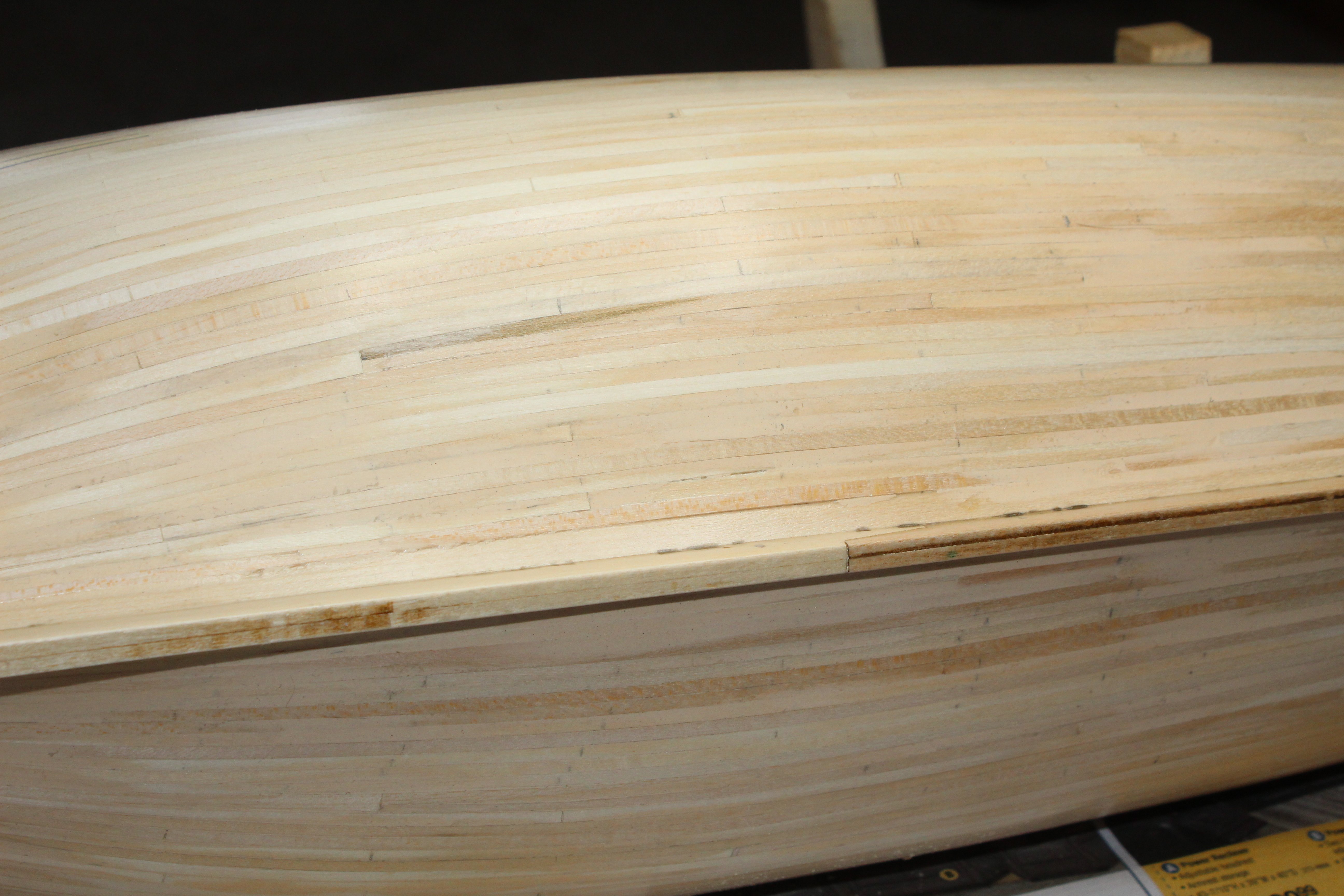
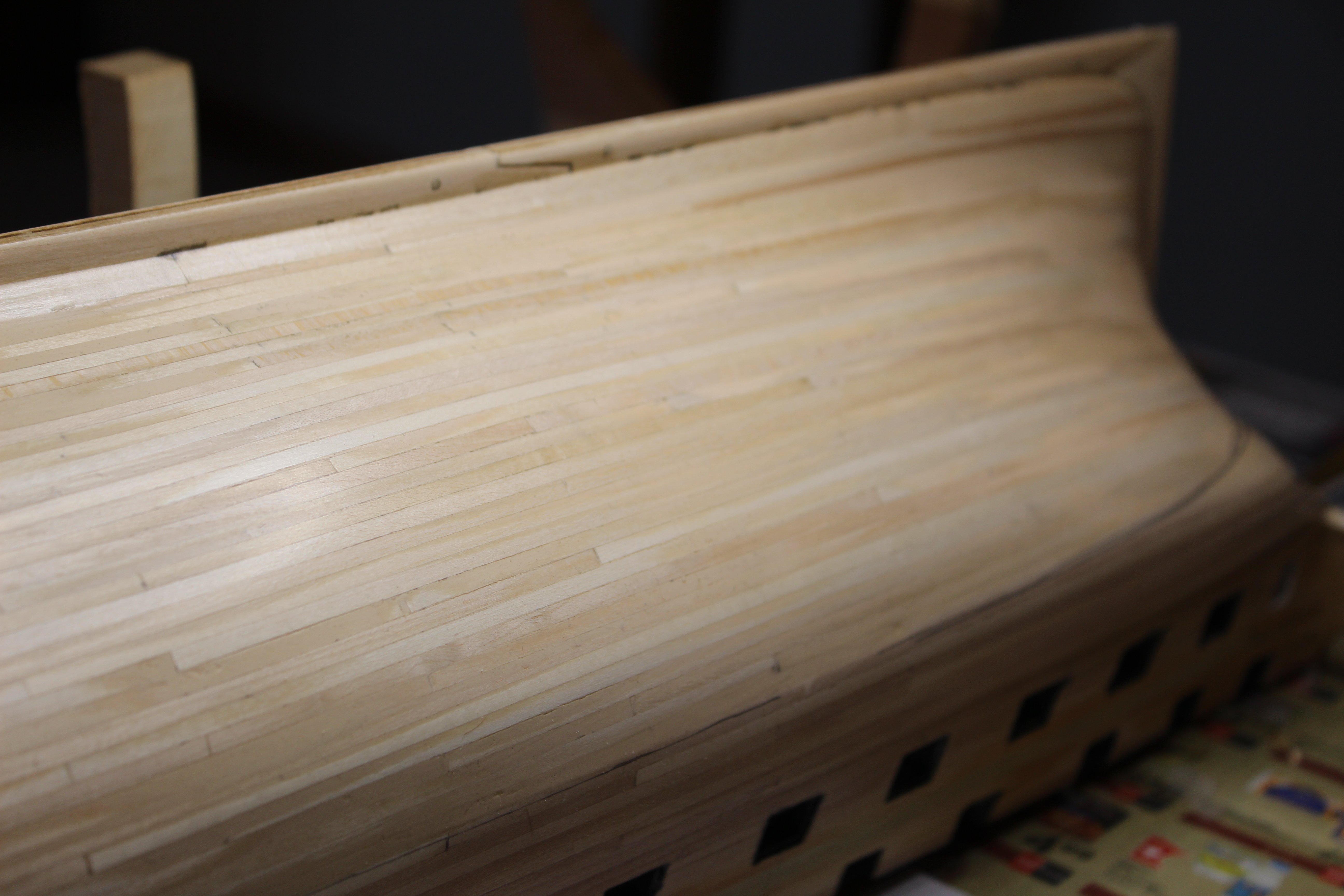
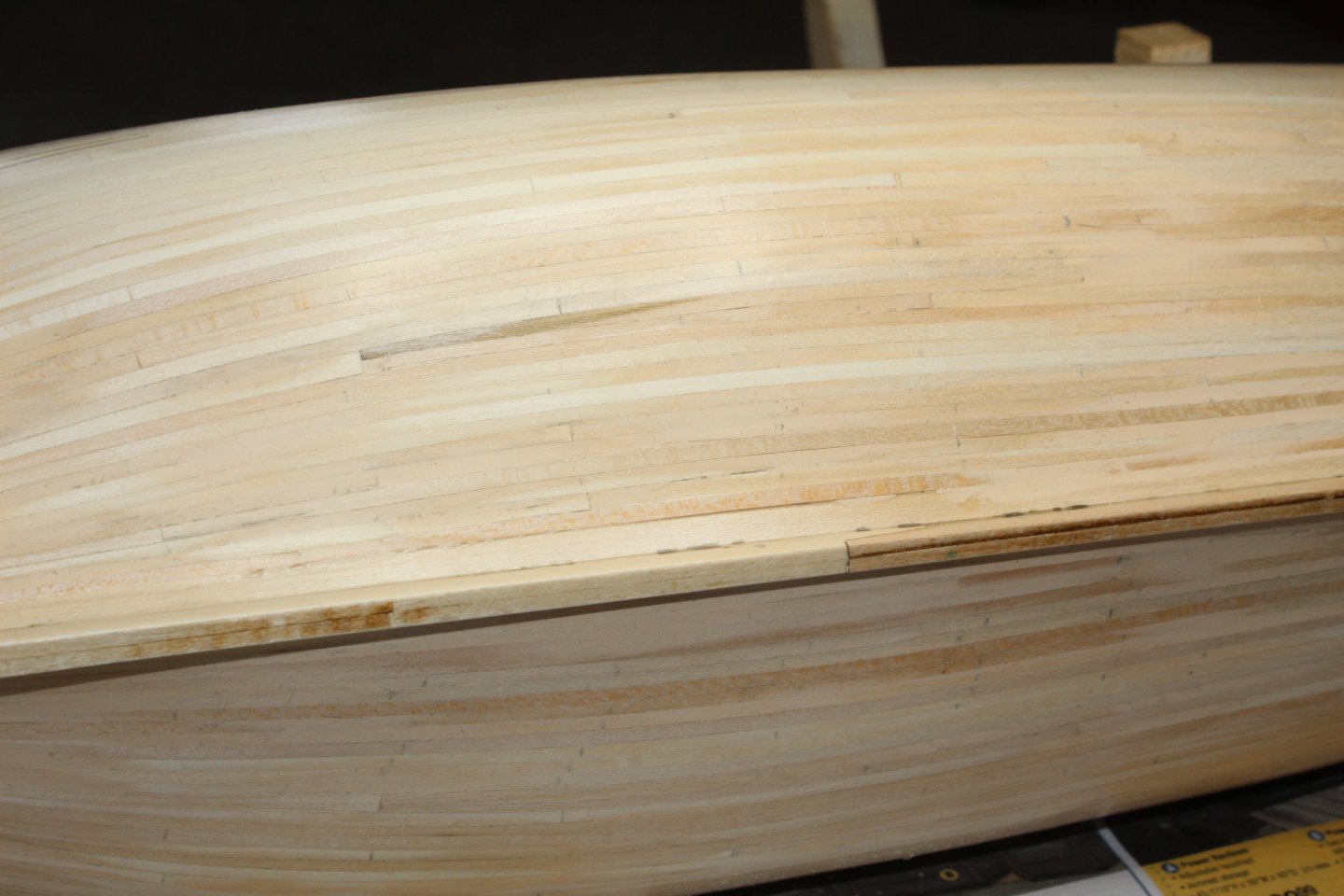
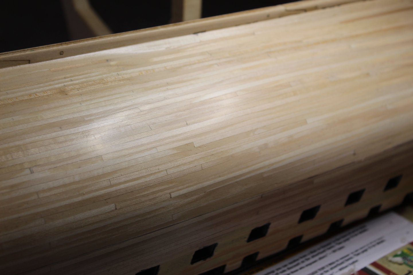
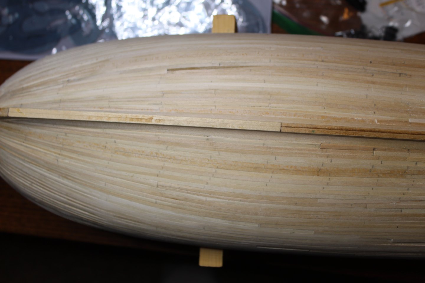
After a week of sanding during the evenings, here are the results (after sealing and steel wooling): I was very pleased with the results - remember, I'm a relative newbie to this.

-
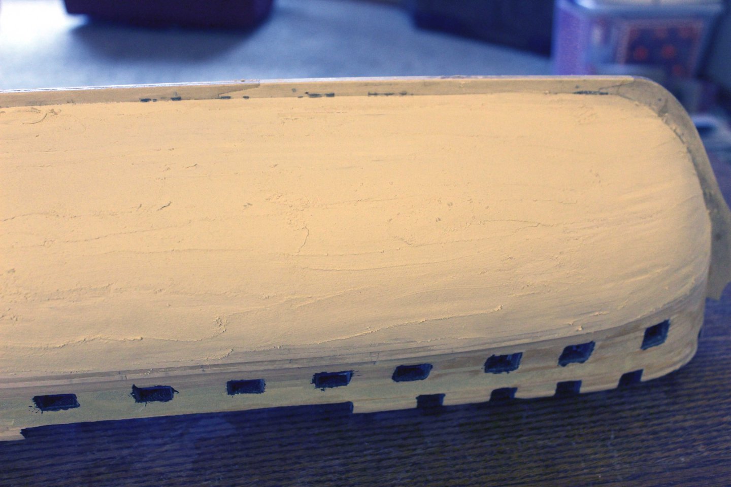
I liked how things turned out, but it was obvious that there was need for some filling of low spots, etc. So I applied a layer of filler I was hoping that this wasn't a huge mistake, but it was too late at this point. Once dry, I began sanding, and sanding, and sanding.
-
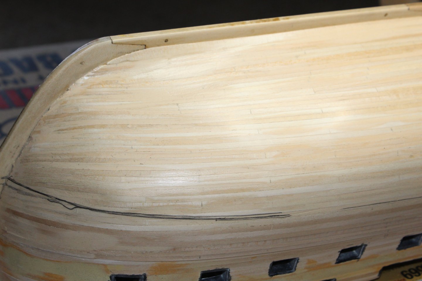
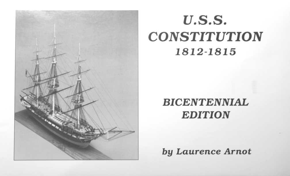
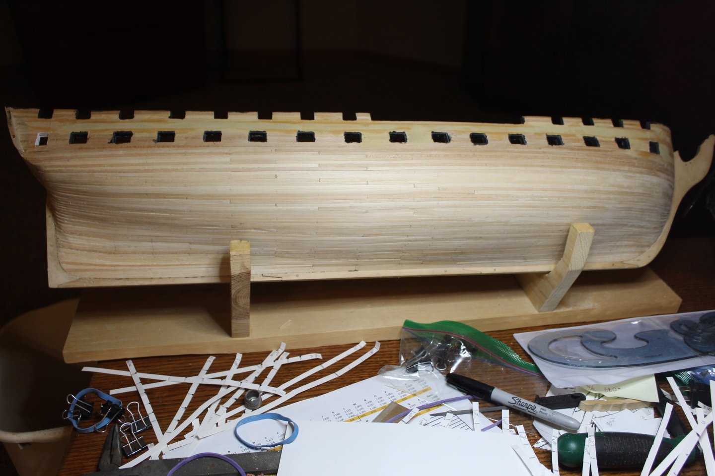
Well, I promised photos - here we go. First off, I purchased BlueJacket Constitution Manual and Plan set because it focuses on 1812 version of Constitution. I appreciate all of the historical information provided within the covers, and the plans as well. And here's proof that I have completed planking:
-
 bthoe reacted to a post in a topic:
USS Constitution by mtbediz - 1:76
bthoe reacted to a post in a topic:
USS Constitution by mtbediz - 1:76
-
Amazing work Jon! Really shows how model shipbuilding makes one think outside the box!
-
HI all, Just a quick update to let you know that the planking has been finished, and I'm working on cleaning it all up (filling where needed, smoothing it all out). I'll be providing photos shortly. The Holiday season shut down the shipyard for a while, and it took a bit of self-goading to get things back in operation. Since this isn't the first time it's been like this, I'm guessing it will be the norm. During Thanksgiving and Christmas, there were just too many little ones running around to be safe with sharp tools and a fragile ship lying about, so it all goes into the basement where it will be safe. Anyway, she's back out and I am working on her. It looks a lot better than I had expected, given my little experience. I give a lot of credit to all you experienced modelers out there who provide your wisdom to us newbies! Thanks a lot!! Hi @kmart, welcome to the build. I like your "my interpretation of 1812 version", as it gives us leeway to interpret things as we see fit and not toss and turn all night long worrying about how to do things "absolutely right". I was in that boat for quite a while at the start of things and am a bit more relaxed about it now. I get more sleep this way . Best to you all for 2025! I'll be checking into all of your build logs to see where you all are.
-
bthoe reacted to a post in a topic:
USS Constitution by mtbediz - 1:76
-
USS Constitution by mtbediz - 1:76
bthoe replied to mtbediz's topic in - Build logs for subjects built 1751 - 1800
Hi Mustafa, Hopefully these will help.


-
bthoe reacted to a post in a topic:
USS Constitution by mtbediz - 1:76
-
bthoe reacted to a post in a topic:
USS Constitution by Der Alte Rentner - Model Shipways - 1/76
-
bthoe reacted to a post in a topic:
USS Constitution by Der Alte Rentner - Model Shipways - 1/76
-
bthoe reacted to a post in a topic:
USS Constitution by JSGerson - Model Shipways Kit No. MS2040
-
bthoe reacted to a post in a topic:
USS Constitution by JSGerson - Model Shipways Kit No. MS2040
-
You're most welcome, Peter.