Steve20
-
Posts
168 -
Joined
-
Last visited
Content Type
Profiles
Forums
Gallery
Events
Everything posted by Steve20
-
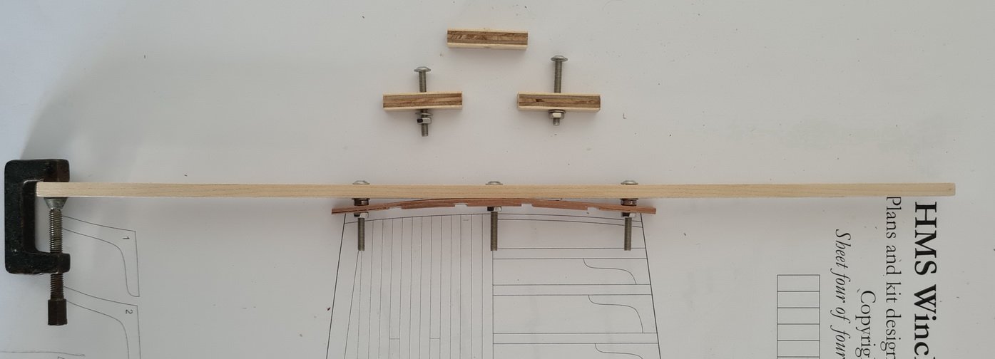
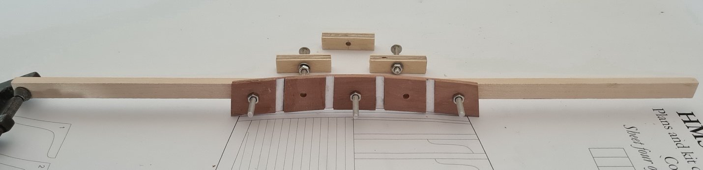
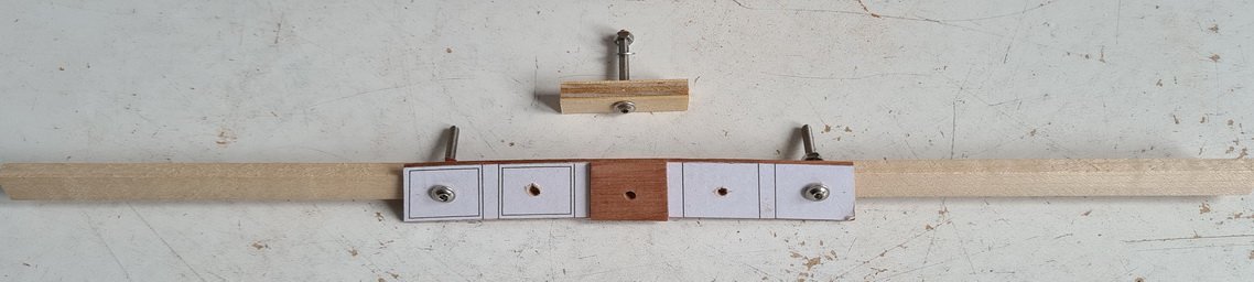
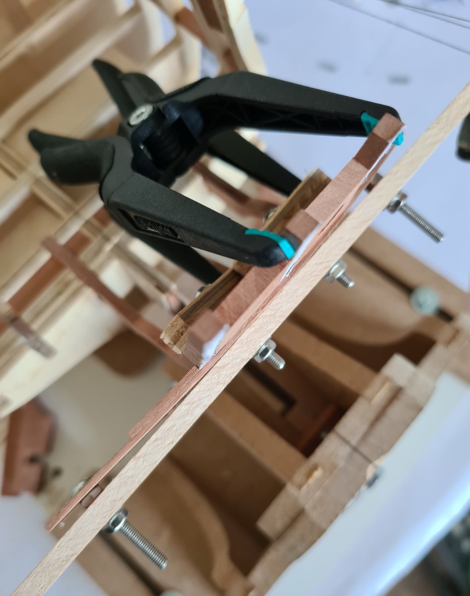
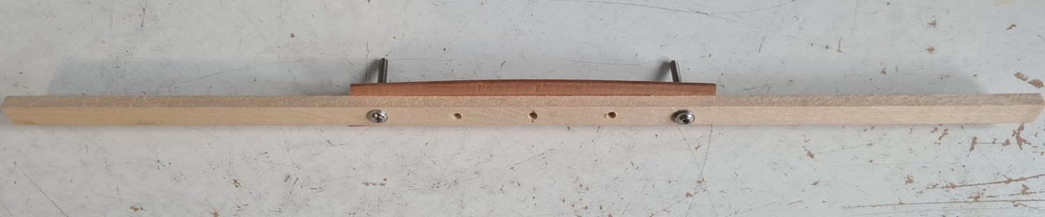
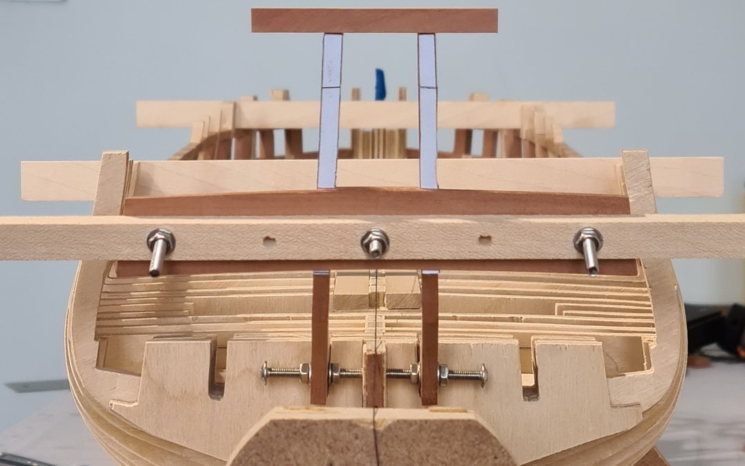
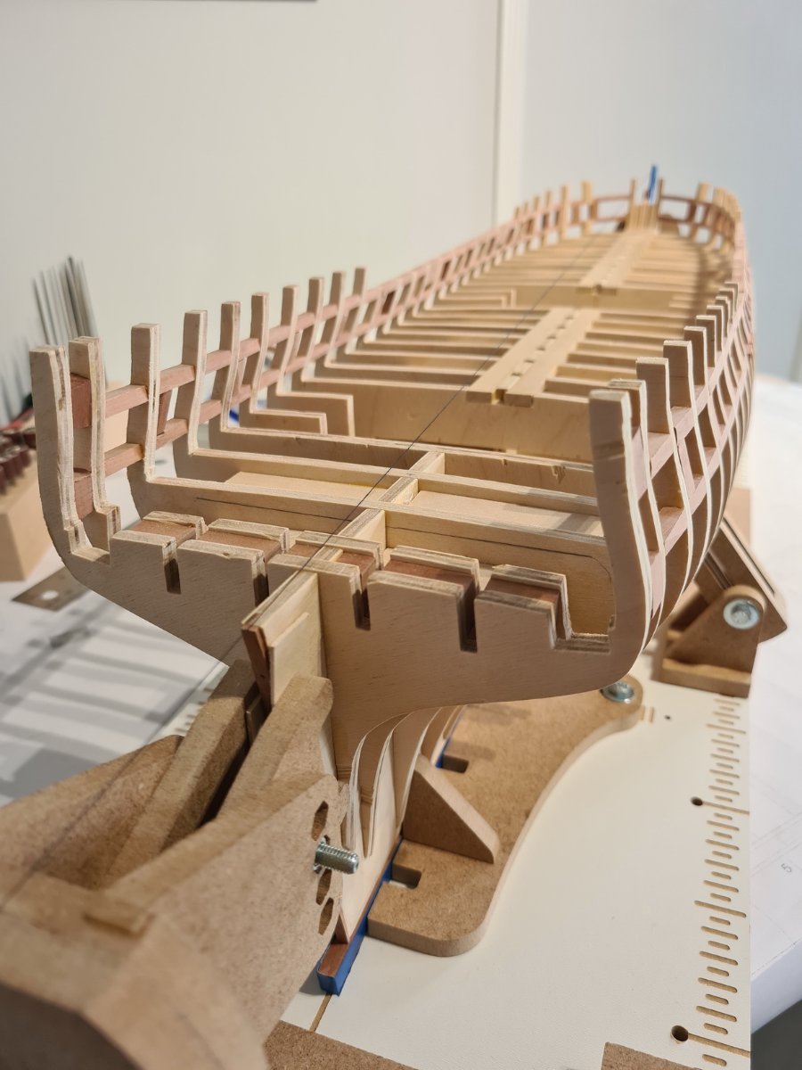
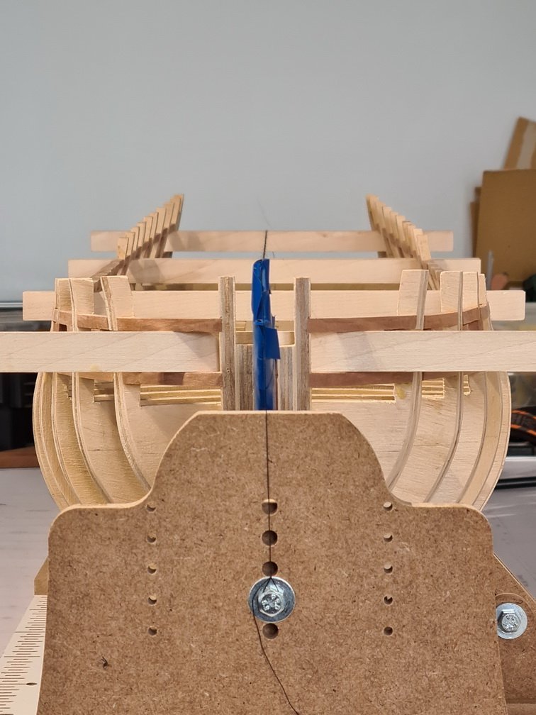
Same as for the bulkheads, my stern frames are not as good as the laser cut ones, so I drilled a 1/8” hole in the bottom of each ‘A’ frame and put a 1” long bolt with a couple of nuts on to fine tune the positioning and hold it. I also made a jig to aid stern frame positioning. I used a piece of 3/64” Pear the width and height of the five stern windows and pasted the corresponding paper template inside of it. I glued the window spacers to this as needed and drilled 1/8” holes through each of them. I shaped the Pear and spacers to the curve of the transom by attaching it to a 13” x 3/8” x 7/32” strip of Sycamore and adjusting 1/8” nuts and bolts positioned at the middle and each end of it.
-
Where a placement of a gunport port sill was more difficult, such as at the bows, I cut a slot to fix one end (I think it’s called a dado joint) and then I just need to concentrarte on positioning the other end only. I thinned down some of the inside framing as I went along to make it easier for me later-on.
-
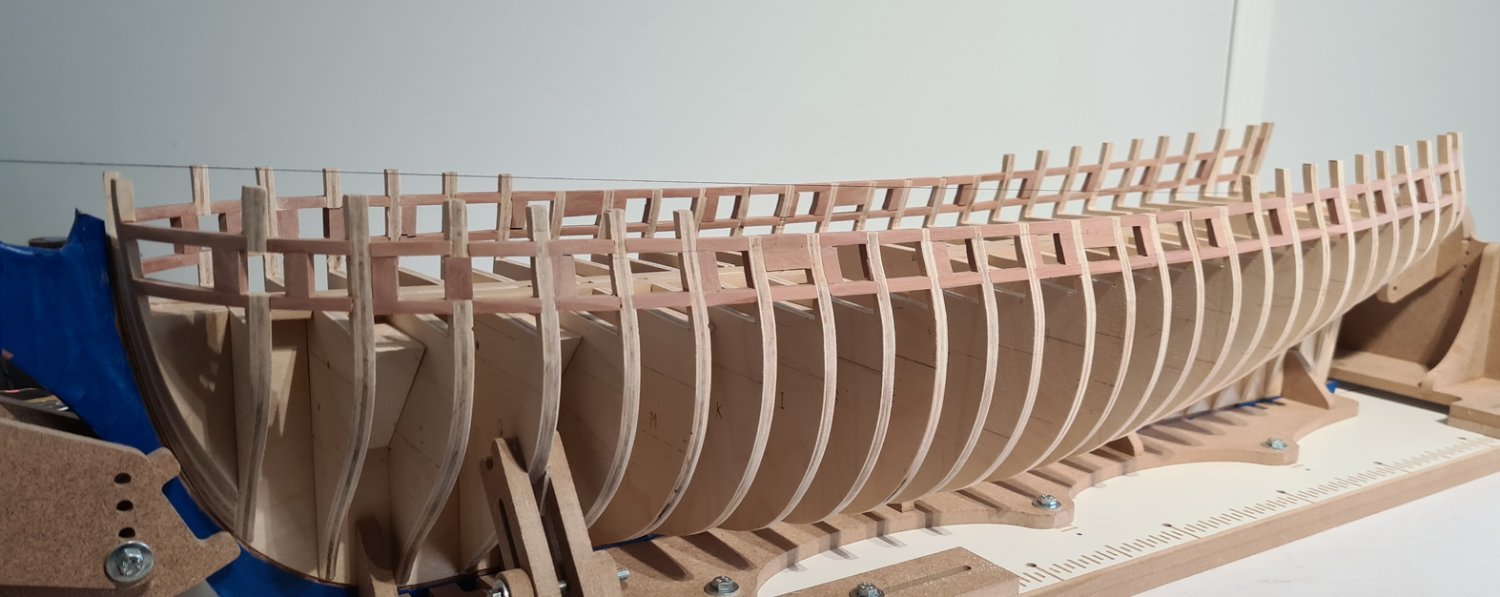
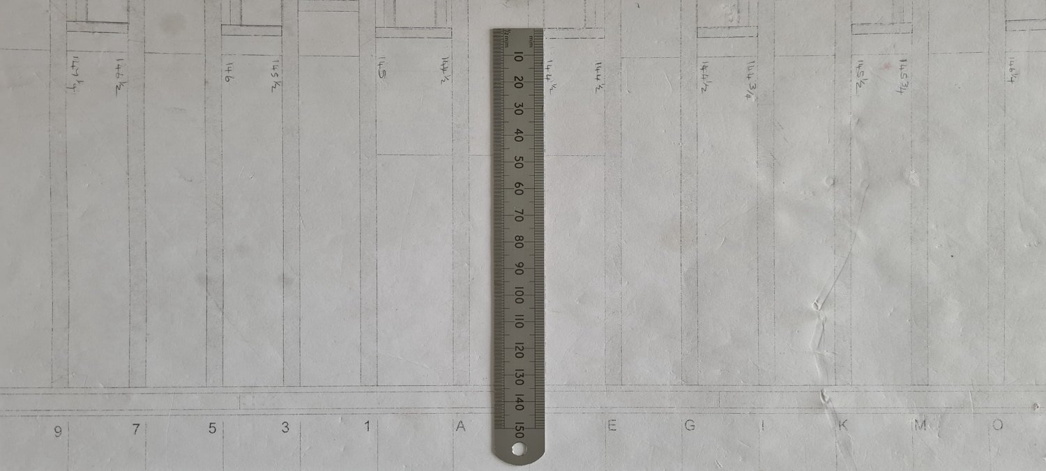
To position the port and starboard sill battens I again used the bottom of keel to top of sill measurement for stem, stern, and bulkheads ‘C’ and ‘E’, and marked these on the model. I pinned the battens at these three points, then as Chuck suggests, used the run of the battens to position the rest.
-
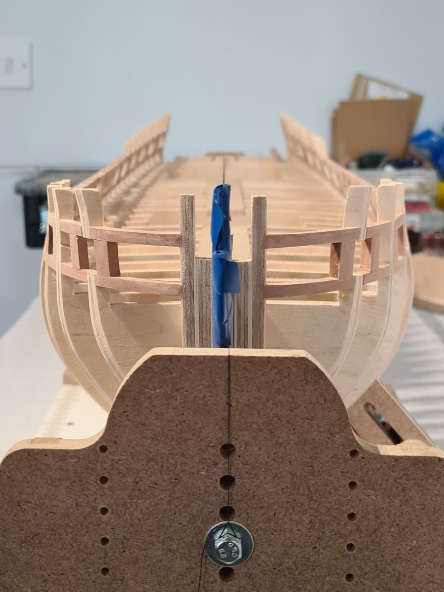
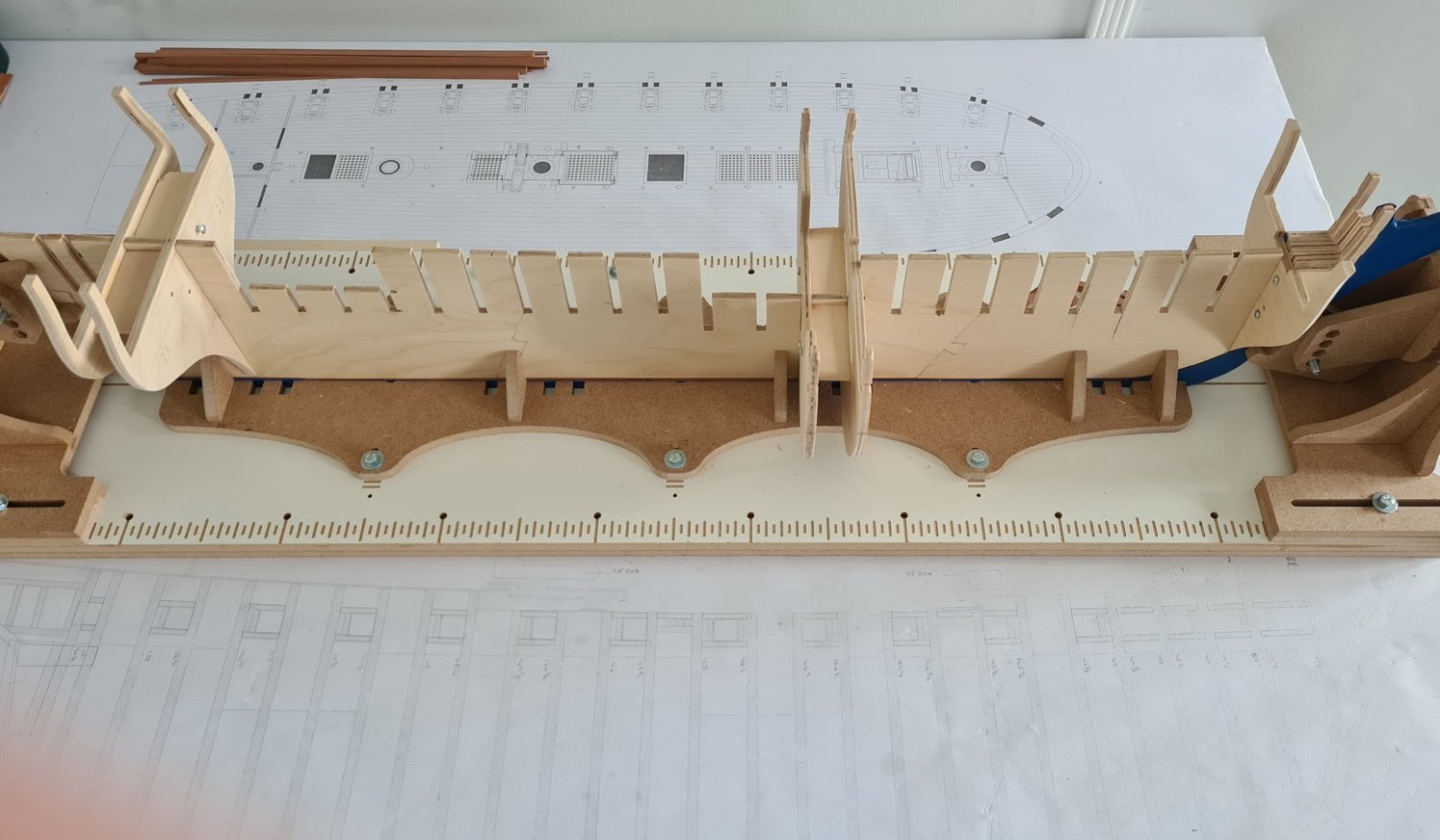
I’ve finally moved on to assembly of the bulkheads. I saw a Hobbyzone build board advertised and since the forum reviews on this are positive, I went ahead and bought it. My bulkheads are not cut very good and I found some of them were loose after I squared and levelled them, therefore, I put fillers between every other pair and assembled them two at a time. I’ll also have areas to pad out later, which I’ll deal with as I progress. My (three) key points of reference for assembly were the stem and stern bulkheads and the bulkhead in the middle as measured by the lowest gunport. Taking the height of lowest gunport sill from bottom of keel this proved to be bulkheads ‘C’ and ‘E’ so I positioned these bulkheads first and worked fore and aft from ‘C’ and ‘E’ bulkheads in the middle. Although I levelled and squared every bulkhead to the build board, I also checked that each was true to the stem, stern, and middle bulkheads and a string line I centred on the stempost and stern.
-
That's a lot of detail in the rudder, Glenn. Really impressive.
- 840 replies
-
- 2
-

-
- winchelsea
- Syren Ship Model Company
- (and 1 more)
-
Beautiful build, Jim, and a very nice base too.
-
Your comment much appreciated, Frank.
-
Thanks, Glen, but if I can one day build a model half as good as you I will be very happy. Also, I owe you a big thanks for posting the drum sander pic you made for the micro mill, it's a brilliant idea. I hope you don’t mind me copying it as I have now made one.
-
Thanks James, but master model maker I am not. I’m learning from everybody else here and the standard of work I see in their build logs is so high that it’s making me try very hard.
-
Thats an incredible build and it looks really, really good.
-
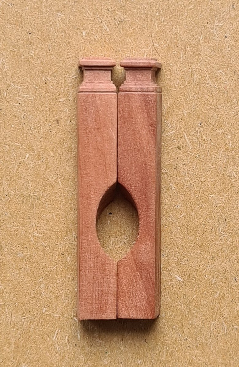
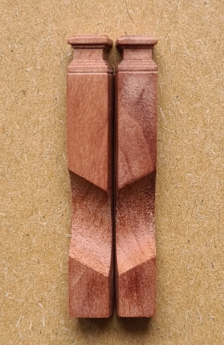
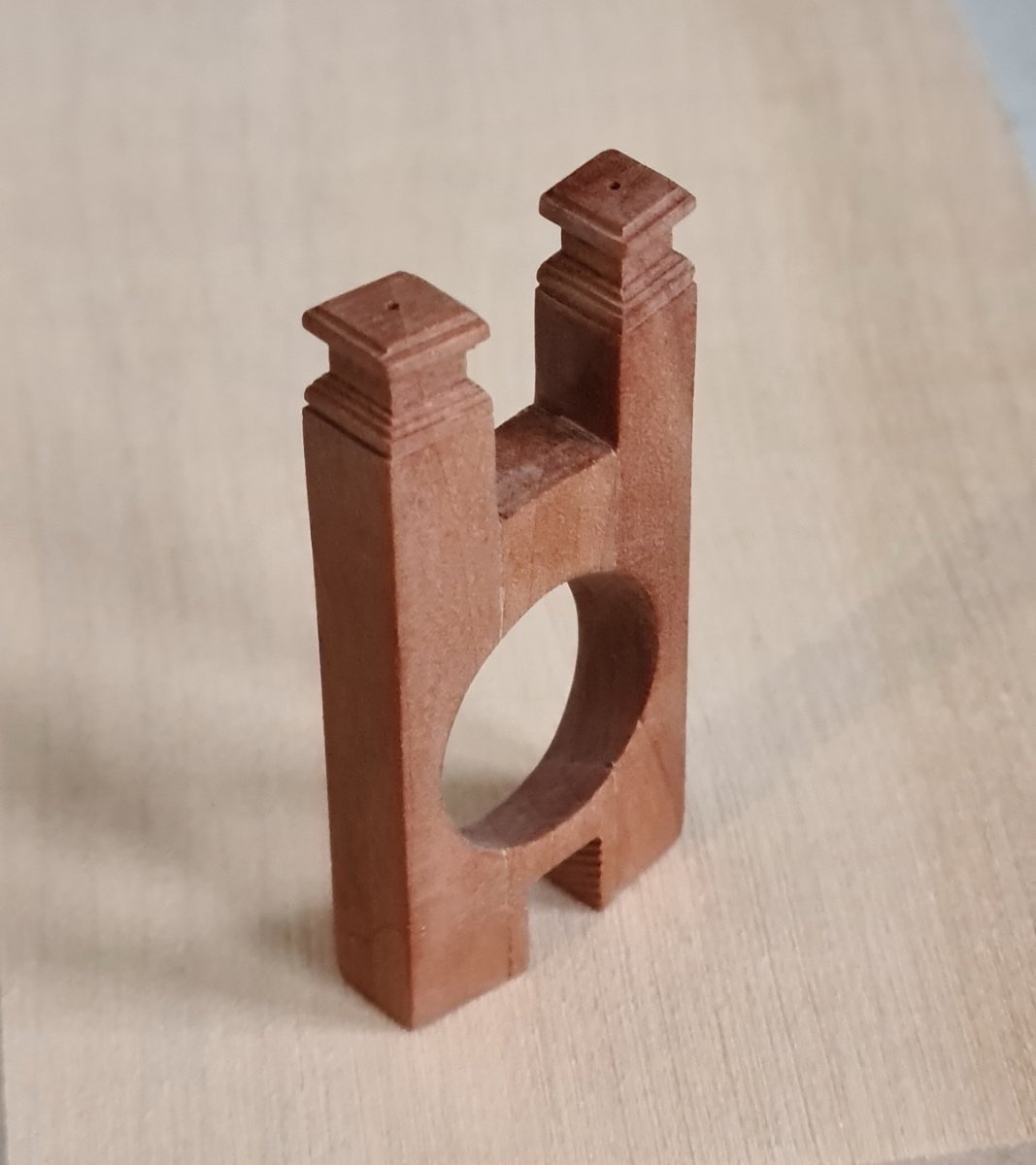
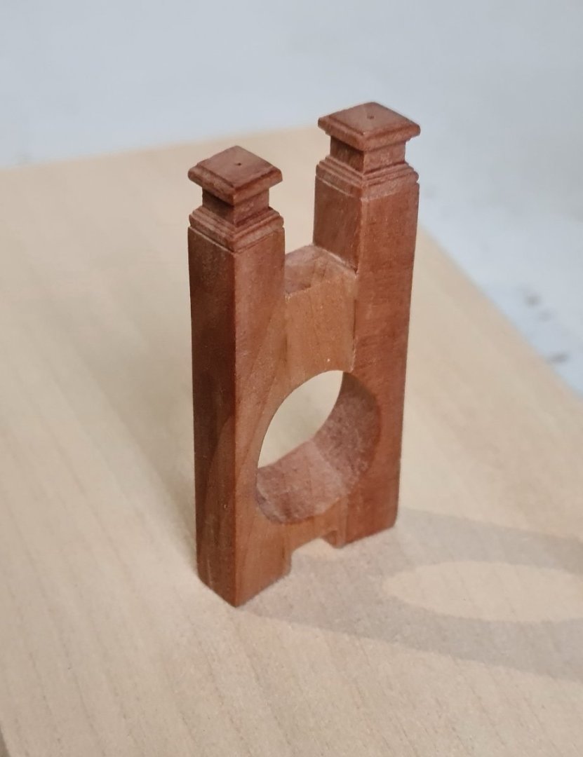
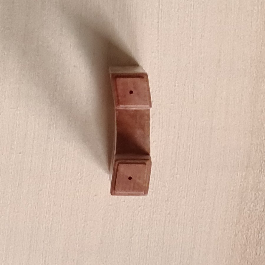
Thanks JJ, I drilled two 13mm (33/64”) holes at 30-degrees in a piece of ¼” Pear then sliced the sides of the first hole vertically 9/32” wide. I sanded the 9/32” down to ¼” but at an angle to get the rhombus (I looked that up). I then used a micro mill to shape the tops of the timbers. I sliced the second hole horizontally to obtain the top and bottom pieces that sit between the two uprights then cut these to the correct width. I found it easier to assemble the bollard timbers by making the bottom piece in one rather than slicing off two filler pieces, and to accommodate this on the model I cut the fore part of the bulkhead former down a little. The micro mill is a Proxxon MF70, which I only recently bought, and I wouldn’t be without it now. Its small size really limits the accessories that can be used but it’s ideal for indoor use.
-
Bollard timbers made. I'll put these to one side until needed.

-
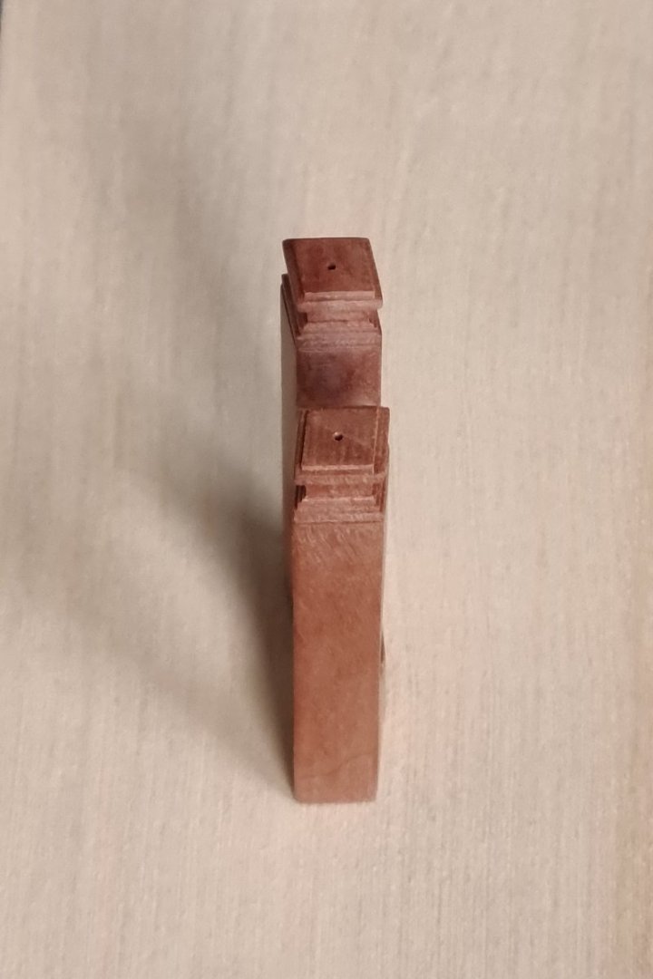
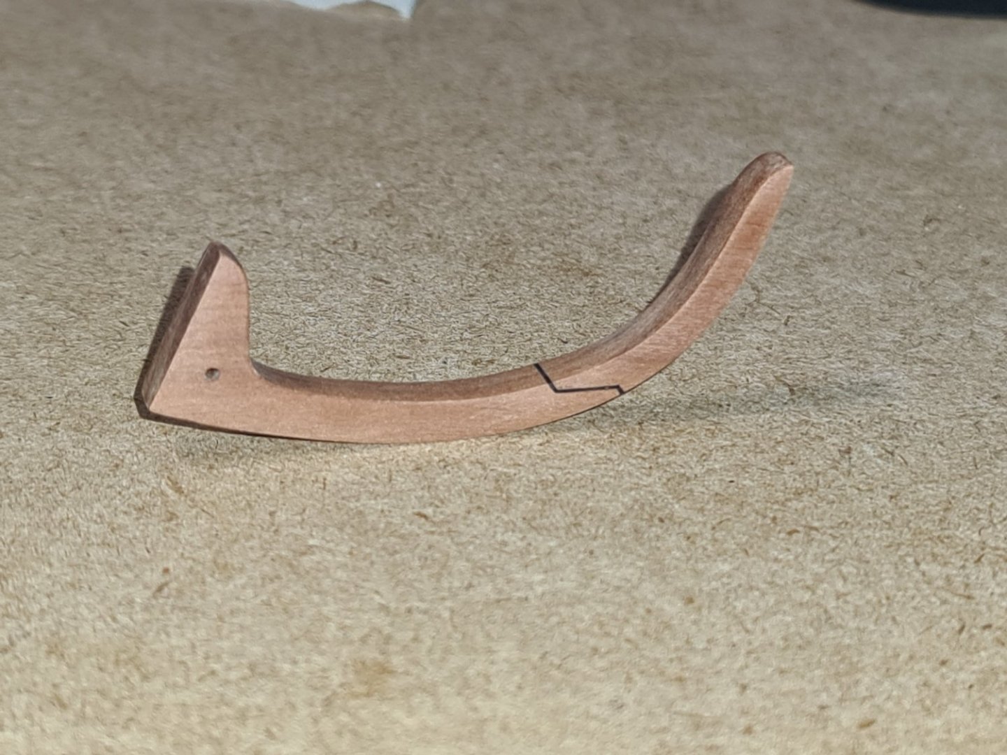
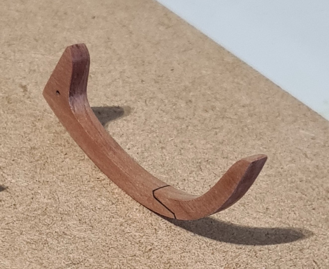
Gammon knee now finished. I am getting better at this.
-
Thanks for the advice, Glenn. The sill lines are particularly essential for me as my bulkheads are not accurate at all. These were my first attempt and I really should make them again, but I'm also dissastified with the stem I've made and I'm sure it will be the same with the stern, the planking and so on. I'm on a continuous learning curve here and improving slowly, so rather than repeatedly going back on myself I decided the best thing to do is finish this model then maybe make the Winchelsea again. I owe a lot to the many people here for their advice and their build logs showing how to do things, and particularly to Chuck for putting this project together. Without it I would have been building a kit and learning nowhere near as much.
-
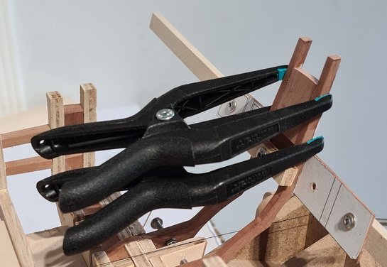
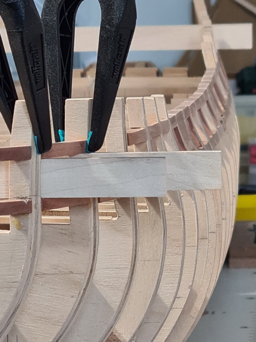
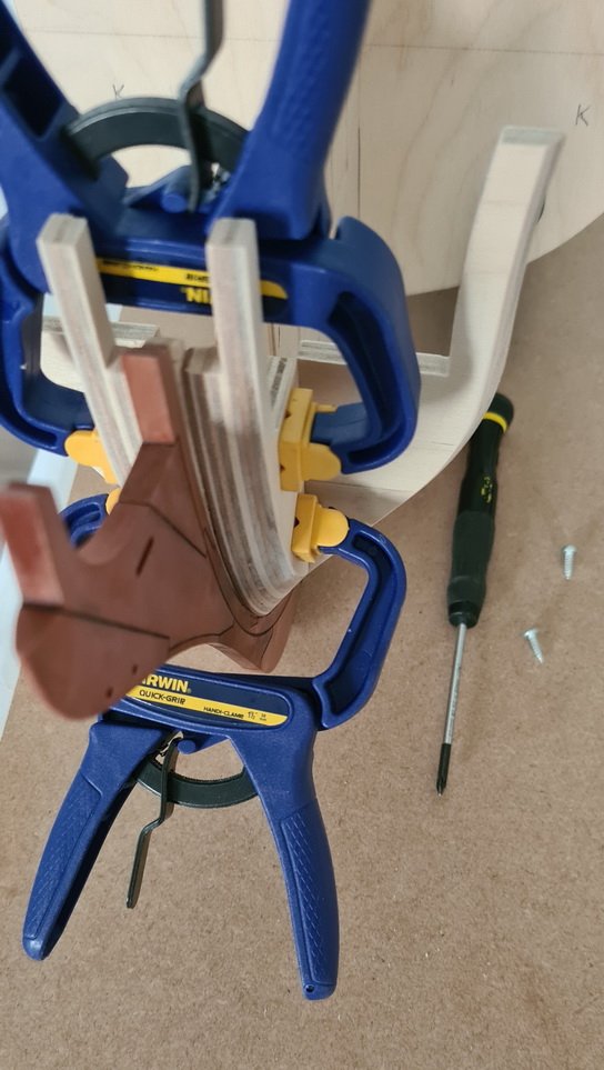
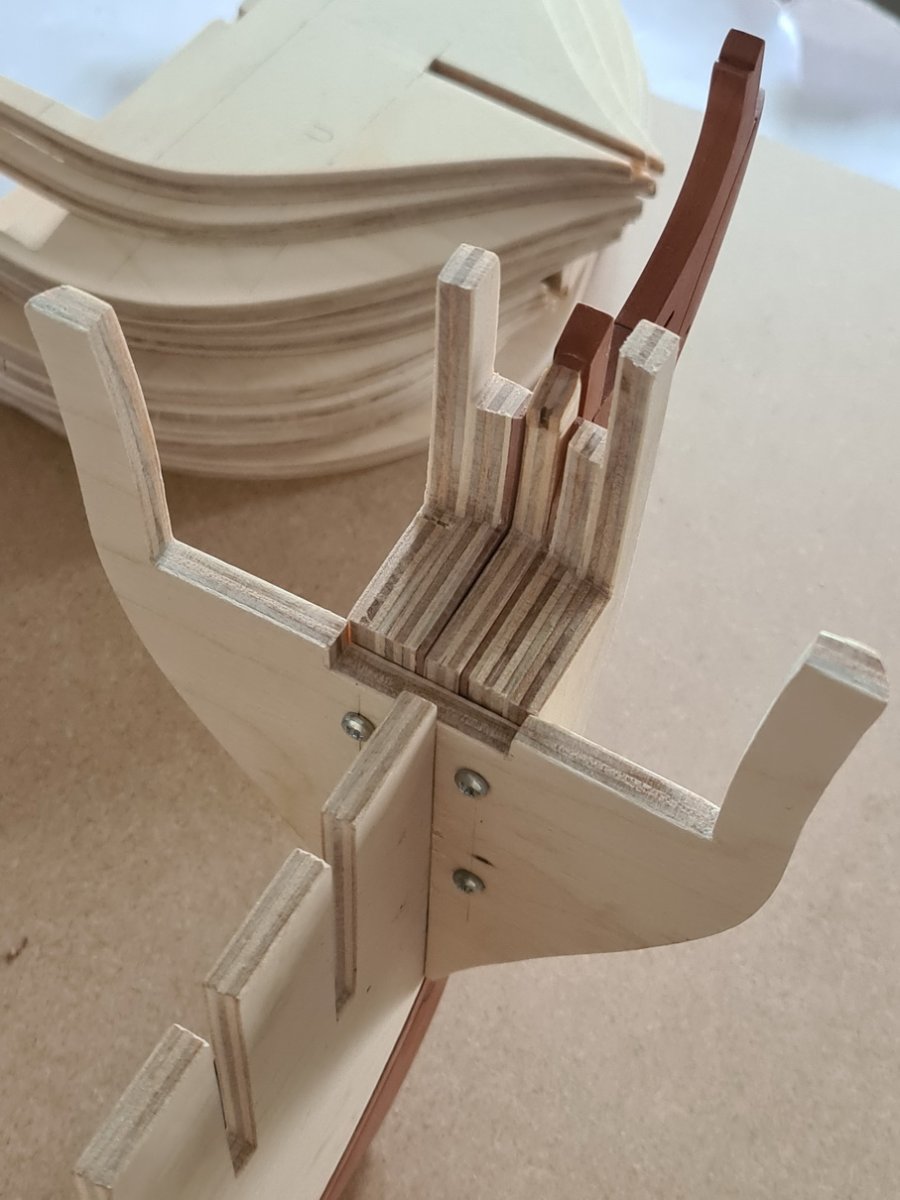
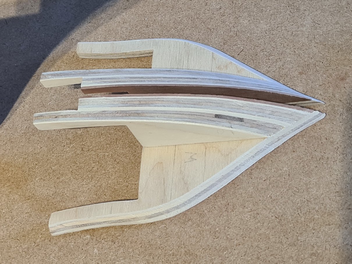
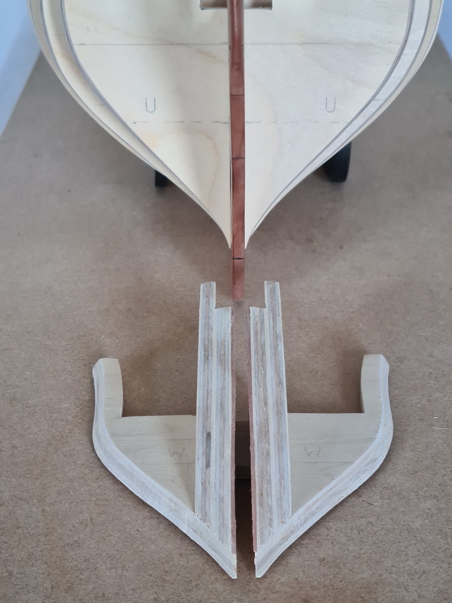
I pre-drilled four holes in the 'W' bulkhead and secured the bow fillers with 10mm long self tapping screws. I haven't applied any glue yet. The assembly sits firmly in place but it is easy to remove for fairing. If I happen to make a bad mistake on a piece I can just undo the screws and make another. When the time comes to glue everything in position on the bulkhead former the screws will hold the bow fillers tight against the 'W' bulkhead better than a clamp will. The screws can be removed and discarded after gluing.
-
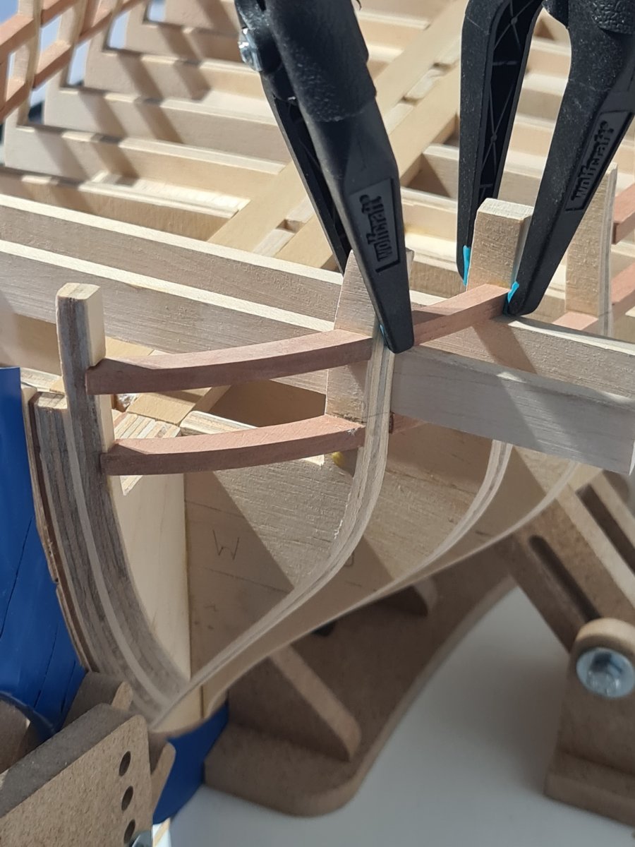
Good point about paint adhesion, Jim. I’ll bear that in mind for the future. Right now, I’m working on bulkheads in preparation for assembly to the bulkhead former. I particularly want to simplify the fairing of the bow area and minimise risk of damage to the Pear. I’ve found the below method of pre-assembly to be very useful: