HOLIDAY DONATION DRIVE - SUPPORT MSW - DO YOUR PART TO KEEP THIS GREAT FORUM GOING! (Only 75 donations so far out of 49,000 members - C'mon guys!)
×


robbl
-
Posts
74 -
Joined
-
Last visited
Content Type
Profiles
Forums
Gallery
Events
Everything posted by robbl
-
 Not quite parallel as much as something to work on while the main project has things drying, or if I am a bit tired of some repetitive task or stuck onsome concept. So if a build can be slower than my Blanche, la Salamandre will be that build
 -
Looking at the full profile pic you put up, I had a thought that you could practice doing a cut away on the hull to show some internals
-
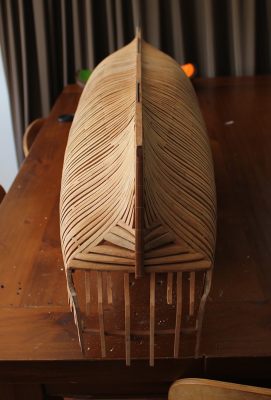
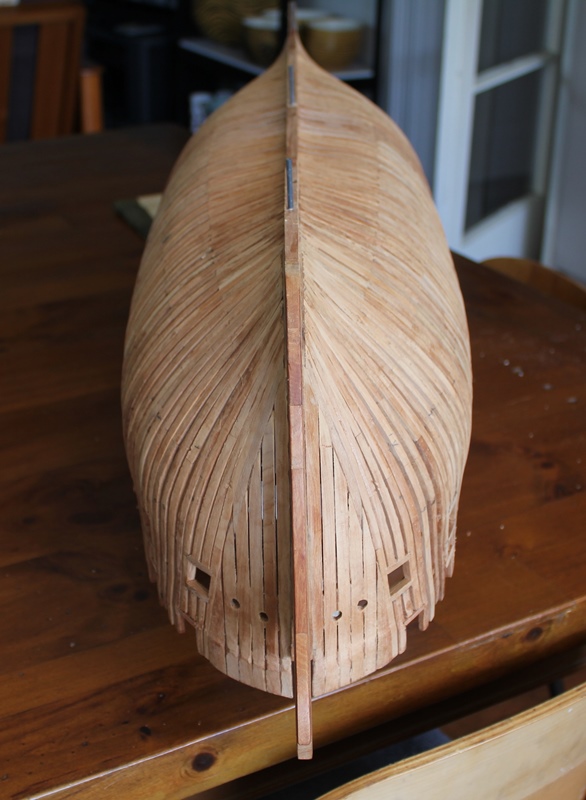
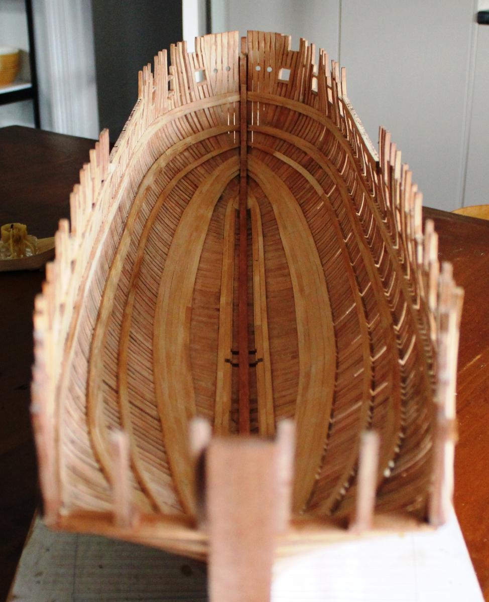
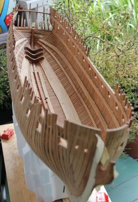
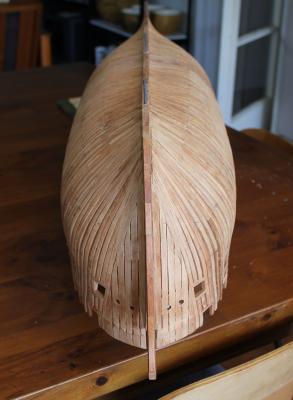
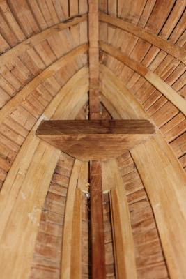
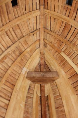
Thanks for the comments guys. A little progress..... I have fitted the 3 crutches aft. Each of these was roughly cut based off cardboard templates, then sanded, sanded and finally sanded some more until they fit ok. There is "air" between the ends of the crutches and the frames which I am comfortable with, however I am considering slipping some planking under them. Next on the agenda is fitting the lower hooks at the bow and the foremast step. I am also experimenting with some wood to build some of the internal structures, so hope to have some progress shots of that soon. So, feeling that I was close to finishing the external fairing and then I could charge (figuritively) ahead with internal work, I took her outside for a bit of a cleanup. Started sanding lightly with a fine sanding stick ... moved onto a rough paper .... ended up using a wood rasp and chisel. Ok then, perhaps there are a few more hours of sanding to go then ... I can say that I am happy with my decision to fit the deck clamps and gun ports before doing the external framing, as it has provided a lot of strength to the hull. I have been able to use a powered hand sander and twice knocked her against objects while carrying her outside for sanding without any frames getting damaged. And since I get quickly tired of sanding I started a little side project (admiral thinks I have the attention span of a gnat) Cheers all Rob

- 82 replies
-
- 11
-

-
Mark, tough decision but I am looking forward to the new version as I found your build helpful to follow. I particularly like the list, 2 and 4 being my personal favourites Cheers Rob
-
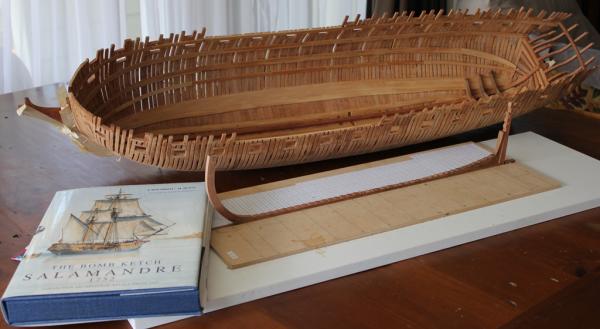
Top right corner of the image, lying on the floor is that very book. Apart from being a good modelling reference book, it is an excellent read time and again. Our libraries will all look the same
-
Overestimated my floor/table space 31 sheets is the correct number. I have opened up some representative sheets and left the rest folded in the stack. One of the books is in there for scale. Cheers Rob


-
Yes I do, but then again I like a lot of the other Ancre subjects as well. The 74 volumes are great reading, and also a good reference for how some of the other Boudriot subjects are built. I'm not sure I could do a 74, but I love the ones being built in the logs here. Looking forward to your log now too
-
31 sounds close to the number so maybe it is the same pack as sold by ancre And looking at taubman I'd say it definitely is If you want I can spread them out when I get home and take an overview photo a couple of hours from now.
-
Not sure about the Taubman sorry. This is the set I mean... Les planches - Français - 42 € On ancre.fr under.... http://ancre.fr/Product.aspx?ID=3702234&L=EN
-
I should have said, the pack of plans are the plates from the volumes in sheet form. Cheers Rob
-
I did the same, got the volumes 2nd hand apart from v4. So I ordered that from Ancre and I saw the plan pack listed under the books on the product page for the 4 volumes(ie not as a seperate monograph) The pack is the size of a moderate A4 size paperback, so postage is not too bad.
-
John - did you get the plans as well? They sell them as a seperate package on the Ancre site. I had got the books then ordered the plan package later. PS. The 74 is based on one that would be found in the French fleet around 1780 (from the Forward in Vol 1) Cheers Rob
-
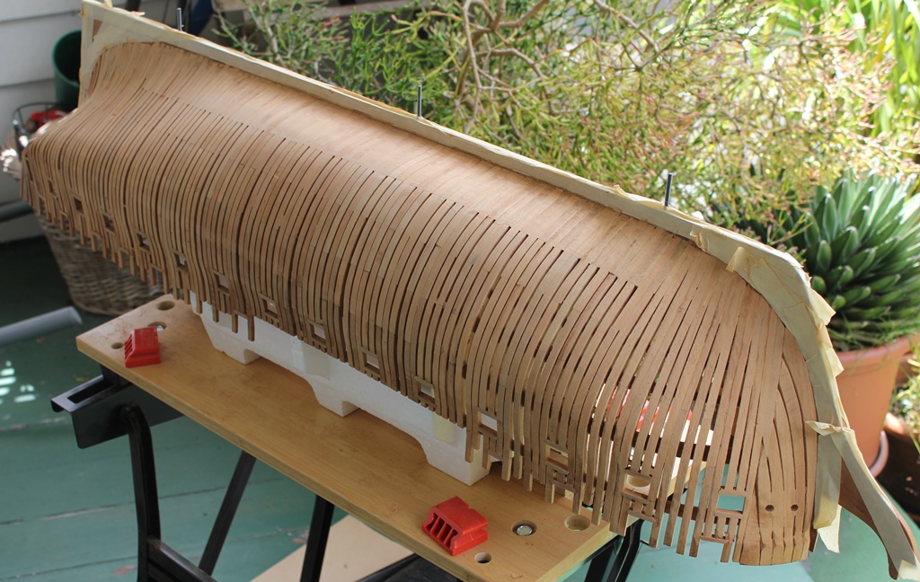
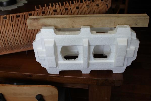
Håkan, if I told you where I found the time, there would be less for me! Mini update ..... I finally released Blanche from the building board she has been bolted to for so long. It was with considerable relief that I didn't see any sag or hogging. More relief was due to the fact the whole thing didn't spring apart ...... So to avoid breaking off all the tops, I built a little support from some polystyrene glued to some timber .... Which will be clamped into my portable workbench for external fairing. I quickly took it outside to create some dust and the arrangement worked well. Less pleasing was seeing how much I have to do, as my early woodwork leaves something to be desired .... this is going to take a while. Still, it was nice to see the undersides after all this time. She looks a bit like a beached whale.... Cheers Rob


- 82 replies
-
- 14
-
-
Hi Egen I was catching up on your build, and it looks very good indeed. Your progress is really impressive and I am looking forward to the next installment Cheers Rob
-
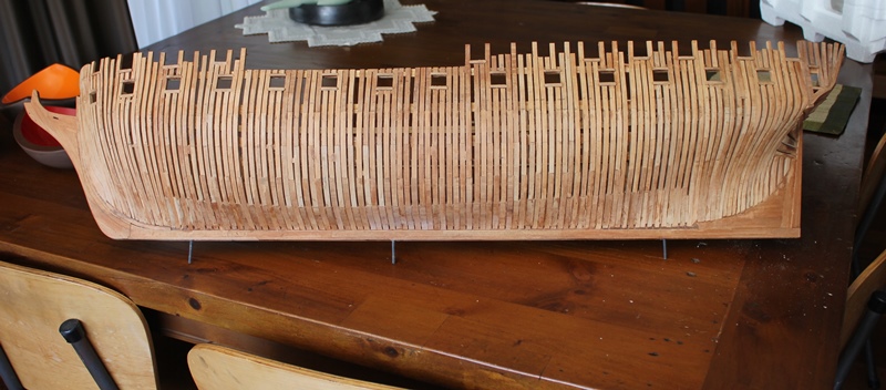
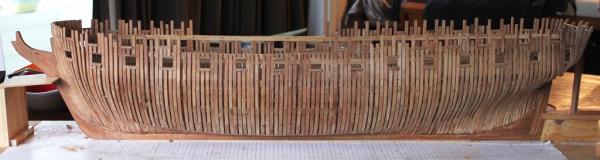
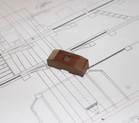
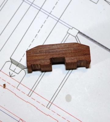
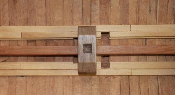
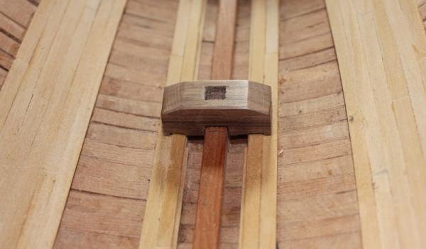
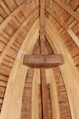
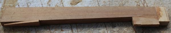
Hello all After a long hiatus, I felt guilty enough to pick up some tools and do a bit of work on Blanche. Things have been a bit busy, and will be for a while to come, so I am only doing small bits and pieces for the foreseeable future. When I last posted, I was doing deck clamps and gun ports to stiffen up the hull and strengthen the framing, as I have not yet removed her from the build board for external fairing. As a result, the external side view has not changed much except for the addition of the tops of several frames, and port sills for the forecastle and quarterdeck. Internally, I finished putting in the deck clamps which I had previously started, and repositioned a couple that looked poorly aligned. I have also done the fore and main mast steps, and I think they look ok for a first attempt. First is the main mast step.... Then the foremast step...... 1st - the rough shaping was done by copying the plans for the frames on which it rests (R to S), and cutting a slab of wood to the shape of the inside of those frames. Then I sanded the block so the fore end matched the inside shape of the forward frame. After that, I used my little mill (Proxxon MF70) to cut the groove for it to sit over the keelson, followed by more sanding and shaping. Then finally I used the mill to create the slot for the mast. The steps, and the hooks and crutches that I will do soon, are all from old Totara wood that was once fence posts and is much darker than the Totara I used for the frames, which was old flooring boards. The keelson is from a slab of Totara, and is a slightly richer colour than the frames. Clamps and thickstuff/planks are Kauri. So that's my catch up as it stands now. Next work will be crutches and hooks, and maybe try and do some internal structures. Cheers Rob
- 82 replies
-
- 12
-
-
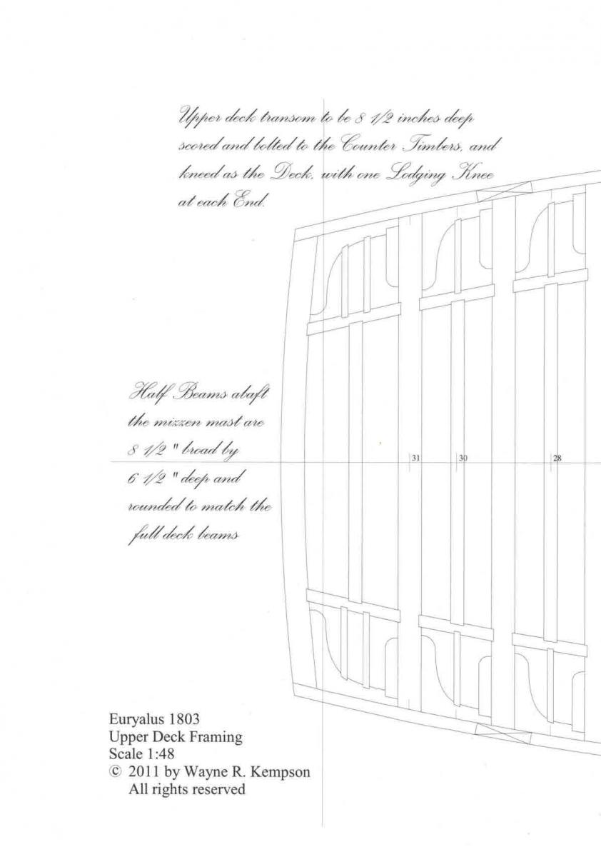
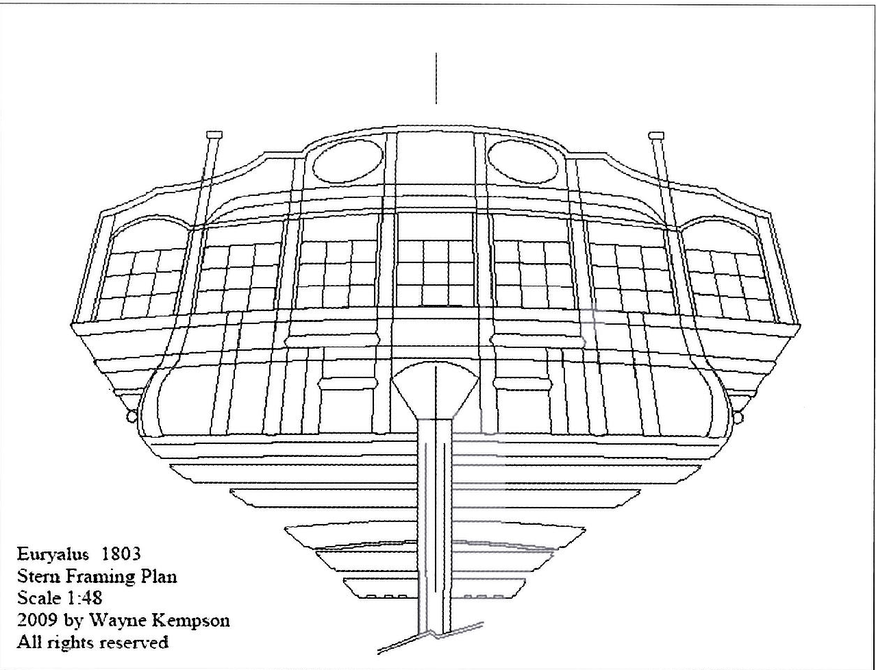
My thoughts are (and they could be wrong ) Upper Deck Transom: top of this transom should be at the same level as the top of the upper deck beams so the deck sits on that transom or a rabbet in the transom. Slightly higher as the deck slopes up, and if this transom was as deep as the beams, it could sit on the upper deck clamp. Seat above the upper deck transom is roughly at the level of the lower sills of the main gun ports, above line 3 I think. Quarter Deck transom: the quarter deck fits into the rabbet of this transom so it should sit at a level for the quarter deck to run into it - line 5 I think Transom of the Quarter Deck: about 6 in your drawing Cheers Rob
-
Also, the side counter timbers might need to be longer Egen. Cheers Rob
-
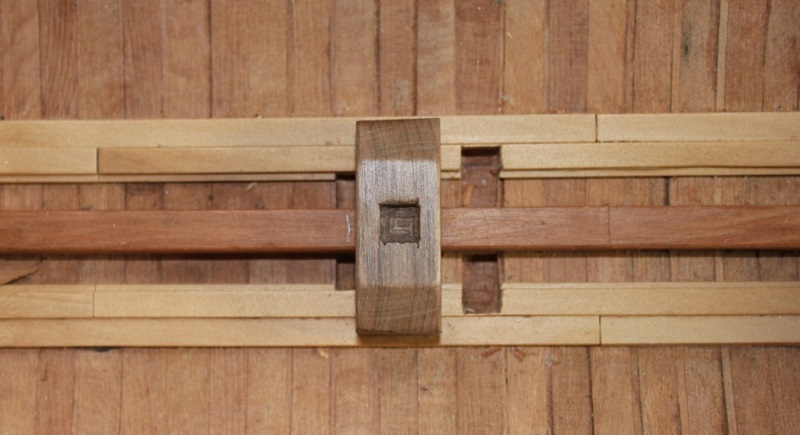
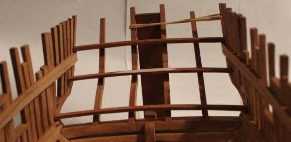
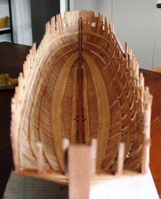
In your picture, the 4th frame in from the left is short as I expect it to be. Sorry, I didn't count the side counter piece before, my fault Is the lower of your red lines a timber on the outside of the stern or a guide line? Below the red line is the upper deck transom and above it is the seat, then the quarter deck transom and above that the "transom of the quarter deck'. Then the other smaller framing for the ports and around the helm port which look to be there on the left of your picture. I did some rough transoms and put them where I think they'll be going here: I don't have the shorter counter timbers in yet, and ignore the rubber band and wonky picture. My dimension for the upper deck transom is only 8 1/2 inches broad (4.5mm) (book says 8 but plans say 8 1/2) and 5 inches (2.6mm) deep, and your upper deck transom looks bigger than that. Yours looks to be 8 1/2 inches deep and perhaps 15" broad, which matches the upper deck beams? Looking again at the upper deck plan in V2, the drawing of the stern seems to match yours better than mine. So apart from my question about the dimension of that deck transom, and what the lower red line represents, the way you have it on the left of the picture (<-----) looks ok to me. Cheers Rob

-
Hi Egen The innermost short counter (3rd from the side) is shorter. here's two of the images from Vol 2: Ed T's Naiad counter is a good example to look at I think as well, although the dimensions of the transoms are different I think. http://modelshipworld.com/index.php?/topic/232-hms-naiad-by-edt-160-frigate-38-1797/page-9#entry13950 http://modelshipworld.com/index.php?/topic/232-hms-naiad-by-edt-160-frigate-38-1797/page-13#entry30660 Cheers Rob


-
Crackers, I use full size push sticks and hold downs where I can, or the featherboards. I had one look at that "spinning wheel of amputation" on the table saw and decided my fingers didn't belong near it. Mind you, none of these power tools (even mini ones) are fool proof - I managed to sand my knuckles on my disc sander once trying to get that extra .1mm ..... Apart from that, the featherboard can keep everything in a nice alignment for a good clean rip because you're not having to keep moving your fingers out of the way of the "cutting thing". There are some times when I will rip without a push stick however. If I'm ripping 1mm or less, say, and the board is a few cm wide, then I might just push the board with my fingers until the board is too narrow and they get "too close" At the point of "too close" , then a rip of half the length, flip the piece and rip the other half to finish the cut keeps the fingers well away from the blade. Regardless of all the scars I have from years of modelling knives (cut away from the thumb... pffft........ouch), I am frightened of any powered blade ever since the time a dremel cutting blade shattered and a piece embeded itself in the wall just beside my head. Cheers Rob (not the best OSH* spokesman) * Occupational Health and Safety
-
I often use the featherboards from Micro mark on my Proxxon FET when ripping along the fence. Those small pieces of wood travel fast and far sometimes, and the first time one hit me in the stomach was the last time I stood behind the saw. It also stops me pushing my luck holding the wood down with my fingers close to the blade. the featherboard attached to the fence works well, the one that sits on the table holding the piece horizontally works ok but I hardly ever use it. Cheers Rob
-
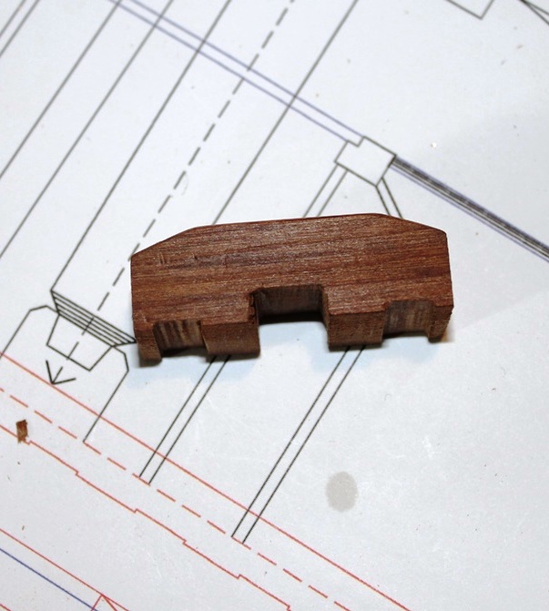
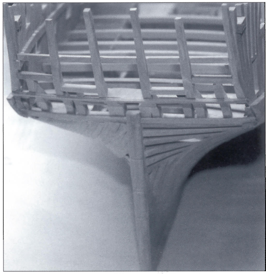
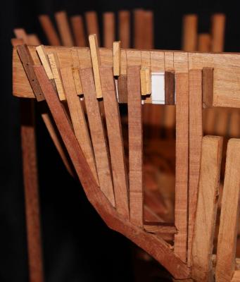
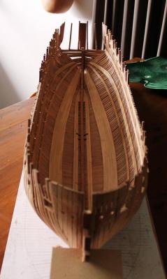
Thanks Egen, Clay, Wayne and Druxey. Egen, I thought I might add notes on building the stern area. so far. All the counter timbers were cut to the plan's pattern from 9" (scale) wood except the side counter timbers which I cut from wood over twice that thickness. These side timbers were then marked with the profile as seen from the stern and sanded to shape on the disc sander and a small drum sanding attachment. Then all were tapered to their correct dimension at their tops by sanding. The vertical piece of wood sticking up in the photos is on the center line and its width is the gap between the two center counter timbers at their tops. Once they were in place, the next tall counter timbers were set up with the appropriate gap at the top from the center timbers. Finally the side counter timbers were positioned using the little jig clamped to the last stern frames to get the angle and distance right. All these counter timbers sit in mortices in the wing transom, so the positions of their bases are fixed and the top alignment was the only issue. The filler timbers were all cut from the pattern of the top timber of the tallest aft frame (31 fwd) to get the right shape of tumblehome on them. They were then cut to length and fit into the jig. While doing this, I noticed (or had always known ) that the fwd fashion piece on one side was poorly aligned and needed too much pressure to be bought into line, and I was not surprised when it broke above the level of the wing transom. That was an easy repair. it was one of the first frames I had ever built and was consigned to the bin with due respect . Once the forward most two filler timbers are in place, the side counter timber was quite firmly in place, but the addition of the quarter deck clamp and transoms will strengthen it far more. Cheers Rob
-
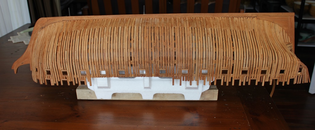
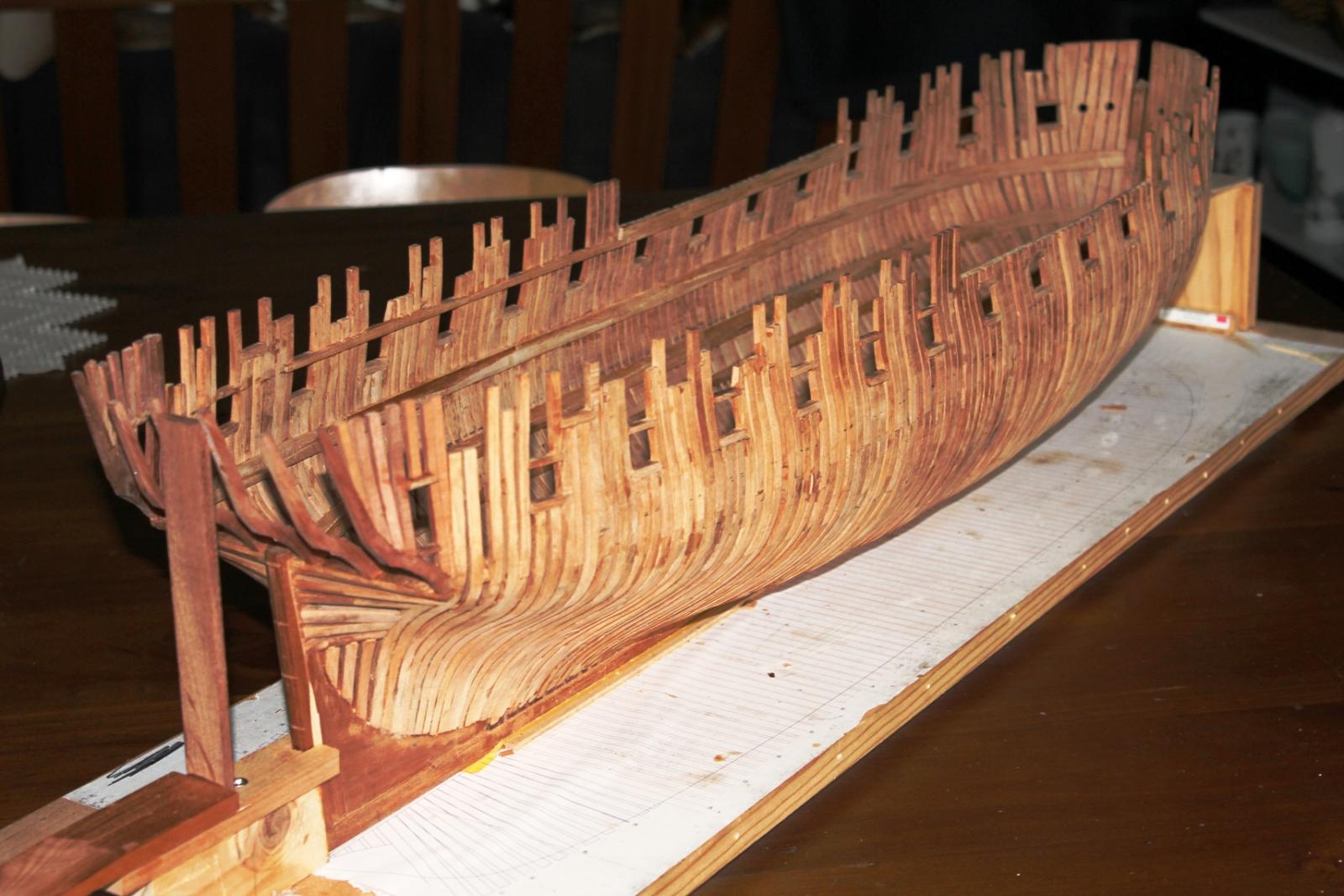
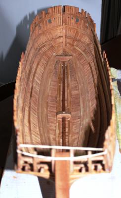
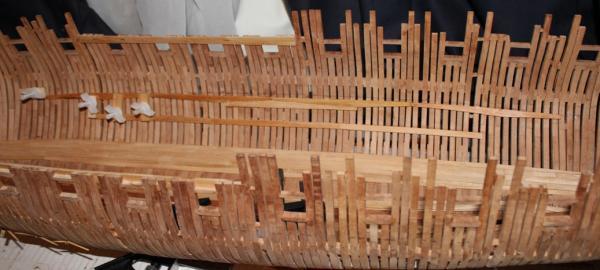
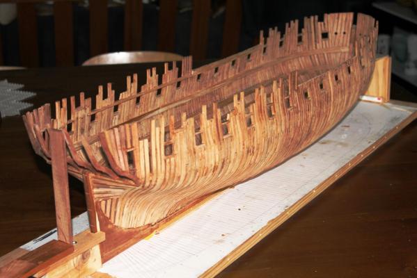
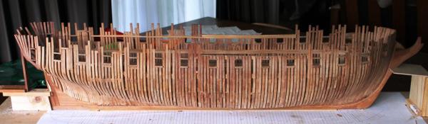
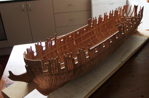
Well, long time no see.... Busy at work and home, and slack doing updates - these are my excuses. Also, there wasn't much visually happening so I just kept doing bits and not updating the log. The work that has been done is to strengthen the frames ready for external fairing. To do that I wanted to get the quarter deck clamps on, which then lets me put the tops of the frames on where there are gun ports. Once I decided to do that, I had to do the orlop and lower deck clamps and then the stern timbers. So I set to cutting top and butt planks using my table saw and two pieces of wood cut to the right angles as jigs. I glued a piece of wood to the end to serve as a pushing block, and two pieces to the side to hold the planks down and stop them climbing as they went over the blade. The results looked ok, and more importantly they fit. So I got the lower clamps done, then started on the stern timbers. To align the frames on each side up I cobbled together a plank with a copy of the plans of the tops of the frames, and glued strips of wood on. The frames then sat in that and were glued to the counter timber. These frames still need cutting down to their correct lengths, but I'll do that after strengthening with the transoms. So, now some shots of the whole thing. Still working on the quarterdeck clamps. Where they meet the strings of the waist I didn't put a proper scarph in, but simply cut a small scarph of one frame width to strengthen the joint. As I do these small tasks, I am removing the original spacers from between the hull frames as the clamps take up the job of keeping everything in place. This is proving to be harder than I expected, mainly due to the good quality glue , but they are coming out. Cheers all Rob

-
Nice structures Egen. That door looks fine to me. Cheers Rob
-
Hi Egen For the guns on the model, I think the most I could do is the carriages. I do not have a metal lathe and do not like casting. One of the companies I work for can do mold making and casting, and have said if I can do a master they could do the rest. I would certainly be interested if someone was going to do the guns. For a 1:12 scale version, I was thinking of trying to turn a barrel for each using my little wood lathe. Cheers Rob