Jules van Beek
-
Posts
56 -
Joined
-
Last visited
Content Type
Profiles
Forums
Gallery
Events
Everything posted by Jules van Beek
-
Technical drawings & Dutch shell first
Jules van Beek replied to Jules van Beek's topic in Nautical/Naval History
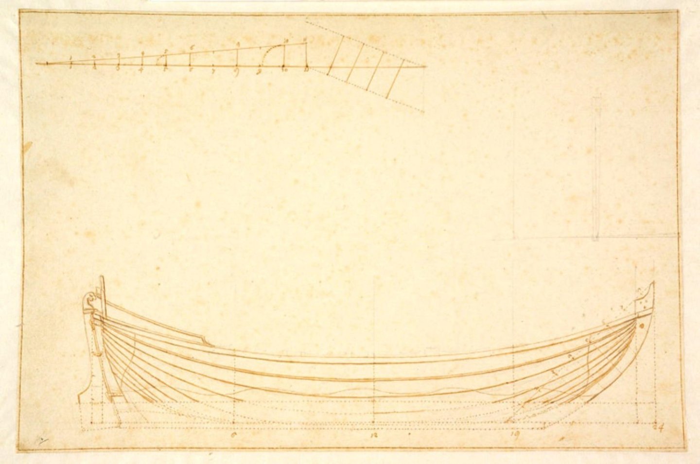
Hello Allan, Please don't take this the wrong way, but when you say in your first post in this thread that you "do question the knowledge of his father" based on what you see in a plate in a book of 1690, that to me is an interpretation, it is even a judgment. When you want to judge the work of father Cornelis Witsen, judge the work of father Cornelis Witsen. Because, as I tried to explain in an earlier post, when you look at the plate of the sloop in Nicolaes Witsen's book of 1690, you are not looking at the work of father Cornelis Witsen. You are looking at the print of a plate that an artist hired by son Nicolaes Witsen made by referring to the print of the plate son Nicolaes Witsen made for his book of 1671. The plate son Nicolaes Witsen made for his book of 1671 was made by referring to the work of father Cornelis Witsen, the original design drawings for the sloop. When you want to judge father Cornelis Witsen's work, judge his original drawings in the Scheepvaartmuseum; not the copies of the copies of his original drawings. That's also why I put you on the track of Kees Dik; he used the original sloop and boat drawings from the Scheepvaartmuseum to build his model sloops and boats, and write his book. Here is what Dik says about one of these drawings (in Dutch, my translation): "563. Top view of a 28-foot sloop from the 17th century, represented in scale 1:38,5 (2x model size). For the model this sloop will be 103 millimeter long. The drawing is detailed in such a way that it is possible, in combination with the drawing in illustration 564, to make nice boat models. Association Dutch Historical Scheepvaartmuseum, Amsterdam." I hope this explains my rather short first answer. Hello Druxey, About the scales; the 'five divisions on the right'. I think they are scaling instruments used to build sloops of a different size but with the same proportions as the sloop shown in the drawing. There are sloop drawings in the Scheepvaartmusem that have separate, complete scales to build sloops of different sizes but with the same proportions, and there are sloop drawings that have 'the five divisions' to build a sloop of a different size but with the same proportions. The method of 'the five divisions' creates different foot sizes on the diagonals than the foot sizes given in the principal scale, which results in a different, alternative foot scale. There are sloop drawings that have 'the five divisions' to create smaller foot sizes, which results in a larger sloop of the same proportions, and there are sloop drawings that have 'the five divisions' to create larger foot sizes, which results in smaller sloop of the same proportions. Hello Jaager, I hope I haven't been proposing anything yet. The technical drawings of the Scheepvaartmuseum vary greatly in what they show. There are, for example, drawings that show complete sections every ten feet of the length of the ship. Here's an example of such a drawing: Scheepvaartmuseum, Amsterdam. Technical drawing of a pinas. A.0149(0858). In the upcoming post I will show some relations between the technical drawings we see in Rembrandt's painting and the technical drawings we can find in Nicolaes Witsen's book of 1671. The kindest regards, Jules
-
Technical drawings & Dutch shell first
Jules van Beek replied to Jules van Beek's topic in Nautical/Naval History
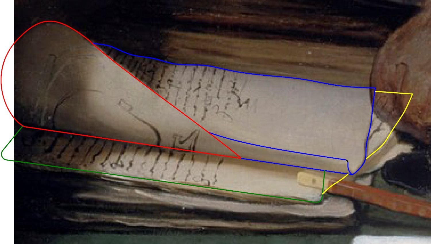
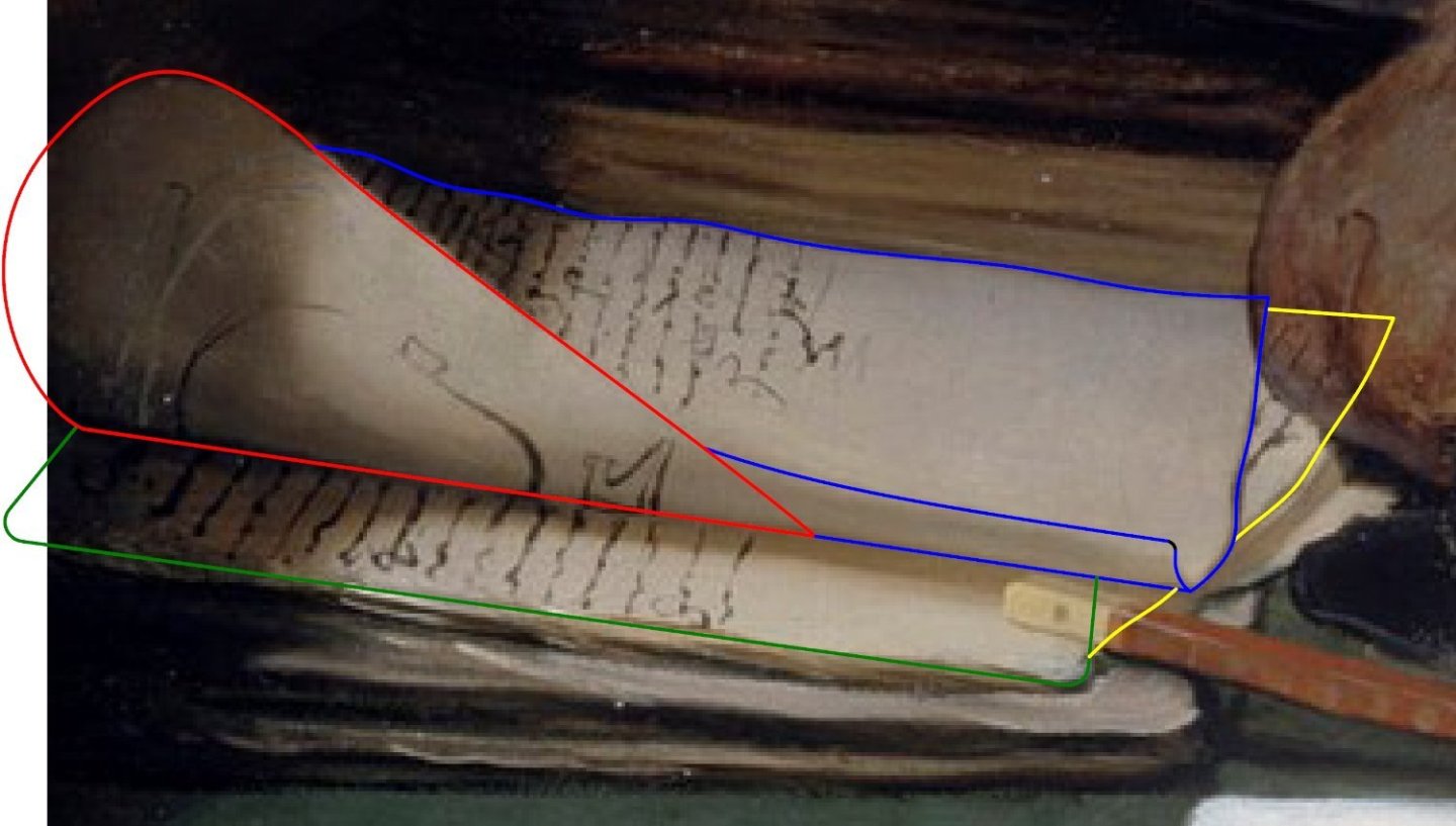
Hello all, Due to the length of this post I cut it in two. Today I will post part 1 of the post. I promise to post part 2 in the very near future. In the last post we saw that the RCE decided to end its report on the authenticity of eighteen drawings in the Scheepvaartmuseum with a teasing question in an 'encore' to their report. So let's start this post with showing the Rembrandt painting the RCE mentioned in the 'encore' of their report '18 Scheepstekeningen van het Scheepvaartmuseum Amsterdam' of Augusts 2022: 'The Shipbuilder and his Wife', 1633: Rembrandt van Rijn, The Shipbuilder and his Wife, Royal Collection Trust, RCIN 405533. To answer the teasing question the RCE put in the 'encore' of its report, "Do we find the first Dutch technical ship drawing ... on a painting?", we have to ask ourselves three questions: 1. When was the painting made? 2. Does the painting show a 'Dutch technical ship drawing'? 3. Are there earlier examples of a 'Dutch technical ship drawing'? To give the short answers to these three questions: 1633, yes, no. An these three short answers would give sufficient information to answer the teasing question of the RCE with: yes, we find the first Dutch technical ship drawing on a painting; on 'The Shipbuilder and his Wife', painted by Rembrandt in 1633. Here is the detail of Rembrandt's painting showing that 'first Dutch technical ship drawing': Detail of Rembrandt's painting 'The Shipbuilder and his Wife'. The sheet op paper underneath the hand of master shipwright of the VOC Jan Rijcksen shows the text "Rembrandt f: 1633", the side view of the assembly of keel, stem- and stern post, the section of the main frame, the front view of the transom assembly, and, at a much larger scale, and rotated, the side view of a stem post. Four questions There are four questions to be asked if we want to give a more complete answer, an answer more in line with the theme of this thread 'Technical drawings & Dutch shell first'. 1. When was the painting made? 2. Who is the sitter in the painting? 3. What is the sitter in the painting doing? 4. What ship building method did the sitter in the painting use? Answer 1 When we want to answer the question when the painting was made, we can of course look at Rembrandt's signature and the date on the painting itself. Rembrandt, according to the signature and date, made the painting in 1633. When we believe Rembrandt made a mistake while signing his painting, we can also have a look at the sitter in the painting. We can be sure Rembrandt made his painting before the sitter, which we will see is Jan Rijcksen, died. Jan Rijcksen was buried in the Oude Kerk, Old Chirch, in Amsterdam on the 31st of January 1637. The Rembrandt Research Project writes about this picture, which it calls A77 (A corpus of Rembrandt paintings, II, 1986, p. 377): "No; A77 is among the best documented of Rembrandt's works." This means there are no doubts about the provenance of the painting. Answer 2 To repeat the question: who is the sitter in the painting? The sitter was identified by Miss Isa van Eeghen, deputy archivist of the Amsterdam municipality archives, in 1970. She published the results of her research in Amstelodamum, 1970, number 6 June/July (in Dutch, my translation): "On the famous painting of Rembrandt, that is known as the master shipbuilder and his wife, the last hands a letter to her husband on which the addressed - several archivists came to that conclusion independently last year - is written clearly: Jan or Jean Heykens. The only person of that name which qualified has been described extensively in previous numbers. But it became more and more unlikely that he was identical to the master shipbuilder in the painting of 1633. He gave 'procuration' in 1629 because he would leave for East India, and in 1634 his wife was described as a widow and his burial registration could not be found. I therefore assume that he died on this voyage. And, the true master shipbuilder emerged in a surprising way. The owner of a portrait of a woman painted by Rembrandt in 1634, whose age emerged after the cleaning of the painting, as the age of her husband on the pendant painting, asked the council archives if their ages coincided with the ages of the husband and wife mentioned as numbers 669a and 669b by Hofstede de Groot. A look at the inventory of the bequest of the son, Cornelis Jansz Rijckx, of 1659, on which Hofstede de Groot based his knowledge, was enough to show that not two paintings were mentioned, but one painting that included both parents, and that this painting was hanging in a house on Rapenburg. I don't know if it was Rapenburg, which is near the shipyards, or the name Jan Rijckx that triggered me to think immediately of the painting on which I worked so long without a gratifying result: the painting of the master shipbuilder. The indexes made it possible to determine in a couple of minutes that Jan Rijcksen, as he signed himself, was indeed a very well off ships carpenter who in 1633 paid the most tax of Rapenburg. The doubts vanished: here he was: the true master shipbuilder!" The sitter is master shipwright of the VOC Jan Rijcksen. Answer 3 What is the sitter in the painting, master shipwright of the VOC Jan Rijcksen, doing? To answer this question let's start with some descriptions of the painting through the ages. Let's start in 1800. 1800 Let's first have a look at the oldest description of Rembrandt's painting I could find. It can be found in an auction catalogue of Van der Schley in Amsterdam of 1800 (in Dutch, my translation): "The image of a master shipbuilder and his wife. Both are painted life size, from above the knees, showing very old people: the man is seated in an arm chair in front of a table, on which lays a piece of paper, with some naval architect sketches, resting with his left hand on the same, he is turned halfway towards his wife, who is behind him, and holds the latch of the door with her left hand, while she presents a letter with the other hand, which he is ready to take, having his compasses hanging over the first finger of that hand: ... : on the table are some books and papers." 1811 And another auction catalogue, this time of Christie in London from 1811, gives the following description of the painting: "The Shipwright is presented in his Closet, a table before him, covered with Sections and Naval Architectural Designs, he is interrupted by his Wife who delivers a letter in haste; the hand upon the Latch of the Door, which gives a spirit and movement to the figures; ...". 1969 But then, in 1969, the catalogue for the exhibition 'Rembrandt 1669/1969 is published. This exhibition includes Rembrandt's 'The Shipbuilder and his Wife' and in the catalogue, written by P.J.J. van Thiel, we find the following description of the painting: "2 THE SHIPBUILDER AND HIS WIFE Canvas 115 x 165 cm. Signed and dated: Rembrandt f. 1633 London Buckingham Palace, Royal Collection In the autumn of 1631 Rembrandt settled in Amsterdam where he received one portrait commission after the other. ... The top sheet, slightly curled, has writing on one side, and, on the reverse, the same kind of technical drawings as on the sheet in front of the man. The second sheet , too, is covered in writing. It is obviously a manuscript. It therefore seems more likely that the man, interrupted in his work, is writing an illustrated paper on ship-building rather than designing a ship, as has alwas been assumed. ... The man's name appears twice in the painting - once as an illegible signature at the bottom of the text on the top sheet of the manuscript, and once on the letter addressed to him and handed to him by his wife. So far, attempts to decipher the address have been fruitless. In older literature the inscription is rendered as: 'den eersamen ende seer ... Joan Vij...', but the first letter of the surname can hardly be read as a V." So, since 1969, 'the man' 'is writing an illustrated paper on ship-building rather than designing a ship, as has always been assumed'. Mind you, this is written one year before 'the man' in the painting is identified as being master shipwright of the VOC Jan Rijcksen by Miss Van Eeghen. Let me try to capture mister Van Thiel's reasoning. The top sheet has writing on one side and technical drawings on the other side. The second sheet is covered in writing. This means this is a manuscript. So Van Thiel's main reasoning is, I think: if a sheet of paper has text on one side and technical drawings on the other side, it is part of a manuscript. And this might be true of course; the technical drawings in the Scheepvaartmuseum for example do not hold large amounts of text. But there's something wrong with Van Thiel's observation; there is no sheet of paper with text on one side and techincal drawings on the other side. Van Thiel's sheet of paper is actually two sheets of paper; one with text, and one with technical drawings. Let me show you what I mean: Van Thiel claims that the blue and red pieces of paper are one piece of paper that has text on one side and technical drawings on the other side. And, although it is clear Van Thiel's manuscript-theory of 1969 is based on a wrong observation, and the sitter in the painting has since been identified as a master shipwright, Van Thiel's manuscript-theory can still be found in today's descriptions of Rembrandt's painting. Let's have a look at some more reliable descriptions of Rembrandt's painting though. 1994 A.J. Hoving, Nicolaes Witsen's Scheeps-Bouw-Konst Open Gestelt, 1994, page 254: "II.455 Rembrandt, Portret van de scheepsbouwer Jan Rijksens en zijn vrouw Griet Jansz. (The Royal Collection 1994, Hare Majesteit Koningin Elizabeth II) Het papier in de hand van de bouwmeester toont de grafische weergave van wat er gewoonlijk in een geschreven bestek te vinden is." My translation: "II.455 Rembrandt, Portrait of shipbuilder Jan Rijksens and his wife Griet Jansz. (The Royal Collection 1994, Her Majesty Queen Elisabeth II) The paper in the hand of the master builder shows the graphic representation of what usually can be found in a written contract." According to Hoving master shipwright Jan Rijcksen is transforming text into technical drawings. 2006 Herman Ketting jr., Fluitschepen voor de VOC, 2006, page 85 (in Dutch, my translation): "The master shipbuilder Jan Rijckesz, receives, while he is transforming his ideas with compass and ruler, a new order or another important massage. Rijckesz. ordered this painting from Rembrandt in the year when his wages were raised. ... He wanted to be portrayed as a proud shipbuilder, who is handed a new order by his wife, while he is working on naval architecture details with compass and ruler." According to Ketting master shipwright Jan Rijcksen is transforming ideas into technical drawings. End of part 1 of this post. To be continued, Jules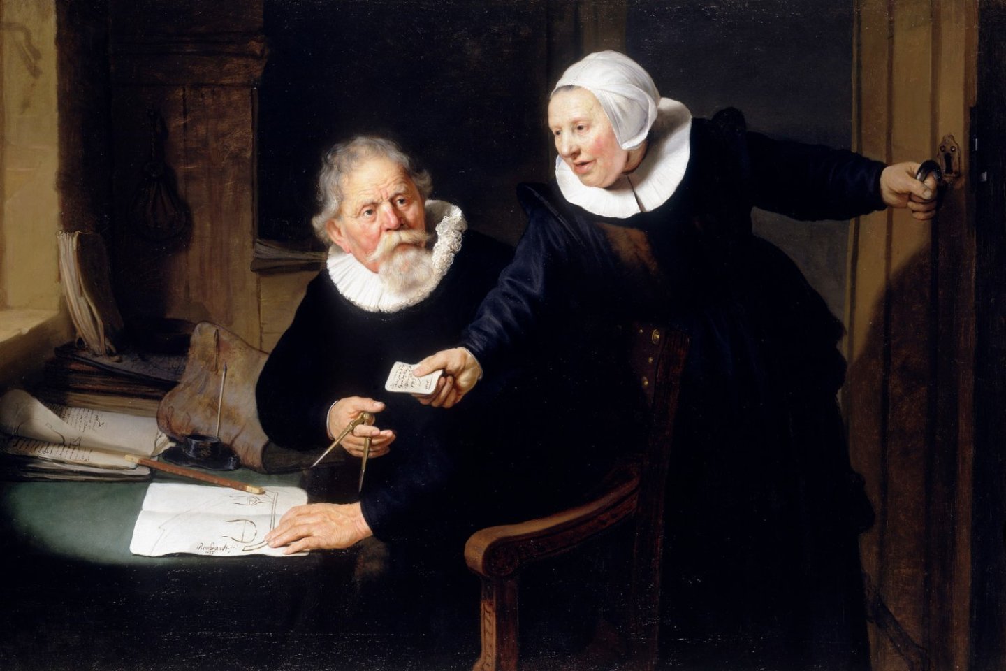
.jpg.f15ab8643faa97d5bcccc1a85b107e71.jpg)
-
Technical drawings & Dutch shell first
Jules van Beek replied to Jules van Beek's topic in Nautical/Naval History
Hello Druxey, About the scales. In the Dutch Republic basically two measuring systems were used in shipbuilding. The first was based on the 'Rijnlandse roede' (the Rhineland rod) with a length of 3767 millimeters; the second was based on the 'Amsterdam roede' (the Amsterdam rod) with a length of 3677 millimeters. The Rhineland rod was divided into 12 feet; the Amsterdam rod was divided into 13 feet. The Rhineland foot was divided into 12 inches; the Amsterdam foot was divided into 11 inches. Luckily the Admiralty and the VOC decided to use the Amsterdam foot as a general, nationwide standard. On the drawings we see a scale based on the Amsterdam foot, which is, as seen, divided into 11 inches. The general principle of the scales is to give a distance of 11 feet, erect one foot perpindicular to the end of the scale of eleven feet, and draw a line from the beginning of the scale to the top of the erected foot. It is now possible to measure all inch sizes in the foot scale. Hello Allan, The interpretation of the technical drawings is totally up to you of course. A lot of Dutch ship modelers use these drawings to build their boats and sloops. So a lot of reconstruction work has already been done , and has been published. I will just mention Kees Dik, Zeven Provincien, 1993, page 165 and 166. Here is a photo of the boat and sloop of the Hohenzollern model that might help. (From: Heinrich Winter, Een hollandse tweedekker uit 1660/1670, 1969, Plaat 40. Boten.) Hello Mark, It's good to see you found this thread, because it was your question of August 16 2021 in the thread 'A critique of the works of NIcolaes Witsen' that sparked this thread into life. You are talking about 'an article in the Nautical Reasearch Journal' written by 'a well-known author some years ago'. And it is this article that made the Scheepvaartmuseum order the research of the RCE to determine the authenticity of their eighteen drawings. Let me explain. A couple of years ago I had a conversation with the late Frank Fox when he asked me which sources I used for my work. I gave him a list and on this list were, of course, the technical drawings in the Scheepvaartmuseum. Frank then said to me that an article was published in NRJ that explained that all these drawings are fakes, and that I probably should not use them for my research. I was absolutely amazed that a person like Frank Fox, and a lot of his colleagues as it turned out, took this article seriously. So I sent Frank my rebuttal, as you call it, and decided to take up contact with the Scheepvaartmuseum. I informed the Scheepvaartmuseum about the claims that their technical drawings were fakes, and asked them why they did not respond to these claims. The point is, they were not aware of these claims. After some time the Scheepvaartmuseum decided that the best way forward was to have their technical drawings tested, which resulted in the report of the RCE. Thanks for showing the rowing lay out. Hello Jaager, Thank you for your explanation. Kind regards, Jules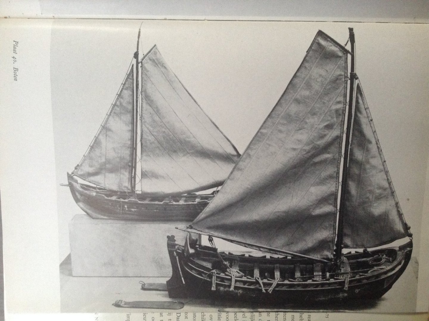
-
Technical drawings & Dutch shell first
Jules van Beek replied to Jules van Beek's topic in Nautical/Naval History
Hello all, As promised in the last post I will give some general information about the technical drawings we have found in the Scheepvaartmuseum in Amsterdam until now. Authenticity of the technical drawings in the Scheepvaartmuseum Three of the technical drawings we found in the Scheepvaartmuseum in Amsterdam in the previous posts were selected to be tested for their authenticity by that same Scheepvaartmuseum in Amsterdam in 2021. These three technical drawings are: States yacht, Jacobus Storck, 2015.4375. States yacht, Jacobus Storck, 2015.4376. Sloop of 24 feet, A.0145(278)02. The Scheepvaartmuseum did not only decide to test these three technical drawings, but also another fifteen drawings that they keep in their collection. This group of fifteen drawings included eleven technical drawings, two artistic drawings made by J. Storck, and two artistic drawings made by Abraham Storck. The eleven technical drawings from this group of fifteen were: Warship, Johannis Sturckenburgh, 2015.4372. Warship, Johannis Sturckenburgh, A.0149(0855). Pinas, A.0149(0861). Pinas, A.0149(0856). Pinas, A.0149(0857). Pinas, A.0149(0863). Pinas, A.0149(0858). Pinas, A.0149(0859). Pinas, A.0149(0860). Pinas, A.0149(0862). Sloop of 28 feet, A.0149(0871). Here it is: Scheepvaartmuseum, Amsterdam. A.0149(0871). Technical drawing of a sloop of 28 feet. 18,5 x 30 cm. The drawing's texts read (my translation): "a boat from behind", "a boat from the front", "a boat from the side", "long over all 28 feet". We also find the term "water strock", "water level", in split writing twice. The Scheepvaartmuseum had their eighteen selected drawings tested by the 'Rijksdienst voor Cultureel Erfgoed', the 'Cultural Heritage Agency' of the Netherlands. The 'Rijksdienst voor Cultureel Erfgoed (RCE) gathered the findings of their research in a report marked ' Research report 2021-089', dated the report '25-8-2022', and called it: "18 Scheepstekeningen van het Scheepvaartmuseum Amsterdam, Materiaal-Technisch onderzoek". Which I would translate with: "18 Ship drawings of the Scheepvaartmuseum Amsterdam, Material-Technical research". The RCE prefers the following reference to their report: Reisland B., Porck, H., Joosten I., Proano Gaibor, A., Pause R., 2022 18 Scheepstekeningen van het Scheepvaartmuseum Amsterdam - Materiaaltechnisch onderzoek, RCE projectnummer 2021-089, Amsterdam, Rijksdienst voor het Culturele Erfgoed, Rijkserfgoedlaboratorium. The report the RCE produced for the Scheepvaartmuseum was an extensive report. The main report counts 40 pages, attachment 1 'Photo documentation' counts 56 pages, attachment 2 'Technical imaging' counts 22 pages, attachment 3 'SEM-EDX' counts 70 pages, and attachment 4 'UHPLC-PDA-HRM' counts 34 pages; 222 pages in total. The RCE chose seven categories of research to determine if the eighteen drawings were authentic: paper historical evidence, visual analysis, VSC, sample taking, SEM-EDX, HP-LC, and Raman. The research methods used by the RCE included: paper history research, visual analysis and technical imaging (VSC 8000), taking micro samples of the inks (MOMS), analysis of the micro samples with electron microscopy (SEM-EDX), analysis of the micro samples by liquid chromatography (UHPLC-PDA-HRMS/AFFA), microscopic research (Hirox 3D), and spectroscopy (mu-RS). All eighteen drawings were chosen to undergo the first two categories of research: paper historical evidence and visual analysis. Some of the eighteen drawings were chosen to undergo extra categories of research, but only three of the eighteen drawings were chosen to undergo all seven categories of research. Two of 'our' three technical drawings were part of this select group of three: States yacht, Jacobus Storck, 2015.4376 and Sloop of 24 feet A.0145(278)02. The third technical drawing of this select group was: Pinas, A.0149(0861). Here it is: Scheepvaartmuseum, Amsterdam. A.0149(0861). Technical drawing of a pinas of 90 feet. 30,5 x 40 cm. Though the report of the RCE is very extensive in its description of all the tests involved in its research, I will not get into how all these tests were executed. If there are any questions, just ask; I will do my best to give an answer. Instead of talking about the tests I will jump to the conclusions of the report. These conclusions can be found in three locations of the report of the RCE: in the 'Samenvatting' (Summary), in the Extended summary (in English), and in the 'Conclusie' (Conclusion). Conclusion 1 From the 'Samenvatting' (my translation): "... This research has given no cause to doubt the authenticity of the drawings. The study of the present watermarks and other characteristics of the way the paper is made, and the research into the drawing materials and -techniques give results that do not conflict with a seventeenth century provenance. Some drawings that were dated in or before 1650 by the Scheepvaartmuseum contain watermarks in the paper that give reason to date them at a later production date, in the second half of the seventeenth century." Conclusion 2 From the 'Extended summary': "... The results of the material-technical investigations give no reason to doubt the authenticity of the drawings. ...". Conclusion 3 From the 'Conclusie' (my translation): "The reasearch on the paper and the drawing materials and -techniques of the eighteen drawings of the Scheepvaartmuseum produces an image that fits well with the seventeenth century methods and techniques of production and use of writing- and/or drawing paper. Also the clues for the foreign provenance of the paper are in accordance with the seventeenth century in the Netherlands. ... ... that the drawings signed with Jacobus Storck (2015.4375 and 2015.4376), ..., are not real but fake, is not supported by our research. ...". I think we can conclude, based on the conclusions of the RCE, that the eighteen drawings of the Scheepvaartmuseum are authentic seventeenth century drawings. And, since this group of eighteen drawings contains the three technical drawings we found earlier, the two drawings of a states yacht made by Jacobus Storck and the drawing of a sloop of 24 feet, I think we can conclude that these three technical drawings are also authentic seventeenth century drawings. Thanks to the initiative of the Scheepvaartmuseum these eighteen drawings can now proudly carry the Seal of Authenticity of the RCE. The RCE and Rembrandt The RCE, unexpectly, to me at least, concludes its very serious report with a teasing question in an 'encore': "Vinden we de eerste Nederlandse technische scheepstekening ... op een schilderij?" Which I would translate with: "Do we find the first Dutch technical ship drawing ... on a painting?" After posing this teasing question the RCE gives a reproduction of a well known painting of Rembrandt of 1633, and gives that reproduction the following caption: "Rembrandt van Rijn, De scheepsbouwer en zijn vrouw: Jan Rijcksen (1560-1637) en zijn vrouw, Griet Jans, 1633, Picture Gallery, Buckingham Palace." This Rembrandt painting is usually referred to in English as 'The shipbuilder and his Wife'; more about this painting in the next post. To be continued, Jules.jpg.a7ac7afd7ab022928057b380259e31ab.jpg)
.jpg.c0c6e6454c7b3abd1d3cd8f28a259dd0.jpg)
-
Technical drawings & Dutch shell first
Jules van Beek replied to Jules van Beek's topic in Nautical/Naval History
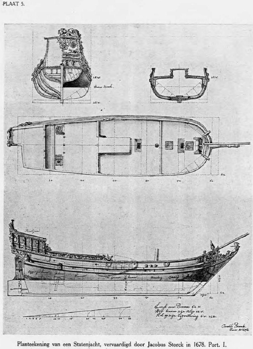
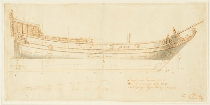
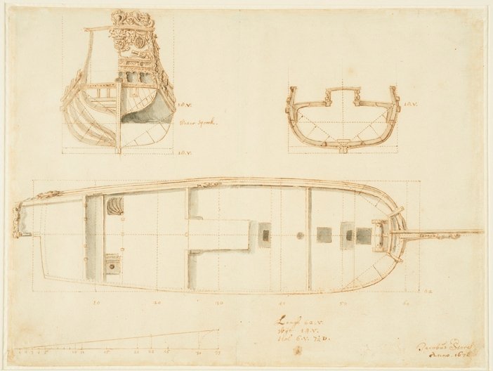
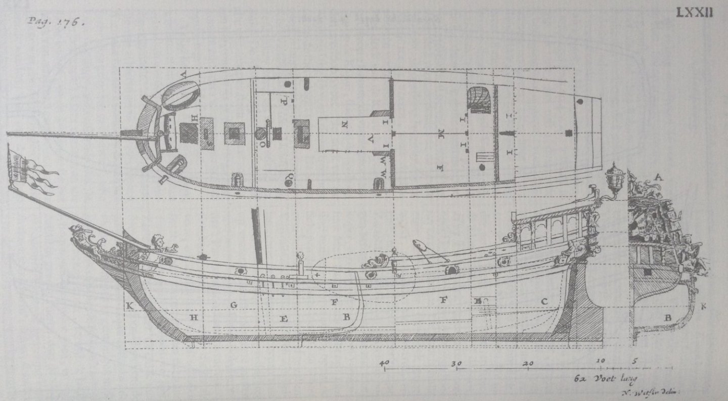
Hello all, In the last post we found two original drawings of a wideship that are kept in the Scheepvaartmuseum in Amsterdam which were used by Nicolaes Cornelisz Witsen to write his books of 1671 and 1690. To find more technical drawings in the possession of the Scheepvaartmuseum which were used by Nicolaes Cornelisz Witsen, let's first have a look at the 'Desciptive catalogue of ship models and naval architecture drawings, 1600-1900' written by Voorbeijtel Cannenburg in 1943 again. Voorbeijtel Cannenburg, 1943 On page 100 of the 'Desciptive catalogue' of 1943, right above the entries for the wideship and the sloops we have found in the last post, we find the following entry: "Statenjacht. Lang 62 vt, wijd 18 vt, hol 6 vt 7 1/2 dm. Spantenteekening, zij- en bovenaanzicht, doorsnede grootspqnt. Gemerkt: Jacobus Storck, 1678. Plaat 5." My translation: "States yacht. Long 62 ft, wide 18 ft, depth 6 ft 7 1/2 in. Frame drawing, side- and top view, section main frame. Marked: Jacobus Storck, 1678. Plate 5." The 'Plate 5' Voorbeijtel Cannenburg mentions, is placed between the pages 16 and 17 of his 'Descriptive catalogue'. Here it is: Voorbeijtel Cannenburg, Beschrijvende catalogus der scheepsmodellen en scheepsbouwkundige teekeningen, 1600-1900, 1943, Plaat 5. "Planteekening van een Statenjacht, vervaardigd door Jacobus Storck in 1678. Port. I." In the caption of the plate Voorbeijtel Cannenburg gives the drawing the title (my translation): "Plan drawing of a States yacht, produced by Jacobus Storck in 1678." And indeed plate 5 of Voorbeijtel Cannenburg seems to show a very clearly written '1678'. The drawings in the Scheepvaartmuseum Plate 5 of Voorbeijtel Cannenburg's 'Descriptive catalogue' actually shows a combination of two seperate technical drawings of the states yacht. The first drawing shows the side view of the states yacht, the second drawing shows the frame drawing, the section of the main frame and the top view of the states yacht. It turns out that by combining these two drawings to make one plate, some information on the second drawing was lost. We therefore better have a look at the two seperate drawings in the Scheepvaartmuseum. The first technical drawing of the states yacht was given number 2015.4375 by the Scheepvaartmuseum. Here it is: Scheepvaartmuseum, Amsterdam. 2015.4375. Side view of a states yacht. 19,6 x 39,9 cm. This drawing is signed in the bottom right corner: "Jacobus Storck. Fecit A: 16??". The last two digits can no longer be read. The second technical drawing of the states yacht was given number 2015.4376 by the Scheepvaartmuseum. Here it is: Scheepvaartmuseum, Amsterdam. 2015.4376. Views and sections of a states yacht. 29,3 x 30,7 cm. We can tell from the complete technical drawing 2015.4376 that Voorbeijtel Cannenburg simply cut the lower part of this drawing to incorporate it in his plate 5. In his plate 5 the scale bar, the information about the length, width and depth of the yacht, and the title is missing. The title, in the bottom right corner of the drawing, reads: "Jacobus Storck Anno. 167?". The last digit can no longer be read. It is clear that the dates on these two technical drawings of the states yacht by Jacobus Storck can no longer be read. We have seen that Voorbeijtel Cannenburg in 1943 gives the dates on the drawings as 1678, but, when we check some older sources, we can find the following on page 92 of 'Nederlandse Jachten' of 1926 (reprint 1978) by G.C.E. Crone: "Naast Witsens afbeeldingen bezit het Nederl. Hist. Scheepvaart Museum de fraaie origineele teekening van een langsscheepsche sectie en dekplan door Jacobus Storck, gedateerd 1670." My translation: "Next to Witsen's images, the Dutch Historic Scheepvaart Museum possesses the beautiful original drawing of a longitudinal section and deck plan by Jacobus Storck, dated 1670." A Swedish Royal Yacht of 62 feet, Witsen 1671 Nicolaes Cornelisz Witsen writes the following about a states yacht on page 176, I of his 'Aeloude en Hedendaegsche Scheeps-Bouw en Bestier' of 1671 (my translation): "Follows the Swedish Royal Yacht, which dimensions can be drawn from the base plan, that's why I will not give them. A is its transom, as seen from behind; sinks in the water to K, at B see the Yacht cut, or its opening, well understood that the extreme shows the rising of the flat for this Yacht, and the inner one shows the flat of a yacht of the same size, which would be used in our land; because this Yacht will sail deep waters, it is made a little sharper, and will therefore go deeper than the plumper one; ... the floor is wider than normal in these Yachts, bacuase the same comes in the widest of the Ship, because the Yacht being sharper will go deeper, and must therefore carry much ballast, on which the floor or bottom will be laid; ...". The 'base plan' Witsen mentions for this 'Swedish Royal Yacht' is plate LXII which can be found between the pages 176 and 177 of his book of 1671. Here it is: A Swedish Royal Yacht of 62 feet, Witsen 1690 Nicolaes Cornelisz Witsen gives the same description of the Swedish Royal Yacht in his 'Architectura Navalis et Regimen Nauticum' of 1690 as he gave in his book of 1671, but he adds an important remark (my translation): "This Yacht was built by Jan Ysbrantsz. Hoogzaat, a Master, very famous in the art of building ships which sail the inland waters." Nicolaes Cornelis Witsen did not order a new plate of the yacht for his book of 1690; he used the same plate of the Swedish Royal Yacht in his book of 1690 as he had used in his book of 1671. I will therefore not show that plate here again. It is clear from the descriptions and drawings of the Swedish Royal Yacht in Nicolaes Cornelisz Witsen's books of 1671 and 1690, that he actually gives two drawings of a states yacht: one for a yacht that is suited for the deep Swedish waters, and one for a yacht that is suited for the shallow Dutch waters. This extra information is missing in Jacobus Storck's drawing. Storck's drawings only shows a states yacht that is suited for the shallow Dutch waters. We can only guess how Nicolaes Witsen acquired the knowledge to give these variations, but it looks like he had a talk with the builder of the Swedish Royal Yacht: Jan Ysbrantsz Hoogzaat. Dates The above leads to an interesting question: which one was first; the two technical drawings of the states yacht made by Jacobus Storck, or plate LXXII of Nicolaes Witsen of 1671? Did Nicolaes Witsen use the drawings of Jacobus Storck to make the plate for his book of 1671, or did Jacobus Storck make his two technical drawings after the publication of Witsen's book of 1671? Research is ongoing. The two technical drawings of a states yacht by Jacobus Storck are the last examples of original technical drawings I could find in the Scheepvaartmuseum that have a relation with the books of 1671 and 1690 of Nicolaes Cornelisz Witsen. In the next post I will give some general information about the drawings we have found in the Scheepvaartmuseum until now. Until then. To be continued, Jules
-
Technical drawings & Dutch shell first
Jules van Beek replied to Jules van Beek's topic in Nautical/Naval History
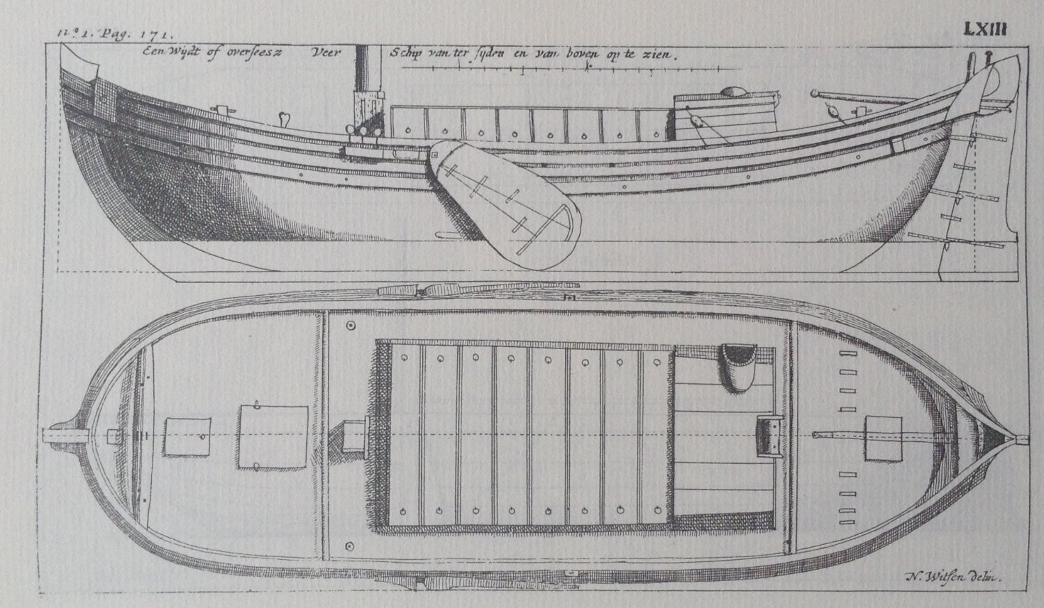
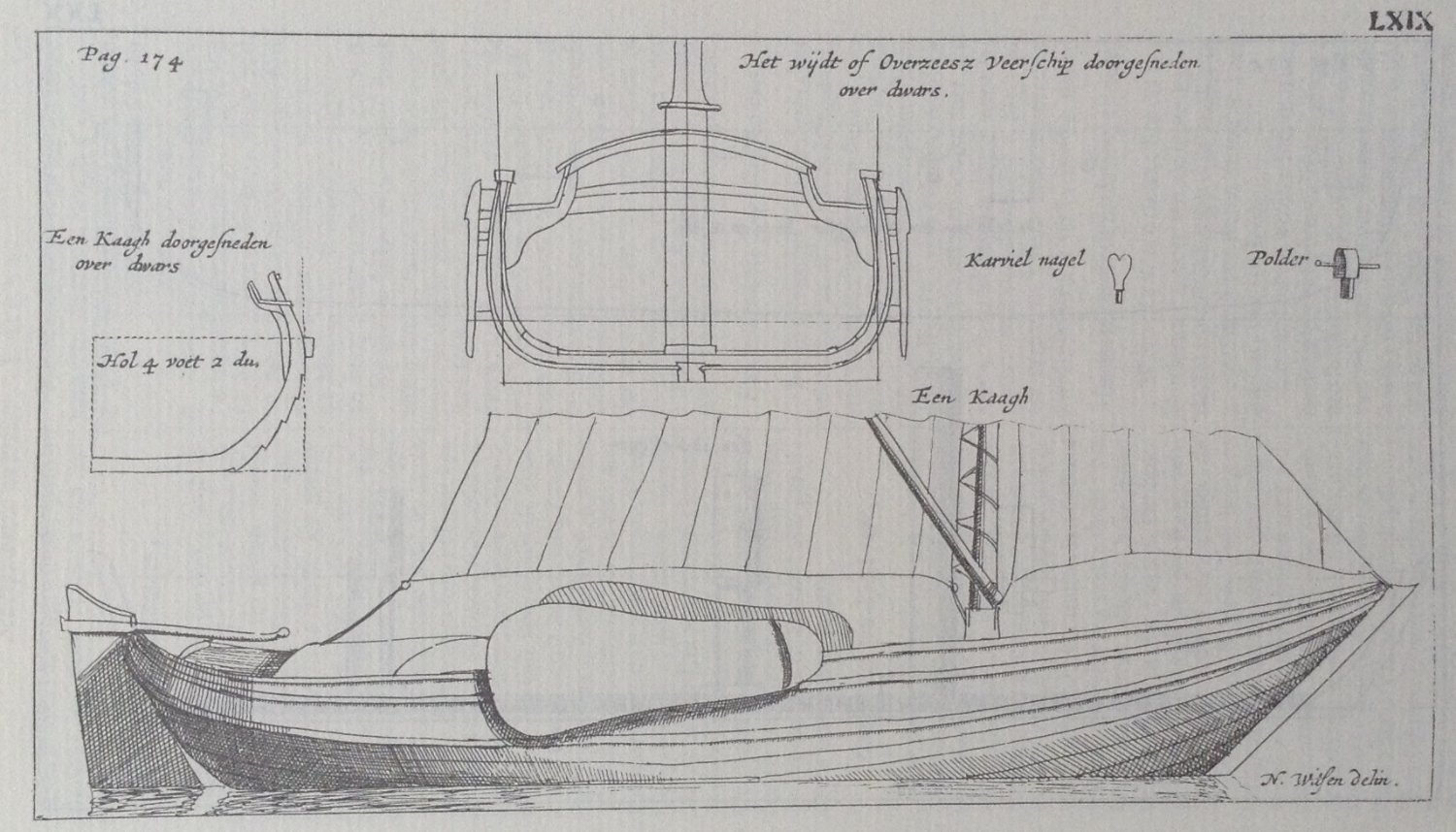
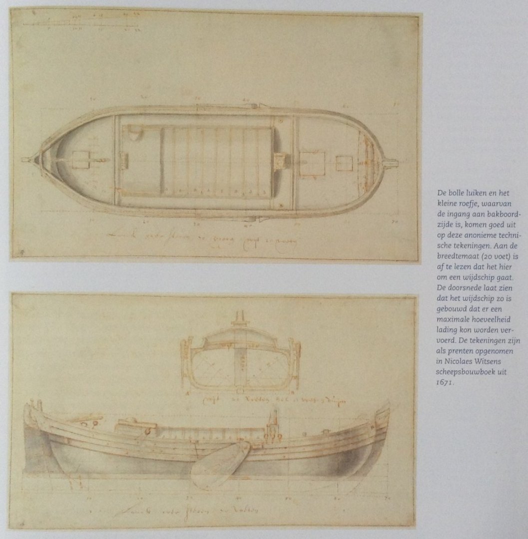
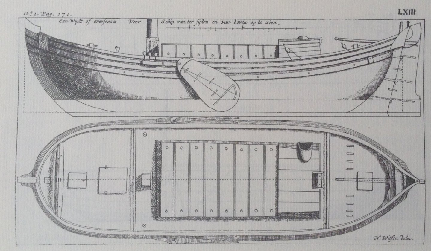
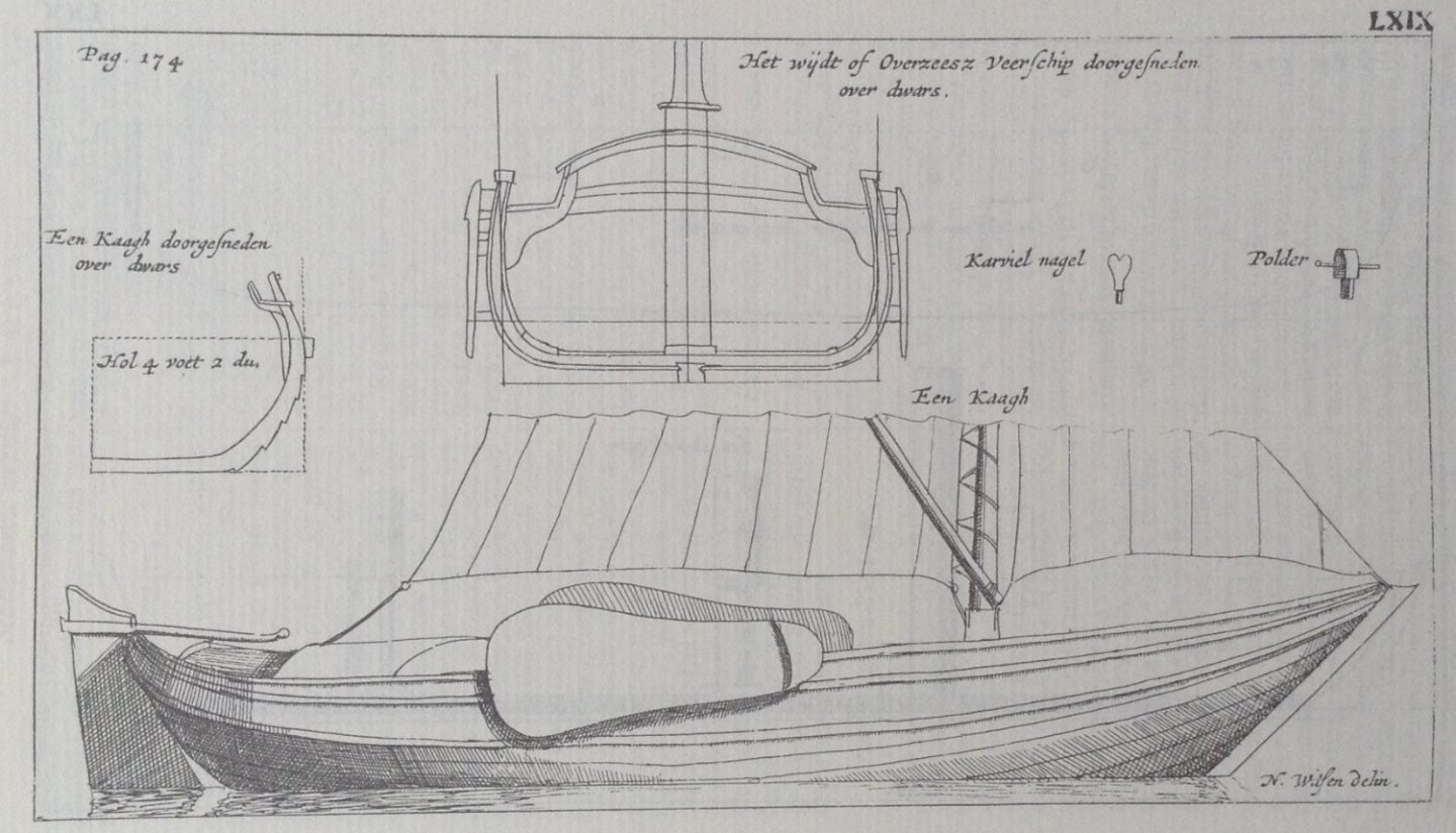
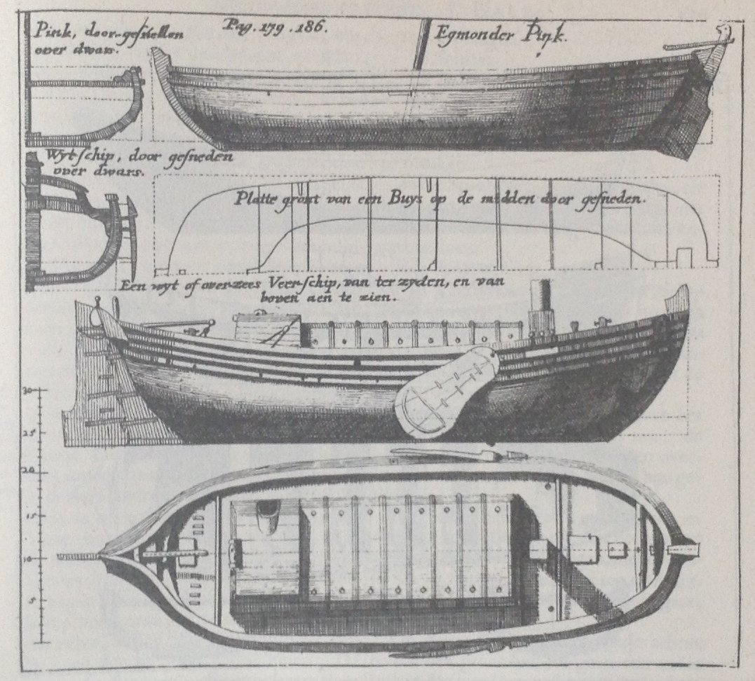
Hello all, In my last post of the 10th of June we saw that the five technical drawings of a sloop of 24 feet, which were made by Cornelis Jansz Witsen, and of which Nicolaes Cornelisz Witsen published the copies in his 'Aeloude en Hedendaegsche Scheeps-Bouw en Bestier' of 1671 and in his 'Architectura Navalis' of 1690, are kept in the Scheepvaartmuseum in Amsterdam. I think it might be of interest to know if there are more original technical drawings kept in the Scheepvaartmuseum in Amsterdam that were used by Nicolaes Cornelisz Witsen to write his books of 1671 and 1690. Let's start our search in 1943. Voorbeijtel Canneburg, 1943 Former naval officer Willem Voorbeijtel Cannenburg (1883-1978) was the director of the Scheepvaartmuseum in Amsterdam in 1943 when he wrote the 'Beschrijvende catalogus der scheepsmodellen en scheepsbouwkundige teekeningen, 1600-1900', the 'Descriptive catalogue of ship models and naval architecture drawings, 1600-1900'. In this 'Descriptive catalogue' Voorbeijtel Cannenburg mentions several technical drawings of the seventeenth century which are in the possession of 'his' Scheepvaartmuseum. On page 100 we can find listed (my translation): "Wideship 1). Long 70 ft, wide 20 ft. Side- and top view, section main frame. Sloop. Long 28 ft. Side-, aft-, and top view, vertical length section, section main frame. Sloop. Long 28 ft. Side- and top view, section main frame. Sloop. Long 24 ft. Side- and top view, vertical length section, two vertical cross sections." The 1) behind the 'Wideship' relates to a footnote on the bottom of that same page 100. In that footnote Voorbeijtel Cannenburg says: "1) Enkele der teekeningen van het wijdtschip en de chaloupen zijn gemerkt 'N. Witsen' en blijkbaar bestemd geweest voor diens groote werk over den scheepsbouw." My translation: "1) Some of the drawings of the wideship and the sloops are marked 'N. Witsen', and were probably destined to be used for his great work about shipbuilding." With the 'great work about shipbuilding' by 'N. Witsen' Voorbeijtel Cannenburg undoubtedly means Nicolaes Cornelisz Witsen's 'Aeloude en Hedendaegsche Scheeps-Bouw en Bestier' of 1671. The original drawings of the wideship With his listing 'Wideship' Voorbeijtel Cannenburg is actually not referring to one, but to two drawings which are in the possession of the Scheepvaartmuseum. These two drawings were later given the numbers A.0149(0869) and A.0149(0870) by the Scheepvaartmuseum. Here is one of them: A.0149(0870). Technical drawing of a wideship. Scheepvaartmuseum, Amsterdam. 15,9 x 27,6 cm. Both technical drawings of the wideship were used to illustrate a publication of the Scheepvaartmuseum of 2005: 'Schepen van de Gouden Eeuw', 'Ships of the Golden Century'. We can find them on page 13 of that publication. Here is how the drawings are presented in that publication: The two technical drawings of the wideship in 'Schepen van de Gouden Eeuw', 2005, page 13. The caption, written by Drs. Ernst van Keulen, reads (my translation): "The convex hatches and the small deckhouse, of which the entrance is on the port side, are well depicted on this anonymous technical drawing. We can tell from the width (20 feet) that this is a wideship. The section shows that the wideship is built in such a way that a maximum of cargo can be transported. The drawings are included as prints in Nicolaes Witsen's book on shipbuilding of 1671." Wideship, Witsen 1671 Both the drawings of the wideship in the Scheepvaartmuseum were used by Nicolaes Cornelisz Witsen to make a plate which is incorporated in his book of 1671. The plate is named 'LXIII' and is bound between the pages 170 and 171. Here it is: The section of the wideship is placed on another plate, named 'LXIX', which is bound between the pages 174 and 175 of Witsen's book of 1671. Here is that plate: The specifications of the wideship can be found on page 171, I. My translation: "The Wide-ship Is long 70 feet, wide 20 feet, deep 8 feet 2 inches. The stern post high 12 feet 6 inches, wide above 1 1/2 feet, rakes 3 feet: the stem post high 17 feet 5 inches, rakes 7 feet 5 inches, wide above 2 1/2 feet: ... The rudder which is shown hanging more or less, should be straight up and down, it is hanging, to say it in seaman's terms, too much under its ****." Wideship, Witsen 1690 A new plate of the wideship is incorporated in Witsen's book of 1690. This plate is bound between the pages 178 and 179. Here is that plate: The specifications of the wideship can be found on page 189, II: "Maat van een Wydt-schip." As Drs. Ernst van Keulen already mentions in 2005, the author of the two original technical drawings of the wideship is unknown. But, since these two technical drawings were used to make the plates in Nicolaes Cornelisz Witsen's book of 1671, they must have been made before 1671. And, as we've seen in a former post, Nicolaes Cornelisz Witsen mentions in his foreword of that same book of 1671: "Never would I have dared to take up the Work of the new Ship-Building, if not had dropped into my hands, some ground-rules and drawings, formerly designed by my late father Cornelis Witsen." Taking these two facts into account, it maybe is justified to conclude that the two original technical drawings of the wideship which are kept in the Scheepvaartmuseum are from the hand of Cornelis Jansz Witsen. To be continued, Jules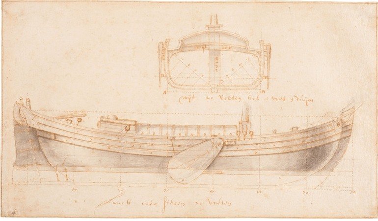
-
Technical drawings & Dutch shell first
Jules van Beek replied to Jules van Beek's topic in Nautical/Naval History
Hello all, Now that we have determined that the technical drawings of the boat and the sloop in Nicolaes Cornelisz Witsen's 'Aeloude en Hedendaegsche Scheeps-Bouw en Bestier' of 1671, and 'Architectura Navalis et Regimen Nauticum' of 1690, books describing the Dutch shell first shipbuilding method, are from the hand of Cornelis Jansz Witsen, this may be the right time to reflect on what we are actually looking at when we look at the plates with the technical drawings in Witsen's books. I daily life I am using facsimile reproductions of Nicolaes Witsen's books of 1671 and 1690. I can maybe get closer to the real books by using the versions of these books on the internet, but that hardly helps. What we are looking at are reproductions of photos of the original books, either on paper, either on screen. But even when we look at the plates with the technical drawings of the boat and sloop in the original books of 1671 and 1690, we are only looking at prints made with the copper plates Nicoales Witsen made; Nicolaes made a copy of his father's drawings on a copper plate, and the prints made with these copper plates were used in his books. And it is Nicolaes Witsen himself who says in the foreword of his book of 1671 (my translation): "The drawing-work is not very well finished, because our goal is not to present costly copper prints, but to only depict the appearance of things so it can be printed, which can be done with bad plates, and with costly plates." So, even when we look at the plates of the drawings of the boat and sloop in an original print of one of the two books of Nicolaes Cornelisz Witsen, we do not look at the original drawings of the boat and sloop that his father Cornelis Jansz Witsen made. For the sake of better understanding the use of technical drawings when working according to the Dutch shell first shipbuilding method, it is therefore important to find the original technical drawings that were made by Cornelis Jansz Witsen. To say it differently, it is important to find the original drawings that his son Nicolaes Cornelisz Witsen used to make his copper plates to illustrate his books of 1671 and 1690. Luckily we can still find some of the original technical drawings Cornelis Jansz Witsen made in the Scheepvaartmuseum in Amsterdam. Technical drawings in the Scheepvaartmuseum in Amsterdam The Scheepvaartmuseum in Amsterdam holds a collection of technical drawings of sloops from the seventeenth century. Here is one of them, a technical drawing of a sloop of 24 feet, dated 1650 by the Scheepvaartmuseum, which holds the inventory number A.0145(278)01: A.0145(278)01. Technical drawing of a sloop of 24 feet. Scheepvaartmuseum, Amsterdam. 17,6 x 29,4 cm. The three views on this drawing of a sloop of 24 feet from the Scheepvaartmuseum strongly resemble the three views we found on the plates of the sloop of 24 feet in Nicolaes Cornelisz Witsen's book of 1671. And here is another technical drawing of a sloop of 24 feet from the Scheepvaartmuseum, A.1045(278)02: A.1045(278)02. Technical drawing of a sloop of 24 feet. Scheepvaartmuseum, Amsterdam. 16,6 x 27,6 cm. The top view on this drawing of a sloop of 24 feet in the Scheepvaartmuseum strongly resembles the top view on the plates of the sloop of 24 feet in Nicolaes Witsen's book of 1671. And here is yet another drawing of a sloop of 24 feet from the Scheepvaartmuseum, A.1045(278)03: A.1045(278)03. Technical drawing of a sloop of 24 feet. Scheepvaartmuseum, Amsterdam. 18 x 27,3 cm. The side view on this drawing of a sloop of 24 feet in the Scheepvaartmuseum strongly resembles the side view on the plates of the sloop of 24 feet in Nicolaes Cornelisz Witsen's book of 1671. It is obvious, to me, that these three technical drawings of a sloop of 24 feet from the Scheepvaartmuseum in Amsterdam are the original technical drawings Cornelis Jansz Witsen made, that these drawings ended up in the hands of his son Nicolaes Cornelis Witsen by inheritance in 1669, that Nicolaes Cornelisz Witsen used these three drawings to make the copper plates to illustrate his book of 1671, and that these three drawings eventually found their way to the Scheepvaartmuseum in Amsterdam. To be continued, after my holidays, Jules

-
Technical drawings & Dutch shell first
Jules van Beek replied to Jules van Beek's topic in Nautical/Naval History
Hello all, In post number 4 we found the second location of the 'ground-rules and Drawings designed by Cornelis Jansz Witsen in the two books about Dutch shell first shipbuilding written by his son Nicolaes Cornelisz Witsen: the specifications and the accompanying technical drawing of a sloop of 24 feet. Let's move on to the third location. Tutor Jan Dircksz Grebber From a passage in Nicolaes Cornelisz Witsen's 'Architectura Navalis et Regimen Nauticum' from 1690, we can conclude that his father Cornelis Jansz Witsen was educated in shipbuilding by a master shipwright. The passage can be found on page 139, II: "Volght een generale Certer, of liever Tafel, waar uit men zien kan alle grootheden van de voornaamste Scheeps deelen, die men in het bouwen noodighst heef te weten, en zulks van Scheepen lang over steven van 60 tot 200 voeten, voor omtrent zes-en-dertig of veertigh jaaren evenredigh by een gestelt door wylen de vermaarde Scheeps-bouwmeester Jan Dirksz. Grebber, die wylen myn Vaders Meester in deeze konst was." My translation: "Follows a general Charter, or rather Table, from which one can see all sizes of the main ship-parts, which are known to be the most necessary for the build, and such for ships long over all from 60 to 200 feet, for about 36 or 40 years proportionally placed together, by the late famous Master shipwright Jan Dirksz. Grebber, who was the Tutor of my late father in this art." This passage can already be found in Nicolaes Cornelisz Witsen's 'Aeloude en Hedendaegsche Scheeps-Bouw en Bestier' of 1671, but much shorter, on page 113, II: "Volgt een generaele Certer, of liever Taefel, waer uit men zien kan alle grootheden van de voornaemste scheeps-deelen, die men in het bouwen noodigst heeft te weten, en zulks van schepen lang over steven van 60 voeten af, tot 200 voeten toe, proportioneel by een gestelt, by wijlen de vermaerde Scheepsbouw-meester, Jan Dirrikze Grebber." My translation: "Follows a general Charter, or rather Table, from which one can see all sizes of the main ship-parts, which are known to be the most necessary for the build, and such for ships long over all from 60 to 200 feet, proportionally placed together, by the late famous Master shipwright Jan Dirrikze Grebber." So in his book of 1671 NIcolaes Witsen does not mention the age of the 'Charter' of 'Table', and, more importantly, does not mention that master shipwright Jan Dircksz Grebber was the tutor of his father. Luckily he corrects these omissions in his book of 1690. The table of Jan Dircksz Grebber According to the introduction of the 'Table' in Witsen's book of 1690, the 'Table' must have been composed by master shipwright Jan Dircksz Grebber in 1650 or 1654. The 'Table' of Jan Dircksz Grebber can be found on page 114 of Nicolaes Cornelisz Witsen's book of 1671 and on page 14 of his book of 1690. Here is Jan Dircksz Grebber's 'Table' as reproduced in Nicolaes Witsen's book of 1671: Master shipwright Jan Dircksz Grebber's 'Table' contains information about the main dimensions of the ship and of dimensions of important ship parts related to the length of the ship. We find dimensions for the width of the ship, the depth of the ship, the width of the flat of the ship, the rise of the flat of the ship, the width at the bilge of the ship, the depth at the bilge of the ship, the height of the stem post, the rake of the stem post, the height of the stern post, the rake of the stern post, the length of the transom, the thickness, width and curve of the transom, the rise of the wales fore, the rise of the wales aft, the height of the second deck, etc. From this 'Table' we can also learn that the width of the ship was equal to one fourth of the length of the ship, that the depth of the ship was equal to one tenth of the length of the ship, that the width of the flat of the ship was equal to one sixth of the length of the ship, etc. Since master shipwright Jan Dircksz Grebber was the tutor of Cornelis Jansz Witsen, it seems to be a safe assumption that Cornelis Jansz Witsen was in the possession of the 'Table' that was created by his tutor master shipwright Jan Dircksz Grebber, and that his son Nicolaes Cornelisz Witsen came into the possession of Jan Dircksz Grebber's 'Table' after his father died in 1669. Cornelis van Yk published Jan Dircksz Grebber's 'Table', which he had found in Nicolaes Witsen's work, on page 124 and 125 of his 'De Nederlandsche Scheeps-Bouw-Konst Open Gestelt' of 1697, and Nicolas Aubin published Jan Dircksz Grebber's 'Table', which he had also found in Nicolaes Witsen's work, on page 265 of his 'Dictionaire de Marine' of 1702. Cornelis van Yk gave the 'Table' the following title (my translation): "Table of the principal Ship-Parts, composed by Jan Dirksz Grebber, famous Master-Shipwright of Amsterdam, found in the Book of the noble Gentleman Nicolaus Witsen." This concludes the description of the third, and last, location of the 'ground-rules and drawings' designed by Cornelis Jansz Witsen in the two books about Dutch shell first shipbuilding of his son Nicolaes Cornelisz Witsen. I think we can now draw the conclusion that Cornelis Jansz Witsen was able to make a design for a boat of 32 feet, that he was able to make a design for a sloop of 24 feet, and that he was able to make these designs, including the accompanying technical drawings, because he had a famous master shipwright as a tutor who showed him how to do that: Jan Dircksz Grebber. To be continued, Jules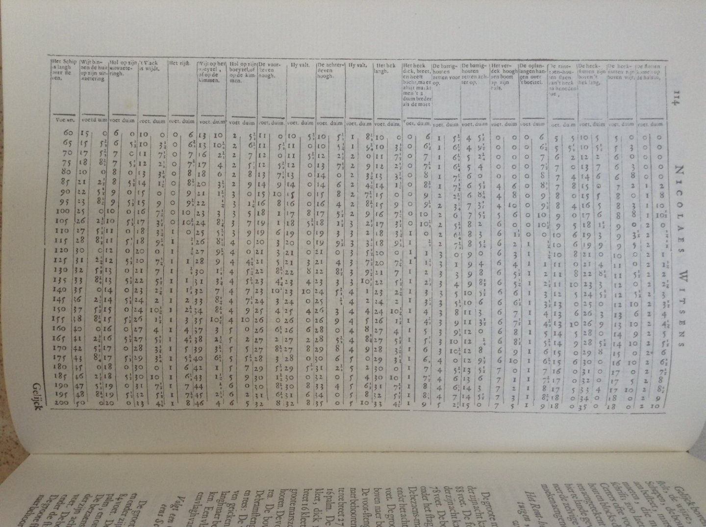
-
Technical drawings & Dutch shell first
Jules van Beek replied to Jules van Beek's topic in Nautical/Naval History
Hello Jaager, Thank you for sharing your reflections on Nicolaes Witsen and his books. I never heard anyone using the term 'dissertations' for his books. Thank you for that idea. I think you are right in emphasizing the problems with the scale behaviour of materials. Replicating the shape of a life size hull of a ship on scale, just by replicating the building method used to build that life size hull on scale, to me, seems illusory. But, on the other hand, I think the two modelers have other reasons for using the Dutch shell first building method for building their models. They want to learn more about that building method and come to understand the difficulties involved. If this can be done on scale is another question. At least it is good to see that they are willing to share the results of their efforts: we all learn with them. Have a nice day, Jules -
Technical drawings & Dutch shell first
Jules van Beek replied to Jules van Beek's topic in Nautical/Naval History
Goedenavond (good evening) Marcus, Thanks for the tips. To build their models like that they must be courageous people. I will have a look at what they're doing. Regards, Jules -
Technical drawings & Dutch shell first
Jules van Beek replied to Jules van Beek's topic in Nautical/Naval History
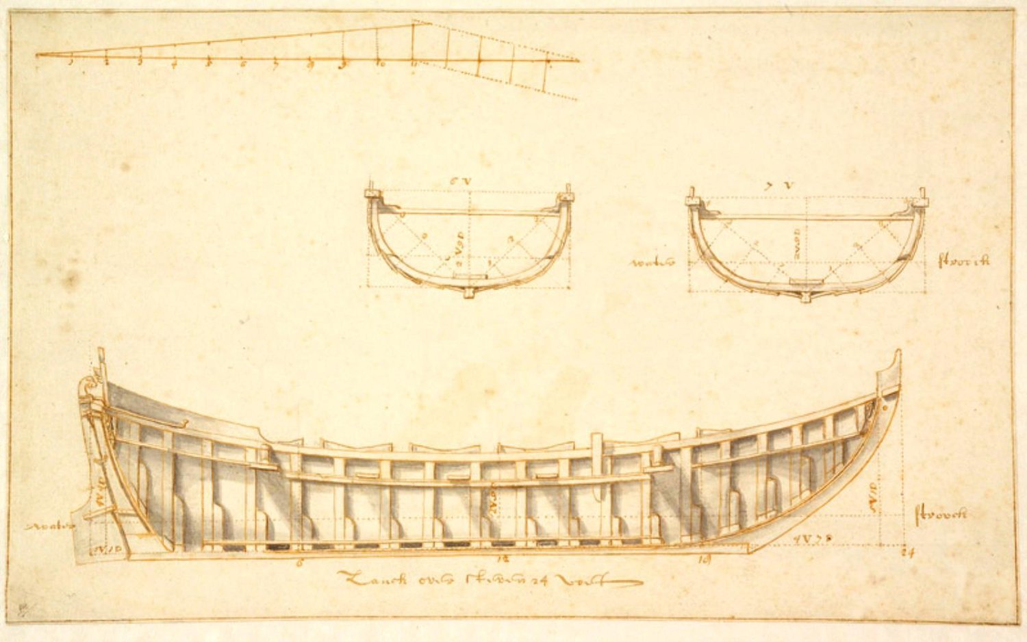
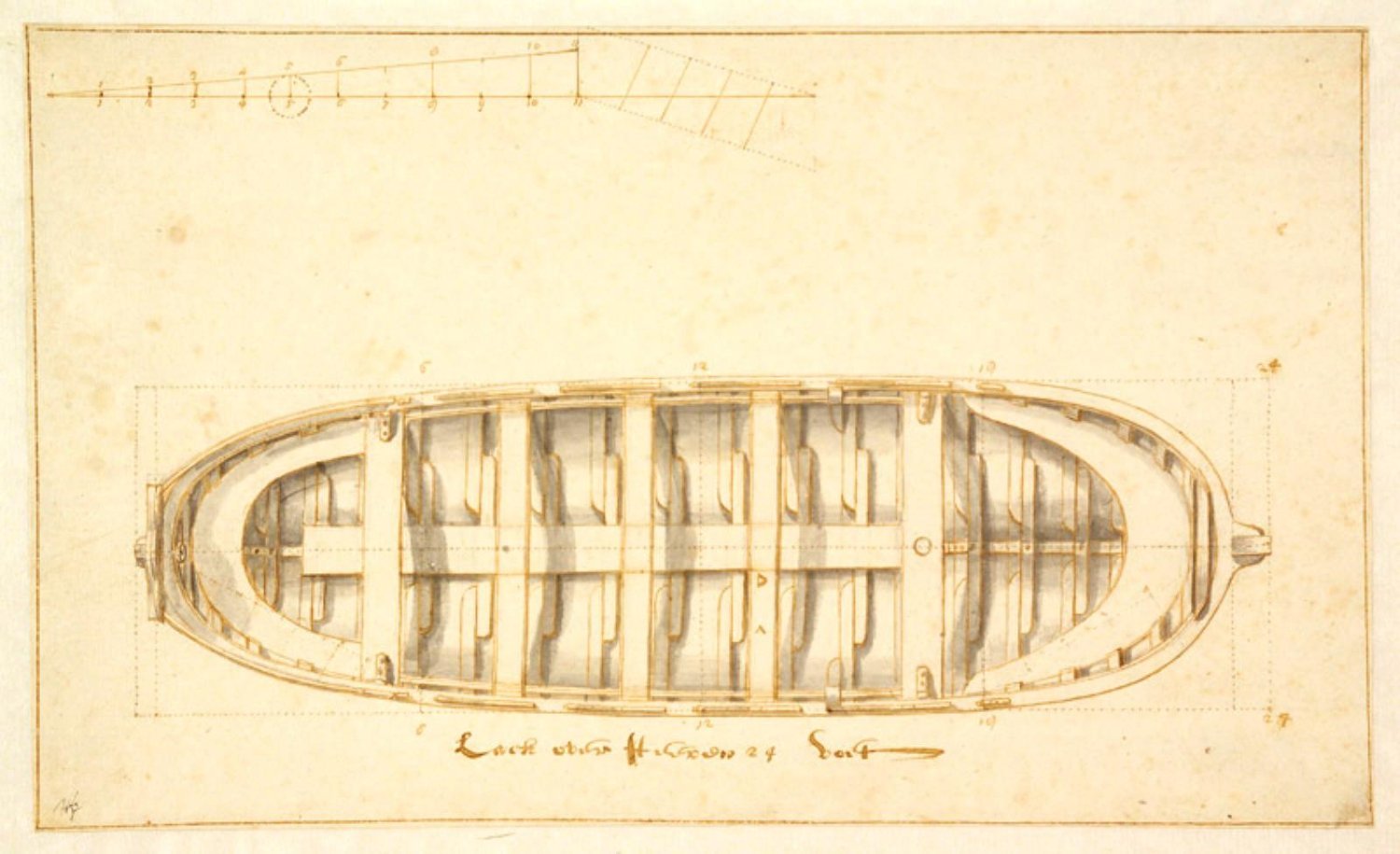
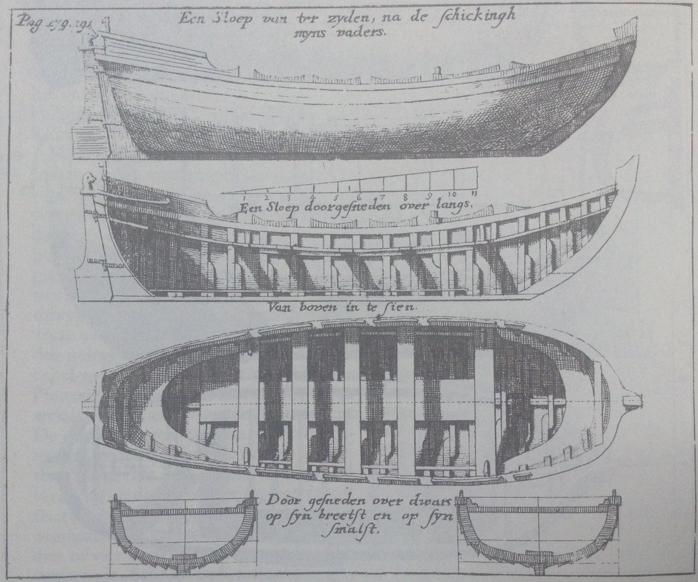
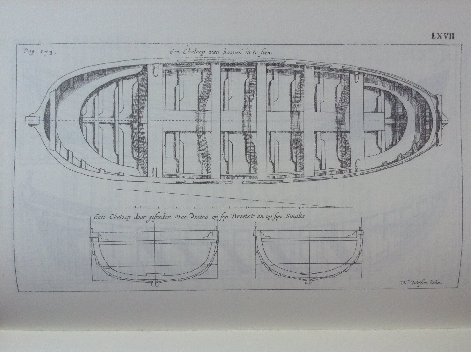
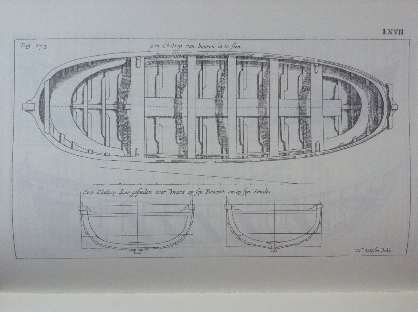
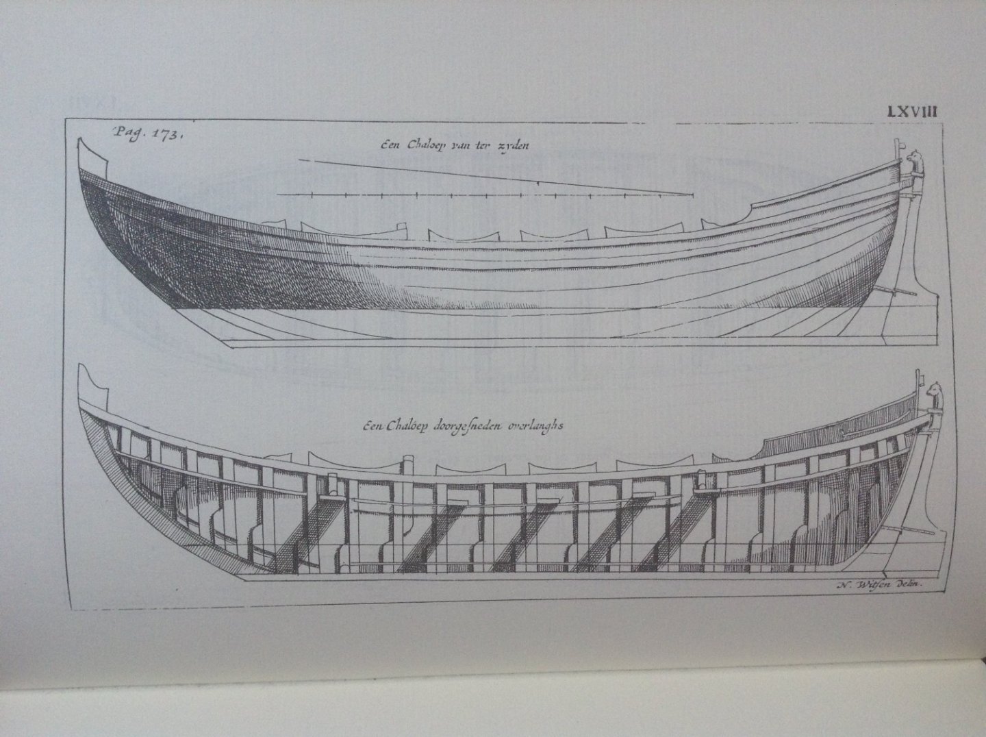
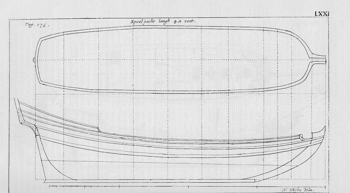
Hello all, In the last post we found the first location of the 'ground-rules and drawings' designed by Cornelis Jansz Witsen in the two books about Dutch shell first shipbuilding written by his son Nicolaes Cornelisz Witsen: the specifications and the accompanying technical drawing of a boat of 32 feet. Let's have a look at the second location. The plate of a sloop of 24 feet, 1690 A text on a plate of a sloop in Nicolaes Cornelisz Witsen's book of 1690, placed between pages 178 and 179, shows that this sloop was designed by his father Cornelis Jansz Witsen. Here is that plate: The text at the top of the plate reads: "Een Sloep van ter zyden, na de schickingh myns vaders." Which I would translate with: "A Sloop from the side, after the arrangement of my father." The other texts on the plate read: "Een Sloep doorgesneden over langs.", "Van boven in te sien.", and "Door gesneden over dwars op syn breetst en op syn smalst." Which I would translate with: "A sloop cut lengthwise", "Seen from above", and "Cut across on its widest and on its narrowest." As we can see, the plate of the sloop also contains a foot scale with a length of 11 scale feet and a height of 1 scale foot. The five views of the sloop with the foot scale are related to the specifications of that same sloop. These can be found on page 191, I, of Nicolaes Witsen's book of 1690. The title Witsen chose for those specifications is simply: "Maat van een Sloep." My translation: "Size of a Sloop." Afther this title Witsen gives the specifications of the sloop (my translation, only the first lines): "A Sloop, long over all 42 feet, may be wide 9 feet: its flat, wide 7 feet, is underneath the wale deep 2 feet, the rest is deep 3 1/2 feet: ...". After presenting the specifications of the sloop, Witsen refers to the five views of the sloop, like this: "De gestalte van deeze Sloep staat vertoont op de nevens gaande plaat, en zulks op vyf byzondere wyzen." My translation: "The appearance of this Sloop is shown on the included plate, and thisin five separate ways." From this it is clear that the specifications of the sloop with a length of 42 feet belong to the five views of the sloop on the plate. But, there is a problem. When we look at the technical drawing of the sloop, and use the foot scale on that drawing to measure the length of the sloop, we find a length of the sloop of only 24 feet, not 42 feet as is mentioned in the specifications. We have to conclude that the length given in the specifications is a mistake. The length of 42 feet should read 24 feet. The plates of a sloop of 24 feet, 1671 The specifications of the sloop of 24 feet and the accompanying five technical drawings are also included in Nicolaes Witsen's book of 1671. In his introduction of chapter 13, page 169, Witsen introduces the sloop like this: "Hier op volgt de Chaloep, met een zeer volmaakte afteekenig der zelve." Which I translate with: "Next follows the Sloop, with a very perfect drawing of the same." The specifications of the sloop can be found on page 173, I. Here are the first couple of lines of those specifications (my translation): "A Sloop 42 feet over all, is wide 9 feet: its flat wide 7 feet, is deep under the wale 2 feet, the rest is deep 3 1/2 feet: the Stern-post is high 5 1/4 feet, it rakes 2 feet: ...". We see that the mistaken length of 42 feet given in the specifications of 1690 was already present in the specifications of 1671. Here we should also read 24 feet in stead of 42 feet. In Witsen's book of 1671 the five technical drawings of the sloop are spread over two plates, the plates LXVII and LXVIII, which are placed between the pages 172 and 173. Here are those two plates: As we can see, the titles of these two plates of 1671 do not mention that the sloop is shown 'after the arrangement of my father'. This is only mentioned on the plate from the book of 1690. This concludes the description of the second location of the 'ground-rules and drawings' designed by Cornelis Jansz Witsen in the two books about Dutch shell first shipbuilding of his son Nicolaes Cornelisz Witsen. I think we can now draw the conclusion that Cornelis Jansz Witsen was not only able to make a design for a boat of 32 feet, but was also able to make a design for a sloop of 24 feet; that Cornelis Jansz Witsen was able to write the specifications for that sloop and was also able to make a technical drawing of that sloop. To be continued, Jues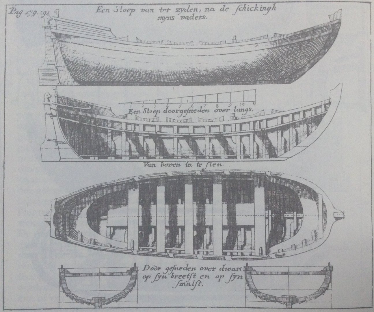
-
Technical drawings & Dutch shell first
Jules van Beek replied to Jules van Beek's topic in Nautical/Naval History
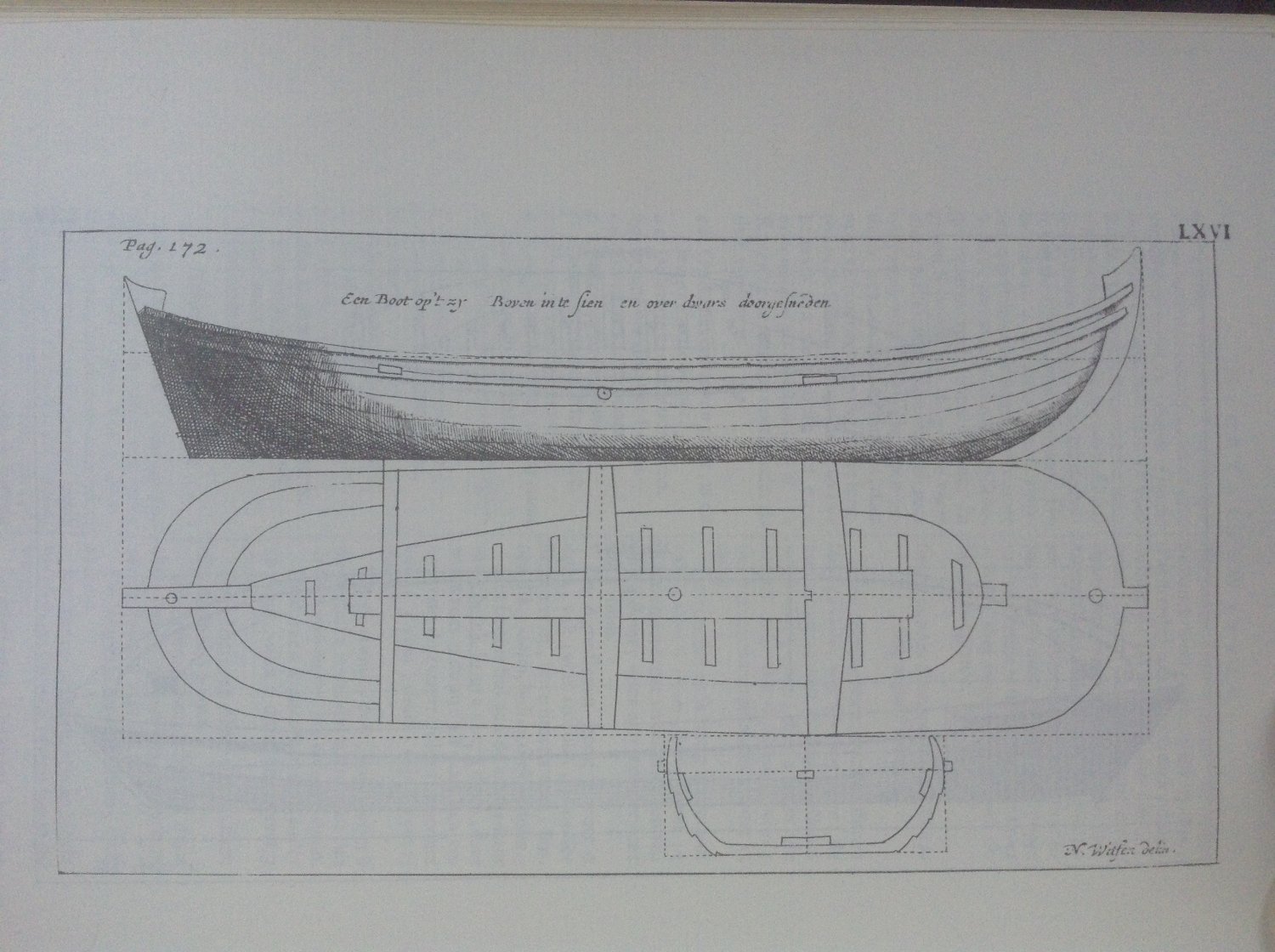
Hello all, As mentioned in my previous post, the 'ground-rules and drawings' designed by Cornelis Jansz Witsen can be found in the two books about Dutch shell first shipbuilding written by his son Nicolaes Cornelisz Witsen. Let's have a look at where we can find these 'ground-rules and drawings'. Specifications for a boat of 32 feet, 1671 The specifications for a boat of 32 feet can be found on page 172, II of Nicolaes Cornelisz Witsen's book of 1671. Nicolaes gives the following title to the specifications of that boat: "Order van een Boot, volgens de schicking mijns Vaders." My translation would be: "Order of a Boat, according to the arrangement of my Father." After this title Nicolaes gives the specifications of the boat of 32 feet. I will only give a translation of the first few lines of those specifications here: "A good boat, will be long 32 feet over all, wide 8 feet 9 inches: the beam long 25 feet 5 1/2 inches, the beam wide 5 feet 3 inches; the frames thick 2 inches, wide 3 inches, lying apart 1 foot 5 1/2 inches. The stem post is high 6 feet 5 inches, rakes 4 feet 9 inches, wide at the upper end 13 inches, at the lower end 10 inches, thick on the inside 4 inches, in the front lower end 3 inches thick. The stern post high 5 feet 9 inches, ...". Specifications for a boat of 32 feet, 1690 The same specifications for that boat of 32 feet can be found on page 190, II of Nicolaes Cornelisz Witsen's book of 1690. In 1690 Nicolaes gives a slightly different title to the specifications of that boat though: "Certer van een Boot, volgens de orde myns Vaders." My translation would be: "Specifications of a Boat, according to the order of my Father." After this title Witsen gives the same specifications of the boat as those of 1671. Technical drawing of the boat, 1671 & 1690 In both books, the one frome 1671 and the one from 1690, Nicolaes includes a plate which contains a technical drawing of the aforementioned boat of 32 feet. In the book of 1690 the plate of the boat is placed between the pages 178 and 179. In the book of 1671 the plate of the boat is called 'LXVI' and is placed between the pages 172 and 173. Here is that plate from 1671: On this plate we can find the title: "Een Boot op 't zy Boven in te sien en over dwars doorgesneden". My translation: "A Boat from the side Seen from above and cut across". That this plate belongs to the specifications of the boat of 32 feet, can be deduced from the fact that the plate of the boat is placed next to the text of the specifications of the boat of 32 feet, and that the dimensions of the boat on the plate correspond to the dimensions given in the text of the specifications of the boat of 32 feet. This concludes the description of the first location of the 'ground-rules and drawings' designed by Cornelis Jansz Witsen in the two books about Dutch shell first shipbuilding of his son Nicolaes Cornelisz Witsen. I think we can now draw the conclusion that Cornelis Jansz Witsen was able to design a boat of 32 feet. That Cornelis Jansz Witsen was able to write the specifications for a boat of 32 feet and that he was able to make a technical drawing of that same boat of 32 feet. To be continued, Jules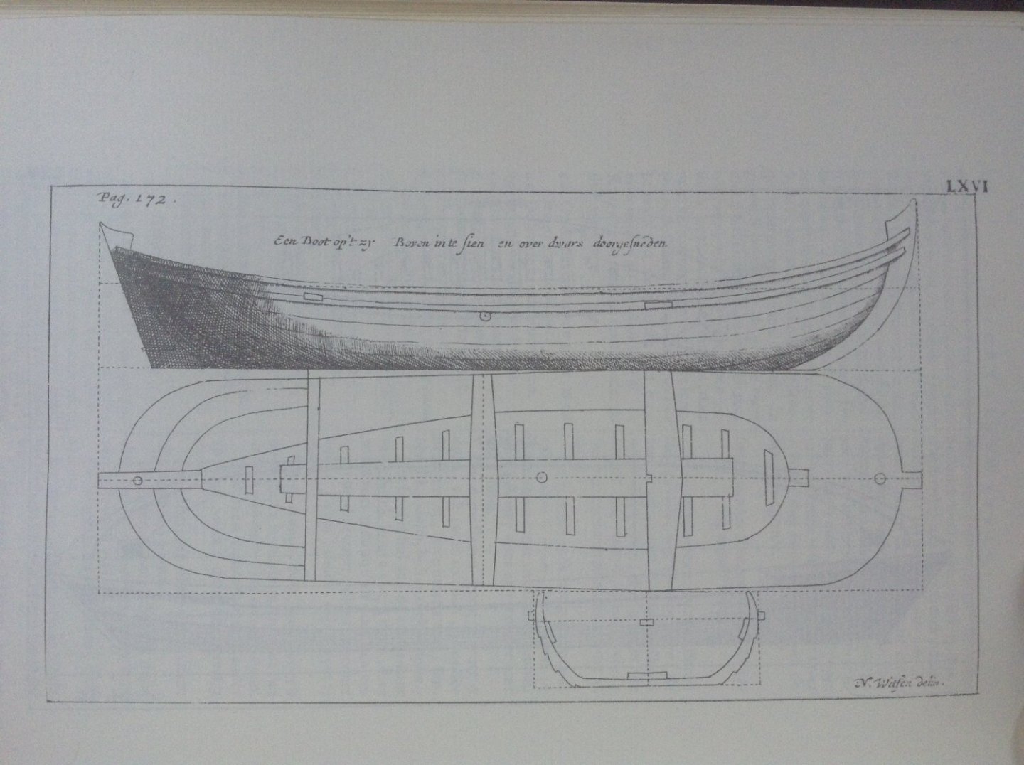
-
Technical drawings & Dutch shell first
Jules van Beek replied to Jules van Beek's topic in Nautical/Naval History
Hello all, As mentioned in my last post, Nicolaes Cornelisz Witsen mentions his father Cornelis Jansz Witsen several times in his books about Dutch shipbuilding of 1671 and 1690. Let's have a look at what Nicolaes says about his father in the foreword of these two books. The foreword of 1671 On page 6 of the foreword of 'Aeloude en Hedendaegsche Scheeps-Bouw en Bestier' of 1671 we find: "Nimmer ook zoude ik het Werk van den nieuwen Scheeps-bouw hebben durven opvatten, 't zy my in handen waren gevallen, eenige gront-slagen en tekeningen, voormaels ontworpen by wijlen mijn vader Cornelis Witsen." My translation would be: "Never would I have dared to take up the work of the new Ship-Building, if not had dropped into my hands, some ground-rules and drawings, formerly designed by my late father Cornelis Witsen." The foreword of 1690 On page 6 of the foreword of 'Architectura Navalis et Regimen Nauticum' of 1690 we find: "Nimmer zoude ik ook het werk van den nieuwen Scheeps-bouw hebben durven opvatten, 't zy my in handen waren gevallen eenige grondt-slagen, en tekeningen, voormaals ontworpen by wylen myn Vader Cornelis Witsen: en 't geene dat'er van my toe gedaan is, hebbe ik getrokken uit de mondt en ontwerp van brave Meesters; want zelver in practyk een Scheeps-timmerman of Zee-man te zyn vermete ik my niet: doch eigene bespiegeling, en ondervinding, is daar echter by gekomen." My translation would be: "Never even would I have dared to take up the Work of the new Ship-Building, if not had dropped into my hands, some ground-rules and drawings, formerly designed by my late Father Cornelis Witsen: and all that I have added, I have taken from the mouth and design of good Masters; because a Ship-carpenter or Seaman in practice I do not measure myself to be: but own reflection, and experience, is added to that anyhow." So in both forewords, the one from the book of 1671, and the one from the book of 1690, Nicolaes Cornelisz Witsen mentions 'some ground-rules and drawings, formerly designed by my late father Cornelis Witsen'. I think we can conclude from this sentence that 'father' Cornelis Jansz Witsen is the designer of the 'ground-rules and drawings'. Nicolaes is not talking about some 'ground-rules and drawings' that were in the possession of his father by chance, no these 'ground-rules and drawings' were in the possession of his father because his father had formerly designed them. I think we can also conclude that Nicolaes Cornelisz Witsen inherited these 'ground-rules and drawings', which were 'formerly designed by my late father Cornelis Witsen', from his late father Cornelis Jansz Witsen. They must have 'dropped into his hands' after his father died in 1669. Since Nicolaes Cornelisz Witsen also states that he could not have begun to write his book before the ground-rules and drawings of his father had dropped into his hands, and since we know that his book was printed in 1671, this would mean that Nicolaes wrote his book in about two and a half years. For our understanding of Dutch shell first shipbuilding it would of course be nice if we could find these 'ground-rules and drawings' formerly designed by Cornelis Jansz Witsen. And, luckily, they are easy to find: his son Nicolaes Cornelisz Witsen published the 'ground-rules and drawings' formerly designed by his late father in both his books about Dutch shell first shipbuilding. To be continued, Jules -
Hello all, Nicolaes Witsen mentions his father Cornelis Witsen several times in his books about Dutch shell first shipbuilding: 'Aeloude en Hedendaegsche Scheeps-Bouw en Bestier', published in 1671, and 'Architectura Navalis', published in 1690. Who is this 'father Cornelis Witsen' and why did his son Nicolaes Witsen mention him in his books about shipbuilding? 'Father Cornelis Witsen' is Cornelis Jansz Witsen, who lived from 1605 to 1669. Cornelis Jansz Witsen was elected mayor of the city of Amsterdam four times; for the first time in 1653. After his first year of being mayor, Cornelis Jansz Witsen is elected to be the city of Amsterdam's representative in the board of the Admiralty of Amsterdam, a governmental department of the Republic, for three years: from 1654 to 1657. During that time he occupies himself with the planning of the new shipyards and buildings for the Admiralty on the new city island called Kattenburg. His son Jonas, a brother of Nicolaes, was one of the four people to lay the first stone for the 'Zeemagazijn', the Sea Stores, which is now the 'Scheepvaartmuseum', the naval museum in Amsterdam. We can still find the weapon of the family Witsen on that building. During that same period the Admiralty of Amsterdam builds a ship which is named after the mansion of the Witsen family in Egmond aan den Hoef: Tijdverdrijf. The tafferel of the ship is adorned with a painting of the Witsen mansion; quite an honor. In 1658 Cornelis Jansz Witsen is elected to be mayor of Amsterdam for the second time. From 1659 to 1661 he is a member of the Treasury of Amsterdam. In 1662 he is elected mayor of Amsterdam again, for the third time. In 1663 he is a member of the Treasury again. From 1664 to 1666, during the second English war, Cornelis Jansz Witsen is elected to represent the city of Amsterdam in the States General, the high Government of the Republic, seated in the city of the Hague. During this time he is elected for the committee of the States General that has to make sure that the fleet is equipped properly and leaves the ports in time. Another member of this committee is 'head of state' Johan de Witt. Both gentlemen spend time in the fleet together. In 1667 Cornelis Jansz Witsen is elected to be mayor of Amsterdam for the fourth time, but on the 9th of August of that same year he accepts the function of Sheriff, the major law enforcer of the city. Cornelis Jansz Witsen is buried on the 16th of March 1669. I think it is important to understand that the city of Amsterdam had four mayors at any given time. Every year there were elections to choose the four new mayors for the coming year. So the function of mayor of Amsterdam was not a function for a lifetime. As we've seen above, Cornelis Jansz Witsen was mayor of Amsterdam during four separate periods of one year. Next to being mayor, all mayors continued running their private businesses; they invested their time for the benefit of the city of Amsterdam, which was to their benefit as well. While being mayor, Cornelis Jansz Witsen continued running his trade business with Russia. This combination of being businessman and being mayor at the same time, explains why we can find that mayor of Amsterdam Jan Gerritsz Bicker builds three ships for the king of France in 1636, while mayor of Amsterdam Abraham Pietersz Boom builds one ship for that same king in that same year. Le Cardinal was built by mayor Bicker, la Vierge by mayor Boom. An example of a mayor/shipwright can also be found in England: Sir Anthony Deane. Deane became mayor of Harwich in 1676, just before the launch of the '30 ships program' of 1677, when Deane was given part of the responsibility for deciding the dimensions of the new ships (as Brian Lavery puts it). Although we can conclude from the above that 'father' Cornelis Jansz Witsen knew what a ship was, he used them for his trade on Russia, had a seat in the Admiralty of Amsterdam, was in the State's fleet during the second English war, the above does not explain why his son Nicolaes Cornelisz Witse mentions him in his books about Dutch shell first shipbuilding. To be continued, Jules
-
Drawings of ship flags of different states. XVIII c.
Jules van Beek replied to greenstone's topic in Nautical/Naval History
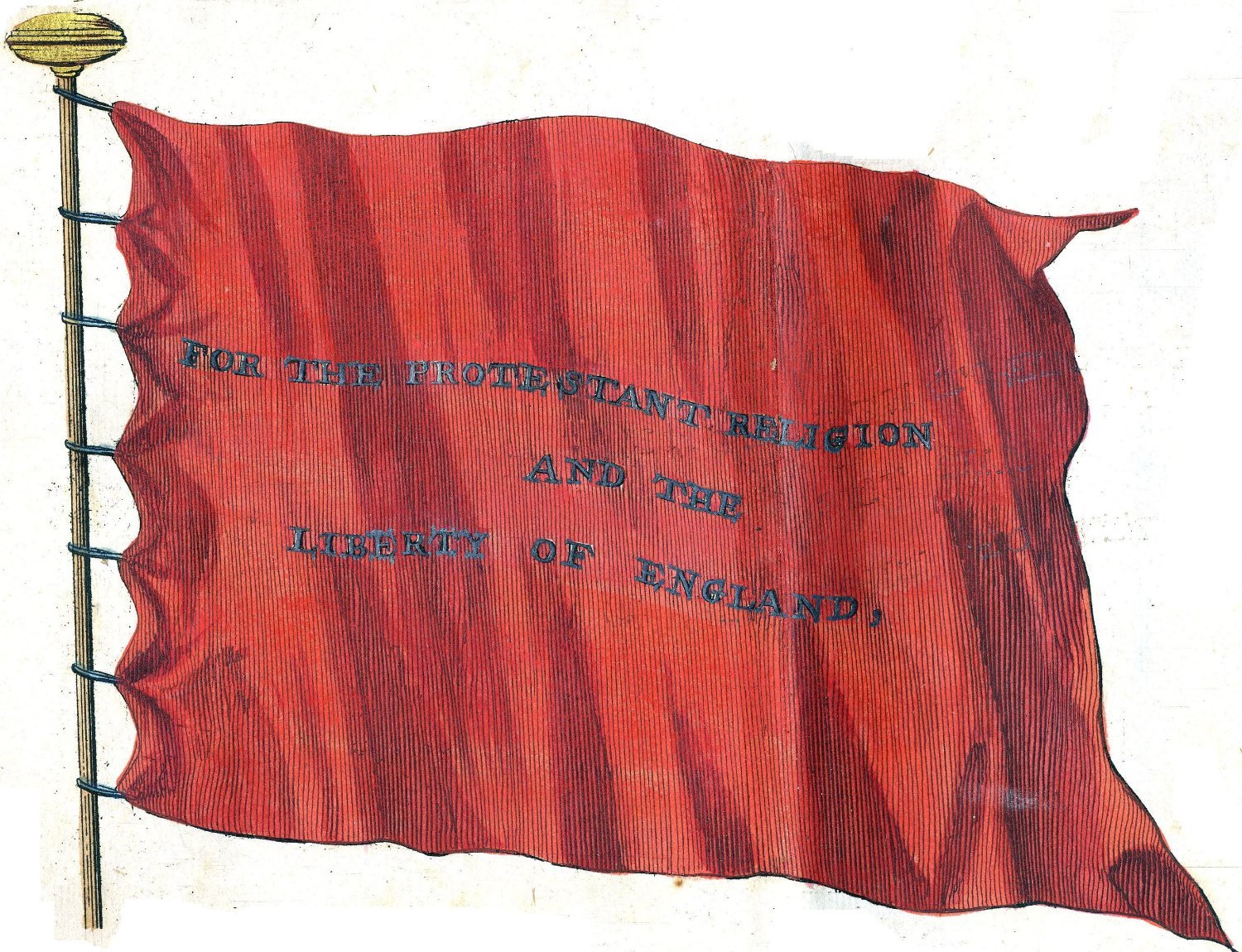
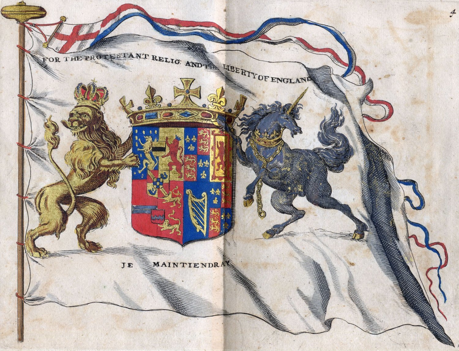
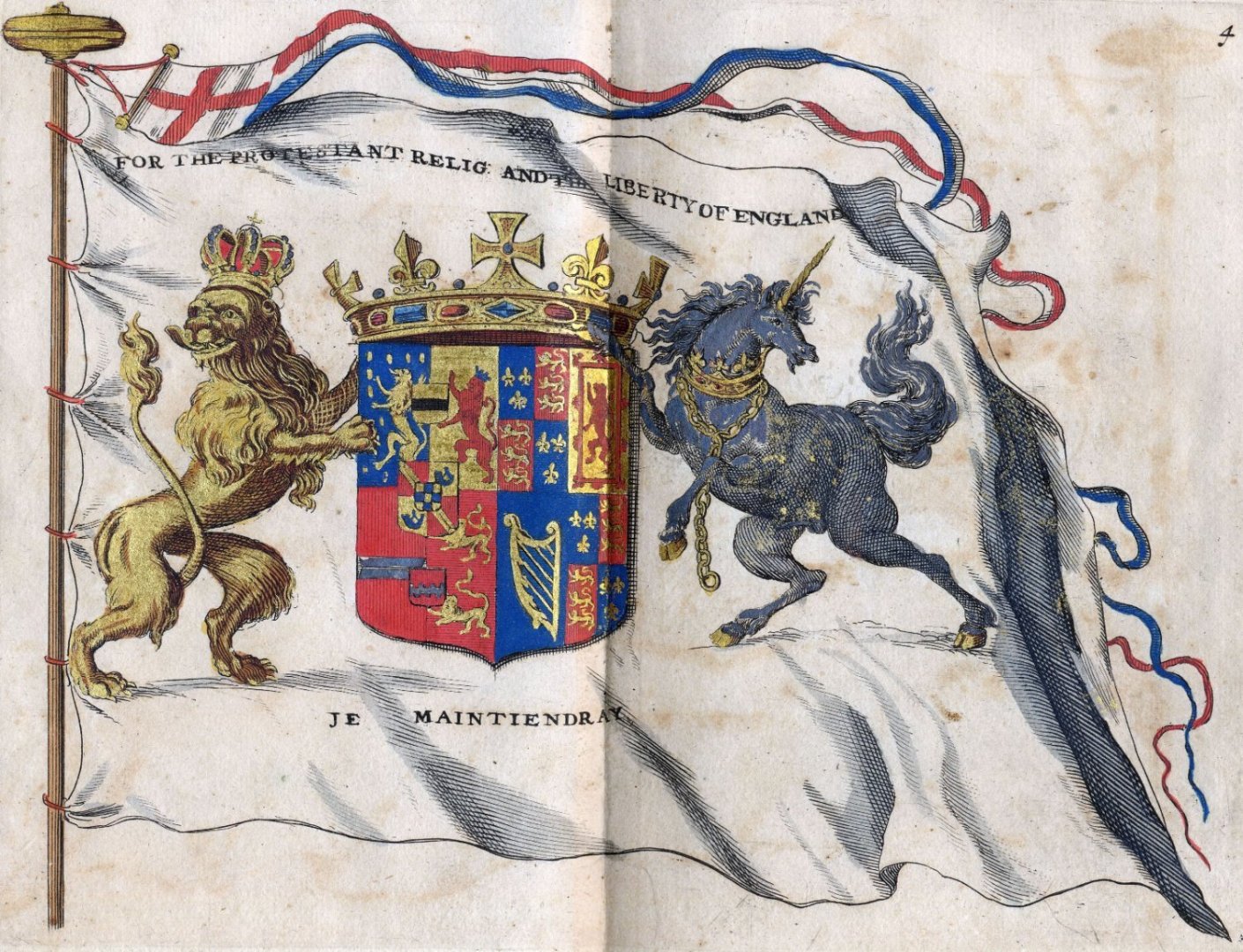
Hello Greenstone, What a great find! And many thanks for posting this here. I think the book you found in the archives contains copies of the flags Allard published in his 'Nieuwe Hollandse Scheeps-Bouw' (New Dutch Shipbuilding) of 1695. This book was, of course, printed in black on white paper, but the wealthy could have these flags painted by artists. A couple of these 'painted' books can still be found in Dutch libraries and archives. Tsar Peter probably saw Allard's book while he visited the Dutch Republic in 1697, and must have had these copies made. The book of Allard does not contain the first flag in 'your' book though, the flag of Tsar Peter I. This flag must have been made on a special order from the Tsar. This 'special' flag can also be found on the paintings that were made of the visit of the Tsar. For example on some works of Storck. The flag you want to know more about is in Allard's book of 1695. In his book it is number 5. Here it is: Allard gave the following description for this flag on page 13 of his book (my translation): "5. Unions Flag, as flown by the respective Admirals, and most important Captains in the expedition mentioned above. Being red, on which is written in white. For the Protestant Religion And The Liberty Of England." The expedition Allard mentions in his discription of flag number 5, is described in the description of flag number 4. That is this flag. Part of Allard's description of this flag number 4 (my translation again): "4. The Great Standard as flown by H. R. H. of Great Britain, when he still was Prince of Orange, City-Holder and Captain-General of the United Netherlands etc. when he sailed to England with the Assistance-Fleet, on the 11th of November 1688. Being a white flag, with the weapon, as he carried ...". Since the wrong spelling of the English words 'protestant' and 'liberty' does not occur in the book of Allard, the copyist who was hired by the Tsar must have made some mistakes. On a different note: I am sure there must be more remnants in your archives of all the papers the Tsar gathered during his stay in the Dutch Republic in 1697. With any luck there would also be the ship design drawings he made under the supervision of master-shipbuilder of the VOC (Dutch East India Company) Gerrit Claesz Pool, or the ones he made under the supervision of Adam Silo. If you manage to find these, I will be forever in your debt... But, any find from 1697 written in Dutch will be highly appreciated too. I promise to translate anything you find to English. I wish you a very good evening, and happy hunting in the archives, Jules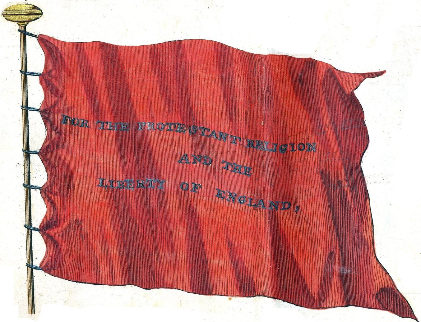
-
Hello Waldemar, Now that all your explanations of ship design methods in other threads seem to have ended, I am left with a couple of questions concerning your reconstruction of Sankt Georg. Who do you think made the design of Sankt Georg and what ship design method do you think that designer used? In your post number 97 of August 8 you say that: "Most probably the ship was built by shipwrights from Gdansk (Dantzig) and Kolobrzeg (Kolberg) and entered service in 1627. Shipwrights from Gdansk were German speaking Polish citizens ..." Does this mean the designer of Sankt Georg was Polish? Or do you think he was a foreigner? Was the ship design method he used Polish or foreign? And if he used a foreign method, how did he acquire knowledge of this method? To me these are all very interesting questions and an answer would be much appreciated. Kind regards, Jules
-
Hello Philemon, Before saying that Witsen's example ship is not a pinas, it may be a good idea to determine what a pinas actually is. I checked a Dutch dictionary from 1654 and it says: "Pinas. Spiegel-schip." My translation: "Pinas, ship with a transom." What would your definition be? Jules
- 1 reply
-
- 2
-

-
Hello Waldemar, Thank you very much for your second answer to my question in your post #103. Looking forward to your explanation of how you found the 'standard values recommended for men-of-war. I hope you agree with me that your first answer to my question in your post #102 can not be the answer to my simple question: 'would you care to explain how you decided on the shape of the main frame of your Sankt Georg?' I hope you agree with me that the answer to that question can not be: read these seven books and these Spanish government ordnances and you will find the exact same shape of the main frame as I have found. I have already read these seven books, and more, and for me it would be nice to see how you combined information spanning 100 years or so into one set of 'standard values recommended for men-of-war' in 1627. I never managed to do so, and, what's more important, and please correct me if I'm wrong, nobody else seems to have managed to do so. That's why I'm asking ... One more question. Could you explain why you did not include Dutch sources in your reading list? Where is Witsen's work of 1671? Where are the contracts for Dutch warships of this period? To me it would be more obvious to include sources from the north of Europe then sources from the south of Europe and England, especially when you seem to be using Dutch sources for the reconstruction of almost every other part of the ship. As said, I'm looking forward to your explanation of how you decided on the shape of the main frame for your Sankt Georg. Take your time! All the best, Jules P.S. Great drawing skills.
-
Hello Waldemar, Thank you very much for your elaborate reply. Before I ask you the following question I would like to emphasize that I am vaguely familiar with Dutch shipbuilding and know absolutely nothing about Polish shipbuilding; I am only here to learn, not to criticize. In your reply you state that the proportions of your Sankt Georg are quite extreme for a warship, and I think I have to agree. The 'normal' Dutch proportions, the only ones I know, are: width is a quarter of the length (ratio 4), depth is one tenth of the length. The most extreme example I could find for this period was a contract for a Dutch warship of 1626 which was 100 foot long and had a width of 22 feet. And this of course results in a ratio of 4,55; very close to your 4,62. But this Dutch ship had a depth of only 9 feet, and, what's more important, this ship had a flat bottom. In the contract it was given as 14 foot wide, and it had a width of 20 feet at a depth of 4 feet. As far as I can tell I do not see any of that in your Sankt Georg. Would you care to explain how you decided on the shape of the main frame of your Sankt Georg? I can imagine you made a calculation of the displacement of your ship, which is given as '200 last', and came to the conclusion that this had to be it. But for me, as a Dutchman, it looks as if there is not enough volume below the waterline. Kind regards, Jules
-
Hello Waldemar, Thanks for presenting your very interesting project. Would you care to share the main dimensions of the ship? Like length, width, depth and distance between decks? And it would be nice to know for me where the ship was built and by whom. Was it built by a Polish shipwright or was a foreigner hired to do the job? And, last but not least, which museum are you working for? Thanks on forehand, Jules
-
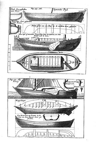
Hello Amateur, Sorry to be so late to the show. Thank you for explaining the difference between Witsen's book and Van Yk's book. You say that the vagueness of Van Yk is the reason why less models are based on Van Yk's book than on Witsen's book. But don't you think the main reason why more models are are build from Witsen's book is the fact that Van Yk's book does not contain technical drawings while Witsen's book contains a lot of technical drawings? This technical drawing of the pleasure vessel, for example: inspired the Scheepvaartmuseum to build a model in 1970, and Ab Hoving to build a model in the 1980's (Scheepshistorie 16). And the technical drawing of the 'Egmonder pinck' (at the top): inspired several modelers, like Nic Molenaar and Cor Emke, to build models of a 'pink' (Scheepshistorie 2 & 3). Without Witsen's drawings it would have been much harder to build a good model, don't you think? Jules
-
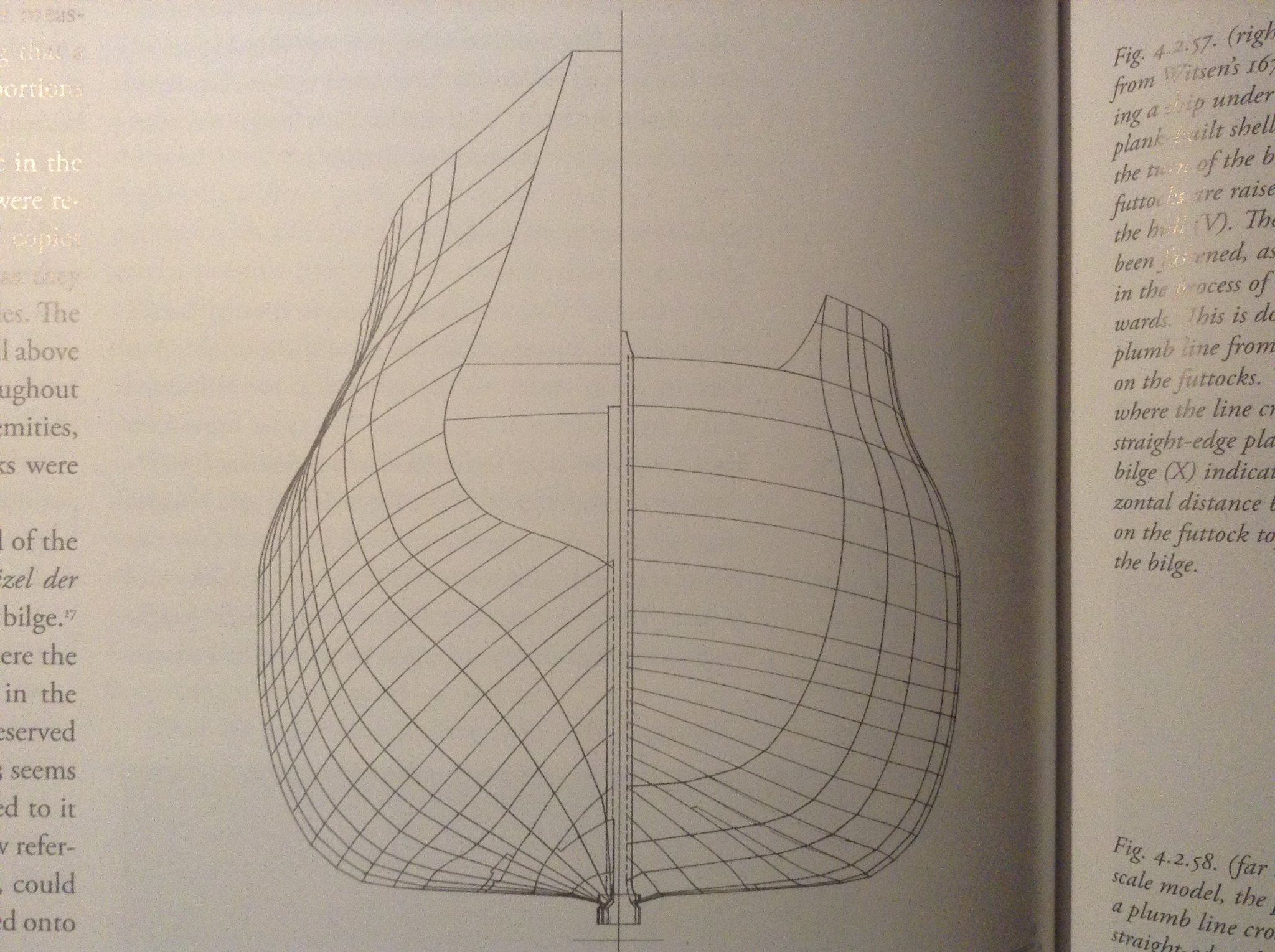
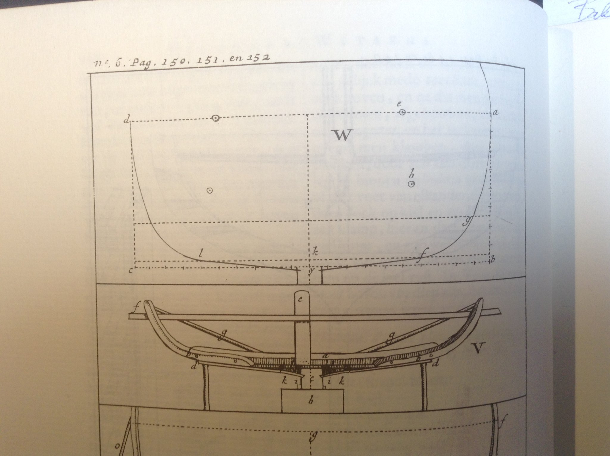
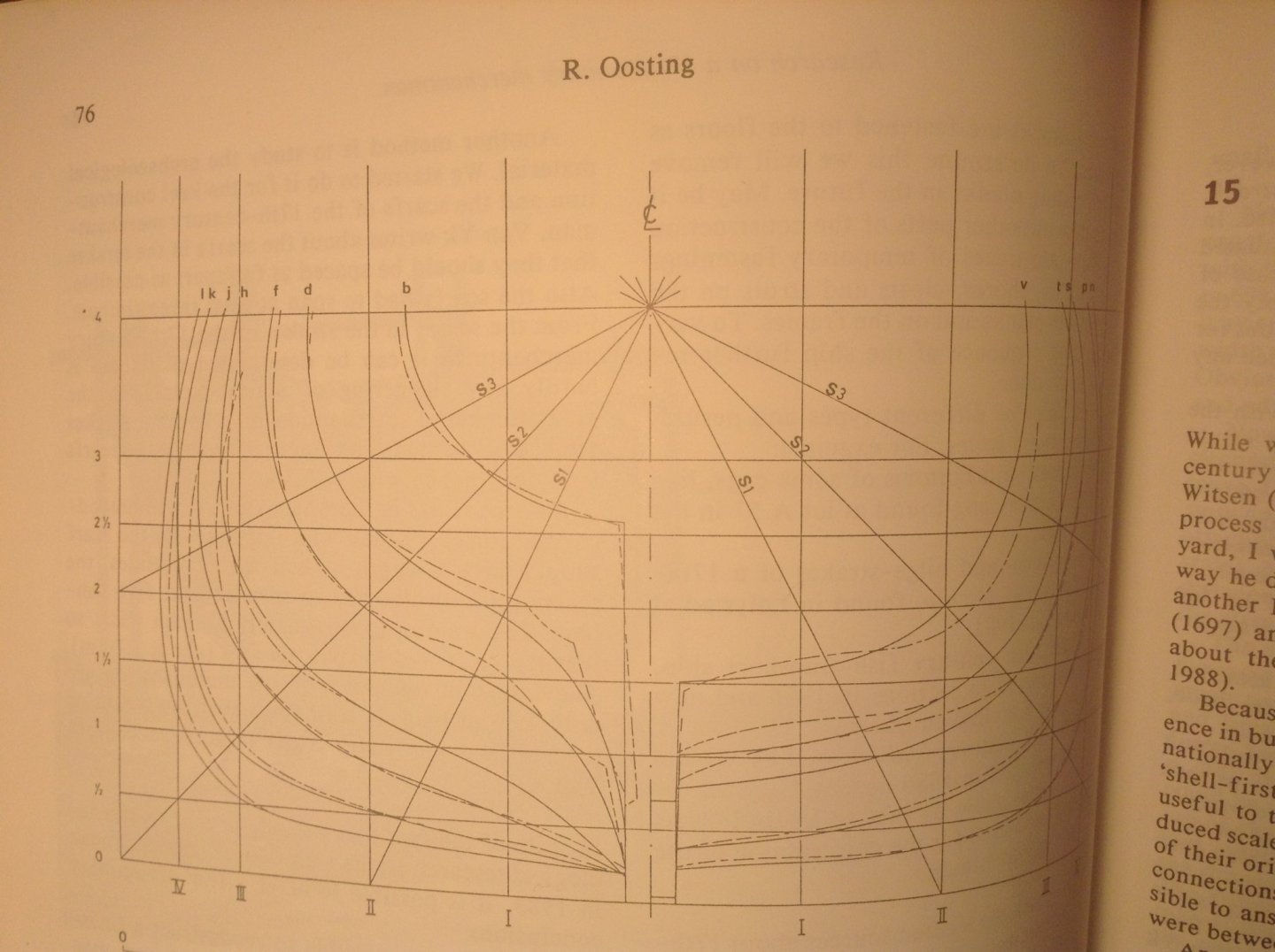
Hello Ab, I think you would be truly amazed about how easy it is to convince me. A couple of good arguments can shut me up in no time. But that's not the case yet. To get back to the subject one more time: did the building method influence the design? And, again, you stated that the building method does influence the design: building ships by using Witsen's bottom based method, would result in ships with chines. I showed you an example of a drawing from Witsen's book that shows the contrary (the statenjacht drawing), I showed you that Witsen, while talking about design, shows that round shapes were wanted (figure W), and I showed you that these round shapes could be built in actual ships from that period, referring to the wrecks B&W5, and E81. It seems to be of little consequence to what you think. But, let me continue. So, here is part of the reconstruction drawing of E81, presented by Oosting at the1988 'Carvel Construction Technique' symposium. The same symposium where you presented the results of your tests with the two building methods of the 'pleasure vessel': Here it is again: a ship built with Witsen's building method, and a round shape. Mind you, this is an actual ship from the period, not a reconstruction model you made, or a replica ship that was built while you were in the advice committee. We do not need to build models or replica's anymore to determine how ships were built while using Witsen's bottom based building method, we can simply study the wrecks. And another one of these wrecks is of course the most famous one: Vasa. Jan started this topic off by saying that he heard that Vasa was built by using Witsen's method, and that it shows no chine, and he asked: "are chine and shell-first one-to-one connected"? You chose to answer this with: "It shows how little we know". Well, in the case of Vasa we actually know a lot. Recent studies have showed that Vasa was built with Witsen's building method. Here is Batchvarov in 2012: "The research has proven that Vasa was constructed in accordance with the Northern Dutch method of shipbuilding described by Nicolaes Witsen, rather than the Southern as has sometimes been suggested." And here is Kelby Rose in 2013: "Construction features of the hull confirm that the ship was built according to 17th-century Northern Dutch methods of naval architecture." And here is Fred Hocker in 2014: "In Dutch ships, the plugged nail holes from the fastenings are the best clue to the construction method (we see these all over Vasa), ...". I think there is no more doubt about how Vasa was built, it was built according to Nicolaes Witsen's building method. And, as Jan rightfully says, Vasa's hull shows no chine. Making it clear, once again, that the chine and shell first are not one-to-one connected. To get back to the remark Batchvarov made: 'rather than the Southern as has sometimes been suggested'. I do not know who Batchvarov meant when he wrote this, who had suggested that the Southern method was used, but he could have meant you. Because this is what you published back in 1986: "Is there any value in knowing that there were two methods of building ships in Holland? I think that there is. Take, for example, the Wasa. If this ship, constructed by a Dutch shipwright, had been built in the Northern way, there would be a very obvious angle between the flat of the bottom and the bilge. There was no such angle, pointing to the fact that the shipwright must have come from the Southern parts of Holland. This is confirmed by the man's name - Hendryk Hybertsson. Hybert comes from Hubert, which is French, and this name does not occur in the Northern part of Holland. There were, of course, other small differences between the products of the two areas, but the foregoing was the main one. Such knowledge might be of help, therefore, in identifying ship models." The question now is, would you still write that today? Kind regards, Jules
-
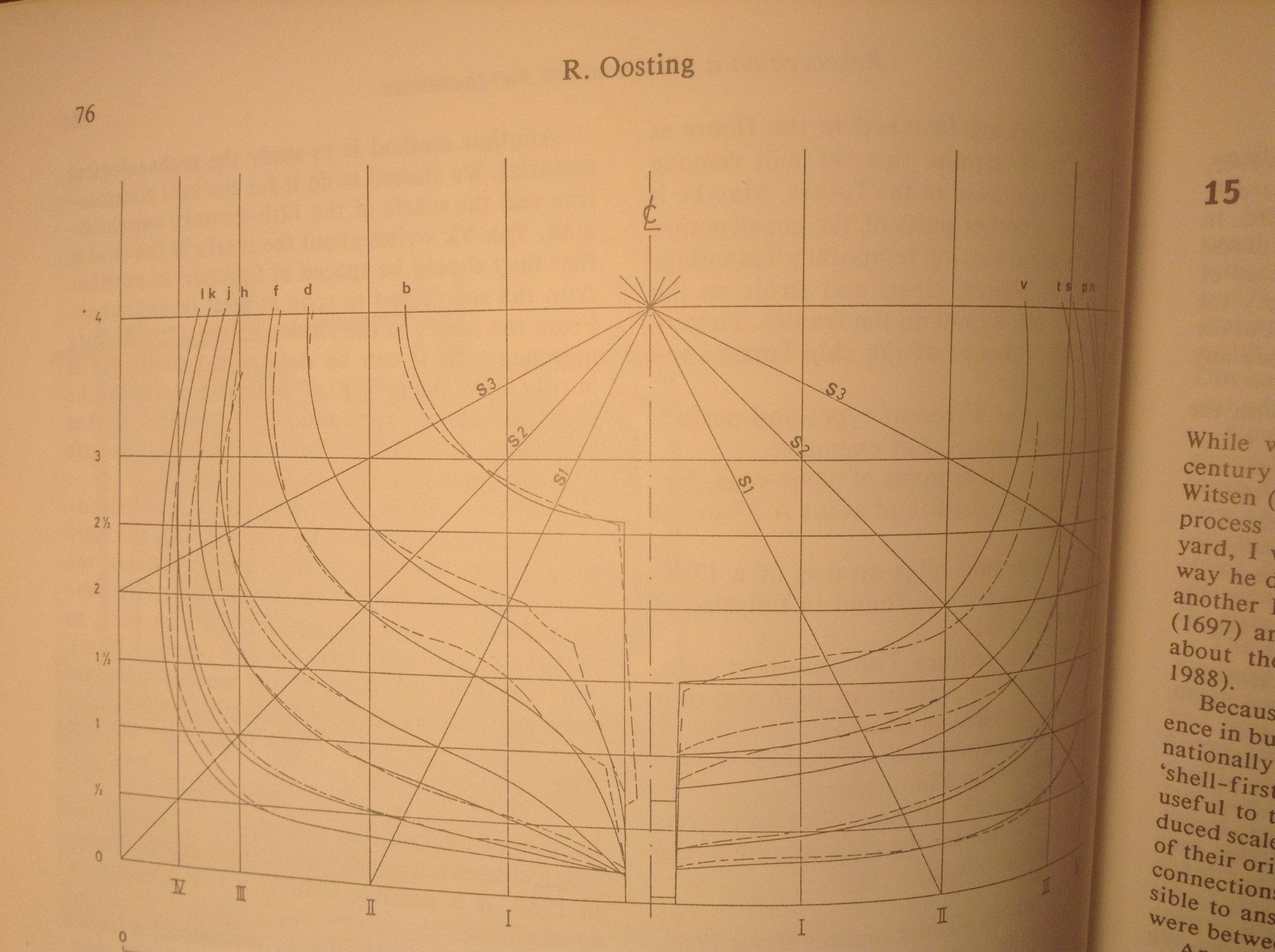
Hello Ab, We are all using the same sources, but it's the interpretation of these sources that can differ. I think it is a good thing to compare our different interpretations. And that's what we're doing here, I think. This is not an attack, I am just asking you to share your interpretations. But I hope you are willing to accept my interpretations as well. I am not trying to put words in your mouth, I am just giving you my wording of what I think you are saying; just to make sure that I get your meaning. If you do not like my wording, just say so, and correct me, please. I think I know what you mean with the chine that is a result of using straight planks to build a round bottom-bilge transition. I think an excellent example of this can be found in one of the wrecks found in Copenhagen. Here is a drawing of wreck B&W5 from Lemée's book: It was found that this ship was built with the bottom first building method Witsen describes. I think, and, again, correct me if I'm wrong, that the design intend for this ship was a round transition from bottom to bilge, and that building this round shape with straight planks led to that faceted look. For me that is something else than the chine we were talking about earlier: the clear distinction between the bottom and the bilge, the bigger angle between bottom and bilge. The key question for me is if the building method influenced the design. When we look at the figures V and W from Witsen's book, which I posted earlier, for me, it is clear that figure W shows that the design intend was a round shape, and that figure V shows that this round shape could be built. After all, if that round design could not have been built by using Witsen's bottom based building method, it would make no sense to make a round design in the first place. Who would design a round shape, if that round shape could not be built on the shipyard? And that it was possible to make these round shapes while using Witsen's bottom based building method, is, according to me, shown by Lemée's wreck B&W5, but also by the E81 wreck, which remains are now in Den Helder. Could you please give me your thoughts on this? Kind regards, Jules
-
Hello Ab, Thanks for the explanations. Much appreciated. Sorry I am insisting, but I am trying to get this right. You know where I'm coming from; still workin on the reconstruction of Gouden Leeuw, and I have to make a decision. Just like PietFriet. So, if I summarise correctly, you now seem to say that the design of the hull did not depend on the building method. It was possible to build round bottom-bilge transitions while building according to the bottom-based building method Witsen describes. The shipwright was free to choose the shape he wanted, without being limited by the building method. He could choose to make a rounded bilge, or choose to make a chine. And, for me, this is confirmed by what Witsen says about design, for which he uses his figure W. Here is his figure W: What do you think? Regards, Jules

-
Hello Ab, It is amazing how even we Dutch seem to forget about the tank tests that were done by Huygens in 1669, and about Witsen describing tank tests in his book of 1671, p.274: "In the past all sorts of shapes of ships were tested by pulling them through the water by the use of discs, to determine which ones sailed the best; the ones that moved fastest over the water, over these blocks, were considered to be the best sailers." But there is something else, something I do not understand. I hope you can help me. You say in one of your last posts: "The fact that Dutch ships showed an angle between bottom and bilge was not the result of a choice the builders had, it was simply the consequence of the method of construction." If I understand correctly, and please correct me if Im wrong, you say that the chine was an inevitable result of the building method the shipwrights used, the bottom based building method, the method Witsen describes in his book. And this would of course imply that all ships that were built using this method would necessarily show this chine. And here comes my problem: the technical drawing of the 'statenjacht' from Witsen's book I posted earlier, does not show this chine.; it shows a round transition of the bottom into the bilge. This yacht was built by an Amsterdam shipwright in Amsterdam, using the Witsen building method, but it has no chine. This, in my humble opinion, contradicts your statement. What is your explanation for this? Kind regards, Jules