HOLIDAY DONATION DRIVE - SUPPORT MSW - DO YOUR PART TO KEEP THIS GREAT FORUM GOING! (Only 13 donations so far - C'mon guys!)
×

Richard Dunn
-
Posts
529 -
Joined
-
Last visited
Content Type
Profiles
Forums
Gallery
Events
Everything posted by Richard Dunn
-
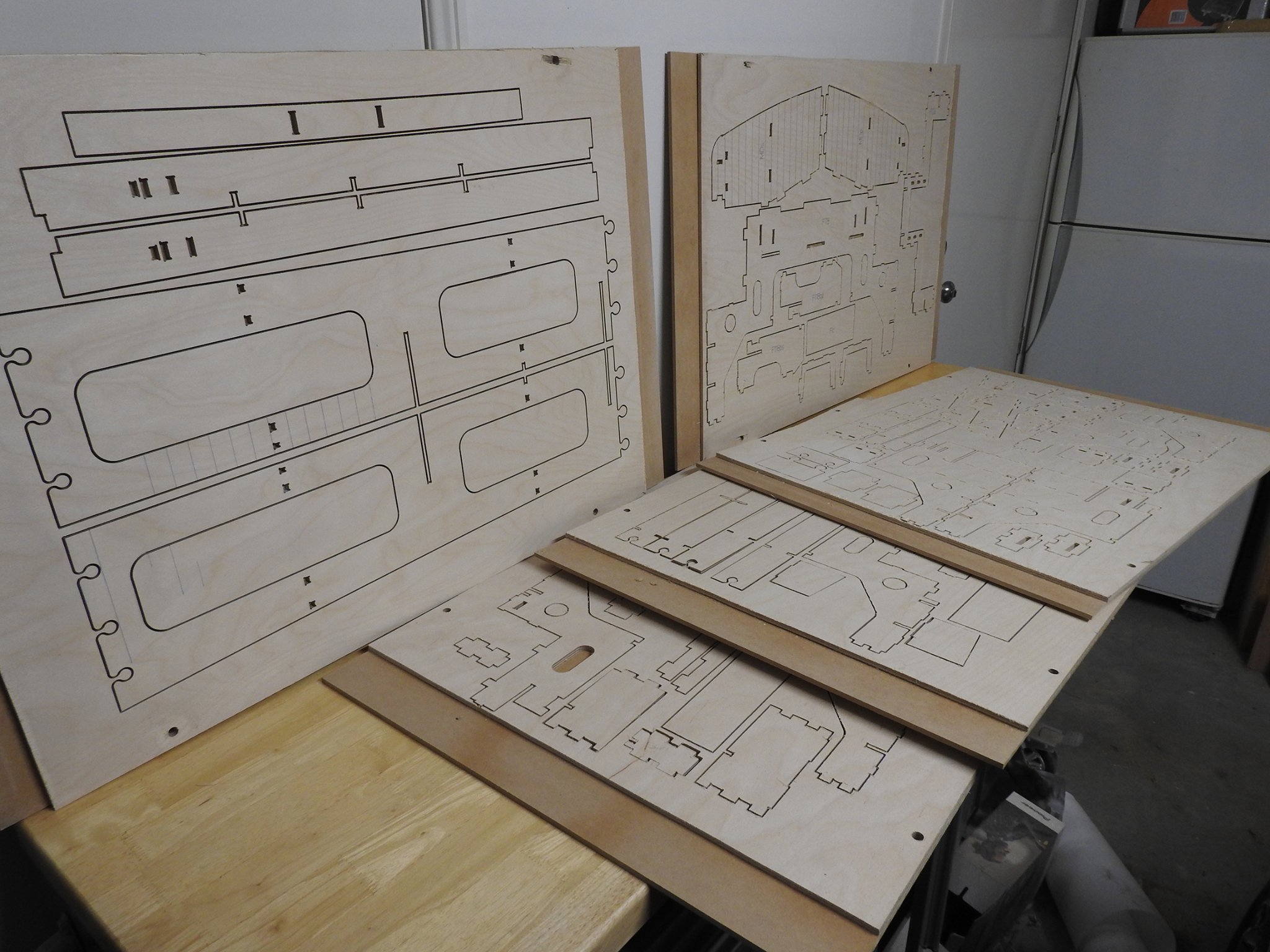
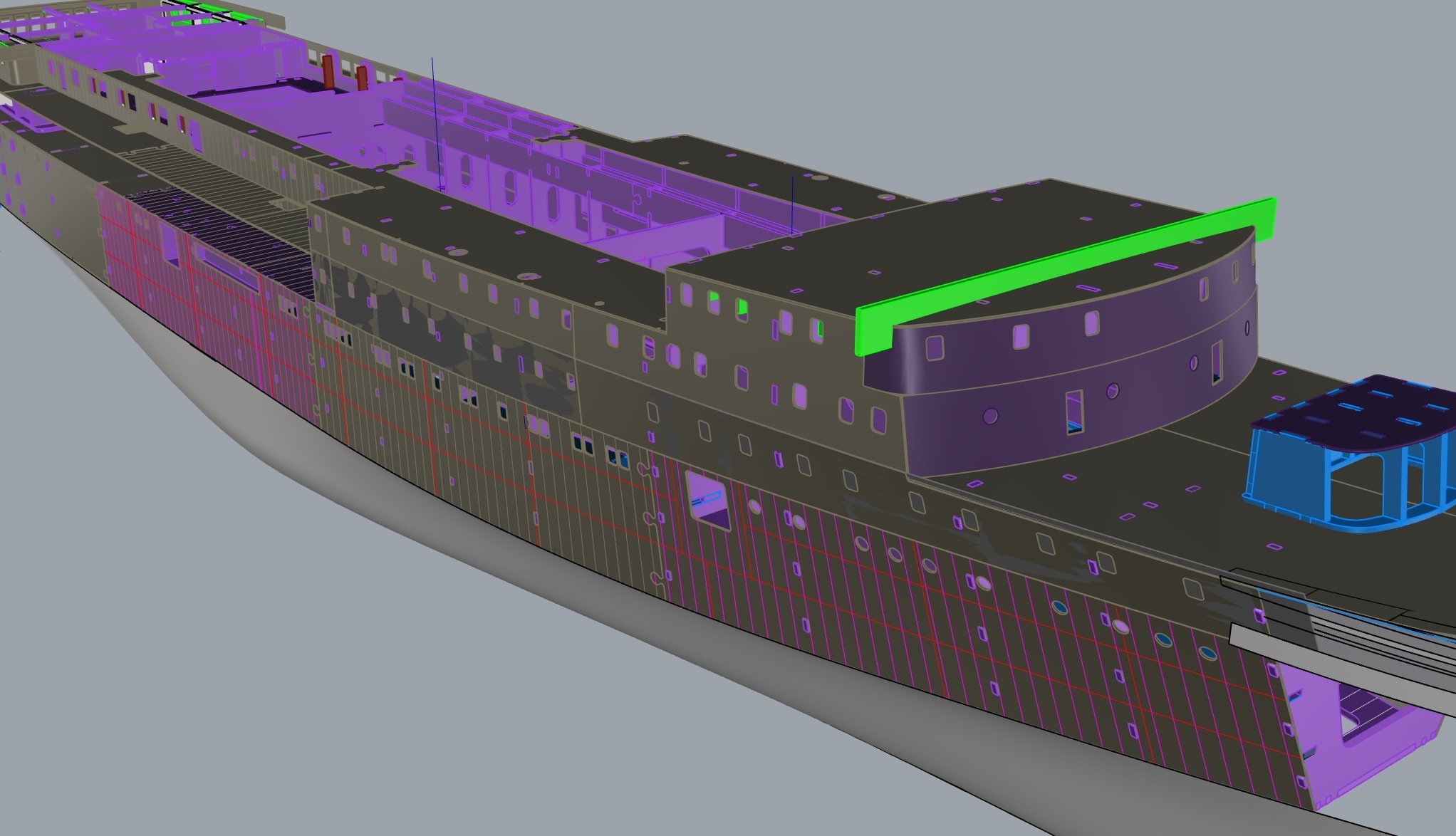
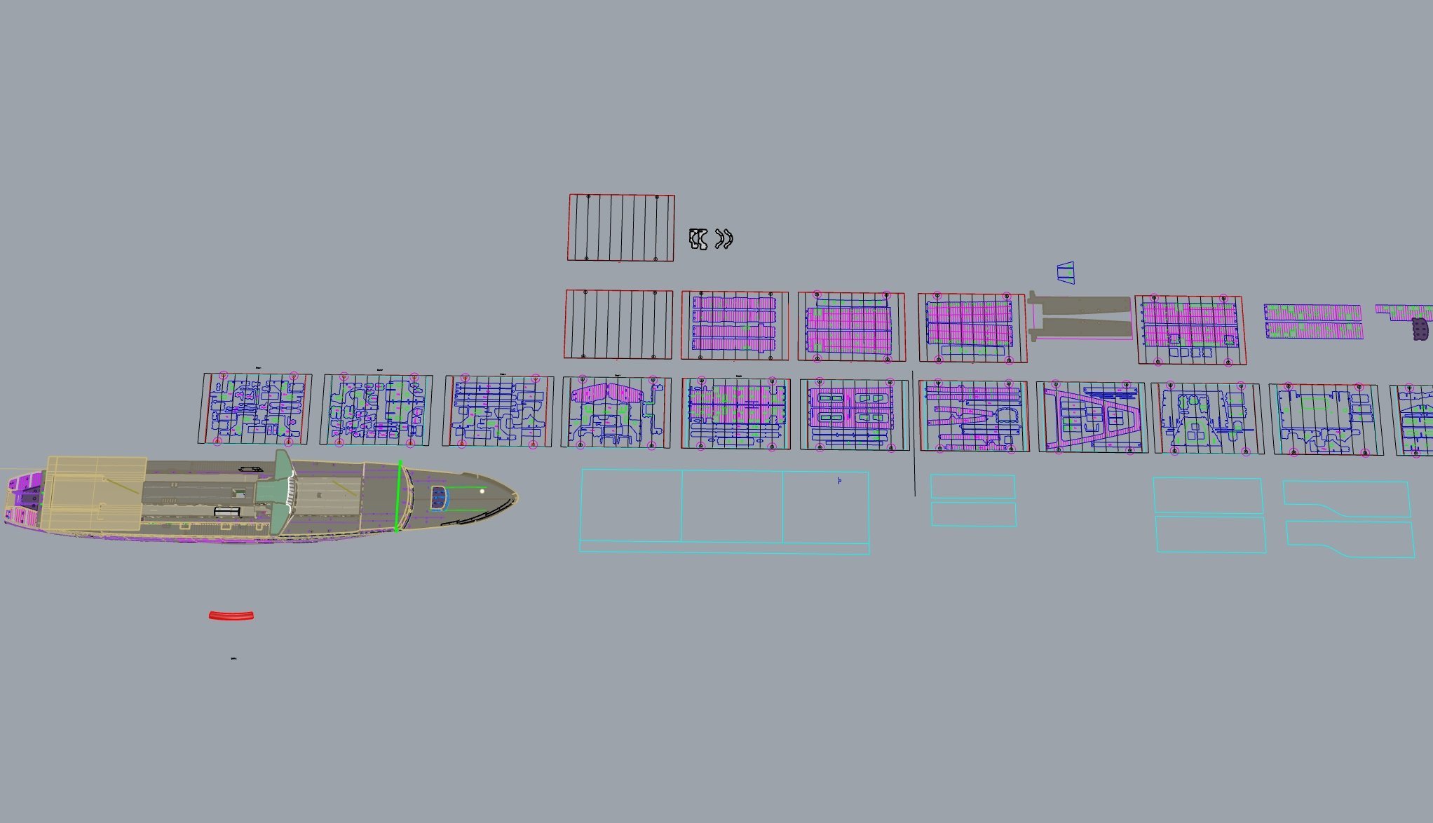
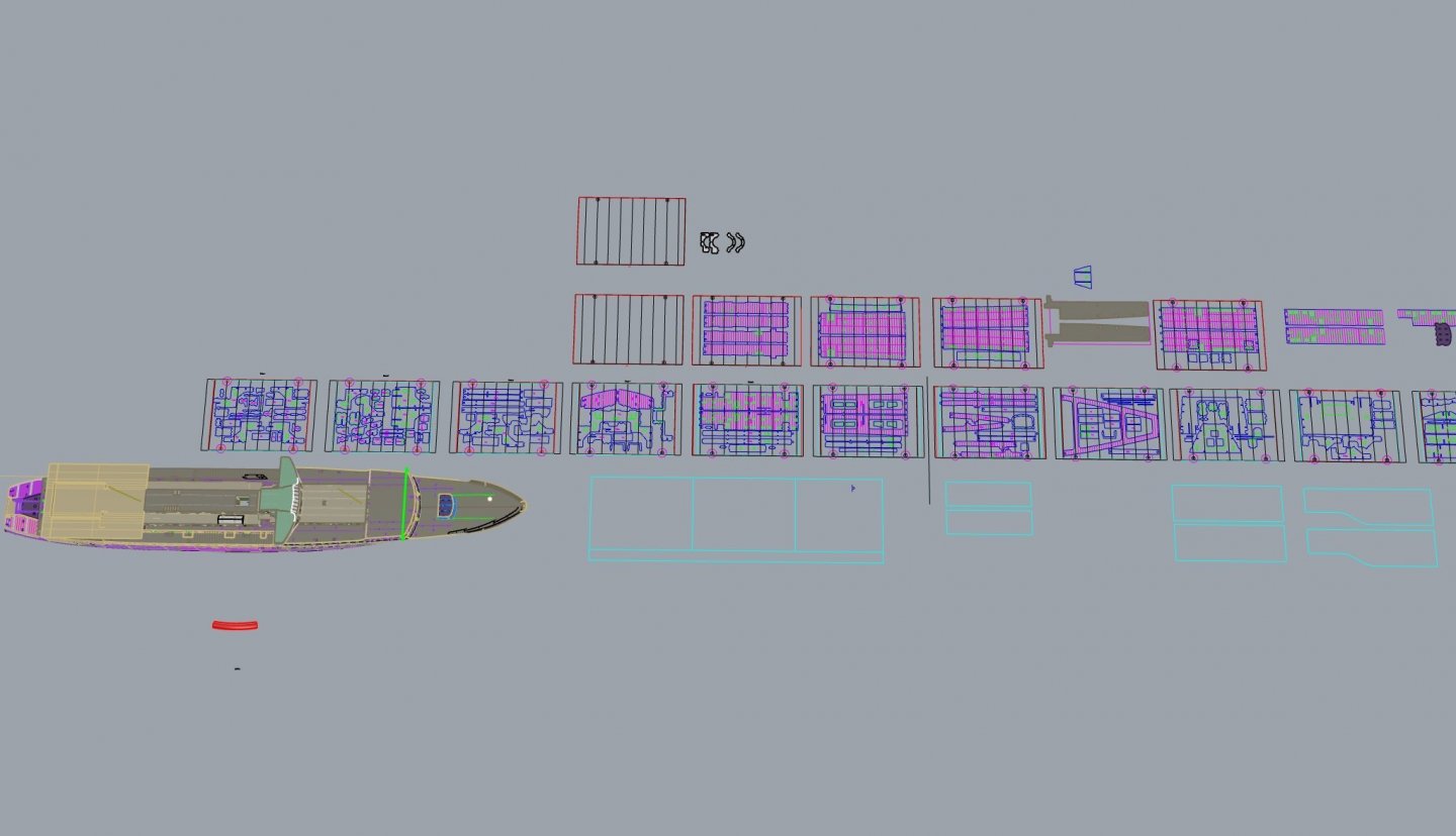
 Time for a proper post this screengrab shows the parts cut on CNC and ready to go in the pale grey brown colour, 12 sheets worth of interlocking frames
- 454 replies
-
- 6
-

-

-
- Union Steamship Company
- Stepcraft 840
- (and 3 more)
-
Yeah had a look but i need these to be 6mm deep ish and .5mm apart looks like a jig is in order and soldering it out of brass shim, ,I will make the part from photo etch and then solder, that way...oh I just had an epiphany, frame bent from one strip and blades have 2 little tabs each end that fit into holes in frame at an angle, then jig to hold it all square and solder. CNC sheets count is now at 12 sheets, another 4 done today
- 454 replies
-
- 3
-
-
- Union Steamship Company
- Stepcraft 840
- (and 3 more)
-
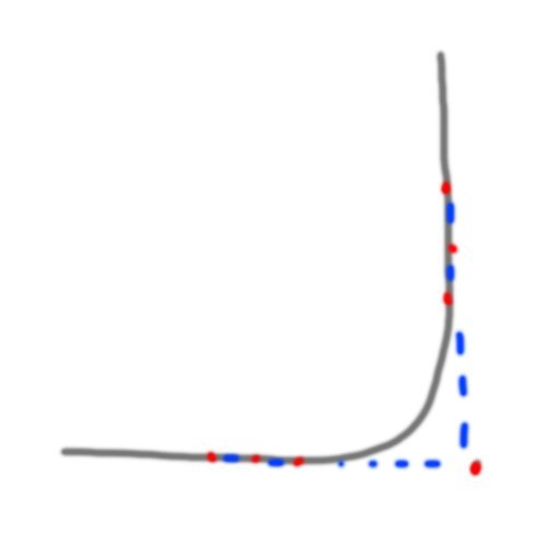
I would be inclined to return your sheer and chine curves into the centreline and form the radius so your side panel goes from stem to transom centreline. If you place your control points in the correct way you will form an arc on the corner that is nearly as good as G3 continuity. G1 means a surface is matched to the edge but does not carry on the shape, like the chine to bottom panel for example, G2 means it is Tangent matched, this means its matched only at the actual joint but is not a true curvature continuous joint and G3 means its a proper curvature match. I would assume you are planning to create the transom separately and fillet the corner which is fine to but it gets messy when you create the stern duckboard, because you then have multiple surfaces you have to join up. when you create a radius within a curve you need 2-3 points at the tangent point but along the straight (they must be in line) part and then one point out at the apex of the arc, imagine that the radius is a 90 degree corner before being filleted, you would place the point at the corner, normally you can control the weight of a point to to make the radius more or less pronounced or parabolic. This is also how you forma turn of bilge radius into the hull side and flat of bottom without having to break the curve by filleting it, the closer you slide the 2 sets of 3 points to the corner the smaller the radius.
-
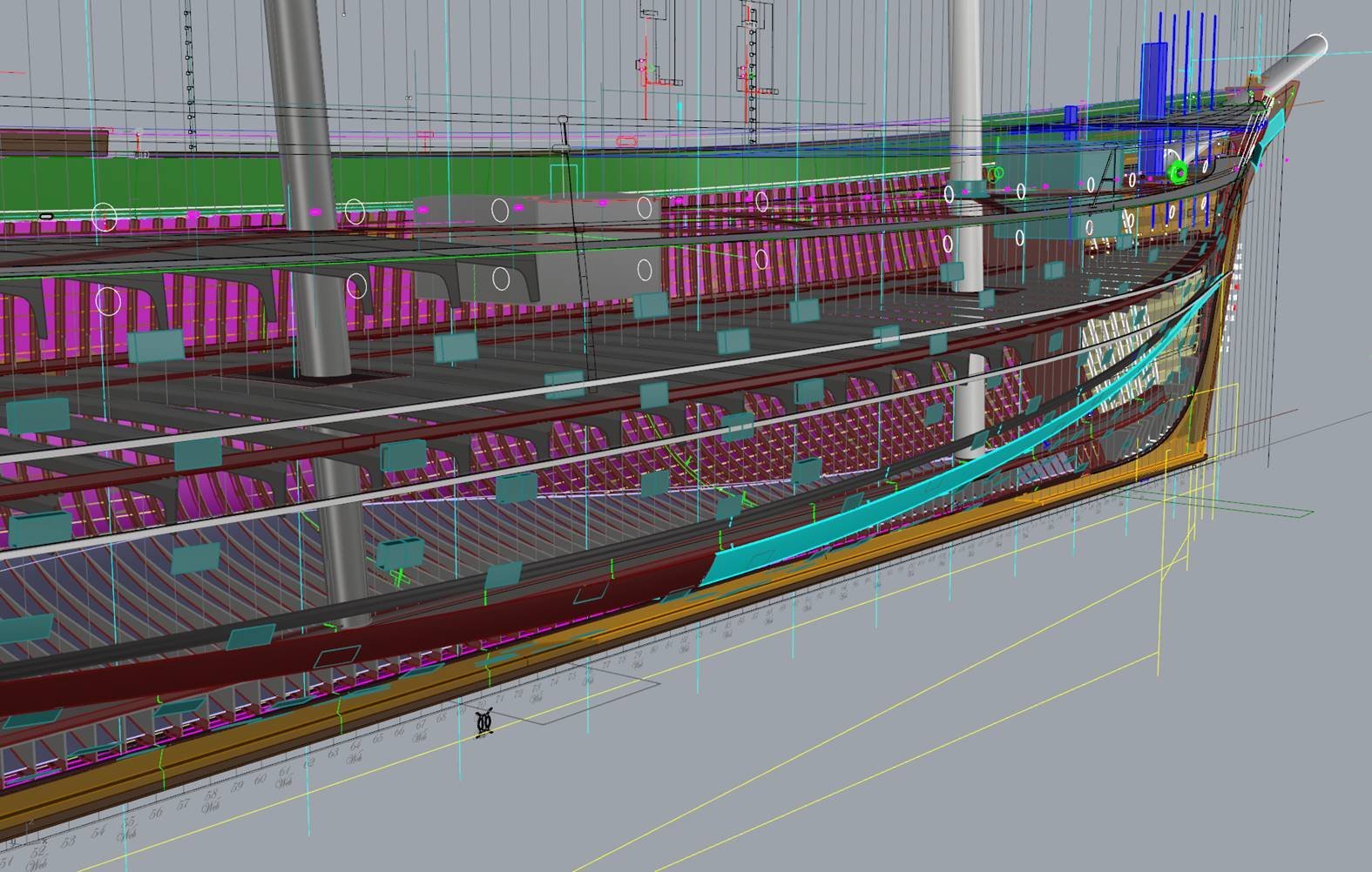
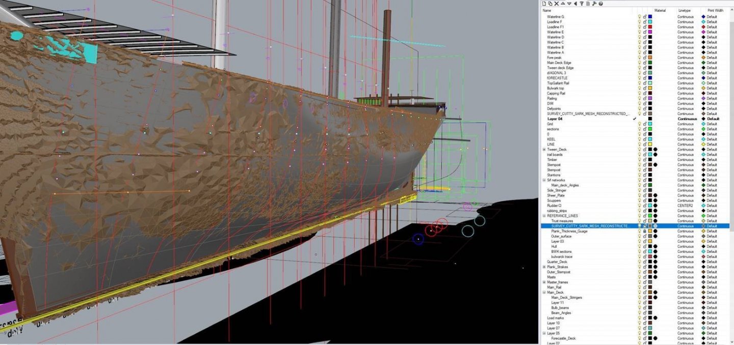
Here is a dropbox link if anybody wants it for a 3d hull model and basic superstructure, lines, stations etc for an Empire Class Tug taken from builders drawings for Empire Shirley and Jane. https://www.dropbox.com/s/muw1fkcvd63nxpi/Empire_Class_Hull.zip?dl=0 I will remove in a few days but if you get Rhino trial ( which is long)you will be able to at least see how the surface is put together, the construction lines are not there just the final result. But you could build an accurate model from this.. I am actually for my Wahine Support vessel. On he subject of 3d modelling of ships, here is another example of how its used, this was done for the 2011 Cutty Sark restoration I was involved in where I had to document in 3d from hundreds of measurements of ships frame while planking was off to capture the ships structure, I intended to do an anatomy of the ship book but it did not get approved, but this is the model and you will notice the usage of resurfacing a scanned hull of the real ship to capture true lines like never before. Sorry I will stop, I don't want to seem to hijack post but thought it might be of interest as it is relevant to the topic. Over and out.

-
The biggest thing to keep in mind is keep the number of points as low as you can, the simpler you make the cage the easier it is to tweak
-
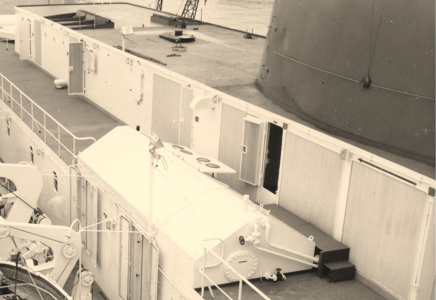
I have a question and would like to know suggestions on ways to make a very delicate and troublesome fitting. Grills The big metal finely spaced grills used into engine spaces. I need to make a lot of these with an average size of about 55mm high by anything from 12mm to 60mm wide, they are all fitted into a frame which has radiused corners, does anybody have suggestions other than brass shim and solder? I suspect the blades are bent at a 90 degree angle which would make jigging harder, or easier depending how you look at it. Image below of typical fitting Measurement from deck to deck is 69.6mm to give idea of size

- 454 replies
-
- 3
-
-
- Union Steamship Company
- Stepcraft 840
- (and 3 more)
-
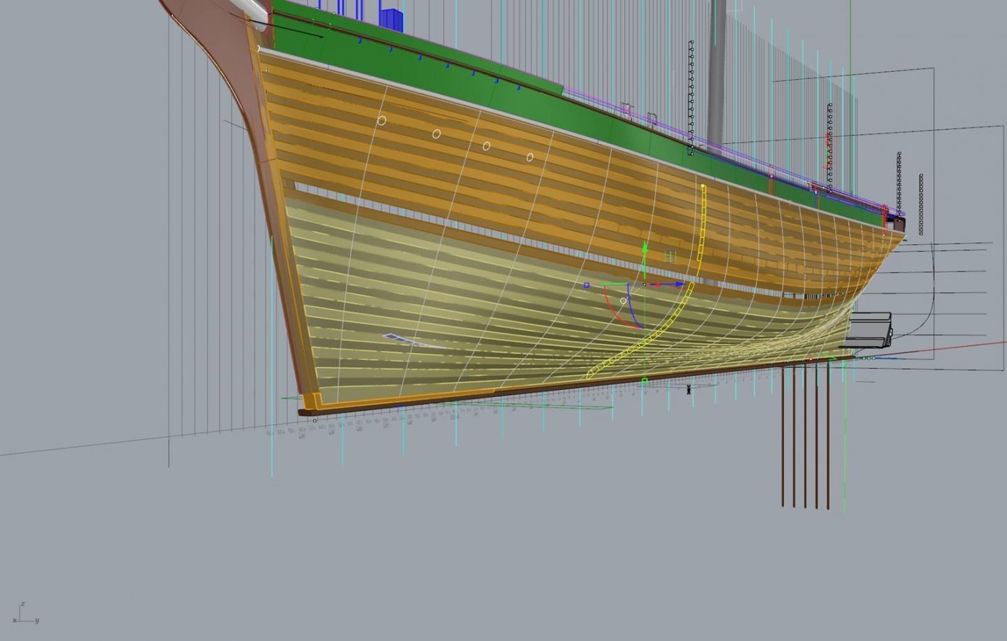
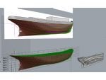
The red stations are the derived ones from the plans outlines. which then gets surfaced into this

-
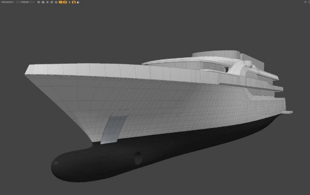
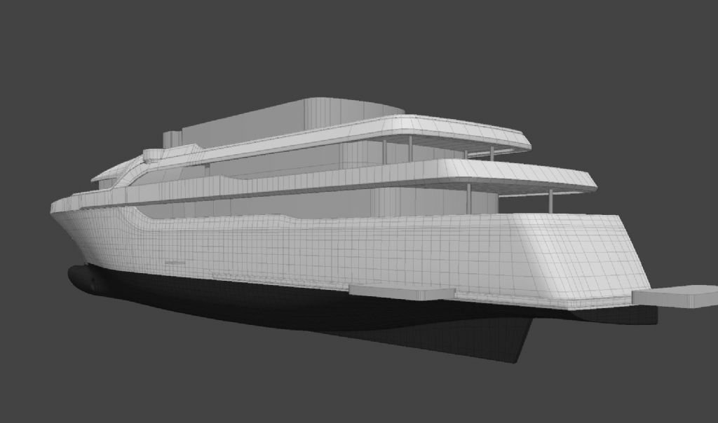
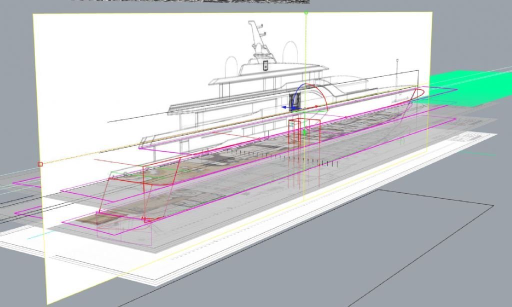
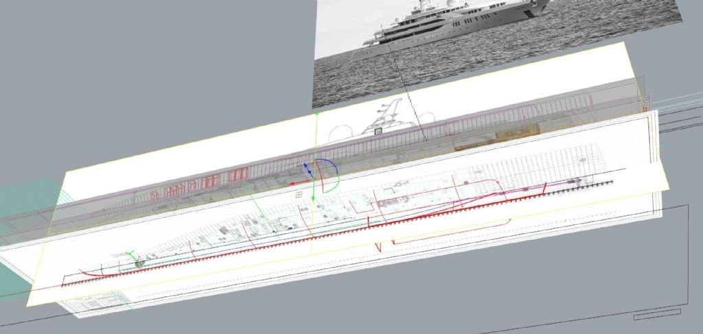
If you have some deck plans or the source of the plans is based in Cad You can get pretty close with photos of the underwater as well. I recently had to build a 3d model of the Super yacht "MY Elements" and had no plans as such but I found deck layout plans of good quality that were from a booking site and by setting those up in a 3d modelling program and fitting the surface to the edges you can get close, its the rise of floor and stern skeg areas that require the photos most of the time. Here is an example. https://camperandnicholsons.com/luxury-motor-yacht-for-sale/elements-yachtley-shipyard-turkey-2019 This is where the plans were obtained from. And after setting up the plans at the correct heights and scales the result was this, its close ,not %100 but good enough for the use I needed. I realize this involves 3d modelling but if you can do that then it is more possible. setup process looks like this
-
When I was starting out I purchased a cd from the Mcneel site which has long been out of production now but I did find this link, it might be the cheapest way to still get it but this will show you the correct way to create a hull. or many types of hulls actually but the superyacht hull is the last lesson in the set. https://www.scribd.com/doc/145007165/Rhino-Advanced-Tutorial-Marine The original was by a guy called Cliff Estes , he might have a site and have it for sale to still if you can find it, but regardless of what software you use the process does not differ much.
-
Hi Egilman I am happy to help as I do this for a living, I am a professional 3d modeller and specialise in boats and ship and architecture. If you are using those programs because you know them , great but if not you are better off with rhino3d as it is used by many Naval Architects because Nurbs modelling is the best way to do hulls and it has the ability to properly fair your lines. happy to guide you just let me know the sort of detail you have, are you using a lines plan or trying to build from deck plans, or from nothing but profile and plan which is much harder if you want to be accurate
-
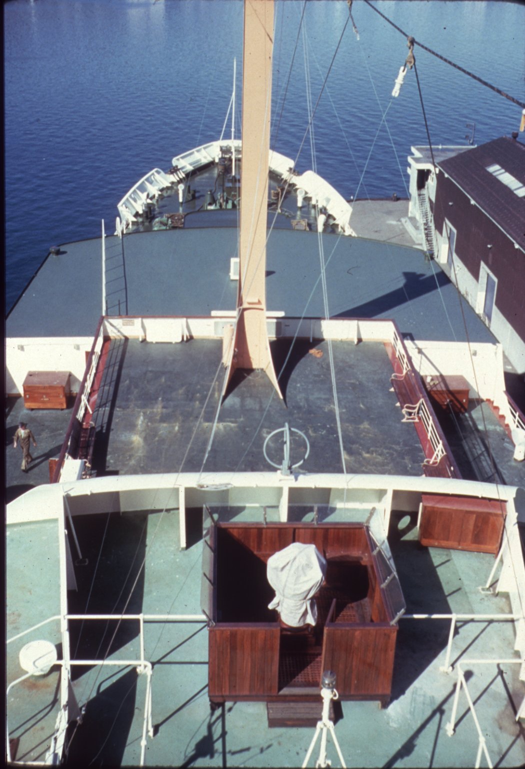
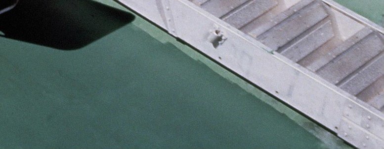
Here can be clearly seen the variation in stages of oxidisation of the decks
- 454 replies
-
- 4
-
-
- Union Steamship Company
- Stepcraft 840
- (and 3 more)
-
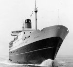
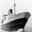
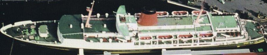
Thanks Yves Yes I suppose I am using all techniques , to be honest once the CnC is all cut sanded and removed from sheet it should take very little time to assemble and look like a ship again, the hardest part for me will be deciding when to paint each section, have had automotive acrylic paints made to the BS381c standard and will be airbrushing, though the decks which have a lot of oxidisation and touchups will have to be done with Tamiya and done by hand along with weathering techniques, the green decks always look grubby. The hull plates will be laid in .5mm 3 ply with grain vertical and the edge very lightly arissed or bevelled, the weld bead then gets glued into the slight depression left and the bead rolled with a serrated roller to give effect of weld, the tin canning effect I want to get but understate will be sanded into the high build primer by sanding between frames with finger taking advantage of the un uniform nature it will give, at least that's the theory at this stage, I have not actually tried it yet, the other is to make a rubber screed with the tin canning shaped cut in and hard filler applied to each plate once on hull though this will take a lot longer, but hull an ship will be fully tin canned as this ship had it a lot and was noticeable. I am wondering if making a scale paint roller would yield good results for deck paint to get the pattern you get with uneven coverage. The deck is a colour called forest green, its a dark almost Brunswick green but quickly goes chalky and a pale verdigris colour so was always being touched up. decks were done in a compound called Semprene which was rubber system about 1 1/2 inch thick applied to steel decks, I will be making this from 1mm ply prefinished off ship and glued into place after other paint is done on waterways and deck bars etc. Below you can see the effect, both those colours are the same paint but the bridge top is faded version, image has a cast, yes I know it looks blue but its not. the second image has no cast and is correct colours as far as photos can be

- 454 replies
-
- 4
-
-
- Union Steamship Company
- Stepcraft 840
- (and 3 more)
-
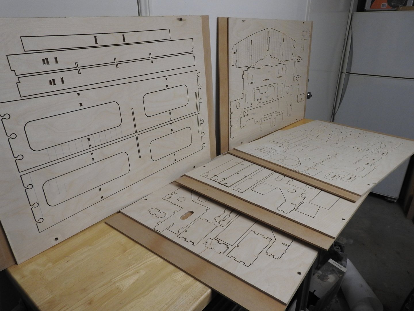
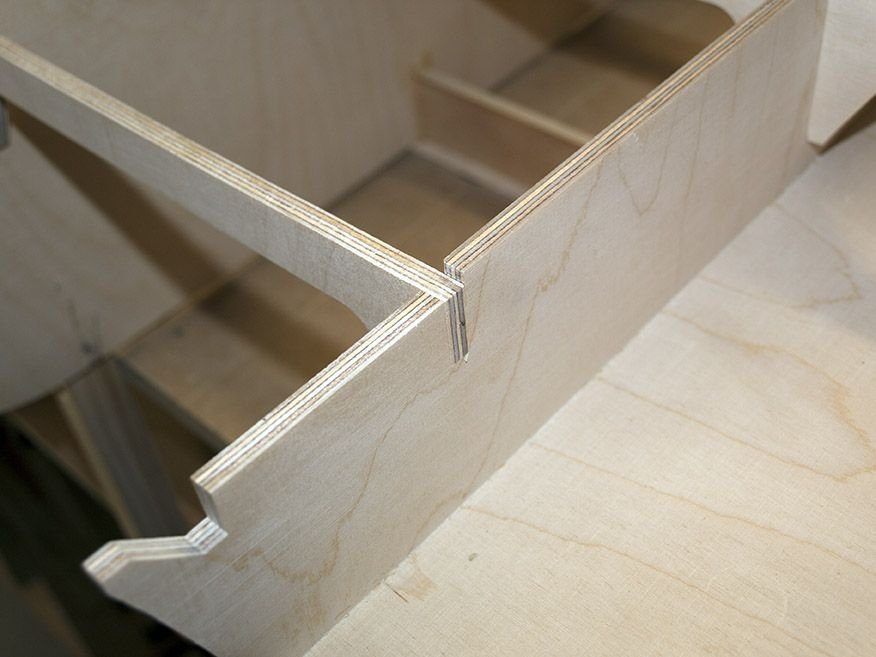
And here are the first 5 sheets of parts cut from high quality 5 ply 6.5mm Wisa ply.
- 454 replies
-
- 9
-

-
-
-
- Union Steamship Company
- Stepcraft 840
- (and 3 more)
-
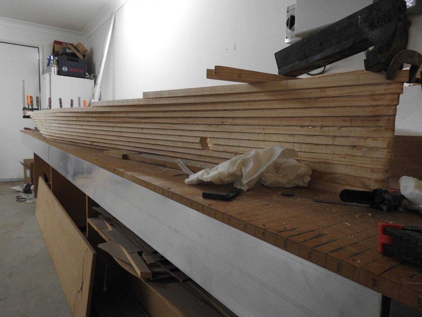
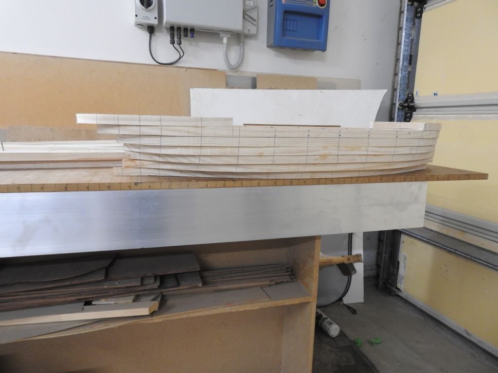
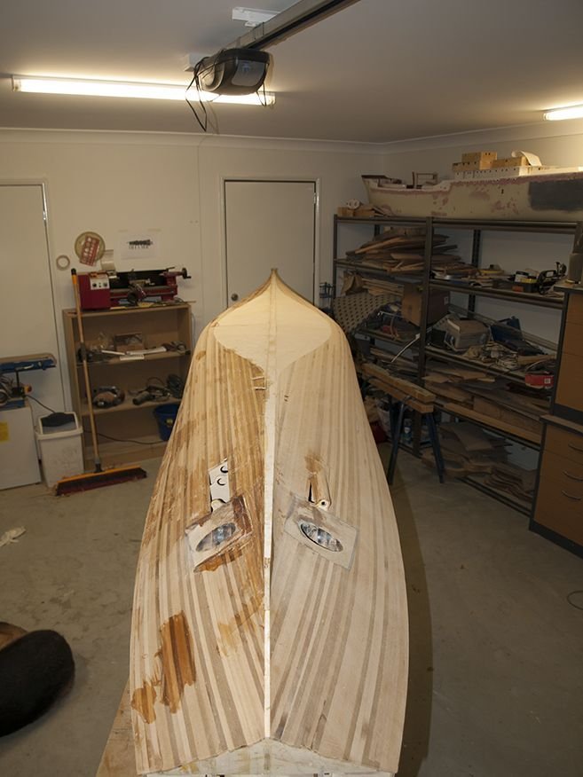
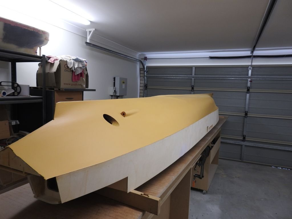
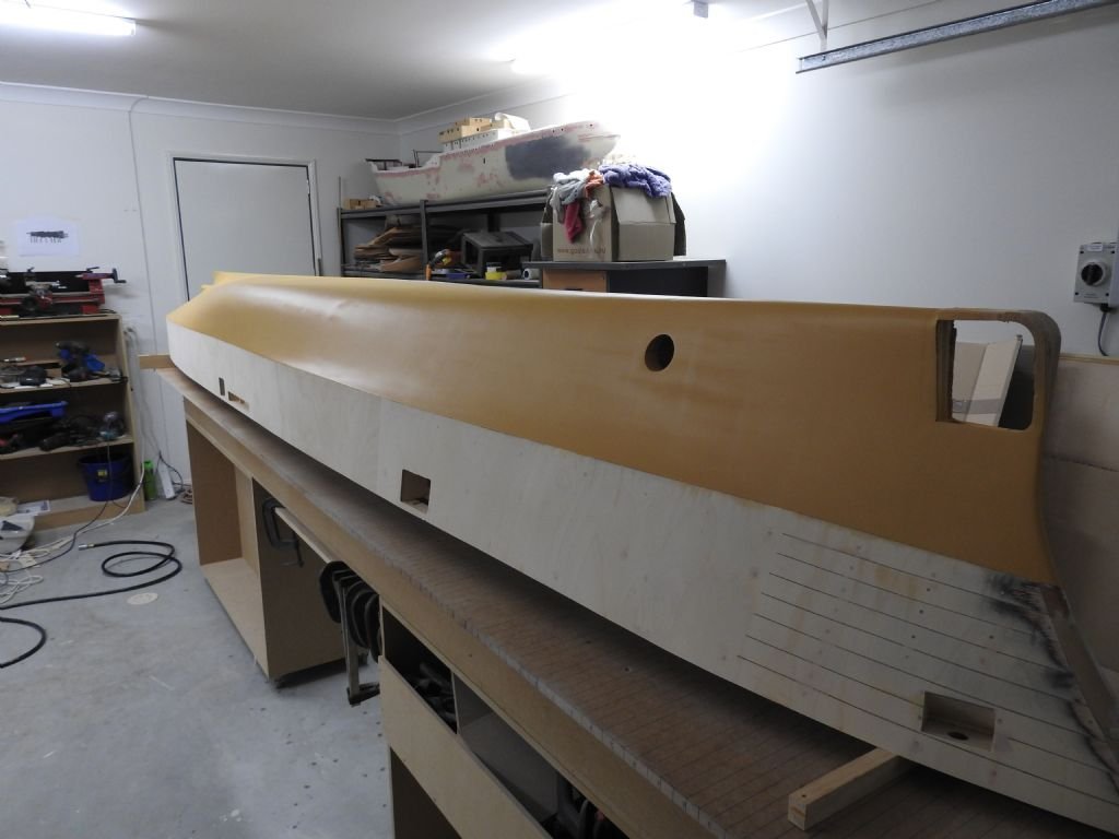
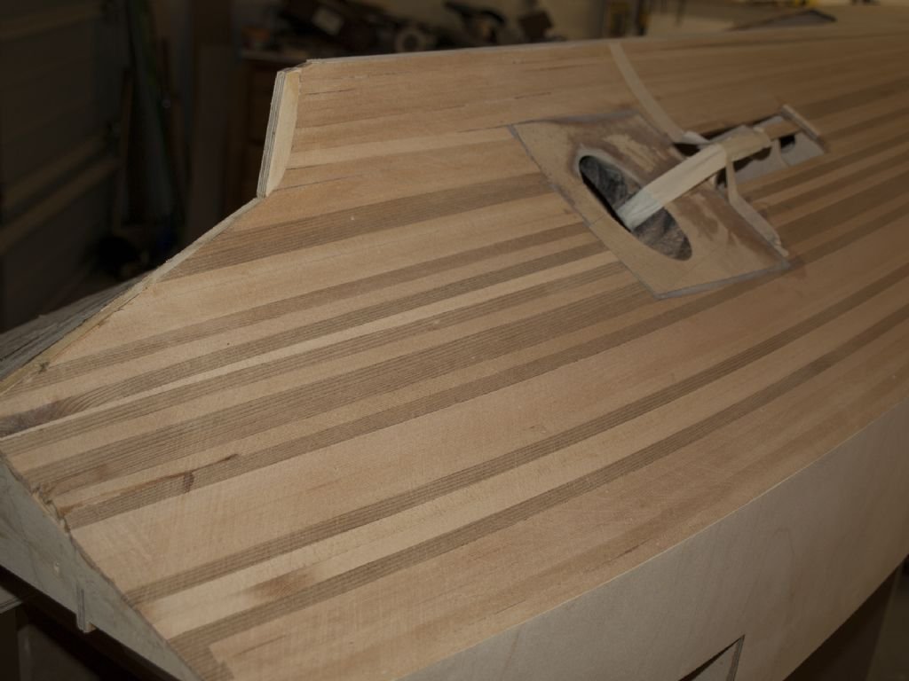
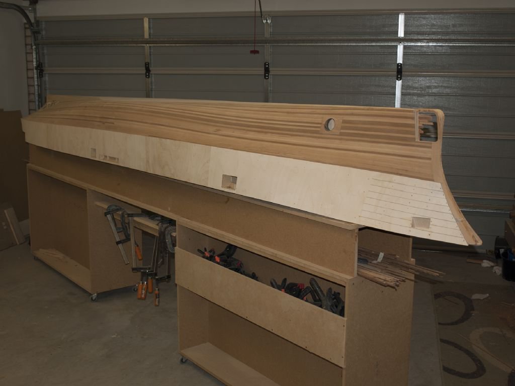
Today started to cut the model components on the CNC but first the bread and Butter lower hull finished ready for shaping.

- 454 replies
-
- 9
-
-
-
- Union Steamship Company
- Stepcraft 840
- (and 3 more)
-
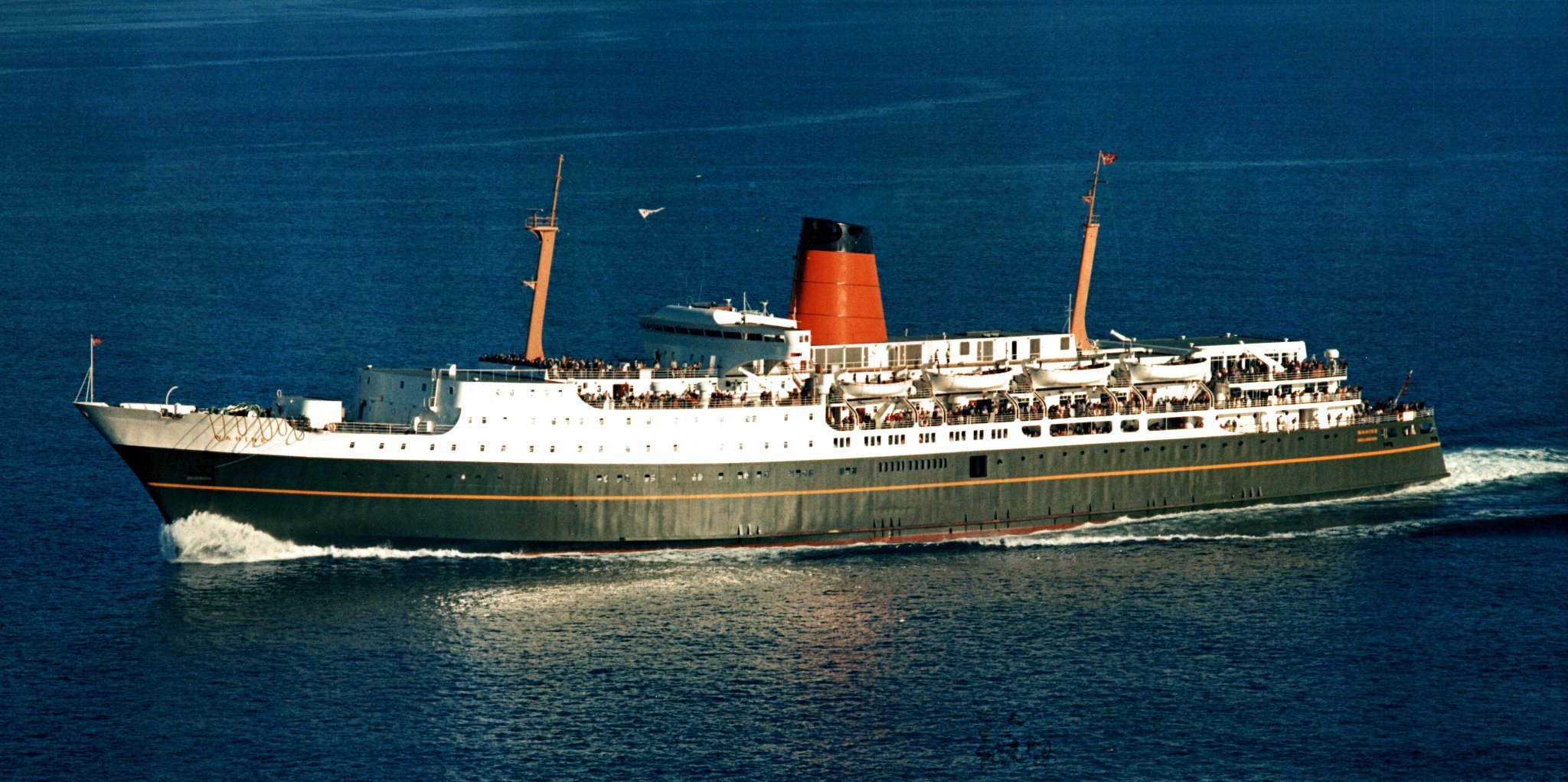
Hi John and Harry Yes it is certainly one of those "where was I when" moments, I was only born in 71 so not even alive although I am from Wellington, but half my family worked for the Union Steamship company and the Naval Architect who designed her was a friend of the family so it all became too much to ignore, I fell in love with the ship because of her looks, not because of her fate although in saying that a good deal of the reference I have is from the wreck including 4 hours of video documenting her scrapping as well as just her short 2 year life. John I never knew that was planned, luckily it blew out as fast as it hit, by 11.00am it was just a regular Wellington Storm but yes it was a very significant moment for design to, many Ro Ro rules and standards were changed because of her sinking and ways of stopping free surface water effect. Harry you are correct, not one person died on the ship, they died sadly on the rocks in the monstrous sea breaking on the shore or a couple of exhaustion after floating around for so long waiting to be rescued. her looks continue to inspire artists and modellers, I frequently get requests for sets of plans and photos for things ranging from paintings to models, even from people with no ties to NZ, quite amazing really.

- 454 replies
-
- 11
-
-
-
- Union Steamship Company
- Stepcraft 840
- (and 3 more)
-
Hello My name is Richard. I have just joined this forum in the hopes to get some help and tips when I need it for my large TEV Wahine build project I am restarting after couple of years and also just to be able to share the knowledge I have on model building after 40 years of building large scale hulls, I have some experience in design of real ships, test tank model production and have done a lot of the 3d design elements of this in Rhino3D professionally. more recently I now do 3d modelling for film and TV but I have never stopped actual miniature modelling either. I now find myself merging the skills I have gained to build models that use accurate 3d design , production of parts using traditional techniques as well as CNC, resin printing and photoetch to create fittings. Not sure how many models in this site are RC but I have been impressed for a while at the standard of the work and a good number of large boats to, which is great to see. A lot of the holes in my knowledge are based around electronics and lighting , although I think once I start fitting out I will be presented with many ideas I had not thought of to. The build I am in the middle of is big and any help I can get will be well received and I will endeavour to provide help also on subject such as 3d drafting of boats from plans or offsets, and accurate ways to build very accurate fair hulls to the standard of test tank models if required, I have considerable experience in the woodwork field as I have said, this includes most of my younger life fitting out super yachts and boat building full size yachts, also guitar building so I am full of tips for high end woodwork and techniques for hull creation. I look forward to doing this build and documenting the process on here.
-
Hi Brian Sort of correct, she was caught in a double Cyclone in Wellington New Zealand and foundered with loss of 51 lives. Here is an archived website about it here. https://ndhadeliver.natlib.govt.nz/webarchive/wayback/20160417074849/http:/www.thewahine.co.nz/Time.html
- 454 replies
-
- 3
-
-
- Union Steamship Company
- Stepcraft 840
- (and 3 more)
-
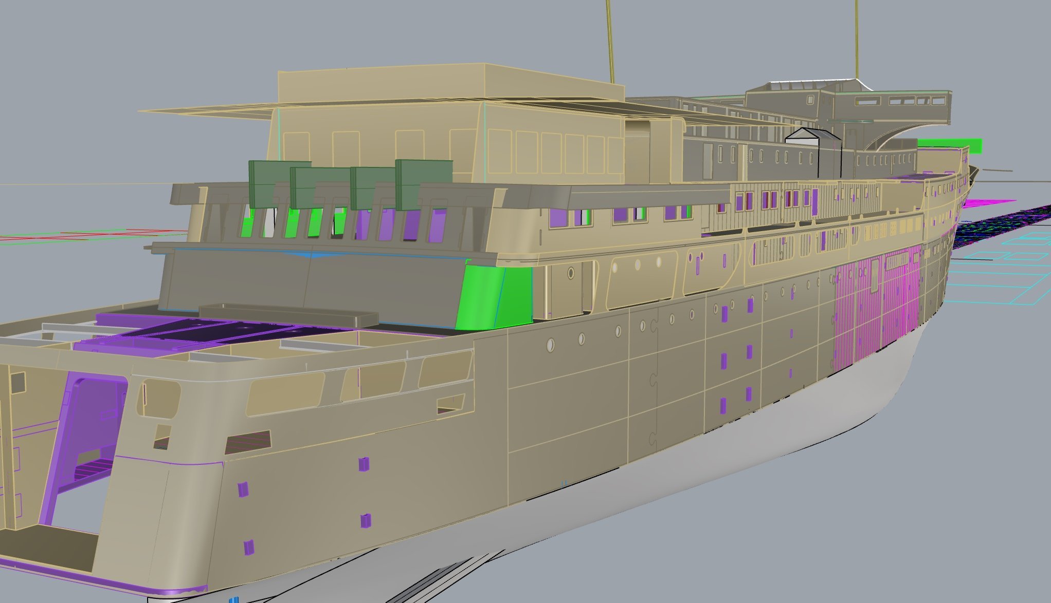
This part of the process has taken many weeks to accomplish, so that the model is built in a way that locates every part accurately into others with tabs or half joints, also to ensure that parts go together so that they don't interfere with access to hull interior, I also had to be very careful not to build in problems where parts could not be assembled as they had to be slid or forced into 2 directions at once so assembly order became VERY important. There are 4 interior spaces that need to be fitted out as well and these had to be designed so they could be done but still have access to hull.
- 454 replies
-
- 2
-
-
- Union Steamship Company
- Stepcraft 840
- (and 3 more)
-
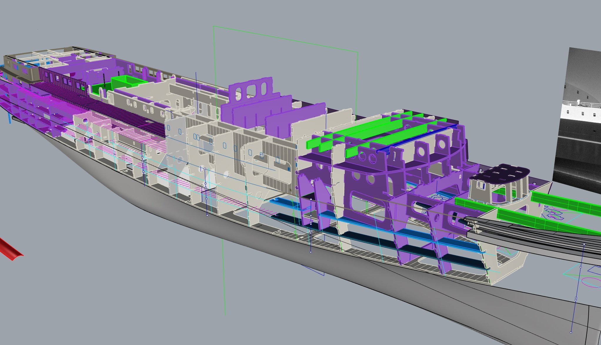
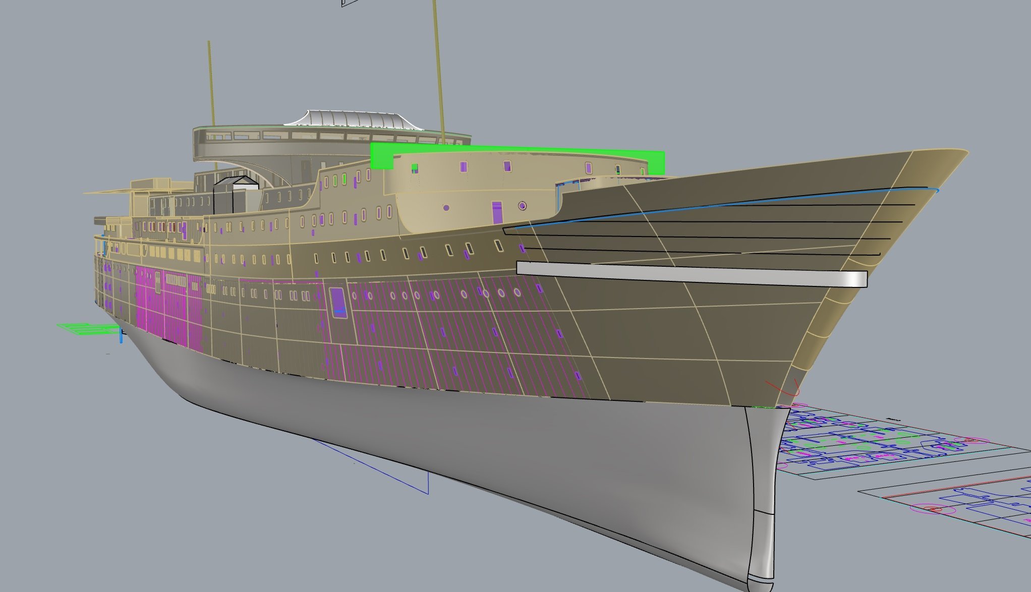
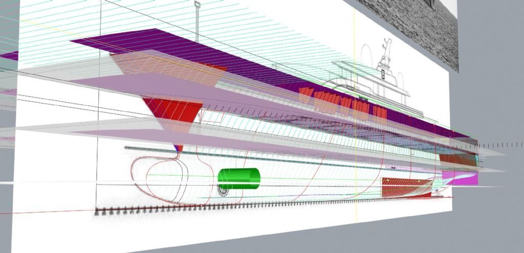
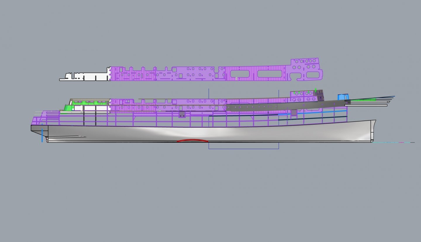
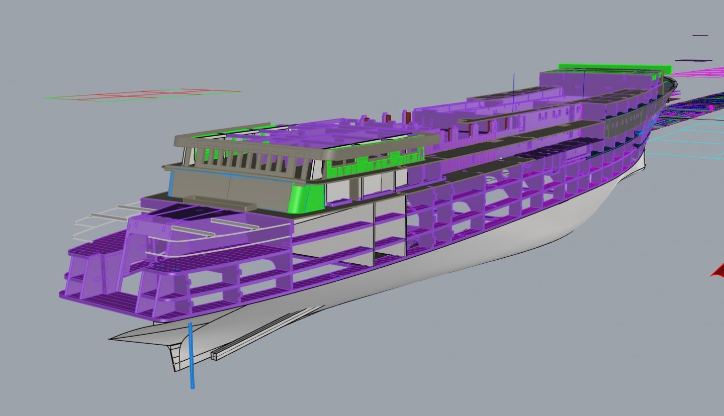
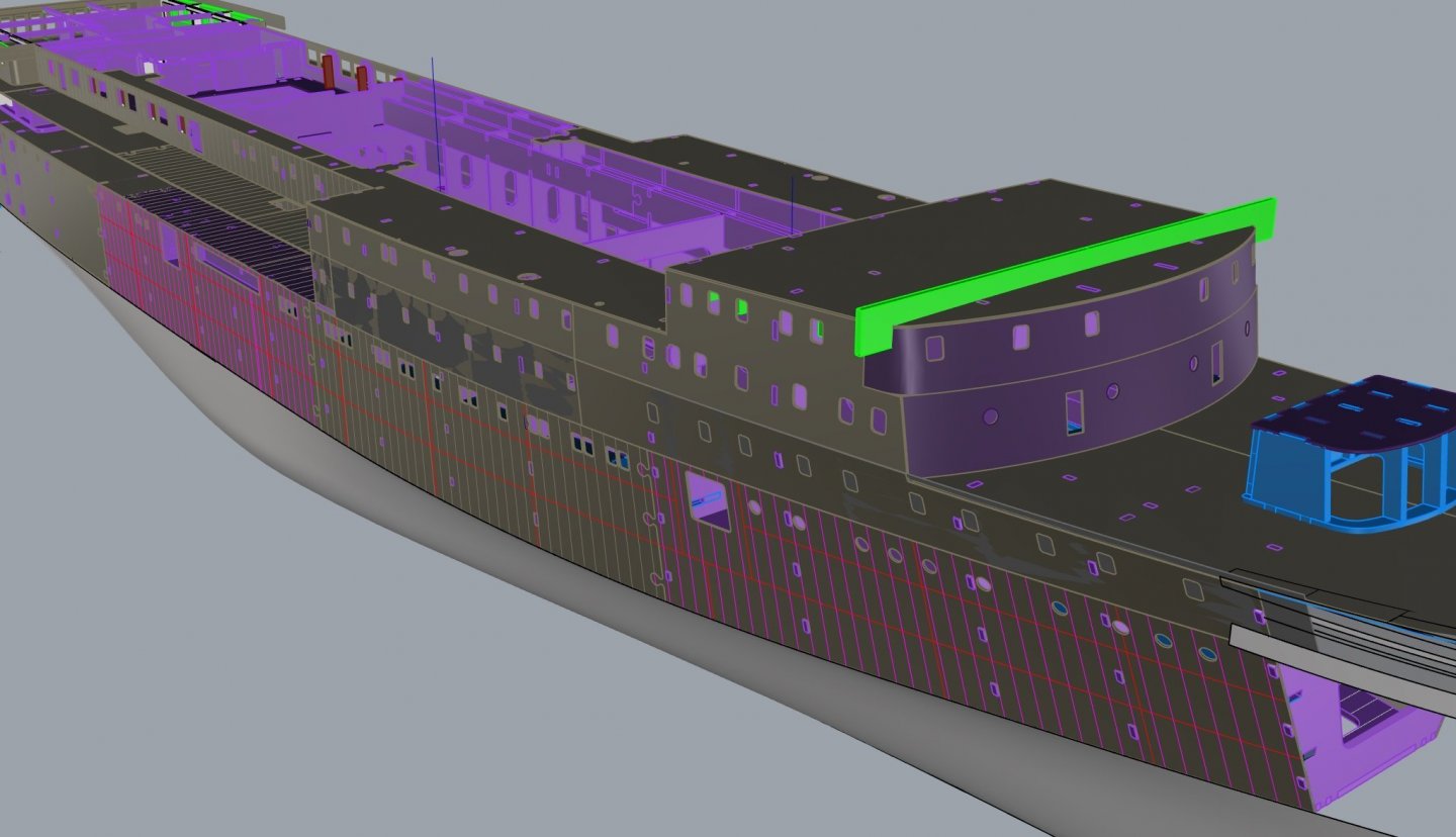
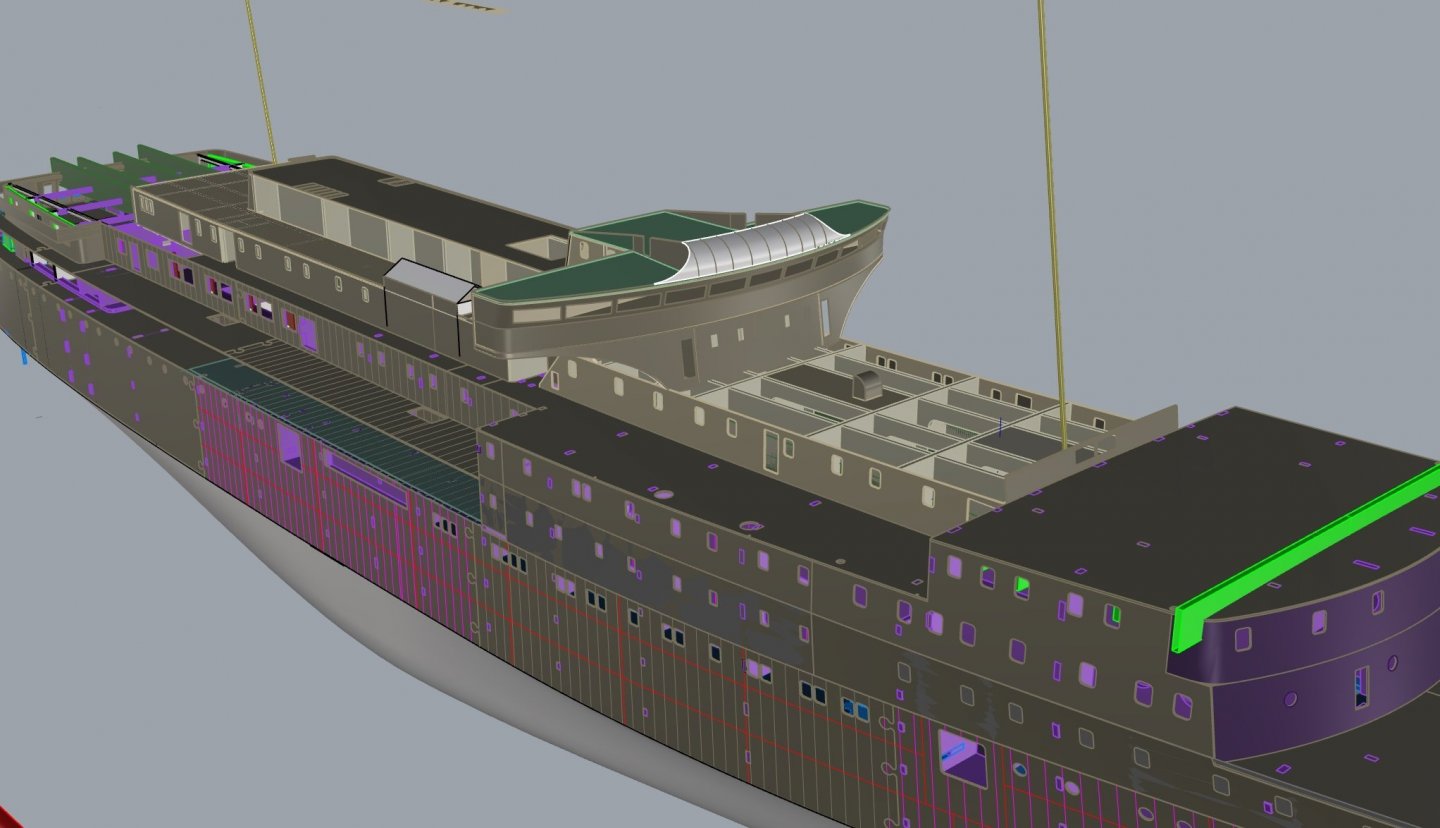
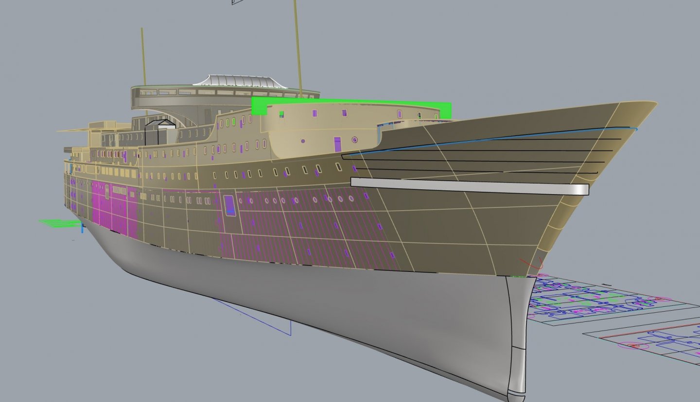
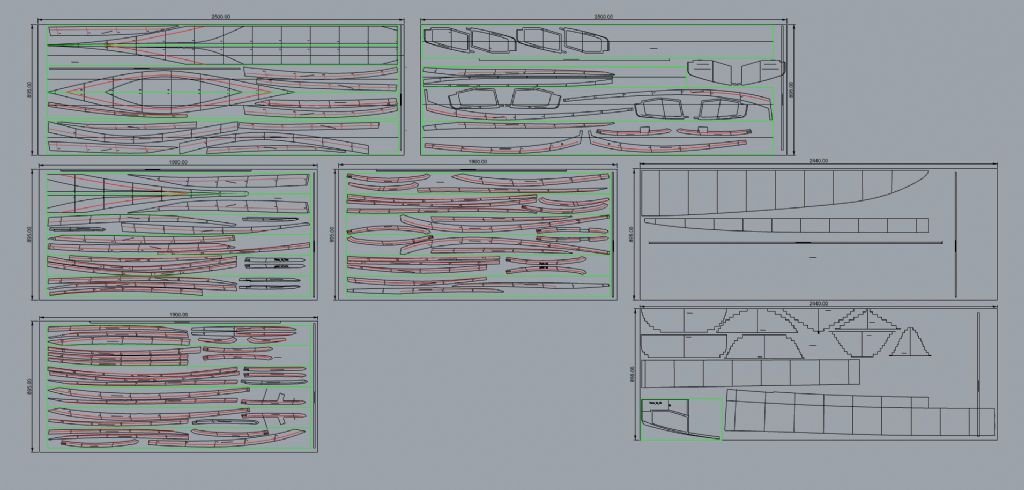
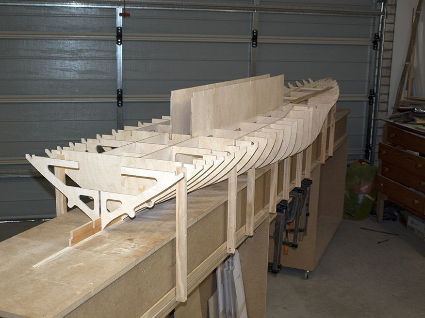
You will notice above the substantial Aluminium beams on the building board. Here are some images of the cad model a few hours away from being ready to cut the parts. Assembly should be fairly quick as it all slots together, yes I have done fit tests and yes it does go together. The first image shows the main longitudinal girders that help tie it all together and the first 3 images are with the superstructure lid off, the 4th shows it on.

- 454 replies
-
- 14
-
-
-
- Union Steamship Company
- Stepcraft 840
- (and 3 more)
-
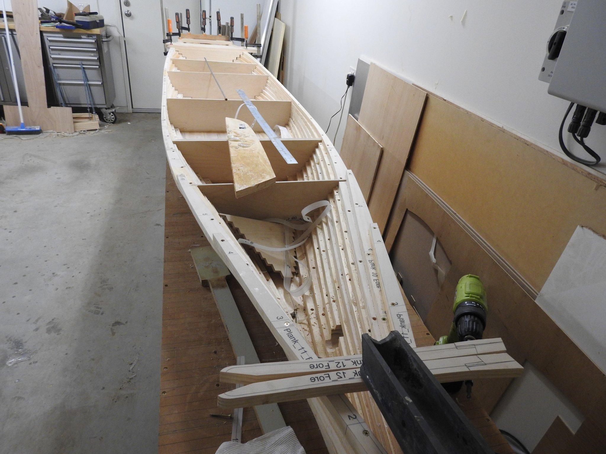
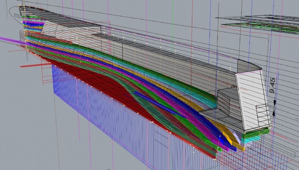
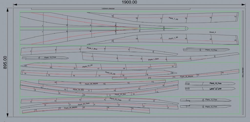
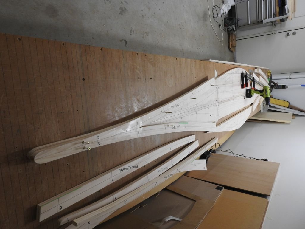
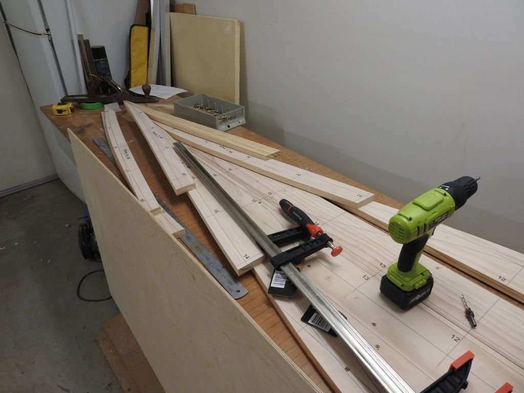
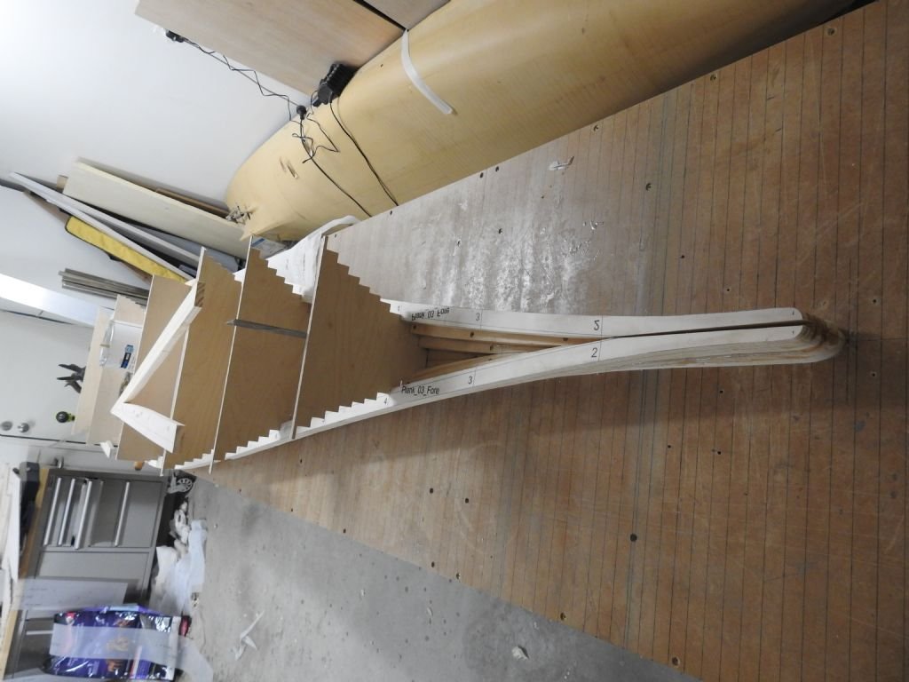
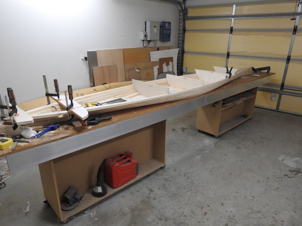
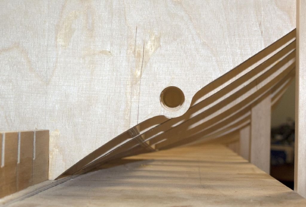
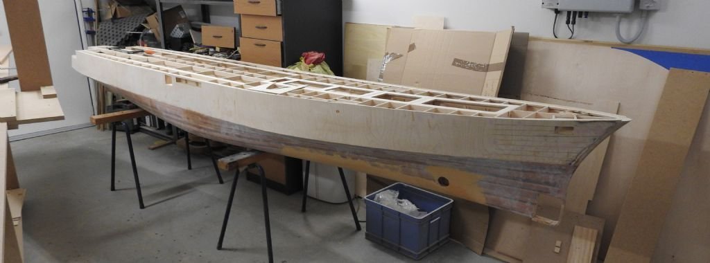
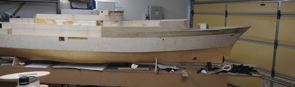
So that was the first go at the hull which I was forced to abandon due to structural issues in the glassing of the hull. Below is the new hull and shots showing how it was planned and broken into shorter sections per layer with stepped bulkhead to keep alignment accurate athwartships. The tug is an empire class tug (Tapuhi) as a service model to the main

- 454 replies
-
- 9
-
-
- Union Steamship Company
- Stepcraft 840
- (and 3 more)
-
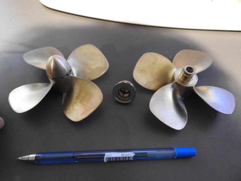
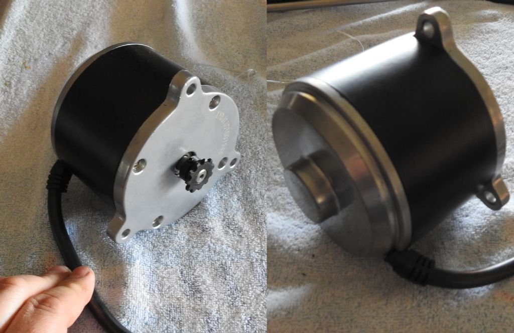
Hi Everybody This is my first time posting on this site although I am not new to model building. Several years ago while I was working nights I started a build of an RC model on a rather large scale of 1/35. Earlier this year I came back to it to finish it and found several major structural problems had developed due to the heat and humidity in my country, I could hve tried to fix what I had done but opted to start again and this time instead of Plank on frame I have gone with bread and butter for lower hull and plywood for the rest. Another reason for the redo is I recently purchased Stepcraft 840 CNC so will be able to translate the design into the model with much much greater accuracy. This model was initially on a build blog on another site but this has stopped being fruitful and after all the whole purpose to build blogs is to give and receive help and tips . I am nearly 50 years old and been modelling ships all my life though not this big, my father before me also built models on commission to shipping companies on 1/8 scale My background is in both furniture building for 16 years nand 20 years of 3d modelling and ship design, my main software being Rhino ,Modo and Maya. Over the recent weeks I have been building the framing and shell structure in 3d and nesting ,the parts on sheets ready to be cut on the CNC. The approach of this structure is 6.5mm 5 ply framework with a 2mm 5 ply covering to box it all out, this has all the openings cut in etc 1.5mm oversize and then the whole is plated properly with .5mm ply which also has all openings and doors etc cut into it as well as curtain plates etc, this models disp in water is 193kg and runs 2 24 volt, 450w motors powering 2 custom made 100mm props from Simon Higgins in the UK, he is also currently building 2 working lateral thrusters as they are beyond my metalwork ability. This ship was one of the most beautiful vessels built on the Clyde in the 60's. I have many links to this ship in my past and have a massive collection of plans of this ship 200 original plans and hundreds of photos. No part of ship is not photographed and plans for all of it are accounted for. I will give a few images of the first attempt so people can see the size and work that went into the model first time and will follow up with the hull as it is now and some shots of the cad model
- 454 replies
-
- 15
-
-
-
- Union Steamship Company
- Stepcraft 840
- (and 3 more)