HOLIDAY DONATION DRIVE - SUPPORT MSW - DO YOUR PART TO KEEP THIS GREAT FORUM GOING! (Only 20 donations so far - C'mon guys!)
×
Richard Dunn
-
Posts
529 -
Joined
-
Last visited
Content Type
Profiles
Forums
Gallery
Events
Everything posted by Richard Dunn
-
 Realtime is really more about the texturing and materials nowdays, polycount is able to be quite high, of course you don't abuse it but yeah the baking from high to low poly is the only real difference. I use Modo and Maya for most of my Polygon modelling but incorporate rhino quite often in that to.
 -
I did consider HMS Victory Kevin but its about as hard as it gets and not for the faint hearted. I also thought about Sovereign of the Seas now the book is out. Its awesome, I bought it a few weeks ago
-
Yeah I know its tempting to want a ship you need or have some interest in but the reason Cutty Sark was pick is it has a number of things you need to watch out for that will set you up in good stead. Guys don't freak out, its not actually that hard if you follow the right order and procedures, I have done this so long its second nature and even when I taught myself it did not take long. The Cutty Sark has the following points that make it a good subject. No actual as built lines exist All Lines are measured from survey(close but not 100%) The plans by NVM are superb and I will use them as they are works of art and inspiring but you will see how to assess errors and correct. The stern is of the overhanging counter type, which is the most tricky to do. You will learn how to take lines from lines plan and also from a scan , not much different. How to fair station lines and then how to fair longitudinally. How to develop true shapes of plates like the bulwarks around the stern How to set out planking on a hull. I will do it in sections so you can take your time
-
If you guys want to get started I can vouch for this training. https://rhino-3d-classes-from-beginner-to-advanced-lev.teachable.com/p/rhino-3d-v6-xbow-ship-modeling-and-rendering-with-vray-level-2
-
Ok here is the thing, would you rather live and have access to recording , or just videos?. Live you get to ask questions Videos you still can I guess but after the fact. Lets see what interest their is, not sure how people realise its the way of the future even for model builders, because as you guys know if you can make it in 3d you can build, CNC, resin print and even do photo etch although that's vector work. I was intending to do a course on her anyway, here was the initial idea on my artstation page. https://www.artstation.com/artwork/qArwVe
-
I have messaged one of the moderators to see what's what. It wont be for a few weeks mate no hurry.
-
OK then , lets see how to go about getting an online event happening and I will do a reconstruction of the ships form from scan data and the NVM plans and take it to the point where we plank the hull.
-
Well why don't I show you how to do Cutty Sark from the real data from ship?
-
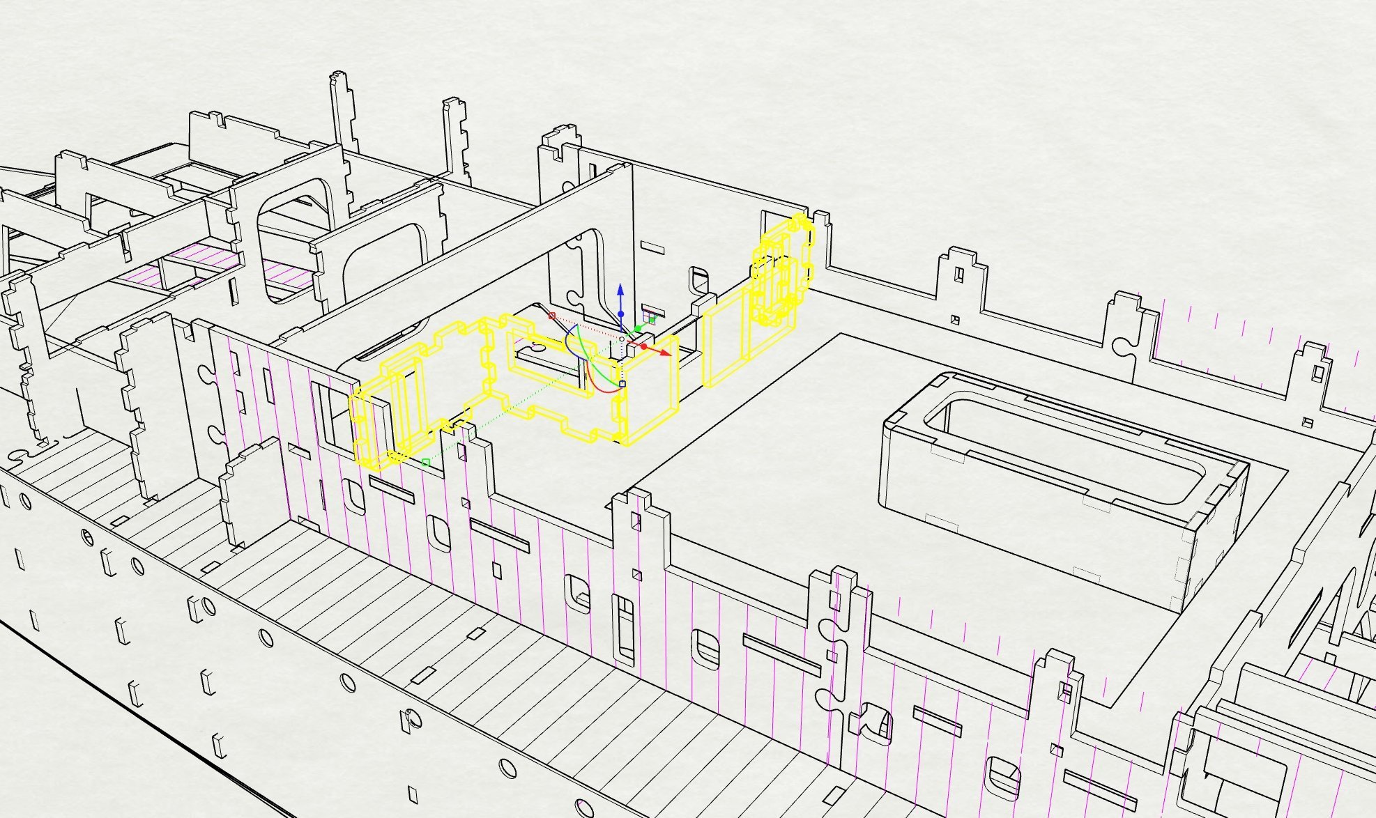
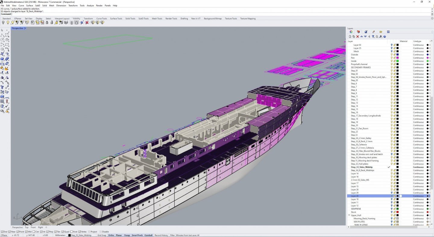
This is a screengrab of my Rhino screen right now and the model I have in my other build blog being cut on cnc, this would take ages in 360 to so , this also has the ability to do true plate development of sheets, unroll developable surfaces so making hull panels etc in true shape is easy, that's another example. Guys give me a hull you can agree on to learn with and I will do the video/videos for you. Lets see what moderators say but I might even do it as a live lesson/course over zoom, that's easier for me and you can ask questions then
-
Rhino does it all, it does Nurbs, Solid, mesh and SubD. Please don't take me wrong I am not on a mission to convert, but I know from my experience as a teacher and my work life Rhino is easier to use and more versatile, I have used 360 to and hated it but I am not here to try to convert, I am just saying if you want to have access to the proper tools needed to do hulls and for that matter the work I am doing on My CNC model you are better off with it, heck I taught Rhino to myself in 4 weeks and then got a job using it! And yes the skills translate across more or less
-
Yeah its funny isn't it because marine and aero are not that dissimilar in terms of surface quality and the needs for fairness etc but you are right. BTW Rhino is $995 US in case anyone is wondering. But you have a deal I will do a video on a hull, deck, superstructure. I might do it for my store as I have training on Artstation already
-
I know I have said this before but if you can stretch the budget and plan on doing this a bit you really are better off with Rhino ,in so many ways I can't sum up here. I know I am a professional 3d artist and yes I have years experience doing boats and ships but I believe anybody can do it with a couple of good tutorials in Rhino and knock out a basic hull in 4-5 hours, Rhino is also a lot less fussy about the input curves and very rarely fails. Not to mention the reason Naval Architects and Boat /Yacht designers use it should say it all. If anyone does try it I will gladly make a tutorial, I am a qualified teacher of 3d modelling and taught it at Uni for 5 years. I know it is not free but really it is a huge investment and you can do soooo much with it. Much easier program to use, more intuitive.
-
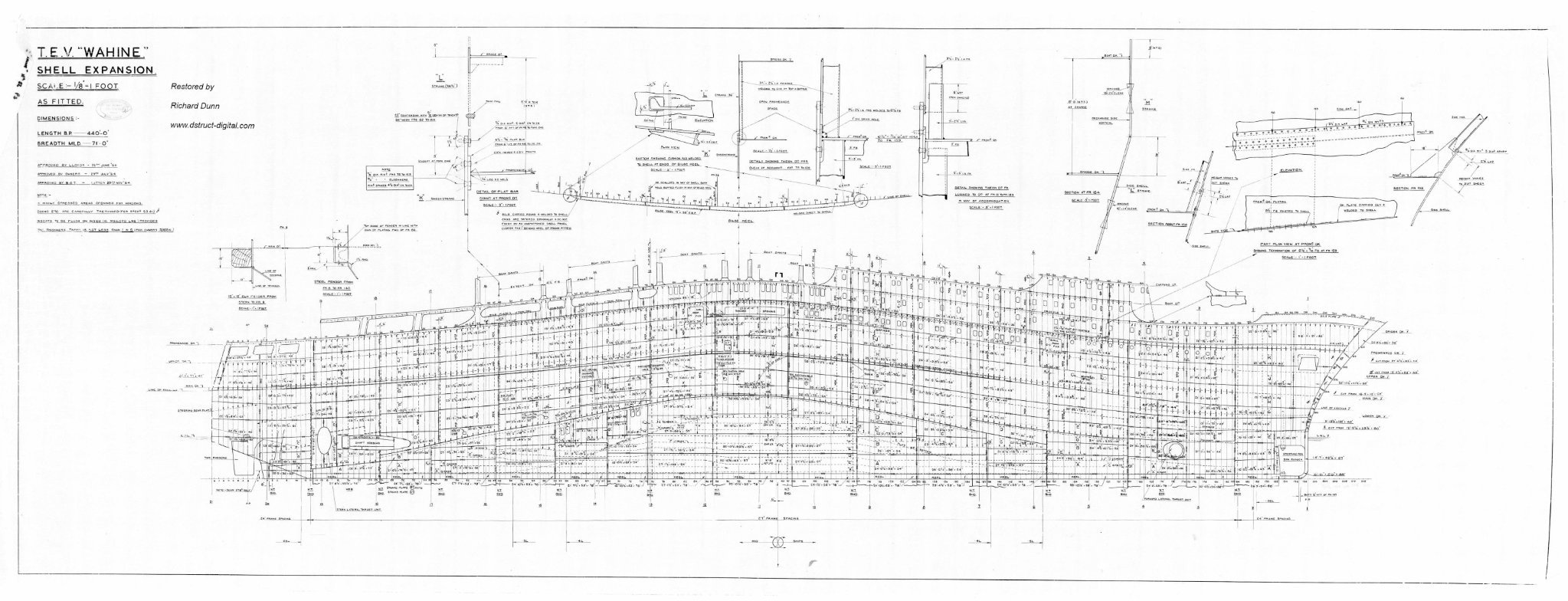
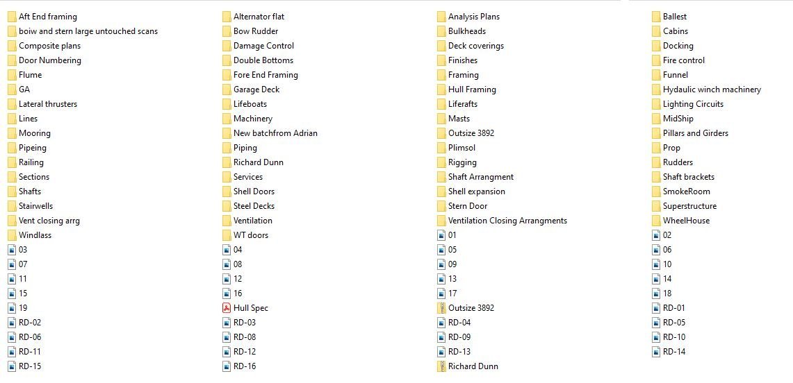
This is the excellent Expansion I have to work with to, it needed very little work other than to straighten up the baseline, this is a low res version, the full size is 200mb in size. As fitted to which is rare, one of 380 plans I have of this ship the folders contain several plans in each

- 454 replies
-
- 7
-

-
- Union Steamship Company
- Stepcraft 840
- (and 3 more)
-
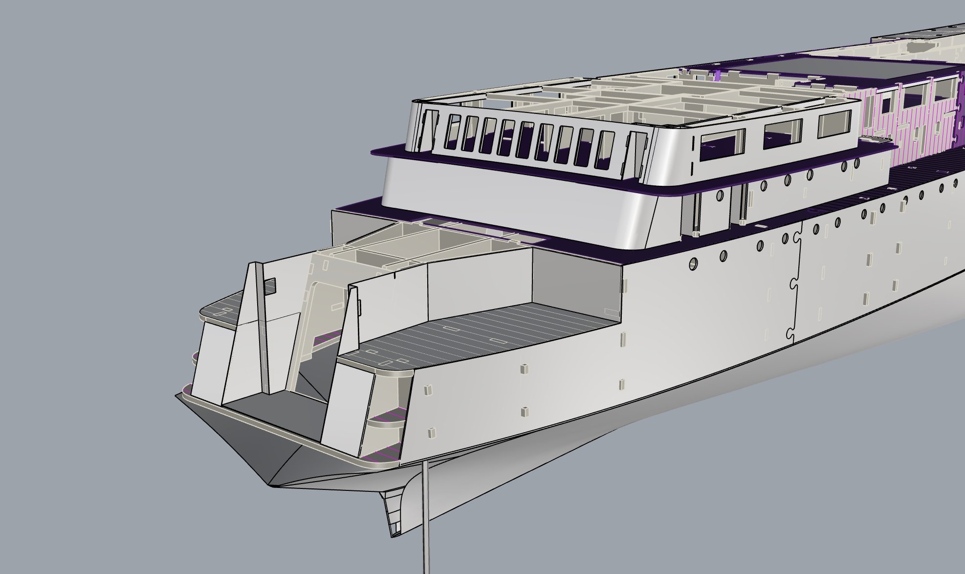
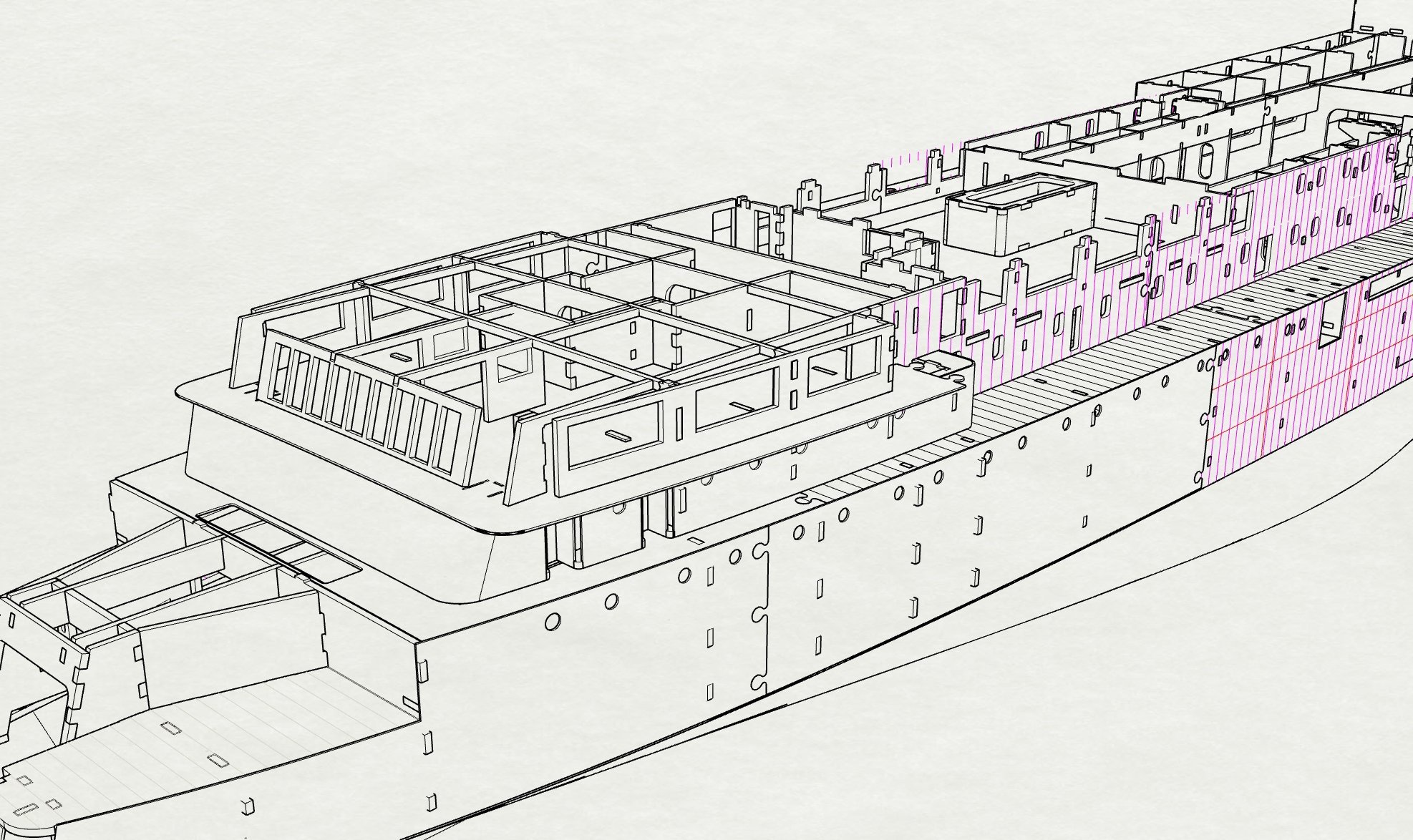
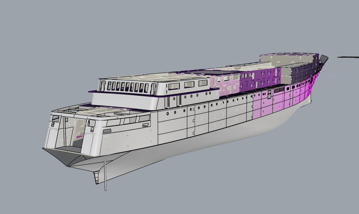
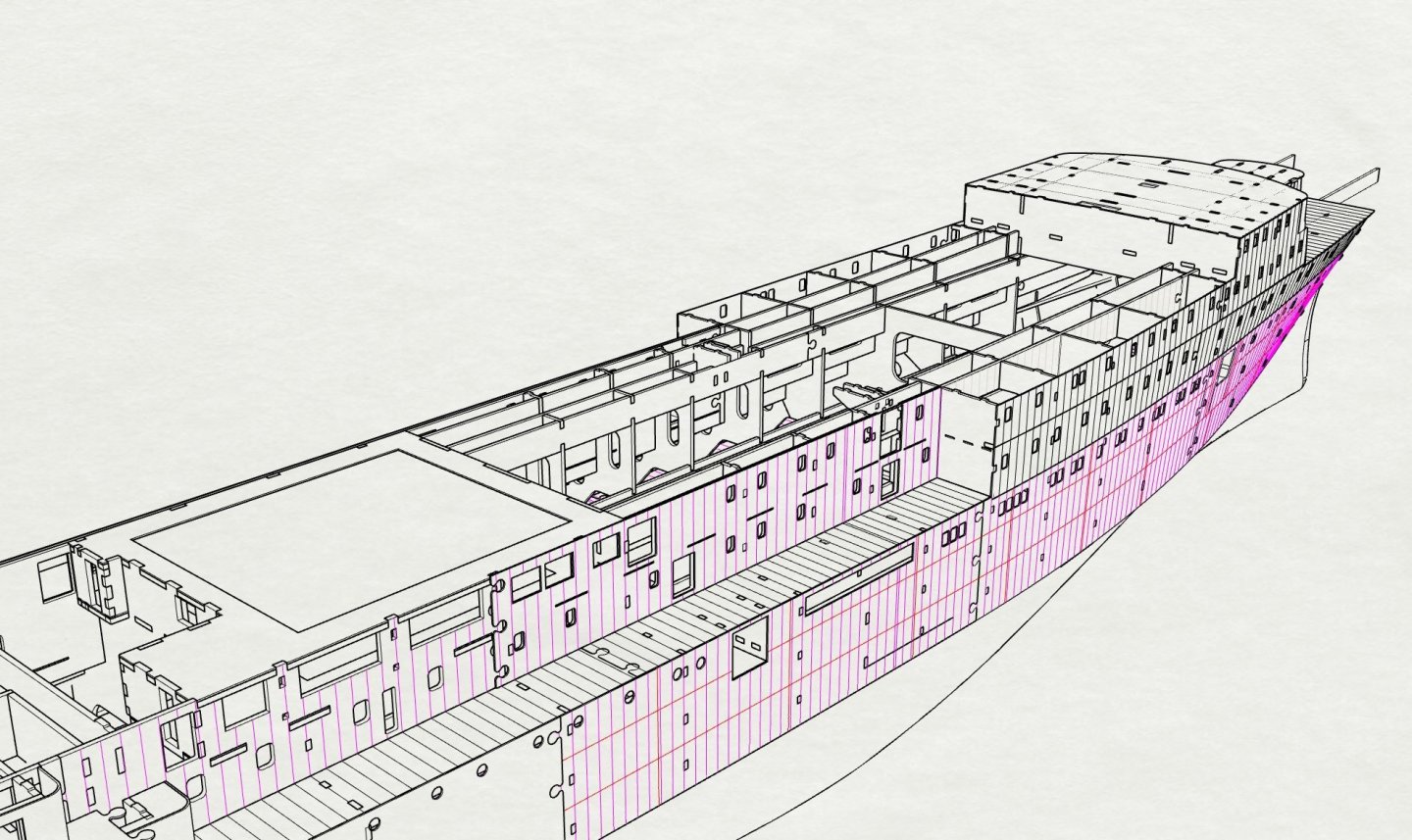
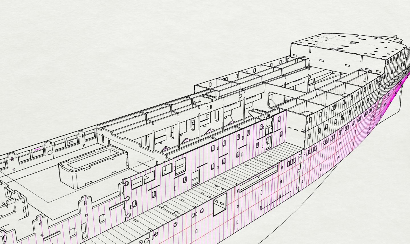
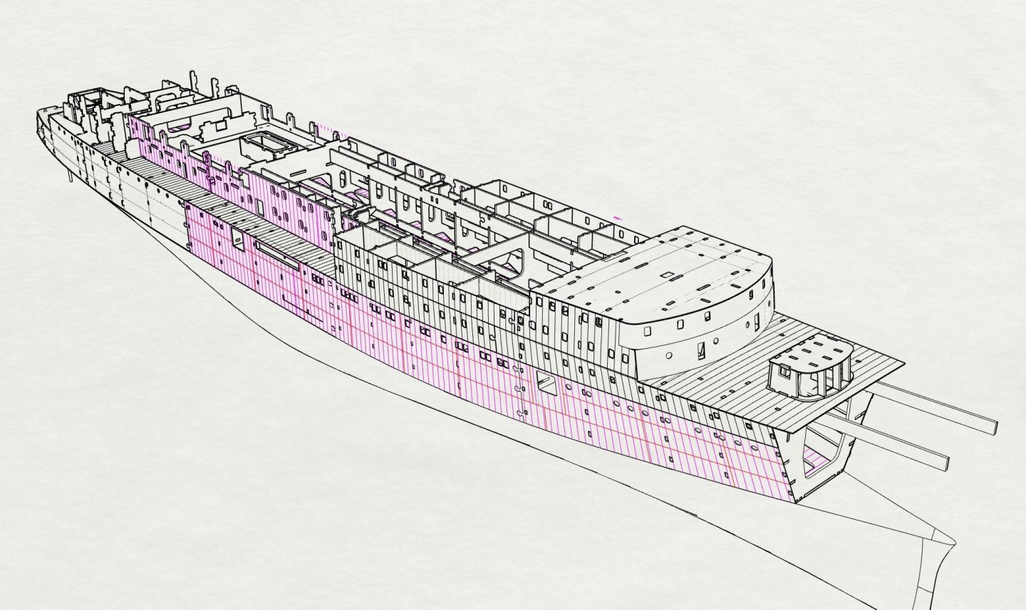
Step 32 Hull plating aft section not yet cut, .4mm
- 454 replies
-
- 7
-
-
- Union Steamship Company
- Stepcraft 840
- (and 3 more)
-
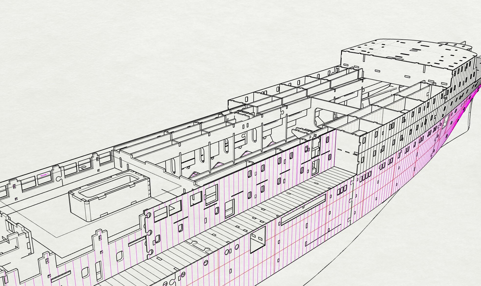
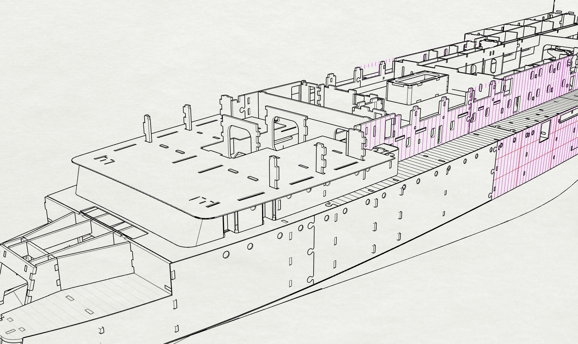
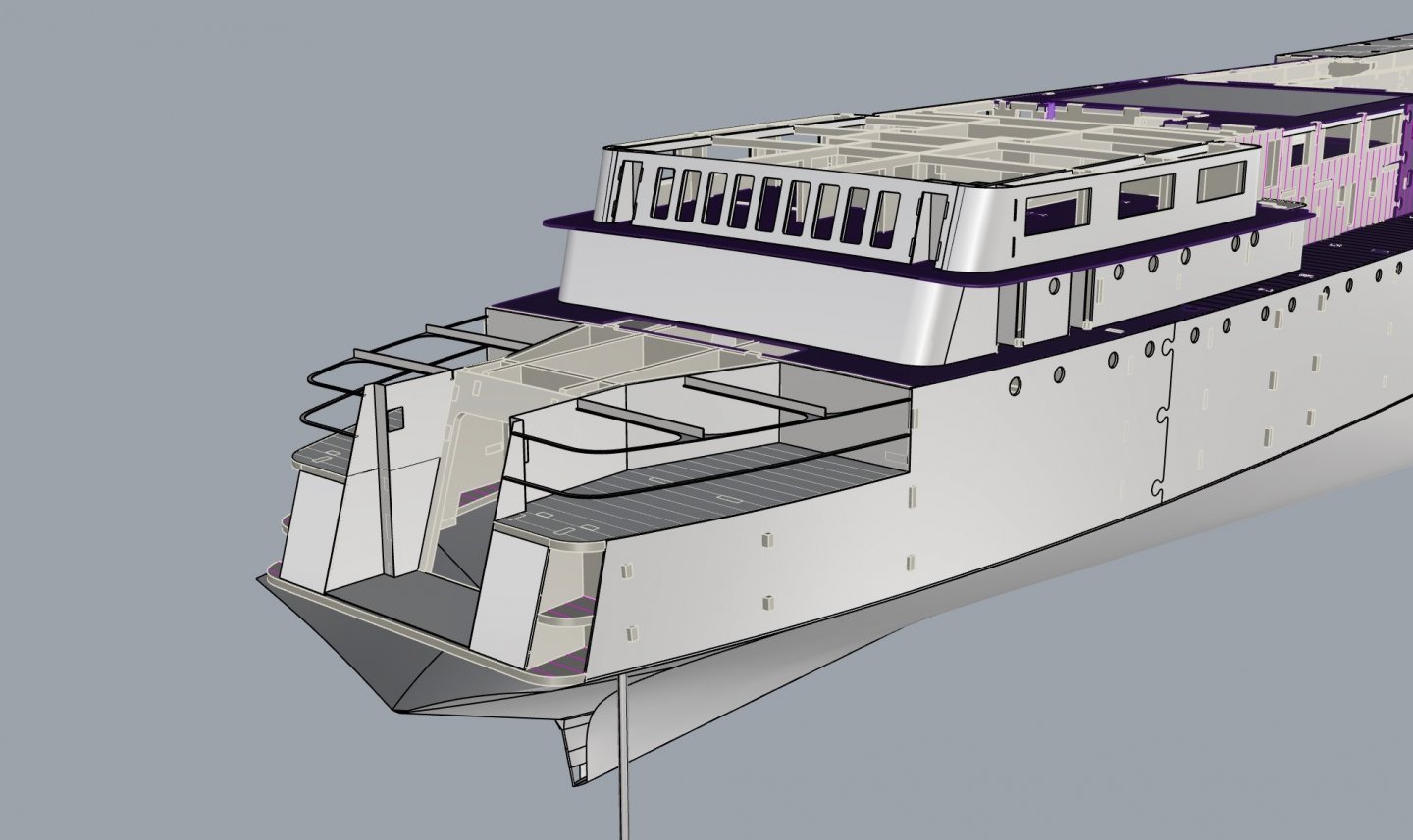
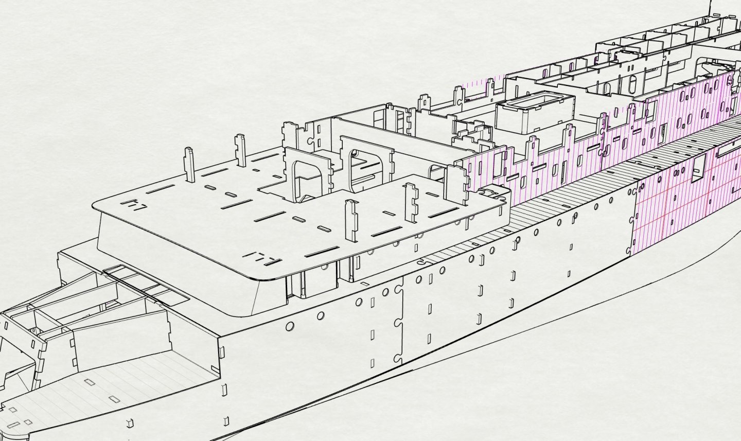
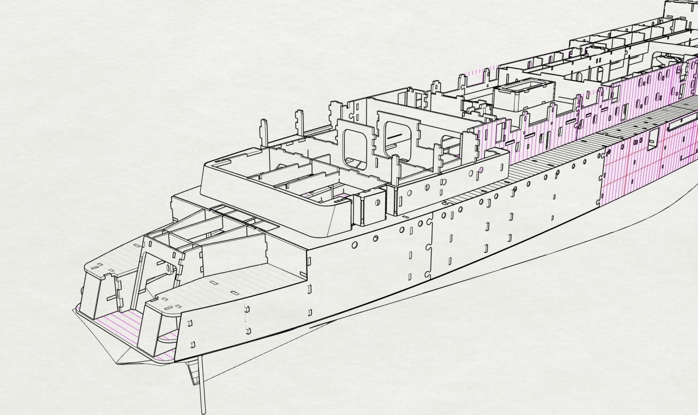
Step 31_Mooring deck frames, (bulwark stays and vertical stiffeners not shown) Mooring deck internals need to be finished and fitted out at this stage.
- 454 replies
-
- 6
-
-
- Union Steamship Company
- Stepcraft 840
- (and 3 more)
-
Step 29 Smokeroom ceiling and hatch (shown closed)
- 454 replies
-
- 3
-
-
- Union Steamship Company
- Stepcraft 840
- (and 3 more)
-
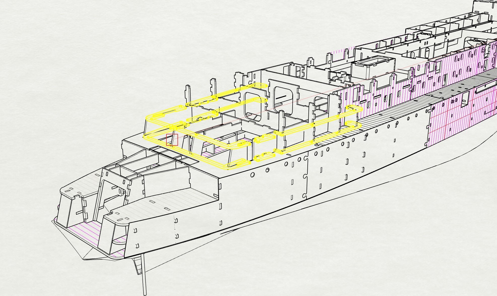
Step 28 filler blocks to form hatch coaming
- 454 replies
-
- 2
-
-
- Union Steamship Company
- Stepcraft 840
- (and 3 more)
-
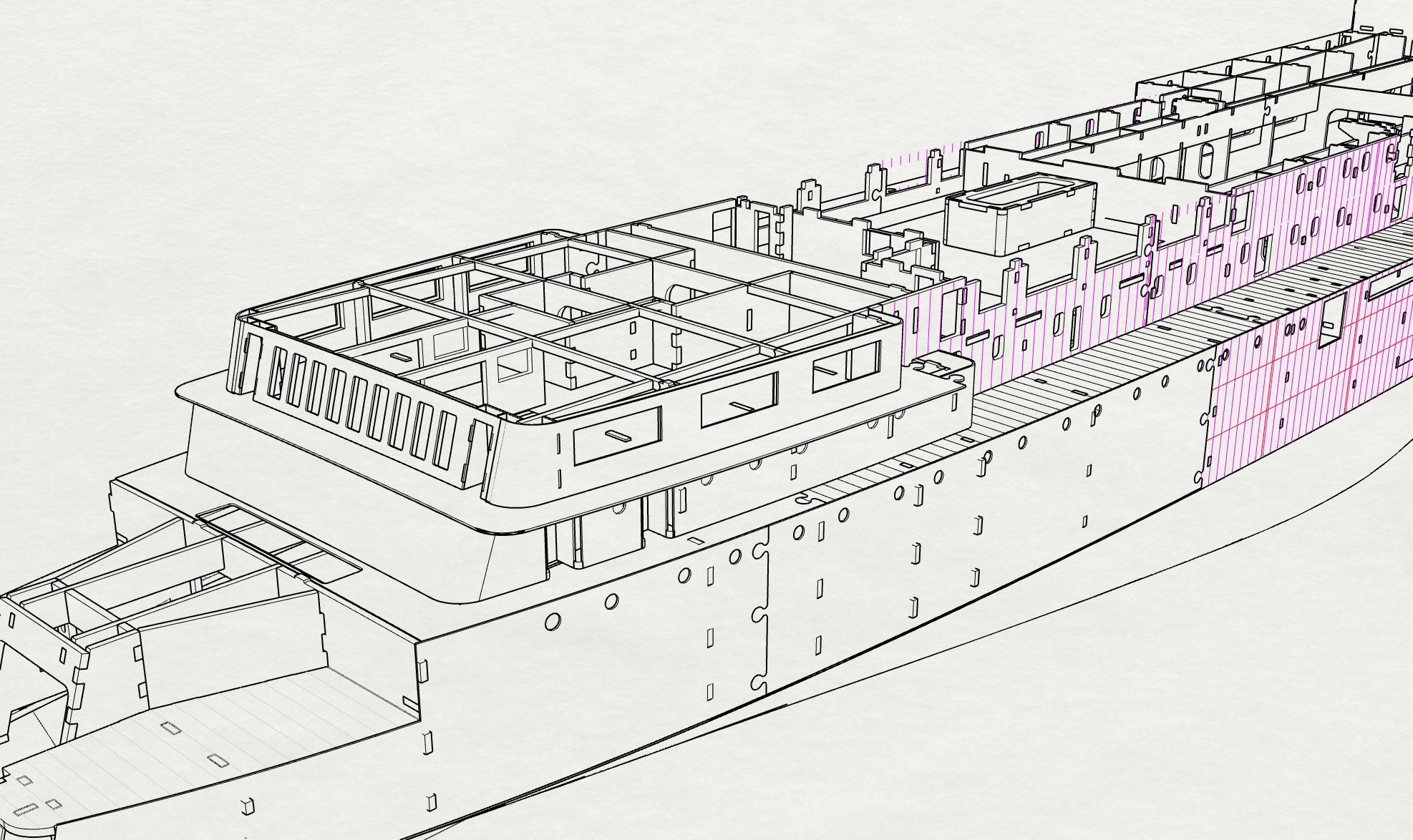
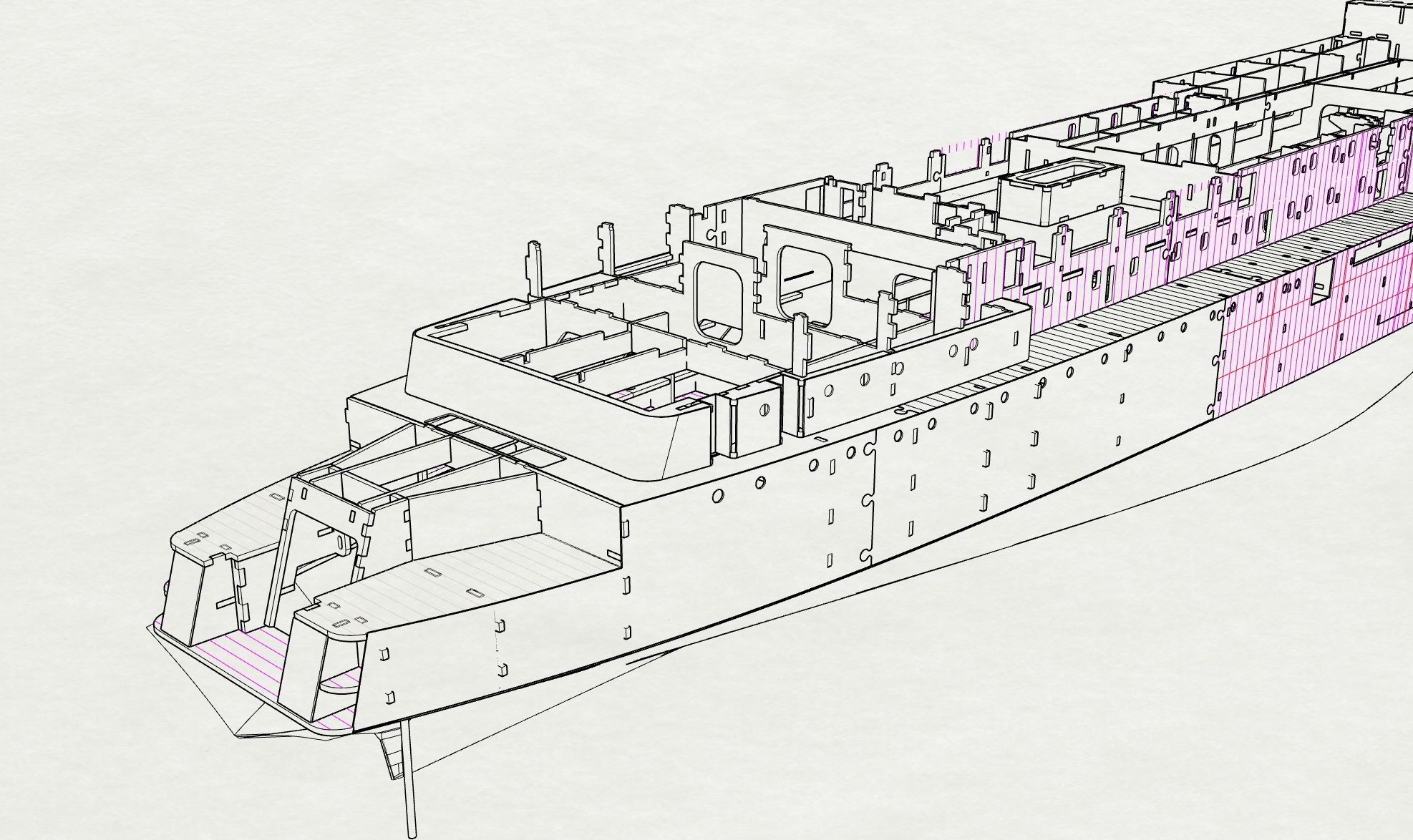
Step 25 B Deck aft _slide down over frame heads(this also forms floor of highly visible Cafetaria aft needs needs to be fitted out
- 454 replies
-
- 1
-
-
- Union Steamship Company
- Stepcraft 840
- (and 3 more)
-
Step 24 Aft Superstructure covering 2.1mm
- 454 replies
-
- 1
-
-
- Union Steamship Company
- Stepcraft 840
- (and 3 more)
-
Step 21 Forward fanroom, unglued as it acts as Thruster hatch for maintenance
- 454 replies
-
- 1
-
-
- Union Steamship Company
- Stepcraft 840
- (and 3 more)